JP2017158024A - Apparatus control device, apparatus control system, and apparatus control method - Google Patents

Apparatus control device, apparatus control system, and apparatus control method Download PDF

Info

Publication number
JP2017158024A
JP2017158024A JP2016039224A JP2016039224A JP2017158024A JP 2017158024 A JP2017158024 A JP 2017158024A JP 2016039224 A JP2016039224 A JP 2016039224A JP 2016039224 A JP2016039224 A JP 2016039224A JP 2017158024 A JP2017158024 A JP 2017158024A
Authority
JP
Japan
Prior art keywords
information
control
controlled
tag
group
Prior art date
Legal status (The legal status is an assumption and is not a legal conclusion. Google has not performed a legal analysis and makes no representation as to the accuracy of the status listed.)
Pending
Application number
JP2016039224A
Other languages
Japanese (ja)
Other versions
JP2017158024A5 (en
Inventor
寛明 ▲高▼橋
寛明 ▲高▼橋
Hiroaki Takahashi
Current Assignee (The listed assignees may be inaccurate. Google has not performed a legal analysis and makes no representation or warranty as to the accuracy of the list.)
Mitsubishi Electric Corp
Original Assignee
Mitsubishi Electric Corp
Priority date (The priority date is an assumption and is not a legal conclusion. Google has not performed a legal analysis and makes no representation as to the accuracy of the date listed.)
Filing date
Publication date
Application filed by Mitsubishi Electric Corp filed Critical Mitsubishi Electric Corp
Priority to JP2016039224A priority Critical patent/JP2017158024A/en
Publication of JP2017158024A publication Critical patent/JP2017158024A/en
Publication of JP2017158024A5 publication Critical patent/JP2017158024A5/ja
Pending legal-status Critical Current

Links

Images

Landscapes

  • Air Conditioning Control Device (AREA)
  • Selective Calling Equipment (AREA)
  • Telephonic Communication Services (AREA)

Abstract

PROBLEM TO BE SOLVED: To provide an apparatus control device convenient for a user.SOLUTION: An apparatus control device 10 comprises: a communication unit 111 for communicating with a plurality of controlled apparatuses 20; a control unit 110 for transmitting a control command to control at least any of the plurality of controlled apparatuses 20; and a storage unit 113. The storage unit 113 stores the control command and control rule information to determine whether or not to transmit the control command. The control unit 110 selects at least one controlled apparatus 20 to be a transmission destination of the control command from the plurality of controlled apparatuses 20 on the basis of the control rule information, and transmits the control command to the selected controlled apparatus 20.SELECTED DRAWING: Figure 2

Description

本発明は、機器制御装置及び機器制御システムに関し、特に、1つ以上の被制御機器の制御を行う機器制御装置及び機器制御システムに関する。   The present invention relates to a device control device and a device control system, and more particularly, to a device control device and a device control system that control one or more controlled devices.

複数の機器が連動するように制御する制御システムが用いられている。例えば、特許文献1に記載された空気調和システムは、予め決められた基準機器としての空気調和機の動作と連動するように、予め決められた制御対象(制御対象機器)としての汎用機器に対する連動制御を行う。特許文献2に記載された家電制御システムは、同一の部屋に設置された空気調和機及び照明装置を制御する。   A control system that controls a plurality of devices to be linked is used. For example, the air conditioning system described in Patent Document 1 is linked to a general-purpose device as a predetermined control target (control target device) so as to be linked with the operation of an air conditioner as a predetermined reference device. Take control. The home appliance control system described in Patent Literature 2 controls an air conditioner and a lighting device installed in the same room.

特開2008−249233号公報JP 2008-249233 A 特開2014−216835号公報JP 2014-216835 A

しかしながら、特許文献1に記載された空気調和システムでは、基準機器及び連動制御の制御対象機器が固定されているので、システムの運用中において基準機器及び連動制御の制御対象機器を他の機器に任意に変更することができない。特許文献2に記載された家電制御システムでは、基準機器(例えば、空気調和機)及び連動制御の制御対象機器(例えば、照明装置)が互いに同一の室内に設置されている必要がある。したがって、これらのシステムは、ユーザの利便性が低いという問題がある。   However, in the air conditioning system described in Patent Document 1, since the reference device and the control target device of the interlock control are fixed, the reference device and the control target device of the interlock control are arbitrarily assigned to other devices during the operation of the system. Can not be changed. In the home appliance control system described in Patent Document 2, it is necessary that a reference device (for example, an air conditioner) and a control target device (for example, a lighting device) for interlocking control are installed in the same room. Therefore, these systems have a problem that user convenience is low.

そこで、本発明の目的は、上述の課題を解決するためになされたものであり、ユーザの利便性の高い機器制御装置、この機器制御装置を有する機器制御システム、及び機器制御方法を提供することである。   Accordingly, an object of the present invention is made to solve the above-described problems, and provides a device control device that is highly convenient for the user, a device control system having the device control device, and a device control method. It is.

本発明の機器制御装置は、複数の被制御機器を遠隔制御する機器制御装置であって、前記複数の被制御機器と通信する通信部と、前記通信部を介して、前記複数の被制御機器のうちの少なくともいずれかを制御する制御命令を送信する制御部と、情報が格納される記憶部とを備え、前記記憶部は、前記制御命令と、前記制御命令の送信の可否を決定する制御ルール情報とを格納し、前記制御部は、前記制御命令の送信先の少なくとも1つの被制御機器を、前記制御ルール情報に基づいて前記複数の被制御機器の中から選択し、前記選択された被制御機器に前記制御命令を送信することを特徴とする。
本発明の機器制御システムは、複数の被制御機器と、前記複数の被制御機器を遠隔制御する機器制御装置とを備え、前記機器制御装置は、前記複数の被制御機器と通信する通信部と、前記通信部を介して、前記複数の被制御機器のうちの少なくともいずれかを制御する制御命令を送信する制御部と、情報が格納される記憶部とを有し、前記記憶部は、前記制御命令と、前記制御命令の送信の可否を決定する制御ルール情報とを格納し、前記制御部は、前記制御命令の送信先の少なくとも1つの被制御機器を、前記制御ルール情報に基づいて前記複数の被制御機器の中から選択し、前記選択された被制御機器に前記制御命令を送信することを特徴とする。
本発明の機器制御方法は、複数の被制御機器と、前記複数の被制御機器のうちの少なくともいずれかを制御する制御命令及び前記制御命令の送信の可否を決定する制御ルール情報が格納された機器制御装置とを備えるシステムにおける機器制御方法であって、前記制御命令の送信先の少なくとも1つの被制御機器を、前記制御ルール情報に基づいて前記複数の被制御機器の中から選択するステップと、前記選択された被制御機器に前記制御命令を送信するステップとを備えることを特徴とする。
The device control device of the present invention is a device control device that remotely controls a plurality of controlled devices, and a communication unit that communicates with the plurality of controlled devices, and the plurality of controlled devices via the communication unit. A control unit for transmitting a control command for controlling at least one of the control unit and a storage unit for storing information, wherein the storage unit is configured to determine whether or not the control command and the control command can be transmitted. And the control unit selects at least one controlled device as a transmission destination of the control command from the plurality of controlled devices based on the control rule information, and the selected The control command is transmitted to a controlled device.
The device control system of the present invention includes a plurality of controlled devices and a device control device that remotely controls the plurality of controlled devices, and the device control device includes a communication unit that communicates with the plurality of controlled devices; A control unit that transmits a control command for controlling at least one of the plurality of controlled devices via the communication unit, and a storage unit that stores information. A control command and control rule information for determining whether or not to transmit the control command are stored, and the control unit selects at least one controlled device to which the control command is transmitted based on the control rule information. A selection is made from among a plurality of controlled devices, and the control command is transmitted to the selected controlled devices.
The device control method of the present invention stores a plurality of controlled devices, a control command for controlling at least one of the plurality of controlled devices, and control rule information for determining whether or not the control command can be transmitted. A device control method in a system comprising a device control device, comprising: selecting at least one controlled device as a transmission destination of the control command from the plurality of controlled devices based on the control rule information; And the step of transmitting the control command to the selected controlled device.

本発明によれば、ユーザの利便性の高い機器制御装置、この機器制御装置を有する機器制御システム、及び機器制御方法を提供することができる。   ADVANTAGE OF THE INVENTION According to this invention, the apparatus control apparatus with a high user's convenience, the apparatus control system which has this apparatus control apparatus, and an apparatus control method can be provided.

本発明の実施の形態に係る機器制御装置を含む機器制御システムの構成を概略的に示すブロック図である。It is a block diagram which shows roughly the structure of the equipment control system containing the equipment control apparatus which concerns on embodiment of this invention. 機器制御装置の構成を概略的に示すブロック図である。It is a block diagram which shows the structure of an apparatus control apparatus roughly. 複数の被制御機器の各々に関する情報が格納された機器情報テーブル(テーブル1)を示す図である。It is a figure which shows the apparatus information table (table 1) in which the information regarding each of several controlled apparatus was stored. 複数のグループに関する情報が格納されたグループ情報テーブル(テーブル2)を示す図である。It is a figure which shows the group information table (table 2) in which the information regarding a some group was stored. 機器制御命令と、機器制御命令の送信可否を判断するための複数の判断条件との組み合わせが格納された連動制御ルールテーブル(テーブル3)を示す図である。It is a figure which shows the interlocking control rule table (Table 3) in which the combination of a device control command and a plurality of determination conditions for determining whether a device control command can be transmitted is stored. 被制御機器に付与される付与状態タグと、付与状態タグを付与するための複数の判断条件との組み合わせが格納された状態タグ情報更新ルールテーブル(テーブル4)を示す図である。It is a figure which shows the status tag information update rule table (Table 4) in which the combination of the grant status tag given to a controlled apparatus and the some judgment condition for granting a grant status tag was stored. 連動制御処理を示すフローチャートである。It is a flowchart which shows an interlocking control process. 図7に示される状態タグ付与判断処理を示すフローチャートである。It is a flowchart which shows the state tag provision determination process shown by FIG. 図7に示される機器制御処理を示すフローチャートである。It is a flowchart which shows the apparatus control process shown by FIG. 変形例に係る機器制御装置における制御部の構成を示すブロック図である。It is a block diagram which shows the structure of the control part in the apparatus control apparatus which concerns on a modification.

実施の形態.
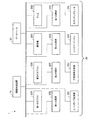
図1は、本発明の実施の形態に係る機器制御システム1の構成を概略的に示すブロック図である。
機器制御システム1は、複数の被制御機器20と、複数の被制御機器20を遠隔制御する機器制御装置10と、データベース30とを有する。
Embodiment.
FIG. 1 is a block diagram schematically showing the configuration of a device control system 1 according to an embodiment of the present invention.
The device control system 1 includes a plurality of controlled devices 20, a device control apparatus 10 that remotely controls the plurality of controlled devices 20, and a database 30.

本実施の形態において、複数の被制御機器20の各々は、例えば、第1のエアコン20A、第2のエアコン20B、掃除機20C、テレビ20D、第1の照明20E、第2の照明20F、第3の照明20G、第4の照明20H、ヒートポンプ給湯器20I、浴室換気乾燥機20J、レンジフードファン20K、及びIH(Induction Heating)クッキングヒーター20Lのうちの少なくともいずれかである。ただし、被制御機器20は、これらに限定されるものではない。例えば、被制御機器20は、機器制御装置10から遠隔操作を受け付けることのできる機器であればよい。複数の被制御機器20の各々は、同一の部屋に設置されていてもよく、少なくとも2つの被制御機器20が互いに異なる部屋に設置されていてもよい。   In the present embodiment, each of the plurality of controlled devices 20 includes, for example, a first air conditioner 20A, a second air conditioner 20B, a cleaner 20C, a television 20D, a first illumination 20E, a second illumination 20F, The third illumination 20G, the fourth illumination 20H, the heat pump water heater 20I, the bathroom ventilation dryer 20J, the range hood fan 20K, and the IH (Induction Heating) cooking heater 20L. However, the controlled device 20 is not limited to these. For example, the controlled device 20 may be any device that can accept a remote operation from the device control apparatus 10. Each of the plurality of controlled devices 20 may be installed in the same room, or at least two controlled devices 20 may be installed in different rooms.

以下の説明において、特に明示する場合を除き、複数の被制御機器20の各々を、“被制御機器20”と表現する。   In the following description, unless otherwise specified, each of the plurality of controlled devices 20 is expressed as “controlled device 20”.

機器制御装置10、被制御機器20、及びデータベース30は、相互に通信が可能である。通信を行う手段として、例えば、Ethernet(登録商標)、無線LAN(Local Area Network)又は赤外線通信等が挙げられるが、これらに限定されるものではない。通信を行う手段は、後述する機器制御命令(制御命令)を送信することのできる通信媒体であればよい。   The device control apparatus 10, the controlled device 20, and the database 30 can communicate with each other. Examples of the means for performing communication include, but are not limited to, Ethernet (registered trademark), wireless LAN (Local Area Network), or infrared communication. The communication means may be any communication medium that can transmit a device control command (control command) to be described later.

機器制御装置10は、被制御機器20に機器制御命令(制御命令)を送信することができる。機器制御命令は、例えば、電源のオンオフの切り替え、運転モードの設定若しくは切り替え、又は被制御機器20の設定情報の変更などの制御命令である。例えば、第1のエアコン20Aには、「電源:入」、「電源:切」、「運転モード:冷房」、「運転モード:暖房」、「設定温度:28℃」、及び「設定温度:29℃」等の複数の制御内容が備えられている。これらの制御内容の各々について、互いに異なる機器制御命令が割り当てられる。   The device control apparatus 10 can transmit a device control command (control command) to the controlled device 20. The device control command is, for example, a control command such as power on / off switching, operation mode setting or switching, or setting information change of the controlled device 20. For example, the first air conditioner 20A includes “power: on”, “power: off”, “operation mode: cooling”, “operation mode: heating”, “set temperature: 28 ° C.”, and “set temperature: 29”. A plurality of control contents such as “° C.” are provided. Different device control commands are assigned to each of these control contents.

機器制御命令は、例えば、各制御内容が、互いに識別できるように符号化された値である。制御内容と符号化された値(機器制御命令)とは、被制御機器20の種類(機器種別)ごとに予め関連付けられている。   The device control command is, for example, a value encoded so that the control contents can be distinguished from each other. The control content and the encoded value (device control command) are associated in advance for each type (device type) of the controlled device 20.

制御内容と符号化された値との対応関係は、例えば、ECHONET Lite(登録商標)のような、標準化された規格に準拠してもよい。制御内容と符号化された値との対応関係は、特定の機器制御システムを構成する機器制御装置10と被制御機器20との間でのみ共通化されたものであってもよい。   The correspondence between the control content and the encoded value may be based on a standardized standard such as ECHONET Lite (registered trademark). The correspondence relationship between the control content and the encoded value may be shared only between the device control apparatus 10 and the controlled device 20 constituting a specific device control system.

機器制御装置10が機器制御命令を送信するタイミングの決定、機器制御命令を送信する送信先(複数の被制御機器20のうちの少なくとも1つの被制御機器20)の選択、及び制御内容の選択は、機器制御装置10が自動的に行ってもよく、機器制御システム1の機器制御装置10のユーザによる明示的な指示に従って機器制御装置10が行ってもよい。   Determination of timing at which the device control apparatus 10 transmits a device control command, selection of a transmission destination (at least one controlled device 20 of the plurality of controlled devices 20) to which the device control command is transmitted, and selection of control contents The device control apparatus 10 may perform automatically, or the device control apparatus 10 may perform according to an explicit instruction from the user of the device control apparatus 10 of the device control system 1.

ユーザが明示的な指示を行う場合は、ユーザは、機器制御装置10を遠隔操作するリモコン(リモートコントローラ)を操作すればよい。また、機器制御装置10は、ユーザが操作を行うためのボタンを備えており、ユーザが押下したボタンに対応した機器制御命令を送信してもよい。さらに、機器制御装置10は、操作表示部117を備え、ユーザが操作を行い、機器制御命令を送信する対象(複数の被制御機器20のうちのいずれか)の選択、及び制御内容の選択を行うことができる。   When the user gives an explicit instruction, the user may operate a remote controller (remote controller) that remotely operates the device control apparatus 10. In addition, the device control apparatus 10 may include a button for the user to perform an operation, and may transmit a device control command corresponding to the button pressed by the user. Furthermore, the device control apparatus 10 includes an operation display unit 117, and selects a target (one of a plurality of controlled devices 20) to be transmitted by a user and transmitted a device control command, and a selection of control contents. It can be carried out.

また、機器制御装置10は、被制御機器20から、被制御機器20の状態を示す機器状態情報を取得することができる。例えば、機器状態情報は、被制御機器20の種類ごとに予め決められた値によって関連付けられる。被制御機器20の状態は、例えば、電源の状態(“入”又は“切”)、運転モード、設定情報等の制御内容、及び被制御機器20に備えられたセンサによって検出された値に基づく情報等を含む。   In addition, the device control apparatus 10 can acquire device state information indicating the state of the controlled device 20 from the controlled device 20. For example, the device status information is associated with a value determined in advance for each type of the controlled device 20. The state of the controlled device 20 is based on, for example, the power supply state (“ON” or “OFF”), the operation content, the control content such as setting information, and the value detected by the sensor provided in the controlled device 20. Includes information.

機器制御装置10は、被制御機器20から、機器状態情報を取得すると、取得された機器状態情報を、ユーザに通知したり、機器制御命令の送信の判断に用いたりすることができる。   When the device control apparatus 10 acquires the device status information from the controlled device 20, the device control device 10 can notify the user of the acquired device status information or use it to determine whether to transmit a device control command.

被制御機器20は、ユーザによって操作され、ユーザによって入力された操作指示に従って動作する。さらに、被制御機器20は、機器制御装置10から機器制御命令を受信した場合、その機器制御命令に従って動作を行う。   The controlled device 20 is operated by a user and operates according to an operation instruction input by the user. Furthermore, when the controlled device 20 receives a device control command from the device control device 10, the controlled device 20 operates according to the device control command.

データベース30は、例えば、情報が記録されるメモリと、メモリに情報を書き込むプロセッサと、機器制御装置10及び被制御機器20と通信を行う通信インターフェースとを有する。ただし、データベース30の構成はこれに限られない。
データベース30は、機器制御装置10又は被制御機器20からネットワークを介して送信された情報の取得要求に応じて、取得要求を送信した機器に、要求された情報を送信する。本実施の形態においては、例えば、機器制御装置10が、状態タグ情報更新ルール情報(後述する状態タグ情報更新ルールテーブル124に格納される情報)又は連動制御ルール情報(連動制御ルールテーブル123に格納される情報)の取得をデータベース30に要求する。
The database 30 includes, for example, a memory in which information is recorded, a processor that writes information in the memory, and a communication interface that communicates with the device control apparatus 10 and the controlled device 20. However, the configuration of the database 30 is not limited to this.
In response to the information acquisition request transmitted from the device control apparatus 10 or the controlled device 20 via the network, the database 30 transmits the requested information to the device that has transmitted the acquisition request. In the present embodiment, for example, the device control apparatus 10 stores state tag information update rule information (information stored in a state tag information update rule table 124 described later) or interlock control rule information (stored in the interlock control rule table 123). Requested to the database 30.

データベース30に記録されている情報の更新及び追加は、機器制御装置10又は被制御機器20からのネットワークを介した要求に応じて行われる場合もあれば、データベース30の管理者等による直接の操作により行われる場合もある。また、データベース30の情報更新及び追加の要求は、図1に示されない機器から送信される場合もある。   The update and addition of information recorded in the database 30 may be performed in response to a request from the device control apparatus 10 or the controlled device 20 via the network, or may be performed directly by an administrator of the database 30 or the like. May also be performed. In addition, the request for updating and adding information in the database 30 may be transmitted from a device not shown in FIG.

また、データベース30は、異なる複数の機器制御システム1に対して、それぞれ一つずつ存在している場合もあれば、異なる複数の機器制御システム1が一つのデータベース30を共用する場合もある。   Further, one database 30 may exist for each of a plurality of different device control systems 1, or a plurality of different device control systems 1 may share one database 30.

本実施の形態においては、データベース30が記録する状態タグ情報更新ルール情報及び連動制御ルール情報は、機器制御システム1に含まれない機器によって予め記録されているものとする。   In the present embodiment, it is assumed that the state tag information update rule information and the interlock control rule information recorded by the database 30 are recorded in advance by a device that is not included in the device control system 1.

次に、機器制御装置10の構成要素及び動作について詳細に説明する。   Next, components and operations of the device control apparatus 10 will be described in detail.

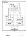
図2は、機器制御装置10の構成を概略的に示すブロック図である。
機器制御装置10は、通信部111と、制御部110と、記憶部113とを有する。本実施の形態では、機器制御装置10は、さらに操作表示部117を有する。ただし、操作表示部117は、機器制御装置10の外部において機器制御装置10と通信可能に接続されていてもよい。
FIG. 2 is a block diagram schematically showing the configuration of the device control apparatus 10.
The device control apparatus 10 includes a communication unit 111, a control unit 110, and a storage unit 113. In the present embodiment, the device control apparatus 10 further includes an operation display unit 117. However, the operation display unit 117 may be communicably connected to the device control apparatus 10 outside the device control apparatus 10.

操作表示部117は、表示部117aと、操作部117bとを有する。表示部117aには、被制御機器20の機器状態情報及び被制御機器20に入力する操作指示、記憶部113に格納された情報などが表示される。ユーザは、操作部117b(例えば、ボタン)を用いて、機器制御装置10内(例えば、制御部110)に操作指示(制御内容)などを入力することができる。操作表示部117がタッチパネルの場合、表示部117aと操作部117bとが一体に構成されてもよい。   The operation display unit 117 includes a display unit 117a and an operation unit 117b. The display unit 117a displays device status information of the controlled device 20, operation instructions input to the controlled device 20, information stored in the storage unit 113, and the like. The user can input an operation instruction (control content) or the like into the device control apparatus 10 (for example, the control unit 110) using the operation unit 117b (for example, a button). When the operation display unit 117 is a touch panel, the display unit 117a and the operation unit 117b may be configured integrally.

制御部110は、情報取得部112と、情報更新部114と、制御内容選択部115(制御命令決定部)と、命令送信部116とを有する。制御部110は、通信部111を介して、複数の被制御機器20のうちの少なくともいずれかを制御する機器制御命令を送信する。   The control unit 110 includes an information acquisition unit 112, an information update unit 114, a control content selection unit 115 (control command determination unit), and a command transmission unit 116. The control unit 110 transmits a device control command for controlling at least one of the plurality of controlled devices 20 via the communication unit 111.

通信部111は、複数の被制御機器20及びデータベース30と通信を行う。例えば、通信部111は、被制御機器20に対して機器制御命令を送信したり、被制御機器20から機器状態情報を含む各種情報を受信したりする。さらに、通信部111は、データベース30に情報取得要求を送信し、情報を受信することができる。通信に用いる媒体は、例えば、前述のとおり、Ethernet(登録商標)、無線LAN又は赤外線通信等が挙げられる。   The communication unit 111 communicates with the plurality of controlled devices 20 and the database 30. For example, the communication unit 111 transmits a device control command to the controlled device 20 or receives various types of information including device state information from the controlled device 20. Further, the communication unit 111 can transmit an information acquisition request to the database 30 and receive information. Examples of the medium used for communication include Ethernet (registered trademark), wireless LAN, and infrared communication as described above.

情報取得部112は、通信部111を介して、被制御機器20及びデータベース30から情報を取得する。情報取得部112が被制御機器20から取得する情報には、機器状態情報が含まれる。また、情報取得部112がデータベース30から取得する情報には、連動制御ルール情報、状態タグ情報更新ルール情報が含まれる。なお、情報取得部112は、取得された情報を記憶部113に記憶させる。   The information acquisition unit 112 acquires information from the controlled device 20 and the database 30 via the communication unit 111. Information acquired by the information acquisition unit 112 from the controlled device 20 includes device state information. The information acquired by the information acquisition unit 112 from the database 30 includes interlocking control rule information and state tag information update rule information. The information acquisition unit 112 causes the storage unit 113 to store the acquired information.

記憶部113には、情報が格納される。例えば、記憶部113は、機器情報テーブル121、グループ情報テーブル122、連動制御ルールテーブル123、及び状態タグ情報更新ルールテーブル124の4種類のテーブル形式の情報を記憶する。   Information is stored in the storage unit 113. For example, the storage unit 113 stores information in four types of table formats: a device information table 121, a group information table 122, an interlock control rule table 123, and a status tag information update rule table 124.

情報取得部112が取得した機器状態情報は、機器情報テーブル121の項目の一つとして記憶部113に記憶される。また、情報取得部112が取得した連動制御ルール情報及び状態タグ情報更新ルール情報は、それぞれ連動制御ルールテーブル123及び状態タグ情報更新ルールテーブル124の項目の一つとして記憶部113に記憶される。記憶部113が記憶する各種情報の詳細については後述する。   The device status information acquired by the information acquisition unit 112 is stored in the storage unit 113 as one item of the device information table 121. Further, the interlock control rule information and the state tag information update rule information acquired by the information acquisition unit 112 are stored in the storage unit 113 as one of items of the interlock control rule table 123 and the state tag information update rule table 124, respectively. Details of various information stored in the storage unit 113 will be described later.

情報更新部114は、記憶部113に記憶されている情報の更新を行う。例えば、情報更新部114は、機器情報テーブル121における機器状態情報121dに基づいて、機器情報テーブル121における状態タグ情報121fを更新する。情報更新部114が行う情報の更新の詳細については後述する。   The information update unit 114 updates information stored in the storage unit 113. For example, the information update unit 114 updates the state tag information 121 f in the device information table 121 based on the device state information 121 d in the device information table 121. Details of the information update performed by the information update unit 114 will be described later.

制御内容選択部115は、機器制御装置10から被制御機器20に機器制御命令を送信するか否かの判断を行なう。判断の結果、機器制御命令を送信する場合は、制御内容選択部115は、機器制御命令を送信する対象(送信先)の被制御機器20を選択し、さらに、送信する機器制御命令(制御内容)を選択する。制御内容選択部115が行う判断及び選択の詳細については後述する。   The control content selection unit 115 determines whether or not to transmit a device control command from the device control apparatus 10 to the controlled device 20. As a result of the determination, when a device control command is transmitted, the control content selection unit 115 selects a controlled device 20 that is a target (transmission destination) to which the device control command is transmitted, and further transmits a device control command (control content) to be transmitted. ) Is selected. Details of determination and selection performed by the control content selection unit 115 will be described later.

命令送信部116は、制御内容選択部115によって選択された機器制御命令(制御内容)を、通信部111を介して被制御機器20に送信する。機器制御命令の送信先は、制御内容選択部115によって選択された送信対象の被制御機器20である。   The command transmission unit 116 transmits the device control command (control content) selected by the control content selection unit 115 to the controlled device 20 via the communication unit 111. The transmission destination of the device control command is the transmission target controlled device 20 selected by the control content selection unit 115.

次に、記憶部113が記憶する各種情報について説明する。   Next, various information stored in the storage unit 113 will be described.

まず、図3を用いて、機器情報テーブル121について説明する。
図3は、複数の被制御機器20の各々に関する情報が格納された機器情報テーブル121(テーブル1)を示す図である。
First, the device information table 121 will be described with reference to FIG.
FIG. 3 is a diagram illustrating a device information table 121 (table 1) in which information on each of the plurality of controlled devices 20 is stored.

機器情報テーブル121は、複数の被制御機器20の各々についての、機器ID121a、機器種別121b、機器名称121c、機器状態情報121d、グループID情報121e、及び状態タグ情報121fの項目を有する。機器ID121a、機器種別121b、機器名称121c、機器状態情報121d、グループID情報121e、及び状態タグ情報121fに格納される情報は、各被制御機器20に関連付けられる。   The device information table 121 includes items of device ID 121a, device type 121b, device name 121c, device state information 121d, group ID information 121e, and state tag information 121f for each of the plurality of controlled devices 20. Information stored in the device ID 121a, device type 121b, device name 121c, device status information 121d, group ID information 121e, and status tag information 121f is associated with each controlled device 20.

機器ID121aには、複数の被制御機器20の各々を一意に識別するための情報が格納される。例えば、機器ID121aは、番号、文字列、又はこれらの組み合わせで表される。本実施の形態では、機器ID121aは、被制御機器20に付与されたIP(Internet Protocol)アドレスによって表される。例えば、機器ID121aは、機器制御装置10によって自動的に割り振られる。この場合、機器制御装置10は、被制御機器20が保持している固有の情報を取得し、取得された情報に基づいて機器ID121aを生成してもよい。さらに、機器ID121aは、ユーザによって手動で設定されてもよい。   Information for uniquely identifying each of the plurality of controlled devices 20 is stored in the device ID 121a. For example, the device ID 121a is represented by a number, a character string, or a combination thereof. In the present embodiment, the device ID 121a is represented by an IP (Internet Protocol) address assigned to the controlled device 20. For example, the device ID 121a is automatically assigned by the device control apparatus 10. In this case, the device control apparatus 10 may acquire unique information held by the controlled device 20 and generate the device ID 121a based on the acquired information. Furthermore, the device ID 121a may be manually set by the user.

機器種別121bには、被制御機器20の種別を表す情報が格納される。被制御機器20の種別(機器種別)とは、例えば、エアコン、テレビ、又は照明などの、機器制御装置10よって遠隔制御される機器の種類を示す。複数の被制御機器20のうち、機器種別121bの欄に同じ情報が格納されている被制御機器20は、互いに同一又は類似の制御内容によって制御されることが期待される。機器種別121bには“エアコン”、“テレビ”といった可読性のある文字列の形式の情報が格納されてもよいし、種別ごとに割り振られた符号の形式の情報が格納されてもよい。   Information representing the type of the controlled device 20 is stored in the device type 121b. The type (device type) of the controlled device 20 indicates the type of device that is remotely controlled by the device control apparatus 10 such as an air conditioner, a television, or lighting. Of the plurality of controlled devices 20, the controlled devices 20 in which the same information is stored in the column of the device type 121b are expected to be controlled by the same or similar control contents. The device type 121b may store readable character string information such as “air conditioner” and “television”, or may store code format information assigned to each type.

機器名称121cには、ユーザによって識別されやすいように付与された被制御機器20の名称(機器名称)が格納される。例えば、複数の被制御機器20のうちの、第1のエアコン20Aに機器名称“リビングのエアコン”が付与され、第2のエアコン20Bに機器名称“寝室のエアコン”が付与される。これにより、ユーザは、複数のエアコンを識別しやすくなる。機器名称121cは、ユーザによって手動で設定されてもよいし、機器制御装置10が機器種別121b等の情報に基づいて自動的に設定してもよい。   In the device name 121c, the name (device name) of the controlled device 20 assigned so as to be easily identified by the user is stored. For example, of the plurality of controlled devices 20, the device name “living air conditioner” is assigned to the first air conditioner 20A, and the device name “bedroom air conditioner” is assigned to the second air conditioner 20B. Thereby, the user can easily identify a plurality of air conditioners. The device name 121c may be set manually by the user, or may be automatically set by the device control apparatus 10 based on information such as the device type 121b.

機器状態情報121dには、被制御機器20の状態(機器状態)を示す情報(機器状態情報)が格納される。機器状態情報121dに格納される情報は、情報取得部112によって被制御機器20から取得された情報に基づいて更新される。   Information (device state information) indicating the state (device state) of the controlled device 20 is stored in the device state information 121d. The information stored in the device status information 121d is updated based on the information acquired from the controlled device 20 by the information acquisition unit 112.

機器状態情報は、例えば、電源、運転モード、又は室温などの被制御機器20の動作状態又は動作の種類を示す動作情報と、電源のオンオフ(“入”又は“切”)、エアコンの設定(“暖房”又は“冷房”)などの動作情報の値(動作パラメータ)を示すパラメータ情報とを含む。機器状態情報121dには、動作情報と、動作情報に対応するパラメータ情報との組み合わせが格納される。機器状態情報121dに格納される情報は、被制御機器20の種類によって異なる。   The device state information includes, for example, operation information indicating the operation state or type of operation of the controlled device 20 such as power source, operation mode, or room temperature, power on / off (“on” or “off”), and air conditioner settings ( Parameter information indicating a value (operation parameter) of operation information such as “heating” or “cooling”). The device state information 121d stores a combination of operation information and parameter information corresponding to the operation information. The information stored in the device status information 121d varies depending on the type of the controlled device 20.

1つの被制御機器20について、複数の機器状態情報が機器状態情報121dに格納されてもよい。例えば、No.1の機器状態情報121dには、複数の機器状態情報として、電源及び運転モードが格納されている。   For one controlled device 20, a plurality of pieces of device state information may be stored in the device state information 121d. For example, no. One device status information 121d stores a power source and an operation mode as a plurality of device status information.

機器状態情報121dに格納される、動作情報及びパラメータ情報は、“運転モード”又は“暖房”などのように可読性のある文字列の形式で格納されてもよいし、種別又は値ごとに割り振られた符号の形式で格納されてもよい。   The operation information and parameter information stored in the device status information 121d may be stored in the form of a readable character string such as “operation mode” or “heating”, and are allocated for each type or value. It may be stored in the form of a code.

グループID情報121eには、各被制御機器20が所属するグループ(割り当てグループ)を示す情報(グループID)が格納される。グループIDは、例えば、番号、文字列、又はこれらの組み合わせで表される。本実施の形態では、グループIDとして、通し番号が用いられる。例えば、グループIDは、各被制御機器20が設置される位置に基づいて付与される。同じ部屋に設置される被制御機器20は、互いに同じグループとなるように、各被制御機器20にグループIDが付与されることが望ましい。1つの発信源から発信される音波又は赤外線が到達する範囲内に設置された被制御機器20が互いに同一のグループとなるように、各被制御機器20にグループIDが付与されてもよい。グループID情報121eは、ユーザにより手動で設定することができる。ただし、機器制御装置10によって自動設定されてもよい。   The group ID information 121e stores information (group ID) indicating a group (assignment group) to which each controlled device 20 belongs. The group ID is represented by, for example, a number, a character string, or a combination thereof. In the present embodiment, a serial number is used as the group ID. For example, the group ID is given based on the position where each controlled device 20 is installed. It is desirable that a group ID is assigned to each controlled device 20 so that the controlled devices 20 installed in the same room are in the same group. A group ID may be assigned to each controlled device 20 so that the controlled devices 20 installed within a range where sound waves or infrared rays transmitted from one transmission source reach the same group. The group ID information 121e can be set manually by the user. However, it may be automatically set by the device control apparatus 10.

状態タグ情報121fには、被制御機器20(第1の被制御機器)又はその被制御機器20の周辺に設置された他の被制御機器20(第2の被制御機器)の使用状態及び使用目的、並びにユーザの位置及び動作などの、その被制御機器20(第1の被制御機器)について関連性があると推定される情報を示す状態タグ(タグ)が格納される。また、一つの被制御機器20についての状態タグ情報121fの欄には、複数の状態タグが格納されていてもよいし、状態タグが一つも格納されなくてもよい。   The status tag information 121f includes the usage state and usage of the controlled device 20 (first controlled device) or another controlled device 20 (second controlled device) installed around the controlled device 20. A state tag (tag) indicating information estimated to be relevant to the controlled device 20 (first controlled device), such as the purpose and the position and operation of the user, is stored. Also, a plurality of status tags may be stored in the status tag information 121f column for one controlled device 20, or no status tag may be stored.

例えば、ヒートポンプ給湯器20I(第1の被制御機器)が使用されている場合、ヒートポンプ給湯器20Iは、入浴を目的として使用されている状態であることが推定されるため、ヒートポンプ給湯器20Iに対応する状態タグ情報121fの欄に状態タグ“入浴中”が格納される。さらに、浴室に設置された第1の照明20Eは、ヒートポンプ給湯器20Iと同じ部屋又は近接する位置に設置されていることが推定されるので、ヒートポンプ給湯器20Iと同様に、状態タグ“入浴中”が、第1の照明20Eに対応する状態タグ情報121fの欄に格納される。   For example, when the heat pump water heater 20I (first controlled device) is used, the heat pump water heater 20I is estimated to be in a state of being used for bathing. The status tag “in bathing” is stored in the corresponding status tag information 121 f column. Furthermore, since it is presumed that the first lighting 20E installed in the bathroom is installed in the same room as the heat pump water heater 20I or in a close position, the state tag “in bathing” is assumed as in the heat pump water heater 20I. "Is stored in the field of the status tag information 121f corresponding to the first illumination 20E.

状態タグ情報121fには、“入浴中”又は“調理中”などのように可読性のある文字列の形式の情報が格納されてもよいし、状態タグごとに割り振られた符号の形式の情報が格納されてもよい。状態タグ情報121fに格納され得る情報(状態タグ)の種類は、予め与えられているものとする。本実施の形態では、状態タグ情報121fに格納される状態タグは、後述する状態タグ情報更新ルールテーブル124によって与えられる。   The state tag information 121f may store information in the form of a readable character string such as “during bathing” or “during cooking”, or information on the code format assigned to each state tag. It may be stored. It is assumed that the type of information (status tag) that can be stored in the status tag information 121f is given in advance. In the present embodiment, the status tag stored in the status tag information 121f is given by the status tag information update rule table 124 described later.

状態タグ情報121fの更新は、機器情報テーブル121に格納されている情報、及び後述する状態タグ情報更新ルールテーブル124に格納されている情報に基づいて情報更新部114によって実行される。   The status tag information 121f is updated by the information update unit 114 based on information stored in the device information table 121 and information stored in a status tag information update rule table 124 described later.

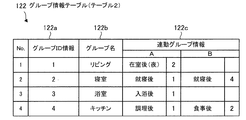
図4は、複数のグループ(グループID)に関する情報が格納されたグループ情報テーブル122(テーブル2)を示す図である。   FIG. 4 is a diagram showing a group information table 122 (table 2) in which information on a plurality of groups (group IDs) is stored.

グループ情報テーブル122は、複数のグループ(グループID)の各々についての、グループID情報122a、グループ名122b、及び連動グループ情報122cの項目を有する。   The group information table 122 includes items of group ID information 122a, group name 122b, and interlocking group information 122c for each of a plurality of groups (group IDs).

グループID情報122aには、グループIDが格納される。本実施の形態では、新しいグループが設定される度に、機器制御装置10が新たなグループに関連付けられたグループIDが割り当てられる。   The group ID information 122a stores a group ID. In the present embodiment, every time a new group is set, the device control apparatus 10 is assigned a group ID associated with the new group.

グループ名122bには、グループIDに関連付けられたグループの名称が格納される。具体的には、グループ名122bに格納される情報は、ユーザが識別しやすいように、例えば、文字列によって付与されるグループの名称である。例えば、1つのグループとしての部屋の名称は、“リビング”又は“キッチン”などの文字列によって示される。本実施の形態では、グループ名122bは、ユーザによって手動で設定される。   The group name 122b stores the name of the group associated with the group ID. Specifically, the information stored in the group name 122b is, for example, a group name given by a character string so that the user can easily identify the information. For example, the name of a room as one group is indicated by a character string such as “living room” or “kitchen”. In the present embodiment, the group name 122b is manually set by the user.

連動グループ情報122cには、第1のグループに属する被制御機器20の状態タグと、第2のグループを示すグループIDとが格納される。これらの情報は互いに関連付けられ、1組の情報として格納される。連動グループ情報122cの欄に格納される1組の情報は、互いに関連性の高い組み合わせを示す。例えば、第1のグループに属する被制御機器20(例えば、第1の被制御機器)に第1の状態タグが付与されている状態において、第2のグループに属する他の被制御機器20(例えば、第2の被制御機器)が使用される頻度が高い場合に、第1のグループ(例えば、グループID=1)、第1の状態タグ、及び第2のグループ(例えば、グループID=2)は、互いに関連性が高いとみなし、この1組の情報が連動グループ情報122cの欄に格納される。   The interlocking group information 122c stores a status tag of the controlled device 20 belonging to the first group and a group ID indicating the second group. These pieces of information are associated with each other and stored as a set of information. One set of information stored in the column of the interlocking group information 122c indicates a highly relevant combination. For example, in a state where the first status tag is assigned to the controlled device 20 (for example, the first controlled device) belonging to the first group, the other controlled device 20 (for example, the second group) , The second controlled device) is frequently used, the first group (for example, group ID = 1), the first status tag, and the second group (for example, group ID = 2). Are considered highly related to each other, and this set of information is stored in the column of the interlocking group information 122c.

図4に示される例では、グループ情報テーブル122のNo.3の連動グループ情報122cの欄に格納されている情報は、第1のグループとしてのグループ3(グループID=3)に属する被制御機器20に付与される状態タグ“入浴後”と、第2のグループとしてのグループ1(グループID=1)とが、互いに関連性が高いことを示す。   In the example shown in FIG. The information stored in the column of the third interlocking group information 122c includes the status tag “after bathing” given to the controlled device 20 belonging to the group 3 (group ID = 3) as the first group, the second It is shown that the group 1 (group ID = 1) as a group is highly related to each other.

連動グループ情報122cには、1つのグループにつき、複数の組からなる情報が格納されていてもよく、1組の情報も格納されなくてもよい。図4に示される例では、グループID情報122aが“2”及び“4”である項目の連動グループ情報122cに、2組の情報がそれぞれ格納されている。   The interlocking group information 122c may store information consisting of a plurality of sets per group, and may not store a set of information. In the example shown in FIG. 4, two sets of information are stored in the interlocking group information 122c of items whose group ID information 122a is “2” and “4”.

連動グループ情報122cは、機器情報テーブル121に格納されている情報の履歴に基づいて、情報更新部114により更新される。   The interlocking group information 122c is updated by the information updating unit 114 based on the history of information stored in the device information table 121.

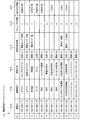
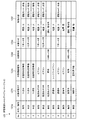
図5は、機器制御命令(制御命令)と、機器制御命令の送信可否を判断するための複数の判断条件との組み合わせが格納された連動制御ルールテーブル(テーブル3)を示す図である。   FIG. 5 is a diagram illustrating an interlock control rule table (table 3) in which combinations of device control commands (control commands) and a plurality of determination conditions for determining whether or not device control commands can be transmitted are stored.

連動制御ルールテーブル123は、有効無効情報123a、対象状態タグ123b、対象機器種別123c、対象時刻123d、対象日付123e、及び制御内容123fの項目を有する。これらの項目のうち、有効無効情報123a、対象状態タグ123b、対象機器種別123c、対象時刻123d、及び対象日付123eは、判断条件(送信条件)である。言い換えると、有効無効情報123a、対象状態タグ123b、対象機器種別123c、対象時刻123d、及び対象日付123eは、機器制御命令の送信の可否を決定する情報が格納される項目である。制御内容123fは、判断条件に基づいて送信される機器制御命令の内容を示す情報である。   The interlock control rule table 123 includes items of valid / invalid information 123a, target status tag 123b, target device type 123c, target time 123d, target date 123e, and control content 123f. Among these items, the valid / invalid information 123a, the target state tag 123b, the target device type 123c, the target time 123d, and the target date 123e are determination conditions (transmission conditions). In other words, the valid / invalid information 123a, the target state tag 123b, the target device type 123c, the target time 123d, and the target date 123e are items that store information that determines whether or not a device control command can be transmitted. The control content 123f is information indicating the content of the device control command transmitted based on the determination condition.

対象状態タグ123b、対象機器種別123c、対象時刻123d、対象日付123e、及び制御内容123fは、情報取得部112によってデータベース30から取得される。   The target status tag 123b, the target device type 123c, the target time 123d, the target date 123e, and the control content 123f are acquired from the database 30 by the information acquisition unit 112.

有効無効情報123aには、連動制御ルールテーブル123に格納された判断条件が有効であるか又は無効であるかを表す情報(“有効”又は“無効”)が格納される。判断条件が有効である場合、“有効”が有効無効情報123aに格納され、判断条件が無効である場合、有効無効情報123aに“無効”が格納される。有効無効情報123aに格納される情報(“有効”及び“無効”)は、可読性のある文字列の形式で格納されてもよいし、符号の形式で格納されてもよい。有効無効情報123aに格納される情報は、ユーザが手動で設定することができる。有効無効情報123aが“無効”である場合は、判断条件は常に満たさないことを意味する。   The valid / invalid information 123a stores information (“valid” or “invalid”) indicating whether the determination condition stored in the interlocking control rule table 123 is valid or invalid. When the determination condition is valid, “valid” is stored in the valid / invalid information 123a, and when the determination condition is invalid, “invalid” is stored in the valid / invalid information 123a. Information stored in the valid / invalid information 123a (“valid” and “invalid”) may be stored in the form of a readable character string or may be stored in the form of a code. Information stored in the valid / invalid information 123a can be manually set by the user. When the valid / invalid information 123a is “invalid”, it means that the determination condition is not always satisfied.

対象状態タグ123bは、状態タグに関する判断条件を表す情報である。対象状態タグ123bには、いずれかの状態タグが格納される。対象状態タグ123bは、後述する機器制御処理において、被制御機器20に付与されたいずれかの状態タグと、対象状態タグ123bに格納された状態タグとが一致するかを判定する際に用いられる。   The target state tag 123b is information representing a determination condition regarding the state tag. One of the status tags is stored in the target status tag 123b. The target state tag 123b is used to determine whether any of the state tags assigned to the controlled device 20 matches the state tag stored in the target state tag 123b in the device control process described later. .

対象機器種別123cは、機器種別に関する判断条件を表す情報である。対象機器種別123cには、いずれかの機器種別が格納される。対象機器種別123cは、後述する機器制御処理において、判断対象の被制御機器20の機器種別と、対象機器種別123cに格納されている機器種別とが一致するかを判定する際に用いられる。   The target device type 123c is information representing a determination condition regarding the device type. One of the device types is stored in the target device type 123c. The target device type 123c is used when determining whether the device type of the controlled device 20 to be determined matches the device type stored in the target device type 123c in the device control process described later.

対象時刻123dは、時刻に関する判断条件を表す情報である。対象時刻123dには、判断条件としての時刻又は時間間隔が格納される。例えば、対象時刻123dには時間間隔(開始時刻及び終了時刻)が格納される。対象時刻123dは、後述する機器制御処理において、判断時の時刻(現在時刻)が、対象時刻123dに格納された時間間隔の範囲内か判定する際に用いられる。対象時刻123dには、情報が格納されなくてもよい。対象時刻123dに情報が格納されていない場合は、時刻又は時間間隔に関する判断条件は常に満たされていることを示す。   The target time 123d is information representing a determination condition regarding time. The target time 123d stores a time or time interval as a determination condition. For example, a time interval (start time and end time) is stored in the target time 123d. The target time 123d is used when determining whether the time at the time of determination (current time) is within the time interval stored in the target time 123d in the device control process described later. Information may not be stored in the target time 123d. If no information is stored at the target time 123d, it indicates that the determination condition regarding the time or the time interval is always satisfied.

対象日付123eは、日付に関する判断条件を表す情報である。対象日付123eには、日付又は期間(開始日及び終了日)が格納される。対象日付123eは、後述する機器制御処理において、判断時の日付が、対象日付123eに格納された期間の範囲内か判定する際に用いられる。対象日付123eには情報が格納されなくてもよい。対象日付123eに情報が格納されていない場合は、日付に関する判断条件は常に満たされていることを示す。   The target date 123e is information representing a determination condition regarding the date. The target date 123e stores a date or a period (start date and end date). The target date 123e is used when determining whether the date at the time of determination is within the range of the period stored in the target date 123e in the device control process described later. Information may not be stored in the target date 123e. If no information is stored in the target date 123e, it indicates that the determination condition regarding the date is always satisfied.

制御内容123fは、連動制御ルールテーブル123に格納された判断条件が満たされた場合に送信される機器制御命令の内容を示す情報である。すなわち、制御内容123fには、制御内容が格納される。制御内容123fに格納される内容(機器制御命令)は、機器種別によって異なる。制御内容123fには、複数の機器制御命令が格納されてもよい。制御内容123fに複数の機器制御命令が格納されている場合は、各機器制御命令が順に送信されることを意味する。例えば、連動制御ルールテーブル123のNo.1の制御内容123fの欄には、2つの機器制御命令“電源:入”及び“運転モード:送風”が格納されている。   The control content 123f is information indicating the content of the device control command transmitted when the determination condition stored in the interlocking control rule table 123 is satisfied. That is, the control content is stored in the control content 123f. The content (device control command) stored in the control content 123f differs depending on the device type. A plurality of device control commands may be stored in the control content 123f. When a plurality of device control commands are stored in the control content 123f, it means that each device control command is transmitted in order. For example, the No. of the interlock control rule table 123. In the column of 1 control content 123f, two device control commands “power supply: on” and “operation mode: air blowing” are stored.

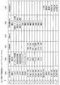
図6は、被制御機器20(状態タグ情報121f)に付与される付与状態タグと、付与状態タグを付与するための複数の判断条件との組み合わせが格納された状態タグ情報更新ルールテーブル(テーブル4)を示す図である。   FIG. 6 shows a status tag information update rule table (table) in which combinations of grant status tags given to the controlled device 20 (status tag information 121f) and a plurality of determination conditions for granting grant status tags are stored. It is a figure which shows 4).

状態タグ情報更新ルールテーブル124は、付与状態タグ124a、対象機器種別124b、対象時刻124c、対象日付124d、対象機器状態124e、及び対象状態タグ124fの項目を有する。   The status tag information update rule table 124 includes items of a grant status tag 124a, a target device type 124b, a target time 124c, a target date 124d, a target device status 124e, and a target status tag 124f.

状態タグ情報更新ルールテーブル124において、付与状態タグと判断条件との組み合わせは2通りである。1つの組み合わせは、付与状態タグ124a、対象機器種別124b、対象時刻124c、対象日付124d、及び対象機器状態124eの組み合わせである。もう1つの組み合わせは、付与状態タグ124a及び対象状態タグ124fの組み合わせである。   In the status tag information update rule table 124, there are two combinations of the grant status tag and the determination condition. One combination is a combination of an assignment state tag 124a, a target device type 124b, a target time 124c, a target date 124d, and a target device state 124e. Another combination is a combination of the assigned state tag 124a and the target state tag 124f.

付与状態タグ124a、対象機器種別124b、対象時刻124c、対象日付124d、対象機器状態124e、及び対象状態タグ124fは、情報取得部112によってデータベース30から取得される。   The grant status tag 124a, the target device type 124b, the target time 124c, the target date 124d, the target device status 124e, and the target status tag 124f are acquired from the database 30 by the information acquisition unit 112.

付与状態タグ124aは、判断条件を満たした場合に被制御機器20(状態タグ情報121f)に付与される状態タグを表す情報である。すなわち、付与状態タグ124aには、情報更新部114によって被制御機器20に付与される状態タグのいずれかが格納される。   The assignment state tag 124a is information representing a state tag assigned to the controlled device 20 (state tag information 121f) when the determination condition is satisfied. In other words, any of the status tags given to the controlled device 20 by the information update unit 114 is stored in the grant status tag 124a.

対象機器種別124bは、機器種別に関する判断条件を表す情報である。対象機器種別124bには、機器種別のいずれかが格納される。対象機器種別124bは、後述する状態タグの付与判断処理において、判断対象の被制御機器20の機器種別と、対象機器種別124bに格納されている機器種別とが一致するか判断する際に用いられる。   The target device type 124b is information representing a determination condition regarding the device type. One of the device types is stored in the target device type 124b. The target device type 124b is used when determining whether the device type of the controlled device 20 to be determined matches the device type stored in the target device type 124b in the state tag addition determination process described later. .

対象時刻124cは、時刻に関する判断条件を表す情報である。対象時刻124cには、時刻が格納される。判断条件としての時刻又は時間間隔が格納される。例えば、対象時刻124cには時間間隔(開始時刻及び終了時刻)が格納される。対象時刻124cは、後述する状態タグの付与判断処理において、判断時の時刻(現在時刻)が、対象時刻124cに格納された時間間隔の範囲内か判定する際に用いられる。対象時刻124cには、情報が格納されなくてもよい。対象時刻123dに情報が格納されていない場合は、時刻又は時間間隔に関する判断条件は常に満たされていることを示す。   The target time 124c is information representing a determination condition regarding time. The time is stored in the target time 124c. The time or time interval as a judgment condition is stored. For example, a time interval (start time and end time) is stored in the target time 124c. The target time 124c is used when determining whether the time at the time of determination (current time) is within the range of the time interval stored in the target time 124c in the state tag addition determination process described later. Information may not be stored in the target time 124c. If no information is stored at the target time 123d, it indicates that the determination condition regarding the time or the time interval is always satisfied.

対象日付124dは、日付に関する判断条件を表す情報である。対象日付124dには、日付又は期間(開始日及び終了日)が格納される。対象日付124dは、後述する状態タグの付与判断処理において、判断時の日付が、対象日付124dに格納された期間の範囲内か判定する際に用いられる。対象日付124dには情報が格納されなくてもよい。対象日付124dに情報が格納されていない場合は、日付に関する判断条件は常に満たされていることを示す。   The target date 124d is information representing a determination condition regarding the date. A date or a period (start date and end date) is stored in the target date 124d. The target date 124d is used to determine whether the date at the time of determination is within the range of the period stored in the target date 124d in the state tag addition determination process described later. Information may not be stored in the target date 124d. When no information is stored in the target date 124d, it indicates that the determination condition regarding the date is always satisfied.

対象機器状態124eは、被制御機器20の状態(機器状態)に関する判断条件を表す情報である。対象機器状態124eには、状態タグを付与するための判断条件としての機器状態のいずれかが格納される。対象機器状態124eは、後述する状態タグの付与判断処理において、判断対象の被制御機器20の機器状態と、対象機器状態124eに格納されている機器状態とが一致するか判定する際に用いられる。対象機器状態124eには、複数の機器状態が格納されていてもよい。対象機器状態124eに複数の機器状態が格納されている場合は、対象機器状態124eに格納されている全ての機器状態が、判断対象の被制御機器20の機器状態と一致するか判定される。   The target device state 124e is information representing a determination condition regarding the state (device state) of the controlled device 20. The target device state 124e stores one of the device states as a determination condition for adding a state tag. The target device state 124e is used when determining whether the device state of the controlled device 20 to be determined matches the device state stored in the target device state 124e in the state tag assignment determination process described later. . A plurality of device states may be stored in the target device state 124e. When a plurality of device states are stored in the target device state 124e, it is determined whether all device states stored in the target device state 124e match the device state of the controlled device 20 to be determined.

対象状態タグ124fは、関連性が高いグループの被制御機器20に付与された状態タグに関する判断条件を表す情報である。対象状態タグ124fには、いずれかの状態タグが格納される。例えば、第1のグループに属する被制御機器20(例えば、第1の被制御機器)に第1の状態タグが付与されている状態において、第2のグループに属する他の被制御機器20(例えば、第2の被制御機器)が使用される頻度が高い場合に、第1の被制御機器20に第1の状態タグが付与されている状態における第1のグループと第2のグループとは互いに関連性が高いと判定される。関連性の判定は、グループ情報テーブル122に含まれる連動グループ情報122cに基づいて判定される。   The target state tag 124f is information representing a determination condition regarding the state tag given to the controlled devices 20 of the highly related group. One of the status tags is stored in the target status tag 124f. For example, in a state where the first status tag is assigned to the controlled device 20 (for example, the first controlled device) belonging to the first group, the other controlled device 20 (for example, the second group) When the frequency of the second controlled device) is high, the first group and the second group in the state where the first status tag is assigned to the first controlled device 20 are mutually It is determined that the relevance is high. The relevance is determined based on the interlocking group information 122c included in the group information table 122.

次に、機器制御システム1における連動制御処理の一例を説明する。   Next, an example of the interlock control process in the device control system 1 will be described.

機器制御装置10の記憶部113は、機器制御命令と、機器制御命令の送信の可否を決定する制御ルール情報とを格納する。制御ルール情報は、有効無効情報123a、対象状態タグ123b、対象機器種別123c、対象時刻123d、及び対象日付123eに格納された少なくとも1つの情報を含む。本実施の形態では、制御ルール情報は、複数の被制御機器20のうちの少なくとも1つの被制御機器20と関連付けられる情報であるタグ(すなわち、状態タグ情報121f及び対象状態タグ123bに格納される状態タグ)を含む。制御部110は、予め定められた時間が経過したときに、タグの情報(すなわち、状態タグの内容)を変更することができる。   The storage unit 113 of the device control apparatus 10 stores a device control command and control rule information that determines whether or not the device control command can be transmitted. The control rule information includes at least one piece of information stored in the valid / invalid information 123a, the target state tag 123b, the target device type 123c, the target time 123d, and the target date 123e. In the present embodiment, the control rule information is stored in a tag (that is, state tag information 121f and target state tag 123b) that is information associated with at least one controlled device 20 among the plurality of controlled devices 20. Status tag). The control unit 110 can change the tag information (that is, the contents of the status tag) when a predetermined time has elapsed.

制御部110(例えば、制御内容選択部115)は、機器制御命令の送信先の少なくとも1つの被制御機器20を、制御ルール情報に基づいて複数の被制御機器20の中から選択する。制御部110(例えば、命令送信部116)は、選択された被制御機器20に機器制御命令を送信する。被制御機器20は、機器制御装置10から機器制御命令を受信した場合、その機器制御命令に従って動作を行う。   The control unit 110 (for example, the control content selection unit 115) selects at least one controlled device 20 that is a transmission destination of the device control command from the plurality of controlled devices 20 based on the control rule information. The control unit 110 (for example, the command transmission unit 116) transmits a device control command to the selected controlled device 20. When the controlled device 20 receives a device control command from the device control apparatus 10, the controlled device 20 operates according to the device control command.

制御部110は、少なくとも1つの被制御機器20と、複数の状態タグのうちの特定の状態タグTg1とを関連付けた状態で状態タグTg1を記憶部113に格納する。制御部110は、状態タグTg1が関連付けられた被制御機器20に機器制御命令を送信する。これにより、状態タグTg1に関連付けられた被制御機器20に対する連動制御が自動的に行われる。   The control unit 110 stores the state tag Tg1 in the storage unit 113 in a state in which at least one controlled device 20 is associated with a specific state tag Tg1 among the plurality of state tags. The control unit 110 transmits a device control command to the controlled device 20 associated with the state tag Tg1. Thereby, the interlock control for the controlled device 20 associated with the state tag Tg1 is automatically performed.

状態タグTg1が第1の被制御機器20に関連付けられている状態において、制御部110は、第1の被制御機器20と第2の被制御機器20とが互いに関連性が高いと判断した場合、制御部110は、第1の被制御機器20及び第2の被制御機器20と、状態タグTg1とを関連付けた状態で状態タグTg1を記憶部113に格納する。制御部110は、状態タグTg1が関連付けられた被制御機器20に機器制御命令を送信するので、状態タグTg1に関連付けられた被制御機器20に対する連動制御が自動的に行われる。   When the state tag Tg1 is associated with the first controlled device 20, the control unit 110 determines that the first controlled device 20 and the second controlled device 20 are highly related to each other. The control unit 110 stores the state tag Tg1 in the storage unit 113 in a state where the first controlled device 20 and the second controlled device 20 are associated with the state tag Tg1. Since the control unit 110 transmits a device control command to the controlled device 20 associated with the state tag Tg1, the interlock control for the controlled device 20 associated with the state tag Tg1 is automatically performed.

複数の被制御機器20の各々は、複数のグループ(例えば、グループ1,2,3,及び4)のいずれかに分類されている。具体的には、複数の被制御機器20の各々は、複数のグループのうちのいずれのグループに分類されているかを示すグループ情報(すなわち、グループID情報121eに格納されるグループID)によって、複数のグループのうちのいずれかに分類され、グループ情報が記憶部113に格納されている。複数のグループのうちの1つのグループに分類された少なくとも1つの被制御機器20には、状態タグTg1が関連付けられた状態で状態タグTg1が記憶部113に格納されている。   Each of the plurality of controlled devices 20 is classified into one of a plurality of groups (for example, groups 1, 2, 3, and 4). Specifically, each of the plurality of controlled devices 20 includes a plurality of groups by group information (that is, a group ID stored in the group ID information 121e) indicating which group of the plurality of groups is classified. And group information is stored in the storage unit 113. The state tag Tg1 is stored in the storage unit 113 in a state in which the state tag Tg1 is associated with at least one controlled device 20 classified into one group of the plurality of groups.

複数のグループのうちの1つのグループに分類された1つの被制御機器20に状態タグTg1が関連付けられた状態で状態タグTg1が記憶部113に格納された場合、制御部110は、状態タグTg1と、その1つのグループに分類された全ての被制御機器とを関連付けた状態で状態タグTg1を記憶部113に格納する。制御部110は、状態タグTg1が関連付けられた被制御機器20に機器制御命令を送信するので、状態タグTg1に関連付けられた全ての被制御機器20(すなわち、同一のグループに属する全ての被制御機器20)に対する連動制御が自動的に行われる。   When the state tag Tg1 is stored in the storage unit 113 in a state in which the state tag Tg1 is associated with one controlled device 20 classified into one group among the plurality of groups, the control unit 110 includes the state tag Tg1. Then, the state tag Tg1 is stored in the storage unit 113 in a state in which all controlled devices classified into the one group are associated with each other. Since the control unit 110 transmits a device control command to the controlled device 20 associated with the state tag Tg1, all the controlled devices 20 associated with the state tag Tg1 (that is, all controlled devices belonging to the same group). The interlocking control for the device 20) is automatically performed.

機器制御システム1の運用を開始する前に、少なくとも1つの被制御機器20と状態タグTg1とが予め関連付けられた状態で状態タグTg1が記憶部113に格納されていてもよい。ユーザは、操作表示部117から制御ルール情報を入力することができる。したがって、ユーザが、操作表示部117に表示された制御ルール情報を参照しながら、操作表示部117を用いて少なくとも1つの被制御機器20と状態タグTg1とを関連付け、記憶部113に格納することができる。   Before starting the operation of the device control system 1, the state tag Tg1 may be stored in the storage unit 113 in a state in which at least one controlled device 20 and the state tag Tg1 are associated in advance. The user can input control rule information from the operation display unit 117. Therefore, the user associates at least one controlled device 20 with the state tag Tg1 using the operation display unit 117 while referring to the control rule information displayed on the operation display unit 117, and stores it in the storage unit 113. Can do.

複数の被制御機器20のうちの少なくとも2つの被制御機器20が、互いに異なる部屋に設置されている場合でも、制御部110は、機器制御命令の送信先の被制御機器20としてその少なくとも2つの被制御機器を選択し、選択された少なくとも2つの被制御機器に機器制御命令を送信することができる。したがって、被制御機器20の設置場所に関わらず、連動制御を行うことができる。   Even when at least two controlled devices 20 of the plurality of controlled devices 20 are installed in different rooms, the control unit 110 may transmit at least two of the controlled devices 20 to which the device control command is transmitted. A controlled device can be selected and a device control command can be transmitted to at least two selected controlled devices. Therefore, the interlock control can be performed regardless of the installation location of the controlled device 20.

次に、機器制御システム1における連動制御処理の詳細を、図を参照しながら説明する。   Next, details of the interlock control processing in the device control system 1 will be described with reference to the drawings.

本実施の形態では、連動制御処理は、以下の7つの処理を含む。
1.データベースからの情報取得処理
2.被制御機器の追加処理
3.グループ情報の編集処理
4.被制御機器の機器状態情報の取得処理
5.連動グループ情報の更新処理
6.状態タグ情報の更新処理
7.連動制御ルールの編集処理
8.制御内容の選択処理
In the present embodiment, the interlock control process includes the following seven processes.
1. 1. Information acquisition processing from database 2. Additional processing of controlled device 3. Group information editing process 4. Device status information acquisition processing of controlled device 5. Linked group information update processing 6. Status tag information update processing 7. Interlocking control rule editing process Control content selection process

1.データベースからの情報取得処理
データベース30からの情報取得処理では、情報取得部112が、通信部111を介して、データベース30から情報を取得し、記憶部113に記憶する。
1. Information Acquisition Processing from Database In information acquisition processing from the database 30, the information acquisition unit 112 acquires information from the database 30 via the communication unit 111 and stores it in the storage unit 113.

データベース30から取得される情報は、連動制御ルールテーブル123に格納される、対象状態タグ123b、対象機器種別123c、対象時刻123d、対象日付123e、制御内容123fと、状態タグ情報更新ルールテーブル124に格納される、付与状態タグ124a、対象機器種別124b、対象時刻124c、対象日付124d、対象機器状態124e、対象状態タグ124fである。   Information acquired from the database 30 is stored in the interlock control rule table 123 in the target status tag 123b, the target device type 123c, the target time 123d, the target date 123e, the control content 123f, and the status tag information update rule table 124. These are the grant status tag 124a, target device type 124b, target time 124c, target date 124d, target device status 124e, and target status tag 124f that are stored.

これらの情報の取得は、定期的に、例えば一日に一回などのタイミングで行う。このタイミング以外に、例えば、ユーザが指定したタイミングで行ってもよいし、また、データベース30に格納されている情報が更新された時に、データベース30が機器制御装置10に対して更新された旨を通知し、通知を受け取ったタイミングで、データベース30から情報を取得してもよい。   Such information is acquired periodically, for example, once a day. In addition to this timing, for example, it may be performed at a timing designated by the user, or when the information stored in the database 30 is updated, the fact that the database 30 is updated with respect to the device control apparatus 10. Information may be acquired from the database 30 at the timing of notification and reception of the notification.

2.被制御機器の追加処理
被制御機器の追加処理では、機器制御システム1に、新たに被制御機器20が追加された際に、追加された被制御機器20の情報を記憶部113に記憶する。
2. Controlled Device Addition Processing In the controlled device addition processing, when a controlled device 20 is newly added to the device control system 1, information on the added controlled device 20 is stored in the storage unit 113.

記憶部113に記憶される情報は、機器情報テーブル121に格納される、機器ID121a、機器種別121b、及び機器名称121cである。   Information stored in the storage unit 113 includes a device ID 121a, a device type 121b, and a device name 121c stored in the device information table 121.

機器ID121aは一意に識別可能な値を機器制御装置10が割り振ってもよいし、情報取得部112が被制御機器20から取得した情報に基づいて生成してもよい。また、機器ID121aは、ユーザにより手動で設定されてもよい。   The device ID 121 a may be assigned a uniquely identifiable value by the device control apparatus 10, or may be generated based on information acquired from the controlled device 20 by the information acquisition unit 112. The device ID 121a may be manually set by the user.

機器種別121bは、情報取得部112によって被制御機器20から取得され、機器情報テーブル121に格納される。   The device type 121 b is acquired from the controlled device 20 by the information acquisition unit 112 and stored in the device information table 121.

機器名称121cは、ユーザによって手動で設定されてもよいし、情報取得部112が機器種別121bに基づいて設定してもよい。   The device name 121c may be set manually by the user, or may be set by the information acquisition unit 112 based on the device type 121b.

これらの情報は、新たに被制御機器20が追加された際に格納される。新たに被制御機器20が追加されたことを機器制御装置10が認識するためには、例えば、追加された被制御機器20が定期的に自らの存在を機器制御装置10又は他の被制御機器20に通知してもよいし、情報取得部112が定期的に機器情報を取得する要求を、機器制御システム1のネットワーク内の不特定多数の機器に送信してもよい。   These pieces of information are stored when a new controlled device 20 is added. In order for the device control apparatus 10 to recognize that a new controlled device 20 has been newly added, for example, the added controlled device 20 periodically detects its own device control device 10 or other controlled device. 20 or the information acquisition unit 112 may periodically transmit a request for acquiring device information to an unspecified number of devices in the network of the device control system 1.

3.グループ情報の編集処理
グループ情報の編集処理では、機器情報テーブル121に格納されるグループID情報121eと、グループ情報テーブル122に格納されるグループID情報122a及びグループ名122bとに、新しい項目を追加したり、値を更新したりする。
3. Group Information Editing Process In the group information editing process, new items are added to the group ID information 121e stored in the device information table 121, the group ID information 122a and the group name 122b stored in the group information table 122. Or update the value.

機器情報テーブル121に格納されるグループID情報121eは、ユーザによって設定される。このとき、グループ情報テーブル122に格納されているグループID情報122aから一つ選択して設定する。ユーザがグループID情報122aを選択する際は、グループID情報122aを直接選択するのではなく、グループ名122bを選択してもよい。この時は、選択したグループ名122bに対応するグループID情報122aが、機器情報テーブル121に格納されるグループID情報121eに設定される。   The group ID information 121e stored in the device information table 121 is set by the user. At this time, one group ID information 122a stored in the group information table 122 is selected and set. When the user selects the group ID information 122a, the group name 122b may be selected instead of selecting the group ID information 122a directly. At this time, the group ID information 122a corresponding to the selected group name 122b is set in the group ID information 121e stored in the device information table 121.

グループ情報テーブル122に格納されるグループID情報122aは、ユーザが手動で設定してもよいし、グループ情報テーブル122に新たなグループID情報122aが格納される度に、機器制御装置10が一意に識別可能な値を割り振ってもよい。   The group ID information 122a stored in the group information table 122 may be set manually by the user, or each time the new group ID information 122a is stored in the group information table 122, the device control apparatus 10 is uniquely set. An identifiable value may be assigned.

グループ情報テーブル122に格納されるグループ名122bは、ユーザによって設定される。   The group name 122b stored in the group information table 122 is set by the user.

これらの情報の更新されるタイミングは、ユーザが設定操作を行った際に随時行われる。   The timing at which these pieces of information are updated is performed as needed when the user performs a setting operation.

4.被制御機器の機器状態情報の取得処理
被制御機器の機器状態情報の取得処理では、情報取得部112は、通信部111を介して被制御機器20から状態情報を取得し、記憶部113の機器情報テーブル121に記憶させる。
4). Device Status Information Acquisition Process of Controlled Device In the device status information acquisition process of the controlled device, the information acquisition unit 112 acquires status information from the controlled device 20 via the communication unit 111, and the device in the storage unit 113 The information is stored in the information table 121.

被制御機器20の状態情報の取得処理を行うタイミングは、例えば、1分おきといった頻度で定期的に行う。被制御機器20の機器状態が変化した時に、被制御機器20が変化した旨を機器制御装置10に通知し、そのタイミングで取得処理を行ってもよい。   The timing for acquiring the status information of the controlled device 20 is periodically performed at a frequency of every other minute, for example. When the device state of the controlled device 20 changes, the device control device 10 may be notified that the controlled device 20 has changed, and the acquisition process may be performed at that timing.

5.連動グループ情報の更新処理
連動グループ情報の更新処理では、情報更新部114は、グループ間の関連性の判断を行う。関連性の高いグループがあると判断された場合、第1のグループに属する被制御機器20に付与された状態タグと、その状態タグと関連性が高いと判断された第2のグループのグループIDとを記憶部113の連動グループ情報122cに格納する。
5. Linked Group Information Update Process In the linked group information update process, the information update unit 114 determines the relationship between groups. If it is determined that there is a highly related group, the status tag assigned to the controlled device 20 belonging to the first group and the group ID of the second group determined to be highly related to the status tag Are stored in the interlocking group information 122c of the storage unit 113.

関連性の判断は、例えば、第1のグループに属する被制御機器20(例えば、第1の被制御機器)に第1の状態タグが付与されている状態において、第2のグループに属する他の被制御機器20(例えば、第2の被制御機器)がユーザによって使用される頻度に基づいて判断される。   For example, in the state in which the first status tag is assigned to the controlled device 20 (for example, the first controlled device) that belongs to the first group, The determination is based on the frequency with which the controlled device 20 (for example, the second controlled device) is used by the user.

連動グループ情報の更新処理の具体的な手順を説明する。
情報更新部114は、予め、被制御機器20のそれぞれについて、電源などの機器状態が変化した回数を計測し、グループごとに和をとった値を少なくとも数日分保持しておく。説明のため、この値を計測時間で割ったものをグループ別全日操作頻度Fall(j)(jは、グループIDに対応する1以上の整数)とする。
A specific procedure for the update processing of linked group information will be described.
The information updating unit 114 previously measures the number of times the device state such as the power supply has changed for each controlled device 20, and holds a value obtained by summing each group for at least several days. For the sake of explanation, the value obtained by dividing this value by the measurement time is assumed to be the group-wide all-day operation frequency Fall (j) (j is an integer of 1 or more corresponding to the group ID).

さらに、情報更新部114は、あるグループ(第1のグループ)に含まれる被制御機器20にいずれかの状態タグ(tag)が付与されている間の、他のグループ(例えば、第2のグループ)に含まれる被制御機器20のそれぞれについて、電源などの機器状態が変化した回数を計測し、グループ(第2のグループ)ごとに和をとった値を保持する。この値を計測時間で割ったものをグループ別状態タグ別操作頻度Ftag(i,tag,j)とする。ここで、iは、第1のグループのグループIDに対応する1以上の整数であり、tagは、第1のグループに含まれる被制御機器20に付与された状態タグに対応し、jは、第2のグループのグループIDに対応する。   Furthermore, the information update unit 114 may add another group (for example, the second group) while one of the status tags (tags) is assigned to the controlled device 20 included in a certain group (first group). For each controlled device 20 included in (), the number of times the device state such as the power source is changed is measured, and a sum value is held for each group (second group). A value obtained by dividing this value by the measurement time is set as an operation frequency Ftag (i, tag, j) for each state tag for each group. Here, i is an integer equal to or greater than 1 corresponding to the group ID of the first group, tag corresponds to the status tag assigned to the controlled device 20 included in the first group, and j is Corresponds to the group ID of the second group.

Ftag(i,tag,j)/Fall(j)によって算出された値F1が、閾値F0以上である場合、情報更新部114は、第1のグループの被制御機器20に状態タグが付与されている間、第2のグループの被制御機器20が操作される頻度が高くなると判断し、特定の状態タグ(tag)に関連付けられた第1のグループの被制御機器20と、第2のグループ(第2のグループの被制御機器20)とは互いに関連性が高いと判断する。   When the value F1 calculated by Ftag (i, tag, j) / Fall (j) is equal to or greater than the threshold value F0, the information updating unit 114 adds the status tag to the controlled device 20 of the first group. The controlled device 20 of the first group associated with the specific status tag (tag) is determined to be operated frequently, and the second group ( It is determined that the second group of controlled devices 20) are highly related to each other.

情報更新部114は、第iのグループに属する被制御機器20の状態タグと、第jのグループを示すグループID“j”とを、第iのグループに対応する連動グループ情報122cの欄に追加する。   The information updating unit 114 adds the status tag of the controlled device 20 belonging to the i-th group and the group ID “j” indicating the j-th group to the column of the interlocking group information 122c corresponding to the i-th group. To do.

図4に示される例では、情報更新部114は、グループIDが“1”の被制御機器20に状態タグ“在室後(夜)”が付与されている間、グループIDが“2”の被制御機器20の被制御機器20が操作される頻度が高いと判断したので、グループID“1”と、状態タグ“在室後(夜)”と、グループID“2”とは、関連度が高いと判断し、グループID“1”の連動グループ情報122cの欄に、状態タグ“在室後(夜)”及びグループID“2”が格納されている。   In the example shown in FIG. 4, the information update unit 114 has the group ID “2” while the status tag “after occupancy (night)” is assigned to the controlled device 20 with the group ID “1”. Since it is determined that the controlled device 20 of the controlled device 20 is frequently operated, the group ID “1”, the status tag “after occupancy (night)”, and the group ID “2” And the status tag “after occupancy (night)” and the group ID “2” are stored in the column of the linked group information 122c of the group ID “1”.

また、情報更新部114は、値F1が、ある閾値(例えば20)を下回った場合に、対応する連動グループ情報122cに格納された情報をグループ情報テーブル122から削除してもよい。このときの閾値は、閾値F0とは別の値でもよい。また、値F1が、閾値を下回った場合に、対応する連動グループ情報122cからすぐに削除するのではなく、閾値を下回った状態が一定時間(例えば一週間)継続した場合に削除するようにしてもよい。   Moreover, the information update part 114 may delete the information stored in the corresponding interlocking | linkage group information 122c from the group information table 122, when the value F1 is less than a certain threshold value (for example, 20). The threshold value at this time may be a value different from the threshold value F0. In addition, when the value F1 falls below the threshold, it is not deleted immediately from the corresponding linked group information 122c, but is deleted when the state below the threshold continues for a certain time (for example, one week). Also good.

連動グループ情報の更新処理を行うタイミングは、機器状態が変化した回数の計測については、例えば、1分おきといった頻度で定期的に行う。もしくは、被制御機器の機器状態情報の取得処理により、機器情報テーブル121に格納されている情報が更新されたタイミングでおこなってもよい。また、閾値との比較に基づいて連動グループ情報122cに格納されている情報を更新する処理は、機器状態が変化した回数の計測と同時に行ってもよいし、一日に一度など、より少ない頻度で行ってもよい。   The timing for performing the update processing of the interlocking group information is periodically performed at a frequency of every other minute, for example, for measuring the number of times the device state has changed. Alternatively, it may be performed at the timing when the information stored in the device information table 121 is updated by the acquisition processing of the device status information of the controlled device. Further, the process of updating the information stored in the interlocking group information 122c based on the comparison with the threshold value may be performed simultaneously with the measurement of the number of times the device state has changed, or less frequently, such as once a day. You may go on.

6.状態タグ情報の更新処理
状態タグ情報の更新処理では、情報更新部114が、更新処理対象の被制御機器20に、状態タグの付与(追加)を行う。具体的には、情報更新部114は、機器情報テーブル121に格納されている情報と、状態タグ情報更新ルールテーブル124に格納されている情報とに基づいて、更新処理対象の被制御機器20に対応する機器情報テーブル121の状態タグ情報121fの欄に状態タグを格納する。
6). Status Tag Information Update Process In the status tag information update process, the information update unit 114 adds (adds) a status tag to the controlled device 20 to be updated. Specifically, the information update unit 114 determines whether the control target device 20 to be updated is based on the information stored in the device information table 121 and the information stored in the status tag information update rule table 124. The status tag is stored in the column of status tag information 121 f of the corresponding device information table 121.

図6に示される例では、例えば、レンジフードファン20Kの機器状態(電源)が“電源:入”である場合、状態タグ情報更新ルールテーブル124の対象機器状態124e(No.5の対象機器状態124e)に格納されている機器状態(電源:入)と一致しているので、条件を満たしている。したがって、情報更新部114は、レンジフードファン20Kが、対象機器状態124eに格納されている条件を満たすと判断し、機器情報テーブル121のレンジフードファン20Kに対応する状態タグ情報121fの欄に状態タグ“調理中”を格納する。   In the example shown in FIG. 6, for example, when the device state (power supply) of the range hood fan 20K is “power supply: on”, the target device state 124e (No. 5 target device state) of the state tag information update rule table 124. 124e) is in agreement with the device state (power: on) stored in, and therefore the condition is satisfied. Therefore, the information update unit 114 determines that the range hood fan 20K satisfies the condition stored in the target device state 124e, and the state is displayed in the column of the state tag information 121f corresponding to the range hood fan 20K in the device information table 121. The tag “cooking” is stored.

このようにして、ある被制御機器20に状態タグが付与された時に、情報更新部114は、状態タグが付与された被制御機器20とグループIDが等しい別の被制御機器20にも同じタグを付与してもよい。例えば、前記の例では、レンジフードファン20Kに“調理中”の状態タグが付与された時に、情報更新部114は、同じグループID“4”に属する第4の照明20H、及びIHクッキングヒーター20Lにも、“調理中”の状態タグを付与する。   In this way, when a status tag is assigned to a controlled device 20, the information update unit 114 also applies the same tag to another controlled device 20 having the same group ID as the controlled device 20 to which the status tag is assigned. May be given. For example, in the above example, when the status tag “cooking” is given to the range hood fan 20K, the information updating unit 114 applies the fourth lighting 20H and the IH cooking heater 20L belonging to the same group ID “4”. Is also provided with a “cooking” status tag.

状態タグ情報の更新処理は、状態タグ情報更新ルールテーブル124に格納されているNo.1からNo.18までのそれぞれについて、条件を満たすか否かの判断を、情報更新部114が行ない、条件を満たしている場合に、判断条件に対応する付与状態タグを判断対象の被制御機器20に付与する。この判断を、機器情報テーブル121に格納されている全ての被制御機器20に対して行う。   The update process of the state tag information is performed in the No. 1 to No. For each of up to 18, the information update unit 114 determines whether or not the condition is satisfied, and when the condition is satisfied, an assignment state tag corresponding to the determination condition is assigned to the controlled device 20 to be determined. . This determination is made for all controlled devices 20 stored in the device information table 121.

状態タグ情報更新ルールテーブル124に格納されている判断条件の方法には2種類ある。   There are two types of determination condition methods stored in the status tag information update rule table 124.

1つの方法は、対象機器種別124b、対象時刻124c、対象日付124d、及び対象機器状態124eの組み合わせを判断条件とする方法である(後述するステップS6−2〜S6−8)。   One method uses a combination of the target device type 124b, the target time 124c, the target date 124d, and the target device state 124e as a determination condition (steps S6-2 to S6-8 described later).

もう1つ方法は、対象状態タグ124fを判断条件とする方法である(後述するステップS6−14〜S6−16)。条件を満たしたときは、情報更新部114は、連動グループ情報122cに格納されているグループIDに含まれる被制御機器20に、付与状態タグ124aを付与する(詳細は、後述するステップS6−17)。   The other method is a method using the target state tag 124f as a determination condition (steps S6-14 to S6-16 described later). When the condition is satisfied, the information update unit 114 gives the grant status tag 124a to the controlled device 20 included in the group ID stored in the interlocking group information 122c (details are described later in step S6-17). ).

図4及び図5を用いて条件判断の例を挙げると、グループIDが“3”である被制御機器20(例えば、浴室換気乾燥機20J)に、“入浴後”のタグが付与されている場合、対象状態タグ124fに入浴後が含まれているため、情報更新部114は、次に連動グループ情報122cを確認する。グループ情報テーブル122のグループID情報122aが“3”に対応する連動グループ情報122cを確認すると、“入浴後”の状態タグが格納されている。そのため、条件を満たしており、情報更新部114は、連動グループ情報122cに格納されているグループ1(グループID=1)に属する被制御機器20全て(この例では、第1のエアコン20A、掃除機20C、テレビ20D、第1の照明20E)に、対象状態タグ124fに格納された“入浴後”に対応する、状態タグ“風呂あがり中”を付与する(後述するステップS6−14〜6−17)。   As an example of the condition determination using FIGS. 4 and 5, a tag “after bathing” is given to the controlled device 20 (for example, bathroom ventilation dryer 20J) whose group ID is “3”. In this case, after the bathing is included in the target state tag 124f, the information update unit 114 next confirms the interlocking group information 122c. When the group ID information 122a in the group information table 122 confirms the interlocking group information 122c corresponding to “3”, the state tag “after bathing” is stored. Therefore, the condition is satisfied, and the information update unit 114 includes all the controlled devices 20 belonging to the group 1 (group ID = 1) stored in the interlocking group information 122c (in this example, the first air conditioner 20A, the cleaning device). The machine 20C, the television 20D, and the first lighting 20E) are assigned a status tag “being bathed” corresponding to “after bathing” stored in the target status tag 124f (steps S6-14 to S6-6 described later). 17).

また、情報更新部114は、被制御機器20が、状態タグ情報更新ルールテーブル124に格納されている判断条件を満たさなくなった場合は、被制御機器20に付与されている状態タグ(状態タグ121fに格納されている状態タグ)を削除してもよい。さらに、状態タグ情報更新ルールテーブル124に格納されている判断条件を満たしていても、付与されてから、予め定められた時間(例えば1時間)が経過したときに、被制御機器20に付与されている状態タグを削除又は他の状態タグに変更してもよい。   Further, when the controlled device 20 does not satisfy the determination condition stored in the status tag information update rule table 124, the information update unit 114 also sets the status tag (status tag 121f) assigned to the controlled device 20. May be deleted. Furthermore, even if the determination conditions stored in the status tag information update rule table 124 are satisfied, the time is given to the controlled device 20 when a predetermined time (for example, 1 hour) has elapsed since the time of being given. The status tag being deleted may be deleted or changed to another status tag.

さらに、情報更新部114は、被制御機器20が、状態タグ情報更新ルールテーブル124に格納されている判断条件を満たさなくなったときに、状態タグを削除するのではなく、別の状態タグに変更してもよい。例えば、ある被制御機器20に“入浴中”の状態タグが付与されている状況で、状態タグ情報更新ルールテーブル124に格納されている“入浴中”の判断条件を満たさなくなったときに、“入浴中”の状態タグを“入浴後”に変更させる。変更された状態タグは、例えば、一定時間が経過したら(例えば1時間)、情報更新部114によって削除される。   Furthermore, the information update unit 114 does not delete the state tag but changes it to another state tag when the controlled device 20 no longer satisfies the determination condition stored in the state tag information update rule table 124. May be. For example, in a situation where a state tag “being bathed” is given to a certain controlled device 20, when the “bathing” determination condition stored in the state tag information update rule table 124 is not satisfied, “ Change the "in bathing" status tag to "after bathing". The changed state tag is deleted by the information updating unit 114 when, for example, a certain time has passed (for example, 1 hour).

状態タグ情報の更新処理を行うタイミングは、例えば、1分おきといった頻度で定期的に行ってもよく、被制御機器の機器状態情報の取得処理により、機器情報テーブル121に格納されている情報が更新されたタイミングでおこなってもよい。   The timing of updating the status tag information may be periodically performed, for example, at a frequency of every other minute, and the information stored in the device information table 121 is acquired by the device status information acquisition processing of the controlled device. You may perform at the updated timing.

7.連動制御ルールの編集処理
連動制御ルールの編集処理では、ユーザが、連動制御ルールテーブル123の有効無効情報123aに格納される情報(“有効”又は“無効”)を変更する。ユーザが設定する際は、例えば、操作表示部117を用いることができる。操作表示部117以外には、表示画面を備え、機器制御装置10と通信可能な情報処理装置を用いてもよい。例えば、パーソナルコンピュータ、タブレット端末、又はスマートフォン端末である。さらに、機器制御システム1に含まれるテレビ20Dを用いてもよい。
7). Linked Control Rule Editing Process In the linked control rule editing process, the user changes the information (“valid” or “invalid”) stored in the valid / invalid information 123a of the linked control rule table 123. When the user sets, for example, the operation display unit 117 can be used. In addition to the operation display unit 117, an information processing apparatus that includes a display screen and can communicate with the device control apparatus 10 may be used. For example, a personal computer, a tablet terminal, or a smartphone terminal. Furthermore, the television 20D included in the device control system 1 may be used.

情報処理装置を用いた有効無効情報123aに格納される情報(値)の変更処理では、例えば、情報処理装置の画面に、対象状態タグ123b、対象機器種別123c、対象時刻123d、対象日付123e、及び制御内容123fに格納された情報を文字列で表示し、ユーザが有効又は無効を選択することができる。この場合、対象状態タグ123b、対象機器種別123c、対象時刻123d、対象日付123e、及び制御内容123fの各々、又はこれらの一部を、文字ではなく値に対応する図柄(イメージ)で表示してもよい。   In the process of changing the information (value) stored in the valid / invalid information 123a using the information processing device, for example, on the screen of the information processing device, the target status tag 123b, the target device type 123c, the target time 123d, the target date 123e, The information stored in the control content 123f is displayed as a character string, and the user can select valid or invalid. In this case, the target status tag 123b, the target device type 123c, the target time 123d, the target date 123e, and the control content 123f are displayed in a pattern (image) corresponding to a value instead of a character. Also good.

有効無効情報123aに格納される情報が更新されるタイミングは、ユーザが機器制御装置10の設定操作を行った際に随時行われる。   The timing at which the information stored in the valid / invalid information 123a is updated is performed as needed when the user performs a setting operation of the device control apparatus 10.

8.制御内容の選択処理
次に、制御内容の選択処理の詳細について説明する。
8). Control Content Selection Processing Next, details of control content selection processing will be described.

制御内容の選択処理では、制御内容選択部115は、機器情報テーブル121に格納されている1又は複数の被制御機器20が、連動制御ルールテーブル123に格納されている判断条件を満たしているかを判断する。条件を満たしている場合、制御内容選択部115は、制御内容123fに格納されている機器制御命令を送信するように命令送信部116に指令する。命令送信部116は、通信部111を介して、条件を満たす被制御機器20に機器制御命令を送信する。被制御機器20は、機器制御装置10から受信した機器制御命令に基づく動作を行う。   In the control content selection process, the control content selection unit 115 determines whether one or more controlled devices 20 stored in the device information table 121 satisfy the determination conditions stored in the interlocking control rule table 123. to decide. When the condition is satisfied, the control content selection unit 115 instructs the command transmission unit 116 to transmit the device control command stored in the control content 123f. The command transmission unit 116 transmits a device control command to the controlled device 20 that satisfies the condition via the communication unit 111. The controlled device 20 performs an operation based on the device control command received from the device control apparatus 10.

この処理を機器情報テーブル121に格納されている全ての被制御機器20について実行する。条件判断は、有効無効情報123a、対象状態タグ123b、対象機器種別123c、対象時刻123d、及び対象日付123eに格納されている個別の条件の全てが満たされる場合に、判断条件を満たす。   This process is executed for all controlled devices 20 stored in the device information table 121. The condition determination satisfies the determination condition when all of the individual conditions stored in the valid / invalid information 123a, the target state tag 123b, the target device type 123c, the target time 123d, and the target date 123e are satisfied.

満たしている判断条件が複数ある場合は、それら全てに対応する制御内容123fを順に処理してもよいし、判断条件を一つだけ選択して対応する制御内容123fを処理してもよい。判断条件を一つだけを選択する場合は、例えば、連動制御ルールテーブル123上で、最も上の項目にある判断条件を選択してもよいし、連動制御ルールテーブル123に新たに優先度を示す情報を判断条件ごとに格納し、優先度の最も高い判断条件を選択してもよい。このとき、優先度を示す情報は、他の情報と同様にデータベース30から取得する。また、優先度を示す情報をユーザが設定できるようにしてもよい。   If there are a plurality of determination conditions that are satisfied, the control contents 123f corresponding to all of them may be processed in order, or only one determination condition may be selected and the corresponding control contents 123f may be processed. When selecting only one determination condition, for example, the determination condition in the top item may be selected on the interlocking control rule table 123, or a new priority is indicated in the interlocking control rule table 123. Information may be stored for each judgment condition, and the judgment condition with the highest priority may be selected. At this time, information indicating the priority is acquired from the database 30 in the same manner as other information. In addition, the user may be able to set information indicating the priority.

機器制御装置10による被制御機器20の連動制御処理を、図7,8及び9を用いて説明する。   Interlocking control processing of the controlled device 20 by the device control apparatus 10 will be described with reference to FIGS.

機器制御装置10による被制御機器20の連動制御処理は、前述した、4.被制御機器の機器状態情報の取得処理、5.連動グループ情報の更新処理、6.状態タグ情報の更新処理、及び8.制御内容の選択処理に相当する。   The interlock control processing of the controlled device 20 by the device control apparatus 10 has been described above. 4. Device status information acquisition process of controlled device 5. Update processing of linked group information 7. Update process of status tag information, and This corresponds to control content selection processing.

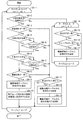
図7は、連動制御処理を示すフローチャートである。   FIG. 7 is a flowchart showing the interlock control process.

ステップS1におけるループ処理(ステップS2からステップS8までのループ処理)は、機器情報テーブル121に格納された全ての被制御機器20に対して行われる。例えば、機器情報テーブル121のNo.1の被制御機器20を、1番目の処理対象の被制御機器20として、ステップS1のループ処理が開始され、ステップS8の処理が終わると、機器情報テーブル121のNo.2の被制御機器20を、2番目の処理対象の被制御機器20としてステップS1のループ処理が行われる。機器情報テーブル121に格納された全ての被制御機器20に対してステップS1からステップS8までのループ処理が終わると、処理はステップS9に進む。本実施の形態では、ステップS1のループ処理は、機器情報テーブル121のNo.1からNo.12までの被制御機器20に対して行われる。   The loop processing in step S1 (loop processing from step S2 to step S8) is performed for all controlled devices 20 stored in the device information table 121. For example, the device information table 121 No. 1, the controlled device 20 is set as the first controlled device 20 to be processed, and the loop processing in step S1 is started. The loop process of step S1 is performed with the second controlled device 20 as the second controlled device 20 to be processed. When the loop processing from step S1 to step S8 is completed for all the controlled devices 20 stored in the device information table 121, the processing proceeds to step S9. In the present embodiment, the loop processing in step S1 is performed in accordance with No. in the device information table 121. 1 to No. This is performed for up to 12 controlled devices 20.

ステップS2では、機器制御装置10の情報取得部112は、通信部111を介して処理対象の被制御機器20(No.kの被制御機器20;例えば、第1のエアコン20A)から機器状態を取得する。   In step S2, the information acquisition unit 112 of the device control apparatus 10 changes the device state from the controlled device 20 to be processed (No. k controlled device 20; for example, the first air conditioner 20A) via the communication unit 111. get.

ステップS3では、情報取得部112は、通信部111を介して処理対象の被制御機器20から取得した機器状態情報と、機器情報テーブル121の機器状態情報121d(処理対象の被制御機器20の機器状態情報121d)に格納されている機器状態情報とを比較し、機器状態に変化があるかを判断する。   In step S3, the information acquisition unit 112 acquires the device state information acquired from the processing target controlled device 20 via the communication unit 111, and the device state information 121d of the device information table 121 (the device of the processing target controlled device 20). The device status information stored in the status information 121d) is compared to determine whether there is a change in the device status.

機器状態に変化がある場合(ステップS3:Yes)、処理はステップ4に進む。機器状態に変化がない場合(ステップS3:No)、処理はステップS7に進む。   If there is a change in the device state (step S3: Yes), the process proceeds to step 4. If there is no change in the device state (step S3: No), the process proceeds to step S7.

ステップ4では、情報取得部112は、機器情報テーブル121の機器状態情報121dに格納されている機器状態情報を更新する。   In step 4, the information acquisition unit 112 updates the device state information stored in the device state information 121 d of the device information table 121.

ステップS5では、制御部110(情報取得部112又は情報更新部114)は、機器状態が変化した回数のカウントを行う。例えば、制御部110は、被制御機器20が含まれるグループの変化回数を1加算する。さらに、他のグループに含まれる被制御機器20にいずれかの状態タグが付与されている場合は、制御部110は、他のグループと状態タグともとの被制御機器20が含まれるグループの組に対して、変化回数を1加算する。   In step S5, the control unit 110 (the information acquisition unit 112 or the information update unit 114) counts the number of times the device state has changed. For example, the control unit 110 adds 1 to the number of changes in the group including the controlled device 20. Furthermore, when any status tag is assigned to the controlled device 20 included in another group, the control unit 110 sets the group including the controlled device 20 with the other group and the status tag. 1 is added to the number of changes.

ステップS6では、情報更新部114は、処理対象の被制御機器20に、状態タグを付与するか判断する。ステップS6の処理の詳細は、図8を用いて説明する。   In step S <b> 6, the information update unit 114 determines whether to add a status tag to the controlled device 20 to be processed. Details of the processing in step S6 will be described with reference to FIG.

ステップS7では、情報更新部114は、機器情報テーブル121の状態タグ情報121f(処理対象の被制御機器20の状態タグ情報121f)に格納された状態タグ(例えば、“在室中(夜)”)が、処理対象の被制御機器20(例えば、第1のエアコン20A)に付与されてからの経過時間t1を算出する。経過時間t1が予め定められた時間t0(例えば、2時間)を越えている場合(ステップS7:Yes)、処理はステップS8に進む。   In step S7, the information update unit 114 stores the status tag (for example, “in the room (night)” stored in the status tag information 121f of the device information table 121 (the status tag information 121f of the controlled device 20 to be processed). ) Is calculated for the elapsed time t1 after being given to the controlled device 20 to be processed (for example, the first air conditioner 20A). When the elapsed time t1 exceeds a predetermined time t0 (for example, 2 hours) (step S7: Yes), the process proceeds to step S8.

経過時間t1が予め定められた時間t0を越えていない場合(ステップS7:No)、処理はステップS1に戻り、機器情報テーブル121に格納されている次の被制御機器20(例えば、第2のエアコン20B)を処理対象の被制御機器20として設定し、ステップS2以降の処理が行われる。機器情報テーブル121に格納されている全ての被制御機器20についてステップS1からステップS8までのループ処理が完了した場合、処理はステップS9に進む。   When the elapsed time t1 does not exceed the predetermined time t0 (step S7: No), the process returns to step S1, and the next controlled device 20 (for example, the second controlled device 20 stored in the device information table 121). The air conditioner 20B) is set as the controlled device 20 to be processed, and the processes after step S2 are performed. When the loop processing from step S1 to step S8 is completed for all controlled devices 20 stored in the device information table 121, the process proceeds to step S9.

ステップS8では、情報更新部114は、機器情報テーブル121の状態タグ情報121f(処理対象の被制御機器20の状態タグ情報121f)に格納されている状態タグ(例えば、“在室中(夜)”)を削除する。機器情報テーブル121に格納されている全ての被制御機器20についてステップS1からステップS8までのループ処理が完了した場合、処理はステップS9に進む。   In step S8, the information update unit 114 stores the status tag (for example, “in the room (night)” stored in the status tag information 121f of the device information table 121 (the status tag information 121f of the controlled device 20 to be processed). )) Is deleted. When the loop processing from step S1 to step S8 is completed for all controlled devices 20 stored in the device information table 121, the process proceeds to step S9.

ステップS9に示されるループ処理では、グループ情報テーブル122に格納されている全てのグループに対して行われる。具体的には、グループID情報122aに格納されたグループID“j”のグループを、第2のグループとして設定し、ステップS10からステップS14までのループ処理が行われる。例えば、グループ情報テーブル122のNo.1のグループID情報122aに格納されたグループID“1”を、1番目の処理対象のグループとして、ステップS9からステップS14までのループ処理が開始される。   The loop process shown in step S9 is performed for all the groups stored in the group information table 122. Specifically, the group with the group ID “j” stored in the group ID information 122a is set as the second group, and the loop processing from step S10 to step S14 is performed. For example, No. in the group information table 122 is displayed. The loop processing from step S9 to step S14 is started with the group ID “1” stored in the group ID information 122a of 1 as the first processing target group.

ステップ10では、情報更新部114は、処理対象のグループ(グループID=j;jは1以上の整数)についてのグループ別全日操作頻度Fall(j)を算出する。   In step 10, the information updating unit 114 calculates the group-wide all-day operation frequency Fall (j) for the group to be processed (group ID = j; j is an integer of 1 or more).

ステップS11に示されるループ処理では、グループ情報テーブル122に格納されている全てのグループに対して行われる。具体的には、グループID情報122aに格納されたグループID“i”(iは1以上の整数)のグループを、第1のグループとして設定し、ステップS12からステップS14までのループ処理が行われる。ただし、j=iの場合は、実行されない。すなわち、本実施の形態では、ステップS11に示されるループ処理は、(j,i)=(1,2),(1,3),(1,4),(2,1),(2,3),(2,4),(3,1),(3,2),(3,4),(4,1),(4,2),及び(4,3)の12組に対して行われる。   The loop process shown in step S11 is performed for all the groups stored in the group information table 122. Specifically, the group with the group ID “i” (i is an integer of 1 or more) stored in the group ID information 122a is set as the first group, and the loop processing from step S12 to step S14 is performed. . However, it is not executed when j = i. That is, in the present embodiment, the loop processing shown in step S11 is (j, i) = (1,2), (1,3), (1,4), (2,1), (2, 3), (2,4), (3,1), (3,2), (3,4), (4,1), (4,2), and (4,3) Done.

ステップS12では、情報更新部114は、グループ別状態タグ別操作頻度Ftag(i,tag,j)を算出する。   In step S12, the information updating unit 114 calculates the operation frequency Ftag (i, tag, j) for each status tag for each group.

ステップS13では、情報更新部114は、Ftag(i,tag,j)/Fall(j)によって算出された値F1が、閾値F0(例えば、10)以上であるか否かを判断する。   In step S13, the information updating unit 114 determines whether or not the value F1 calculated by Ftag (i, tag, j) / Fall (j) is greater than or equal to a threshold value F0 (for example, 10).

値F1が閾値以上である場合(ステップS13:Yes)、処理はステップS14に進む。値F1が閾値以上でない場合(ステップS13:No)、処理はステップS11に戻り、グループ情報テーブル122に格納されているグループID=2についてステップS12以降の処理が行われる。ステップ13の後、処理はステップS9に戻るか、ステップS11に戻るか、又はステップS15に進む。   If the value F1 is greater than or equal to the threshold (step S13: Yes), the process proceeds to step S14. If the value F1 is not greater than or equal to the threshold value (step S13: No), the process returns to step S11, and the processes after step S12 are performed for the group ID = 2 stored in the group information table 122. After step 13, the process returns to step S9, returns to step S11, or proceeds to step S15.

ステップS14では、情報更新部114は、グループ情報テーブル122の連動グループ情報122cに格納されている情報を更新する。具体的には、情報更新部114は、連動グループ情報122cの欄に格納される情報を、ステップS13の判定において条件を満たした、第1のグループの状態タグ(tag)及び第2のグループのグループID(j)の組からなる情報に更新する。連動グループ情報122cの欄には、複数の組が格納されてもよい。例えば、No.2の連動グループ情報122cの欄には組A及び組Bが格納されている。   In step S <b> 14, the information update unit 114 updates the information stored in the interlocking group information 122 c of the group information table 122. Specifically, the information updating unit 114 uses the information stored in the column of the interlocking group information 122c as the state tag (tag) of the first group and the second group that satisfy the condition in the determination in step S13. The information is updated to a group ID (j) pair. A plurality of sets may be stored in the column of the interlocking group information 122c. For example, no. The group A and the group B are stored in the column of the two linked group information 122c.

ステップS14の処理の後、処理は、ステップS11のループ処理に戻るか、ステップS9のループ処理に戻るか、又はステップS15に進む。   After the process of step S14, the process returns to the loop process of step S11, returns to the loop process of step S9, or proceeds to step S15.

ステップS15では、被制御機器20に対する機器制御処理を行う。ステップS15の処理の詳細は、図9を用いて説明する。   In step S15, device control processing for the controlled device 20 is performed. Details of the processing in step S15 will be described with reference to FIG.

ステップS15の処理が終わると、図7に示される連動制御の処理が終了する。   When the process of step S15 is completed, the interlock control process shown in FIG. 7 ends.

図8は、図7に示されるステップS6の処理(状態タグ付与判断処理)を示すフローチャートである。   FIG. 8 is a flowchart showing the process of step S6 shown in FIG. 7 (state tag assignment determination process).

ステップS6−1におけるループ処理(ステップS6−2からステップS6−17までの処理)は、状態タグ情報更新ルールテーブル124のNo.1からNo.m(mは1以上の整数)までの項目について繰り返される。本実施の形態では、状態タグ情報更新ルールテーブル124のNo.1からNo.18までの項目についてループ処理が繰り返される。   The loop process (the process from step S6-2 to step S6-17) in step S6-1 is performed as No. in the status tag information update rule table 124. 1 to No. It repeats about the item to m (m is an integer greater than or equal to 1). In the present embodiment, the No. of the status tag information update rule table 124 is changed. 1 to No. The loop process is repeated for up to 18 items.

ステップS6−2では、情報更新部114は、状態タグ情報更新ルールテーブル124のNo.mの対象機器状態124eに情報が格納されているか否かを判断する。言い換えると、情報更新部114は、No.mの対象機器状態124e及び対象状態タグ124fのいずれに情報が格納されているかを判断する。   In step S <b> 6-2, the information update unit 114 sets the No. in the status tag information update rule table 124. It is determined whether information is stored in m target device states 124e. In other words, the information update unit 114 is the No. It is determined in which of the m target device states 124e and the target state tag 124f the information is stored.

対象機器状態124eに情報が格納されている場合(ステップS6−2:Yes)、処理はステップS6−3に進む。対象機器状態124eに情報が格納されていない場合(ステップS6−2:No)、処理はステップS6−14に進む。   If information is stored in the target device state 124e (step S6-2: Yes), the process proceeds to step S6-3. When information is not stored in the target device state 124e (step S6-2: No), the process proceeds to step S6-14.

ステップS6−3では、情報更新部114は、No.kの被制御機器20(例えば、第1のエアコン20A)の機器種別(エアコン)が、状態タグ情報更新ルールテーブル124のNo.mの対象機器種別124bの欄に格納されている機器種別と一致するか判断する。一致する場合(ステップS6−3:Yes)、処理はステップS6−4に進む。一致しない場合(ステップS6−3:No)、処理はステップS6−11に進む。   In step S6-3, the information update unit 114 performs No. k, the device type (air conditioner) of the controlled device 20 (for example, the first air conditioner 20A) is set to No. It is determined whether or not it matches the device type stored in the column of m target device type 124b. If they match (step S6-3: Yes), the process proceeds to step S6-4. If they do not match (step S6-3: No), the process proceeds to step S6-11.

ステップS6−4では、情報更新部114は、状態タグ情報更新ルールテーブル124のNo.mの対象時刻124cの欄が空欄か否か判断する。対象時刻124cの欄が空欄である場合(ステップS6−4:Yes)、処理はステップS6−6に進む。対象時刻124cの欄が空欄でない場合(ステップS6−4:No)、処理はステップS6−5に進む。   In step S <b> 6-4, the information update unit 114 sets the No. It is determined whether or not the m target time 124c field is blank. If the target time 124c field is blank (step S6-4: Yes), the process proceeds to step S6-6. If the target time 124c field is not blank (step S6-4: No), the process proceeds to step S6-5.

ステップS6−5では、情報更新部114は、現在時刻(Time1)が、状態タグ情報更新ルールテーブル124のNo.mの対象時刻124cに格納された時刻(Time2)の範囲内であるか判断する。例えば、現在時刻が20時であり、かつNo.kの被制御機器20が第1の照明20Eであるとき、情報更新部114は、現在時刻(20時)が、対象機器種別124b“照明”の対象時刻124c“18時−6時”の範囲内であるか判断する。   In step S6-5, the information update unit 114 determines that the current time (Time1) is No. in the status tag information update rule table 124. It is determined whether it is within the range of the time (Time 2) stored in the target time 124c of m. For example, if the current time is 20:00 and no. When the k controlled device 20 is the first lighting 20E, the information updating unit 114 sets the current time (20:00) in the range of the target time 124c “18: 00-6 o'clock” of the target device type 124b “lighting”. It is judged whether it is in.

現在時刻が、対象時刻124cに格納された時刻の範囲内である場合(ステップS6−5:Yes)、処理はステップS6−6に進む。現在時刻が、No.mの対象時刻124cに格納された時刻の範囲内でない場合(ステップS6−5:No)、処理はステップS6−11に進む。   When the current time is within the time range stored in the target time 124c (step S6-5: Yes), the process proceeds to step S6-6. The current time is No. If it is not within the time range stored in the target time 124c of m (step S6-5: No), the process proceeds to step S6-11.

ステップS6−6では、情報更新部114は、状態タグ情報更新ルールテーブル124のNo.mの対象日付124dの欄が空欄か否か判断する。対象日付124dの欄が空欄である場合(ステップS6−6:Yes)、処理はステップ6−8に進む。対象日付124dの欄が空欄でない場合(ステップS6−6:No)、処理はステップS6−7に進む。   In step S <b> 6-6, the information update unit 114 sets the No. in the status tag information update rule table 124. It is determined whether or not the m target date 124d field is blank. If the target date 124d field is blank (step S6-6: Yes), the process proceeds to step 6-8. When the column of the target date 124d is not blank (step S6-6: No), the process proceeds to step S6-7.

ステップS6−7では、情報更新部114は、現在の日付(Date1)が、状態タグ情報更新ルールテーブル124のNo.mの対象日付124dに格納された日付(期間)(Date2)の範囲内であるか判断する。現在の日付が、対象日付124dに格納された日付の範囲内である場合(ステップS6−7:Yes)、処理はステップS6−8に進む。現在の日付が、対象日付124dに格納された日付の範囲内でない場合(ステップS6−7:No)、処理はステップS6−11に進む。   In step S6-7, the information update unit 114 indicates that the current date (Date1) is No. in the status tag information update rule table 124. It is determined whether it is within the range of the date (period) (Date2) stored in the target date 124d of m. When the current date is within the date range stored in the target date 124d (step S6-7: Yes), the process proceeds to step S6-8. If the current date is not within the date range stored in the target date 124d (step S6-7: No), the process proceeds to step S6-11.

ステップS6−8では、情報更新部114は、ステップS2で取得されたNo.kの被制御機器20の機器状態と、状態タグ情報更新ルールテーブル124のNo.mの対象機器状態124eに格納された機器状態とが一致するか判断する。一致する場合(ステップS6−8:Yes)、処理はステップS6−9に進む。一致しない場合(ステップS6−8:No)、処理はステップS6−11に進む。   In step S6-8, the information update unit 114 receives the No. acquired in step S2. k, the device status of the controlled device 20 and the No. in the status tag information update rule table 124. It is determined whether or not the device state stored in the m target device state 124e matches. If they match (step S6-8: Yes), the process proceeds to step S6-9. If they do not match (step S6-8: No), the process proceeds to step S6-11.

ステップS6−9では、情報更新部114は、機器情報テーブル121のNo.kの状態タグ情報121fの欄に、状態タグ情報更新ルールテーブル124のNo.mの付与状態タグ124aに格納されている状態タグを追加する。   In step S <b> 6-9, the information update unit 114 stores the No. in the device information table 121. In the column of the status tag information 121f of k, the No. of the status tag information update rule table 124 is displayed. The status tag stored in the assigned status tag 124a of m is added.

ステップS6−10では、情報更新部114は、ステップS6−9において状態タグを付与された被制御機器20と同じグループに属する他の被制御機器20の状態タグ情報121fの欄に、状態タグを追加する。   In step S6-10, the information updating unit 114 stores the status tag in the column of status tag information 121f of other controlled devices 20 belonging to the same group as the controlled device 20 to which the status tag is assigned in step S6-9. to add.

ステップS6−10の後は、ステップS6−1に戻り、状態タグ情報更新ルールテーブル124のNo.2についてステップS6−2以降の処理が再び繰り返される。本実施の形態では、状態タグ情報更新ルールテーブル124のNo.18までのループ処理が終わると、図8に示される処理(図7に示されるステップS6の処理)は終了する。   After step S6-10, the process returns to step S6-1, and No. in the status tag information update rule table 124 is returned. For step 2, the processing from step S6-2 onward is repeated again. In the present embodiment, the No. of the status tag information update rule table 124 is changed. When the loop process up to 18 is finished, the process shown in FIG. 8 (the process of step S6 shown in FIG. 7) is finished.

ステップS6−11では、情報更新部114は、状態タグ情報更新ルールテーブル124のNo.mの付与状態タグ124aに格納されている状態タグが既にNo.kの被制御機器20に付与されているか判断する。付与されている場合(ステップS6−11:Yes)、処理はステップS6−12に進む。付与されていない場合(ステップS6−11:No)、ステップS6−1のループ処理に戻るか又は図8に示される処理(図7に示されるステップS6の処理)を終了する。   In step S <b> 6-11, the information update unit 114 stores the No. in the status tag information update rule table 124. m, the status tag stored in the assigned status tag 124a is already No. It is determined whether or not it is given to k controlled devices 20. If it has been assigned (step S6-11: Yes), the process proceeds to step S6-12. If not given (step S6-11: No), the process returns to the loop process of step S6-1 or ends the process shown in FIG. 8 (process of step S6 shown in FIG. 7).

ステップS6−12では、情報更新部114は、機器情報テーブル121のNo.kの状態タグ情報121fの欄から、状態タグ情報更新ルールテーブル124のNo.mの付与状態タグ124aに格納されている状態タグと同じ状態タグを削除する。   In step S <b> 6-12, the information update unit 114 stores the No. in the device information table 121. k from the status tag information 121f column of the status tag information update rule table 124. The same status tag as the status tag stored in the assigned status tag 124a of m is deleted.

ステップS6−13では、情報更新部114は、No.kの被制御機器20と同じグループに属する被制御機器20の状態タグ情報121fの欄から、ステップ6−12で削除された状態タグと同じ状態タグを削除する。ステップS6−13の後は、ステップS6−1のループ処理に戻るか又は図8に示される処理(図7に示されるステップS6の処理)を終了する。   In step S6-13, the information updating unit 114 performs No. The same status tag as the status tag deleted in step 6-12 is deleted from the column of status tag information 121f of the controlled device 20 belonging to the same group as the controlled device 20 of k. After step S6-13, the process returns to the loop process of step S6-1 or ends the process shown in FIG. 8 (the process of step S6 shown in FIG. 7).

ステップS6−14におけるループ処理は、(ステップS6−15からステップS6−17までの処理)は、グループ情報テーブル122のNo.1からNo.n(nは1以上の整数)までの項目について繰り返される。本実施の形態では、グループ情報テーブル122のNo.1からNo.4までループ処理が繰り返される。   The loop processing in step S6-14 (processing from step S6-15 to step S6-17) is No. in the group information table 122. 1 to No. It repeats about the item to n (n is an integer greater than or equal to 1). In this embodiment, the No. of the group information table 122 is set. 1 to No. The loop process is repeated up to 4.

ステップS6−15では、情報更新部114は、状態タグ情報更新ルールテーブル124のNo.mの対象状態タグ124fに格納されている状態タグが、グループ情報テーブル122のNo.n(nは1以上の整数)の連動グループ情報122cに格納されている状態タグのいずれかと一致するか判断する。   In step S <b> 6-15, the information update unit 114 stores the No. in the status tag information update rule table 124. m, the status tag stored in the target status tag 124f of No. It is determined whether it matches any of the status tags stored in n (n is an integer of 1 or more) linked group information 122c.

一致する場合(ステップS6−15:Yes)、処理はステップS6−16に進む。一致しない場合(ステップS6−15:No)、処理はステップS6−14のループ処理に戻るか、ステップS6−1のループ処理に戻るか、又は図8に示される処理(図7に示されるステップS6の処理)を終了する。   If they match (step S6-15: Yes), the process proceeds to step S6-16. If they do not match (step S6-15: No), the process returns to the loop process of step S6-14, returns to the loop process of step S6-1, or the process shown in FIG. 8 (step shown in FIG. 7). The process of S6 is terminated.

ステップS6−16では、情報更新部114は、No.kの被制御機器20が属するグループ(例えば、第1のグループ)のグループID(No.kのグループID情報121e)が、グループ情報テーブル122のNo.nのグループID情報122aに格納されたグループID(例えば、第1のグループ)と一致するか判断する。   In step S6-16, the information updating unit 114 determines that No. The group ID (No. k group ID information 121e) of the group (for example, the first group) to which the controlled device 20 of k belongs is the No. k of the group information table 122. It is determined whether or not it matches the group ID (for example, the first group) stored in the n group ID information 122a.

一致する場合(ステップS6−16:Yes)、処理はステップS6−17に進む。一致しない場合(ステップS6−16:No)、処理はステップS6−14のループ処理に戻るか、ステップS6−1のループ処理に戻るか、又は図8に示される処理(図7に示されるステップS6の処理)を終了する。   If they match (step S6-16: Yes), the process proceeds to step S6-17. If they do not match (step S6-16: No), the process returns to the loop process of step S6-14, returns to the loop process of step S6-1, or the process shown in FIG. 8 (step shown in FIG. 7). The process of S6 is terminated.

ステップS6−17では、情報更新部114は、ステップS6−15で一致した状態タグと組となって連動グループ情報122cに格納されているグループIDによって示されるグループ(例えば、第2のグループ)と同じグループに属する全ての被制御機器20の状態タグ情報121fの欄に、状態タグ情報更新ルールテーブル124のNo.mの付与状態タグ124aに格納されている状態タグを追加する。これにより、例えば、通常、特定のグループに属する被制御機器20(具体的には、状態タグ情報121f)に付与される状態タグを、関連性の高い他のグループに属する被制御機器20(具体的には、状態タグ情報121f)に付与することができる。   In step S6-17, the information updating unit 114 sets a group (for example, the second group) indicated by the group ID stored in the interlocking group information 122c in combination with the state tag matched in step S6-15. In the column of status tag information 121f of all controlled devices 20 belonging to the same group, No. in the status tag information update rule table 124 is displayed. The status tag stored in the assigned status tag 124a of m is added. As a result, for example, the controlled device 20 (specifically, the status tag assigned to the controlled device 20 (specifically, the status tag information 121f) that normally belongs to a specific group is assigned to the controlled tag 20 (specifically, the status tag information 121f). Specifically, it can be given to the state tag information 121f).

ステップS6−17の後、ステップS6−14のループ処理に戻るか、ステップS6−1のループ処理に戻るか、又は図8に示される処理(図7に示されるステップS6の処理)を終了する。   After step S6-17, the process returns to the loop process of step S6-14, returns to the loop process of step S6-1, or ends the process shown in FIG. 8 (the process of step S6 shown in FIG. 7). .

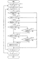
図9は、図7に示されるステップS15の処理(機器制御処理)を示すフローチャートである。   FIG. 9 is a flowchart showing the processing (device control processing) in step S15 shown in FIG.

ステップS15−1におけるループ処理(ステップS15−2からステップS15−10までのループ処理)は、機器情報テーブル121に格納された全ての被制御機器20に対して行われる。すなわち、ステップS15−1におけるループ処理は、機器情報テーブル121のNo.1からNo.p(pは1以上の整数)までの被制御機器20について繰り返される。本実施の形態では、機器情報テーブル121のNo.1からNo.12までの被制御機器20についてループ処理が繰り返される。   The loop processing in step S15-1 (loop processing from step S15-2 to step S15-10) is performed for all controlled devices 20 stored in the device information table 121. In other words, the loop processing in step S15-1 is performed as No. in the device information table 121. 1 to No. It repeats about the controlled apparatus 20 to p (p is an integer greater than or equal to 1). In the present embodiment, No. in the device information table 121 is displayed. 1 to No. The loop process is repeated for up to 12 controlled devices 20.

ステップS15−2におけるループ処理(ステップS15−3からステップS15−10までのループ処理)は、連動制御ルールテーブル123のNo.1からNo.q(qは1以上の整数)までの項目について繰り返される。本実施の形態では、連動制御ルールテーブル123のNo.1からNo.11までの項目についてループ処理が繰り返される。   The loop process in Step S15-2 (the loop process from Step S15-3 to Step S15-10) is performed in No. of the interlock control rule table 123. 1 to No. It repeats about the item to q (q is an integer greater than or equal to 1). In the present embodiment, the No. of the interlock control rule table 123 is set. 1 to No. The loop process is repeated for up to 11 items.

ステップS15−3では、制御内容選択部115は、連動制御ルールテーブル123のNo.1の有効無効情報123aに格納されている情報が“有効”であるか否かを判断する。“有効”である場合(ステップS15−3:Yes)、処理はステップS15−4に進む。“有効”でない場合、すなわち、無効である場合(ステップS15−3:No)、ステップS15−1のループ処理に戻るか、ステップS15−2のループ処理に戻るか、又は図9に示される処理(図7に示されるステップS15の処理)を終了する。   In step S <b> 15-3, the control content selection unit 115 sets the No. in the interlock control rule table 123. It is determined whether or not the information stored in the 1 valid / invalid information 123 a is “valid”. If it is “valid” (step S15-3: Yes), the process proceeds to step S15-4. When it is not “valid”, that is, when it is invalid (step S15-3: No), the process returns to the loop process of step S15-1, returns to the loop process of step S15-2, or the process shown in FIG. (Processing in step S15 shown in FIG. 7) is terminated.

ステップS15−4では、制御内容選択部115は、連動制御ルールテーブル123のNo.qの対象状態タグ123bに格納された状態タグが、No.pの被制御機器20に付与されている状態タグ(すなわち、No.pの状態タグ情報121fの状態タグ)のいずれかと一致するか判断する。一致する状態タグがある場合(ステップS15−4:Yes)、処理はステップS15−5に進む。一致する状態タグがない場合(ステップS15−4:No)、ステップS15−1のループ処理に戻るか、ステップS15−2のループ処理に戻るか、又は図9に示される処理(図7に示されるステップS15の処理)を終了する。   In step S <b> 15-4, the control content selection unit 115 sets the No. in the interlock control rule table 123. The status tag stored in the target status tag 123b of q is No. It is determined whether it matches any of the status tags assigned to the controlled device 20 of p (that is, the status tag of the status tag information 121f of No. p). If there is a matching status tag (step S15-4: Yes), the process proceeds to step S15-5. If there is no matching state tag (step S15-4: No), the process returns to the loop process of step S15-1, returns to the loop process of step S15-2, or the process shown in FIG. 9 (shown in FIG. 7). Step S15) to be completed.

ステップS15−5では、制御内容選択部115は、No.pの被制御機器20の機器種別121bと、連動制御ルールテーブル123のNo.qの対象機器種別123cに格納されている機器種別とが一致するかを判断する。一致する場合(ステップS15−5:Yes)、処理はステップS15−6に進む。一致しない場合(ステップS15−5:No)、ステップS15−1のループ処理に戻るか、ステップS15−2のループ処理に戻るか、又は図9に示される処理(図7に示されるステップS15の処理)を終了する。   In step S15-5, the control content selection unit 115 performs No. p, the device type 121b of the controlled device 20 and the No. of the interlock control rule table 123. It is determined whether or not the device type stored in the target device type 123c of q matches the device type. If they match (step S15-5: Yes), the process proceeds to step S15-6. If they do not match (step S15-5: No), the process returns to the loop process of step S15-1, the process returns to the loop process of step S15-2, or the process shown in FIG. 9 (in step S15 shown in FIG. 7). Process).

ステップS15−6では、制御内容選択部115は、連動制御ルールテーブル123のNo.qの対象時刻123dの欄が空欄かどうかを判断する。空欄である場合(ステップS15−6:Yes)、処理はステップ15−8に進む。空欄でない場合(ステップS15−6:No)、処理はステップS15−7に進む。   In step S15-6, the control content selection unit 115 sets the No. in the interlock control rule table 123. It is determined whether or not the column of the target time 123d of q is blank. If it is blank (step S15-6: Yes), the process proceeds to step 15-8. If it is not blank (step S15-6: No), the process proceeds to step S15-7.

ステップS15−7では、制御内容選択部115は、現在時刻(Time1)が、連動制御ルールテーブル123のNo.qの対象時刻123dに格納された時刻(Time3)の範囲内であるか判断する。対象時刻123dに格納された時刻の範囲内である場合(ステップS15−7:Yes)、処理はステップS15−8に進む。対象時刻123dに格納された時刻の範囲内でない場合(ステップS15−7:No)、ステップS15−1のループ処理に戻るか、ステップS15−2のループ処理に戻るか、又は図9に示される処理(図7に示されるステップS15の処理)を終了する。   In step S15-7, the control content selection unit 115 indicates that the current time (Time1) is No. in the interlock control rule table 123. It is determined whether it is within the range of the time (Time 3) stored in the target time 123d of q. When it is within the time range stored in the target time 123d (step S15-7: Yes), the process proceeds to step S15-8. When it is not within the time range stored in the target time 123d (step S15-7: No), the process returns to the loop process of step S15-1, returns to the loop process of step S15-2, or is shown in FIG. The process (the process of step S15 shown in FIG. 7) is terminated.

ステップS15−8では、制御内容選択部115は、連動制御ルールテーブル123のNo.qの対象日付123eの欄が空欄かどうか判断する。空欄である場合(ステップS15−8:Yes)、処理はステップ15−10に進む。空欄でない場合(ステップS15−8:No)、処理はステップS15−9に進む。   In step S15-8, the control content selection unit 115 sets No. in the interlocking control rule table 123. It is determined whether or not the column of q target date 123e is blank. If it is blank (step S15-8: Yes), the process proceeds to step 15-10. If it is not blank (step S15-8: No), the process proceeds to step S15-9.

ステップS15−9では、制御内容選択部115は、現在の日付(Date1)が、連動制御ルールテーブル123のNo.qの対象日付123eに格納された日付(期間)(Date3)の範囲内であるか判断する。対象日付123eに格納された日付の範囲内である場合(ステップS15−9:Yes)、処理はステップS15−10に進む。対象日付123eに格納された日付の範囲内でない場合(ステップS15−9:No)、ステップS15−1のループ処理に戻るか、ステップS15−2のループ処理に戻るか、又は図9に示される処理(図7に示されるステップS15の処理)を終了する。   In step S15-9, the control content selection unit 115 indicates that the current date (Date1) is No. in the interlock control rule table 123. It is determined whether it is within the range of the date (period) (Date 3) stored in the target date 123e of q. If it is within the range of the date stored in the target date 123e (step S15-9: Yes), the process proceeds to step S15-10. When it is not within the range of the date stored in the target date 123e (step S15-9: No), the process returns to the loop process of step S15-1, returns to the loop process of step S15-2, or is shown in FIG. The process (the process of step S15 shown in FIG. 7) is terminated.

ステップS15−10では、制御内容選択部115は、連動制御ルールテーブル123のNo.qの制御内容123fの欄に格納されている機器制御命令及び機器制御命令の送信先の少なくとも1つの被制御機器20を選択し、命令送信部116に送信する。命令送信部116は、制御内容選択部115から受信した機器制御命令を、通信部111を介してNo.qの被制御機器20(制御内容選択部115によって選択された少なくとも1つの被制御機器20)に送信する。制御内容123fの欄に複数の機器制御命令が格納されている場合、1つずつ順番に機器制御命令が送信される。例えば、No.1(q=1)の場合、機器制御命令“電源:入”がNo.1の被制御機器20(例えば、浴室換気乾燥機20J)に送信され、続いて、機器制御命令“運転モード:送風”がNo.1の被制御機器20に送信される。   In step S15-10, the control content selection unit 115 sets No. in the interlock control rule table 123. The device control command stored in the column of the control content 123 f of q and at least one controlled device 20 that is the transmission destination of the device control command are selected and transmitted to the command transmission unit 116. The command transmission unit 116 sends the device control command received from the control content selection unit 115 to No. 1 via the communication unit 111. q to the controlled device 20 (at least one controlled device 20 selected by the control content selection unit 115). When a plurality of device control commands are stored in the control content field 123f, the device control commands are transmitted one by one in order. For example, no. 1 (q = 1), the device control command “Power: On” is No. 1 to the controlled device 20 (for example, bathroom ventilation dryer 20J). 1 to the controlled device 20.

ステップS15−10の後、ステップS15−1のループ処理に戻るか、ステップS15−2のループ処理に戻るか、又は図9に示される処理(図7に示されるステップS15の処理)を終了する。   After step S15-10, the process returns to the loop process of step S15-1, returns to the loop process of step S15-2, or ends the process shown in FIG. 9 (the process of step S15 shown in FIG. 7). .

実施の形態に係る機器制御装置10、及び機器制御装置10を含む機器制御システム1、及び機器制御システム1における機器制御方法により得られる効果について説明する。   The effects obtained by the device control device 10 according to the embodiment, the device control system 1 including the device control device 10, and the device control method in the device control system 1 will be described.

機器制御装置10の制御部110は、制御ルール情報に基づいて機器制御命令の送信先の少なくとも1つの被制御機器20を、複数の被制御機器20の中から選択し、選択された1又は複数の被制御機器20に制御命令を送信するので、ユーザの利便性の高い機器制御装置10、機器制御システム1、及び機器制御システム1における機器制御方法を提供することができる。   Based on the control rule information, the control unit 110 of the device control apparatus 10 selects at least one controlled device 20 that is a transmission destination of the device control command from the plurality of controlled devices 20, and selects one or more selected devices. Since the control command is transmitted to the controlled device 20, the device control apparatus 10, the device control system 1, and the device control method in the device control system 1 that are highly convenient for the user can be provided.

例えば、連動制御の基準となる基準機器及び、基準機器の動作(状態)と連動するように制御される制御対象機器が、いずれも固定されないので、任意の被制御機器20に対して遠隔制御を行うことができる。   For example, since the reference device that is the reference for the interlock control and the control target device that is controlled so as to be interlocked with the operation (state) of the reference device are not fixed, remote control can be performed on any controlled device 20. It can be carried out.

さらに、複数の被制御機器20の各々が、互いに異なる部屋に設置された場合であっても、任意の被制御機器20の状態(状態タグの付与状況又は機器状態)に応じて、他の部屋に設置された被制御機器20の遠隔制御を行うことができる。   Furthermore, even if each of the plurality of controlled devices 20 is installed in different rooms, another room may be used depending on the state of the arbitrary controlled device 20 (status tag assignment status or device status). It is possible to remotely control the controlled device 20 installed in the network.

実施の形態では、情報更新部114が、被制御機器20に対して状態タグを付与し、状態タグに基づいて制御内容選択部115が被制御機器20の制御内容を決定する。ここで、状態タグを付与する際に、情報更新部114は、機器状態だけでなく、グループ情報テーブル122、特に連動グループ情報122cを参照し、状態タグの付与条件の判断を行う。これにより、ある被制御機器20(例えば、第1のグループの被制御機器20)の状態が変化した際に、他のグループに属する被制御機器20(例えば、第2のグループの被制御機器20)を制御することが可能となる。   In the embodiment, the information update unit 114 gives a status tag to the controlled device 20, and the control content selection unit 115 determines the control content of the controlled device 20 based on the status tag. Here, when assigning the status tag, the information updating unit 114 refers to not only the device status but also the group information table 122, particularly the interlocking group information 122c, and determines the status tag granting condition. Thereby, when the state of a certain controlled device 20 (for example, the controlled device 20 in the first group) changes, the controlled device 20 (for example, the controlled device 20 in the second group) belonging to another group. ) Can be controlled.

また、連動制御において参照される連動グループ情報122cは、グループの関連性の高さを示す。具体的には、連動制御において参照される連動グループ情報122cは、あるグループの被制御機器20(例えば、第1のグループの被制御機器20)に特定の状態タグが付与されている状態において、使用される頻度の高い被制御機器20を含むグループ(例えば、第2のグループ)を表す。これにより、実際に使用されているグループの被制御機器20(例えば、第2のグループの被制御機器20)を連動制御の対象として選択することができ、関連性の低い被制御機器20(例えば、第3のグループの被制御機器20)に対して遠隔制御が行われることを防止できる。   Further, the interlocking group information 122c referred to in the interlocking control indicates the degree of group relevance. Specifically, the interlocking group information 122c referred to in the interlocking control is in a state where a specific status tag is assigned to the controlled device 20 of a certain group (for example, the controlled device 20 of the first group). The group (for example, 2nd group) containing the controlled apparatus 20 with high frequency of use is represented. As a result, the controlled device 20 of the group that is actually used (for example, the controlled device 20 of the second group) can be selected as the target of the interlock control, and the controlled device 20 (for example, less relevant) Remote control of the third group of controlled devices 20) can be prevented.

さらに、ある被制御機器20(例えば、第1のグループの被制御機器20)にいずれかの状態タグが付与された場合に、その被制御機器20(例えば、第1のグループの被制御機器20)と同じグループに属する他の被制御機器20にも同じ状態タグが付与される。これにより、使用されているグループの全ての被制御機器20に状態タグが付与され、連動制御の判断の対象とすることができるので、連動制御の対象から外れることを防止することができる。   Further, when any status tag is given to a certain controlled device 20 (for example, the controlled device 20 in the first group), the controlled device 20 (for example, the controlled device 20 in the first group). The same status tag is also assigned to other controlled devices 20 belonging to the same group. Thereby, since the status tag is given to all the controlled devices 20 of the group being used and can be set as the target of the interlock control, it can be prevented from being excluded from the target of the interlock control.

また、状態タグが付与されて一定時間経つなど、状態タグが削除される条件を満たした場合に、状態タグを削除する代わりに、他の状態タグに変更させることもできる。これにより、あるグループの被制御機器20の使用が終わった後に、異なるグループの被制御機器20を制御するなど、異なる制御タイミング(機器制御命令の異なる送信タイミング)による連動制御が可能となる。   In addition, when a condition for deleting the state tag is satisfied, such as when a certain period of time has passed since the state tag is given, the state tag can be changed to another state tag instead of being deleted. As a result, after the use of the controlled device 20 of a certain group is finished, interlocking control at different control timings (different transmission timings of device control commands) such as controlling the controlled devices 20 of different groups becomes possible.

また、被制御機器20を連動制御させるための判断条件は、状態タグに基づいて設定される。状態タグに、例えば、“入浴後”など、ユーザにとって認識しやすい文字列を対応させることで、ユーザが判断条件の有効無効の設定をする場合でも、被制御機器20の詳細な状態又は複雑な判断条件を意識することなく設定ができる。   In addition, a determination condition for interlocking control of the controlled device 20 is set based on the state tag. For example, even if the user sets valid / invalid of the determination condition by associating the status tag with a character string that is easy for the user to recognize, such as “after bathing”, the detailed state of the controlled device 20 or a complicated state Settings can be made without being aware of judgment conditions.

変形例.
図10は、変形例に係る機器制御装置における制御部110aの構成を示すブロック図である。制御部110aは、実施の形態1に係る機器制御装置10における制御部110に適用可能である。
Modified example.
FIG. 10 is a block diagram illustrating a configuration of the control unit 110a in the device control apparatus according to the modification. The control unit 110a can be applied to the control unit 110 in the device control apparatus 10 according to the first embodiment.

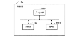
制御部110aは、CPU(Central Processing Unit)等のプロセッサ110b、ROM(Read Only Memory)110c、及びRAM(Random Access Memory)110dを有する。ROM110cには機器制御装置内の構成要素を制御するためのプログラム等が格納されている。RAM110dは、ROM110cに格納されたプログラム等をロードする記憶領域として用いられる。プロセッサ110bは、例えば、RAM110dにプログラムをロードしてプログラムを実行することにより、制御部110aの機能を実現する。例えば、実施の形態1で説明した情報取得部112、情報更新部114、命令送信部116、及び制御内容選択部115の各々の機能は、プロセッサ110bがROM110cに格納されたプログラムを実行することにより、実現される。   The control unit 110a includes a processor 110b such as a CPU (Central Processing Unit), a ROM (Read Only Memory) 110c, and a RAM (Random Access Memory) 110d. The ROM 110c stores a program for controlling the components in the device control apparatus. The RAM 110d is used as a storage area for loading a program or the like stored in the ROM 110c. The processor 110b implements the function of the control unit 110a by, for example, loading a program into the RAM 110d and executing the program. For example, the functions of the information acquisition unit 112, the information update unit 114, the command transmission unit 116, and the control content selection unit 115 described in the first embodiment are executed by the processor 110b executing a program stored in the ROM 110c. Realized.

1 機器制御システム、 10 機器制御装置、 20 被制御機器、 110,110a 制御部、 111 通信部、 112 情報取得部、 113 記憶部、 114 情報更新部、 115 制御内容選択部、 116 命令送信部、 117 操作表示部、 117a 表示部、 117b 操作部。   DESCRIPTION OF SYMBOLS 1 apparatus control system, 10 apparatus control apparatus, 20 controlled apparatus, 110,110a control part, 111 communication part, 112 information acquisition part, 113 memory | storage part, 114 information update part, 115 control content selection part, 116 command transmission part, 117 operation display part, 117a display part, 117b operation part.

Claims (12)

複数の被制御機器を遠隔制御する機器制御装置であって、
前記複数の被制御機器と通信する通信部と、
前記通信部を介して、前記複数の被制御機器のうちの少なくともいずれかを制御する制御命令を送信する制御部と、
情報が格納される記憶部と
を備え、
前記記憶部は、前記制御命令と、前記制御命令の送信の可否を決定する制御ルール情報とを格納し、
前記制御部は、前記制御命令の送信先の少なくとも1つの被制御機器を、前記制御ルール情報に基づいて前記複数の被制御機器の中から選択し、前記選択された被制御機器に前記制御命令を送信する
ことを特徴とする機器制御装置。
A device control device for remotely controlling a plurality of controlled devices,
A communication unit that communicates with the plurality of controlled devices;
A control unit that transmits a control command for controlling at least one of the plurality of controlled devices via the communication unit;
A storage unit for storing information,
The storage unit stores the control command and control rule information that determines whether the control command can be transmitted,
The control unit selects at least one controlled device to which the control command is transmitted from the plurality of controlled devices based on the control rule information, and sends the control command to the selected controlled device. A device control apparatus characterized by transmitting
前記制御ルール情報は、前記複数の被制御機器のうちの少なくとも1つの被制御機器と関連付けられる情報であるタグを含み、
前記制御部は、前記複数の被制御機器のうちの少なくとも1つの被制御機器と前記タグとを関連付けた状態で前記タグを前記記憶部に格納し、
前記制御部は、前記タグが関連付けられた被制御機器に前記制御命令を送信する
ことを特徴とする請求項1に記載の機器制御装置。
The control rule information includes a tag that is information associated with at least one controlled device among the plurality of controlled devices,
The control unit stores the tag in the storage unit in a state in which at least one controlled device of the plurality of controlled devices is associated with the tag,
The device control apparatus according to claim 1, wherein the control unit transmits the control command to a controlled device associated with the tag.
前記タグが前記複数の被制御機器のうちの第1の被制御機器に関連付けられている状態において、前記制御部は、前記第1の被制御機器と前記複数の被制御機器のうちの第2の被制御機器とが互いに関連性が高いと判断した場合、前記制御部は、前記第1の被制御機器及び前記第2の被制御機器と、前記タグとを関連付けた状態で前記タグを前記記憶部に格納することを特徴とする請求項2に記載の機器制御装置。   In a state in which the tag is associated with a first controlled device among the plurality of controlled devices, the control unit is configured to output the first controlled device and the second controlled device among the plurality of controlled devices. The controlled device determines that the tag is associated with the tag in a state in which the first controlled device and the second controlled device are associated with each other. The apparatus control apparatus according to claim 2, wherein the apparatus control apparatus is stored in a storage unit. 前記複数の被制御機器の各々は、複数のグループのいずれかに分類されており、前記複数のグループのうちの1つのグループに分類された、前記複数の被制御機器のうちの少なくとも1つの被制御機器と、前記タグとが関連付けられた状態で前記タグが前記記憶部に格納されていることを特徴とする請求項2又は3に記載の機器制御装置。   Each of the plurality of controlled devices is classified into one of a plurality of groups, and at least one controlled device of the plurality of controlled devices classified into one group of the plurality of groups. The device control apparatus according to claim 2 or 3, wherein the tag is stored in the storage unit in a state where the control device and the tag are associated with each other. 前記複数のグループのうちの前記1つのグループに分類された前記1つの被制御機器に前記タグが関連付けられた状態で前記タグが前記記憶部に格納された場合、前記制御部は、前記タグと、前記複数のグループのうちの前記1つのグループに分類された全ての被制御機器とを関連付けた状態で前記タグを前記記憶部に格納することを特徴とする請求項4に記載の機器制御装置。   When the tag is stored in the storage unit in a state in which the tag is associated with the one controlled device classified into the one group of the plurality of groups, the control unit includes the tag and 5. The device control apparatus according to claim 4, wherein the tag is stored in the storage unit in a state in which all the controlled devices classified into the one group of the plurality of groups are associated with each other. . 前記複数の被制御機器の各々は、複数のグループのうちのいずれのグループに分類されているかを示すグループ情報によって、前記複数のグループのうちのいずれかに分類され、前記グループ情報が前記記憶部に格納されていることを特徴とする請求項4又は5に記載の機器制御装置。   Each of the plurality of controlled devices is classified into one of the plurality of groups according to group information indicating which group of the plurality of groups is classified, and the group information is stored in the storage unit The device control device according to claim 4, wherein the device control device is stored in the device control device. 前記複数の被制御機器のうちの少なくとも1つの被制御機器と前記タグとが予め関連付けられた状態で前記タグが前記記憶部に格納されていることを特徴とする請求項2から6のいずれか1項に記載の機器制御装置。   The tag is stored in the storage unit in a state where at least one controlled device of the plurality of controlled devices and the tag are associated in advance. The apparatus control apparatus according to item 1. 前記制御部は、予め定められた時間が経過したときに、前記タグの情報を変更することを特徴とする請求項2から7のいずれか1項に記載の機器制御装置。   The device control apparatus according to claim 2, wherein the control unit changes the information of the tag when a predetermined time has elapsed. 前記複数の被制御機器のうちの少なくとも2つの被制御機器が、互いに異なる部屋に設置されており、
前記制御部は、前記制御命令の送信先の被制御機器として前記少なくとも2つの被制御機器を選択し、前記選択された前記少なくとも2つの被制御機器に前記制御命令を送信する
ことを特徴とする請求項1から8のいずれか1項に記載の機器制御装置。
At least two controlled devices of the plurality of controlled devices are installed in different rooms;
The control unit selects the at least two controlled devices as controlled devices to which the control command is transmitted, and transmits the control command to the selected at least two controlled devices. The apparatus control apparatus of any one of Claim 1 to 8.
前記制御ルール情報を表示する操作表示部をさらに有し、前記操作表示部から前記制御ルール情報が入力されることを特徴とする請求項1から9のいずれか1項に記載の機器制御装置。   The apparatus control apparatus according to claim 1, further comprising an operation display unit that displays the control rule information, wherein the control rule information is input from the operation display unit. 複数の被制御機器と、
前記複数の被制御機器を遠隔制御する機器制御装置と
を備え、
前記機器制御装置は、
前記複数の被制御機器と通信する通信部と、
前記通信部を介して、前記複数の被制御機器のうちの少なくともいずれかを制御する制御命令を送信する制御部と、
情報が格納される記憶部と
を有し、
前記記憶部は、前記制御命令と、前記制御命令の送信の可否を決定する制御ルール情報とを格納し、
前記制御部は、前記制御命令の送信先の少なくとも1つの被制御機器を、前記制御ルール情報に基づいて前記複数の被制御機器の中から選択し、前記選択された被制御機器に前記制御命令を送信する
ことを特徴とする機器制御システム。
Multiple controlled devices;
A device control device for remotely controlling the plurality of controlled devices,
The device control device
A communication unit that communicates with the plurality of controlled devices;
A control unit that transmits a control command for controlling at least one of the plurality of controlled devices via the communication unit;
A storage unit for storing information,
The storage unit stores the control command and control rule information that determines whether the control command can be transmitted,
The control unit selects at least one controlled device to which the control command is transmitted from the plurality of controlled devices based on the control rule information, and sends the control command to the selected controlled device. A device control system characterized by transmitting
複数の被制御機器と、前記複数の被制御機器のうちの少なくともいずれかを制御する制御命令及び前記制御命令の送信の可否を決定する制御ルール情報が格納された機器制御装置とを備えるシステムにおける機器制御方法であって、
前記制御命令の送信先の少なくとも1つの被制御機器を、前記制御ルール情報に基づいて前記複数の被制御機器の中から選択するステップと、
前記選択された被制御機器に前記制御命令を送信するステップと
を備える
ことを特徴とする機器制御方法。
A system comprising: a plurality of controlled devices; and a device control device storing a control command for controlling at least one of the plurality of controlled devices and control rule information for determining whether the control command can be transmitted. A device control method,
Selecting at least one controlled device as a transmission destination of the control command from the plurality of controlled devices based on the control rule information;
Transmitting the control command to the selected controlled device. A device control method comprising:
JP2016039224A 2016-03-01 2016-03-01 Apparatus control device, apparatus control system, and apparatus control method Pending JP2017158024A (en)

Priority Applications (1)

Application Number Priority Date Filing Date Title
JP2016039224A JP2017158024A (en) 2016-03-01 2016-03-01 Apparatus control device, apparatus control system, and apparatus control method

Applications Claiming Priority (1)

Application Number Priority Date Filing Date Title
JP2016039224A JP2017158024A (en) 2016-03-01 2016-03-01 Apparatus control device, apparatus control system, and apparatus control method

Publications (2)

Publication Number Publication Date
JP2017158024A true JP2017158024A (en) 2017-09-07
JP2017158024A5 JP2017158024A5 (en) 2017-12-14

Family

ID=59810492

Family Applications (1)

Application Number Title Priority Date Filing Date
JP2016039224A Pending JP2017158024A (en) 2016-03-01 2016-03-01 Apparatus control device, apparatus control system, and apparatus control method

Country Status (1)

Country Link
JP (1) JP2017158024A (en)

Cited By (3)

* Cited by examiner, † Cited by third party
Publication number Priority date Publication date Assignee Title
JP2020005011A (en) * 2018-06-25 2020-01-09 アイホン株式会社 Nurse call system
CN113655705A (en) * 2021-07-21 2021-11-16 上海外高桥造船有限公司 Safety device and configuration method and configuration system thereof
JP2023002098A (en) * 2021-06-22 2023-01-10 ダイキン工業株式会社 Interlock control method, program, device and system

Citations (4)

* Cited by examiner, † Cited by third party
Publication number Priority date Publication date Assignee Title
JP2005102156A (en) * 2003-08-21 2005-04-14 Matsushita Electric Ind Co Ltd Interlocking system, interlocking control device and its method
JP2008249233A (en) * 2007-03-30 2008-10-16 Mitsubishi Electric Corp Air conditioning system
WO2011099075A1 (en) * 2010-02-12 2011-08-18 三菱電機株式会社 Air conditioning system management device
JP2014230285A (en) * 2014-06-05 2014-12-08 三菱電機株式会社 Control system, terminal device, controller, control method and program

Patent Citations (5)

* Cited by examiner, † Cited by third party
Publication number Priority date Publication date Assignee Title
JP2005102156A (en) * 2003-08-21 2005-04-14 Matsushita Electric Ind Co Ltd Interlocking system, interlocking control device and its method
JP2008249233A (en) * 2007-03-30 2008-10-16 Mitsubishi Electric Corp Air conditioning system
WO2011099075A1 (en) * 2010-02-12 2011-08-18 三菱電機株式会社 Air conditioning system management device
US20120296478A1 (en) * 2010-02-12 2012-11-22 Mitsubishi Electric Corporation Control system of air conditioning system
JP2014230285A (en) * 2014-06-05 2014-12-08 三菱電機株式会社 Control system, terminal device, controller, control method and program

Cited By (4)

* Cited by examiner, † Cited by third party
Publication number Priority date Publication date Assignee Title
JP2020005011A (en) * 2018-06-25 2020-01-09 アイホン株式会社 Nurse call system
JP7057724B2 (en) 2018-06-25 2022-04-20 アイホン株式会社 Nurse call system
JP2023002098A (en) * 2021-06-22 2023-01-10 ダイキン工業株式会社 Interlock control method, program, device and system
CN113655705A (en) * 2021-07-21 2021-11-16 上海外高桥造船有限公司 Safety device and configuration method and configuration system thereof

Similar Documents

Publication Publication Date Title
CN108573596B (en) Control method
JP6194693B2 (en) COMMUNICATION DEVICE, CONTROL SYSTEM, COMMUNICATION PROGRAM, AND COMMUNICATION METHOD
JP6301829B2 (en) Control method
US10135631B2 (en) Electric equipment management apparatus, electric equipment management method, and electric equipment management system
JP6140214B2 (en) CONTROL DEVICE, CONTROL DEVICE CONTROL METHOD, CONTROL SYSTEM, ENVIRONMENT CONTROL DEVICE, AND CONTROL PROGRAM
US20150033136A1 (en) Method for controlling information apparatus and computer-readable recording medium
US20160080465A1 (en) Control method of information device, and non-transitory computer-readable recording medium storing program
US9565287B2 (en) Remote control method and remote control system
WO2014103307A1 (en) Control method
JP2017158024A (en) Apparatus control device, apparatus control system, and apparatus control method
US20210167984A1 (en) Method for controlling an air conditioner, communication control method, and communication system
JP2015064154A (en) Air conditioning management device
WO2014185174A1 (en) Energy management controller, energy management system, energy management method, and program
US11435107B2 (en) Air conditioning system
JP2019015428A (en) Air conditioning system and server
JP2011205413A (en) Apparatus control system
JP7175211B2 (en) Information processing system
EP3209026B1 (en) Control processing method, electric device, and control processing program
JP2018026814A (en) Apparatus control system, apparatus control method, and control program
JP2017138098A (en) Air-conditioning management device
JP2012175377A (en) Appliance control device and appliance control method
WO2019186993A1 (en) Terminal apparatus, device control system, device control method, and program
KR102479578B1 (en) Electronic apparatus and control method thereof
WO2017119025A1 (en) Information terminal, control device, control method, and recording medium
JP6398275B2 (en) Device control apparatus, device control method, and device control system

Legal Events

Date Code Title Description
A521 Request for written amendment filed

Free format text: JAPANESE INTERMEDIATE CODE: A523

Effective date: 20171106

A621 Written request for application examination

Free format text: JAPANESE INTERMEDIATE CODE: A621

Effective date: 20171106

A977 Report on retrieval

Free format text: JAPANESE INTERMEDIATE CODE: A971007

Effective date: 20180914

A131 Notification of reasons for refusal

Free format text: JAPANESE INTERMEDIATE CODE: A131

Effective date: 20181016

A02 Decision of refusal

Free format text: JAPANESE INTERMEDIATE CODE: A02

Effective date: 20190409