JP2017156874A - Automatic driving system - Google Patents

Automatic driving system Download PDF

Info

Publication number
JP2017156874A
JP2017156874A JP2016037873A JP2016037873A JP2017156874A JP 2017156874 A JP2017156874 A JP 2017156874A JP 2016037873 A JP2016037873 A JP 2016037873A JP 2016037873 A JP2016037873 A JP 2016037873A JP 2017156874 A JP2017156874 A JP 2017156874A
Authority
JP
Japan
Prior art keywords
candidate
vehicle
course
route
unit
Prior art date
Legal status (The legal status is an assumption and is not a legal conclusion. Google has not performed a legal analysis and makes no representation as to the accuracy of the status listed.)
Pending
Application number
JP2016037873A
Other languages
Japanese (ja)
Inventor
市川 健太郎
Kentaro Ichikawa
健太郎 市川
佐藤 国仁
Kunihito Sato
国仁 佐藤
博充 浦野
Hiromitsu Urano
博充 浦野
泰亮 菅岩
Taisuke Sugaiwa
泰亮 菅岩
浩之 船谷
Hiroyuki Funatani
浩之 船谷
文洋 奥村
Fumihiro Okumura
文洋 奥村
麻衣子 平野
Maiko Hirano
麻衣子 平野
Current Assignee (The listed assignees may be inaccurate. Google has not performed a legal analysis and makes no representation or warranty as to the accuracy of the list.)
Toyota Motor Corp
Original Assignee
Toyota Motor Corp
Priority date (The priority date is an assumption and is not a legal conclusion. Google has not performed a legal analysis and makes no representation as to the accuracy of the date listed.)
Filing date
Publication date
Application filed by Toyota Motor Corp filed Critical Toyota Motor Corp
Priority to JP2016037873A priority Critical patent/JP2017156874A/en
Publication of JP2017156874A publication Critical patent/JP2017156874A/en
Pending legal-status Critical Current

Links

Images

Landscapes

  • Instructional Devices (AREA)
  • Navigation (AREA)
  • Traffic Control Systems (AREA)

Abstract

PROBLEM TO BE SOLVED: To provide an automatic driving system with high convenience when a destination is not set in advance.SOLUTION: An automatic driving system 1 comprises: a direction indicator 6; an HMI 8; a map database 5; a vehicle location recognition part 12; a candidate calculation part 141 that calculates a plurality of course candidates on the basis of map information and the location of a vehicle; a candidate evaluation part 142 that weights the plurality of course candidates on the basis of weights set in advance, and evaluates the plurality of course candidates; a candidate selection part 143 that narrows down the plurality of candidates on the basis of evaluation results made by the candidate evaluation part 142, causes the HMI 8 to display the narrowed course candidates, and recognizes the course candidates selected by an occupant from among the course candidates displayed on the HMI 8 on the basis of received results made by the direction indicator 6; and a travel plan generation part 15 that generates a travel plan of the vehicle including a control target value according to a location on a target course which is a course candidate recognized by the candidate selection part 143.SELECTED DRAWING: Figure 1

Description

本発明は、自動運転システムに関する。   The present invention relates to an automatic driving system.

従来、進行方向の地形情報を取得し、取得した地形情報に基づいて局所地図を作成し、作成した局所地図に基づいて道情報を認識し、認識した道情報に基づいて走行経路を生成する無人移動体が知られている(例えば特許文献1)。この無人移動体では、道路や交差点に関する事前情報が一切得られない状況下における曲がり道及び交差点での走行の円滑化が図られている。   Conventionally, unattended who obtains terrain information in the traveling direction, creates a local map based on the obtained terrain information, recognizes road information based on the created local map, and generates a driving route based on the recognized road information A moving body is known (for example, Patent Document 1). In this unmanned moving body, smooth traveling on a curved road and an intersection under a situation where no prior information on a road or an intersection is obtained is achieved.

特開2012−159954号公報JP 2012-159954 A

車両の自動運転システムにおいては、例えば乗員により目的地が予め設定されていない場合、利便性の観点から、複数の進路候補が表示部に表示され、表示された進路候補のうち乗員により選択された進路候補が目標進路とすることが考えられる。しかしながら、表示部に表示される進路候補の数が多いと、乗員が進路候補を選択することが煩雑となり、自動運転システムの利便性が損なわれるおそれがある。   In the automatic driving system of a vehicle, for example, when a destination is not set in advance by a passenger, a plurality of route candidates are displayed on the display unit from the viewpoint of convenience, and are selected by the passenger from the displayed route candidates. It is conceivable that the course candidate is the target course. However, if the number of route candidates displayed on the display unit is large, it is complicated for the occupant to select a route candidate, and the convenience of the automatic driving system may be impaired.

本発明は、目的地が予め設定されていない場合において利便性が高い自動運転システムを提供することを課題とする。   An object of the present invention is to provide an automatic driving system that is highly convenient when a destination is not set in advance.

本発明に係る自動運転システムは、目的地が予め設定されていない場合に車両の走行計画を生成し、走行計画に基づいて車両の自動運転制御を行う自動運転システムであって、車両の乗員による入力操作を受け付ける入力部と、乗員に情報を表示する表示部と、地図情報を記憶した地図データベースと、車両の車両位置を認識する車両位置認識部と、地図情報及び車両位置に基づいて、複数の進路候補を算出する候補算出部と、複数の進路候補に対しての重み付けを予め設定された重みで行い、複数の進路候補を評価する候補評価部と、候補評価部での評価結果に基づいて、複数の進路候補を限定し、限定した進路候補を表示部に表示させ、入力部での受け付け結果に基づいて、表示部に表示された進路候補のうち乗員により選択された進路候補を認識する候補選択部と、候補選択部にて認識された進路候補を目標進路として、当該目標進路上の位置に応じた車両の制御目標値を含む走行計画を生成する走行計画生成部と、を備える。   An automatic driving system according to the present invention is an automatic driving system that generates a travel plan of a vehicle when a destination is not set in advance, and performs automatic driving control of the vehicle based on the travel plan, and is performed by a vehicle occupant. An input unit that receives an input operation, a display unit that displays information to the occupant, a map database that stores map information, a vehicle position recognition unit that recognizes the vehicle position of the vehicle, a plurality of maps based on the map information and the vehicle position A candidate calculation unit for calculating the route candidates, a candidate evaluation unit for performing weighting on the plurality of route candidates with a preset weight, and evaluating the plurality of route candidates, and based on the evaluation result in the candidate evaluation unit Then, a plurality of route candidates are limited, the limited route candidates are displayed on the display unit, and the route selected by the occupant among the route candidates displayed on the display unit based on the reception result in the input unit A candidate selection unit that recognizes the complement, and a travel plan generation unit that generates a travel plan including a control target value of the vehicle according to a position on the target route, with the route candidate recognized by the candidate selection unit as a target route .

この自動運転システムでは、候補算出部が複数の進路候補を算出する。算出した進路候補に対して重み付けを予め設定された重みで行うことで、候補評価部が進路候補を評価する。候補評価部での評価結果に基づいて、候補選択部が複数の進路候補を限定し、限定された進路候補を表示部に表示させる。すなわち、表示部に表示される進路候補の数が制限される。この結果、目的地が予め設定されていない場合において、乗員が進路候補を選択することが簡便となる。   In this automatic driving system, the candidate calculation unit calculates a plurality of course candidates. The candidate evaluation unit evaluates the route candidate by weighting the calculated route candidate with a preset weight. Based on the evaluation result in the candidate evaluation unit, the candidate selection unit limits a plurality of course candidates and causes the display unit to display the limited course candidates. That is, the number of course candidates displayed on the display unit is limited. As a result, when the destination is not set in advance, it is easy for the occupant to select a course candidate.

本発明によれば、目的地が予め設定されていない場合において利便性が高い自動運転システムを提供することが可能となる。   According to the present invention, it is possible to provide an automatic driving system that is highly convenient when a destination is not set in advance.

一実施形態に係る自動運転システムの構成概要を示すブロック図である。It is a block diagram which shows the structure outline | summary of the automatic driving system which concerns on one Embodiment. (a)及び(b)は、候補算出部による進路候補の算出を説明するための図である。(A) And (b) is a figure for demonstrating calculation of the course candidate by a candidate calculation part. (a)は、候補評価部による進路候補の評価を説明するための図である。(b)は、候補選択部による進路候補の表示を説明するための図である。(A) is a figure for demonstrating evaluation of the course candidate by a candidate evaluation part. (B) is a figure for demonstrating the display of the course candidate by a candidate selection part. (a)及び(b)は、HMIへの進路候補の表示例の図である。(A) And (b) is a figure of the example of a display of the course candidate to HMI. (a)及び(b)は、HMIへの進路候補の表示例の図である。(A) And (b) is a figure of the example of a display of the course candidate to HMI. 自動運転システムの自動運転の処理を示すフローチャートである。It is a flowchart which shows the process of the automatic driving | operation of an automatic driving | operation system. 進路生成部の進行方向の生成処理を示すフローチャートである。It is a flowchart which shows the production | generation process of the advancing direction of a course production | generation part. (a)及び(b)は、HMIへの進路候補の他の表示例の図である。(A) And (b) is a figure of the other example of a display of the course candidate to HMI. (a)及び(b)は、HMIへの進路候補の他の表示例の図である。(A) And (b) is a figure of the other example of a display of the course candidate to HMI.

以下、図面を参照して、本発明の実施形態について説明する。なお、以下の説明において、同一又は相当要素には同一符号を付し、重複する説明を省略する。   Embodiments of the present invention will be described below with reference to the drawings. In the following description, the same or equivalent elements will be denoted by the same reference numerals, and redundant description will be omitted.

図1は、本実施形態に係る自動運転システム1の構成概要図である。図1において、本実施形態に係る自動運転システム1は、車両に搭載され、車両の自動運転制御を行う装置である。この自動運転システム1は、目的地が予め設定されていない場合に車両の走行計画を生成し、生成した走行計画に基づいて車両の自動運転制御を行う機能を備えている。自動運転は、自動運転システム1が自動で車両を走行させる運転状態を意味する。自動運転には、予め設定された目的地へと走行する自動運転と、目的地が予め設定されていない場合に現在の車両の位置に基づいて進路候補を生成し、当該進路候補に沿って走行する自動運転(以下、「道なり自動運転」と称する場合がある)と、が含まれる。自動運転システム1では、自動運転と手動運転とが切り替え可能とされている。手動運転は、車両のドライバが手動運転操作により車両の運転を行うことを意味する。   FIG. 1 is a schematic configuration diagram of an automatic driving system 1 according to the present embodiment. In FIG. 1, an automatic driving system 1 according to this embodiment is an apparatus that is mounted on a vehicle and performs automatic driving control of the vehicle. This automatic driving system 1 has a function of generating a travel plan for a vehicle when a destination is not set in advance, and performing automatic driving control of the vehicle based on the generated travel plan. Automatic driving means a driving state in which the automatic driving system 1 automatically drives the vehicle. In automatic driving, driving to a preset destination is generated, and when a destination is not set in advance, a route candidate is generated based on the current vehicle position, and the vehicle travels along the driving candidate. Automatic driving (hereinafter sometimes referred to as “road automatic driving”). In the automatic operation system 1, automatic operation and manual operation can be switched. Manual driving means that the driver of the vehicle drives the vehicle by a manual driving operation.

自動運転システム1は、ECU[Electronic Control Unit]10を備えている。ECU10は、車両の走行制御を行う電子制御ユニットであり、CPU[Central Processing Unit]、ROM[Read Only Memory]、RAM[Random Access Memory]を含むコンピュータを主体として構成されている。ECU10の詳細については、後述する。   The automatic driving system 1 includes an ECU [Electronic Control Unit] 10. The ECU 10 is an electronic control unit that controls traveling of the vehicle, and is configured mainly by a computer including a CPU [Central Processing Unit], a ROM [Read Only Memory], and a RAM [Random Access Memory]. Details of the ECU 10 will be described later.

ECU10には、外部センサ2、GPS[Global Positioning System]受信部3、内部センサ4、地図データベース5、方向指示器(入力部)6、ナビゲーションシステム7、HMI[Human Machine Interface]8、及びアクチュエータ9がそれぞれ接続されている。   The ECU 10 includes an external sensor 2, a GPS [Global Positioning System] receiving unit 3, an internal sensor 4, a map database 5, a direction indicator (input unit) 6, a navigation system 7, an HMI [Human Machine Interface] 8, and an actuator 9 Are connected to each other.

外部センサ2は、車両の周辺情報である外部状況を検出する検出機器である。外部センサ2は、カメラ、レーダー[Radar]、及びライダー[LIDAR:Laser Imaging Detection and Ranging]のうち少なくとも一つを含む。   The external sensor 2 is a detection device that detects an external situation that is surrounding information of the vehicle. The external sensor 2 includes at least one of a camera, a radar [Radar], and a rider [LIDAR: Laser Imaging Detection and Ranging].

カメラは、車両の外部状況を撮像する撮像機器である。カメラは、車両のフロントガラスの裏側に設けられている。カメラは、単眼カメラであってもよく、ステレオカメラであってもよい。ステレオカメラは、両眼視差を再現するように配置された二つの撮像部を有する。ステレオカメラの撮像情報には、奥行き方向の情報も含まれている。ステレオカメラを用いる場合、カメラは先行車や障害物を含む物体を検出する物体検出部として用いることができる。   The camera is an imaging device that captures an external situation of the vehicle. The camera is provided on the back side of the windshield of the vehicle. The camera may be a monocular camera or a stereo camera. The stereo camera has two imaging units arranged to reproduce binocular parallax. The imaging information of the stereo camera includes information in the depth direction. When a stereo camera is used, the camera can be used as an object detection unit that detects an object including a preceding vehicle or an obstacle.

レーダーは、電波(例えばミリ波)を利用して車両の外部の障害物を検出する。レーダーは、電波を車両の周囲に送信し、障害物で反射された電波を受信することで障害物等を検出する。レーダーは、検出した障害物情報をECU10へ送信する。   The radar detects obstacles outside the vehicle using radio waves (for example, millimeter waves). The radar detects an obstacle or the like by transmitting a radio wave around the vehicle and receiving the radio wave reflected by the obstacle. The radar transmits the detected obstacle information to the ECU 10.

ライダーは、光を利用して車両の外部の障害物を検出する。ライダーは、光を車両の周囲に送信し、障害物等で反射された光を受信することで反射点までの距離を計測し、障害物等を検出する。ライダーは、検出した物体情報をECU10へ送信する。カメラ、ライダー、レーダー及び通信機は、必ずしも重複して備える必要はない。   The rider detects an obstacle outside the vehicle using light. The rider transmits light around the vehicle, receives light reflected by the obstacle, etc., measures the distance to the reflection point, and detects the obstacle. The rider transmits the detected object information to the ECU 10. Cameras, riders, radars and communication devices do not necessarily have to be provided in duplicate.

GPS受信部3は、3個以上のGPS衛星から信号を受信することにより、車両の位置(例えば車両の緯度及び経度)を測定する。GPS受信部3は、測定した車両の位置情報をECU10へ出力する。なお、GPS受信部3に代えて、車両の緯度及び経度が特定できる他の手段を用いてもよい。また、車両の方位を測定する機能を持たせることは、センサの測定結果と後述する地図情報との照合のために好ましい。   The GPS receiving unit 3 measures the position of the vehicle (for example, the latitude and longitude of the vehicle) by receiving signals from three or more GPS satellites. The GPS receiver 3 outputs the measured vehicle position information to the ECU 10. Instead of the GPS receiver 3, other means that can specify the latitude and longitude of the vehicle may be used. In addition, it is preferable to have a function of measuring the direction of the vehicle in order to collate the measurement result of the sensor with map information described later.

内部センサ4は、車両の車両状態を検出する検出機器である。内部センサ4は、車両の走行状態を検出するセンサとして、車速センサ、加速度センサ、及びヨーレートセンサのうち少なくとも一つを備えている。車速センサは、車両の速度を検出する検出器である。車速センサとしては、車両の車輪又は車輪と一体に回転し又は同期して回転するドライブシャフト等の部材に対して設けられ、車輪の回転速度を検出する車輪速センサが用いられる。車速センサは、検出した車速情報(車輪速情報)をECU10に出力する。加速度センサは、車両の加速度を検出する検出器である。加速度センサは、車両の前後方向の加速度を検出する前後加速度センサと、車両の横加速度を検出する横加速度センサとを含んでいる。加速度センサは、車両の加速度情報をECU10に出力する。ヨーレートセンサは、車両の重心の鉛直軸周りのヨーレート(回転角速度)を検出する検出器である。ヨーレートセンサとしては、ジャイロセンサを用いることができる。ヨーレートセンサは、検出した車両のヨーレート情報をECU10へ出力する。   The internal sensor 4 is a detection device that detects the vehicle state of the vehicle. The internal sensor 4 includes at least one of a vehicle speed sensor, an acceleration sensor, and a yaw rate sensor as a sensor that detects the traveling state of the vehicle. The vehicle speed sensor is a detector that detects the speed of the vehicle. As the vehicle speed sensor, a wheel speed sensor that is provided for a wheel of the vehicle or a member such as a drive shaft that rotates integrally with the wheel or in synchronization with the vehicle and detects the rotation speed of the wheel is used. The vehicle speed sensor outputs the detected vehicle speed information (wheel speed information) to the ECU 10. The acceleration sensor is a detector that detects the acceleration of the vehicle. The acceleration sensor includes a longitudinal acceleration sensor that detects acceleration in the longitudinal direction of the vehicle and a lateral acceleration sensor that detects lateral acceleration of the vehicle. The acceleration sensor outputs vehicle acceleration information to the ECU 10. The yaw rate sensor is a detector that detects the yaw rate (rotational angular velocity) around the vertical axis of the center of gravity of the vehicle. A gyro sensor can be used as the yaw rate sensor. The yaw rate sensor outputs the detected yaw rate information of the vehicle to the ECU 10.

地図データベース5は、地図情報を記憶した地図データベースである。地図データベース5は、車両に搭載されたHDD[Hard Disk Drive]内に形成されている。地図情報には、道路の位置情報、道路形状の情報(例えば車線数、車線の種類等)、交差点及び分岐部の位置情報が含まれる。さらに、建物や壁等の遮蔽構造物の位置情報、SLAM(Simultaneous Localization and Mapping)技術を使用するために、地図情報に外部センサ2の出力信号を含ませることが好ましい。地図情報には、自動運転制御におけるバックグラウンドマップ(BGマップ)とよばれる地図データが含まれる。なお、地図データベース5は、車両と通信可能な情報処理センター等の施設のコンピュータに記憶されていてもよい。   The map database 5 is a map database that stores map information. The map database 5 is formed in an HDD [Hard Disk Drive] mounted on the vehicle. The map information includes road position information, road shape information (for example, the number of lanes, lane types, etc.), and intersection and branch position information. Furthermore, it is preferable to include the output signal of the external sensor 2 in the map information in order to use the positional information of shielding structures such as buildings and walls, and SLAM (Simultaneous Localization and Mapping) technology. The map information includes map data called a background map (BG map) in automatic operation control. The map database 5 may be stored in a computer of a facility such as an information processing center that can communicate with the vehicle.

方向指示器6は、車両のドライバによる入力操作に応じてウインカを作動させる機器であり、ウインカレバー及び操作検出部を含む。操作検出部は、ウインカレバーに対して設けられ、車両のドライバによるウインカレバーの操作を検出する。操作検出部は、ドライバによるウインカレバーの操作が右ウインカを作動させる操作であるか左ウインカを作動させる操作であるかを操作情報として検出する。方向指示器6は、検出した操作情報をECU10へ出力する。方向指示器6は、ドライバ(乗員)による入力操作を、後述する進路候補の選択操作として受け付ける入力部である。   The direction indicator 6 is a device that operates a winker in response to an input operation by a driver of the vehicle, and includes a winker lever and an operation detection unit. The operation detection unit is provided for the winker lever and detects the operation of the winker lever by the driver of the vehicle. The operation detection unit detects, as operation information, whether the operation of the winker lever by the driver is an operation for operating the right winker or an operation for operating the left winker. The direction indicator 6 outputs the detected operation information to the ECU 10. The direction indicator 6 is an input unit that receives an input operation by a driver (occupant) as a route candidate selection operation described later.

ナビゲーションシステム7は、車両の乗員(ドライバ以外も含む)により設定された目的地まで、車両の乗員に対して案内を行う装置である。ナビゲーションシステム7は、GPS受信部3により測定した車両の位置情報と地図データベース5の地図情報とに基づいて、車両の走行するルートを算出する。ルートは、複数車線の区間において好適な車線を特定したものであってもよい。ナビゲーションシステム7は、GPS受信部3により測定した車両の位置から目的地に至るまでの目標ルートを演算し、ディスプレイの表示及びスピーカの音声出力により乗員に対して目標ルートの報知を行う。ナビゲーションシステム7は、車両の目標ルートの情報をECU10へ出力する。なお、ナビゲーションシステム7は、車両と通信可能な情報処理センター等の施設のコンピュータに記憶されていてもよい。車両と通信可能な情報処理センターなどの施設と連携しても構わない。例えば、地図データベース5の一部を情報処理センターに配置しても構わないし、車両と通信可能な情報処理センター等の施設のコンピュータで目標ルート演算を実行しても構わない。   The navigation system 7 is a device that provides guidance to a vehicle occupant to a destination set by a vehicle occupant (including a driver other than the driver). The navigation system 7 calculates a route on which the vehicle travels based on the vehicle position information measured by the GPS receiver 3 and the map information in the map database 5. The route may specify a suitable lane in a multi-lane section. The navigation system 7 calculates a target route from the position of the vehicle measured by the GPS receiver 3 to the destination, and notifies the occupant of the target route by displaying on the display and outputting sound from the speaker. The navigation system 7 outputs information on the target route of the vehicle to the ECU 10. The navigation system 7 may be stored in a computer of a facility such as an information processing center that can communicate with the vehicle. You may cooperate with facilities, such as an information processing center which can communicate with vehicles. For example, a part of the map database 5 may be arranged in the information processing center, or the target route calculation may be executed by a computer of a facility such as an information processing center that can communicate with the vehicle.

HMI8は、車両の乗員と自動運転システム1と間で情報の出力及び入力をするためのインターフェイスである。HMI8は、乗員に画像情報を表示するためのディスプレイパネル、音声出力のためのスピーカ、及び乗員が入力操作を行うための操作ボタン、操作レバー、又はタッチパネル等を備えている。HMI8は、乗員により自動運転制御の作動もしくは停止に係る入力操作が行われると、ECU10に信号を出力して自動運転制御を開始もしくは停止させる。HMI8は、無線で接続された携帯情報端末を利用して、乗員に対する情報の出力を行ってもよく、携帯情報端末を利用して乗員による入力操作を受け付けてもよい。HMI8は、乗員が入力操作を行っている場合、入力操作中であることを示す操作中信号をECU10へ出力してもよい。   The HMI 8 is an interface for outputting and inputting information between the vehicle occupant and the automatic driving system 1. The HMI 8 includes a display panel for displaying image information to the occupant, a speaker for audio output, an operation button for the occupant to perform an input operation, an operation lever, or a touch panel. The HMI 8 outputs a signal to the ECU 10 to start or stop the automatic driving control when an input operation related to the operation or stopping of the automatic driving control is performed by the occupant. The HMI 8 may output information to the occupant using a wirelessly connected portable information terminal, or may accept an input operation by the occupant using the portable information terminal. When the occupant is performing an input operation, the HMI 8 may output an in-operation signal indicating that the input operation is being performed to the ECU 10.

HMI8は、車両の乗員に情報を表示する表示部として機能する。HMI8は、ECU10からの制御信号に応じて、後述の候補選択部143により限定された進路候補を、ディスプレイパネルに画像として表示する。HMI8は、乗員に進路候補を選択させるために進路候補を表示する。HMI8は、車両の乗員による候補提示モード(後述)の選択の入力操作を受け付けてもよい。   The HMI 8 functions as a display unit that displays information to the vehicle occupant. In response to a control signal from the ECU 10, the HMI 8 displays a course candidate limited by a candidate selection unit 143, which will be described later, on the display panel as an image. The HMI 8 displays the route candidate so that the occupant can select the route candidate. The HMI 8 may accept an input operation for selecting a candidate presentation mode (described later) by a vehicle occupant.

アクチュエータ9は、車両の走行制御を実行する装置である。アクチュエータ9は、エンジンアクチュエータ、ブレーキアクチュエータ、及び操舵アクチュエータを少なくとも含む。エンジンアクチュエータは、ECU10からの制御信号に応じてエンジンに対する空気の供給量(スロットル開度)を制御し、車両の駆動力を制御する。なお、車両がハイブリッド車である場合には、エンジンに対する空気の供給量の他に、動力源としてのモータにECU10からの制御信号が入力されて当該駆動力が制御される。車両が電気自動車である場合には、動力源としてのモータにECU10からの制御信号が入力されて当該駆動力が制御される。   The actuator 9 is a device that executes vehicle travel control. The actuator 9 includes at least an engine actuator, a brake actuator, and a steering actuator. The engine actuator controls the amount of air supplied to the engine (throttle opening) in accordance with a control signal from the ECU 10 to control the driving force of the vehicle. When the vehicle is a hybrid vehicle, in addition to the amount of air supplied to the engine, a control signal from the ECU 10 is input to a motor as a power source to control the driving force. When the vehicle is an electric vehicle, a control signal from the ECU 10 is input to a motor as a power source to control the driving force.

ブレーキアクチュエータは、ECU10からの制御信号に応じてブレーキシステムを制御し、車両の車輪へ付与する制動力を制御する。ブレーキシステムとしては、液圧ブレーキシステムを用いることができる。操舵アクチュエータは、電動パワーステアリングシステムのうち操舵トルクを制御するアシストモータの駆動を、ECU10からの制御信号に応じて制御する。これにより、操舵アクチュエータは、車両の操舵トルクを制御する。   The brake actuator controls the brake system in accordance with a control signal from the ECU 10, and controls the braking force applied to the wheels of the vehicle. A hydraulic brake system can be used as the brake system. The steering actuator controls driving of an assist motor that controls steering torque in the electric power steering system in accordance with a control signal from the ECU 10. As a result, the steering actuator controls the steering torque of the vehicle.

ECU10は、外部状況認識部11、車両位置認識部12、走行状態認識部13、進路生成部14、走行計画生成部15、及び運転制御部16を備えている。   The ECU 10 includes an external situation recognition unit 11, a vehicle position recognition unit 12, a travel state recognition unit 13, a course generation unit 14, a travel plan generation unit 15, and a driving control unit 16.

外部状況認識部11は、外部センサ2の検出結果(例えばカメラの撮像情報、レーダーの障害物情報、ライダーの障害物情報等)に基づいて、車両の外部状況を認識する。外部状況は、道路幅、道路の形状、車両の周辺の他車両の状況、車両の周辺の障害物の状況を含む。   The external situation recognition unit 11 recognizes the external situation of the vehicle based on the detection results of the external sensor 2 (for example, camera imaging information, radar obstacle information, rider obstacle information, etc.). The external situation includes the road width, the shape of the road, the situation of other vehicles around the vehicle, and the situation of obstacles around the vehicle.

車両位置認識部12は、GPS受信部3により測定した車両の位置情報、及び地図データベース5の地図情報に基づいて、地図上における車両の位置(車両位置)を認識する。   The vehicle position recognition unit 12 recognizes the position of the vehicle (vehicle position) on the map based on the vehicle position information measured by the GPS receiving unit 3 and the map information in the map database 5.

走行状態認識部13は、内部センサ4の検出結果(例えば車速センサの車速情報、加速度センサの加速度情報、ヨーレートセンサのヨーレート情報等)に基づいて、車両の走行状態を認識する。車両の走行状態には、車速、加速度、ヨーレートが含まれる。また、走行状態認識部13は、GPS受信部3により測定した車両の位置の時間的変化に基づいて、車両の走行方向を認識してもよい。   The traveling state recognition unit 13 recognizes the traveling state of the vehicle based on the detection result of the internal sensor 4 (for example, vehicle speed information of the vehicle speed sensor, acceleration information of the acceleration sensor, yaw rate information of the yaw rate sensor, etc.). The traveling state of the vehicle includes vehicle speed, acceleration, and yaw rate. Further, the traveling state recognition unit 13 may recognize the traveling direction of the vehicle based on the temporal change of the vehicle position measured by the GPS receiving unit 3.

進路生成部14は、自動運転をするための目標進路を生成する。進路生成部14は、目的地が予め設定されている場合には、ナビゲーションシステム7で演算された目標ルートにおける目標進路を生成する。進路生成部14は、目的地が予め設定されていない場合には、道なり自動運転をするために、地図情報及び車両位置に基づいて複数の進路候補を算出し、進路候補に基づいて目標進路を生成する。進路生成部14の詳細は、後述する。   The course generation unit 14 generates a target course for automatic driving. The route generation unit 14 generates a target route in the target route calculated by the navigation system 7 when the destination is set in advance. When the destination is not set in advance, the route generation unit 14 calculates a plurality of route candidates based on the map information and the vehicle position and performs the target route based on the route candidates in order to perform automatic driving along the road. Is generated. Details of the route generation unit 14 will be described later.

走行計画生成部15は、車両位置認識部12で認識された車両位置、外部状況認識部11で認識された車両Vの外部状況(車両位置、方位を含む)、及び進路生成部14により生成された目標進路に基づいて、車両Vの走行計画を生成する。走行計画は、進路生成部14により生成された目標進路において車両Vが進む軌跡に応じた走行計画である。このとき、走行計画生成部15は、車両Vの周辺の障害物の状況に基づき、障害物との接触を回避するように車両Vの走行計画を生成する。走行計画生成部15は、車両Vの周辺情報である外部状況と地図データベース5の地図情報とに少なくとも基づいて、候補選択部143にて認識された進路候補を目標進路として、当該目標進路上の位置に応じた車両Vの制御目標値を含む走行計画を生成する。制御目標値は、目標車速、目標加減速度、目標操舵トルク、障害物との間隔及び車間距離の目標値、及び目標加加速度を含む。   The travel plan generation unit 15 is generated by the vehicle position recognized by the vehicle position recognition unit 12, the external situation (including vehicle position and direction) of the vehicle V recognized by the external situation recognition unit 11, and the route generation unit 14. A travel plan for the vehicle V is generated based on the target course. The travel plan is a travel plan according to the trajectory of the vehicle V traveling on the target route generated by the route generation unit 14. At this time, the travel plan generation unit 15 generates a travel plan for the vehicle V so as to avoid contact with the obstacle based on the situation of the obstacles around the vehicle V. The travel plan generation unit 15 uses the route candidate recognized by the candidate selection unit 143 as a target route based on at least the external situation that is the peripheral information of the vehicle V and the map information of the map database 5. A travel plan including a control target value of the vehicle V according to the position is generated. The control target value includes a target vehicle speed, a target acceleration / deceleration, a target steering torque, a target value of a distance from an obstacle and an inter-vehicle distance, and a target jerk.

走行計画生成部15は、好ましくは、生成する走行計画を、車両Vの進路を車両Vに固定された座標系での目標位置pと各目標点での速度vとの二つの要素からなる組、すなわち配位座標(p、v)を複数持つものとして出力する。ここで、それぞれの目標位置pは、少なくとも車両Vに固定された座標系でのx座標、y座標の位置もしくはそれと等価な情報を有する。なお、走行計画は、車両Vの挙動を記すものであれば特に限定されるものではない。走行計画は、速度vの代わりに目標時刻tを用いてもよいし、目標時刻tとその時点での車両Vの方位とを付加したものでもよい。   The travel plan generation unit 15 preferably generates a travel plan that includes two elements, a target position p in a coordinate system in which the course of the vehicle V is fixed to the vehicle V, and a speed v at each target point. That is, it outputs as having a plurality of coordination coordinates (p, v). Here, each target position p has at least x-coordinate and y-coordinate positions in a coordinate system fixed to the vehicle V or information equivalent thereto. The travel plan is not particularly limited as long as it describes the behavior of the vehicle V. The travel plan may use the target time t instead of the speed v, or may be the one in which the target time t and the direction of the vehicle V at that time are added.

また、通常、走行計画は、概ね現在時刻から数秒先の将来のデータで充分であるが、交差点の右折、車両Vの追い越し等の状況によっては数十秒のデータが必要となるので、走行計画の配位座標の数は可変、かつ配位座標間の距離も可変とすることが好ましい。さらに、配位座標をつなぐ曲線をスプライン関数等で近似し、当該曲線のパラメータを走行計画としてもよい。走行計画の生成としては、車両Vの挙動を記すことができるものであれば、任意の公知方法を用いることができる。   In general, for the travel plan, future data that is a few seconds ahead of the current time is generally sufficient. However, depending on the situation such as a right turn at the intersection or overtaking of the vehicle V, data of several tens of seconds is required. It is preferable that the number of coordination coordinates is variable and the distance between the coordination coordinates is also variable. Furthermore, a curve connecting the coordination coordinates may be approximated by a spline function or the like, and the parameters of the curve may be set as a travel plan. As the generation of the travel plan, any known method can be used as long as it can describe the behavior of the vehicle V.

走行計画は、目標ルートに沿った進路を車両Vが走行する際における、車両Vの車速、加減速度及び操舵トルク等の推移を示すデータとしてもよい。走行計画は、車両Vの速度パターン、加減速度パターン及び操舵パターンを含んでいてもよい。ここでの走行計画生成部15は、旅行時間(車両Vが目的地に到着するまでに要される所要時間)が最も小さくなるように、走行計画を生成してもよい。   The travel plan may be data indicating changes in the vehicle speed, acceleration / deceleration, steering torque, and the like of the vehicle V when the vehicle V travels along a route along the target route. The travel plan may include a speed pattern, an acceleration / deceleration pattern, and a steering pattern of the vehicle V. Here, the travel plan generation unit 15 may generate the travel plan so that the travel time (the time required for the vehicle V to arrive at the destination) is minimized.

ちなみに、速度パターンとは、進路上に所定間隔(1m)で設定された目標制御位置に対して、目標制御位置ごとに時間に関連付けられて設定された目標車速からなるデータである。加減速度パターンとは、進路上に所定間隔(1m)で設定された目標制御位置に対して、目標制御位置ごとに時間に関連付けられて設定された目標加減速度からなるデータである。操舵パターンとは、進路上に所定間隔(1m)で設定された目標制御位置に対して、目標制御位置ごとに時間に関連付けられて設定された目標操舵トルクからなるデータである。   Incidentally, the speed pattern is data composed of the target vehicle speed set in association with time for each target control position with respect to the target control position set at a predetermined interval (1 m) on the course. The acceleration / deceleration pattern is data including target acceleration / deceleration set in association with time for each target control position with respect to the target control position set at a predetermined interval (1 m) on the course. The steering pattern is data including target steering torque set in association with time for each target control position with respect to the target control position set at a predetermined interval (1 m) on the course.

道なり自動運転では、目的地が予め設定されている自動運転の場合と異なり、目的地に早く到着することよりも、手軽な自動走行の実現が求められる場合がある。この場合には、走行計画生成部15は、走行計画における車両Vの制御目標値を微調整してもよい。制御目標値の微調整としては、目的地が予め設定されている自動運転の場合よりも安全な制御目標値を設定してもよい。一例として、自動走行における車両の目標速度を下げてもよい。自動走行における障害物との間隔及び車間距離の目標値を大きくしてもよい。自動走行における加速度の上下限の絶対値を小さくしてもよい。自動走行における加加速度の上下限の絶対値を小さくしてもよい。   In automatic driving along the road, unlike automatic driving in which the destination is set in advance, it may be required to realize automatic driving that is easier than arriving at the destination earlier. In this case, the travel plan generation unit 15 may finely adjust the control target value of the vehicle V in the travel plan. As a fine adjustment of the control target value, a safer control target value may be set than in the case of automatic operation in which the destination is set in advance. As an example, the target speed of the vehicle in automatic traveling may be reduced. You may enlarge the target value of the space | interval with the obstruction in automatic running, and the distance between vehicles. You may make the absolute value of the upper and lower limits of the acceleration in automatic driving | running | working small. You may make the absolute value of the upper and lower limits of the jerk in automatic traveling small.

運転制御部16は、走行計画生成部15で生成した走行計画に基づいて車両Vの走行制御を行う。運転制御部16は、走行計画に応じた制御信号をアクチュエータ9に出力する。これにより、運転制御部16は、走行計画に沿って車両Vが自動運転するように、車両Vの走行を制御する。運転制御部16は、乗員による自動運転制御の開始ボタンの操作等の開始条件に従って、自動運転制御を開始する。また、運転制御部16は、乗員による自動運転制御の終了ボタンの操作に従って、自動運転制御を終了する。なお、自動運転制御の開始又は終了は、上記の例に限定されず、運転制御部16は、例えばECU10の判断結果に基づいて自動的に自動運転制御を開始又は終了しても構わない。   The operation control unit 16 performs the travel control of the vehicle V based on the travel plan generated by the travel plan generation unit 15. The operation control unit 16 outputs a control signal corresponding to the travel plan to the actuator 9. Thereby, the driving control unit 16 controls the traveling of the vehicle V so that the vehicle V automatically drives along the traveling plan. The operation control unit 16 starts the automatic operation control according to a start condition such as an operation of a start button of the automatic operation control by the occupant. Moreover, the operation control part 16 complete | finishes automatic operation control according to operation of the end button of automatic operation control by a passenger | crew. The start or end of the automatic operation control is not limited to the above example, and the operation control unit 16 may automatically start or end the automatic operation control based on the determination result of the ECU 10, for example.

上述した外部状況認識部11、車両位置認識部12、走行状態認識部13、進路生成部14、走行計画生成部15、及び運転制御部16は、ECU10にそれぞれの機能を実現するソフトウェア又はプログラムを導入することにより構成すればよい。また、それらの一部又は全部を別の電子制御ユニットにより構成してもよい。なお、ECU10の機能の一部は、車両Vと通信可能な情報処理センター等の施設のコンピュータで実行されてもよい。進路生成部14(候補算出部141、候補評価部142、及び候補選択部143)、並びに走行計画生成部15のうち少なくとも一つは、車両Vと通信可能な情報処理センター等の施設のコンピュータに設けられていてもよい。   The external situation recognition unit 11, the vehicle position recognition unit 12, the travel state recognition unit 13, the course generation unit 14, the travel plan generation unit 15, and the operation control unit 16 described above are software or programs that realize respective functions in the ECU 10. What is necessary is just to comprise by introducing. Moreover, you may comprise those one part or all by another electronic control unit. A part of the function of the ECU 10 may be executed by a computer in a facility such as an information processing center that can communicate with the vehicle V. At least one of the route generation unit 14 (candidate calculation unit 141, candidate evaluation unit 142, and candidate selection unit 143) and the travel plan generation unit 15 is installed in a computer of a facility such as an information processing center that can communicate with the vehicle V. It may be provided.

進路生成部14の詳細について説明する。進路生成部14は、進路候補に基づいて目標進路を生成するための機能的構成として、候補算出部141と、候補評価部142と、候補選択部143とを有する。   Details of the route generation unit 14 will be described. The course generation unit 14 includes a candidate calculation unit 141, a candidate evaluation unit 142, and a candidate selection unit 143 as a functional configuration for generating the target course based on the course candidates.

候補算出部141は、地図情報及び車両位置に基づいて、複数の進路候補を算出する。図2の(a)及び(b)に示されるように、候補算出部141は、車両Vが走行する道路における車両位置に対して進行方向(図示の矢印方向)側において、地図情報に基づいて道路の分岐部を探索し、探索した分岐部で分岐する進行方向(道路又は車線)を特定することで、進路候補を算出する。ここでの分岐部は、例えば、交差点、右折車線等の分流部、脇道への分流部、道路に面した駐車場への入口等を含む。候補算出部141は、1つの分岐部について2つ以上の進行方向を特定する。候補算出部141は、特定した複数の進行方向に基づいて、進路候補を算出する。進路候補とは、1又は複数の分岐部で特定された1又は複数の進行方向の組み合わせで得られる、車両Vが走行し得る進路の候補である。   The candidate calculation unit 141 calculates a plurality of course candidates based on the map information and the vehicle position. As shown in (a) and (b) of FIG. 2, the candidate calculation unit 141 is based on the map information on the traveling direction (arrow direction shown) side with respect to the vehicle position on the road on which the vehicle V travels. A candidate for a route is calculated by searching for a branch portion of the road and specifying a traveling direction (road or lane) that branches at the searched branch portion. Here, the branching section includes, for example, an intersection, a branch section such as a right turn lane, a branch section to a side road, an entrance to a parking lot facing the road, and the like. The candidate calculation unit 141 specifies two or more traveling directions for one branching unit. The candidate calculation unit 141 calculates a course candidate based on the plurality of identified traveling directions. A route candidate is a candidate for a route on which the vehicle V can travel, which is obtained by a combination of one or more traveling directions specified by one or more branch portions.

候補算出部141は、分岐部において複数の進行方向を特定した後、当該分岐部の更に先(車両Vからの距離が遠い方)へと分岐部の探索を継続する。候補算出部141は、更なる分岐部を発見した(分岐部が連続する)場合、当該更なる分岐部において分岐する進行方向を特定する。このように、候補算出部141は、複数の分岐部を発見した場合、それぞれの分岐部において進行方向を特定し、特定した進行方向に基づいて進路候補を算出する。換言すると、候補算出部141が1つの分岐部を発見した場合、1つの進路候補は、当該分岐部において1つの進行方向を特定して得られる進路と対応づく。候補算出部141が複数の分岐部を発見した場合、1つの進路候補は、発見した複数の分岐部のそれぞれにおいて1つの進行方向を特定して得られる進路と対応づく。これにより、複数の分岐部で分岐する複数の進行方向をまとめて1つの進路候補として扱えるため、ドライバによる進路候補の選択操作(後述)が煩雑になることを防ぐことができる。   After the candidate calculation unit 141 identifies a plurality of traveling directions in the branching unit, the candidate calculation unit 141 continues to search for the branching unit further beyond the branching unit (one that is far from the vehicle V). When the candidate calculation unit 141 finds a further branching unit (the branching unit is continuous), the candidate calculation unit 141 specifies the traveling direction of branching in the further branching unit. As described above, when the candidate calculation unit 141 finds a plurality of branch portions, the candidate calculation unit 141 specifies a traveling direction in each branch unit, and calculates a course candidate based on the specified traveling direction. In other words, when the candidate calculation unit 141 finds one branch, one course candidate is associated with a course obtained by specifying one traveling direction in the branch. When the candidate calculation unit 141 finds a plurality of branch parts, one course candidate is associated with a course obtained by specifying one traveling direction in each of the found plurality of branch parts. As a result, a plurality of traveling directions branching at a plurality of branch portions can be collectively handled as one course candidate, so that it is possible to prevent the course candidate selecting operation (described later) from being complicated by the driver.

候補算出部141は、探索開始地点(例えば車両Vの位置)からの距離が所定の第1距離閾値を超えた場合は、分岐部の探索を打ち切る。また、候補算出部141は、複数の分岐部について探索する際、既に探索された分岐部からの距離が第1距離閾値を超えて探索しても更なる分岐部を発見しない場合には、分岐部の探索を打ち切る。第1距離閾値は、分岐部の探索を打ち切るための距離の閾値であり、探索開始地点からの距離である。これにより、候補算出部141が算出する進路候補の数が膨大となることを防ぐことができる。ただし、候補算出部141は、既に探索された分岐部からの距離が第1距離閾値を超えたとしても、その時点において進行方向の特定を行っている分岐部(例えば交差点)については進路候補の算出を打ち切らずに継続する。これにより、交差点の途中で進路候補が途切れることを防ぐことができる。第1距離閾値は、道路構造等に応じて決定されてもよく、例えば車両Vが主要道を走行している場合には50m、それ以外の場合には30mであってもよい。   When the distance from the search start point (for example, the position of the vehicle V) exceeds the predetermined first distance threshold, the candidate calculation unit 141 aborts the search for the branching unit. In addition, when searching for a plurality of branching units, the candidate calculation unit 141 branches when the distance from the already searched branching unit exceeds the first distance threshold and no further branching unit is found. Abandon part search. The first distance threshold is a distance threshold for aborting the search for the branch portion, and is a distance from the search start point. Thereby, it is possible to prevent the number of course candidates calculated by the candidate calculation unit 141 from becoming enormous. However, even if the distance from the already searched branching unit exceeds the first distance threshold, the candidate calculating unit 141 determines the course candidate for the branching unit (for example, an intersection) that specifies the traveling direction at that time. Continue without aborting the calculation. Thereby, it is possible to prevent the course candidate from being interrupted in the middle of the intersection. The first distance threshold may be determined according to the road structure or the like, and may be, for example, 50 m when the vehicle V is traveling on the main road, and 30 m in other cases.

図2の(a)の例では、候補算出部141は、車両位置からの距離が近い順に分岐部B1〜B4を順次探索する。まず、分岐部B1では、候補算出部141は、車両Vが分岐部B1を左折する進行方向と、車両Vが分岐部B1を直進する進行方向と、を特定する。候補算出部141は、当該分岐部B1の更に先へと分岐部の探索を継続する。その結果、候補算出部141は、車両Vが分岐部B1を左折する進行方向に更なる分岐部を発見しないため、当該分岐部B1を左折する進行方向を進路候補L1として算出する。また、候補算出部141は、車両Vが分岐部B1を直進する進行方向に更なる分岐部B2を発見するため、分岐部B2において進行方向の特定を継続する。   In the example of FIG. 2A, the candidate calculation unit 141 sequentially searches for the branch portions B1 to B4 in the order from the shortest distance from the vehicle position. First, in the branch part B1, the candidate calculation part 141 specifies the traveling direction in which the vehicle V makes a left turn at the branch part B1 and the traveling direction in which the vehicle V goes straight through the branch part B1. The candidate calculation unit 141 continues searching for a branching portion further beyond the branching portion B1. As a result, the candidate calculation unit 141 calculates the traveling direction in which the vehicle V turns left as the course candidate L1 in order to find no further branching portion in the traveling direction in which the vehicle V turns left at the branching portion B1. In addition, the candidate calculation unit 141 continues to specify the traveling direction in the branching part B2 in order to find a further branching part B2 in the traveling direction in which the vehicle V travels straight through the branching part B1.

分岐部B2では、候補算出部141は、車両Vが分岐部B2を左折する進行方向と、車両Vが分岐部B2を直進する進行方向と、車両Vが分岐部B2を右折する進行方向と、を特定する。候補算出部141は、当該分岐部B2の更に先へと分岐部の探索を継続する。その結果、候補算出部141は、車両Vが分岐部B2を左折する進行方向に更なる分岐部を発見しないため、当該分岐部B2を左折する進行方向を進路候補L2として算出する。候補算出部141は、車両Vが分岐部B2を直進する進行方向に更なる分岐部B4を発見する前に探索開始地点からの距離が第1距離閾値を超えるため、分岐部B4においては進行方向の特定をせず、分岐部の探索を打ち切る。候補算出部141は、分岐部B2を直進する進行方向を進路候補L5として算出する。   In the branch portion B2, the candidate calculation unit 141 includes a traveling direction in which the vehicle V turns left on the branch portion B2, a traveling direction in which the vehicle V travels straight on the branch portion B2, and a traveling direction in which the vehicle V turns right on the branch portion B2. Is identified. The candidate calculation unit 141 continues searching for a branching portion further beyond the branching portion B2. As a result, the candidate calculation unit 141 calculates the traveling direction in which the vehicle V turns left as the course candidate L2 in order to find no further branching portion in the traveling direction in which the vehicle V makes a left turn at the branch B2. Since the distance from the search start point exceeds the first distance threshold before the candidate calculation unit 141 finds a further branching portion B4 in the traveling direction in which the vehicle V travels straight on the branching portion B2, the direction of travel is determined at the branching portion B4. The search for bifurcations is aborted without specifying. The candidate calculation unit 141 calculates a traveling direction straight ahead through the branching section B2 as a course candidate L5.

また、候補算出部141は、車両Vが分岐部B2を右折する進行方向に更なる分岐部B3を発見するため、分岐部B3において進行方向の特定を継続する。分岐部B3では、候補算出部141は、車両Vが分岐部B3を直進する進行方向と、車両Vが分岐部B3を左折する進行方向と、を特定する。候補算出部141は、当該分岐部B3の更に先へと分岐部の探索を継続する。その結果、候補算出部141は、車両Vが分岐部B3を直進する進行方向に更なる分岐部を発見しないため、分岐部B2を右折し且つ当該分岐部B3を直進する進行方向を進路候補L3として算出する。また、候補算出部141は、車両Vが分岐部B3を左折する進行方向に更なる分岐部を発見しないため、分岐部B2を右折し且つ当該分岐部B3を左折する進行方向を進路候補L4として算出する。   Moreover, since the candidate calculation part 141 discovers the further branch part B3 in the advancing direction where the vehicle V turns right at the branch part B2, the candidate calculation part 141 continues specification of the advancing direction in the branch part B3. In the branch part B3, the candidate calculation part 141 specifies the traveling direction in which the vehicle V goes straight on the branch part B3 and the traveling direction in which the vehicle V turns left on the branch part B3. The candidate calculation unit 141 continues to search for a branching portion further beyond the branching portion B3. As a result, the candidate calculation unit 141 does not find any further branching part in the traveling direction in which the vehicle V travels straight through the branching part B3. Therefore, the candidate calculation part 141 turns right at the branching part B2 and travels straight through the branching part B3. Calculate as In addition, since the candidate calculation unit 141 does not find any further branching part in the traveling direction in which the vehicle V turns left at the branching part B3, the traveling direction that turns right at the branching part B2 and turns left at the branching part B3 is set as the course candidate L4. calculate.

候補算出部141は、車両Vが複数車線の道路を走行している場合、右折車線への分流も分岐とみなし、進行方向を特定してもよい。図2の(b)の例では、分岐部B5は、右折車線への分流部である。候補算出部141は、車両位置からの距離が近い順に分岐部B5,B6を順次探索する。分岐部B5では、候補算出部141は、車両Vが分岐部B5で右折車線へ分流する進行方向と、車両Vが分岐部B5を直進する進行方向とを特定する。候補算出部141は、当該分岐部B5の更に先へと分岐部の探索を継続する。その結果、候補算出部141は、車両Vが右折車線へ分流するための進行方向及び車両Vが直進する進行方向に更なる分岐部B6を発見するため、分岐部B6において進行方向の特定を継続する。分岐部B6では、候補算出部141は、車両Vが分岐部B6を左折する進行方向と、車両Vが分岐部B6を直進する進行方向と、車両Vが分岐部B6を右折する進行方向と、を特定する。候補算出部141は、当該分岐部B6の更に先へと分岐部の探索を継続する。その結果、候補算出部141は、車両Vが分岐部B6を左折する進行方向に更なる分岐部を発見しないため、分岐部B5を直進し且つ当該分岐部B6を左折する進行方向を進路候補L6として算出する。また、候補算出部141は、車両Vが分岐部B6を直進する進行方向に更なる分岐部を発見しないため、分岐部B5を直進し且つ当該分岐部B6を直進する進行方向を進路候補L7として算出する。また、候補算出部141は、車両Vが分岐部B6を右折する進行方向に更なる分岐部を発見しないため、分岐部B5で右折車線へ分流し且つ当該分岐部B6を右折する進行方向を進路候補L8として算出する。   When the vehicle V is traveling on a road having a plurality of lanes, the candidate calculation unit 141 may regard the diversion to the right turn lane as a branch and specify the traveling direction. In the example of FIG. 2B, the branch B5 is a branch to the right turn lane. Candidate calculation unit 141 sequentially searches for branching portions B5 and B6 in order of increasing distance from the vehicle position. In the branch section B5, the candidate calculation section 141 specifies the traveling direction in which the vehicle V branches to the right turn lane at the branch section B5 and the traveling direction in which the vehicle V travels straight through the branch section B5. The candidate calculation unit 141 continues searching for a branching portion further beyond the branching portion B5. As a result, the candidate calculation unit 141 continues to specify the traveling direction at the branching part B6 in order to find a further branching part B6 in the traveling direction for the vehicle V to branch to the right turn lane and the traveling direction for the vehicle V to travel straight. To do. In the branch portion B6, the candidate calculation unit 141 includes a traveling direction in which the vehicle V turns left at the branch portion B6, a traveling direction in which the vehicle V goes straight through the branch portion B6, and a traveling direction in which the vehicle V turns right at the branch portion B6, Is identified. The candidate calculation unit 141 continues searching for a branching portion further beyond the branching portion B6. As a result, the candidate calculation unit 141 does not find any further branching part in the traveling direction in which the vehicle V turns left at the branching part B6. Therefore, the candidate calculation part 141 sets the traveling direction to go straight on the branching part B5 and turn left on the branching part B6. Calculate as In addition, since the candidate calculation unit 141 does not find any further branching part in the traveling direction in which the vehicle V travels straight through the branching part B6, the traveling direction that travels straight through the branching part B5 and straight through the branching part B6 is set as a course candidate L7. calculate. In addition, since the candidate calculation unit 141 does not find any further branching part in the traveling direction in which the vehicle V turns right at the branching part B6, the candidate calculation part 141 diverts to the right turn lane at the branching part B5 and travels in the traveling direction to the right at the branching part B6. Calculate as candidate L8.

候補算出部141は、特定した複数の進行方向に対して、所定の探索アルゴリズムに基づいて進路候補を算出してもよい。探索アルゴリズムとは、探索された分岐部において特定された進行方向についての重み値を調整するロジックを含むプログラム等である。一例として、候補算出部141は、複数の進路を特定する際に、ある分岐で進行方向を決定した後、進行方向に続く次の分岐を探索していくことで進路候補を探索する、深さ優先探索によって進路候補を算出してもよい。別の例では、候補算出部141は、複数の進路を特定する際に、ある分岐で異なる進行方向に対応する複数の進行方向を算出(列挙)し、その後にそれぞれの進行方向の先に続く分岐に対して同様の処理を行うことで進路候補を探索する、幅優先探索によって進路候補を算出してもよい。別の例では、候補算出部141は、探索された進行方向に対して道路の道幅や直線部分の長さに応じた重みを評価し、重みが小さい進行方向に対しては探索を打ち切り、それ以外の進行方向に対しては探索処理を継続する枝刈り処理を行ってもよい。   The candidate calculation unit 141 may calculate a course candidate based on a predetermined search algorithm for the plurality of identified traveling directions. The search algorithm is a program or the like including a logic for adjusting the weight value for the traveling direction specified in the searched branching unit. As an example, when the candidate calculation unit 141 specifies a plurality of routes, after determining the traveling direction at a certain branch, the candidate calculating unit 141 searches for the next candidate following the traveling direction, and searches for a candidate for the depth. Course candidates may be calculated by priority search. In another example, when the candidate calculation unit 141 specifies a plurality of courses, the candidate calculation unit 141 calculates (lists) a plurality of traveling directions corresponding to different traveling directions at a certain branch, and then continues ahead of each traveling direction. A course candidate may be calculated by a breadth-first search in which a course candidate is searched for by performing the same processing on a branch. In another example, the candidate calculation unit 141 evaluates the weight according to the road width or the length of the straight line portion with respect to the searched traveling direction, aborts the search for the traveling direction with a small weight, A pruning process that continues the search process may be performed for a traveling direction other than.

候補評価部142は、候補算出部141が算出した複数の進路候補に対しての重み付けを予め設定された重みで行い、進路候補を評価する。候補評価部142は、複数の重み条件と、重み条件に対応付けられた重み値(重み)と、を記憶している。候補評価部142は、1つの進路候補に対し、当該進路候補が重み条件を満たすと判定する場合、当該重み条件に対応付けられた重み値を当該進路候補に対して付与して重み付けを行う。候補評価部142は、進路候補が重み条件を満たすか否かを、複数の重み条件についそれぞれ判定し、付与した重み値の合計を算出する。候補評価部142は、候補算出部141により算出された全ての進路候補に対して重み付けを行う。   The candidate evaluation unit 142 performs weighting on the plurality of course candidates calculated by the candidate calculation unit 141 with a preset weight, and evaluates the course candidates. The candidate evaluation unit 142 stores a plurality of weight conditions and weight values (weights) associated with the weight conditions. When the candidate evaluation unit 142 determines that the route candidate satisfies the weight condition with respect to one route candidate, the candidate evaluation unit 142 performs weighting by assigning a weight value associated with the weight condition to the route candidate. The candidate evaluation unit 142 determines whether or not the course candidate satisfies the weight condition for each of the plurality of weight conditions, and calculates the sum of the assigned weight values. The candidate evaluation unit 142 weights all the course candidates calculated by the candidate calculation unit 141.

重み条件は、進路候補を評価するための複数の重み条件である。候補評価部142は、以下のように、地図情報に応じた重み条件と、外部状況認識部11の認識結果に応じた重み条件と、走行履歴に関する情報に応じた重み条件と、に基づいて、進路候補に対し重み値を付与する。重み値は、重み条件ごとに設定され、重み条件に対応付けられた重みの値である。進路候補が重み条件を満たす場合の重み値は、進路候補が重み条件を満たさない場合の重み値よりも大きく設定される。重み値は、一例として、車両Vの乗員に対する有用性等に応じて、複数の重み条件ごとに異なる値に設定される。候補評価部142は、地図情報に応じた重み条件、外部状況認識部11の認識結果に応じた重み条件、走行履歴に関する情報に応じた重み条件、のうち少なくとも1つに基づいて、進路候補に対し重み値を付与してもよい。   The weighting conditions are a plurality of weighting conditions for evaluating course candidates. Candidate evaluation part 142 is based on the weight condition according to map information, the weight condition according to the recognition result of external situation recognition part 11, and the weight condition according to the information about run history as follows, as follows. A weight value is assigned to the course candidate. The weight value is a weight value set for each weight condition and associated with the weight condition. The weight value when the route candidate satisfies the weight condition is set larger than the weight value when the route candidate does not satisfy the weight condition. As an example, the weight value is set to a different value for each of the plurality of weight conditions according to the usefulness of the vehicle V to the passenger. The candidate evaluation unit 142 determines the candidate route based on at least one of the weighting condition according to the map information, the weighting condition according to the recognition result of the external situation recognition unit 11, and the weighting condition according to the information related to the travel history. A weight value may be given.

候補評価部142は、地図情報に応じた重み条件に基づいて重み付けを行う場合、地図データベース5から地図情報を取得し、この地図情報に基づいて進路候補が重み条件を満たすか否かを判断する。地図情報に応じた重み条件としては、例えば、(1)進路候補に係る道路の道幅が、車両Vが現在走行中の道路の道幅と同等又は広い場合、(2)進路候補に係る道路が幹線道路につながる場合、又は進路候補に係る道路において車両Vの進行方向に幹線道路がある場合、(3)交差点を含む進路候補に係る道路において交差点への進入時の方位と退出時の方位の差が小さい場合、(4)交差点での左折を含む進路候補の場合、(5)進路候補に係る道路の地図情報が存在し且つ整備されている進路候補の場合、又は進路候補に係る道路において工事情報がない場合、が挙げられる。例えば、重み条件(1)に基づくと、進路候補に係る道路の道幅が、車両Vが現在走行中の道路の道幅と同等又は広い場合、進路候補に係る道路の道幅が、車両Vが現在走行中の道路の道幅より狭い場合と比べて、当該進路候補に対し大きい重み値が付与される。これにより、脇道に入りにくい進路候補を算出することができる。同様に、重み条件(2)に基づくと、主要道に向かう進路候補を算出することができる。重み条件(3)に基づくと、物理的に直進に近い方位に進む進路候補を算出することができる。重み条件(4)に基づくと、難易度の低い進行方向を優先的に選ぶように進路候補を算出することができる。重み条件(5)に基づくと、できるだけ自動運転を継続可能な進路候補を算出することができる。   When performing the weighting based on the weighting condition corresponding to the map information, the candidate evaluation unit 142 acquires the map information from the map database 5 and determines whether the course candidate satisfies the weighting condition based on the map information. . As weighting conditions according to the map information, for example, (1) When the road width of the road candidate is equal to or wider than the road width of the road on which the vehicle V is currently traveling, (2) The road road candidate is the main line When connecting to a road, or when there is a main road in the direction of travel of the vehicle V on the road related to the route candidate, (3) On the road related to the route candidate including the intersection, the difference between the direction when entering the intersection and the direction when leaving Is small, (4) in the case of a route candidate including a left turn at an intersection, (5) in the case of a route candidate in which the map information of the road related to the route candidate exists and is maintained, or on the road related to the route candidate If there is no information, it may be mentioned. For example, based on the weight condition (1), when the road width of the road candidate is equal to or wider than the road width of the road on which the vehicle V is currently traveling, the road width of the road related to the path candidate is Compared with a case where the width of the middle road is narrower, a larger weight value is assigned to the route candidate. This makes it possible to calculate a course candidate that is difficult to enter a side road. Similarly, based on the weight condition (2), it is possible to calculate a course candidate heading for the main road. Based on the weight condition (3), it is possible to calculate a course candidate that proceeds in a direction that is physically close to straight. Based on the weight condition (4), it is possible to calculate a course candidate so as to preferentially select a traveling direction having a low difficulty level. Based on the weight condition (5), it is possible to calculate a course candidate capable of continuing automatic driving as much as possible.

候補評価部142は、外部状況認識部11の認識結果に応じた重み条件に基づいて重み付けを行う場合、外部状況認識部11の認識結果を取得し、この認識結果に基づいて進路候補が重み条件を満たすか否かを判断する。外部状況認識部11の認識結果に応じた重み条件としては、例えば、(6)進路候補に係る道路において、外部状況認識部11で認識できている範囲内における歩行者、自転車、及び障害物が少ない場合が挙げられる。重み条件(6)に基づくと、外部状況が複雑でない進路候補を選択し易くすることができる。   When performing weighting based on the weighting condition corresponding to the recognition result of the external situation recognition unit 11, the candidate evaluation unit 142 acquires the recognition result of the external situation recognition unit 11, and based on this recognition result, the course candidate is selected as the weighting condition. It is determined whether or not the above is satisfied. Examples of weighting conditions according to the recognition result of the external situation recognition unit 11 include (6) pedestrians, bicycles, and obstacles within a range that can be recognized by the external situation recognition unit 11 on a road related to a course candidate. There are a few cases. Based on the weight condition (6), it is possible to easily select a course candidate whose external situation is not complicated.

候補評価部142は、走行履歴に関する情報に応じた重み条件に基づいて重み付けを行う場合、車両Vと通信可能な情報処理センター等の施設のコンピュータ(外部コンピュータ)から走行履歴に関する情報を取得し、この情報に基づいて進路候補が重み条件を満たすか否かを判断する。この外部コンピュータは、走行履歴に関する情報と、地図情報と、を記憶する記憶部を備えている。記憶部は、自動運転システム1が備えていてもよい。走行履歴に関する情報に応じた重み条件としては、例えば、(7)進路候補が、車両Vのドライバがよく行く目的地(例えば職場や自宅)への進路と重なっている場合、(8)進路候補が、車両がよく通る場所(例えばドライバ自身による運転での車両Vの走行軌跡が多い場所、他車両による走行軌跡が多い場所、又は車両に関する変動率が大きい場所)と重なっている場合、(9)進路候補が、ドライバ自身による運転での車両Vの直近の走行軌跡に重なっていない場合、が挙げられる。重み条件(7)及び重み条件(8)に基づくと、日常的な車両Vの使用でドライバによる進路候補の選択回数を減らすことができる。重み条件(9)に基づくと、車両Vが直近に走行した進路を再度走ることを避けることができる。   When performing weighting based on the weighting condition corresponding to the information related to the travel history, the candidate evaluation unit 142 acquires information related to the travel history from a computer (external computer) of a facility such as an information processing center that can communicate with the vehicle V, Based on this information, it is determined whether the course candidate satisfies the weight condition. The external computer includes a storage unit that stores information related to the travel history and map information. The storage unit may be included in the automatic driving system 1. As weighting conditions according to the information regarding the travel history, for example, (7) when the route candidate overlaps with the route to the destination (for example, work or home) where the driver of the vehicle V often goes, (8) the route candidate Is overlapped with a place where the vehicle often passes (for example, a place where there are many travel tracks of the vehicle V during driving by the driver itself, a place where there are many travel tracks of other vehicles, or a place where the fluctuation rate of the vehicle is large). ) If the course candidate does not overlap with the latest travel locus of the vehicle V in the driving by the driver itself, Based on the weight condition (7) and the weight condition (8), the number of route candidate selections by the driver can be reduced by using the vehicle V on a daily basis. Based on the weight condition (9), it can be avoided that the vehicle V travels again on the route that the vehicle V traveled most recently.

ECU10は、外部状況認識部11の認識結果と、車両位置認識部12で認識した車両位置と、を外部コンピュータに送信する。外部コンピュータは、送信された外部状況認識部11の認識結果、送信された車両位置、及び記憶している地図情報に基づいて、車両に関する変動率を算出する。外部コンピュータは、算出した車両に関する変動率をECU10に送信する。車両に関する変動率は、バックグラウンドマップにおいて外部状況認識部11の認識結果における背景差分成分を除いて、交差点等を走行する車両を空間的又は時間的観点で動的にトラッキングした場合における、当該車両の空間的又は時間的な変化の程度である。車両に関する変動率が大きいことは、その場所は車両がよく通る場所であるとの車両の走行履歴に関する情報であるといえる。   The ECU 10 transmits the recognition result of the external situation recognition unit 11 and the vehicle position recognized by the vehicle position recognition unit 12 to the external computer. The external computer calculates a variation rate related to the vehicle based on the transmitted recognition result of the external situation recognition unit 11, the transmitted vehicle position, and the stored map information. The external computer transmits the calculated variation rate related to the vehicle to the ECU 10. The rate of change regarding the vehicle is the vehicle when the vehicle traveling at the intersection or the like is dynamically tracked from the viewpoint of space or time, excluding the background difference component in the recognition result of the external situation recognition unit 11 in the background map. The degree of spatial or temporal change. It can be said that the fact that the fluctuation rate relating to the vehicle is large is information relating to the travel history of the vehicle that the location is a location where the vehicle passes frequently.

候補評価部142では、乗員による候補提示モードの選択操作に応じて重み値の大きさを可変に設定してもよい。候補提示モードは、どの進路候補を乗員に提示(表示)するかを変更するためのモードであり、候補評価部142が複数の進路候補をどのように限定するかを変更させる。候補評価部142は、ドライバによる候補提示モードの選択操作に応じて重み値の大きさを変更することで、複数の進路候補をどのように限定するかを変更する。候補提示モードは、例えば「日常モード」と「お出かけモード」とを含む。「日常モード」では、上記「走行履歴に関する情報に応じた重み条件」における「車両Vのドライバがよく行く目的地へのルートと重なっている」を進路候補が満たしたときの重み値を大きくする。これにより、よく行く目的地へのルートをドライバが簡便に選択することができる。「お出かけモード」では、上記「地図情報に応じた重み条件」における「幹線道路につながる」を進路候補が満たしたときの重み値を大きくする。これにより、遠くの目的地へ行く経路をドライバが簡便に選択することができる。   In the candidate evaluation unit 142, the size of the weight value may be variably set according to the selection operation of the candidate presentation mode by the occupant. The candidate presentation mode is a mode for changing which course candidate is presented (displayed) to the occupant, and changes how the candidate evaluation unit 142 limits a plurality of course candidates. The candidate evaluation unit 142 changes how to limit the plurality of course candidates by changing the size of the weight value according to the selection operation of the candidate presentation mode by the driver. The candidate presentation mode includes, for example, “daily mode” and “outing mode”. In the “daily mode”, the weight value when the route candidate satisfies the “overlap with the route to the destination where the driver of the vehicle V often goes” in the “weighting condition according to the information related to the travel history” is increased. . As a result, the driver can easily select a route to the destination that is frequently visited. In the “outing mode”, the weight value when the route candidate satisfies “connect to the main road” in the “weighting condition according to the map information” is increased. As a result, the driver can easily select a route to the far destination.

候補選択部143は、候補評価部142での評価結果に基づいて、複数の進路候補を限定する。候補選択部143は、候補評価部142によって重み付けされた複数の進路候補に対し、付与された重み値の合計が所定の重み閾値以上であるかを判定することで、HMI8に表示させる進路候補の数を制限する。重み閾値は、候補算出部141により算出された複数の進路候補を、乗員にとって有用な進路候補に限定するための閾値である。重み閾値は、固定値に予め設定してもよいし、限定された候補数が所定の個数になるように変動する値であってもよい。   Candidate selection section 143 limits a plurality of course candidates based on the evaluation result in candidate evaluation section 142. The candidate selection unit 143 determines whether or not the route candidates to be displayed on the HMI 8 by determining whether or not the total of the weight values assigned to the plurality of route candidates weighted by the candidate evaluation unit 142 is equal to or greater than a predetermined weight threshold. Limit the number. The weight threshold value is a threshold value for limiting a plurality of course candidates calculated by the candidate calculation unit 141 to course candidates useful for the occupant. The weight threshold may be set in advance as a fixed value, or may be a value that varies so that the limited number of candidates becomes a predetermined number.

候補選択部143は、限定した進路候補をHMI8に表示させる。候補選択部143は、付与された重み値の合計と、進路候補における交差点からの退出方位とに基づいて、限定した進路候補をHMI8に表示させる。進路候補における交差点からの退出方位に基づいて進路候補をHMI8に表示させることで、乗員は、HMI8に表示された進路候補に基づいて、進路候補の選択操作(後述)を直感的に行うことができる。   The candidate selection unit 143 displays the limited course candidates on the HMI 8. The candidate selection unit 143 displays the limited route candidates on the HMI 8 based on the sum of the assigned weight values and the exit direction from the intersection in the route candidates. By displaying the route candidate on the HMI 8 based on the exit direction from the intersection in the route candidate, the occupant can intuitively perform a route candidate selection operation (described later) based on the route candidate displayed on the HMI 8. it can.

図3の(a)の例では、候補算出部141は、分岐部B11を直進し且つ分岐部B12を左折する進行方向を進路候補L11として算出する。分岐部B11を直進し、分岐部B12を直進し且つ分岐部B13を左折する進行方向を進路候補L12として算出する。分岐部B11を直進し、分岐部B12を直進し且つ分岐部B13を直進する進行方向を進路候補L13として算出する。分岐部B11で右折車線へ分流し且つ分岐部B12を右折する進行方向を進路候補L14として算出する。ここで、一例として、候補評価部142により、進路候補L11に重み値の合計「6」が付与され、進路候補L12に重み値の合計「2」が付与され、進路候補L13に重み値の合計「10」が付与され、進路候補L14に重み値の合計「5」が付与されたとする。   In the example of FIG. 3A, the candidate calculation unit 141 calculates a traveling direction that goes straight on the branching part B11 and turns left on the branching part B12 as the course candidate L11. A traveling direction in which the vehicle travels straight on the branching part B11, goes straight on the branching part B12, and turns left on the branching part B13 is calculated as a course candidate L12. The traveling direction that travels straight through the branch part B11, travels straight through the branch part B12, and travels straight through the branch part B13 is calculated as a course candidate L13. The traveling direction that diverts to the right turn lane at the branch B11 and turns right at the branch B12 is calculated as the course candidate L14. Here, as an example, the candidate evaluation unit 142 assigns a total weight value “6” to the route candidate L11, assigns a total weight value “2” to the route candidate L12, and adds the weight value to the route candidate L13. It is assumed that “10” is given and the total weight value “5” is given to the route candidate L14.

このとき、候補選択部143は、付与された重み値の合計が最も大きい進路候補L13に番号N=0を割り当てる。番号Nは、整数の数値であり、進路候補をHMI8に表示させる際のHMI8のディスプレイパネル上における進路候補の序列に対応する番号である。番号Nは、進路候補L13を基準として交差点の退出方位の順に設定される。番号N=0を割り当てられた進路候補は、進路候補の序列の基準となる進路候補である。番号N<0を割り当てられた進路候補は、乗員がディスプレイパネルに向かった状態において、ディスプレイパネル上において基準となる進路候補(以下、単に「基準進路候補」という)に対して左側に位置する進路候補である。番号N>0を割り当てられた進路候補は、乗員がディスプレイパネルに向かった状態において、基準進路候補に対して右側に位置する進路候補である。なお、以下の説明では、「左側」は「乗員がディスプレイパネルに向かった状態において左側」を意味し、「右側」は「乗員がディスプレイパネルに向かった状態において右側」を意味する。   At this time, the candidate selection unit 143 assigns the number N = 0 to the route candidate L13 having the largest total of assigned weight values. The number N is an integer value, and is a number corresponding to the rank candidate sequence on the display panel of the HMI 8 when the route candidate is displayed on the HMI 8. The number N is set in the order of the exit direction of the intersection with reference to the route candidate L13. The course candidate to which the number N = 0 is assigned is a course candidate serving as a reference for the rank order of the course candidates. The route candidate assigned the number N <0 is a route located on the left side of a reference route candidate (hereinafter simply referred to as “reference route candidate”) on the display panel in a state where the occupant faces the display panel. Is a candidate. A course candidate assigned number N> 0 is a course candidate located on the right side of the reference course candidate in a state where the occupant faces the display panel. In the following description, “left side” means “left side when the occupant faces the display panel”, and “right side” means “right side when the occupant faces the display panel”.

図3の(b)の例では、付与された重み値の合計が最も大きい「10」である進路候補L13に番号N=0が割り当てられ、進路候補L13が基準進路候補となる。付与された重み値の合計が「2」である進路候補L12に番号N=−1が割り当てられ、基準進路候補から左側へ数えて1つ目に表示される進路候補となる。付与された重み値の合計が「6」である進路候補L11に番号N=−2が割り当てられ、基準進路候補から左側へ数えて2つ目に表示される進路候補となる。付与された重み値の合計が「5」である進路候補L14に番号N=+1が割り当てられ、基準進路候補から右側へ数えて1つ目に表示される進路候補となる。   In the example of FIG. 3B, the number N = 0 is assigned to the route candidate L13 having the largest sum of the assigned weight values “10”, and the route candidate L13 becomes the reference route candidate. The number N = −1 is assigned to the route candidate L12 whose total weight value is “2”, and the route candidate is displayed first as a candidate counted from the reference route candidate to the left. The number N = −2 is assigned to the route candidate L11 whose total weight value assigned is “6”, and it becomes the route candidate displayed second from the reference route candidate. The number N = + 1 is assigned to the route candidate L14 whose total weight value is “5”, and becomes the first route candidate displayed to the right from the reference route candidate.

候補選択部143は、方向指示器6での受け付け結果に基づいて、HMI8に表示された進路候補のうちドライバにより選択された進路候補を認識する。方向指示器6での受け付け結果とは、方向指示器6がドライバによる候補選択操作を受け付けた結果である。候補選択操作は、車両VのドライバがHMI8に表示された進路候補を選択するために方向指示器6を操作する入力操作である。候補選択操作は、ディスプレイパネル上に表示された進路候補のうち、現在選択している進路候補の1つ左側の進路候補をドライバが選ぶ操作(例えばウインカレバーがステアリングコラムの右側に設けられている車両Vの場合においては、ウインカレバーを上に押し上げる操作。以下「左方選択操作」という)と、現在選択している進路候補L13の1つ右の進路候補を選ぶ操作(例えばウインカレバーがステアリングコラムの右側に設けられている車両Vの場合においては、ウインカレバーを下に押し下げる操作。以下「右方選択操作」という)と、を含む。候補選択操作には、左方選択操作及び右方選択操作が含まれる。   The candidate selection unit 143 recognizes the route candidate selected by the driver from the route candidates displayed on the HMI 8 based on the reception result of the direction indicator 6. The acceptance result of the direction indicator 6 is a result of the direction indicator 6 receiving a candidate selection operation by the driver. The candidate selection operation is an input operation in which the driver of the vehicle V operates the direction indicator 6 in order to select a course candidate displayed on the HMI 8. The candidate selection operation is an operation in which the driver selects a route candidate on the left side of the currently selected route candidate among the route candidates displayed on the display panel (for example, a winker lever is provided on the right side of the steering column). In the case of the vehicle V, an operation of pushing the winker lever upward (hereinafter referred to as “left selection operation”) and an operation of selecting a course candidate one right of the currently selected course candidate L13 (for example, the winker lever is operated by steering) In the case of the vehicle V provided on the right side of the column, an operation of pushing the winker lever downward (hereinafter referred to as “right selection operation”) is included. The candidate selection operation includes a left selection operation and a right selection operation.

候補選択部143は、進路候補をHMI8に表示させる際、基準進路候補である進路候補L13を、ドライバが当初選択していることとする。つまり、付与された重み値の合計が最も大きい基準進路候補をドライバが当初選択している状態で、ドライバによる候補選択操作が方向指示器6で受け付けられる。   When the candidate selection unit 143 displays the route candidates on the HMI 8, the driver initially selects the route candidate L13 that is the reference route candidate. That is, the direction indicator 6 accepts the candidate selection operation by the driver in a state where the driver initially selects the reference course candidate having the largest sum of the assigned weight values.

候補選択部143は、ドライバによる1回の左方選択操作を方向指示器6が受け付けた場合には、現在選択している進路候補L13の1つ左側の進路候補L12を、ドライバにより選択された進路候補として認識する。候補選択部143は、ドライバによる1回の右方選択操作を方向指示器6が受け付けた場合には、現在選択している進路候補L13の1つ右側の進路候補L14を、ドライバにより選択された進路候補として認識する。このように、ドライバが進路候補を選択する際、左方選択操作又は右方選択操作に応じて、ドライバが選択している進路候補が基準進路候補に対する番号Nの順番で連続的に変更される。よって、ドライバは進路候補の選択操作を直感的に行うことができる。   When the direction indicator 6 accepts one left selection operation by the driver, the candidate selection unit 143 selects the route candidate L12 that is one left of the currently selected route candidate L13 by the driver. Recognize as a career candidate. When the direction indicator 6 accepts one right selection operation by the driver, the candidate selection unit 143 has selected the route candidate L14 on the right side of the currently selected route candidate L13 by the driver. Recognize as a career candidate. As described above, when the driver selects a course candidate, the course candidate selected by the driver is continuously changed in the order of the number N with respect to the reference course candidate in accordance with the left selection operation or the right selection operation. . Therefore, the driver can intuitively perform the route candidate selection operation.

なお、「選択」とは、ドライバによる操作がなされた場合のみならず、ドライバによる操作がなされた場合も含む。具体的には、「ドライバにより選択された進路候補」とは、ドライバが候補選択操作をして明示的に選択された(積極的に選択された)進路候補だけではなく、当初から選択されていた基準進路候補を含む。つまり、ドライバが候補選択操作をしなかった場合(ドライバが進路候補を積極的に選択する入力操作を行わなかった場合)、ドライバは、当初から選択されていた基準進路候補を結果的に選択したものとする。   Note that “selection” includes not only the operation by the driver but also the operation by the driver. Specifically, the “candidate course selected by the driver” is selected not only from the course candidate that is explicitly selected (positively selected) by the driver, but also selected from the beginning. Including standard career candidates. In other words, when the driver does not perform the candidate selection operation (when the driver does not perform an input operation to positively select the course candidate), the driver eventually selects the reference course candidate that has been selected from the beginning. Shall.

候補選択部143は、一例として、図4及び図5に示されるように進路候補をHMI8に表示させる。図4の(a)の例では、連続する2つの分岐部B21,B22に対して、分岐部B21を左折した後に分岐部B22を直進する進路候補L21、分岐部B21を左折した後に分岐部B22を右折する進路候補L22、分岐部B21を直進する進路候補L23、及び分岐部B21を右折する進路候補L24が表示されている。候補選択部143は、車両Vと分岐部B21との距離が所定の第2距離閾値以下となった場合、進路候補L21〜L24をHMI8に表示させる。第2距離閾値は、例えば車両Vが主要道を走行している場合には50m、それ以外の場合には30mであってもよい。車両Vと分岐部B21との距離が所定の第3距離閾値以下となるまでは、ドライバは進路候補を選択可能であり、ドライバによる候補選択操作が方向指示器6で受け付けられる。図4の(a)の例では、ドライバは進路候補L22を選択している。選択された進路候補L22は、選択されていない進路候補L21,L23,L24とは異なる色彩及び太さで表示される。第3距離閾値は、例えば15mであってもよい。第2距離閾値は、進路候補をHMI8に表示させるための距離の閾値であり、車両Vと車両Vの進行方向において最も近い分岐部との距離である。第3距離閾値は、選択されている進路候補からの変更を禁止するための距離の閾値であり、車両Vと車両Vの進行方向において最も近い分岐部との距離である。   As an example, the candidate selection unit 143 displays the course candidates on the HMI 8 as illustrated in FIGS. 4 and 5. In the example of FIG. 4A, with respect to two continuous branch portions B21 and B22, a course candidate L21 that goes straight through the branch portion B22 after turning left at the branch portion B21, and a branch portion B22 after turning left at the branch portion B21. A candidate route L22 for turning right, a candidate route L23 for going straight on the branch B21, and a candidate route L24 for turning right on the branch B21 are displayed. The candidate selection unit 143 displays the route candidates L21 to L24 on the HMI 8 when the distance between the vehicle V and the branching unit B21 is equal to or less than a predetermined second distance threshold. The second distance threshold may be, for example, 50 m when the vehicle V is traveling on a main road, and 30 m in other cases. The driver can select a course candidate until the distance between the vehicle V and the branch portion B21 is equal to or smaller than a predetermined third distance threshold, and the candidate selection operation by the driver is accepted by the direction indicator 6. In the example of FIG. 4A, the driver has selected the course candidate L22. The selected route candidate L22 is displayed in a color and thickness different from those of the unselected route candidates L21, L23, and L24. The third distance threshold may be 15 m, for example. The second distance threshold is a distance threshold for displaying the route candidate on the HMI 8, and is the distance between the vehicle V and the nearest branch in the traveling direction of the vehicle V. The third distance threshold is a distance threshold for prohibiting a change from the selected route candidate, and is the distance between the vehicle V and the nearest branching portion in the traveling direction of the vehicle V.

車両Vが分岐部B21に接近し、車両Vと分岐部B21との距離が所定の第3距離閾値以下となると、図4の(b)に示されるように、候補選択部143は、ドライバにより選択された進路候補L22以外のL21,L23,L24を表示させない。選択された進路候補L22は、図4の(a)における色彩とは異なる色彩で表示される。このとき、候補選択部143は、方向指示器6がドライバによる候補選択操作を受け付けた場合でも、選択されている進路候補からの変更を禁止する。その後、車両Vが分岐部B21に到達すると、図5の(a)に示されるように、候補選択部143は、車両Vが進路候補L22に沿って自動走行している状態を表示させる。その後、車両Vが進路候補L22を通り抜けると、図5の(b)に示されるように、候補選択部143は、分岐部B22の先に存在する分岐部B23及び分岐部B23において特定された進行方向を表示させる。図5の(b)の例では、車両Vと分岐部B23との距離が所定の第3距離閾値以下となっており、候補選択部143は、次の進路候補L25,L26が表示させている。   When the vehicle V approaches the branch portion B21 and the distance between the vehicle V and the branch portion B21 is equal to or smaller than a predetermined third distance threshold, the candidate selection unit 143 is driven by the driver as shown in FIG. L21, L23, and L24 other than the selected route candidate L22 are not displayed. The selected course candidate L22 is displayed in a color different from the color in FIG. At this time, even when the direction indicator 6 receives a candidate selection operation by the driver, the candidate selection unit 143 prohibits the change from the selected route candidate. Thereafter, when the vehicle V reaches the branching section B21, as shown in FIG. 5A, the candidate selecting section 143 displays a state in which the vehicle V is automatically traveling along the course candidate L22. Thereafter, when the vehicle V passes through the route candidate L22, as shown in FIG. 5 (b), the candidate selection unit 143 proceeds as specified in the branching part B23 and the branching part B23 existing ahead of the branching part B22. Display direction. In the example of FIG. 5B, the distance between the vehicle V and the branching portion B23 is equal to or smaller than a predetermined third distance threshold, and the candidate selection unit 143 displays the next course candidates L25 and L26. .

なお、選択されている進路候補からの変更可否は、上記に示した分岐までの距離のみならず、自動運転の制御モード(自動・手動)や、ドライバが設定可能なモードによって決定されても構わず、たとえば自動運転中では分岐までの距離が閾値より小さい場合は候補の変更は禁止されているが、手動運転に切り替えれば候補の変更が許可されてもよい。   Whether or not the selected route candidate can be changed may be determined not only by the distance to the branch shown above but also by the automatic operation control mode (automatic / manual) or the mode set by the driver. For example, when the distance to the branch is smaller than the threshold during automatic driving, the change of the candidate is prohibited. However, the change of the candidate may be permitted by switching to the manual driving.

次に、本実施形態に係る自動運転システム1の動作について説明する。   Next, the operation of the automatic driving system 1 according to the present embodiment will be described.

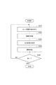
図6は、本実施形態に係る自動運転システム1における自動運転制御の処理の概要を示すフローチャートである。自動運転制御の処理は、自動運転制御の開始操作等により開始され、ECU10により実行される。   FIG. 6 is a flowchart showing an outline of the automatic driving control process in the automatic driving system 1 according to the present embodiment. The automatic driving control process is started by an automatic driving control starting operation or the like, and is executed by the ECU 10.

図6に示されるように、まず、センサ情報の読み込み処理が行われる(ステップS10)。この処理は、外部センサ2、GPS受信部3、内部センサ4、地図データベース5の情報を読み込む処理である。外部状況認識部11は、外部センサ2の検出情報を読み込み、その外部センサ2の検出情報に基づいて、道路幅、道路の形状、車両V周辺の他車両の走行状況、車両V周辺の障害物の状況等を認識する。また、車両位置認識部12は、GPS受信部3により測定された車両Vの位置情報及び地図データベース5の地図情報を読み込み、地図上における車両位置を認識する。さらに、走行状態認識部13は、内部センサ4の検出情報を読み込み、その検出情報に基づいて、車両Vの走行状態を認識する。車両Vの走行状態には、車速、加速度、ヨーレートが含まれる。   As shown in FIG. 6, first, sensor information reading processing is performed (step S10). This process is a process of reading information from the external sensor 2, the GPS receiver 3, the internal sensor 4, and the map database 5. The external situation recognition unit 11 reads the detection information of the external sensor 2, and based on the detection information of the external sensor 2, the road width, the shape of the road, the running situation of other vehicles around the vehicle V, and the obstacles around the vehicle V Recognize the situation. Further, the vehicle position recognition unit 12 reads the position information of the vehicle V measured by the GPS receiving unit 3 and the map information of the map database 5 and recognizes the vehicle position on the map. Further, the traveling state recognition unit 13 reads the detection information of the internal sensor 4 and recognizes the traveling state of the vehicle V based on the detection information. The traveling state of the vehicle V includes vehicle speed, acceleration, and yaw rate.

続いて、進路の生成処理が行われる(ステップS12)。進路の生成処理は、車両Vの目標進路を生成する処理である。このステップS12では、ナビゲーションシステム7で演算された目標ルート、外部状況認識部11で認識された車両Vの外部状況、車両位置認識部12で認識された車両位置、及び走行状態認識部13で認識された車両Vの走行状態に基づいて、進路生成部14が車両Vの目標進路を生成する。   Subsequently, a course generation process is performed (step S12). The course generation process is a process of generating a target course of the vehicle V. In this step S 12, the target route calculated by the navigation system 7, the external situation of the vehicle V recognized by the external situation recognition unit 11, the vehicle position recognized by the vehicle position recognition unit 12, and the travel state recognition unit 13 recognize it. Based on the travel state of the vehicle V, the route generation unit 14 generates a target route of the vehicle V.

続いて、走行計画の生成処理が行われる(ステップS14)。このステップS14では、車両位置認識部12で認識された車両位置、外部状況認識部11で認識された車両Vの外部状況、及び進路生成部14により生成された目標進路に基づいて、走行計画生成部15が目標進路上の位置に応じた車両Vの制御目標値を含む走行計画を生成する。   Subsequently, a travel plan generation process is performed (step S14). In step S14, a travel plan generation is performed based on the vehicle position recognized by the vehicle position recognition unit 12, the external situation of the vehicle V recognized by the external situation recognition unit 11, and the target course generated by the course generation unit 14. The unit 15 generates a travel plan including the control target value of the vehicle V according to the position on the target route.

続いて、運転制御処理が行われる(ステップS16)。運転制御処理は、ステップS14にて生成された走行計画に従って車両Vを走行させるように自動運転制御を行う処理である。運転制御部16は、アクチュエータ9に制御信号を出力する。これにより、アクチュエータ9が作動され、車両Vの操舵動作、駆動動作又は制動動作が行われ、車両Vが目標とする進路に沿って自動運転される。   Subsequently, an operation control process is performed (step S16). The driving control process is a process of performing automatic driving control so that the vehicle V travels according to the travel plan generated in step S14. The operation control unit 16 outputs a control signal to the actuator 9. As a result, the actuator 9 is actuated, and the steering operation, driving operation or braking operation of the vehicle V is performed, and the vehicle V is automatically driven along the target route.

そして、ステップS18に処理が移行し、自動運転制御が終了であるか否かが判定される。運転制御部16は、制御終了条件が成立する場合に自動運転制御を終了し、制御終了条件が成立しない場合には自動運転制御を継続する。制御終了条件としては、乗員により制御終了の操作が行われたこと、車両Vが制御終了地点に到着したこと等が該当する。S18にて自動運転制御の終了でないと判定された場合には、ステップS10に戻る。一方、ステップS18にて自動運転制御の終了であると判定された場合には、図4の一連の制御処理が終了する。   And a process transfers to step S18 and it is determined whether automatic driving | operation control is complete | finished. The operation control unit 16 ends the automatic operation control when the control end condition is satisfied, and continues the automatic operation control when the control end condition is not satisfied. The control end condition corresponds to a control end operation performed by an occupant, the vehicle V arriving at a control end point, or the like. If it is determined in S18 that the automatic operation control has not ended, the process returns to step S10. On the other hand, when it is determined in step S18 that the automatic driving control is finished, the series of control processes in FIG. 4 is finished.

図7は、進路生成部14による進路の生成処理を示すフローチャートである。進路の生成処理は、進路生成部14により実行され、自動運転制御の開始に伴って開始される。そして、進路の生成処理は、自動運転制御中において繰り返し実行され、自動運転制御の終了と共に終了する。   FIG. 7 is a flowchart showing a route generation process performed by the route generation unit 14. The route generation process is executed by the route generation unit 14 and is started with the start of the automatic operation control. Then, the course generation process is repeatedly executed during the automatic operation control, and ends with the end of the automatic operation control.

図7に示されるように、進路生成部14は、ナビゲーションシステム7で演算された目標ルートが存在するか否かを判定する(ステップS20)。ステップS20において目標ルートが存在すると判定された場合、進路生成部14は、目標ルートにおける目標進路を設定する(ステップS22)。   As shown in FIG. 7, the course generation unit 14 determines whether or not a target route calculated by the navigation system 7 exists (step S20). When it is determined in step S20 that the target route exists, the route generation unit 14 sets a target route in the target route (step S22).

ステップS20において目標ルートが存在しないと判定された場合、候補算出部141は、地図情報及び車両位置に基づいて、複数の進路候補を算出する(ステップS24)。続いて、候補評価部142は、ステップS22にて生成された複数の進路候補に対しての重み付けを予め設定された重みで行い、進路候補を評価する(ステップS26)。続いて、候補選択部143は、ステップS26での評価結果に基づいて、複数の進路候補を限定し、限定した進路候補をHMI8に表示させる(ステップS28)。   If it is determined in step S20 that the target route does not exist, the candidate calculation unit 141 calculates a plurality of route candidates based on the map information and the vehicle position (step S24). Subsequently, the candidate evaluation unit 142 performs weighting with respect to the plurality of course candidates generated in step S22 with a preset weight, and evaluates the course candidates (step S26). Subsequently, the candidate selection unit 143 limits a plurality of course candidates based on the evaluation result in step S26, and displays the limited course candidates on the HMI 8 (step S28).

続いて、候補選択部143は、方向指示器6での受け付け結果に基づいて、ドライバによる進路候補の選択が存在するか否かを判定する(ステップS30)。ステップS30においてドライバによる進路候補の選択が存在すると判定された場合、進路生成部14は、ドライバが選択した進路候補により目標進路を設定する(ステップS32)。ステップS30においてドライバによる進路候補の選択が存在しないと判定された場合、進路生成部14は、基準進路候補を運転者が選択したものとして、進路候補の評価に基づき、付与された重み値の合計が最も大きい進路候補により目標進路を設定する(ステップS34)。   Subsequently, the candidate selection unit 143 determines whether or not there is a selection of a course candidate by the driver based on the reception result by the direction indicator 6 (step S30). When it is determined in step S30 that there is a selection of a route candidate by the driver, the route generation unit 14 sets a target route based on the route candidate selected by the driver (step S32). When it is determined in step S30 that there is no selection of a route candidate by the driver, the route generation unit 14 assumes that the driver has selected a reference route candidate and sums the weight values given based on the evaluation of the route candidate. A target course is set by a course candidate having the largest (step S34).

以上説明したように、本実施形態に係る自動運転システム1によれば、候補算出部141が複数の進路候補を算出する。算出した進路候補に対して重み付けを予め設定された重みで行うことで、候補評価部142が進路候補を評価する。候補評価部142での評価結果に基づいて、候補選択部143が複数の進路候補を限定し、限定された進路候補をHMI8に表示させる。すなわち、HMI8に表示される進路候補の数が制限される。この結果、目的地が予め設定されていない場合において、ドライバが進路候補を選択することが簡便となる。従って、自動運転システム1は、目的地が設定されていない場合において利便性が高い。   As described above, according to the automatic driving system 1 according to the present embodiment, the candidate calculation unit 141 calculates a plurality of course candidates. The candidate evaluation unit 142 evaluates the route candidate by performing weighting on the calculated route candidate with a preset weight. Based on the evaluation result in the candidate evaluation unit 142, the candidate selection unit 143 limits a plurality of course candidates and causes the HMI 8 to display the limited course candidates. That is, the number of course candidates displayed on the HMI 8 is limited. As a result, when the destination is not set in advance, it is easy for the driver to select a course candidate. Therefore, the automatic driving system 1 is highly convenient when the destination is not set.

なお、上述した実施形態は、本発明に係る自動運転システムの一実施形態を説明したものであり、本発明に係る自動運転システムは上記実施形態に記載されたものに限定されない。本発明に係る自動運転システムは、請求項に記載した要旨を変更しないように上記実施形態に係る自動運転システムを変形し、又は他のものに適用したものであってもよい。   In addition, embodiment mentioned above demonstrated one Embodiment of the automatic driving system which concerns on this invention, and the automatic driving system which concerns on this invention is not limited to what was described in the said embodiment. The automatic driving system according to the present invention may be obtained by modifying the automatic driving system according to the above-described embodiment so as not to change the gist described in the claims, or by applying it to others.

上記実施形態では、候補選択部143は、図4及び図5で例示した連続する2つの分岐部B21,B22における進路候補L21〜L24を、図8及び図9に示されるように矢印アイコンで進路候補を表現してHMI8の表示領域81及び表示領域82に表示させてもよい。候補選択部143は、分岐部B21において特定された進行方向を表示領域81に表示し、分岐部B22において特定された進行方向を表示領域82に表示する。進路候補は、表示領域81に表示された進行方向と表示領域82に表示された進行方向との組み合わせにより表現される。矢印アイコンは、分岐部において特定された進行方向に対応する車両Vの動作方向(例えば左折、直進、右折等)を指し示す図形である。矢印アイコンは、進路候補に応じて表示領域81及び表示領域82に表示される。選択された進路候補に対応する矢印アイコンは、選択されていない進路候補に対応する矢印アイコンとは異なる色彩で表示される。   In the embodiment described above, the candidate selection unit 143 uses the arrow icons as shown in FIGS. 8 and 9 to indicate the course candidates L21 to L24 in the two consecutive branch parts B21 and B22 illustrated in FIGS. Candidates may be expressed and displayed in the display area 81 and the display area 82 of the HMI 8. The candidate selection unit 143 displays the traveling direction specified in the branching section B21 in the display area 81, and displays the traveling direction specified in the branching section B22 in the display area 82. The course candidate is expressed by a combination of the traveling direction displayed in the display area 81 and the traveling direction displayed in the display area 82. The arrow icon is a graphic indicating the operation direction (for example, left turn, straight advance, right turn, etc.) of the vehicle V corresponding to the traveling direction specified in the branching portion. The arrow icon is displayed in the display area 81 and the display area 82 according to the course candidate. The arrow icon corresponding to the selected course candidate is displayed in a different color from the arrow icon corresponding to the unselected course candidate.

図8の(a)の例では、図4の(a)の例と同様、候補選択部143が進路候補L21〜L24をHMI8に表示させており、進路候補L22がドライバにより選択されている。進路候補L22は、分岐部B21での左折を意味する表示領域81の矢印アイコンと、その後の分岐部B22での右折を意味する表示領域82の矢印アイコンと、により表現されている。   In the example of FIG. 8A, as in the example of FIG. 4A, the candidate selection unit 143 displays the route candidates L21 to L24 on the HMI 8, and the route candidate L22 is selected by the driver. The course candidate L22 is represented by an arrow icon in the display area 81 that signifies a left turn at the branch B21 and an arrow icon in the display area 82 that signifies a right turn at the subsequent branch B22.

図8の(b)は、図8の(a)においてドライバによる1回の右方選択操作を方向指示器6が受け付けた場合を示している。つまり、図8の(b)の例では、図8の(a)において選択していた進路候補L22の1つ右側の進路候補L23がドライバにより選択されている。候補選択部143は、分岐部B21での直進を意味する表示領域81の矢印アイコンを、選択されていない進路候補に対応する矢印アイコンとは異なる色彩で表示させる。この場合、進路候補L23は分岐部B21の先の分岐部において特定される進行方向を含まないため、143は、表示領域82には特に何も表示させない。   FIG. 8B shows a case where the direction indicator 6 receives one right selection operation by the driver in FIG. 8A. That is, in the example of FIG. 8B, the route candidate L23 on the right side of the route candidate L22 selected in FIG. 8A is selected by the driver. The candidate selection part 143 displays the arrow icon of the display area 81 which means the straight advance in the branch part B21 by the color different from the arrow icon corresponding to the course candidate which has not been selected. In this case, since the course candidate L23 does not include the traveling direction specified in the branch part ahead of the branch part B21, the display area 82 displays nothing in particular.

その後、車両Vが分岐部B21に到達すると、図9の(a)に示されるように、車両Vが進路候補L23に沿って自動走行している状態として、候補選択部143は、分岐部B21での直進を意味する表示領域81の矢印アイコンを、図8の(b)における当該矢印アイコンの色彩とは異なる色彩で表示させる。その後、車両Vが進路候補L23を通り抜けると、図9の(b)に示されるように、候補選択部143は、分岐部B21の先に存在する分岐部において特定された進行方向をHMI8に表示させる。   Thereafter, when the vehicle V reaches the branching section B21, as shown in FIG. 9A, the candidate selecting section 143 sets the branching section B21 as a state in which the vehicle V is automatically traveling along the route candidate L23. The arrow icon in the display area 81 that means straight traveling at is displayed in a color different from the color of the arrow icon in FIG. Thereafter, when the vehicle V passes through the route candidate L23, as shown in FIG. 9B, the candidate selection unit 143 displays the traveling direction specified at the branch portion existing ahead of the branch portion B21 on the HMI 8. Let

図8及び図9の例において、選択された進路候補に対応する矢印アイコンは、色彩以外の要素において、選択されていない進路候補に対応する矢印アイコンとは異なるように表示されてもよい。なお、上記実施形態の図4及び図5の例において、選択された進路候補L22は、色彩及び太さ以外の要素において、選択されていない進路候補L21,L23,L24とは異なるように表示されてもよい。   In the examples of FIGS. 8 and 9, the arrow icon corresponding to the selected route candidate may be displayed differently from the arrow icon corresponding to the unselected route candidate in elements other than color. In the example of FIGS. 4 and 5 of the above embodiment, the selected route candidate L22 is displayed differently from the unselected route candidates L21, L23, and L24 in elements other than color and thickness. May be.

上記実施形態では、候補選択部143は、限定された進路候補をHMI8に表示させたが、限定された進路候補を表示する第1モードと、第1モードとは異なる個数の進路候補を表示する第2モードと、を乗員の切替要求に応じて切り替えてHMI8に表示させてもよい。これにより、限定された進路候補が乗員の期待に沿っていない場合であっても、HMI8に表示される進路候補の個数を乗員の切替要求に応じて変更することができる。   In the above embodiment, the candidate selection unit 143 displays the limited course candidates on the HMI 8, but the first mode for displaying the limited course candidates and the number of course candidates different from the first mode are displayed. The second mode may be switched according to a passenger switching request and displayed on the HMI 8. Thereby, even when the limited course candidate does not meet the occupant's expectation, the number of course candidates displayed on the HMI 8 can be changed according to the occupant switching request.

この場合、第2モードは、第1モードよりも多い進路候補を表示する態様であってもよい。第2モードは、予め設定した第1モードよりも多い個数の進路候補を表示するモードであってもよい。第2モードは、候補算出部141にて算出した進路候補を全て表示するモードであってもよい。   In this case, the second mode may be a mode that displays more course candidates than the first mode. The second mode may be a mode that displays a larger number of course candidates than the preset first mode. The second mode may be a mode in which all the course candidates calculated by the candidate calculation unit 141 are displayed.

第2モードは、第1モードよりも少ない進路候補を表示する態様であってもよい。第2モードは、予め設定した第1モードよりも少ない個数の進路候補を表示するモードであってもよい。第2モードは、付与された重み値の合計が最も大きい進路候補のみを表示する態様であってもよい。第2モードは、進路候補を表示しない(0個の進路候補を表示する)態様であってもよい。例えば、候補選択部143は、上述した乗員の切替要求が取得されるまでは、第2モードで進路候補をHMI8に表示させてもよい。   The second mode may be a mode in which fewer route candidates are displayed than in the first mode. The second mode may be a mode that displays a smaller number of course candidates than the preset first mode. The second mode may be a mode in which only the route candidate having the largest sum of the assigned weight values is displayed. The second mode may be a mode in which no route candidate is displayed (zero route candidates are displayed). For example, the candidate selection unit 143 may display the course candidates on the HMI 8 in the second mode until the above-described occupant switching request is acquired.

第1モード及び第2モードは、進路候補を所定の条件でグループ分けした進路候補を表示する態様であってもよい。この場合、第1モードに含まれる進路候補と、第2モードに含まれる進路候補との重複があってもよい。   The first mode and the second mode may be a mode in which the route candidates obtained by grouping the route candidates under a predetermined condition are displayed. In this case, there may be overlap between the course candidate included in the first mode and the course candidate included in the second mode.

候補選択部143は、これらの場合における乗員の切替要求を、以下のようにして取得する。候補選択部143は、乗員が第1モード又は第2モードを選択可能なモードスイッチをHMI8に表示させる。候補選択部143は、HMI8を介した乗員の入力操作により乗員の切替要求を取得する。候補選択部143は、HMI8に表示させる進路候補の数を指定する乗員の入力操作に基づいて、乗員の切替要求を取得してもよい。候補選択部143は、ドライバによる方向指示器6の操作(例えばウインカレバーを上に押し上げる操作)に基づいて、乗員の切替要求を取得してもよい。   The candidate selection unit 143 acquires the occupant switching request in these cases as follows. The candidate selection unit 143 causes the HMI 8 to display a mode switch that allows the occupant to select the first mode or the second mode. The candidate selection unit 143 acquires an occupant switching request by an occupant input operation via the HMI 8. Candidate selection unit 143 may acquire an occupant switching request based on an occupant input operation that specifies the number of course candidates to be displayed on HMI 8. Candidate selection unit 143 may acquire an occupant switching request based on an operation of direction indicator 6 by the driver (for example, an operation of pushing the winker lever upward).

上記実施形態において、候補選択部143は、一旦停止の標識が設けられた交差点又は信号が設けられた交差点でのみHMI8に進路候補を表示させる第3モードと、候補算出部141にて算出した進路候補を全ての分岐部において表示する第4モードと、を乗員の切替要求に応じて切り替えてHMI8に表示させてもよい。候補選択部143は、この場合における乗員の切替要求を以下のようにして取得する。候補選択部143は、乗員が第3モードと第4モードとを選択可能なモードスイッチをHMI8に表示させる。候補選択部143は、HMI8を介した乗員の入力操作により乗員の切替要求を取得する。   In the above embodiment, the candidate selection unit 143 has the third mode in which the route candidates are displayed on the HMI 8 only at the intersection where the stop sign is provided or the intersection where the signal is provided, and the route calculated by the candidate calculation unit 141. The fourth mode in which candidates are displayed in all the branch portions may be switched according to a passenger switching request and displayed on the HMI 8. The candidate selection unit 143 acquires the occupant switching request in this case as follows. Candidate selection unit 143 causes HMI 8 to display a mode switch that allows the occupant to select between the third mode and the fourth mode. The candidate selection unit 143 acquires an occupant switching request by an occupant input operation via the HMI 8.

上記実施形態では、自動運転システム1が、入力部として方向指示器6を備えているが、例えば、入力部として、操舵角センサを備えていてもよい。この場合、操舵角センサは、ドライバによる操舵操作を乗員による入力操作として受け付ける。自動運転システム1が、入力部として、ドライバ撮像カメラと、視線検出部と、を備えていてもよい。この場合、視線検出部は、ドライバ撮像カメラからの出力に基づいて、ドライバの視線変化を検出し、この視線変化を乗員による入力操作として受け付ける。自動運転システム1が、入力部として、ACC[Adaptive Cruise Control]レバーと、ACCレバー操作検出部と、を備えていてもよい。この場合、ACCレバー操作検出部は、ドライバによるACCレバーの操作を乗員による入力操作として受け付ける。入力部は、HMI8の操作ボタン、操作レバー、タッチパネル、又は新規に設けられたボタンやパッド等であってもよい。この場合、入力部は、ドライバ以外の乗員による進路候補の選択操作を受け付けることが可能となる。   In the said embodiment, although the automatic driving system 1 is provided with the direction indicator 6 as an input part, for example, you may be provided with the steering angle sensor as an input part. In this case, the steering angle sensor accepts a steering operation by the driver as an input operation by the occupant. The automatic driving system 1 may include a driver imaging camera and a line-of-sight detection unit as input units. In this case, the line-of-sight detection unit detects a change in the line of sight of the driver based on the output from the driver imaging camera, and accepts the change in the line of sight as an input operation by the occupant. The automatic driving system 1 may include an ACC [Adaptive Cruise Control] lever and an ACC lever operation detection unit as input units. In this case, the ACC lever operation detection unit accepts an operation of the ACC lever by the driver as an input operation by the occupant. The input unit may be an operation button, an operation lever, a touch panel, or a newly provided button or pad of the HMI 8. In this case, the input unit can accept a route candidate selection operation by an occupant other than the driver.

候補評価部142は、進路候補ごとに重み値を合計し、合計した重み値を比較することにより、予め設定された重みでの重み付けを行っているが、重み係数を含む多項式で定義される関数を進路候補ごとに設定し、関数の値を比較することにより、予め設定された重みでの重み付けを行ってもよい。この場合、重み係数は、重み条件ごとに設定され、重み条件に対応付けられた重み係数である。進路候補が重み条件を満たす場合の重み係数は、例えば、進路候補が重み条件を満たさない場合の重み係数よりも大きく設定される。   The candidate evaluation unit 142 performs weighting with a preset weight by adding the weight values for each course candidate and comparing the total weight values, but the function is defined by a polynomial including a weight coefficient. May be set for each course candidate, and weighting with a preset weight may be performed by comparing function values. In this case, the weighting factor is a weighting factor set for each weighting condition and associated with the weighting condition. For example, the weighting factor when the route candidate satisfies the weight condition is set to be larger than the weighting factor when the route candidate does not satisfy the weighting condition.

1…自動運転システム、5…地図データベース、6…方向指示器(入力部)、8…HMI(表示部)、12…車両位置認識部、14…進路生成部、15…走行計画生成部、141…候補算出部、142…候補評価部、143…候補選択部。   DESCRIPTION OF SYMBOLS 1 ... Automatic driving system, 5 ... Map database, 6 ... Direction indicator (input part), 8 ... HMI (display part), 12 ... Vehicle position recognition part, 14 ... Course generation part, 15 ... Travel plan generation part, 141 ... candidate calculation unit, 142 ... candidate evaluation unit, 143 ... candidate selection unit.

Claims (1)

目的地が予め設定されていない場合に車両の走行計画を生成し、前記走行計画に基づいて前記車両の自動運転制御を行う自動運転システムであって、
前記車両の乗員による入力操作を受け付ける入力部と、
前記乗員に情報を表示する表示部と、
地図情報を記憶した地図データベースと、
前記車両の車両位置を認識する車両位置認識部と、
前記地図情報及び前記車両位置に基づいて、複数の進路候補を算出する候補算出部と、
前記複数の進路候補に対しての重み付けを予め設定された重みで行い、前記複数の進路候補を評価する候補評価部と、
前記候補評価部での評価結果に基づいて、前記複数の進路候補を限定し、限定した前記進路候補を前記表示部に表示させ、前記入力部での受け付け結果に基づいて、前記表示部に表示された前記進路候補のうち前記乗員により選択された進路候補を認識する候補選択部と、
前記候補選択部にて認識された前記進路候補を目標進路として、当該目標進路上の位置に応じた前記車両の制御目標値を含む前記走行計画を生成する走行計画生成部と、
を備える、自動運転システム。
An automatic driving system that generates a travel plan of a vehicle when a destination is not set in advance, and performs automatic driving control of the vehicle based on the travel plan,
An input unit for receiving an input operation by a passenger of the vehicle;
A display unit for displaying information to the passenger;
A map database storing map information;
A vehicle position recognition unit for recognizing the vehicle position of the vehicle;
A candidate calculating unit that calculates a plurality of course candidates based on the map information and the vehicle position;
A candidate evaluation unit that performs weighting on the plurality of course candidates with a preset weight and evaluates the plurality of course candidates;
Based on the evaluation result in the candidate evaluation unit, the plurality of course candidates are limited, the limited course candidate is displayed on the display unit, and displayed on the display unit based on the reception result in the input unit A candidate selection unit for recognizing a route candidate selected by the occupant among the route candidates
A travel plan generation unit that generates the travel plan including the control target value of the vehicle according to the position on the target route, with the route candidate recognized by the candidate selection unit as a target route;
An automatic driving system comprising:
JP2016037873A 2016-02-29 2016-02-29 Automatic driving system Pending JP2017156874A (en)

Priority Applications (1)

Application Number Priority Date Filing Date Title
JP2016037873A JP2017156874A (en) 2016-02-29 2016-02-29 Automatic driving system

Applications Claiming Priority (1)

Application Number Priority Date Filing Date Title
JP2016037873A JP2017156874A (en) 2016-02-29 2016-02-29 Automatic driving system

Publications (1)

Publication Number Publication Date
JP2017156874A true JP2017156874A (en) 2017-09-07

Family

ID=59809767

Family Applications (1)

Application Number Title Priority Date Filing Date
JP2016037873A Pending JP2017156874A (en) 2016-02-29 2016-02-29 Automatic driving system

Country Status (1)

Country Link
JP (1) JP2017156874A (en)

Citations (7)

* Cited by examiner, † Cited by third party
Publication number Priority date Publication date Assignee Title
JP2011162132A (en) * 2010-02-12 2011-08-25 Toyota Motor Corp Automatic driving device
WO2011158347A1 (en) * 2010-06-16 2011-12-22 トヨタ自動車株式会社 Driving assistance device
WO2014054536A1 (en) * 2012-10-03 2014-04-10 日産自動車株式会社 On-board device and navigation method
JP2014163793A (en) * 2013-02-25 2014-09-08 Nissan Motor Co Ltd Route search system
JP2015148533A (en) * 2014-02-07 2015-08-20 日産自動車株式会社 Vehicle route selection apparatus and vehicle route selection method
WO2015141308A1 (en) * 2014-03-18 2015-09-24 日産自動車株式会社 Vehicle operation device
JP2015227785A (en) * 2014-05-30 2015-12-17 日産自動車株式会社 Route information presentation system

Patent Citations (7)

* Cited by examiner, † Cited by third party
Publication number Priority date Publication date Assignee Title
JP2011162132A (en) * 2010-02-12 2011-08-25 Toyota Motor Corp Automatic driving device
WO2011158347A1 (en) * 2010-06-16 2011-12-22 トヨタ自動車株式会社 Driving assistance device
WO2014054536A1 (en) * 2012-10-03 2014-04-10 日産自動車株式会社 On-board device and navigation method
JP2014163793A (en) * 2013-02-25 2014-09-08 Nissan Motor Co Ltd Route search system
JP2015148533A (en) * 2014-02-07 2015-08-20 日産自動車株式会社 Vehicle route selection apparatus and vehicle route selection method
WO2015141308A1 (en) * 2014-03-18 2015-09-24 日産自動車株式会社 Vehicle operation device
JP2015227785A (en) * 2014-05-30 2015-12-17 日産自動車株式会社 Route information presentation system

Similar Documents

Publication Publication Date Title
US10293748B2 (en) Information presentation system
US9679488B2 (en) Drive assistance apparatus
EP3580625B1 (en) Driving scenario based lane guidelines for path planning of autonomous driving vehicles
US9802623B2 (en) Autonomous driving device
US9914458B2 (en) Control system of automated driving vehicle
JP6269534B2 (en) Travel control device
RU2641023C2 (en) Driving assistance system
JP6269552B2 (en) Vehicle travel control device
US9896098B2 (en) Vehicle travel control device
JP6705388B2 (en) Automatic driving system
US10496098B2 (en) Road segment-based routing guidance system for autonomous driving vehicles
US10261516B2 (en) Vehicle control device
US11685398B2 (en) Lane based routing system for autonomous driving vehicles
JP6809611B2 (en) Driving support method and driving support device
US11433897B2 (en) Method and apparatus for determination of optimal cruising lane in an assisted driving system
US10845814B2 (en) Host vehicle position confidence degree calculation device
CN113247017B (en) Double buffer system for ensuring stable detour of an autonomous vehicle
US11407419B2 (en) Central line shifting based pre-change lane path planning
US11254326B2 (en) Automatic comfort score system based on human driving reference data
WO2021189350A1 (en) A point cloud-based low-height obstacle detection system
JP2017156874A (en) Automatic driving system

Legal Events

Date Code Title Description
A621 Written request for application examination

Free format text: JAPANESE INTERMEDIATE CODE: A621

Effective date: 20180724

A131 Notification of reasons for refusal

Free format text: JAPANESE INTERMEDIATE CODE: A131

Effective date: 20190702

A977 Report on retrieval

Free format text: JAPANESE INTERMEDIATE CODE: A971007

Effective date: 20190628

A521 Request for written amendment filed

Free format text: JAPANESE INTERMEDIATE CODE: A523

Effective date: 20190829

A02 Decision of refusal

Free format text: JAPANESE INTERMEDIATE CODE: A02

Effective date: 20200204