JP2017147594A - Audio apparatus - Google Patents
Audio apparatus Download PDFInfo
- Publication number
- JP2017147594A JP2017147594A JP2016027882A JP2016027882A JP2017147594A JP 2017147594 A JP2017147594 A JP 2017147594A JP 2016027882 A JP2016027882 A JP 2016027882A JP 2016027882 A JP2016027882 A JP 2016027882A JP 2017147594 A JP2017147594 A JP 2017147594A
- Authority
- JP
- Japan
- Prior art keywords
- video
- delay time
- signal
- audio
- delay
- Prior art date
- Legal status (The legal status is an assumption and is not a legal conclusion. Google has not performed a legal analysis and makes no representation as to the accuracy of the status listed.)
- Granted
Links
- 230000005236 sound signal Effects 0.000 claims description 39
- 238000004891 communication Methods 0.000 claims description 12
- 230000003111 delayed effect Effects 0.000 claims description 8
- 230000001934 delay Effects 0.000 claims description 4
- 230000005540 biological transmission Effects 0.000 abstract description 14
- 239000000872 buffer Substances 0.000 description 9
- 238000000034 method Methods 0.000 description 7
- 230000001360 synchronised effect Effects 0.000 description 6
- 230000004044 response Effects 0.000 description 3
- 230000003139 buffering effect Effects 0.000 description 2
- 238000010586 diagram Methods 0.000 description 2
- 238000007796 conventional method Methods 0.000 description 1
- 230000006870 function Effects 0.000 description 1
- 230000011664 signaling Effects 0.000 description 1
Images

Classifications
-
- H—ELECTRICITY
- H04—ELECTRIC COMMUNICATION TECHNIQUE
- H04N—PICTORIAL COMMUNICATION, e.g. TELEVISION
- H04N21/00—Selective content distribution, e.g. interactive television or video on demand [VOD]
- H04N21/40—Client devices specifically adapted for the reception of or interaction with content, e.g. set-top-box [STB]; Operations thereof
- H04N21/43—Processing of content or additional data, e.g. demultiplexing additional data from a digital video stream; Elementary client operations, e.g. monitoring of home network or synchronising decoder's clock; Client middleware
- H04N21/436—Interfacing a local distribution network, e.g. communicating with another STB or one or more peripheral devices inside the home
-
- H—ELECTRICITY
- H04—ELECTRIC COMMUNICATION TECHNIQUE
- H04N—PICTORIAL COMMUNICATION, e.g. TELEVISION
- H04N21/00—Selective content distribution, e.g. interactive television or video on demand [VOD]
- H04N21/40—Client devices specifically adapted for the reception of or interaction with content, e.g. set-top-box [STB]; Operations thereof
- H04N21/43—Processing of content or additional data, e.g. demultiplexing additional data from a digital video stream; Elementary client operations, e.g. monitoring of home network or synchronising decoder's clock; Client middleware
- H04N21/44—Processing of video elementary streams, e.g. splicing a video clip retrieved from local storage with an incoming video stream or rendering scenes according to encoded video stream scene graphs
-
- H—ELECTRICITY
- H04—ELECTRIC COMMUNICATION TECHNIQUE
- H04N—PICTORIAL COMMUNICATION, e.g. TELEVISION
- H04N21/00—Selective content distribution, e.g. interactive television or video on demand [VOD]
- H04N21/80—Generation or processing of content or additional data by content creator independently of the distribution process; Content per se
- H04N21/85—Assembly of content; Generation of multimedia applications
- H04N21/854—Content authoring
- H04N21/8547—Content authoring involving timestamps for synchronizing content
Landscapes
- Engineering & Computer Science (AREA)
- Multimedia (AREA)
- Signal Processing (AREA)
- Computer Security & Cryptography (AREA)
- Two-Way Televisions, Distribution Of Moving Picture Or The Like (AREA)
- Television Signal Processing For Recording (AREA)
- Television Receiver Circuits (AREA)
Abstract
Description
この発明は、複数系統の音声を映像に同期させるオーディオ機器に関する。 The present invention relates to an audio device that synchronizes a plurality of audio lines with video.
映像と音声とを同期して再生する場合、一般に映像の処理により時間を要するため、音声信号を所定時間遅延させて映像の遅れに同期させている。この同期処理は、リップシンクと呼ばれる。 When video and audio are reproduced in synchronism, since it generally takes time to process the video, the audio signal is delayed by a predetermined time to synchronize with the video delay. This synchronization process is called lip sync.
さらに、映像と音声とが別の機器で再生される場合には、映像機器がオーディオ機器に対して、映像の遅延時間を知らせ、オーディオ機器がそれに合わせて音声を遅延させる必要がある。この処理は、ダイナミック自動リップシンクと呼ばれる(特許文献1参照)。 Furthermore, when video and audio are reproduced by different devices, the video device needs to inform the audio device of the delay time of the video, and the audio device needs to delay the audio accordingly. This process is called dynamic automatic lip sync (see Patent Document 1).
このように、従来より、映像および音声の再生において両者の同期をとるための技術が存在するが、音声がさらに別の機器に分岐して配信される場合、たとえば、オーディオ機器からさらにワイヤレスのパワードスピーカに配信される場合などには、この分岐された音声の放音タイミングを同期させることはできなかった。 As described above, there is a conventional technique for synchronizing both video and audio reproduction. However, when audio is branched and distributed to another device, for example, an audio device further powers wirelessly. For example, when the sound is distributed to a speaker, the sound output timing of the branched sound cannot be synchronized.
この発明は、映像と複数系統で出力される音声とを同期させることのできるオーディオ機器を提供することを目的とする。 An object of this invention is to provide the audio equipment which can synchronize the image | video and the audio | voice output by multiple systems.
本発明のオーディオ機器は、映像信号および音声信号を入力する信号入力部と、音声信号を遅延させて出力する信号処理部と、映像再生機器に対して映像信号を送信する信号出力部と、他のオーディオ機器に音声信号を放音時刻を指示するタイムスタンプを付して無線で送信する通信部と、制御部と、を備える。制御部は、信号出力部を介して、映像再生機器から映像遅延時間を取得し、通信部から配信遅延時間を取得し、映像遅延時間が配信遅延時間以上の場合、信号処理部の遅延時間を映像遅延時間と同じに設定するとともに、通信部が送信する音声信号に映像遅延時間だけ遅延させるタイムスタンプを付す。 The audio device of the present invention includes a signal input unit that inputs a video signal and an audio signal, a signal processing unit that outputs the audio signal with a delay, a signal output unit that transmits the video signal to the video reproduction device, and the like. A communication unit that wirelessly transmits an audio signal to the audio device with a time stamp indicating the sound emission time, and a control unit. The control unit obtains the video delay time from the video playback device via the signal output unit, acquires the delivery delay time from the communication unit, and if the video delay time is equal to or greater than the delivery delay time, the control unit obtains the delay time of the signal processing unit. The time stamp is set to be the same as the video delay time, and the audio signal transmitted by the communication unit is delayed by the video delay time.
制御部は、映像遅延時間が配信遅延時間よりも小さい場合、映像信号の種類またはユーザによる選択に応じて、信号処理部の遅延時間を映像遅延時間または配信遅延時間のいずれかと同じに設定し、通信部が送信する音声信号に配信遅延時間だけ遅延させるタイムスタンプを付すようにしてもよい。 When the video delay time is smaller than the delivery delay time, the control unit sets the delay time of the signal processing unit to be the same as either the video delay time or the delivery delay time according to the type of the video signal or the selection by the user, You may make it attach the time stamp which delays only the delivery delay time to the audio | voice signal which a communication part transmits.
制御部は、信号処理部の遅延時間を配信遅延時間と同じに設定した場合、信号出力部を介して映像再生機器に対して、映像遅延時間を配信遅延時間と同じに設定するよう指示してもよい。 When the delay time of the signal processing unit is set to be the same as the delivery delay time, the control unit instructs the video playback device to set the video delay time to be the same as the delivery delay time via the signal output unit. Also good.
この発明によれば、映像再生に遅延を持たないオーディオ機器にハードを追加せずに、映像再生機器で表示される映像と、オーディオ機器自身で再生される音声、および、他のオーディオ機器で再生される音声と、を同期させることが可能になる。 According to the present invention, without adding hardware to an audio device having no delay in video playback, video displayed on the video playback device, audio played back on the audio device itself, and playback on other audio devices It is possible to synchronize with the voice to be played.
図1はこの発明の実施形態であるオーディオシステム1の構成図である。オーディオシステム1は、レシーバ1,パワードスピーカ2,BD(ブルーレイ・ディスク)プレーヤ3、および、テレビ(TV)4を有している。テレビ4は、BDプレーヤ3で再生された映像を表示するディスプレイとして機能する。
FIG. 1 is a configuration diagram of an audio system 1 according to an embodiment of the present invention. The audio system 1 includes a receiver 1, powered
レシーバ1は、制御部10、HDMI(High−Definition Multimedia Interface)受信部11、信号処理部12、アンプ13、HDMI送信部14、および、ネットワークモジュール15を有している。制御部10は、HDMI受信部11、信号処理部12、アンプ13、HDMI送信部14、および、ネットワークモジュール15を含むレシーバ1全体の動作を制御する。HDMI受信部11は、BDプレーヤ3に接続され、BDプレーヤ3から出力される映像信号を受信する。BDプレーヤ3から出力される映像信号には音声信号が含まれる。HDMI受信部11には、信号処理部12、HDMI送信部14およびネットワークモジュール15が接続されている。HDMI送信部14には、テレビ4が接続される。
The receiver 1 includes a
BDプレーヤ3は、映画などの映像ソースを再生して映像信号を出力する。HDMI受信部11がBDプレーヤ3から受信した映像信号は、そのままHDMI送信部14に転送される。さらに、映像信号から取り出された音声信号が信号処理部12およびネットワークモジュール15に入力される。
The
信号処理部12は、デジタル・シグナル・プロセッサ(DSP)を含んでおり、HDMI受信部11が受信した映像信号から取り出された音声信号に対してサラウンド等の信号処理を行う。信号処理部12におけるこの信号処理は、所定の処理時間を要する。さらに、信号処理部12は、音声信号をバッファするバッファメモリを内蔵または外付けで備えており、テレビ4やパワードスピーカ3などの他の出力装置と同期をとるために、さらに制御部10から指定された時間音声信号を遅延させることができる。この信号処理部12における処理による遅延時間および指定された遅延時間を加えた遅延時間を、以下、遅延時間(音声遅延)DAと呼ぶ。
The
信号処理部12には、アンプ13が接続されている。信号処理部12は、サラウンド処理などを施した音声信号をアンプ13に出力する。アンプ13はこの音声信号を増幅してスピーカ16に出力する。スピーカ16は、レシーバ1の端子(不図示)に接続された外付けのスピーカ装置である。スピーカ16は、この音声信号を音響として放音する。以上により、音声信号は、映像信号に含まれてHDMI受信部11で受信されたのち、遅延時間DAだけ遅延されてスピーカ16から放音される。
An
HDMI送信部14は、HDMI受信部11から転送されてきた映像信号をテレビ4に送信する。HDMI受信部11とHDMI送信部13との間はパススルーであり、映像信号に対する加工等の信号処理は行われない。HDMI送信部13は、テレビ4に対して映像信号をTMDS(Transition−minimized differential signaling)方式で送信するとともに、テレビ4とレシーバ1との間でCEC(Consumer Electronics Control)手順で相互に制御情報を送受信する。テレビ4から送られてくる制御情報には、ダイナミック自動リップシンクの情報が含まれる。
The
テレビ4は、レシーバ1から受信した映像信号をデコードし、その映像の種類に応じた映像処理を行ってLCDディスプレイに表示する。映像の種類とは、たとえば、通常の映像、4K映像、3D映像などであり、映像の種類によってその処理時間が異なる。テレビ4は、レシーバ1から送られてきた映像信号から映像の種類を判断して、必要な処理時間を判断し、その処理時間をダイナミック自動リップシンク情報としてHDMIのCEC経由でレシーバ1に返信する。この処理時間が映像遅延(遅延時間)DVであり、一般的に30〜150ミリ秒程度である。 The television 4 decodes the video signal received from the receiver 1, performs video processing corresponding to the type of the video, and displays it on the LCD display. Examples of the video type include normal video, 4K video, 3D video, and the like, and the processing time differs depending on the video type. The TV 4 determines the type of video from the video signal sent from the receiver 1, determines the necessary processing time, and returns the processing time to the receiver 1 via HDMI CEC as dynamic automatic lip sync information. . This processing time is a video delay (delay time) DV, which is generally about 30 to 150 milliseconds.
ネットワークモジュール15は、パワードスピーカ2に対してワイヤレスで音声信号を送信する。パワードスピーカ2は、音声信号を受信するネットワークモジュール21、音声信号を増幅するアンプ22、および、音声信号を音響として放音するスピーカユニット23を有する。パワードスピーカ2のネットワークモジュール21は、通信が一時途切れた場合でも再生音を途切れさせないように十分な容量のバッファを有しており、レシーバ1のネットワークモジュール15から音声信号の受信を開始したのち、バッファに所定量以上の音声信号がバッファされた状態で音声信号の再生を開始する。したがって、パワードスピーカ2による音声信号の再生は、無線による伝送の所要時間(衝突制御、再送制御など)、および、音声信号のバッファによって遅延する。この遅延時間(配信遅延)DNは、100〜200ミリ秒程度である。無線による音声信号の伝送は、Bluetoothなどの汎用の方式であってもよく、または、独自の方式を用いてもよい。
The
レシーバ1(ネットワークモジュール15)は、パワードスピーカ2(ネットワークモジュール21)に対して、パケット化した音声信号を送信する。レシーバ1は、各パケットにそのパケット内の音声信号が再生されるべき時刻(タイムスタンプ)を付して送信する。パワードスピーカ2は、受信したパケットの音声信号をバッファし、これをタイムスタンプで指定された時刻に再生する。タイムスタンプは、配信遅延DNを見越して音声信号の送信時から100〜200ミリ秒先に設定される。すなわち、音声信号の再生が100〜200ミリ秒遅延される。また、ネットワークモジュール15、21が有線LAN接続が可能である場合、レシーバ1とパワードスピーカ2とを有線LANで接続して配信遅延DNを数十ミリ秒程度に小さくすることができる。なお、この遅延量(配信遅延DN)は、パワードスピーカ2のバッファの容量が許す範囲内で大きくすることが可能である。配信遅延DNを大きさ次第では、パワードスピーカ2による音声信号の放音をテレビ4の映像と同期をとることが可能になる。
The receiver 1 (network module 15) transmits the packetized audio signal to the powered speaker 2 (network module 21). The receiver 1 transmits each packet with a time (time stamp) at which the audio signal in the packet is to be reproduced. The powered
上記のように、各遅延時間DA,DV,DNはそれぞれ異なり、不一致のまま再生すると、テレビ4で表示される映像と、スピーカ16、23から放音される音声とがそれぞれズレてしまう。そこで、映像と各音声とをできるだけ一致させるために、制御部10は以下の処理を行う。なお、一般的に音声遅延DAは、他の遅延(映像遅延DV、配信遅延DN)よりも小さい。
As described above, the delay times DA, DV, and DN are different from each other, and if the images are reproduced inconsistently, the video displayed on the television 4 and the sound emitted from the
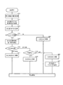
図2は、BDプレーヤ3が再生を開始するときの制御部10の動作を示すフローチャートである。制御部10は、BDの再生開始時に、HDMI受信部11を介して、BDプレーヤ3から、再生される映像の種類を取得する(S10)。映像の種類とは、たとえば、通常の映像、4K映像、3D映像などである。制御部10は、取得した映像の種類を、HDMI送信部14のCEC経由でテレビ4に通知する(S11)。この応答として、制御部10は、HDMI送信部14のCEC経由でテレビ4から映像再生のための遅延時間DVを取得する(S12)。すなわち、テレビ4は、レシーバ1から送られてきた映像信号の種類を見て必要な処理時間を判断し、その処理時間をダイナミック自動リップシンク情報として返信する。
FIG. 2 is a flowchart showing the operation of the
次に、パワードスピーカ2が接続されているか(動作しているか)を判断する(S13)。ネットワークモジュール15がパワードスピーカ2と通信している状態であれば、パワードスピーカ15が接続されていると言える。パワードスピーカ2が接続されていない場合(S13でNO)、制御部10は、信号処理部12の遅延時間である音声遅延DAを映像遅延DVと同じになるように信号処理部12に指示して(S14)、BDの再生を開始する(S25)。信号処理部12は、音声信号の処理時間に加えて必要な時間分のデータをバッファすることにより、音声遅延DAが映像遅延DVと同じになるように調整する。BD再生の開始は、BDプレーヤ2に対して映像信号の送信を開始するように指示する手順を含む。
Next, it is determined whether the
パワードスピーカ2が接続されている場合には(S13でYES)、制御部10は処理をS15に進め、ネットワークモジュール15のパワードスピーカ2との通信実績(たとえばPingの応答時間など)に基づいて配信遅延DNを決定する(S15)。配信遅延DNは、たとえば、応答時間が長いと、通信そのものに時間が掛かるうえ、配信が途切れる可能性が高くなるためバッファ量を多くしなければならないことなどを考慮して決定される。比較の結果、映像遅延DVが配信遅延DN以上であれば(S16)、制御部10は、音声遅延DAおよび配信遅延DNを映像遅延DVに同期させる(S17)。音声遅延DAの同期は、信号処理部12における音声信号のバッファ量を多くすることで調整される。配信遅延DNの同期は、音声パケットに付すタイムスタンプをその遅延時間だけ先にすることで調整される。
When the
一方、テレビ4の映像遅延DVが配信遅延DNよりも小さい場合(S16)、制御部10は、音声遅延DAを映像遅延DV,配信遅延DNのどちらに同期させるかを判断する(S18)。どちらに同期させるかは、ユーザによる設定や再生されるコンテンツの種類に応じて判断すればよい。制御部10が音声遅延DAを映像遅延DVに同期させると判断した場合(S18)、信号処理部12に対して音声遅延DAを映像遅延DVと同じするよう指示して(S19)BDの再生を開始する。なお、この場合、スピーカ16から放音される音響はテレビ4に表示される映像と同期するが、パワードスピーカ2(スピーカ23)から放音される音響は、それとは若干遅れたものとなる。
On the other hand, when the video delay DV of the television 4 is smaller than the delivery delay DN (S16), the
一方、制御部10がDSP12の遅延時間DAを配信遅延DNに同期させると判断した場合(S18)、信号処理部12に対して音声遅延DAを配信遅延DNと同じするよう指示して(S20)、BDの再生を開始する。この場合、スピーカ16、23から放音される音響は互いに同期しているが、テレビ4に表示される映像からは若干遅れたものとなる。
On the other hand, when the
なお、ある種のテレビ4は、遅延の大きいBluetoothスピーカや、本件のようなネットワーク接続されたパワードスピーカ2に映像を同期させるなどのために、映像をバッファして任意の時間遅延させることができるものがある。このようなテレビ4の場合、制御部10は、HDMI送信部14のCECを介してテレビ4に配信遅延時間DNの情報を送信し(S21)、テレビ4の映像遅延DVを配信遅延DNと同じになるように調整してもよい。
Note that a certain type of television 4 can buffer the video and delay it for an arbitrary time in order to synchronize the video with a Bluetooth speaker having a large delay or a
1 レシーバ
2 パワードスピーカ
3 BD(ブルーレイディスク)プレーヤ
4 テレビ
1
Claims (3)
前記音声信号を遅延させて出力する信号処理部と、
映像再生機器に対して前記映像信号を送信する信号出力部と、
他のオーディオ機器に前記音声信号を放音時刻を指示するタイムスタンプを付して送信する通信部と、
制御部と、
を備え、
前記制御部は、
前記信号出力部を介して、前記映像再生機器から送信した映像信号を表示するまでに必要な処理時間である映像遅延時間を取得し、
前記通信部から、前記他のオーディオ機器の前記音声信号の放音までの遅延時間である配信遅延時間を取得し、
前記映像遅延時間が配信遅延時間以上の場合、前記信号処理部の遅延時間を前記映像遅延時間と同じに設定するとともに、前記通信部が送信する音声信号に、前記映像遅延時間だけ遅延させるタイムスタンプを付す
オーディオ機器。 A signal input unit for inputting a video signal and an audio signal;
A signal processing unit that delays and outputs the audio signal;
A signal output unit for transmitting the video signal to a video playback device;
A communication unit for transmitting the audio signal to another audio device with a time stamp indicating a sound emission time; and
A control unit;
With
The controller is
Via the signal output unit, obtain a video delay time that is a processing time required to display a video signal transmitted from the video playback device,
From the communication unit, obtaining a delivery delay time that is a delay time until the sound signal of the other audio device is emitted,
When the video delay time is equal to or greater than the delivery delay time, the delay time of the signal processing unit is set to be the same as the video delay time, and the time stamp that delays the audio signal transmitted by the communication unit by the video delay time Audio equipment.
前記映像遅延時間が前記配信遅延時間よりも小さい場合、前記映像信号の種類またはユーザによる選択に応じて、前記信号処理部の遅延時間を前記映像遅延時間または前記配信遅延時間のいずれかと同じに設定し、前記通信部が送信する音声信号に、前記配信遅延時間だけ遅延させるタイムスタンプを付す
請求項1に記載のオーディオ機器。 The controller is
When the video delay time is smaller than the delivery delay time, the delay time of the signal processing unit is set to be the same as either the video delay time or the delivery delay time according to the type of the video signal or selection by the user. The audio device according to claim 1, wherein a time stamp that is delayed by the delivery delay time is attached to the audio signal transmitted by the communication unit.
前記信号処理部の遅延時間を前記配信遅延時間と同じに設定した場合、前記信号出力部を介して、前記映像再生機器に対して、前記映像遅延時間を前記配信遅延時間と同じに設定するよう指示する
請求項2に記載のオーディオ機器。 The controller is
When the delay time of the signal processing unit is set to be the same as the delivery delay time, the video delay time is set to be the same as the delivery delay time for the video playback device via the signal output unit. The audio device according to claim 2.
Priority Applications (2)
| Application Number | Priority Date | Filing Date | Title |
|---|---|---|---|
| JP2016027882A JP6720566B2 (en) | 2016-02-17 | 2016-02-17 | Audio equipment |
| PCT/JP2017/005560 WO2017141977A1 (en) | 2016-02-17 | 2017-02-15 | Audio device and control method |
Applications Claiming Priority (1)
| Application Number | Priority Date | Filing Date | Title |
|---|---|---|---|
| JP2016027882A JP6720566B2 (en) | 2016-02-17 | 2016-02-17 | Audio equipment |
Publications (2)
| Publication Number | Publication Date |
|---|---|
| JP2017147594A true JP2017147594A (en) | 2017-08-24 |
| JP6720566B2 JP6720566B2 (en) | 2020-07-08 |
Family
ID=59625962
Family Applications (1)
| Application Number | Title | Priority Date | Filing Date |
|---|---|---|---|
| JP2016027882A Active JP6720566B2 (en) | 2016-02-17 | 2016-02-17 | Audio equipment |
Country Status (2)
| Country | Link |
|---|---|
| JP (1) | JP6720566B2 (en) |
| WO (1) | WO2017141977A1 (en) |
Cited By (3)
| Publication number | Priority date | Publication date | Assignee | Title |
|---|---|---|---|---|
| WO2020024980A1 (en) * | 2018-08-01 | 2020-02-06 | 北京微播视界科技有限公司 | Data processing method and apparatus |
| WO2021020600A1 (en) * | 2019-07-26 | 2021-02-04 | 엘지전자 주식회사 | Multimedia service providing device and multimedia service providing method |
| WO2023121326A1 (en) * | 2021-12-22 | 2023-06-29 | 삼성전자주식회사 | Electronic device and control method therefor |
Families Citing this family (1)
| Publication number | Priority date | Publication date | Assignee | Title |
|---|---|---|---|---|
| CN109600564B (en) * | 2018-08-01 | 2020-06-02 | 北京微播视界科技有限公司 | Method and apparatus for determining a timestamp |
Citations (2)
| Publication number | Priority date | Publication date | Assignee | Title |
|---|---|---|---|---|
| WO2006118106A1 (en) * | 2005-04-28 | 2006-11-09 | Matsushita Electric Industrial Co., Ltd. | Lip-sync correcting device and lip-sync correcting method |
| JP2007159092A (en) * | 2005-11-11 | 2007-06-21 | Sharp Corp | Audio/video processing main unit and control method thereof, audio processing terminal device and control method thereof, audio processing main unit, audio-video processing system, audio/video processing main unit control program, audio processing terminal device control program, and recording medium in which the program is recorded |
-
2016
- 2016-02-17 JP JP2016027882A patent/JP6720566B2/en active Active
-
2017
- 2017-02-15 WO PCT/JP2017/005560 patent/WO2017141977A1/en active Application Filing
Patent Citations (2)
| Publication number | Priority date | Publication date | Assignee | Title |
|---|---|---|---|---|
| WO2006118106A1 (en) * | 2005-04-28 | 2006-11-09 | Matsushita Electric Industrial Co., Ltd. | Lip-sync correcting device and lip-sync correcting method |
| JP2007159092A (en) * | 2005-11-11 | 2007-06-21 | Sharp Corp | Audio/video processing main unit and control method thereof, audio processing terminal device and control method thereof, audio processing main unit, audio-video processing system, audio/video processing main unit control program, audio processing terminal device control program, and recording medium in which the program is recorded |
Cited By (4)
| Publication number | Priority date | Publication date | Assignee | Title |
|---|---|---|---|---|
| WO2020024980A1 (en) * | 2018-08-01 | 2020-02-06 | 北京微播视界科技有限公司 | Data processing method and apparatus |
| WO2021020600A1 (en) * | 2019-07-26 | 2021-02-04 | 엘지전자 주식회사 | Multimedia service providing device and multimedia service providing method |
| US11871069B2 (en) | 2019-07-26 | 2024-01-09 | Lg Electronics Inc. | Multimedia service providing device and multimedia service providing method |
| WO2023121326A1 (en) * | 2021-12-22 | 2023-06-29 | 삼성전자주식회사 | Electronic device and control method therefor |
Also Published As
| Publication number | Publication date |
|---|---|
| JP6720566B2 (en) | 2020-07-08 |
| WO2017141977A1 (en) | 2017-08-24 |
Similar Documents
| Publication | Publication Date | Title |
|---|---|---|
| JP6702455B2 (en) | Display device, display control method, and computer program | |
| US10992451B2 (en) | Audio and video playback system and method for playing audio data applied thereto | |
| KR100912212B1 (en) | Audiovisualav device and control method thereof | |
| US8117330B2 (en) | Information processing device for relaying streaming data | |
| EP1936990A2 (en) | Digital broadcast receiving apparatus and synchronization method | |
| JP6720566B2 (en) | Audio equipment | |
| JP2012119924A (en) | Video display apparatus, video display method, audio reproduction apparatus, audio reproduction method, and video/audio synchronous control system | |
| JP2012191524A (en) | Acoustic device and acoustic system | |
| US9886980B2 (en) | Method for synchronizing A/V streams | |
| KR101600891B1 (en) | Synchronization method and system for audio and video of a plurality terminal | |
| KR100644562B1 (en) | Apparatus for synchronizing audio/video signal and method thereof | |
| US20230016118A1 (en) | System and method to synchronize rendering of multi-channel audio to video presentation | |
| US20080211963A1 (en) | Equipment For Audio-Video Processing System | |
| JPWO2014162748A1 (en) | Receiving apparatus and receiving method | |
| US20100166382A1 (en) | Video and audio reproduction system, distribution device, and synchronization adjustment method | |
| US10209952B2 (en) | Content reproduction device, content reproduction system, and control method for a content reproduction device | |
| BR102020025848A2 (en) | DECODER EQUIPMENT WITH TWO AUDIO LINKS | |
| JP2013143706A (en) | Video audio processing device and program therefor | |
| JP2009124223A (en) | Av system | |
| KR100677162B1 (en) | AV system for adjusting audio/video rip synchronization | |
| KR100793790B1 (en) | Wireless Video System and Method of Processing a signal in the Wireless Video System | |
| JP5127992B2 (en) | Video processing apparatus, video processing method, audio reproduction apparatus, and audio reproduction method | |
| TWI587696B (en) | Method for synchronization of data display | |
| JP2011239096A (en) | Transmission apparatus | |
| JP2014143724A (en) | Video signal processing unit |
Legal Events
| Date | Code | Title | Description |
|---|---|---|---|
| A621 | Written request for application examination |
Free format text: JAPANESE INTERMEDIATE CODE: A621 Effective date: 20181220 |
|
| A131 | Notification of reasons for refusal |
Free format text: JAPANESE INTERMEDIATE CODE: A131 Effective date: 20191119 |
|
| A521 | Request for written amendment filed |
Free format text: JAPANESE INTERMEDIATE CODE: A523 Effective date: 20200120 |
|
| TRDD | Decision of grant or rejection written | ||
| A01 | Written decision to grant a patent or to grant a registration (utility model) |
Free format text: JAPANESE INTERMEDIATE CODE: A01 Effective date: 20200519 |
|
| A61 | First payment of annual fees (during grant procedure) |
Free format text: JAPANESE INTERMEDIATE CODE: A61 Effective date: 20200601 |
|
| R151 | Written notification of patent or utility model registration |
Ref document number: 6720566 Country of ref document: JP Free format text: JAPANESE INTERMEDIATE CODE: R151 |