JP2017145190A - Production of laminated glass panel - Google Patents
Production of laminated glass panel Download PDFInfo
- Publication number
- JP2017145190A JP2017145190A JP2017057576A JP2017057576A JP2017145190A JP 2017145190 A JP2017145190 A JP 2017145190A JP 2017057576 A JP2017057576 A JP 2017057576A JP 2017057576 A JP2017057576 A JP 2017057576A JP 2017145190 A JP2017145190 A JP 2017145190A
- Authority
- JP
- Japan
- Prior art keywords
- controlled cooling
- glass
- cooling
- local
- glazing
- Prior art date
- Legal status (The legal status is an assumption and is not a legal conclusion. Google has not performed a legal analysis and makes no representation as to the accuracy of the status listed.)
- Granted
Links
- 238000004519 manufacturing process Methods 0.000 title claims description 31
- 239000005340 laminated glass Substances 0.000 title description 4
- 239000011521 glass Substances 0.000 claims abstract description 150
- 239000000758 substrate Substances 0.000 claims abstract description 118
- 238000005520 cutting process Methods 0.000 claims abstract description 66
- 238000001816 cooling Methods 0.000 claims description 169
- 238000000034 method Methods 0.000 claims description 107
- 238000005452 bending Methods 0.000 claims description 56
- 239000000463 material Substances 0.000 claims description 47
- 239000011248 coating agent Substances 0.000 claims description 12
- 238000000576 coating method Methods 0.000 claims description 12
- 239000002861 polymer material Substances 0.000 claims description 10
- 230000005855 radiation Effects 0.000 claims description 10
- XLYOFNOQVPJJNP-UHFFFAOYSA-N water Substances O XLYOFNOQVPJJNP-UHFFFAOYSA-N 0.000 claims description 9
- 230000007423 decrease Effects 0.000 claims description 8
- 238000007664 blowing Methods 0.000 claims description 7
- 239000004744 fabric Substances 0.000 claims description 3
- 230000006835 compression Effects 0.000 description 31
- 238000007906 compression Methods 0.000 description 31
- 239000010410 layer Substances 0.000 description 27
- 239000002184 metal Substances 0.000 description 7
- 229920002037 poly(vinyl butyral) polymer Polymers 0.000 description 5
- 239000007921 spray Substances 0.000 description 5
- 229910003460 diamond Inorganic materials 0.000 description 4
- 239000010432 diamond Substances 0.000 description 4
- 238000005553 drilling Methods 0.000 description 4
- 239000005357 flat glass Substances 0.000 description 4
- 238000005259 measurement Methods 0.000 description 4
- 230000005484 gravity Effects 0.000 description 3
- 230000003287 optical effect Effects 0.000 description 3
- 230000002093 peripheral effect Effects 0.000 description 3
- 238000005507 spraying Methods 0.000 description 3
- 238000012546 transfer Methods 0.000 description 3
- 230000015572 biosynthetic process Effects 0.000 description 2
- 238000007872 degassing Methods 0.000 description 2
- 238000003825 pressing Methods 0.000 description 2
- 239000000047 product Substances 0.000 description 2
- 238000007493 shaping process Methods 0.000 description 2
- 230000035939 shock Effects 0.000 description 2
- 238000010561 standard procedure Methods 0.000 description 2
- 241001115479 Opheodrys Species 0.000 description 1
- 229910000831 Steel Inorganic materials 0.000 description 1
- 238000013459 approach Methods 0.000 description 1
- 238000003490 calendering Methods 0.000 description 1
- 239000003086 colorant Substances 0.000 description 1
- 239000002826 coolant Substances 0.000 description 1
- 230000007547 defect Effects 0.000 description 1
- 230000000694 effects Effects 0.000 description 1
- 239000002320 enamel (paints) Substances 0.000 description 1
- 239000000835 fiber Substances 0.000 description 1
- 239000002657 fibrous material Substances 0.000 description 1
- 239000012467 final product Substances 0.000 description 1
- 239000012210 heat-resistant fiber Substances 0.000 description 1
- 238000009434 installation Methods 0.000 description 1
- 239000011810 insulating material Substances 0.000 description 1
- 239000011229 interlayer Substances 0.000 description 1
- 239000013067 intermediate product Substances 0.000 description 1
- 239000007788 liquid Substances 0.000 description 1
- 239000012528 membrane Substances 0.000 description 1
- 238000000465 moulding Methods 0.000 description 1
- 231100000252 nontoxic Toxicity 0.000 description 1
- 230000003000 nontoxic effect Effects 0.000 description 1
- 239000011368 organic material Substances 0.000 description 1
- 229920003023 plastic Polymers 0.000 description 1
- 239000004033 plastic Substances 0.000 description 1
- 229920000642 polymer Polymers 0.000 description 1
- 238000009666 routine test Methods 0.000 description 1
- 238000007650 screen-printing Methods 0.000 description 1
- 238000007789 sealing Methods 0.000 description 1
- 239000010959 steel Substances 0.000 description 1
- 238000013519 translation Methods 0.000 description 1
Images

Classifications
-
- E—FIXED CONSTRUCTIONS
- E06—DOORS, WINDOWS, SHUTTERS, OR ROLLER BLINDS IN GENERAL; LADDERS
- E06B—FIXED OR MOVABLE CLOSURES FOR OPENINGS IN BUILDINGS, VEHICLES, FENCES OR LIKE ENCLOSURES IN GENERAL, e.g. DOORS, WINDOWS, BLINDS, GATES
- E06B3/00—Window sashes, door leaves, or like elements for closing wall or like openings; Layout of fixed or moving closures, e.g. windows in wall or like openings; Features of rigidly-mounted outer frames relating to the mounting of wing frames
- E06B3/66—Units comprising two or more parallel glass or like panes permanently secured together
- E06B3/673—Assembling the units
-
- C—CHEMISTRY; METALLURGY
- C03—GLASS; MINERAL OR SLAG WOOL
- C03C—CHEMICAL COMPOSITION OF GLASSES, GLAZES OR VITREOUS ENAMELS; SURFACE TREATMENT OF GLASS; SURFACE TREATMENT OF FIBRES OR FILAMENTS MADE FROM GLASS, MINERALS OR SLAGS; JOINING GLASS TO GLASS OR OTHER MATERIALS
- C03C27/00—Joining pieces of glass to pieces of other inorganic material; Joining glass to glass other than by fusing
- C03C27/06—Joining glass to glass by processes other than fusing
- C03C27/10—Joining glass to glass by processes other than fusing with the aid of adhesive specially adapted for that purpose
-
- B—PERFORMING OPERATIONS; TRANSPORTING
- B32—LAYERED PRODUCTS
- B32B—LAYERED PRODUCTS, i.e. PRODUCTS BUILT-UP OF STRATA OF FLAT OR NON-FLAT, e.g. CELLULAR OR HONEYCOMB, FORM
- B32B17/00—Layered products essentially comprising sheet glass, or glass, slag, or like fibres
- B32B17/06—Layered products essentially comprising sheet glass, or glass, slag, or like fibres comprising glass as the main or only constituent of a layer, next to another layer of a specific material
- B32B17/10—Layered products essentially comprising sheet glass, or glass, slag, or like fibres comprising glass as the main or only constituent of a layer, next to another layer of a specific material of synthetic resin
- B32B17/10005—Layered products essentially comprising sheet glass, or glass, slag, or like fibres comprising glass as the main or only constituent of a layer, next to another layer of a specific material of synthetic resin laminated safety glass or glazing
- B32B17/10009—Layered products essentially comprising sheet glass, or glass, slag, or like fibres comprising glass as the main or only constituent of a layer, next to another layer of a specific material of synthetic resin laminated safety glass or glazing characterized by the number, the constitution or treatment of glass sheets
- B32B17/10036—Layered products essentially comprising sheet glass, or glass, slag, or like fibres comprising glass as the main or only constituent of a layer, next to another layer of a specific material of synthetic resin laminated safety glass or glazing characterized by the number, the constitution or treatment of glass sheets comprising two outer glass sheets
-
- B—PERFORMING OPERATIONS; TRANSPORTING
- B32—LAYERED PRODUCTS
- B32B—LAYERED PRODUCTS, i.e. PRODUCTS BUILT-UP OF STRATA OF FLAT OR NON-FLAT, e.g. CELLULAR OR HONEYCOMB, FORM
- B32B17/00—Layered products essentially comprising sheet glass, or glass, slag, or like fibres
- B32B17/06—Layered products essentially comprising sheet glass, or glass, slag, or like fibres comprising glass as the main or only constituent of a layer, next to another layer of a specific material
- B32B17/10—Layered products essentially comprising sheet glass, or glass, slag, or like fibres comprising glass as the main or only constituent of a layer, next to another layer of a specific material of synthetic resin
- B32B17/10005—Layered products essentially comprising sheet glass, or glass, slag, or like fibres comprising glass as the main or only constituent of a layer, next to another layer of a specific material of synthetic resin laminated safety glass or glazing
- B32B17/10165—Functional features of the laminated safety glass or glazing
- B32B17/10293—Edge features, e.g. inserts or holes
-
- B—PERFORMING OPERATIONS; TRANSPORTING
- B32—LAYERED PRODUCTS
- B32B—LAYERED PRODUCTS, i.e. PRODUCTS BUILT-UP OF STRATA OF FLAT OR NON-FLAT, e.g. CELLULAR OR HONEYCOMB, FORM
- B32B17/00—Layered products essentially comprising sheet glass, or glass, slag, or like fibres
- B32B17/06—Layered products essentially comprising sheet glass, or glass, slag, or like fibres comprising glass as the main or only constituent of a layer, next to another layer of a specific material
- B32B17/10—Layered products essentially comprising sheet glass, or glass, slag, or like fibres comprising glass as the main or only constituent of a layer, next to another layer of a specific material of synthetic resin
- B32B17/10005—Layered products essentially comprising sheet glass, or glass, slag, or like fibres comprising glass as the main or only constituent of a layer, next to another layer of a specific material of synthetic resin laminated safety glass or glazing
- B32B17/1055—Layered products essentially comprising sheet glass, or glass, slag, or like fibres comprising glass as the main or only constituent of a layer, next to another layer of a specific material of synthetic resin laminated safety glass or glazing characterized by the resin layer, i.e. interlayer
- B32B17/10761—Layered products essentially comprising sheet glass, or glass, slag, or like fibres comprising glass as the main or only constituent of a layer, next to another layer of a specific material of synthetic resin laminated safety glass or glazing characterized by the resin layer, i.e. interlayer containing vinyl acetal
-
- B—PERFORMING OPERATIONS; TRANSPORTING
- B32—LAYERED PRODUCTS
- B32B—LAYERED PRODUCTS, i.e. PRODUCTS BUILT-UP OF STRATA OF FLAT OR NON-FLAT, e.g. CELLULAR OR HONEYCOMB, FORM
- B32B17/00—Layered products essentially comprising sheet glass, or glass, slag, or like fibres
- B32B17/06—Layered products essentially comprising sheet glass, or glass, slag, or like fibres comprising glass as the main or only constituent of a layer, next to another layer of a specific material
- B32B17/10—Layered products essentially comprising sheet glass, or glass, slag, or like fibres comprising glass as the main or only constituent of a layer, next to another layer of a specific material of synthetic resin
- B32B17/10005—Layered products essentially comprising sheet glass, or glass, slag, or like fibres comprising glass as the main or only constituent of a layer, next to another layer of a specific material of synthetic resin laminated safety glass or glazing
- B32B17/10807—Making laminated safety glass or glazing; Apparatus therefor
- B32B17/10981—Pre-treatment of the layers
-
- B—PERFORMING OPERATIONS; TRANSPORTING
- B32—LAYERED PRODUCTS
- B32B—LAYERED PRODUCTS, i.e. PRODUCTS BUILT-UP OF STRATA OF FLAT OR NON-FLAT, e.g. CELLULAR OR HONEYCOMB, FORM
- B32B17/00—Layered products essentially comprising sheet glass, or glass, slag, or like fibres
- B32B17/06—Layered products essentially comprising sheet glass, or glass, slag, or like fibres comprising glass as the main or only constituent of a layer, next to another layer of a specific material
- B32B17/10—Layered products essentially comprising sheet glass, or glass, slag, or like fibres comprising glass as the main or only constituent of a layer, next to another layer of a specific material of synthetic resin
- B32B17/10005—Layered products essentially comprising sheet glass, or glass, slag, or like fibres comprising glass as the main or only constituent of a layer, next to another layer of a specific material of synthetic resin laminated safety glass or glazing
- B32B17/10807—Making laminated safety glass or glazing; Apparatus therefor
- B32B17/1099—After-treatment of the layered product, e.g. cooling
-
- B—PERFORMING OPERATIONS; TRANSPORTING
- B60—VEHICLES IN GENERAL
- B60J—WINDOWS, WINDSCREENS, NON-FIXED ROOFS, DOORS, OR SIMILAR DEVICES FOR VEHICLES; REMOVABLE EXTERNAL PROTECTIVE COVERINGS SPECIALLY ADAPTED FOR VEHICLES
- B60J1/00—Windows; Windscreens; Accessories therefor
- B60J1/001—Double glazing for vehicles
-
- B—PERFORMING OPERATIONS; TRANSPORTING
- B60—VEHICLES IN GENERAL
- B60J—WINDOWS, WINDSCREENS, NON-FIXED ROOFS, DOORS, OR SIMILAR DEVICES FOR VEHICLES; REMOVABLE EXTERNAL PROTECTIVE COVERINGS SPECIALLY ADAPTED FOR VEHICLES
- B60J7/00—Non-fixed roofs; Roofs with movable panels, e.g. rotary sunroofs
- B60J7/02—Non-fixed roofs; Roofs with movable panels, e.g. rotary sunroofs of sliding type, e.g. comprising guide shoes
- B60J7/04—Non-fixed roofs; Roofs with movable panels, e.g. rotary sunroofs of sliding type, e.g. comprising guide shoes with rigid plate-like element or elements, e.g. open roofs with harmonica-type folding rigid panels
- B60J7/043—Sunroofs e.g. sliding above the roof
-
- C—CHEMISTRY; METALLURGY
- C03—GLASS; MINERAL OR SLAG WOOL
- C03B—MANUFACTURE, SHAPING, OR SUPPLEMENTARY PROCESSES
- C03B23/00—Re-forming shaped glass
- C03B23/02—Re-forming glass sheets
- C03B23/023—Re-forming glass sheets by bending
-
- C—CHEMISTRY; METALLURGY
- C03—GLASS; MINERAL OR SLAG WOOL
- C03B—MANUFACTURE, SHAPING, OR SUPPLEMENTARY PROCESSES
- C03B23/00—Re-forming shaped glass
- C03B23/02—Re-forming glass sheets
- C03B23/023—Re-forming glass sheets by bending
- C03B23/0235—Re-forming glass sheets by bending involving applying local or additional heating, cooling or insulating means
-
- C—CHEMISTRY; METALLURGY
- C03—GLASS; MINERAL OR SLAG WOOL
- C03B—MANUFACTURE, SHAPING, OR SUPPLEMENTARY PROCESSES
- C03B23/00—Re-forming shaped glass
- C03B23/02—Re-forming glass sheets
- C03B23/023—Re-forming glass sheets by bending
- C03B23/025—Re-forming glass sheets by bending by gravity
- C03B23/0252—Re-forming glass sheets by bending by gravity by gravity only, e.g. sagging
-
- C—CHEMISTRY; METALLURGY
- C03—GLASS; MINERAL OR SLAG WOOL
- C03B—MANUFACTURE, SHAPING, OR SUPPLEMENTARY PROCESSES
- C03B23/00—Re-forming shaped glass
- C03B23/02—Re-forming glass sheets
- C03B23/023—Re-forming glass sheets by bending
- C03B23/025—Re-forming glass sheets by bending by gravity
- C03B23/0258—Gravity bending involving applying local or additional heating, cooling or insulating means
-
- C—CHEMISTRY; METALLURGY
- C03—GLASS; MINERAL OR SLAG WOOL
- C03B—MANUFACTURE, SHAPING, OR SUPPLEMENTARY PROCESSES
- C03B23/00—Re-forming shaped glass
- C03B23/02—Re-forming glass sheets
- C03B23/023—Re-forming glass sheets by bending
- C03B23/03—Re-forming glass sheets by bending by press-bending between shaping moulds
-
- C—CHEMISTRY; METALLURGY
- C03—GLASS; MINERAL OR SLAG WOOL
- C03B—MANUFACTURE, SHAPING, OR SUPPLEMENTARY PROCESSES
- C03B23/00—Re-forming shaped glass
- C03B23/02—Re-forming glass sheets
- C03B23/023—Re-forming glass sheets by bending
- C03B23/035—Re-forming glass sheets by bending using a gas cushion or by changing gas pressure, e.g. by applying vacuum or blowing for supporting the glass while bending
- C03B23/0352—Re-forming glass sheets by bending using a gas cushion or by changing gas pressure, e.g. by applying vacuum or blowing for supporting the glass while bending by suction or blowing out for providing the deformation force to bend the glass sheet
-
- C—CHEMISTRY; METALLURGY
- C03—GLASS; MINERAL OR SLAG WOOL
- C03B—MANUFACTURE, SHAPING, OR SUPPLEMENTARY PROCESSES
- C03B27/00—Tempering or quenching glass products
- C03B27/004—Tempering or quenching glass products by bringing the hot glass product in contact with a solid cooling surface, e.g. sand grains
-
- C—CHEMISTRY; METALLURGY
- C03—GLASS; MINERAL OR SLAG WOOL
- C03B—MANUFACTURE, SHAPING, OR SUPPLEMENTARY PROCESSES
- C03B27/00—Tempering or quenching glass products
- C03B27/04—Tempering or quenching glass products using gas
- C03B27/0404—Nozzles, blow heads, blowing units or their arrangements, specially adapted for flat or bent glass sheets
-
- C—CHEMISTRY; METALLURGY
- C03—GLASS; MINERAL OR SLAG WOOL
- C03B—MANUFACTURE, SHAPING, OR SUPPLEMENTARY PROCESSES
- C03B27/00—Tempering or quenching glass products
- C03B27/04—Tempering or quenching glass products using gas
- C03B27/0413—Stresses, e.g. patterns, values or formulae for flat or bent glass sheets
-
- C—CHEMISTRY; METALLURGY
- C03—GLASS; MINERAL OR SLAG WOOL
- C03B—MANUFACTURE, SHAPING, OR SUPPLEMENTARY PROCESSES
- C03B27/00—Tempering or quenching glass products
- C03B27/04—Tempering or quenching glass products using gas
- C03B27/044—Tempering or quenching glass products using gas for flat or bent glass sheets being in a horizontal position
- C03B27/0442—Tempering or quenching glass products using gas for flat or bent glass sheets being in a horizontal position for bent glass sheets
-
- C—CHEMISTRY; METALLURGY
- C03—GLASS; MINERAL OR SLAG WOOL
- C03B—MANUFACTURE, SHAPING, OR SUPPLEMENTARY PROCESSES
- C03B33/00—Severing cooled glass
- C03B33/02—Cutting or splitting sheet glass or ribbons; Apparatus or machines therefor
-
- C—CHEMISTRY; METALLURGY
- C03—GLASS; MINERAL OR SLAG WOOL
- C03B—MANUFACTURE, SHAPING, OR SUPPLEMENTARY PROCESSES
- C03B33/00—Severing cooled glass
- C03B33/07—Cutting armoured, multi-layered, coated or laminated, glass products
- C03B33/076—Laminated glass comprising interlayers
- C03B33/078—Polymeric interlayers
-
- C—CHEMISTRY; METALLURGY
- C03—GLASS; MINERAL OR SLAG WOOL
- C03B—MANUFACTURE, SHAPING, OR SUPPLEMENTARY PROCESSES
- C03B33/00—Severing cooled glass
- C03B33/09—Severing cooled glass by thermal shock
-
- B—PERFORMING OPERATIONS; TRANSPORTING
- B32—LAYERED PRODUCTS
- B32B—LAYERED PRODUCTS, i.e. PRODUCTS BUILT-UP OF STRATA OF FLAT OR NON-FLAT, e.g. CELLULAR OR HONEYCOMB, FORM
- B32B2605/00—Vehicles
- B32B2605/006—Transparent parts other than made from inorganic glass, e.g. polycarbonate glazings
-
- Y—GENERAL TAGGING OF NEW TECHNOLOGICAL DEVELOPMENTS; GENERAL TAGGING OF CROSS-SECTIONAL TECHNOLOGIES SPANNING OVER SEVERAL SECTIONS OF THE IPC; TECHNICAL SUBJECTS COVERED BY FORMER USPC CROSS-REFERENCE ART COLLECTIONS [XRACs] AND DIGESTS
- Y10—TECHNICAL SUBJECTS COVERED BY FORMER USPC
- Y10T—TECHNICAL SUBJECTS COVERED BY FORMER US CLASSIFICATION
- Y10T29/00—Metal working
- Y10T29/49—Method of mechanical manufacture
- Y10T29/49826—Assembling or joining
-
- Y—GENERAL TAGGING OF NEW TECHNOLOGICAL DEVELOPMENTS; GENERAL TAGGING OF CROSS-SECTIONAL TECHNOLOGIES SPANNING OVER SEVERAL SECTIONS OF THE IPC; TECHNICAL SUBJECTS COVERED BY FORMER USPC CROSS-REFERENCE ART COLLECTIONS [XRACs] AND DIGESTS
- Y10—TECHNICAL SUBJECTS COVERED BY FORMER USPC
- Y10T—TECHNICAL SUBJECTS COVERED BY FORMER US CLASSIFICATION
- Y10T428/00—Stock material or miscellaneous articles
- Y10T428/24—Structurally defined web or sheet [e.g., overall dimension, etc.]
- Y10T428/24273—Structurally defined web or sheet [e.g., overall dimension, etc.] including aperture
- Y10T428/24322—Composite web or sheet
-
- Y—GENERAL TAGGING OF NEW TECHNOLOGICAL DEVELOPMENTS; GENERAL TAGGING OF CROSS-SECTIONAL TECHNOLOGIES SPANNING OVER SEVERAL SECTIONS OF THE IPC; TECHNICAL SUBJECTS COVERED BY FORMER USPC CROSS-REFERENCE ART COLLECTIONS [XRACs] AND DIGESTS
- Y10—TECHNICAL SUBJECTS COVERED BY FORMER USPC
- Y10T—TECHNICAL SUBJECTS COVERED BY FORMER US CLASSIFICATION
- Y10T428/00—Stock material or miscellaneous articles
- Y10T428/24—Structurally defined web or sheet [e.g., overall dimension, etc.]
- Y10T428/24479—Structurally defined web or sheet [e.g., overall dimension, etc.] including variation in thickness
- Y10T428/24612—Composite web or sheet
-
- Y—GENERAL TAGGING OF NEW TECHNOLOGICAL DEVELOPMENTS; GENERAL TAGGING OF CROSS-SECTIONAL TECHNOLOGIES SPANNING OVER SEVERAL SECTIONS OF THE IPC; TECHNICAL SUBJECTS COVERED BY FORMER USPC CROSS-REFERENCE ART COLLECTIONS [XRACs] AND DIGESTS
- Y10—TECHNICAL SUBJECTS COVERED BY FORMER USPC
- Y10T—TECHNICAL SUBJECTS COVERED BY FORMER US CLASSIFICATION
- Y10T428/00—Stock material or miscellaneous articles
- Y10T428/24—Structurally defined web or sheet [e.g., overall dimension, etc.]
- Y10T428/24628—Nonplanar uniform thickness material
Landscapes
- Chemical & Material Sciences (AREA)
- Engineering & Computer Science (AREA)
- Materials Engineering (AREA)
- Organic Chemistry (AREA)
- Physics & Mathematics (AREA)
- Thermal Sciences (AREA)
- Mechanical Engineering (AREA)
- Mathematical Physics (AREA)
- Civil Engineering (AREA)
- Structural Engineering (AREA)
- Ceramic Engineering (AREA)
- Life Sciences & Earth Sciences (AREA)
- Chemical Kinetics & Catalysis (AREA)
- General Chemical & Material Sciences (AREA)
- Geochemistry & Mineralogy (AREA)
- Joining Of Glass To Other Materials (AREA)
- Laminated Bodies (AREA)
- Re-Forming, After-Treatment, Cutting And Transporting Of Glass Products (AREA)
Abstract
Description
本発明は、積層グレージングの製造方法であって、ガラス基材とポリマー材料タイプの中間層との集成後にそれを切断することを含む方法に関する。この切断は、積層体の厚さ全体を通して行われ、特に、端部が残留圧縮応力を有する、例えば孔やノッチなどの、一部を切り取った部分を少なくとも1つ形成するために行うことができる。この切断はまた、グレージングの一方の端部から他方に至るまで行ってもよい。 The present invention relates to a method for producing laminated glazing comprising cutting a glass substrate and a polymeric material type intermediate layer after assembly. This cutting is performed through the entire thickness of the laminate, and in particular, can be performed to form at least one portion, such as a hole or notch, where the end portion has residual compressive stress, such as a hole or notch. . This cutting may also be performed from one end of the glazing to the other.
グレージングは、その使用中に、特にその取り扱い中に、破損を防ぐために耐えなくてはならない熱応力又は機械的応力にさらされる。例えば、車両のフロントガラスは、手作業によるのであろうとロボットによるのであろうと車体に搭載する際に、それらの周縁部が機械的な力にさらされる。 Glazing is subjected to thermal or mechanical stress that it must withstand to prevent breakage during its use, particularly during its handling. For example, when a vehicle windshield is mounted on a vehicle body, whether by hand or by a robot, its peripheral edge is exposed to mechanical force.
この機械的応力に加えて、グレージングはフロントガラスの除氷のサイクル中に熱に由来する応力にさらされる。 In addition to this mechanical stress, glazing is exposed to heat-derived stress during the windshield deicing cycle.
熱又は機械的作用に由来する端部におけるこれらの応力は、特にグレージングの端部において、破損する危険の原因となる。グレージングの良好な機械的強度を保証するために、グレージングの製造中に端部に圧縮応力を生じさせる。これらの端部の応力は知られているものであり、自動車製造業者の仕様書で規定されている。 These stresses at the edges resulting from heat or mechanical action cause a risk of breakage, especially at the edges of the glazing. In order to ensure good mechanical strength of the glazing, a compressive stress is created at the edges during the production of the glazing. These end stresses are known and are specified in the specifications of the car manufacturer.
グレージングの圧縮応力を有する端部に加えて、一部分を切り取った部分の周縁部にも圧縮応力が生じさせられる。 In addition to the end portion having the compressive stress of glazing, a compressive stress is also generated in the peripheral portion of the part cut out.
実際のところ、グレージングの一部を切り取った部分は、例えばグレージングの端部との間隔をあけて厚み方向に作られた孔内に固定されるアンテナなどの、付属の機能性構成部品を受け入れるように設計される。一部を切り取ったこれらの部分は、機械的応力に耐える上で2つの問題を生じさせ、すなわち、くり抜き部分がグレージングの使用中に荷重に耐えなくてはならなくなる端部を生じさせ、且つくり抜き部分が材料の局部的な除去(孔、ノッチ)のために応力の集中ゾーンを生じさせる。これに関連して、グレージングは、その孔又はノッチの端部が、アンテナを取り付けることによる恒久的なものであり、また、特に車両が何らかの低いものをくぐる場合などにアンテナに衝撃がかかる際に生じる一時的なものである、様々な機械的応力にさらされる。同様に、後部ドアのグレージングの場合で孔がワイパーを受け入れることを目的としたものである場合、孔の端部は後部ドアの閉鎖に耐えなければならない。 In fact, the cut away portion of the glazing is intended to accept an attached functional component, such as an antenna that is fixed in a hole in the thickness direction spaced from the end of the glazing. Designed to. These parts, which have been cut off, create two problems in resisting mechanical stress, i.e., the cut out part creates an end that must withstand the load during glazing use, and the cut out part. The part creates a stress concentration zone due to local removal of material (holes, notches). In this context, glazing is the permanent end of the hole or notch due to the mounting of the antenna, and when the vehicle is impacted, especially when the vehicle passes through something low. It is exposed to various mechanical stresses that are temporary. Similarly, in the case of rear door glazing, if the hole is intended to receive a wiper, the end of the hole must withstand the closure of the rear door.
ガラス製品における応力は、ガラスがその純然たる弾性的性質を失ってわずかに可塑性となり、粘弾性液体タイプとなり始める温度でそれを加熱すると生じる。冷却中に、サンプルの初期の熱的不均一性及び/又は冷却それ自体の不均一性に応じて、一部のゾーンが他のものより先に凝固する。熱膨張のために、恒久的な圧縮応力と引張応力が冷却中のサンプル内に現れる。定性的には、ガラスが最初に凝固する部分は圧縮応力が集中する部分に相当し、それに対しガラスが遅れて凝固する部分は引張応力のゾーンに集中する。本願に記載される端部応力は、材料の任意の箇所Mで、所定の方向についてこの方向に沿ってこの箇所において応力が加えられる領域の平均として定義することができる膜応力であり、その平均はサンプルの厚さ全体で取られる。サンプルの端部では、端部に平行な膜応力の成分のみが充当し、垂直成分はゼロの値を有する。従って、サンプルの端部に沿って且つその厚さを貫いて平均応力の測定を可能にするいずれの方法も適切なものである。それらの端部応力を測定するための方法は、光弾性の技術を利用する。下記に示すASTM標準規格に記載された2つの方法が、端部応力の値の測定を可能にする。
・ASTM C1279−2009−01の手順Bに記載された、バビネ補償板を使用する方法。
・例えば英国PrestonのSharples Stress Engineers社により販売されるSharplesモデルS−67などの市販の装置を用い、Jessop−FriedelのSenarmont補償板を使用して行われる測定。この測定の原理はASTM標準規格F218−2005−01に記載されている。
Stress in a glass product occurs when the glass loses its purely elastic properties and becomes slightly plastic and heats it at a temperature that begins to become a viscoelastic liquid type. During cooling, some zones solidify before others, depending on the initial thermal non-uniformity of the sample and / or the non-uniformity of the cooling itself. Due to thermal expansion, permanent compressive and tensile stresses appear in the cooling sample. Qualitatively, the portion where the glass solidifies first corresponds to the portion where the compressive stress is concentrated, whereas the portion where the glass solidifies later is concentrated in the zone of tensile stress. The end stress described in this application is a film stress that can be defined as the average of the area where stress is applied at this location along this direction for a given direction at any location M of the material. Is taken across the thickness of the sample. At the end of the sample, only the component of the membrane stress parallel to the end is applied and the vertical component has a value of zero. Thus, any method that allows measurement of the average stress along the edge of the sample and through its thickness is suitable. The method for measuring these end stresses utilizes photoelastic techniques. Two methods described in the ASTM standard shown below allow measurement of end stress values.
A method using a Babinet compensator, as described in Procedure B of ASTM C1279-2009-01.
Measurements made using a commercially available instrument such as the Sharples model S-67 sold by Sharps Stress Engineers of Preston, UK, and using a Jessop-Friedel Sensalmont compensator. The principle of this measurement is described in ASTM standard F218-2005-01.
本願に関しては、圧縮応力の値はASTM標準規格F218−2005−01に記載された方法により測定される。 For the present application, the value of compressive stress is measured by the method described in ASTM standard F218-2005-01.
一般に、圧縮応力の値は、1つの端部から0.1mmと2mmの間で、好ましくは1つの端部から0.5mmと1mmの間で測定される。圧縮応力の局所ゾーンが後に開口部を作る可能性を許容するゾーンである限りにおいて、それが開口部を取り囲まない場合には、開口部を開けてから前述ように開口部の端部からの距離で応力を測定して、応力の値を測定することができる。 In general, the value of compressive stress is measured between 0.1 mm and 2 mm from one end, preferably between 0.5 mm and 1 mm from one end. As long as the local zone of compressive stress is a zone that allows the possibility of creating an opening later, if it does not surround the opening, the distance from the edge of the opening as described above after opening the opening The stress value can be measured by measuring the stress.
車体向けの積層グレージングであってそれ用の特定の曲面を有するものを製造するための既知の方法であり、このグレージングの一部を切り取った部分の端部に圧縮応力を生じさせる方法は、
・当該一部を切り取る部分が位置する所望の部位で2枚の平らなガラス板に、互いどうし独立して孔を開け、
・2枚のガラス板を重ね合わせて(但しこの段階ではポリマーの中間層はなしで)それらを一緒にし、曲げ加工温度で重力によるそれらの曲げ加工を行い(ガラスは高温であり、すなわち曲げ加工工程は曲面を与えるために、従ってグレージングに最終的な三次元形状を与えるために用いられることが思い出される)、
・圧縮応力を生じさせるグレージング全体の全般的な制御された冷却を行い、
・もう一度重ね合わせた2枚の板の間にポリマー材料(一般には多くの場合PVBと呼ばれるポリビニルブチラールタイプの)を配置し、脱気を行い、すなわちガラス板と中間層との間に捕捉された空気を排除し、そしてそれらをオートクレーブで集成し、
・ガラスの2つの孔のところのPVBを切り取って孔を完成する(あるいは、集成前のPVBシートに孔を設けておくことも可能である)、
というものである。
It is a known method for manufacturing a laminated glazing for a vehicle body having a specific curved surface for the same, and a method for generating a compressive stress at the end of a portion where a part of the glazing is cut off,
・ In the desired part where the part to be cut out is located, the two flat glass plates are perforated independently of each other,
• Overlap two glass plates (but without the polymer interlayer at this stage) and perform their bending by gravity at the bending temperature (the glass is hot, ie the bending process) Is used to give a curved surface and thus give the final three-dimensional shape to glazing),
Provides general controlled cooling of the entire glazing that causes compressive stress,
Place a polymer material (generally of the polyvinyl butyral type often called PVB) between the two plates that have been layered again and degas, i.e. trapped air between the glass plate and the intermediate layer Eliminate, and assemble them in an autoclave,
-Cut the PVB at the two holes in the glass to complete the hole (or it is possible to have holes in the PVB sheet before assembly)
That's it.
しかし、この方法は、
・2つの別の工程によって2枚のそれぞれのガラス板に独立して孔を開けるにもかかわらず、その後2枚のガラス板を一緒にするときに2つの孔の良好な同心度を確保することが望ましいこと、
・これらの孔の同心度は、制御された冷却工程に先立つ曲げ加工工程の際にも完全でなければならず、そうでないと各孔の特定の周縁部が制限を受けて、冷却がより遅くなり、実質的に小さな圧縮応力を生じさせる。しかし、この完全な配置の仕方は、特に一方のガラス板の寸法が積層製品のための他方の板のそれよりも概してわずかに大きい場合に、より一層敏感であって、重ね合わせの精度に依存し、ガラス板を曲げ加工ツールの上に配置しそれらを炉へ搬送する間に互いに対する関係を維持することに依存すること、
・使用する方法に依存して脱気を行う間に様々な面倒な事態が生じかねず、特に、集成をカレンダリングにより行う場合、ガラス板を中間層とともに機械的に且つ直接プレスすると孔の周囲に応力が発生する。後者が不均一な圧縮応力ゾーンを有する場合、グレージングの破損が起こりかねない。ガラス板とPVBシートとの間で真空引き(グリーンスネーク法(周縁部をシールして真空引きする)又は真空バッグ法による)を行う別の脱気方法は、板の孔が正確な真空引きを可能にしないため、実施するのが困難であること、
・事前に孔を開けたガラスの曲げ加工は反射光に光学的欠陥(孔の周囲でのわずかなひずみ)を生じさせるという事実、
を克服するのにある種の難がある。
But this method
-To ensure good concentricity of the two holes when the two glass plates are put together after the two glass plates are independently drilled in two separate steps. Is desirable,
The concentricity of these holes must also be complete during the bending process prior to the controlled cooling process, otherwise the specific perimeter of each hole will be limited and cooling will be slower. Resulting in a substantially small compressive stress. However, this complete arrangement is more sensitive and depends on the accuracy of the overlay, especially when the dimensions of one glass plate are generally slightly larger than those of the other plate for laminated products. Relying on maintaining the relationship to each other while placing the glass sheets on the bending tool and transporting them to the furnace,
Depending on the method used, various troublesome situations may occur during deaeration, especially when the assembly is carried out by calendering, if the glass plate is mechanically and directly pressed together with the intermediate layer, the area around the hole Stress is generated. If the latter has a non-uniform compressive stress zone, glazing failure can occur. Another degassing method in which vacuuming is performed between the glass plate and the PVB sheet (by the green snake method (sealing the periphery and vacuuming) or the vacuum bag method) Is difficult to implement because it does not allow
The fact that pre-perforated glass bending causes optical defects (slight distortion around the hole) in the reflected light,
There are certain difficulties to overcome.
別の製造方法は、曲げ加工操作を板ごとに行い、上述のような重ねた板で同時には行わず、後者の方法に関連した欠点を解消するものである。しかし、このガラス板の単独の曲げ加工には、
・2枚のガラス板の周辺部にエナメル塗装を施さなくてはならない、
・2枚のガラス板の厚み又は色が異なる場合、それらの成形作業は完全に同一にはならず、これら2枚の板の信頼性のある強固な集成をすることが困難である、
・特にノッチタイプの切り欠きのあるグレージングについて、複雑な部品を集成するのが難しい、
といった特定の制限がある。
Another manufacturing method is to perform the bending operation on a plate-by-plate basis and not simultaneously with stacked plates as described above, eliminating the disadvantages associated with the latter method. However, for the independent bending of this glass plate,
・ Enamel coating must be applied to the periphery of the two glass plates.
When the thickness or color of the two glass plates are different, their molding operations are not completely the same, and it is difficult to make a reliable and strong assembly of these two plates.
・ It is difficult to assemble complex parts, especially for notched glazings with notches.
There are certain restrictions.
グレージングの適合したくり抜き部分に固定された部品を含む積層グレージングを製造するための別の解決策も開発されている。例えば、米国特許第4124367号明細書では、部品をくり抜き部分に固定する(ねじ込み又は接着で)際にグレージングを破損の危険にさらすガラス板のうちの一方のもので低下される端部の圧縮応力をくり抜き部分が有する積層グレージングを製造する危険を克服するために、単一のガラス板についてのみくり抜き部分の端部に圧縮応力を生じさせることが提案されており、このガラス板は更に、他方の関係するガラス板のものよりも寸法が小さい孔を有する。結果として、部品は単一のガラス板、すなわち孔がより小さくて制御された端部の圧縮応力を備えたもののみに固定される。 Other solutions have also been developed to produce laminated glazings that include parts secured to glazing-matched cut-out portions. For example, in U.S. Pat. No. 4,124,367, the compressive stress at the edge is reduced by one of the glass plates that exposes the glazing to a risk of breakage when the part is secured to the cut-out portion (by screwing or bonding). In order to overcome the risk of producing a laminated glazing having a hollowed portion, it has been proposed to generate a compressive stress at the end of the hollowed portion only for a single glass plate, It has holes that are smaller in size than those of the related glass plates. As a result, the part is secured only to a single glass plate, i.e., one with a smaller hole and controlled end compressive stress.
それでもやはり、最終製品は、部品が単一のガラス板に取り付けられているだけなので、機械的応力に対してそれほど強固ではない。 Nevertheless, the final product is not very robust against mechanical stress, as the parts are only attached to a single glass plate.
本発明の目的は、特に、ガラス基材を積層品として集成後に少なくとも1つの切り取られた端部を、厚みの全体にわたって備えた積層グレージングを製造するための方法を提案することである。この切り取られた端部は、特に、孔又はノッチの形を有することができる。この方法は、孔又はノッチを備えた積層グレージングのための既存の方法に対して簡素化されている。それは、積層グレージングに集成された全てのガラス基材について、切り取られた端部に沿って均一で十分な強度を持つ切り取られた端部の圧縮応力を保証する。 The object of the present invention is in particular to propose a method for producing a laminated glazing with at least one cut-out edge over its entire thickness after assembling a glass substrate as a laminate. This cut off end can in particular have the shape of a hole or notch. This method is simplified over existing methods for laminated glazing with holes or notches. It guarantees the compressive stress of the cut edge with uniform and sufficient strength along the cut edge for all glass substrates assembled in laminated glazing.
本発明によれば、積層グレージングにおける切り取られた部分は、その厚みの全体を貫通する孔又はノッチである。孔(又は開口部)は、積層グレージングの主面内でそれ自体が完全に閉じた輪郭を有する。ノッチは、グレージングの主面の内側に向かって切り取られた部分を形成するため、グレージング外縁の不連続部を構成する。それは、ある意味で、グレージングの端部における開放の孔である。 According to the present invention, the cut-out portion in the laminated glazing is a hole or notch that penetrates the entire thickness. The hole (or opening) has a completely closed profile within the main surface of the laminated glazing. The notch forms a discontinuous portion of the outer edge of the glazing because it forms a portion cut toward the inside of the main surface of the glazing. It is, in a sense, an open hole at the end of the glazing.
本発明はまた、積層グレージングに含まれ集成後に切断しなければならないガラス基材が特定の局所的な冷却を受けたならば直ぐに、その集成後の特定の線に沿って積層グレージングを切断する(必ずしも実際に孔又はノッチを作製することなしに)ことも可能にする。この場合、積層集成体の切断は互いどうし分離したいくつかの部分をもたらすことになってもよく、それにもかかわらず、これらの部分のおのおのは周辺部全体を強固とするのに必要な端部応力を有する。この場合の利点は、(本発明により切断された)端部が互いに完全に一致したいろいろな部分を得ることができること、そしてそれらの一般的形状に関して、それらのいろいろな部分を本発明により切断した端部を介して一緒にしたときに、それらの部分のうちの1つのものの曲線が必然的に別の部分に完全につながることである。 The present invention also cuts the laminate glazing along a specific line after assembly as soon as the glass substrate that is included in the laminate glazing and that must be cut after assembly undergoes a specific local cooling ( (Without necessarily actually making holes or notches). In this case, the cutting of the laminated assembly may result in several parts separated from each other, nonetheless, each of these parts is the end necessary to harden the entire periphery. Has stress. The advantage in this case is that it is possible to obtain different parts whose ends (cut according to the invention) are perfectly coincident with each other, and with respect to their general shape, these different parts have been cut according to the invention When brought together through an end, the curve of one of those parts necessarily leads to another part completely.
本発明によれば、少なくとも2つのガラス基材と基材間に配置されるポリマー材料製の少なくとも1つの中間層とを含む積層グレージングを製造するための方法であり、基材の曲げ加工、基材の制御された冷却、基材と中間層との集成を含む方法は、次の工程、すなわち、
・基材を曲げ加工する工程、
・次に基材の制御された冷却を行う工程、
・次に基材と中間層とを含む積層集成体を形成する工程、
・次に積層集成体をその主面のうちの1つにおける線(複数の孔がある場合、この線は複数の部分にあるという事実をカバーする)に沿ってその厚み全体を通して切断する工程、
をこの順番に含み、上記の制御された冷却は、全体的な制御された冷却と、上記の切断線を含むゾーンの局所的な制御された冷却とを含み、局所的な制御された冷却の方が全体的な制御された冷却よりも速いことを特徴とする。
According to the present invention, there is provided a method for producing a laminated glazing comprising at least two glass substrates and at least one intermediate layer made of a polymer material disposed between the substrates. The method comprising controlled cooling of the material, assembly of the substrate and the intermediate layer comprises the following steps:
・ Bending process of base material,
-Next, controlled cooling of the substrate,
-Next, forming a laminated assembly including a base material and an intermediate layer,
Cutting the laminated assembly through its thickness along a line in one of its major faces (if there are multiple holes, covering the fact that this line is in multiple parts);
In this order, the controlled cooling includes global controlled cooling and local controlled cooling of the zone containing the cutting line, and includes local controlled cooling. It is characterized by being faster than the overall controlled cooling.
「ガラス基材」という表現は、1以上の層(例えば反射防止層、日射制御層、摩耗防止層など)で覆われていてもよく覆われていなくてもよい個別のガラス板を意味する。ガラス板は2つの主面を含み、ガラス基材についても同じことが言える。「積層集成体」という表現は、それが自動車に取り付けられる切断後のグレージングである場合、本発明による切断前の最終的な積層グレージングを意味することもできる。 The expression “glass substrate” means an individual glass plate that may or may not be covered with one or more layers (eg, antireflection layer, solar control layer, antiwear layer, etc.). The glass plate includes two main surfaces, and the same is true for the glass substrate. The expression “laminated assembly” can also mean the final laminated glazing before cutting according to the invention, if it is a post-cut glazing attached to an automobile.
この出願においては、ガラス基材に適用される次の2つのタイプの冷却が区別される。
a)基材の外縁における十分な機械的強度を得るために基材の外縁に圧縮応力を生じさせるのを可能にする「全体的な制御された冷却」。この冷却は、グレージングの全体に全般的に適用される。このタイプの全体的冷却は当業者によく知られている。
b)本発明によって、曲げ加工後のガラスの切断を可能にし、更にその後切断した線の端部に圧縮応力を存在させることになる圧縮応力を生じさせるために、「局所的な制御された冷却」が適用される。この局所的な制御された冷却は全体的な冷却よりも速い。
In this application, the following two types of cooling applied to glass substrates are distinguished:
a) "Overall controlled cooling" that allows compressive stress to be generated at the outer edge of the substrate in order to obtain sufficient mechanical strength at the outer edge of the substrate. This cooling is generally applied throughout the glazing. This type of overall cooling is well known to those skilled in the art.
b) According to the present invention, a "local controlled cooling" is used to enable the cutting of the glass after bending and to generate a compressive stress that will then cause a compressive stress to be present at the end of the cut line. "Is applied. This local controlled cooling is faster than the overall cooling.
こうして、本発明の方法は、従来技術の方法に対して、特に次の利点を提供する。
・それは切断(又は孔あけ)を、ガラス基材のおのおのに対する曲げ加工前の2つの切断作業に代わる、2つのガラス基材と中間層とを含む積層集成体の厚み全体を通しての、積層集成体形成後の単一の工程と、基材の2つの切断した部分の間の中間層部分を取り除くための仕上げ作業とに限定する。
・曲げ加工時における2つのガラス基材の相対的な位置決めの問題が回避される。
・集成作業時に孔の存在することは脱気作業を複雑にし、集成後の孔あけは脱気作業を簡単にする。
・光学的品質が、特に切り取られたゾーンの近傍での反射の光学的ひずみについて、改善される。
Thus, the method of the present invention provides the following advantages over the prior art methods.
A laminated assembly through the entire thickness of the laminated assembly comprising two glass substrates and an intermediate layer, instead of cutting (or drilling) two cutting operations before bending each one of the glass substrates Limited to a single step after formation and a finishing operation to remove the intermediate layer portion between the two cut portions of the substrate.
The problem of relative positioning of the two glass substrates during bending is avoided.
-The presence of holes in the assembly work complicates the deaeration work, and drilling after the assembly makes the deaeration work easier.
The optical quality is improved, especially for the optical distortion of the reflection in the vicinity of the cut-out zone.
更に、上記の方法は、2つの集成されるガラス基材のおのおのについて本発明による切断で作られた端部に圧縮応力を生じさせるのを可能にする。こうして、本発明により作られたくり抜き部分に固定すべき任意の部品を、従来技術におけるように一方のみにでなく、2つの集成されたガラス基材に固定して、より良好な固定強度を保証することができる。 Furthermore, the method described above makes it possible to generate compressive stresses on the ends made by cutting according to the invention for each of the two assembled glass substrates. In this way, any part that is to be fixed to the cut-out part made according to the present invention is fixed not only on one side but also on two assembled glass substrates as in the prior art, ensuring better fixing strength can do.
1つの実施形態によれば、局所的な制御された冷却は主面を不均一に冷却するものである。局所的な制御された冷却をガラス基材(隣り合っていないガラス基材)に別々に適用する場合、それは各ガラス基材の一方の主面にだけ適用してもよく、両方の主面に適用してもよい。局所的な制御された冷却をガラス基材の積重体(従ってそれらは隣り合っている)に適用する場合、局所的な制御された冷却は積重体の一方の主面にだけ適用してもよく、両方の主面に適用してもよい。 According to one embodiment, the local controlled cooling is a non-uniform cooling of the major surface. When local controlled cooling is applied separately to glass substrates (non-adjacent glass substrates), it may be applied only to one major surface of each glass substrate, and to both major surfaces You may apply. If local controlled cooling is applied to a stack of glass substrates (and therefore they are adjacent), the local controlled cooling may be applied only to one major surface of the stack. It may be applied to both main surfaces.
切断しようとする線を含むゾーンの局所的な制御された冷却は、当該基材の全体的な制御された冷却よりも速い。局所的冷却は、その後切断しようとする線に適用される。この局所的冷却のゾーンは、切断用の線の全体を一般にこの線の片側で少なくとも1mm覆う。場合により、局所的冷却は、積層集成体から除去されるが必ずしも切削工具に直接はさらされない近接ゾーンまで広げてもよい。一例として、積層集成体に直径が数センチメートルの孔を開けることが所望される場合には、局所的冷却は孔に対応する表面全体にわたって行うことができ(実際のところ、孔よりわずかに広げるようにして)、それに対して切断は孔の輪郭の周りだけに適用する。孔の寸法が比較的大きい場合(開放式サンルーフの開口部に対応する孔を切り取る場合)は、局所的な制御された冷却を切断しようとする線のみに適用するのが好ましい。実際、切断しようとする面の全体が大きい場合には、この局所的な制御された冷却をその面全体に適用することは意味がない。局所的な制御された冷却を受けるゾーンの最小の寸法がグレージングの主面において80mmより大きい寸法を有する場合には、切断しようとするゾーンの輪郭に従って局所的に冷却する方法が好ましい。それはもっと小さい寸法についてもやはり可能である。くり抜き部分がそのいずれか1箇所で幅が80mmを超える場合は、局所的冷却はくり抜き部分の輪郭に適用すること(くり抜き部分の面全体にではなく)が好ましい。 The local controlled cooling of the zone containing the line to be cut is faster than the overall controlled cooling of the substrate. Local cooling is then applied to the line to be cut. This zone of local cooling typically covers at least 1 mm of the entire cutting line on one side of the line. In some cases, local cooling may be extended to an adjacent zone that is removed from the laminated assembly but not necessarily directly exposed to the cutting tool. As an example, if it is desired to drill holes with a diameter of a few centimeters in the laminated assembly, local cooling can be performed over the entire surface corresponding to the holes (actually slightly wider than the holes). In contrast, the cut is applied only around the contour of the hole. If the hole size is relatively large (when the hole corresponding to the opening of the open sunroof is cut out), it is preferable to apply only locally controlled cooling to the line to be cut. In fact, if the entire surface to be cut is large, it does not make sense to apply this local controlled cooling to the entire surface. If the smallest dimension of the zone subject to local controlled cooling has a dimension greater than 80 mm in the main surface of the glazing, a method of local cooling according to the contour of the zone to be cut is preferred. It is also possible for smaller dimensions. In the case where the width of the hollowed portion exceeds 80 mm at any one of the cutout portions, it is preferable that the local cooling is applied to the contour of the cutout portion (not the entire surface of the cutout portion).
局所的な制御された冷却は、対流、伝導、輻射により、またはこれらの手段の組み合わせにより、得られる。 Local controlled cooling can be obtained by convection, conduction, radiation, or a combination of these means.
一般に、局所的な制御された冷却は全体的な冷却の開始と終了の間で適用される。とは言え、全体的冷却が始まっていないときに局所的冷却を曲げ加工作業の終了の少し前に開始することは除外されない。例えば、局所的な制御された冷却は一般に冷却チャンバーにおいて、好ましくは冷却チャンバーでのグレージングの全体的冷却の開始時に、適用される。別の実施形態として、それは曲げ加工チャンバーの終端部で始めてもよい。 In general, local controlled cooling is applied between the start and end of the overall cooling. Nevertheless, it is not excluded to start local cooling shortly before the end of the bending operation when global cooling has not started. For example, local controlled cooling is generally applied in the cooling chamber, preferably at the beginning of the overall cooling of the glazing in the cooling chamber. As another embodiment, it may begin at the end of the bending chamber.
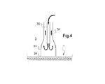
制御された冷却チャンバーは、全体的な制御された冷却を適用する。局所的な制御された冷却もそこで適用する場合には、このチャンバーは更に、この局所的な制御された冷却の適用に必要な手段を装備する。これらの手段は、例えば、重ねた板の面の一方へ局所的に吹付けるノズルでよい。それは、冷却すべき局所ゾーンとより速やかに接触する低温の金属の構成部品(例えば空気により内部から冷却される)でもよい。 A controlled cooling chamber applies global controlled cooling. If local controlled cooling is also applied there, the chamber is further equipped with the necessary means for the application of this local controlled cooling. These means may be, for example, nozzles that spray locally on one of the surfaces of the stacked plates. It may be a cold metal component (eg, cooled from the inside by air) that comes in quicker contact with the local zone to be cooled.
曲げ加工と冷却は両方とも、隣り合って配置した2つのガラス基材(すなわちそれらは、基材間にいかなる接着の手段もなしに、隣接し、特に重ね合わされている)に対して行うのが有利である。特に、2つの隣り合った基材を少なくとも1つの曲げ加工チャンバーへ移動させ、次いで少なくとも1つの制御された冷却チャンバーへ移動させることができ、局所的な制御された冷却は場合により最後の曲げ加工チャンバーで又は制御された冷却チャンバーで開始する。 Both bending and cooling should be performed on two glass substrates placed next to each other (ie they are adjacent, especially superposed, without any means of adhesion between the substrates). It is advantageous. In particular, two adjacent substrates can be moved to at least one bending chamber and then to at least one controlled cooling chamber, where local controlled cooling is optionally the last bending Start with a chamber or a controlled cooling chamber.
隣り合ったガラス基材の曲げ加工は、熱による曲げ加工に必要な温度を考慮して、それらの間に有機材料を置かずに行われる。熱による曲げ加工は、ポリマー材料の中間層が気泡の形成で160℃から劣化し始めるので、それを用いて集成する前に行われる。更に、そのような低温から冷却すると、ガラスに恒久的な端部圧縮応力を生じさせることは不可能である。 The bending process of adjacent glass substrates is performed without placing an organic material between them in consideration of the temperature required for the bending process by heat. The bending process with heat is performed before assembling with an intermediate layer of polymer material which begins to deteriorate from 160 ° C. due to the formation of bubbles. Furthermore, when cooled from such low temperatures, it is impossible to cause permanent edge compression stress in the glass.
ガラス基材の曲げ加工は、特に、国際公開第02/064519号パンフレット、国際公開第2006/072721号パンフレット、及び国際公開第2004/087590号パンフレットにより教示されるように、曲げ加工温度でのプレス及び/又は吸引によって行うことができる。この曲げ加工は、その後集成すべきガラス基材に対して、隣り合わせたやり方でもって行われる。特に、隣り合わせた2つのガラス基材は重力による事前の曲げ加工のためのチャンバーへ移動し、その後プレス及び/又は吸引チャンバーへ移動して、最終的に制御された冷却チャンバーへ移動することができ、局所的な制御された冷却は所望によりプレスの終わりで、又は冷却チャンバーで開始する。580℃より高い(一般には650℃と580℃の間の)温度で始まり、所望により最初に最後の曲げ加工チャンバーで始まる、制御された冷却の全体を冷却チャンバーで、少なくとも温度が520℃まで、あるいは更にこの温度未満に下がるまで、行う。 The bending of glass substrates is particularly performed by pressing at bending temperatures as taught by WO 02/064519, WO 2006/072721, and WO 2004/087590. And / or by aspiration. This bending is then performed in a side-by-side manner on the glass substrate to be assembled afterwards. In particular, two adjacent glass substrates can be moved to a chamber for pre-bending by gravity, then moved to a press and / or suction chamber and finally moved to a controlled cooling chamber. Locally controlled cooling is initiated at the end of the press or in the cooling chamber as desired. Start with a temperature higher than 580 ° C. (generally between 650 ° C. and 580 ° C.) and optionally start with the last bending chamber, the entire controlled cooling in the cooling chamber, at least to a temperature of 520 ° C., Alternatively, continue until the temperature drops below this temperature.
重ね合わせたガラス板がそれらの曲げ加工温度でまさに曲げられたところで、(全体的及び局所的な)制御された冷却を適用する。冷却工程の全体は一般に、曲げ加工温度から直ちに開始して行われる。局所的な制御された冷却を受けるゾーンの外側では、ガラスの温度は一般に、曲げ加工温度から周囲温度まで、戻ることなく低下する(単調な温度低下)。 Where the laminated glass plates are just bent at their bending temperature, controlled cooling (global and local) is applied. The entire cooling process is generally performed immediately starting from the bending temperature. Outside the zone subjected to local controlled cooling, the glass temperature generally decreases without returning from the bending temperature to the ambient temperature (monotonic temperature decrease).
集成しようとする2枚の板を隣り合った状態で同時に曲げることには、様々なガラス基材が任意選択的に異なる厚さと色のものでよいという利点がある。実際に、2つの基材は、それらの違いにもかかわらず、同じ曲率を確実に獲得する。 Bending the two plates to be assembled together side by side has the advantage that the various glass substrates can optionally be of different thicknesses and colors. In fact, the two substrates reliably acquire the same curvature despite their differences.
ガラス基材の曲げ加工は、ガラス基材に個別に(「シートごとに」)適用するプレス及び/又は吸引により行ってもよい。 The bending of the glass substrate may be performed by pressing and / or suction applied individually (“each sheet”) to the glass substrate.
曲げ加工は必ずしもチャンバー内で適用されるのでなく、曲げ加工用のツールは外気中にあることが可能である。 The bending process is not necessarily applied in the chamber, and the bending tool can be in the open air.
同様に、全体的及び局所的な制御された冷却は、必ずしもチャンバー内で適用されるとは限らない。 Similarly, global and local controlled cooling is not necessarily applied within the chamber.
好ましくは、全体的な制御された冷却の始まりは、ガラスの温度(曲げ加工作業を離れるときに650℃と580℃の間にある))が少なくとも520℃に達するまで、0.3℃/秒と8℃/秒の間で制御され、より好ましくは0.3℃/秒と2℃/秒の間で制御される。 Preferably, the onset of overall controlled cooling is 0.3 ° C./second until the glass temperature (which is between 650 ° C. and 580 ° C. when leaving the bending operation) reaches at least 520 ° C. And 8 ° C./second, and more preferably between 0.3 ° C./second and 2 ° C./second.
ガラス基材が局所的冷却以前に隣り合っている場合には、局所的な制御された冷却は2つの隣り合ったガラス基材の面の1つに向き合った1つの側から適用され、あるいは互いに向き合う2つの隣り合ったガラス基材に向き合った2つの側から適用される。局所的な制御された冷却を単一のガラス基材に対して適用する場合、隣り合った2つのガラス基材の厚みが大き過ぎず、そして局所的冷却の期間と強さが十分である限り、当然ながら、隣り合った2つのガラス基材の厚みの全体にわたりその効果が現れる。局所的な制御された冷却は、基材の積重体の単一の側から、厚さの全体にわたって適用して、全体的な制御された冷却よりも速い局所的な制御された冷却を保証することができる。それはまた、両側から適用してもよく、そしてこの場合おのおのの側に適用される冷却は互いに向き合わなくてはならない。 If the glass substrates are adjacent before local cooling, the local controlled cooling is applied from one side facing one of the faces of two adjacent glass substrates or each other. Applied from two sides facing two adjacent glass substrates facing each other. When local controlled cooling is applied to a single glass substrate, as long as the two adjacent glass substrates are not too thick and the period and strength of local cooling are sufficient Of course, the effect appears over the entire thickness of two adjacent glass substrates. Local controlled cooling can be applied across the thickness from a single side of the substrate stack to ensure faster local controlled cooling than global controlled cooling. be able to. It may also be applied from both sides, and in this case the cooling applied to each side must face each other.
局所的な制御された冷却の期間と強さは、積層集成体の切断後の端部応力が4MPaより大きく、好ましくは8MPaより大きくなるように、十分なものである。この調整は日常的な試験により容易に行うことができる。 The period and intensity of local controlled cooling is sufficient so that the edge stress after cutting the laminated assembly is greater than 4 MPa, preferably greater than 8 MPa. This adjustment can be easily performed by routine tests.
グレージングの全体的な制御された冷却は、周知のように、例えば対流、輻射、伝導、又はこれら3つの伝熱方法の組み合わせなどの、伝熱を利用することができる。 The overall controlled cooling of the glazing can utilize heat transfer, such as convection, radiation, conduction, or a combination of these three heat transfer methods, as is well known.
ここでは、局所的な制御された冷却を受けたゾーンを「圧縮ゾーン」と呼ぶことがある。 Here, a zone that has undergone local controlled cooling may be referred to as a “compression zone”.
圧縮ゾーンを得るためのガラス基材の差別化された局所的冷却は、任意の手段によって、例えば対流、又は輻射、又は伝導によって、あるいはこれらの手段の組み合わせによって、行うことができる。この局所的な差別化された冷却は、ガラス基材の集成後に切断しようとする線の全体を、グレージングの残りの部分よりも速く冷却するものである。 Differentiated local cooling of the glass substrate to obtain the compression zone can be effected by any means, for example by convection, or radiation, or conduction, or by a combination of these means. This local differentiated cooling is such that the entire line to be cut after assembly of the glass substrate cools faster than the rest of the glazing.
対流は、圧縮下に置くことが求められるゾーンに向けて低温の空気(周囲温度の空気)を吹付けるものである。グレージングの平均の冷却速度に応じて、吹付ける空気の温度及び/又は吹付けの強さが調整される。 Convection blows cold air (air at ambient temperature) toward a zone that is required to be placed under compression. Depending on the average cooling rate of the glazing, the temperature of the blowing air and / or the strength of the blowing is adjusted.
伝導は、冷却を求められるガラスの部分をガラス表面よりも冷たい材料とより速やかに接触させようとするものである。 Conduction seeks to bring the portion of the glass that is required to cool more quickly with a material that is cooler than the glass surface.
輻射に関しては、ガラスに対向して配置したより低温の材料を利用することが可能である。輻射による熱交換は、当該材料に面するゾーンの局所的冷却をより多くするのを可能にする。 With regard to radiation, it is possible to use lower temperature materials placed opposite the glass. Heat exchange by radiation allows more local cooling of the zone facing the material.
別の例によれば、圧縮応力を生じさせることが求められるゾーンの外側の冷却速度を制限するマスクが利用される。こうしてマスクの外側に、圧縮ゾーンに相当するゾーンが作り出され、そのためガラスの冷却がより増大する。 According to another example, a mask is utilized that limits the cooling rate outside the zone that is required to produce compressive stress. In this way, a zone corresponding to the compression zone is created outside the mask, thus increasing the cooling of the glass.
マスクの一例は、グレージングの表面積と同等の表面積を有し開口部が作られている断熱材料、特に繊維質材料である。この材料は、ガラスの冷却工程の間、高温のガラスの近くに配置される。低温雰囲気に置かれると、グレージングの開口部に向き合う部分はマスクされている部分よりも素早く冷却される。 An example of a mask is an insulating material, in particular a fibrous material, having a surface area equivalent to that of glazing and having openings. This material is placed close to the hot glass during the glass cooling process. When placed in a low temperature atmosphere, the portion facing the glazing opening cools faster than the masked portion.
このため、ガラスの放射率を増大させ又は低下させる被覆用材料を表面で使用することが可能である。 For this reason, it is possible to use a coating material on the surface that increases or decreases the emissivity of the glass.
ガラスの表面よりも放射率が大きい被覆物を用い、それを所望の圧縮ゾーンに向けて配置することが可能であり、この場合これらのゾーンはより素早く冷却される。 It is possible to use a coating with a higher emissivity than the surface of the glass and place it towards the desired compression zone, in which case these zones are cooled more quickly.
上の例とは逆に、ガラスの表面よりも放射率が小さい被覆物を用い、それを所望の圧縮ゾーンの外側のガラス表面に向けて配置することが可能であり、この場合これらのゾーンは圧縮下に置くべきゾーンよりゆっくりと冷却される。 Contrary to the above example, it is possible to use a coating with a lower emissivity than the surface of the glass and place it towards the glass surface outside the desired compression zone, where these zones are Cools more slowly than the zone to be placed under compression.
表面でガラスの放射率を増大させ又は低下させる材料としては、ガラスの表面をより容易に被覆するのを可能にする材料を用いることが可能である。この場合、それらは毒性がなく、耐熱性で、且つ水に容易に分散又は溶解することが好ましい。 As the material that increases or decreases the emissivity of the glass at the surface, it is possible to use a material that makes it possible to coat the surface of the glass more easily. In this case, it is preferred that they are non-toxic, heat resistant and easily dispersed or dissolved in water.
全体的な冷却の開始は、曲げ加工操作を離れるときの曲げ加工温度の580℃と650℃の間の終点から、ガラスの温度が520℃、あるいは更に低い温度に達するまでは、0.3℃/秒と2℃/秒の間で制御されるのが好ましい。 The start of the overall cooling is 0.3 ° C. from the end of the bending temperature between 580 ° C. and 650 ° C. when leaving the bending operation until the glass temperature reaches 520 ° C. or even lower. It is preferably controlled between 1 / second and 2 ° C./second.
520℃未満では、処理を加速するため、グレージング全体の対流による冷却を適用することが可能である。この時にはグレージングの全体が同じ全体的冷却を受けることができるので、局所的な制御された冷却を適用し続けることは無意味である。ガラスは、一般に300℃未満で任意選択的な冷却チャンバーから出てゆく。 Below 520 ° C., convection cooling of the entire glazing can be applied to accelerate the process. At this time, it is pointless to continue to apply local controlled cooling because the entire glazing can receive the same overall cooling. The glass exits the optional cooling chamber, generally below 300 ° C.
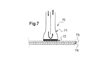
一例として、局所的な制御された冷却は、一端が切断しようとする線に吹付けるために好適な形状の断面を有し、切断しようとする線のところでガラス基材のうちの少なくとも一方に対向して取り付けられる、空気を吹付けるノズルを用いて適用される。例えば、切り取ろうとする線が円形である場合、ノズルの開口部は円板又はリングの形状を持つことができる。円板の場合は、円板の直径は切り取ろうとする円のそれよりわずかに大きく、そして局所的な制御された冷却を受けるのはその円内の全表面積である。リング形状のノズルの場合は、ノズルは円のリング状のゾーンに吹付け、このリングの内側には吹付けない。 As an example, the local controlled cooling has a cross-section suitable for blowing at one end to the line to be cut and faces at least one of the glass substrates at the line to be cut. Applied with an air blowing nozzle. For example, if the line to be cut is circular, the nozzle opening may have a disk or ring shape. In the case of a disc, the diameter of the disc is slightly larger than that of the circle to be cut, and it is the total surface area within that circle that receives local controlled cooling. In the case of a ring-shaped nozzle, the nozzle sprays into a circular ring-shaped zone and does not spray inside the ring.
別の実施形態として、あるいは組み合わせでもって、局所的な制御された冷却は、ガラスに向かうか又はそれによって放出される熱放射を増大又は減少させ、そして材料の種類に応じてグレージングの切断用の線を含むゾーンあるいは残りの部分(切断用の線を含まないゾーン)に対応する開口部を少なくとも1つ備えた、特に布帛タイプの、一時的な被覆材料を、ガラスの表面に対しまたはその近くに適用することによりなされる。この場合には、一時的被覆材料の適用の結果としてのガラスにより放出される熱放射の差に従って、差別化された冷却(切断しようとする線の隣の全体的な冷却よりも強力な、切断しようとする線の全体に及ぶ局所的冷却)が得られる。 As another embodiment or in combination, local controlled cooling increases or decreases the heat radiation directed to or emitted by the glass, and for glazing cutting depending on the type of material. Temporary coating material, particularly of the fabric type, with at least one opening corresponding to the zone containing the line or the rest (zone not containing the cutting line), at or near the glass surface It is made by applying to. In this case, according to the difference in the thermal radiation emitted by the glass as a result of the application of the temporary coating material, the differentiated cooling (cutting stronger than the overall cooling next to the line to be cut) Local cooling over the entire line to be obtained).
別の実施形態として、あるいは組み合わせでもって、局所的な制御された冷却は、ガラスの温度よりも低い温度の接触材料をガラスの表面に対し適用することによってなされ、接触するゾーンが切断しようとする線を含む。それは、熱衝撃を防ぐために金属製布帛で被覆された鋼などの低温の金属で製作された構成部品でよい。この低温の金属構成部品を低温に保つために、この構成部品を通して冷却剤(空気又は水)を流すことができる。ここでは、接触材料の適用の結果としてのガラスからの伝導による熱移動の差に従って、差別化された冷却(切断しようとするゾーンの隣での全体的冷却よりも速い局所的冷却)が得られる。 In another embodiment, or in combination, local controlled cooling is achieved by applying a contact material at a temperature below the glass to the surface of the glass so that the contacting zone attempts to cut. Includes lines. It may be a component made of a low temperature metal such as steel coated with a metal fabric to prevent thermal shock. In order to keep the cold metal component cool, coolant (air or water) can be flowed through the component. Here, differentiated cooling (local cooling faster than global cooling next to the zone to be cut) is obtained according to the difference in heat transfer due to conduction from the glass as a result of the application of the contact material. .
本発明の方法は、特に、切断の寸法がグレージングの特定の用途に適合させられる積層グレージングを提供する。 The method of the present invention provides, inter alia, laminated glazing where the dimensions of the cut are adapted to the particular application of the glazing.
本発明によると、切断された端部は、集成された2つのガラス基材に固定される機能部品(例えばアンテナ、ブレーキライト、カメラなど)の受け入れ用でよく、あるいは軸やケーブルの単純な通路として働き、及び/又は開放式サンルーフの開放部分を構成してもよい。 According to the present invention, the cut ends may be for receiving functional parts (eg antennas, brake lights, cameras, etc.) fixed to two assembled glass substrates, or simple passages for shafts and cables. And / or may constitute the open part of an open sunroof.
本発明はまた、少なくとも2つのガラス基材と、当該基材間に配置されたポリマー材料製の少なくとも1つの中間層とを含む積層グレージングであり、その厚みに少なくとも1つの切り取られた部分(孔又はノッチ)を含む積層グレージングであって、切り取られた部分における2つの基材の切断された輪郭が完全に重なっていること、そしてこれらの輪郭の端部の圧縮応力が4MPaより大きく、好ましくは8MPaより大きいことを特徴とする積層グレージングにも関する。端部の圧縮応力は、一般には20MPaより小さい。 The present invention is also a laminated glazing comprising at least two glass substrates and at least one intermediate layer made of a polymer material arranged between the substrates, the thickness of which is at least one cut-out part (hole Or a notch), wherein the cut contours of the two substrates in the cut-out portion are completely overlapping, and the compressive stress at the ends of these contours is greater than 4 MPa, preferably It also relates to a laminated glazing characterized by being greater than 8 MPa. The compressive stress at the end is generally less than 20 MPa.
積層グレージングは、切断部の端部が付形されていてもよく、例えば基材の少なくとも一方で、あるいは両方の基材で、面取りされていてもよい。 In the laminated glazing, the end of the cut portion may be shaped, and for example, it may be chamfered on at least one of the substrates or both substrates.
適用例として、積層グレージングは自動車の後部窓ガラスでよく、切断した材料はワイパー軸などの装備部品が通過するための孔(切り取られた部分)を構成することが可能である。孔の輪郭は、本発明による端部圧縮応力を有する。 As an example of application, the laminated glazing may be a rear window glass of an automobile, and the cut material can constitute a hole (a cut-out portion) through which equipment parts such as a wiper shaft pass. The contour of the hole has an end compressive stress according to the invention.
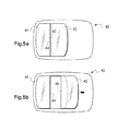
もう1つの適用例として、積層グレージングは開放式サンルーフを構成し、切断した材料は屋根の開口部を形成する切り取られた部分を構成することが可能である。この実施形態によると、切断部は全体が積層グレージングの主面内にある開口部を構成する。別の例によれば、本発明は車両の屋根の製造を可能にし、積層グレージングは、積層体として集成後に少なくとも2つの部分に切り分けられる開放式のサンルーフを構成し、それらの部分は本発明により切断が行われた箇所において完全に一致する。従って、このようなタイプの屋根は、屋根部分のうちの1つを移動させることにより、あるいは複数の屋根部分を移動させることによって、開放することができる。この種の応用に適した本発明による切断のタイプを、図3fに示す。このように、本発明はまた、本発明により積層され切断されたグレージングを作製する方法を含む、車両の開放式サンルーフを製造するための方法にも関し、その切断で、おのおのの部分が端部を含む2つの部分を製造し、その輪郭は他方の部分の端部と一致し、これら2つの端部は切断により作られていて、上記2つの部分は固定及び案内手段を用いて車両の開放式サンルーフとして搭載され、これら2つの部分は、2つの端部を並列することによって当該ルーフを閉じるために、あるいは2つの端部を切り離すことによって当該ルーフを開放するために、上記案内手段によりともに接近するよう移動させ、又は離隔するよう移動させることが可能である。これらの積層グレージング部分のうちの一方を移動できるよう車両に搭載してもよく、あるいは2つの部分を移動できるよう車両に取り付けてもよい。固定手段は、グレージングを2つの部分でもって車両に結合するものである。案内手段は、開放式サンルーフを開放し又は閉じる際に一方又は両方の部分を移動させるものである。この移動は、積層グレージングの一方又は両方の部分を移動させることによるルーフの開放と再閉鎖を可能にする、上昇とそれに続く平行移動又は回転、あるいはその他の任意の動作でよい。ルーフの開閉の際に離隔し又は近づくよう移動する部分の端部は、切断の際に作り出されるものであり、これがそれらが完全に一致する理由である。当然の結果として、ルーフを閉じると、これらの端部は切断の際に作られたのと同じ方位で接合する。 As another application, the laminated glazing can constitute an open sunroof and the cut material can constitute the cut-out part forming the roof opening. According to this embodiment, the cut portion constitutes an opening that is entirely within the main surface of the laminated glazing. According to another example, the present invention enables the manufacture of a vehicle roof, and the laminated glazing constitutes an open sunroof which is cut into at least two parts after assembly as a laminate, which parts are according to the invention. Matches exactly where the cut was made. Thus, this type of roof can be opened by moving one of the roof parts or by moving a plurality of roof parts. A type of cutting according to the invention suitable for this kind of application is shown in FIG. Thus, the present invention also relates to a method for manufacturing an open sunroof for a vehicle, including a method of making a laminated and cut glazing according to the present invention, wherein each part is an end portion. The two parts are made by cutting, and the two parts are opened using a fixing and guiding means to open the vehicle These two parts are mounted together by the guiding means to close the roof by juxtaposing the two ends, or to open the roof by separating the two ends. It can be moved closer or separated. One of these laminated glazing parts may be mounted on the vehicle so that it can be moved, or it may be attached to the vehicle so that two parts can be moved. The fixing means couples the glazing to the vehicle in two parts. The guide means moves one or both parts when opening or closing the open sunroof. This movement may be a lift and subsequent translation or rotation, or any other action that allows the roof to be opened and reclosed by moving one or both portions of the laminated glazing. The ends of the parts that move away or approach when the roof is opened and closed are created during cutting, which is why they are perfectly matched. Naturally, when the roof is closed, these ends join in the same orientation that was created during the cut.
切断工程は、ダイヤモンド孔鋸、ダイヤモンドルーター、又は水ジェットなどの周知の切断手段によって行われる。 The cutting process is performed by a known cutting means such as a diamond hole saw, a diamond router, or a water jet.
選択した切断手段に応じて、次の手段、すなわち、
・孔鋸またはルーター:好ましくは2つの主面を同時に切断する、
・水ジェット:片面で十分、
の1つにより積層集成体をその主面の一方から又は両面から一挙に切断することが可能である。
Depending on the cutting means selected, the following means:
-Hole saw or router: preferably cut two main faces simultaneously,
・ Water jet: one side is enough,
It is possible to cut the laminated assembly from one of its main surfaces or from both surfaces at once.
本発明による積層グレージング製造方法における工程数は、曲げ加工前に切断するための既知の方法に比べて少ない。更に、2つのガラス基材に沿って、且つ集成したグレージングの厚みにおいて、切断端部の完全な連続性を得ることが保証される。 The number of steps in the method for producing a laminated glazing according to the present invention is small compared to known methods for cutting before bending. In addition, it is ensured that complete continuity of the cut edge is obtained along the two glass substrates and in the thickness of the assembled glazing.
最後に、この製造方法は、積層グレージングが開放式サンルーフを構成する特定の用途において、その最大の利点が見いだされる。実際に、屋根の開口部を作るためにグレージングのくり抜き部の材料に相当する切断部分を回収することができるので、材料の節約になる。更に、2つのグレージング(一方は車両に固定される開口部を含むルーフ、他方はこの開口部を隠蔽する移動する部分)を2つの別々の製造方法で作製する場合に標準的な方法では現在得ることが困難である、開口部と開口部の周囲のルーフとの完全な幾何学的連続性が確保される。 Finally, this manufacturing method finds its greatest advantage in specific applications where laminated glazing constitutes an open sunroof. In fact, cuts corresponding to the material of the glazing cutout can be recovered to make the roof opening, thus saving material. In addition, the standard method currently obtains two glazings (one with a roof containing an opening fixed to the vehicle and the other with a moving part concealing the opening) by two separate manufacturing methods. Complete geometric continuity between the opening and the roof around the opening, which is difficult to do, is ensured.
本発明はまた、切断を可能にする少なくとも1つの局所的圧縮ゾーンを含む積層グレージングの製造を可能にする。このように、切断されていないが切断を可能にし、それを行うかどうかは取引先しだいである、圧縮ゾーンを含むこの種の積層グレージングを市場に出すことが可能である。従って、例えば、そのような切断されていないが切断可能であるグレージングを自動車ルーフとして搭載することが可能である。自動車の持ち主は、その自動車に開放式サンルーフを形成するため切断を行うか行わないかをその後決めることができる。言うまでもなく、圧縮ゾーンの箇所は、切断の箇所をはっきりと指定するよう製造業者によって正規に特定される。主面内に圧縮応力の局所的ゾーンを少なくとも1つ含む積層グレージングは、中間製品として、やはり本発明の対象である。圧縮応力のこの局所的なゾーンは、圧縮応力の周縁部を形成するグレージングの外側端部の圧縮応力とは異なる。圧縮応力の局所的ゾーンは、端部圧縮応力のこの縁部内にある。しかし、局所的ゾーンは、端部圧縮応力の縁部とつながってもよい。よって、本発明はまた、少なくとも2つのガラス基材を含むとともに、ガラス基材のおのおのにおいて且つ全てのガラス基材において互いに向き合って(圧縮ゾーンは同じ箇所に配置され、すなわち積層グレージングにおいて1つのガラス基材から次のものへ重ね合わされる)、4MPaより大きく、好ましくは8MPaより大きい圧縮端部応力を有する端部を切断後に形成するため、当該ゾーンに含まれる線に沿って当該グレージングを切断するのを可能にする圧縮応力を含むゾーンを局所的に含む、積層グレージングにも関する。一般に、切断後の圧縮端部応力は20MPa未満である。従って、グレージングは、圧縮応力の局所的ゾーンに開口部を含まずに製造することができる。このゾーンでの切断は、自動車の持ち主の指示を受けてから行われ、そして例えば、開放式サンルーフを作るため、あるいはルーフバーの固定用の孔を開けるために、利用することができる。よって、本発明はまた、車両への搭載後に積層グレージングに孔を開けるのを可能にする圧縮応力を含む積層グレージングを含む車両屋根(一般に自動車ルーフ)にも関する。 The present invention also allows the production of laminated glazing comprising at least one local compression zone that allows cutting. In this way, it is possible to market this type of laminated glazing, including a compression zone, which is not cut but allows cutting and it is up to the customer to do so. Therefore, for example, it is possible to mount such a glazing that is not cut but can be cut as an automobile roof. The car owner can then decide whether or not to cut to form an open sunroof in the car. Needless to say, the location of the compression zone is formally specified by the manufacturer to clearly specify the location of the cut. Laminated glazing comprising at least one local zone of compressive stress in the main surface is also an object of the present invention as an intermediate product. This local zone of compressive stress is different from the compressive stress at the outer edge of the glazing that forms the periphery of the compressive stress. The local zone of compressive stress is within this edge of end compressive stress. However, the local zone may be connected to the edge of the end compressive stress. Thus, the present invention also includes at least two glass substrates and faces each other in each glass substrate and in all glass substrates (the compression zones are located at the same location, ie one glass in laminated glazing). The glazing is cut along the line included in the zone to form after cutting an end having a compressed end stress greater than 4 MPa, preferably greater than 8 MPa. It also relates to laminated glazing, locally including zones containing compressive stresses that enable Generally, the compression end stress after cutting is less than 20 MPa. Thus, glazing can be produced without including openings in the local zone of compressive stress. Cutting in this zone takes place upon the direction of the vehicle owner and can be used, for example, to make an open sunroof or to drill holes for fixing roof bars. Thus, the present invention also relates to a vehicle roof (generally an automobile roof) that includes laminated glazing that includes compressive stresses that allow the laminated glazing to be perforated after installation in a vehicle.
周縁部の圧縮端部応力は、一般に4MPaと20MPaの間である。圧縮端部応力の縁部は一般に、グレージングのおのおのの主面に、外側端部から続く0.1〜3cmの幅を有する。 The compressive edge stress at the periphery is generally between 4 MPa and 20 MPa. The edge of the compressive end stress generally has a width of 0.1 to 3 cm following each major surface of the glazing from the outer end.
本発明により「切断しようとする」積層グレージングは、一般に、その前方横方向の帯状部分の中央と後方横方向の帯状部分の中央とを通過する長手方向の正中面に関して対称である(「長手」方向とは車両の移動の方向に相当し、「横」方向はそれに垂直である)。この正中面はその重心も通過する。本発明による積層グレージングは、圧縮応力の局所的ゾーンを少なくとも2つ含むことができ、これらのゾーンは、当該ゾーン内に孔を開けた後に、ルーフバーを取り付け、その孔を通り抜ける当該バーの構成部品を固定することを可能にする。これらの圧縮応力のゾーンは、グレージングの前方横方向の帯状部分の中央と後方横方向の帯状部分の中央とを通過するグレージングの対称面に関して、一般に対称的に配置される。ルーフバーの固定を可能にする車両屋根としての用途向けの本発明による積層グレージングは、2つ、4つ又は6つの局所的な圧縮応力のゾーンを含み、これらのゾーンが、当該ゾーンに開口部を開けた後に、2つのルーフバーの固定用部品の通過を可能にする。この用途のためには、圧縮応力の各ゾーンは一般に0.5cm2と70cm2の間の面積を有する。圧縮応力の各ゾーンは、屋根として働く積層グレージングの長手方向の端部から一般に30cm未満であり、より一般的には20cm未満である。 Laminated glazing “sought to cut” according to the present invention is generally symmetric with respect to a longitudinal median plane passing through the center of its front lateral strip and the center of its rear lateral strip (“long”). The direction corresponds to the direction of movement of the vehicle and the “lateral” direction is perpendicular to it). This median plane also passes through its center of gravity. The laminated glazing according to the present invention can comprise at least two local zones of compressive stress, which are the components of the bar that pass through the holes after the holes are drilled in the zones. Makes it possible to fix. These zones of compressive stress are generally arranged symmetrically with respect to the plane of symmetry of the glazing passing through the center of the front lateral strip and the center of the rear lateral strip of the glazing. Laminated glazings according to the invention for applications as vehicle roofs that allow the fixing of roof bars include two, four or six zones of local compressive stress, which zones have openings in the zones. After opening, it allows passage of the fixing parts of the two roof bars. For this application, each zone of compressive stress generally has an area between 0.5 cm 2 and 70 cm 2 . Each zone of compressive stress is typically less than 30 cm and more typically less than 20 cm from the longitudinal edge of the laminated glazing that serves as the roof.
次に、本発明の範囲を少しも限定しない全くの説明用の例を活用し、そして添付の図面を利用して、本発明を説明する。 The present invention will now be described with the aid of a fully illustrative example, which does not limit the scope of the invention in any way, and with reference to the accompanying drawings.
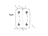
図1は、厚みに応じて、少なくとも1つの切り取られた部分2を含む積層グレージング1の部分断面図を示している。このグレージングは、少なくとも2つのガラス板又は基材10及び12と、これらのガラス基材の間に配置されたポリマー材料製の中間層又は中間シート11を含む。製造後に、グレージングは、2つのガラス基材と中間層とにそれらの集成後に孔を開けて得られた切り取られた部分2を有する。第1の基材に得られ孔は輪郭20を有する一方、第2の基材における他方の孔は輪郭21を有する。本発明の製造方法によれば、
・2つの輪郭20と21は完全に重なり合い、断面図によれば、これらの輪郭の全周に及ぶ基材の端部は完全に整合していて、当然ながら、孔開けをグレージングの2つの主面から同時に行う場合には、グレージングのそれぞれの側の孔開け工具を確実に整合させることが望ましい。特に、水ジェットでの切断を積層グレージングの単一の側から行うことができる。
・輪郭20と21は両方とも、4MPaより大きい、好ましくは8MPaより大きい、圧縮端部応力を有する。
FIG. 1 shows a partial cross-sectional view of a
The two
Both
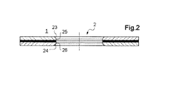
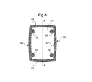
基材の孔は、用途に応じて形作られる。例えば、図2は、2つの輪郭25及び26の外側端部のおのおのに面取り部23及び24を有するくり抜き部分2を示している。このくり抜き部分は、例えば、アンテナ、ファン、化粧縁などの機能性もしくは装飾性部品を取り付けるのに用いられ、あるいはケーブルなどの通り道として用いられる。寸法が大きい場合には、このくり抜き部分は、車両用の、特に自動車用の、開放式ガラスサンルーフの開口部を構成することができる。
The holes in the substrate are shaped according to the application. For example, FIG. 2 shows a
グレージングを製造するための方法は、次に説明する種々の工程を含む。まず、大まかな切断、付形のための切断、そのブレイクアウト及び任意選択的なその成形に応じて、所望の外周形状を有する基材を提供するため、ガラスを切断するための標準的な方法により、個々のガラス基材10及び12をそれらの外縁に沿って切断する。用途に応じて、1以上の任意選択的な追加のスクリーン印刷の工程を行ってもよい。製造ラインで、こうして多くの基材を連続運転により準備する。次に、基材を製造ラインで流して一組にする工程を行う。基材10と12を重ね合わせることで一緒にする。次いで、重ね合わせた基材を選定した曲げ加工の方法により一緒に曲げて所望の形状にする。この曲げ加工工程のためのガラス基材の重ね合わせは、完全に一致した全体的形状を有するガラスを得るのを可能にする。次に、本発明により、全体的及び局所的な制御された冷却の工程を行う。局所的冷却は、隣り合った基材の周辺面の、処理の最後に切断されるゾーンに少なくとも対応する少なくとも1つのゾーンで行う。局所的な制御された冷却の目的は、切断される端部でグレージングの厚さの圧縮ゾーンを得ることである。
The method for producing glazing includes various steps described below. First, a standard method for cutting glass to provide a substrate with a desired outer shape according to rough cutting, cutting for shaping, its breakout and optionally its shaping To cut the
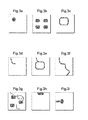
切断しようとするゾーンにおける冷却の局所化は、表面と輪郭の両方を対象とする。局所化した冷却は、特に、一方の端部から他方の端部へと、あるいは1つの端部から同じ端部へと、グレージングを横切る単一の線に沿って行うことができる。図3a〜3iは、いろいろな形状のゾーンに対する局所的な制御された冷却の限定しない典型的な実施形態を示している。 The localized cooling in the zone to be cut covers both the surface and the contour. Localized cooling can be performed along a single line across the glazing, particularly from one end to the other end, or from one end to the same end. 3a-3i show non-limiting exemplary embodiments of localized controlled cooling for various shaped zones.
図3aは、閉じた円形の輪郭の形をしており、この円により境界を画定された表面(斜線表示の表面)を有し、例えば図1のグレージングを得るのを可能にする、局所的圧縮ゾーンを提示している。 FIG. 3a is in the form of a closed circular contour, having a surface delimited by this circle (surface with diagonal lines), for example allowing a local glazing of FIG. 1 to be obtained. The compression zone is presented.
図3bは、互いに独立した複数の局所表面圧縮ゾーンを示している。 FIG. 3b shows multiple local surface compression zones that are independent of each other.
図3cは、単一の閉じた輪郭の形をしたゾーンであり、輪郭の内側が当該ゾーンの一部ではない、局所圧縮ゾーンを図示している。 FIG. 3c illustrates a zone with a single closed contour shape, where the inside of the contour is not part of that zone.
図3dは、グレージングの端部のうちの1つだけに達する曲線の形をした局所圧縮ゾーンを示している。 FIG. 3d shows a local compression zone in the form of a curve that reaches only one of the ends of the glazing.
図3eは、閉じたループの形を取るとともに、このループからグレージングの端部に至る曲線を有する局所圧縮ゾーンを示している。 FIG. 3e shows a local compression zone which takes the form of a closed loop and has a curve from this loop to the end of the glazing.
図3fは、グレージングの一方の端部から出発して向かい側の端部に達する曲線(この線は出発した端部に隣り合った端部へ戻ることもできる)の形をした局所圧縮ゾーンを示している。 FIG. 3f shows a local compression zone in the form of a curve starting from one end of the glazing and reaching the opposite end (this line can also return to the end adjacent to the starting end). ing.
図3gに例示したように、グレージングの端部に達してもよく達しなくてもよい1以上の線を使って、独立した局所圧縮ゾーンを接続することも可能である。 As illustrated in FIG. 3g, it is possible to connect independent local compression zones using one or more lines that may or may not reach the end of the glazing.
図3hと3iは、グレージングの1つの端部から始まって特定のノッチを形成し、グレージングの同じ端部に達する圧縮表面を示している。 Figures 3h and 3i show a compressed surface starting from one end of the glazing to form a particular notch and reaching the same end of the glazing.
図4は、隣り合った基材の片側へ吹付けるのに好適な装置3を模式的に示している。ここでは、図1及び2のくり抜き部分を後に作製することを目的に、図3aに示した円板状の領域に周囲温度の空気を吹付ける。吹付けの時間はおおよそ40秒と90秒の間である。吹付けの時間は、差別化したやり方で冷却しようとする表面積とは無関係であるが、その一方でガラスの厚みに依存する。40秒の局所冷却は、おのおのの厚さが2.1mmである基材について設定される。吹付けノズルは、得ようとする圧縮応力の局所ゾーンの幾何学形状に適合した形状を持つ末端部を有する。それは、特に、開放式サンルーフの用途を対象とするもののような比較的大きな寸法のくり抜き部分のための長方形の輪郭の形状を有することができる。図4において、ノズル3は、中央の空気供給流路30と、この中央空気供給流路30の周囲の軸対称の流路31を含んでいる。流路31は、ノズルの末端としての、円筒状のベル33へ通じていて、その壁は金属繊維を基礎材料とする軟質のフェルトで構成されている。ベルのつながれていない端部34は、ガラスの表面に寄せて配置される。低温の空気を、冷却しようとするガラスの表面に向けて放出するため、供給流路30を通してベル34へ送り、その後流路31を介して排出する。冷却後、2つの基材10と12の組を解消(分離)する。次に、中間層12とともに集成する工程、集成体の脱気をする工程、そしてオートクレーブへ送る工程を、標準的なやり方でもって行う。この処理により、中間層のそれぞれの側で中間層とガラス基材とが結合される。最後に、所望の切り取られた1又は複数の部分を得るために、局所冷却を受けたゾーンでグレージングの切断を行う(ダイヤモンド孔鋸、ダイヤモンドルーター、水ジェットなどにより)。
FIG. 4 schematically shows a
図5は、開放式サンルーフとして機能する本発明による積層グレージングを含む自動車屋根40を例示しており、このグレージングは2つの部分41と40になっていて、グレージングの一方の部分41は車両に対して固定され、他方の部分42は可動である。図5aでは、屋根は閉じている。図5bでは、部分42のみが移動(矢印)して車両のルーフパネルの囲い込まれた本体に収まることで、屋根は開放している。本発明により、最初に、まだ切断されていない2つの部分41と42を初めから含む単一の積層グレージングを製造する。本発明により、グレージングを完全に横切る線(切断後に端部44と45を生じさせる線)でこのグレージングを切断する箇所に、圧縮応力の局所ゾーンを作り出す。この線のところで本発明による切断を行って、完全に独立しているが屋根を閉じたときに端部44と45とが完全に一致する部分41と42(図5a)が得られる。
FIG. 5 illustrates an
図6は、積層ガラスで製作したグレージング1を示している。斜線表示の4つの円板2が、孔、あるいは孔開けを可能にする圧縮応力の局所ゾーンを表している。これらの孔又は圧縮応力の局所ゾーンは、ここでは、グレージングの外側端部まで突き出す(ノッチの場合のように)ことなく、完全にグレージングの主面3の範囲内にある。これらの孔は、パネル1の前方帯状部分6の中央5と後方帯状部分8の中央7とを通過する対称平面4に関して対称的に配置される。
FIG. 6 shows a
図7は、隣り合わせた2つの基材73と74の積重体の主面を通して、伝導により局所ゾーンを冷却するのに好適な装置70を模式的に示している。下端を閉じた金属管71に、矢印で示したように低温の空気を流す。金属管とガラスとの接触は、熱衝撃による破損の危険を減らすため、耐熱性繊維で製作したフェルト72を用いることで和らげられる。この結果、フェルト72とガラスとが接触する箇所で圧縮応力の局所ゾーンが形成される。
FIG. 7 schematically shows a
図8は、主面81の1つに対して垂直に見た、積層グレージングを含む自動車屋根を示している。この積層グレージングは、横方向の2つの端部87及び88と、長手方向の2つの端部89及び90を含んでいる。それは、グレージングの周囲を完全にめぐる圧縮端部応力の縁部82を含んでいる。長手方向の正中面AA’(図に対して垂直)がグレージングの対称面であり、これは互いに相対する横方向の端部87と88に対して垂直である。圧縮端部応力の縁部の範囲内に、圧縮応力の4つの局所ゾーン83、84、85、86がある。ここでは、これらの局所ゾーンは縁部に交わっている。これらの圧縮ゾーンは斜線で表されているが、実際にはそれらは肉眼には見えない。局所ゾーン83と84は、対称平面AA’に関して互いに対称に配置されている。局所ゾーン85と86は、対称平面AA’に関して互いに対称に配置されている。これらの局所ゾーンは、ルーフバーの固定用部品が通り抜けるための孔を積層グレージングを貫通して開けるのを可能にする。2つのルーフバーを、1つは箇所83と85の間で、他方は箇所84と86の間で、対称面AA’に対して平行に、あるいは1つは箇所83と84の間で、他方は箇所85と86の間で、対称面AA’に対して垂直に、取り付けることができる。
本発明の態様としては、以下を挙げることができる:
《態様1》
少なくとも2つのガラス基材とこれらの基材間に配置されるポリマー材料製の少なくとも1つの中間層とを含む積層グレージングを製造するための方法であり、基材の曲げ加工、基材の制御された冷却、ガラス基材と中間層との集成を含む積層グレージングの製造方法であって、次の工程、すなわち、
・基材を曲げ加工する工程、
・基材の制御された冷却を行う工程、
・基材と中間層とを含む積層集成体を形成する工程、
・積層集成体をその主面のうちの1つにおける線に沿ってその厚み全体を通して切断する工程、
をこの順番に含み、上記の制御された冷却は、全体的な制御された冷却と、切断する上記の線を含むゾーンの局所的な制御された冷却とを含み、局所的な制御された冷却の方が全体的な制御された冷却よりも速いことを特徴とする、積層グレージングの製造方法。
《態様2》
局所的な制御された冷却を、対流、伝導、輻射、又はこれらの手段の組み合わせにより行うことを特徴とする、態様1記載の方法。
《態様3》
曲げ加工と全体的及び局所的冷却を隣り合わせて配置した2つのガラス基材に対して行うことを特徴とする、態様1又は2記載の方法。
《態様4》
局所的な制御された冷却を2つの隣り合わせたガラス基材の面の1つに向けて片側から適用することを特徴とする、態様1から3までのいずれか1つに記載の方法。
《態様5》
局所的な制御された冷却を互いに向き合う隣り合わせた2つのガラス基材の2つの相対する側から向かい合わせに適用することを特徴とする、態様1から3までのいずれか1つに記載の方法。
《態様6》
隣り合わせた2つの基材を少なくとも1つの曲げ加工チャンバーへ、そして少なくとも1つの冷却チャンバーへ移動させて、局所的な制御された冷却を曲げ加工チャンバーで又は冷却チャンバーで開始することを特徴とする、態様3記載の方法。
《態様7》
曲げ加工を580℃と650℃の間で行うこと、そして全体的冷却の開始を、少なくともガラスの温度が520℃に達するまで、0.3℃/秒と8℃/秒の間、好ましくは0.3℃/秒と2℃/秒の間で制御することを特徴とする、態様1から6までのいずれか1つに記載の方法。
《態様8》
局所的な制御された冷却を、一端が前記切断する線を含むゾーンに対応した形状の断面を有するノズルを用いて空気を吹付けることにより適用することを特徴とする、態様1から7までのいずれか1つに記載の方法。
《態様9》
局所的な制御された冷却を、前記切断する線を含むゾーンの形状に対応した形状を有し、ガラスの温度より低い温度を有する材料を用いて適用し、当該材料をガラス基材のうちの少なくとも一方と当該ゾーンで接触させることを特徴とする、態様1から7までのいずれか1つに記載の方法。
《態様10》
局所的な制御された冷却を、前記切断する線を含むゾーンの形状に対応した形状を有し、ガラスの温度より低い温度を有する材料を用いて適用し、当該材料をガラス基材のうちの少なくとも一方の当該ゾーンと、接触させずに向かい合わせることを特徴とする、態様1から7までのいずれか1つに記載の方法。
《態様11》
局所的な制御された冷却を、少なくとも1つの開口部を備えた、ガラスの放射率を上昇させるか又は減少させる一時的な被覆材料、特に布帛タイプの被覆材料を、ガラスの表面に向けて適用することにより行うことを特徴とする、態様1から10までのいずれか1つに記載の方法。
《態様12》
切断を孔鋸、ルーター又は水ジェットにより行うことを特徴とする、態様1から11までのいずれか1つに記載の方法。
《態様13》
切断で、積層グレージングの厚さ全体に及ぶ孔又はノッチを作製することを特徴とする、態様1から12までのいずれか1つに記載の方法。
《態様14》
局所的な制御された冷却が、積層集成体の切断後の端部応力が4MPaより大きく、好ましくは8MPaより大きくなるのに時間的及び強度的に十分であることを特徴とする、態様1〜13までのいずれか1つに記載の方法。
《態様15》
車両の開放式サンルーフを製造するための方法であって、態様1から14までの1つに記載の方法を含み、切断によりおのおのの部分が端部を含む2つの部分を製造し、その輪郭は他方の部分の端部と一致し、これら2つの端部は当該切断により作られていて、上記2つの部分は固定及び案内手段を用いて車両の開放式サンルーフとして搭載され、これら2つの部分は、2つの端部を並列することによって当該ルーフを閉じるために、あるいは2つの端部を切り離すことによって当該ルーフを開放するために、上記案内手段によりともに接近するよう移動させ、又は離隔するよう移動させることが可能である、車両の開放式サンルーフを製造するための方法。
《態様16》
態様1から14までのいずれか1つに記載したとおりにして得られた、厚み方向に切断した少なくとも1つの端部を含む積層グレージング。
《態様17》
少なくとも2つのガラス基材とこれらの基材間に配置されたポリマー材料製の少なくとも1つの中間層とを含むとともに、厚み方向に切断した少なくとも1つのノッチ又は開口部を含む積層グレージングであって、2つのガラス基材のノッチ又は開口部の切断された輪郭が完全に重なり合うこと、そしてこれらの輪郭の圧縮端部応力が4MPaより大きく、好ましくは8MPaより大きいことを特徴とする積層グレージング。
《態様18》
ガラス基材の少なくとも一方で、ノッチ又は開口部が面取りされているか又は成形されていることを特徴とする、態様17記載の積層グレージング。
《態様19》
曲げ加工されていることを特徴とする、態様17又は18記載の積層グレージング。
《態様20》
態様16から19までの1つに記載の積層グレージングを含み、厚み方向に切断された開口部を含む車両の開放式サンルーフであって、開口部を作るため切断された材料が当該サンルーフの開口部を構成していることを特徴とする車両の開放式サンルーフ。
《態様21》
接近して一緒になるよう移動することができ又は離隔するよう移動することができる少なくとも2つの部分を含む積層グレージングで製作され、これらの部分は接近して一緒になるよう移動させようとする部分の端部が完全に一致するとともに、グレージングの全ての曲率が一致している、車両の開放式サンルーフ。
《態様22》
態様16から19までの1つに記載の積層グレージングを含み、当該積層グレージングがワイパー軸などの装備部品を通すための開口部を含んでおり、当該開口部の輪郭が圧縮端部応力を有している、自動車の後部窓ガラス。
《態様23》
少なくとも2つのガラス基材を含む積層グレージングであって、圧縮端部応力の縁部を含むとともに、ガラス基材のおのおのに且つ重ね合わせた全てのガラス基材に、開口部がなく当該縁部とは異なる圧縮応力の局所ゾーンを局所的に含んでいて、切断後に圧縮端部応力が4MPaより大きい、好ましくは8MPaより大きい端部を形成するため、当該局所ゾーンの範囲内の線に沿って当該グレージングを切断できる積層グレージング。
《態様24》
態様23記載のグレージングを含む車両屋根。
FIG. 8 shows an automobile roof including laminated glazing, viewed perpendicular to one of the major surfaces 81. The laminated glazing includes two lateral ends 87 and 88 and two
Embodiments of the present invention can include the following:
<<
A method for producing a laminated glazing comprising at least two glass substrates and at least one intermediate layer made of a polymer material disposed between the substrates, the bending of the substrate, the controlled substrate And a method for producing a laminated glazing including assembly of a glass substrate and an intermediate layer, the following steps:
・ Bending process of base material,
A process for controlled cooling of the substrate,
A step of forming a laminated assembly including a base material and an intermediate layer,
Cutting the laminated assembly through its thickness along a line in one of its major faces;
In this order, the controlled cooling includes global controlled cooling and local controlled cooling of the zone containing the line to be cut, and is locally controlled cooling A process for producing laminated glazing, characterized in that is faster than the overall controlled cooling.
<<
A method according to
<<
3. A method according to
<< Aspect 4 >>
A method according to any one of
<< Aspect 5 >>
A method according to any one of
<< Aspect 6 >>
Moving two adjacent substrates to at least one bending chamber and then to at least one cooling chamber, and starting local controlled cooling in the bending chamber or in the cooling chamber, A method according to
<<
The bending is performed between 580 ° C. and 650 ° C., and the start of the overall cooling is between 0.3 ° C./sec and 8 ° C./sec, preferably 0 until at least the glass temperature reaches 520 ° C. A method according to any one of
<< Aspect 8 >>
<< Aspect 9 >>
Local controlled cooling is applied using a material having a shape corresponding to the shape of the zone containing the cutting line and having a temperature lower than that of the glass; A method according to any one of
<<
Local controlled cooling is applied using a material having a shape corresponding to the shape of the zone containing the cutting line and having a temperature lower than that of the glass; The method according to any one of
<<
Applying local controlled cooling to the surface of the glass with a temporary coating material, in particular a fabric-type coating material, which increases or decreases the emissivity of the glass with at least one opening The method according to any one of
<<
A method according to any one of
<< Aspect 13 >>
A method according to any one of
<< Aspect 14 >>
<< Aspect 15 >>
A method for manufacturing an open sunroof for a vehicle, comprising the method according to one of
<< Aspect 16 >>
Laminated glazing comprising at least one end cut in the thickness direction, obtained as described in any one of
<< Aspect 17 >>
A laminated glazing comprising at least two glass substrates and at least one intermediate layer made of a polymer material disposed between the substrates, and comprising at least one notch or opening cut in the thickness direction; Laminated glazing characterized in that the cut contours of the notches or openings of the two glass substrates completely overlap and that the compression end stress of these contours is greater than 4 MPa, preferably greater than 8 MPa.
<< Aspect 18 >>
Laminated glazing according to aspect 17, characterized in that at least one of the glass substrates has a notch or an opening chamfered or shaped.
<< Aspect 19 >>
The laminated glazing according to aspect 17 or 18, wherein the laminated glazing is bent.
<<
An open sunroof for a vehicle comprising laminated glazing according to one of aspects 16 to 19 and including an opening cut in the thickness direction, wherein the material cut to make the opening is the opening of the sunroof An open type sunroof for a vehicle characterized by comprising:
<<
Made of laminated glazing that includes at least two parts that can be moved closer together or can be moved apart, these parts being moved closer together The open sunroof of the vehicle, where the ends of the spheres are perfectly matched and all the glazing curvatures are matched.
<< Aspect 22 >>
A laminated glazing according to one of aspects 16 to 19, wherein the laminated glazing includes an opening for passing equipment parts such as a wiper shaft, and the contour of the opening has a compression end stress. The rear window glass of the car.
<<
Laminated glazing comprising at least two glass substrates, including edges of compression end stress, and each glass substrate and each of the laminated glass substrates without openings and said edges Includes locally local zones of different compressive stresses, and forms an end with a compressive end stress greater than 4 MPa, preferably greater than 8 MPa after cutting, so that along the line within the local zone Laminated glazing that can cut glazing.
<<
24. A vehicle roof including the glazing according to
図8は、主面81の1つに対して垂直に見た、積層グレージングを含む自動車屋根を示している。この積層グレージングは、横方向の2つの端部87及び88と、長手方向の2つの端部89及び90を含んでいる。それは、グレージングの周囲を完全にめぐる圧縮端部応力の縁部82を含んでいる。長手方向の正中面AA’(図に対して垂直)がグレージングの対称面であり、これは互いに相対する横方向の端部87と88に対して垂直である。圧縮端部応力の縁部の範囲内に、圧縮応力の4つの局所ゾーン83、84、85、86がある。ここでは、これらの局所ゾーンは縁部に交わっている。これらの圧縮ゾーンは斜線で表されているが、実際にはそれらは肉眼には見えない。局所ゾーン83と84は、対称平面AA’に関して互いに対称に配置されている。局所ゾーン85と86は、対称平面AA’に関して互いに対称に配置されている。これらの局所ゾーンは、ルーフバーの固定用部品が通り抜けるための孔を積層グレージングを貫通して開けるのを可能にする。2つのルーフバーを、1つは箇所83と85の間で、他方は箇所84と86の間で、対称面AA’に対して平行に、あるいは1つは箇所83と84の間で、他方は箇所85と86の間で、対称面AA’に対して垂直に、取り付けることができる。
本発明の態様としては、以下を挙げることができる:
《態様1》
少なくとも2つのガラス基材とこれらの基材間に配置されるポリマー材料製の少なくとも1つの中間層とを含む積層グレージングを製造するための方法であり、基材の曲げ加工、基材の制御された冷却、ガラス基材と中間層との集成を含む積層グレージングの製造方法であって、次の工程、すなわち、
・基材を曲げ加工する工程、
・基材の制御された冷却を行う工程、
・基材と中間層とを含む積層集成体を形成する工程、
・積層集成体をその主面のうちの1つにおける線に沿ってその厚み全体を通して切断する工程、
をこの順番に含み、上記の制御された冷却は、全体的な制御された冷却と、切断する上記の線を含むゾーンの局所的な制御された冷却とを含み、局所的な制御された冷却の方が全体的な制御された冷却よりも速いことを特徴とする、積層グレージングの製造方法。
《態様2》
局所的な制御された冷却を、対流、伝導、輻射、又はこれらの手段の組み合わせにより行うことを特徴とする、態様1記載の方法。
《態様3》
曲げ加工と全体的及び局所的冷却を隣り合わせて配置した2つのガラス基材に対して行うことを特徴とする、態様1又は2記載の方法。
《態様4》
局所的な制御された冷却を2つの隣り合わせたガラス基材の面の1つに向けて片側から適用することを特徴とする、態様1から3までのいずれか1つに記載の方法。
《態様5》
局所的な制御された冷却を互いに向き合う隣り合わせた2つのガラス基材の2つの相対する側から向かい合わせに適用することを特徴とする、態様1から3までのいずれか1つに記載の方法。
《態様6》
隣り合わせた2つの基材を少なくとも1つの曲げ加工チャンバーへ、そして少なくとも1つの冷却チャンバーへ移動させて、局所的な制御された冷却を曲げ加工チャンバーで又は冷却チャンバーで開始することを特徴とする、態様3記載の方法。
《態様7》
曲げ加工を580℃と650℃の間で行うこと、そして全体的冷却の開始を、少なくともガラスの温度が520℃に達するまで、0.3℃/秒と8℃/秒の間、好ましくは0.3℃/秒と2℃/秒の間で制御することを特徴とする、態様1から6までのいずれか1つに記載の方法。
《態様8》
局所的な制御された冷却を、一端が前記切断する線を含むゾーンに対応した形状の断面を有するノズルを用いて空気を吹付けることにより適用することを特徴とする、態様1から7までのいずれか1つに記載の方法。
《態様9》
局所的な制御された冷却を、前記切断する線を含むゾーンの形状に対応した形状を有し、ガラスの温度より低い温度を有する材料を用いて適用し、当該材料をガラス基材のうちの少なくとも一方と当該ゾーンで接触させることを特徴とする、態様1から7までのいずれか1つに記載の方法。
《態様10》
局所的な制御された冷却を、前記切断する線を含むゾーンの形状に対応した形状を有し、ガラスの温度より低い温度を有する材料を用いて適用し、当該材料をガラス基材のうちの少なくとも一方の当該ゾーンと、接触させずに向かい合わせることを特徴とする、態様1から7までのいずれか1つに記載の方法。
《態様11》
局所的な制御された冷却を、少なくとも1つの開口部を備えた、ガラスの放射率を上昇させるか又は減少させる一時的な被覆材料、特に布帛タイプの被覆材料を、ガラスの表面に向けて適用することにより行うことを特徴とする、態様1から10までのいずれか1つに記載の方法。
《態様12》
切断を孔鋸、ルーター又は水ジェットにより行うことを特徴とする、態様1から11までのいずれか1つに記載の方法。
《態様13》
切断で、積層グレージングの厚さ全体に及ぶ孔又はノッチを作製することを特徴とする、態様1から12までのいずれか1つに記載の方法。
《態様14》
局所的な制御された冷却が、積層集成体の切断後の端部応力が4MPaより大きく、好ましくは8MPaより大きくなるのに時間的及び強度的に十分であることを特徴とする、態様1〜13までのいずれか1つに記載の方法。
《態様15》
車両の開放式サンルーフを製造するための方法であって、態様1から14までの1つに記載の方法を含み、切断によりおのおのの部分が端部を含む2つの部分を製造し、その輪郭は他方の部分の端部と一致し、これら2つの端部は当該切断により作られていて、上記2つの部分は固定及び案内手段を用いて車両の開放式サンルーフとして搭載され、これら2つの部分は、2つの端部を並列することによって当該ルーフを閉じるために、あるいは2つの端部を切り離すことによって当該ルーフを開放するために、上記案内手段によりともに接近するよう移動させ、又は離隔するよう移動させることが可能である、車両の開放式サンルーフを製造するための方法。
《態様16》
態様1から14までのいずれか1つに記載したとおりにして得られた、厚み方向に切断した少なくとも1つの端部を含む積層グレージング。
《態様17》
少なくとも2つのガラス基材とこれらの基材間に配置されたポリマー材料製の少なくとも1つの中間層とを含むとともに、厚み方向に切断した少なくとも1つのノッチ又は開口部を含む積層グレージングであって、2つのガラス基材のノッチ又は開口部の切断された輪郭が完全に重なり合うこと、そしてこれらの輪郭の圧縮端部応力が4MPaより大きく、好ましくは8MPaより大きいことを特徴とする積層グレージング。
《態様18》
ガラス基材の少なくとも一方で、ノッチ又は開口部が面取りされているか又は成形されていることを特徴とする、態様17記載の積層グレージング。
《態様19》
曲げ加工されていることを特徴とする、態様17又は18記載の積層グレージング。
《態様20》
態様16から19までの1つに記載の積層グレージングを含み、厚み方向に切断された開口部を含む車両の開放式サンルーフであって、開口部を作るため切断された材料が当該サンルーフの開口部を構成していることを特徴とする車両の開放式サンルーフ。
《態様21》
接近して一緒になるよう移動することができ又は離隔するよう移動することができる少なくとも2つの部分を含む積層グレージングで製作され、これらの部分は接近して一緒になるよう移動させようとする部分の端部が完全に一致するとともに、グレージングの全ての曲率が一致している、車両の開放式サンルーフ。
《態様22》
態様16から19までの1つに記載の積層グレージングを含み、当該積層グレージングがワイパー軸などの装備部品を通すための開口部を含んでおり、当該開口部の輪郭が圧縮端部応力を有している、自動車の後部窓ガラス。
《態様23》
少なくとも2つのガラス基材を含む積層グレージングであって、圧縮端部応力の縁部を含むとともに、ガラス基材のおのおのに且つ全ての該ガラス基材で重なるようにして、開口部がなく該縁部とは異なる圧縮応力の局所ゾーンを局所的に含んでいて、切断後に圧縮端部応力が4MPaより大きい、好ましくは8MPaより大きい端部を形成するため、当該局所ゾーンの範囲内の線に沿って当該グレージングを切断できる積層グレージング。
《態様24》
態様23記載のグレージングを含む車両屋根。
FIG. 8 shows an automobile roof including laminated glazing, viewed perpendicular to one of the major surfaces 81. The laminated glazing includes two lateral ends 87 and 88 and two
Embodiments of the present invention can include the following:
<<
A method for producing a laminated glazing comprising at least two glass substrates and at least one intermediate layer made of a polymer material disposed between the substrates, the bending of the substrate, the controlled substrate And a method for producing a laminated glazing including assembly of a glass substrate and an intermediate layer, the following steps:
・ Bending process of base material,
A process for controlled cooling of the substrate,
A step of forming a laminated assembly including a base material and an intermediate layer,
Cutting the laminated assembly through its thickness along a line in one of its major faces;
In this order, the controlled cooling includes global controlled cooling and local controlled cooling of the zone containing the line to be cut, and is locally controlled cooling A process for producing laminated glazing, characterized in that is faster than the overall controlled cooling.
<<
A method according to
<<
3. A method according to
<< Aspect 4 >>
A method according to any one of
<< Aspect 5 >>
A method according to any one of
<< Aspect 6 >>
Moving two adjacent substrates to at least one bending chamber and then to at least one cooling chamber, and starting local controlled cooling in the bending chamber or in the cooling chamber, A method according to
<<
The bending is performed between 580 ° C. and 650 ° C., and the start of the overall cooling is between 0.3 ° C./sec and 8 ° C./sec, preferably 0 until at least the glass temperature reaches 520 ° C. A method according to any one of
<< Aspect 8 >>
<< Aspect 9 >>
Local controlled cooling is applied using a material having a shape corresponding to the shape of the zone containing the cutting line and having a temperature lower than that of the glass; A method according to any one of
<<
Local controlled cooling is applied using a material having a shape corresponding to the shape of the zone containing the cutting line and having a temperature lower than that of the glass; The method according to any one of
<<
Applying local controlled cooling to the surface of the glass with a temporary coating material, in particular a fabric-type coating material, which increases or decreases the emissivity of the glass with at least one opening The method according to any one of
<<
A method according to any one of
<< Aspect 13 >>
A method according to any one of
<< Aspect 14 >>
<< Aspect 15 >>
A method for manufacturing an open sunroof for a vehicle, comprising the method according to one of
<< Aspect 16 >>
Laminated glazing comprising at least one end cut in the thickness direction, obtained as described in any one of
<< Aspect 17 >>
A laminated glazing comprising at least two glass substrates and at least one intermediate layer made of a polymer material disposed between the substrates, and comprising at least one notch or opening cut in the thickness direction; Laminated glazing characterized in that the cut contours of the notches or openings of the two glass substrates completely overlap and that the compression end stress of these contours is greater than 4 MPa, preferably greater than 8 MPa.
<< Aspect 18 >>
Laminated glazing according to aspect 17, characterized in that at least one of the glass substrates has a notch or an opening chamfered or shaped.
<< Aspect 19 >>
The laminated glazing according to aspect 17 or 18, wherein the laminated glazing is bent.
<<
An open sunroof for a vehicle comprising laminated glazing according to one of aspects 16 to 19 and including an opening cut in the thickness direction, wherein the material cut to make the opening is the opening of the sunroof An open type sunroof for a vehicle characterized by comprising:
<<
Made of laminated glazing that includes at least two parts that can be moved closer together or can be moved apart, these parts being moved closer together The open sunroof of the vehicle, where the ends of the spheres are perfectly matched and all the glazing curvatures are matched.
<< Aspect 22 >>
A laminated glazing according to one of aspects 16 to 19, wherein the laminated glazing includes an opening for passing equipment parts such as a wiper shaft, and the contour of the opening has a compression end stress. The rear window glass of the car.
<<
A laminated glazing comprising at least two glass substrates, along with including an edge of the compression end forces, so as to overlap with each into且one entire hand the glass substrate of the glass substrate, opening it Ku contain locally local zones of different compressive stress with the edge compression end forces is greater than 4MPa after cutting, preferably to form a 8MPa larger end of the range of the local zone Laminated glazing that can cut the glazing along the line.
<<
24. A vehicle roof including the glazing according to
Claims (18)
・基材を曲げ加工する工程、
・基材の制御された冷却を行う工程、
・基材と中間層とを含む積層集成体を形成する工程、
・積層集成体をその主面のうちの1つにおける線に沿ってその厚み全体を通して切断する工程、
をこの順番に含み、上記の制御された冷却は、全体的な制御された冷却と、切断する上記の線を含むゾーンの局所的な制御された冷却とを含み、局所的な制御された冷却の方が全体的な制御された冷却よりも速いことを特徴とする、積層グレージングの製造方法。 A method for producing a laminated glazing comprising at least two glass substrates and at least one intermediate layer made of a polymer material disposed between the substrates, the bending of the substrate, the controlled substrate And a method for producing a laminated glazing including assembly of a glass substrate and an intermediate layer, the following steps:
・ Bending process of base material,
A process for controlled cooling of the substrate,
A step of forming a laminated assembly including a base material and an intermediate layer,
Cutting the laminated assembly through its thickness along a line in one of its major faces;
In this order, the controlled cooling includes global controlled cooling and local controlled cooling of the zone containing the line to be cut, and is locally controlled cooling A process for producing laminated glazing, characterized in that is faster than the overall controlled cooling.
Applications Claiming Priority (2)
| Application Number | Priority Date | Filing Date | Title |
|---|---|---|---|
| FR1159322A FR2981295B1 (en) | 2011-10-14 | 2011-10-14 | MANUFACTURE OF LAMINATED GLAZING |
| FR1159322 | 2011-10-14 |
Related Parent Applications (1)
| Application Number | Title | Priority Date | Filing Date |
|---|---|---|---|
| JP2014535152A Division JP6117803B2 (en) | 2011-10-14 | 2012-10-12 | Manufacture of laminated glass panels |
Publications (2)
| Publication Number | Publication Date |
|---|---|
| JP2017145190A true JP2017145190A (en) | 2017-08-24 |
| JP6453930B2 JP6453930B2 (en) | 2019-01-16 |
Family
ID=47116079
Family Applications (2)
| Application Number | Title | Priority Date | Filing Date |
|---|---|---|---|
| JP2014535152A Active JP6117803B2 (en) | 2011-10-14 | 2012-10-12 | Manufacture of laminated glass panels |
| JP2017057576A Active JP6453930B2 (en) | 2011-10-14 | 2017-03-23 | Manufacture of laminated glass panels |
Family Applications Before (1)
| Application Number | Title | Priority Date | Filing Date |
|---|---|---|---|
| JP2014535152A Active JP6117803B2 (en) | 2011-10-14 | 2012-10-12 | Manufacture of laminated glass panels |
Country Status (14)
| Country | Link |
|---|---|
| US (3) | US9670714B2 (en) |
| EP (2) | EP2766184B1 (en) |
| JP (2) | JP6117803B2 (en) |
| KR (2) | KR102043741B1 (en) |
| CN (2) | CN103764390B (en) |
| BR (1) | BR112014007407B1 (en) |
| CA (1) | CA2850252C (en) |
| EA (2) | EA032948B1 (en) |
| ES (1) | ES2902660T3 (en) |
| FR (1) | FR2981295B1 (en) |
| HU (1) | HUE057763T2 (en) |
| MX (1) | MX360328B (en) |
| PL (1) | PL2766184T3 (en) |
| WO (1) | WO2013054059A1 (en) |
Cited By (1)
| Publication number | Priority date | Publication date | Assignee | Title |
|---|---|---|---|---|
| US20210300811A1 (en) * | 2018-06-30 | 2021-09-30 | Agp America S.A. | Method for manufacturing flush vehicle glazing |
Families Citing this family (26)
| Publication number | Priority date | Publication date | Assignee | Title |
|---|---|---|---|---|
| FR2981295B1 (en) * | 2011-10-14 | 2020-02-21 | Saint-Gobain Glass France | MANUFACTURE OF LAMINATED GLAZING |
| FR2981325B1 (en) | 2011-10-14 | 2013-10-25 | Saint Gobain | GLASS VEHICLE ROOF COMPRISING LOCAL COMPRESSION STRAIN ZONES |
| FR2996803B1 (en) | 2012-10-12 | 2014-11-21 | Saint Gobain | MANUFACTURING LAMINATED GLAZING WITH ELECTRICAL CONDUCTOR |
| US10526232B2 (en) | 2013-05-30 | 2020-01-07 | Ppg Industries Ohio, Inc. | Microwave heating glass bending process |
| EP3038979B1 (en) | 2013-08-26 | 2019-04-17 | Corning Incorporated | Method for localized annealing of strengthened glass |
| BR112016005952A2 (en) * | 2013-10-23 | 2017-08-01 | Saint Gobain | ? composite windowpane composed of a polymeric panel and a glass panel? |
| KR102606261B1 (en) | 2015-05-01 | 2023-11-24 | 코닝 인코포레이티드 | Method and apparatus for controlling the thickness of a glass sheet |
| ITUA20164055A1 (en) * | 2015-06-03 | 2017-12-01 | Prec Glass Bending Corporation | Heat treated safety glass panels, veneered, folded, and manufacturing methods. |
| CN108025625B (en) | 2015-09-07 | 2021-06-29 | 沙特基础工业全球技术公司 | Plastic glass surface of backdoor |
| EP3347184B1 (en) | 2015-09-07 | 2022-08-03 | SABIC Global Technologies B.V. | Molding of plastic glazing of tailgates |
| EP3347183B1 (en) | 2015-09-07 | 2020-12-16 | SABIC Global Technologies B.V. | Plastic glazing for a tailgate of a vehicle having a light assembly |
| CN108025624B (en) | 2015-09-07 | 2021-04-27 | 沙特基础工业全球技术公司 | Plastic glazing of a tailgate for a vehicle |
| WO2017089946A2 (en) | 2015-11-23 | 2017-06-01 | Sabic Global Technologies B.V. | Lighting systems for windows having plastic glazing |
| JP6586914B2 (en) * | 2016-03-28 | 2019-10-09 | Agc株式会社 | Laminated glass |
| EP3548319B1 (en) * | 2016-11-29 | 2020-12-23 | Saint-Gobain Glass France | Laminated vehicle side panel with a passage for fixing a clamping element |
| GB201708758D0 (en) * | 2017-06-01 | 2017-07-19 | Pilkington Group Ltd | Method and apparatus for shaping a glass sheet |
| FR3068349B1 (en) * | 2017-06-29 | 2021-10-29 | Saint Gobain | GLASS SHEET BOMBING INCLUDING LOCAL COOLING |
| JP2020536035A (en) * | 2017-10-04 | 2020-12-10 | サン−ゴバン グラス フランス | Composite glass pane with chamfered through holes |
| EP3727847A1 (en) * | 2017-12-21 | 2020-10-28 | Corning Incorporated | Method for laser cutting bent glass for shape and optics match |
| US20210163345A1 (en) * | 2018-08-07 | 2021-06-03 | Central Glass Company, Limited | Methods of reinforcing openings in glass and products formed therefrom |
| CN109678366B (en) * | 2018-12-25 | 2021-07-02 | 吴江南玻华东工程玻璃有限公司 | Production method of special-shaped toughened laminated glass |
| DE102019102710A1 (en) * | 2019-02-04 | 2020-08-06 | Webasto SE | Method for producing a motor vehicle fixed roof element and fixed roof element |
| FR3103808B1 (en) | 2019-12-03 | 2022-05-27 | Saint Gobain | LOCAL COOLING TOOL |
| FR3121438B1 (en) | 2021-04-02 | 2023-03-24 | Saint Gobain | METHOD FOR CUTTING A LAMINATED GLAZING BY MEANS OF A LASER SOURCE |
| WO2023129335A1 (en) * | 2021-12-30 | 2023-07-06 | Corning Incorporated | Controlled cooling apparatus and methods providing preferential cooling or heating within a continuous glass ribbon |
| FR3139334A1 (en) * | 2022-09-06 | 2024-03-08 | Saint-Gobain Glass France | TOOL FOR LOCAL COOLING OF A SHEET OF GLASS |
Citations (4)
| Publication number | Priority date | Publication date | Assignee | Title |
|---|---|---|---|---|
| US4124367A (en) * | 1977-11-16 | 1978-11-07 | Ppg Industries, Inc. | Method of making bent laminated glass windshields with drilled apertures |
| WO2006129504A1 (en) * | 2005-06-03 | 2006-12-07 | Asahi Glass Company, Limited | Method and apparatus for cutting laminated glass |
| JP2010510654A (en) * | 2006-11-17 | 2010-04-02 | レンセレイアー ポリテクニック インスティテュート | High power white light emitting diode and method for manufacturing the same |
| DE102009011265A1 (en) * | 2009-03-05 | 2010-09-23 | Saint-Gobain Sekurit Deutschland Gmbh & Co. Kg | All-glass roof for a motor vehicle |
Family Cites Families (35)
| Publication number | Priority date | Publication date | Assignee | Title |
|---|---|---|---|---|
| BE535465A (en) * | 1954-10-27 | |||
| GB773417A (en) * | 1955-01-31 | 1957-04-24 | Libbey Owens Ford Glass Co | Bent glass and method of bending |
| US3231352A (en) * | 1959-04-01 | 1966-01-25 | Libbey Owens Ford Glass Co | Method of bending glass sheets with a compressional zone |
| BE743569A (en) * | 1968-12-24 | 1970-06-22 | ||
| GB1405663A (en) * | 1972-09-20 | 1975-09-10 | Pilkington Brothers Ltd | Cutting glass |
| US4023945A (en) * | 1976-08-13 | 1977-05-17 | Ford Motor Company | Method of tempering glass having openings therethrough |
| US4824712A (en) * | 1984-07-16 | 1989-04-25 | Ppg Industries, Inc. | Treatment of glass to reduce venting during thermal treatment and a glass article made thereby |
| US4702042A (en) * | 1984-09-27 | 1987-10-27 | Libbey-Owens-Ford Co. | Cutting strengthened glass |
| FR2610316B1 (en) * | 1987-01-29 | 1992-11-13 | Saint Gobain Vitrage | CONTACT TEMPERED GLASS VOLUMES WITH REINFORCED EDGE CONSTRAINTS |
| FR2677637B1 (en) * | 1991-06-11 | 1994-04-15 | Saint Gobain Vitrage Internal | PROCESS FOR THE PREPARATION OF GLASS SHEETS. |
| DE4324847C2 (en) * | 1993-07-23 | 1998-09-10 | Webasto Systemkomponenten Gmbh | Method for producing a closed domed cover from several glass elements |
| DE4404165C1 (en) * | 1994-02-10 | 1995-11-02 | Sekurit Saint Gobain Deutsch | Method and devices for contact tempering a glass sheet |
| DE19547935C1 (en) * | 1995-12-22 | 1997-03-20 | Sekurit Saint Gobain Deutsch | Glass sheet supporting mould ring |
| US6555202B2 (en) * | 1998-05-15 | 2003-04-29 | Nippon Sheet Glass Co. Ltd | Tempered glass sheet for vehicle and vehicle window |
| DE19851353C1 (en) * | 1998-11-06 | 1999-10-07 | Schott Glas | Method and apparatus for cutting a laminate consisting of a brittle material and a plastic |
| EP1031409B1 (en) * | 1999-01-27 | 2005-01-12 | Ford Global Technologies, LLC | Method of manufacturing lightweight glazing by multilayer glass/plastic sheets |
| BE1013109A3 (en) * | 1999-11-08 | 2001-09-04 | Glaverbel | Shaping of windows. |
| AU2001281997A1 (en) * | 2000-07-20 | 2002-02-05 | Glaverbel | Glazing |
| EP1215039B1 (en) * | 2000-12-06 | 2012-06-06 | Asahi Glass Company, Limited | Laminated glass and glass plate used for producing laminated glass |
| DE10105200A1 (en) | 2001-02-06 | 2002-08-14 | Saint Gobain | Method and device for bending glass sheets in pairs |
| FR2852951B1 (en) | 2003-03-26 | 2007-02-16 | Saint Gobain | METHOD FOR BOMBING GLASS SHEETS BY PRESSING AND SUCTION |
| DE10327559B4 (en) | 2003-06-18 | 2008-08-07 | Webasto Ag | Openable vehicle roof |
| FR2864475B1 (en) | 2003-12-30 | 2006-04-07 | Webasto Systemes Carrosserie | MOTOR VEHICLE WITH PANORAMIC OPENING ROOF |
| US20060179880A1 (en) * | 2004-04-12 | 2006-08-17 | Haun Michael J | Products made from laminated-glass waste |
| FR2880343B1 (en) | 2004-12-31 | 2007-06-22 | Saint Gobain | PROCESS FOR BOMBING GLASS SHEETS BY SUCTION |
| DE202005006879U1 (en) | 2005-04-29 | 2006-08-31 | Webasto Ag | Glass roof with at least two glass covers |
| DE102006002865B4 (en) * | 2006-01-19 | 2008-05-29 | Henkel Kgaa | container closure |
| EP1834820A1 (en) | 2006-03-13 | 2007-09-19 | ArvinMeritor GmbH | Panoramic roof |
| DE102006056501B4 (en) * | 2006-11-30 | 2012-05-03 | Saint-Gobain Sekurit Deutschland Gmbh & Co. Kg | Laminated glass pane with an attachment device for an antenna inserted into a through hole |
| US20090045655A1 (en) * | 2007-08-16 | 2009-02-19 | Magna Car Top Systems Gmbh | Multi-Panel Panoramic Roof Module |
| KR100968826B1 (en) * | 2008-08-05 | 2010-07-08 | 현대자동차주식회사 | Roof-rail for panorama sun-roof |
| FR2942793B1 (en) * | 2009-03-05 | 2012-03-23 | Saint Gobain | FORMING A GLAZING COMPRISING AN OPENING |
| DE102009017805B4 (en) | 2009-04-20 | 2012-05-16 | Saint-Gobain Sekurit Deutschland Gmbh & Co. Kg | Transparent laminated glass and its use |
| FR2981325B1 (en) * | 2011-10-14 | 2013-10-25 | Saint Gobain | GLASS VEHICLE ROOF COMPRISING LOCAL COMPRESSION STRAIN ZONES |
| FR2981295B1 (en) * | 2011-10-14 | 2020-02-21 | Saint-Gobain Glass France | MANUFACTURE OF LAMINATED GLAZING |
-
2011
- 2011-10-14 FR FR1159322A patent/FR2981295B1/en not_active Expired - Fee Related
-
2012
- 2012-10-12 MX MX2014004036A patent/MX360328B/en active IP Right Grant
- 2012-10-12 HU HUE12780249A patent/HUE057763T2/en unknown
- 2012-10-12 WO PCT/FR2012/052329 patent/WO2013054059A1/en active Application Filing
- 2012-10-12 ES ES12780249T patent/ES2902660T3/en active Active
- 2012-10-12 PL PL12780249T patent/PL2766184T3/en unknown
- 2012-10-12 EA EA201790487A patent/EA032948B1/en not_active IP Right Cessation
- 2012-10-12 EA EA201490780A patent/EA027455B1/en not_active IP Right Cessation
- 2012-10-12 CN CN201280042269.5A patent/CN103764390B/en active Active
- 2012-10-12 CA CA2850252A patent/CA2850252C/en not_active Expired - Fee Related
- 2012-10-12 EP EP12780249.4A patent/EP2766184B1/en active Active
- 2012-10-12 CN CN201810001183.7A patent/CN108312669A/en active Pending
- 2012-10-12 BR BR112014007407-0A patent/BR112014007407B1/en not_active IP Right Cessation
- 2012-10-12 KR KR1020147009577A patent/KR102043741B1/en active IP Right Grant
- 2012-10-12 EP EP21195613.1A patent/EP3964360A1/en active Pending
- 2012-10-12 KR KR1020197028336A patent/KR102128980B1/en active IP Right Grant
- 2012-10-12 US US14/351,077 patent/US9670714B2/en active Active
- 2012-10-12 JP JP2014535152A patent/JP6117803B2/en active Active
-
2017
- 2017-03-23 JP JP2017057576A patent/JP6453930B2/en active Active
- 2017-05-12 US US15/594,112 patent/US10724292B2/en active Active
-
2020
- 2020-06-16 US US16/902,818 patent/US11702883B2/en active Active
Patent Citations (4)
| Publication number | Priority date | Publication date | Assignee | Title |
|---|---|---|---|---|
| US4124367A (en) * | 1977-11-16 | 1978-11-07 | Ppg Industries, Inc. | Method of making bent laminated glass windshields with drilled apertures |
| WO2006129504A1 (en) * | 2005-06-03 | 2006-12-07 | Asahi Glass Company, Limited | Method and apparatus for cutting laminated glass |
| JP2010510654A (en) * | 2006-11-17 | 2010-04-02 | レンセレイアー ポリテクニック インスティテュート | High power white light emitting diode and method for manufacturing the same |
| DE102009011265A1 (en) * | 2009-03-05 | 2010-09-23 | Saint-Gobain Sekurit Deutschland Gmbh & Co. Kg | All-glass roof for a motor vehicle |
Cited By (2)
| Publication number | Priority date | Publication date | Assignee | Title |
|---|---|---|---|---|
| US20210300811A1 (en) * | 2018-06-30 | 2021-09-30 | Agp America S.A. | Method for manufacturing flush vehicle glazing |
| US11718551B2 (en) * | 2018-06-30 | 2023-08-08 | Agp America S.A. | Method for manufacturing flush vehicle glazing |
Also Published As
Similar Documents
| Publication | Publication Date | Title |
|---|---|---|
| JP6453930B2 (en) | Manufacture of laminated glass panels | |
| JPH06321587A (en) | Intrusion prevention glass pane for car | |
| CN111566057B (en) | Automotive glass with sharp bending part and bending method | |
| KR102164023B1 (en) | Production of laminated glazing provided with an electrical conductor | |
| JP6105600B2 (en) | GLASS ROOF FOR VEHICLE WITH LOCALIZED COMPRESSIVE STRESS REGION AND AUTOMOBILE WITH THE SAME | |
| KR20190119053A (en) | Glass panels with reduced external strain | |
| JP7169311B2 (en) | Bending of glass sheets with localized cooling | |
| US7063760B2 (en) | Method for laminating glass sheets using microwave radiation | |
| CN113227003B (en) | Local cooling tool for glass sheets | |
| US11511526B2 (en) | Aligning and laminating method for the production of thin laminated glass from glass panes which do not fit together accurately | |
| WO2020210072A1 (en) | Improved edge stress using differential cooling | |
| JP2003276076A (en) | Apparatus and method for molding hollow molding |
Legal Events
| Date | Code | Title | Description |
|---|---|---|---|
| A977 | Report on retrieval |
Free format text: JAPANESE INTERMEDIATE CODE: A971007 Effective date: 20180125 |
|
| A131 | Notification of reasons for refusal |
Free format text: JAPANESE INTERMEDIATE CODE: A131 Effective date: 20180130 |
|
| A601 | Written request for extension of time |
Free format text: JAPANESE INTERMEDIATE CODE: A601 Effective date: 20180427 |
|
| TRDD | Decision of grant or rejection written | ||
| A01 | Written decision to grant a patent or to grant a registration (utility model) |
Free format text: JAPANESE INTERMEDIATE CODE: A01 Effective date: 20181113 |
|
| A61 | First payment of annual fees (during grant procedure) |
Free format text: JAPANESE INTERMEDIATE CODE: A61 Effective date: 20181213 |
|
| R150 | Certificate of patent or registration of utility model |
Ref document number: 6453930 Country of ref document: JP Free format text: JAPANESE INTERMEDIATE CODE: R150 |
|
| R250 | Receipt of annual fees |
Free format text: JAPANESE INTERMEDIATE CODE: R250 |
|
| R250 | Receipt of annual fees |
Free format text: JAPANESE INTERMEDIATE CODE: R250 |
|
| R250 | Receipt of annual fees |
Free format text: JAPANESE INTERMEDIATE CODE: R250 |