JP2017144498A - Information processor, control method of information processor, and program - Google Patents
Information processor, control method of information processor, and program Download PDFInfo
- Publication number
- JP2017144498A JP2017144498A JP2016026347A JP2016026347A JP2017144498A JP 2017144498 A JP2017144498 A JP 2017144498A JP 2016026347 A JP2016026347 A JP 2016026347A JP 2016026347 A JP2016026347 A JP 2016026347A JP 2017144498 A JP2017144498 A JP 2017144498A
- Authority
- JP
- Japan
- Prior art keywords
- evaluation value
- image
- assembly
- orientation
- assembled
- Prior art date
- Legal status (The legal status is an assumption and is not a legal conclusion. Google has not performed a legal analysis and makes no representation as to the accuracy of the status listed.)
- Granted
Links
Images


Classifications
-
- G—PHYSICS
- G06—COMPUTING; CALCULATING OR COUNTING
- G06T—IMAGE DATA PROCESSING OR GENERATION, IN GENERAL
- G06T7/00—Image analysis
- G06T7/0002—Inspection of images, e.g. flaw detection
- G06T7/0004—Industrial image inspection
- G06T7/001—Industrial image inspection using an image reference approach
-
- G—PHYSICS
- G06—COMPUTING; CALCULATING OR COUNTING
- G06T—IMAGE DATA PROCESSING OR GENERATION, IN GENERAL
- G06T7/00—Image analysis
- G06T7/0002—Inspection of images, e.g. flaw detection
- G06T7/0004—Industrial image inspection
-
- G—PHYSICS
- G06—COMPUTING; CALCULATING OR COUNTING
- G06T—IMAGE DATA PROCESSING OR GENERATION, IN GENERAL
- G06T7/00—Image analysis
- G06T7/70—Determining position or orientation of objects or cameras
-
- G—PHYSICS
- G06—COMPUTING; CALCULATING OR COUNTING
- G06T—IMAGE DATA PROCESSING OR GENERATION, IN GENERAL
- G06T7/00—Image analysis
- G06T7/70—Determining position or orientation of objects or cameras
- G06T7/73—Determining position or orientation of objects or cameras using feature-based methods
- G06T7/75—Determining position or orientation of objects or cameras using feature-based methods involving models
-
- G—PHYSICS
- G06—COMPUTING; CALCULATING OR COUNTING
- G06V—IMAGE OR VIDEO RECOGNITION OR UNDERSTANDING
- G06V10/00—Arrangements for image or video recognition or understanding
- G06V10/40—Extraction of image or video features
- G06V10/44—Local feature extraction by analysis of parts of the pattern, e.g. by detecting edges, contours, loops, corners, strokes or intersections; Connectivity analysis, e.g. of connected components
-
- G—PHYSICS
- G06—COMPUTING; CALCULATING OR COUNTING
- G06V—IMAGE OR VIDEO RECOGNITION OR UNDERSTANDING
- G06V20/00—Scenes; Scene-specific elements
- G06V20/60—Type of objects
- G06V20/64—Three-dimensional objects
-
- G—PHYSICS
- G06—COMPUTING; CALCULATING OR COUNTING
- G06T—IMAGE DATA PROCESSING OR GENERATION, IN GENERAL
- G06T2207/00—Indexing scheme for image analysis or image enhancement
- G06T2207/10—Image acquisition modality
- G06T2207/10004—Still image; Photographic image
- G06T2207/10012—Stereo images
-
- G—PHYSICS
- G06—COMPUTING; CALCULATING OR COUNTING
- G06T—IMAGE DATA PROCESSING OR GENERATION, IN GENERAL
- G06T2207/00—Indexing scheme for image analysis or image enhancement
- G06T2207/30—Subject of image; Context of image processing
- G06T2207/30108—Industrial image inspection
- G06T2207/30164—Workpiece; Machine component
Landscapes
- Engineering & Computer Science (AREA)
- Physics & Mathematics (AREA)
- General Physics & Mathematics (AREA)
- Theoretical Computer Science (AREA)
- Computer Vision & Pattern Recognition (AREA)
- Multimedia (AREA)
- Quality & Reliability (AREA)
- Length Measuring Devices By Optical Means (AREA)
- Image Analysis (AREA)
- Automatic Assembly (AREA)
- Manipulator (AREA)
Abstract
Description
本発明は、情報処理装置、情報処理装置の制御方法およびプログラムに関する。 The present invention relates to an information processing apparatus, a control method for the information processing apparatus, and a program.
近年のロボット技術の発展とともに、工業製品の組み立てのような複雑なタスクをロボットが代わりに行うようになりつつある。このようなロボットは、ハンドなどのエンドエフェクタにより部品を把持して組み付けを行う。ロボットによる部品の組み付け作業では、ハンドによる部品把持時のずれや正常でない部品の混入等の原因により組み付けに失敗することがある。そのため、部品を組み付けた後に、正常に組み付けが行われたかどうかを確認する部品組み付け後検査が必要になる。 With the development of robot technology in recent years, robots are performing complex tasks such as assembly of industrial products instead. Such a robot performs assembly by gripping a component with an end effector such as a hand. In assembly work of a part by a robot, the assembly may fail due to a cause such as deviation at the time of gripping a part by a hand or mixing of an abnormal part. Therefore, after assembling the parts, it is necessary to perform an inspection after assembling the parts to confirm whether or not the assembling has been normally performed.
特許文献1では、2部品により構成される組み付け済部品の撮影画像を用いて組み付け後検査を行う方法が開示されている。その中で、組み付けが完了した状態の組み付け済部品の3次元形状モデルを用いて組み付け成否を判定する方法に関する記載がある。この方法では、組み付け済部品の3次元形状モデルを用いて位置姿勢を算出した後、着目部位における3次元形状モデルと撮影画像との残差により組み付け成否を判定している。
特許文献1に記載の方法では、組み付け失敗時に撮影画像との残差が大きくなる部位を着目部位として適切に設定する必要がある。ここで、正しく組み付けられていない組み付け済部品に対して位置姿勢を算出した場合、組み付け元部品の残差が大きくなるかもしれないし、あるいは、組み付け先部品の残差が大きくなるかもしれない。
In the method described in
しかしながら、この残差の大きさや分布は、組み付け済部品を構成する2部品の大きさの違い、形状、観測視点などに影響を受けるため、着目部位を適切に設定するのが難しいという課題がある。 However, since the size and distribution of this residual are affected by the difference in size, shape, observation point, etc. of the two parts constituting the assembled part, there is a problem that it is difficult to set the target region appropriately. .
本発明は、上記の課題に鑑みてなされたものであり、着目部位の設定なしに、組み付け成否の判定精度を向上させる技術を提供することを目的とする。 The present invention has been made in view of the above-described problems, and an object of the present invention is to provide a technique for improving the accuracy of determination of assembly success / failure without setting a target region.
上記の目的を達成する本発明に係る情報処理装置は、
第1の物体が第2の物体に組み付けられた組み付け済物体の画像を取得する画像取得手段と、
1以上の部位に前記第1の物体又は前記第2の物体の属性が付与された前記組み付け済物体の3次元形状モデルを取得するモデル取得手段と、
前記画像に基づいて前記組み付け済物体の位置姿勢を取得する位置姿勢取得手段と、
前記位置姿勢の前記3次元形状モデルの、前記第1の物体に相当する部位について組み付けの状態を評価するための第1の評価値と、前記第2の物体に相当する部位について組み付けの状態を評価するための第2の評価値とを取得する評価値取得手段と、
前記第1の評価値及び前記第2の評価値に基づいて組み付けの成否を判定する判定手段と、
を備えることを特徴とする。
An information processing apparatus according to the present invention that achieves the above object is as follows.
Image acquisition means for acquiring an image of an assembled object in which the first object is assembled to the second object;
Model acquisition means for acquiring a three-dimensional shape model of the assembled object in which the attribute of the first object or the second object is given to one or more parts;
Position and orientation acquisition means for acquiring the position and orientation of the assembled object based on the image;
A first evaluation value for evaluating an assembly state of a part corresponding to the first object of the three-dimensional shape model of the position and orientation, and an assembly state of a part corresponding to the second object. Evaluation value acquisition means for acquiring a second evaluation value for evaluation;
Determining means for determining success or failure of assembly based on the first evaluation value and the second evaluation value;
It is characterized by providing.
本発明によれば、着目部位の設定なしに、組み付け成否の判定精度を向上させることが可能となる。 According to the present invention, it is possible to improve the accuracy of determination of assembly success / failure without setting a target region.
以下、図面を参照しながら実施形態を説明する。なお、以下の実施形態において示す構成は一例に過ぎず、本発明は図示された構成に限定されるものではない。 Hereinafter, embodiments will be described with reference to the drawings. The configurations shown in the following embodiments are merely examples, and the present invention is not limited to the illustrated configurations.
まず、図3を参照しながら、残差に関する説明を行う。図3(a)のケースは、組み付け元部品80の組み付けに失敗して奥まで嵌めきれず、組み付け先部品81に対して少し浮いた状態である。このとき、撮影装置82の撮影画像を用いて算出した位置姿勢に組み付け済部品(組み付け済物体)の3次元形状モデル83を配置し、3次元点84との残差85により組み付け成否を判定したとする。この場合、組み付け元部品80に対して残差が大きくなり、組み付け先部品81に対する残差は小さくなる。
First, the residual will be described with reference to FIG. The case shown in FIG. 3A is in a state of being slightly lifted with respect to the
同様に、図3(b)のケースは、組み付け元部品90の組み付けに失敗して奥まで嵌めきれず、組み付け先部品91に対して少し浮いた状態である。このとき、撮影装置92の撮影画像を用いて算出した位置姿勢に組み付け済部品の3次元形状モデル93を配置し、3次元点94との残差95により組み付け成否を判定したとする。この場合、組み付け先部品91に対して残差が大きくなり、組み付け元部品90に対する残差は小さくなる。
Similarly, the case of FIG. 3B is in a state of being slightly lifted with respect to the
このようなケースでは、組み付け失敗時に撮影画像との残差が大きくなる部位を着目部位として適切に設定しないと、組み付け成否の判定を誤る可能性が出てくる。これに対して、本発明の実施形態では、着目部位の設定なしに、組み付け成否の判定精度を向上させる技術を提供する。 In such a case, there is a possibility that the determination of the success or failure of the assembly will be wrong unless the part where the residual with the photographed image becomes large when the assembly fails is not appropriately set as the target part. On the other hand, in the embodiment of the present invention, there is provided a technique for improving the determination accuracy of the assembly success / failure without setting the target region.
(第1の実施形態)
本実施形態では、組み付け済部品の3次元形状モデルに対して、部位ごとに組み付け先部品、あるいは、組み付け元部品のいずれかの属性を付与しておき、各属性に対応した組み付けの評価値をそれぞれ算出して取得し、組み付けの成否判定を行う例を説明する。
(First embodiment)
In this embodiment, an attribute of either the assembly destination component or the assembly source component is assigned to each part of the three-dimensional shape model of the assembled component, and the evaluation value of the assembly corresponding to each attribute is given. An example in which each is calculated and acquired and the success or failure of assembly is determined will be described.
図1は、第1の実施形態に係る組み付け元部品および組み付け先部品の一例を示す図である。図1(c)に示すような2部品から構成される組み付け済部品30について組み付け後検査を行うものとする。組み付け済部品30は、図1(a)に示すようなロボットハンドにより把持・移動される組み付け元部品10と、当該組み付け元部品10を組み付ける相手となる図1(b)に示すような組み付け先部品20とから構成される。図1(d)については後述する。
FIG. 1 is a diagram illustrating an example of an assembly source component and an assembly destination component according to the first embodiment. Assume that post-assembly inspection is performed on an assembled
<概要>
本実施形態における組み付け後検査とは、組み付け済部品30の撮影画像に基づいて、適切に組み付けが行われているか否かを判定することである。具体的には、組み付け済部品30の撮影画像を用いて組み付け済部品30の位置姿勢を算出し、算出した位置姿勢において、組み付け済部品30の3次元形状モデルと撮影画像との残差に基づいて成否を判定する。なお、本実施形態に係る「位置姿勢」とは、組み付け先部品20と当該部品を撮影する撮影装置との位置姿勢の関係のことを意味する。
<Overview>
The post-assembly inspection in the present embodiment is to determine whether or not the assembly is properly performed based on the captured image of the assembled
ここで、組み付けに成功している場合、組み付け済部品30の3次元形状モデルのあらゆる部位で残差が小さくなるはずである。逆に、組み付けに失敗している場合、図3の例で前述したように、組み付け元部品10で残差が大きくなるかもしれないし、あるいは、組み付け先部品20の残差が大きくなるかもしれない。しかし、いずれの場合においても、少なくとも一方の部品で残差が大きくなるはずである。
Here, if the assembly is successful, the residual should be small in every part of the three-dimensional shape model of the assembled
そこで、本実施形態では、組み付け済部品30の3次元形状モデルに対して、部位ごとに組み付け先部品20、あるいは、組み付け元部品10のいずれかの属性を付与しておく。そして、組み付け元部品10に相当する部位、組み付け先部品20に相当する部位、それぞれについて残差を算出し、少なくとも一方の部品で残差が所定値以上に大きい場合には失敗、両方の部品で残差が所定値未満であれば成功と判定する。
Therefore, in the present embodiment, the attribute of either the
これにより、着目部位の設定を行うことなく、組み付け済部品30を構成する2部品の相対的な大きさ、形状、観測視点などの影響を受けずに組み付けの成否判定が可能となる。
As a result, it is possible to determine the success or failure of the assembly without setting the region of interest without being affected by the relative size, shape, observation viewpoint, etc. of the two components constituting the assembled
以下、3次元形状モデルを構成する部位ごとに組み付け先部品20、または、組み付け元部品10の属性を付与した組み付け済部品30の3次元形状モデルを用いて、組み付け後検査を行う方法の詳細を説明する。
Hereinafter, details of a method of performing post-assembly inspection using the 3D shape model of the
<情報処理装置の構成>
まずは図2を参照して、本実施形態に係る情報処理装置1の構成例を説明する。情報処理装置1は、モデル取得部110と、画像取得部120と、位置姿勢取得部130と、評価値取得部140と、成否判定部150とを備えている。
<Configuration of information processing apparatus>
First, a configuration example of the
モデル取得部110は、組み付け済部品30の形状を表す3次元形状モデルを取得する。本実施形態では、3次元形状モデルは、3次元位置と3次元法線方向とから構成される物体表面上の局所的な3次元平面情報(以後、「局所面特徴」と呼ぶ)と、3次元位置と3次元線分方向とから構成される物体輪郭上の局所的な3次元線分情報(以後、「局所線特徴」と呼ぶ)とによって構成されるものとする。なお、単に幾何特徴と称した場合は、局所面特徴と局所線特徴との一方又は両方を指すものとする。
The
ここで、組み付け済部品30の3次元形状モデルの幾何特徴には、図1(d)に示すように、組み付け元部品10に相当する部位60、あるいは、組み付け先部品20に相当する部位70、のいずれかの属性をあらかじめ付与しておく。これにより、組み付け元部品10、あるいは、組み付け先部品20に属する局所面特徴と局所線特徴とをそれぞれ参照できるものとする。
Here, the geometric features of the three-dimensional shape model of the assembled
ただし、3次元形状モデルとして保持する形状情報は、対象形状を表す3次元的な幾何情報であれば良く、表現形式に特に制限はない。例えば、単純な3次元点の集合や、稜線を表す3次元ラインの集合、3次元点3点で構成される面および線の集合で表されるポリゴン形式の形状情報など、他の表現形式で表しても良い。組み付け済部品30の3次元形状モデルは位置姿勢取得部130に入力される。
However, the shape information held as the three-dimensional shape model may be any three-dimensional geometric information representing the target shape, and the expression format is not particularly limited. For example, in other representation formats such as a simple 3D point set, a 3D line set representing a ridgeline, a polygonal shape information represented by a set of 3D points and a set of faces and lines It may be expressed. The three-dimensional shape model of the assembled
なお、本実施形態では、組み付け済部品30の3次元形状モデルとして、局所面特徴と局所線特徴とにより構成されたモデルを例に説明する。しかし、3次元形状モデルとしては他の表現方式を用いてもよい。例えば、3点と3辺および1面により構成されるポリゴンの集合として、3次元形状モデルを表現してもよいし、単純な3次元点の集合として3次元形状モデルを表現してもよい。また陰関数の組み合わせによりパラメトリックに3次元形状モデルを表現する方法を用いてもよい。組み付け済部品30の形状に即する限り、3次元形状モデルの表現方法に特に制限はない。
In the present embodiment, as a three-dimensional shape model of the assembled
図2において、2次元画像撮影装置40は、2次元画像を撮影するカメラである。撮影される2次元画像は濃淡画像であってもよいしカラー画像であってもよい。本実施形態では、2次元画像撮影装置40は濃淡画像を出力する。2次元画像撮影装置40が撮影する画像は画像取得部120を介して情報処理装置1に入力される。カメラの焦点距離や主点位置、レンズ歪みパラメータなどの内部パラメータは、使用する機器の仕様を参照するか、または、非特許文献1に開示される方法によって事前にキャリブレーションしておく。
In FIG. 2, a two-dimensional
距離画像撮影装置50は、計測対象である物体表面上の点の3次元情報を計測する。距離画像撮影装置50には、距離画像を出力する距離センサを用いる。距離画像は、各画素が奥行きの情報を持つ画像である。本実施形態では、距離センサとして、波長の異なる色IDを付与したマルチスリットラインを対象物体に照射し、その反射光をカメラで撮影して三角測量によって距離計測を行うワンショットアクティブ式のものを利用する。
The distance
しかしながら、距離センサはこれに限るものではなく、光の飛行時間を利用するTime−of−flight方式であってもよい。また、ステレオカメラが撮影する画像から三角測量によって各画素の奥行きを計算するパッシブ式であってもよい。その他、距離画像を計測するものであればいかなるものであっても本発明の本質を損なうものではない。 However, the distance sensor is not limited to this, and may be a Time-of-flight method that uses the flight time of light. Moreover, the passive type which calculates the depth of each pixel by the triangulation from the image which a stereo camera image | photographs may be used. In addition, anything that measures a distance image does not impair the essence of the present invention.
距離画像撮影装置50が取得した距離画像は、画像取得部120を介して情報処理装置1に入力される。また、距離画像撮影装置50と2次元画像撮影装置40との光軸は一致しており、2次元画像撮影装置40が出力する濃淡画像の各画素と、距離画像撮影装置50が出力する距離画像の各画素との対応関係は既知であるものとする。しかしながら、本発明の適用は、濃淡画像と距離画像とが同一の視点である場合に限るものではない。
The distance image acquired by the distance
例えば、濃淡画像を撮影する撮影装置と、距離画像を撮影する撮影装置とが別の位置姿勢にあり、濃淡画像と距離画像とをそれぞれ別の視点から撮影してもよい。この場合は、撮影装置間の相対的な位置姿勢は既知であるとして、距離画像中の3次元点群を濃淡画像に投影することにより、濃淡画像と距離画像との対応を取る。 For example, a photographing device that captures a grayscale image and a photographing device that captures a distance image are in different positions and orientations, and the grayscale image and the distance image may be captured from different viewpoints. In this case, assuming that the relative position and orientation between the photographing devices is known, the correspondence between the gray image and the distance image is obtained by projecting the three-dimensional point group in the distance image onto the gray image.
同一の物体を撮影する撮影装置間の相対的な位置姿勢が既知であり、その画像間の対応が計算できる限り、撮影装置同士の位置関係に特に制限はない。なお、2次元画像撮影装置40および距離画像撮影装置50には共通の座標系が設定されているものとする。以降、この座標系を撮影装置座標系と称する。
There is no particular limitation on the positional relationship between the photographing devices as long as the relative position and orientation between the photographing devices that photograph the same object are known and the correspondence between the images can be calculated. It is assumed that a common coordinate system is set for the two-dimensional
位置姿勢取得部130は、2次元画像撮影装置40及び距離画像撮影装置50により撮影された濃淡画像及び距離画像と、モデル取得部110により取得された組み付け済部品30の3次元形状モデルとに基づいて、撮影装置座標系に対する組み付け済部品30の位置姿勢を算出する。処理の詳細については後述する。
The position /
なお、本実施形態では、濃淡画像と距離画像とを同時に利用して位置姿勢を算出する例を説明するが、本発明は濃淡画像のみ、距離画像のみを用いて位置姿勢推定を行う場合においても同様に適用可能である。 In this embodiment, an example of calculating the position and orientation using the grayscale image and the distance image at the same time will be described. However, the present invention also applies to the case where the position and orientation estimation is performed using only the grayscale image and only the distance image. The same applies.
評価値取得部140は、位置姿勢取得部130により算出された位置姿勢情報、および組み付け済部品30の3次元形状モデルに基づき、3次元形状モデルに付与された属性を参照して、組み付け元部品10および組み付け先部品20に対する組み付け評価値をそれぞれ算出して取得する。本実施形態では、組み付け済部品30の3次元形状モデル上で同一属性を持つ局所面特徴を抽出して、距離画像から得られる3次元点に対して最近傍となる局所面特徴と、3次元点とのペアを求め、局所面特徴と3次元点との3次元距離を残差として算出する。
The evaluation
そして、同一属性の局所面特徴に対して求めた残差の平均値を、その属性の部品に対する組み付け評価値とする。なお、組み付け評価値として算出する値は、以上に述べた方法に限るものでなく、組み付け済部品30と撮影画像との空間的なずれの大きさに応じて増減する値であれば何でもよく、計算方法および表現に特に制限はない。例えば、3次元形状モデルをポリゴンモデルで表現する場合は、その構成要素である3角メッシュと3次元点との距離を組み付け評価値としてもよい。
Then, an average value of residuals obtained for local surface features having the same attribute is set as an assembly evaluation value for the component having the attribute. Note that the value calculated as the assembly evaluation value is not limited to the method described above, and any value that increases or decreases according to the amount of spatial deviation between the assembled
ここでは3次元形状モデルの着目部位に関する3次元距離を組み付け評価値として算出する例を示したが、他の方法により組み付け評価値を算出してもよい。例えば、組み付け元部品10の3次元形状モデルおよび組み付け先部品20の3次元形状モデルの相対位置姿勢の理想値と観測値との差を、組み付け評価値として利用してもよいし、3次元形状モデルと撮影画像との残差に基づいて組み付け評価値を計算してもよい。
Here, an example in which the three-dimensional distance related to the target part of the three-dimensional shape model is calculated as the assembly evaluation value is shown, but the assembly evaluation value may be calculated by another method. For example, the difference between the ideal value and the observed value of the relative position and orientation of the three-dimensional shape model of the assembling
組み付け元部品10と組み付け先部品20との組み付け部分のズレ量に応じて変動する値である限り、いかなる方式で算出した値を組み付け評価値として用いても良く、特に制限はない。
Any value calculated by any method may be used as the assembly evaluation value as long as the value varies depending on the amount of deviation of the assembly part between the
成否判定部150は、評価値取得部140により取得された組み付け元部品10の評価値と組み付け先部品20の評価値とに基づき、組み付け成否の判定を行う。
The success /
以上が、情報処理装置1の構成の一例についての説明である。なお、情報処理装置1には、コンピュータが内蔵されている。コンピュータには、CPU等の主制御部、ROM(Read Only Memory)、RAM(Random Access Memory)、HDD(Hard Disk Drive)等の記憶部が具備される。また、コンピュータにはその他、ボタンやディスプレイ又はタッチパネル等の入出力部、ネットワークカード等の通信部等も具備されていてもよい。なお、これら各構成部は、バス等により接続され、主制御部が記憶部に記憶されたプログラムを読み出して実行することで制御される。
The above is the description of an example of the configuration of the
<情報処理装置の処理>
次に、本実施形態における組み付け成否判定の処理手順について説明する。図4は、本実施形態に係る情報処理装置が実施する組み付け成否判定処理の手順を示すフローチャートである。
<Processing of information processing apparatus>
Next, the process procedure of the assembly success / failure determination in this embodiment will be described. FIG. 4 is a flowchart illustrating the procedure of the assembly success / failure determination process performed by the information processing apparatus according to the present embodiment.
(ステップS1000)
画像取得部120は、2部品が組み付けられた状態の検査対象部品の濃淡画像および距離画像を取得する。まず、2次元画像撮影装置40から濃淡画像を取得する。同様に、距離画像撮影装置50から距離画像を取得する。本実施形態では、距離画像には距離画像撮影装置50から計測対象物体の表面までの距離が格納されているものとする。前述のように、2次元画像撮影装置40と距離画像撮影装置50との光軸は一致しているため、濃淡画像の各画素と距離画像の各画素との対応は既知である。
(Step S1000)
The
(ステップS1100)
次に、ステップS1100において、位置姿勢取得部130は、ステップS1000において取得された濃淡画像及び距離画像と、3次元形状モデルとの対応付けを行い、対応付け結果に基づいて組み付け先部品20および組み付け元部品10の位置姿勢を推定する。以下、図5のフローチャートを参照して、ステップS1100における位置姿勢推定処理について詳述する。
(Step S1100)
Next, in step S1100, the position /
(ステップS1110)
まず、位置姿勢取得部130は、2次元画像撮影装置40と距離画像撮影装置50から構成される撮影装置に対する組み付け済部品30の位置及び姿勢の概略値を取得する。本実施形態では、対象物体が置かれているおおよその位置や姿勢があらかじめわかっているものとして、その値を概略値として用いる。
(Step S1110)
First, the position /
しかしながら、位置及び姿勢の概略値の設定方法はこれに限るものではない。例えば、位置姿勢取得部130は時間軸方向に連続して計測を行うものとして、前回(前時刻)の計測値を概略の位置及び姿勢として用いるものとしてもよい。また、過去の位置及び姿勢の計測結果に基づいて物体の速度や角速度を時系列フィルタにより推定し、過去の位置及び姿勢と推定された速度・加速度から現在の位置及び姿勢を予測したものを用いてもよい。また、様々な姿勢で撮影した対象物体の画像をテンプレートとして保持しておき、入力画像に対してテンプレートマッチングを行うことによって、対象物体の大まかな位置及び姿勢を推定してもよい。
However, the method for setting approximate values of the position and orientation is not limited to this. For example, the position /
あるいは、他のセンサによる物体の位置及び姿勢の計測が可能である場合には、該センサによる出力値を位置及び姿勢の概略値として用いてもよい。センサは、例えばトランスミッタが発する磁界を、対象物体に装着するレシーバで検出することにより位置及び姿勢を計測する磁気式センサであってもよい。また、対象物体上に配置されたマーカをシーンに固定されたカメラによって撮影することにより位置及び姿勢を計測する光学式センサであってもよい。その他、6自由度の位置及び姿勢を計測するセンサであればいかなるセンサであってもよい。 Alternatively, when the position and orientation of the object can be measured by another sensor, the output value from the sensor may be used as the approximate value of the position and orientation. The sensor may be, for example, a magnetic sensor that measures the position and orientation by detecting a magnetic field generated by the transmitter with a receiver attached to the target object. Moreover, the optical sensor which measures a position and attitude | position by image | photographing the marker arrange | positioned on a target object with the camera fixed to the scene may be sufficient. In addition, any sensor may be used as long as it measures a position and orientation with six degrees of freedom.
(ステップS1120)
次に、位置姿勢取得部130は、ステップS1110において取得された、組み付け済部品30の概略位置姿勢に基づいて、ステップS1000において取得された距離画像中の3次元点群と、組み付け済部品30の3次元形状モデルとの対応付けを行う。具体的には、物体の概略位置姿勢と、校正済みの距離画像撮影装置50の内部パラメータとを用いて、3次元形状モデルを構成する各局所面特徴を距離画像上に投影する。そして、投影した各局所面特徴に対応する距離画像上の距離点を、各面に対応する3次元点として保持する。
(Step S1120)
Next, the position /
(ステップS1130)
位置姿勢取得部130は、濃淡画像上のエッジと3次元形状モデルとの対応付けを行う。ステップS1120と同様に、それぞれの物体の概略位置姿勢と校正済みの2次元画像撮影装置40の内部パラメータとを用いて3次元形状モデルを構成する局所線特徴を画像へ投影し、画像上で検出されたエッジと3次元形状モデル中の局所線特徴とを対応付ける。エッジが各局所線特徴に対応して複数検出された場合には、複数検出されたエッジのうち、投影された局所線特徴に対して画像上で最も近いエッジを対応付ける。
(Step S1130)
The position /
(ステップS1140)
位置姿勢取得部130は、ステップS1120で算出した3次元形状モデル中の各面に対応する距離画像中の3次元点と、ステップS1130で検出した3次元形状モデル中の各線分に対応する濃淡画像上のエッジとの対応データに基づいて、組み付け先部品20および組み付け元部品10の位置姿勢を算出する。本ステップでは、算出した対応データに基づいて、計測データと3次元形状モデルとの間の誤差が最小になるように、線形連立方程式を解くことで、位置姿勢の更新を行う。
(Step S1140)
The position /
ここで、画像上の距離と3次元空間中での距離とでは尺度が異なるため、単純に連立方程式を解くだけでは計測データのどちらか一方に寄与率が偏ってしまう可能性がある。そのため、本実施形態では、非特許文献2に示すような最尤推定に基づく最適化を行うことで、尺度を合わせた位置姿勢取得を行う。 Here, since the scale differs between the distance on the image and the distance in the three-dimensional space, there is a possibility that the contribution rate is biased to either one of the measurement data simply by solving the simultaneous equations. For this reason, in this embodiment, the position and orientation acquisition with the scale is performed by performing optimization based on maximum likelihood estimation as shown in Non-Patent Document 2.
最尤推定に基づく位置姿勢取得方法に関しては、本発明の本質に関わる話ではないため、詳細な処理の記述は省略する。なお、計測対象物体の位置及び姿勢の取得方法は、上述の最尤推定に基づく手法に限るものでなく、例えば、Levenberg-Marquardt法による繰り返し演算を行ってもよいし、よりシンプルな方法である最急降下法によって行ってもよい。また、共役勾配法やICCG法など、他の非線形最適化計算手法を用いてもよい。 Since the position and orientation acquisition method based on maximum likelihood estimation is not related to the essence of the present invention, a detailed description of the processing is omitted. Note that the method of acquiring the position and orientation of the measurement target object is not limited to the above-described method based on the maximum likelihood estimation, and may be a simpler method, for example, by performing repetitive calculations using the Levenberg-Marquardt method. It may be performed by the steepest descent method. Further, other nonlinear optimization calculation methods such as a conjugate gradient method and an ICCG method may be used.
(ステップS1150)
位置姿勢取得部130は、ステップS1140で更新した位置姿勢が、収束しているか否か、すなわち、さらに反復計算を必要とするか否かの判定を行う。具体的には、補正値がほぼ0である場合や、誤差ベクトルの二乗和の補正前と補正後との差がほぼ0である場合に収束したと判定する。収束していなければ(S1150;No)、ステップS1120に戻り、更新した位置姿勢を用いて、再度位置姿勢推定処理を行う。収束していると判断した場合は(S1150;Yes)、この処理は終了し、撮影装置と組み付け済部品30との相対的な位置姿勢の最終的な推定値が決定される。以上で図5の処理が終了し、図4に戻る。
(Step S1150)
The position and
(ステップS1200)
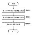
成否判定部150は、3次元形状モデルと、ステップS1100で取得された位置姿勢と、距離画像とに基づいて、組み付け成否を判定する。成否判定部150の判定結果は不図示の表示部等を介して出力される。出力の方法は表示に限らず、発光部や音源等を通じて成否を報知できれば何れの方法であってもよい。表示部、発光部、音源等の構成は情報処理装置1が備えていてもよいし、情報処理装置1とは別体の外部装置が備えていてもよい。以下、図6のフローチャートを参照して、ステップS1200における組み付け成否判定処理について詳述する。
(Step S1200)
The success /
(ステップS1210)
まず、評価値取得部140は、3次元形状モデル中から、組み付け元部品10に属する各局所面特徴を参照して、各面と距離画像中の3次元点との残差を算出し、この残差の平均値を組み付け元部品10の評価値として算出する。
(Step S1210)
First, the evaluation
(ステップS1220)
次に、評価値取得部140は、3次元形状モデル中から、組み付け先部品20に属する各局所面特徴を参照して、各面と距離画像中の3次元点との残差を算出し、この残差の平均値を組み付け先部品20の評価値として算出する。
(Step S1220)
Next, the evaluation
(ステップS1230)
成否判定部150は、ステップS1210で算出した組み付け元部品10の評価値と、ステッS1220で算出した組み付け先部品20の評価値とに基づき、組み付け成否を判定する。具体的には、組み付け先部品20の評価値と、組み付け元部品10の評価値とを、所定の閾値と比較する。閾値の設定については後述するが、2つの評価値に対して共通の値を用いてもよいし、それぞれ別の値に設定してもよい。
(Step S1230)
The success /
ここで、2つの評価値のうち、少なくともいずれか一方の評価値が所定の閾値を超過する場合には組み付け失敗と判定する。逆に、2つの評価値が、いずれも所定の閾値以下である場合には成功と判定する。 Here, when at least one of the two evaluation values exceeds a predetermined threshold, it is determined that the assembly has failed. Conversely, if both of the two evaluation values are equal to or less than the predetermined threshold, it is determined that the evaluation is successful.
なお、閾値は、事前に設定しておく。具体的には、たとえば、組み付け先部品20と組み付け元部品10とが正しく組み付けられた部品を撮影した組み付け成功画像を用意する。そして、組み付け成功画像に対してステップS1000からステップS1200までの処理を行い、成功画像に対して算出された組み付け元部品10の評価値、および組み付け先部品20の評価値を、それぞれ閾値として設定する。このとき、算出された評価値をそのまま閾値として用いるのではなく、一定のバイアスを付加して、成否判定の厳しさを調整してもよい。あるいは任意の閾値をユーザが手動で設定してもよいし、このほかの方法であってもかまわない。
The threshold value is set in advance. Specifically, for example, an assembly success image obtained by photographing a component in which the
以上説明したように、本実施形態では、組み付け済部品の3次元形状モデルに対して、部位ごとに組み付け先部品、あるいは、組み付け元部品のいずれかの属性を付与しておき、各属性に対応した組み付けの評価値をそれぞれ算出して、各評価値を用いて組み付けの成否判定を行う。 As described above, in this embodiment, an attribute of either the assembly destination part or the assembly source part is assigned to each part of the three-dimensional shape model of the assembled part, and each attribute is supported. Each evaluation value of the assembly is calculated, and the success or failure of the assembly is determined using each evaluation value.
これにより、組み付け先部品、あるいは、組み付け元部品の少なくとも一方の部品で撮影画像との不一致を検出できるため、着目部位の設定を行うことなく、且つ、組み付け済部品を構成する2部品の相対的な大きさ、形状、観測視点などの影響を受けずに、組み付けの成否を精度よく判定することが可能となる。 Thereby, since it is possible to detect a mismatch with the photographed image in at least one of the assembly destination component and the assembly source component, the relative positions of the two components constituting the assembled component can be determined without setting the target region. It is possible to accurately determine the success or failure of assembly without being affected by the size, shape, observation viewpoint, and the like.
なお、本実施形態では、評価値取得部140が算出する評価値として、各局所面特徴の平均値を用いたが、中央値を用いてもよいし、あるいは、各局所面特徴に対して算出した残差からヒストグラムを作成し、その最頻値を用いてもよい。また、本実施形態では、局所面特徴を利用して、各面と3次元点との残差を算出したが、局所線特徴を利用してもよい。その他、組み付け評価値の算出に使用する残差やその統計量の計算は、3次元形状モデルと撮影画像との差が検出できる限り、計算方式に特に制限はない。
In this embodiment, the average value of each local surface feature is used as the evaluation value calculated by the evaluation
(変形例1−1)
上述の実施形態では、2つの部品から構成される組み付け済部品を対象とした事例について述べた。しかし、3つ以上の部品で構成される組み付け済部品に対して、組み付けの成否を判定する場合にも同様の方法を適用可能である。この場合にも、組み付け済部品を構成する部品の属性を、組み付け済部品の3次元形状モデルの各形状にそれぞれ付与しておく。そして、3次元形状モデルの属性に基づき、その属性に該当する部位を参照してそれぞれ評価値を算出する。
(Modification 1-1)
In the above-described embodiment, an example has been described in which an assembled part composed of two parts is targeted. However, the same method can also be applied when determining the success or failure of assembly for an assembled component composed of three or more components. Also in this case, the attributes of the parts constituting the assembled parts are given to the respective shapes of the three-dimensional shape model of the assembled parts. Then, based on the attribute of the three-dimensional shape model, the evaluation value is calculated with reference to the part corresponding to the attribute.
構成部品のいずれか1つでも評価値が閾値よりも大きければ組み付け失敗、そうでなければ成功と判定する。これにより、3つ以上の部品で構成される組み付け済部品に対しても、着目部位の設定を行うことなく、組み付けの成否を精度よく判定することが可能となる。 If any one of the component parts has an evaluation value larger than the threshold value, it is determined that the assembly has failed. As a result, it is possible to accurately determine the success / failure of the assembly without setting the target part even for the assembled components composed of three or more components.
(第2の実施形態)
第1の実施形態では、複数部品から構成される組み付け済部品の組み付け成否を判定する行う方法について述べた。これに対して、本実施形態では、ロボットハンドにより把持を行った部品(把持部品)の画像を、ハンドに取り付けた撮影装置で撮影して把持の成否を判定することを想定する。なお、撮影装置はハンドに取り付けず、ロボットの動作範囲内に固定で設置したものを用いてもよい。このとき、ハンドによる隠蔽の影響を受けずに安定的に位置姿勢を算出する例を説明する。
(Second Embodiment)
In the first embodiment, the method for determining whether or not an assembled part composed of a plurality of parts is assembled has been described. In contrast, in the present embodiment, it is assumed that an image of a component (gripped component) gripped by the robot hand is captured by a photographing device attached to the hand and the success or failure of the grip is determined. In addition, you may use what was fixedly installed in the operation | movement range of the robot, without attaching an imaging device to a hand. At this time, an example in which the position and orientation are stably calculated without being affected by the concealment by the hand will be described.
図7に一例を示すような、ロボットアーム700の先端にロボットハンド710を取り付け、ロボットハンド710により把持した把持部品720を、ロボットハンドに取り付けた撮影装置730で撮影して、把持の成否を判定することを想定する。
As shown in FIG. 7, a
本実施形態では、正しく把持が行えた状態の、ロボットハンド710と把持部品720とを一体とみなした3次元形状モデル(以後、把持状態3次元形状モデルと呼ぶことにする)を利用する。ここで、把持状態3次元形状モデルには、ロボットハンド710に相当する部位と、把持部品720に相当する部位とを区別可能な属性を付与しておくものとする。この把持状態3次元形状モデルを、第1の実施形態における組み付け済部品30の3次元形状モデルとみなして、同様の処理を実施する。
In the present embodiment, a three-dimensional shape model (hereinafter, referred to as a gripping state three-dimensional shape model) in which the
すなわち、把持状態のロボットハンド710および把持部品720を一体のものとみなして、撮影画像を用いて位置姿勢を算出し、その後、把持状態3次元形状モデルから各属性に該当する部位を参照して、撮影画像との残差を求める。もし、ロボットハンド710に相当する部位、あるいは把持部品720に相当する部位のいずれかで残差が大きい場合には、把持に失敗していると判定し、そうでなければ把持に成功していると判定する。
That is, the
本実施形態によれば、ロボットハンドによる部品の把持の成否を、着目部位の設定を行うことなく精度よく判定することが可能となる。 According to the present embodiment, it is possible to accurately determine the success or failure of the gripping of the part by the robot hand without setting the region of interest.
(その他の実施形態)
本発明は、上述の実施形態の1以上の機能を実現するプログラムを、ネットワーク又は記憶媒体を介してシステム又は装置に供給し、そのシステム又は装置のコンピュータにおける1つ以上のプロセッサがプログラムを読出し実行する処理でも実現可能である。また、1以上の機能を実現する回路(例えば、ASIC)によっても実現可能である。
(Other embodiments)
The present invention supplies a program that realizes one or more functions of the above-described embodiments to a system or apparatus via a network or a storage medium, and one or more processors in the computer of the system or apparatus read and execute the program This process can be realized. It can also be realized by a circuit (for example, ASIC) that realizes one or more functions.
1:情報処理装置、10:組み付け元部品、20:組み付け先部品、30:組み付け済部品、110:モデル取得部、120:画像取得部、130:位置姿勢取得部、140:評価値取得部、150:成否判定部 1: information processing apparatus, 10: assembly source part, 20: assembly destination part, 30: assembled part, 110: model acquisition unit, 120: image acquisition unit, 130: position and orientation acquisition unit, 140: evaluation value acquisition unit, 150: Success / failure determination unit
Claims (11)
1以上の部位に前記第1の物体又は前記第2の物体の属性が付与された前記組み付け済物体の3次元形状モデルを取得するモデル取得手段と、
前記画像に基づいて前記組み付け済物体の位置姿勢を取得する位置姿勢取得手段と、
前記位置姿勢の前記3次元形状モデルの、前記第1の物体に相当する部位について組み付けの状態を評価するための第1の評価値と、前記第2の物体に相当する部位について組み付けの状態を評価するための第2の評価値とを取得する評価値取得手段と、
前記第1の評価値及び前記第2の評価値に基づいて組み付けの成否を判定する判定手段と、
を備えることを特徴とする情報処理装置。 Image acquisition means for acquiring an image of an assembled object in which the first object is assembled to the second object;
Model acquisition means for acquiring a three-dimensional shape model of the assembled object in which the attribute of the first object or the second object is given to one or more parts;
Position and orientation acquisition means for acquiring the position and orientation of the assembled object based on the image;
A first evaluation value for evaluating an assembly state of a part corresponding to the first object of the three-dimensional shape model of the position and orientation, and an assembly state of a part corresponding to the second object. Evaluation value acquisition means for acquiring a second evaluation value for evaluation;
Determining means for determining success or failure of assembly based on the first evaluation value and the second evaluation value;
An information processing apparatus comprising:
前記位置姿勢の前記3次元形状モデルの前記第1の物体に相当する部位の幾何特徴と、前記画像とから取得される第1の残差に基づいて、前記第1の評価値を取得し、
前記位置姿勢の前記3次元形状モデルの前記第2の物体に相当する部位の幾何特徴と、前記画像とから取得される第2の残差に基づいて、前記第2の評価値を取得する
ことを特徴とする請求項1乃至3の何れか1項に記載の情報処理装置。 The evaluation value acquisition means includes
Obtaining the first evaluation value based on a first residual obtained from a geometric feature of the part corresponding to the first object of the three-dimensional shape model of the position and orientation and the image;
Obtaining the second evaluation value on the basis of a second residual obtained from a geometric feature of the part corresponding to the second object of the three-dimensional shape model of the position and orientation and the image; The information processing apparatus according to any one of claims 1 to 3.
画像取得手段が、第1の物体が第2の物体に組み付けられた組み付け済物体の画像を取得する画像取得工程と、
モデル取得手段が、1以上の部位に前記第1の物体又は前記第2の物体の属性が付与された前記組み付け済物体の3次元形状モデルを取得するモデル取得工程と、
位置姿勢取得手段が、前記画像に基づいて前記組み付け済物体の位置姿勢を取得する位置姿勢取得工程と、
評価値取得手段が、前記位置姿勢の前記3次元形状モデルの、前記第1の物体に相当する部位について組み付けの状態を評価するための第1の評価値と、前記第2の物体に相当する部位について組み付けの状態を評価するための第2の評価値とを取得する評価値取得工程と、
判定手段が、前記第1の評価値及び前記第2の評価値に基づいて組み付けの成否を判定する判定工程と、
を有することを特徴とする情報処理装置の制御方法。 A method for controlling an information processing apparatus,
An image acquisition step of acquiring an image of an assembled object in which the first object is assembled to the second object;
A model acquisition step in which a model acquisition unit acquires a three-dimensional shape model of the assembled object in which the attribute of the first object or the second object is given to one or more parts;
A position and orientation acquisition step in which a position and orientation acquisition means acquires the position and orientation of the assembled object based on the image;
The evaluation value acquisition means corresponds to the first evaluation value for evaluating the assembly state of the part corresponding to the first object of the three-dimensional shape model of the position and orientation, and the second object. An evaluation value acquisition step of acquiring a second evaluation value for evaluating the assembly state of the part;
A determination step for determining whether the assembly is successful based on the first evaluation value and the second evaluation value;
A method for controlling an information processing apparatus, comprising:
Priority Applications (2)
| Application Number | Priority Date | Filing Date | Title |
|---|---|---|---|
| JP2016026347A JP6677522B2 (en) | 2016-02-15 | 2016-02-15 | Information processing apparatus, control method for information processing apparatus, and program |
| US15/429,868 US10242438B2 (en) | 2016-02-15 | 2017-02-10 | Information processing apparatus, control method of information processing apparatus, and storage medium for image recognition of the assembly of an object |
Applications Claiming Priority (1)
| Application Number | Priority Date | Filing Date | Title |
|---|---|---|---|
| JP2016026347A JP6677522B2 (en) | 2016-02-15 | 2016-02-15 | Information processing apparatus, control method for information processing apparatus, and program |
Publications (2)
| Publication Number | Publication Date |
|---|---|
| JP2017144498A true JP2017144498A (en) | 2017-08-24 |
| JP6677522B2 JP6677522B2 (en) | 2020-04-08 |
Family
ID=59562238
Family Applications (1)
| Application Number | Title | Priority Date | Filing Date |
|---|---|---|---|
| JP2016026347A Active JP6677522B2 (en) | 2016-02-15 | 2016-02-15 | Information processing apparatus, control method for information processing apparatus, and program |
Country Status (2)
| Country | Link |
|---|---|
| US (1) | US10242438B2 (en) |
| JP (1) | JP6677522B2 (en) |
Cited By (3)
| Publication number | Priority date | Publication date | Assignee | Title |
|---|---|---|---|---|
| JP2021007993A (en) * | 2019-06-28 | 2021-01-28 | 三菱電機株式会社 | Robot system, method of assembling assembly, assembly inspection method, motor-driven hand inspection method and motor-driven hand performance inspection jig |
| WO2021250923A1 (en) * | 2020-06-09 | 2021-12-16 | 株式会社日立産機システム | Robot system, control device, and control method |
| WO2024048426A1 (en) * | 2022-08-29 | 2024-03-07 | リンクウィズ株式会社 | Manufacturing system, control method, and control program |
Families Citing this family (5)
| Publication number | Priority date | Publication date | Assignee | Title |
|---|---|---|---|---|
| US10252417B2 (en) | 2016-03-02 | 2019-04-09 | Canon Kabushiki Kaisha | Information processing apparatus, method of controlling information processing apparatus, and storage medium |
| JP6850639B2 (en) * | 2017-03-09 | 2021-03-31 | 本田技研工業株式会社 | robot |
| CN110740841B (en) * | 2017-06-13 | 2023-10-27 | 川崎重工业株式会社 | Operating system |
| US10682774B2 (en) * | 2017-12-12 | 2020-06-16 | X Development Llc | Sensorized robotic gripping device |
| US11816798B1 (en) * | 2020-03-17 | 2023-11-14 | Apple Inc. | 3D surface representation refinement |
Citations (6)
| Publication number | Priority date | Publication date | Assignee | Title |
|---|---|---|---|---|
| US4402053A (en) * | 1980-09-25 | 1983-08-30 | Board Of Regents For Education For The State Of Rhode Island | Estimating workpiece pose using the feature points method |
| JP2000055637A (en) * | 1998-08-10 | 2000-02-25 | Mazda Motor Corp | Work inspecting device, part image generating device, work inspecting method, and computor-readable storage medium |
| JP2004358557A (en) * | 2001-11-05 | 2004-12-24 | Citizen Watch Co Ltd | Assembling machine and assembling method |
| JP2005147974A (en) * | 2003-11-19 | 2005-06-09 | Daihatsu Motor Co Ltd | Device for inspecting erroneous/missing product |
| JP2007268683A (en) * | 2006-03-31 | 2007-10-18 | Shigeru Co Ltd | Erroneous assembling preventive method for component |
| JP2015114722A (en) * | 2013-12-09 | 2015-06-22 | キヤノン株式会社 | Information processing apparatus, control method thereof, information processing system, and program |
Family Cites Families (10)
| Publication number | Priority date | Publication date | Assignee | Title |
|---|---|---|---|---|
| JP5393318B2 (en) * | 2009-07-28 | 2014-01-22 | キヤノン株式会社 | Position and orientation measurement method and apparatus |
| JP5618569B2 (en) * | 2010-02-25 | 2014-11-05 | キヤノン株式会社 | Position and orientation estimation apparatus and method |
| JP5746477B2 (en) * | 2010-02-26 | 2015-07-08 | キヤノン株式会社 | Model generation device, three-dimensional measurement device, control method thereof, and program |
| JP5863440B2 (en) * | 2010-12-28 | 2016-02-16 | キヤノン株式会社 | Information processing apparatus and method |
| JP6323993B2 (en) * | 2012-08-28 | 2018-05-16 | キヤノン株式会社 | Information processing apparatus, information processing method, and computer program |
| JP6370038B2 (en) * | 2013-02-07 | 2018-08-08 | キヤノン株式会社 | Position and orientation measurement apparatus and method |
| JP6324025B2 (en) * | 2013-11-05 | 2018-05-16 | キヤノン株式会社 | Information processing apparatus and information processing method |
| JP6594129B2 (en) * | 2014-11-28 | 2019-10-23 | キヤノン株式会社 | Information processing apparatus, information processing method, and program |
| JP2016170122A (en) * | 2015-03-13 | 2016-09-23 | キヤノン株式会社 | Measurement device |
| US20180029235A1 (en) * | 2016-07-28 | 2018-02-01 | X Development Llc | Error Accrual and Mitigation During Robotic Process |
-
2016
- 2016-02-15 JP JP2016026347A patent/JP6677522B2/en active Active
-
2017
- 2017-02-10 US US15/429,868 patent/US10242438B2/en active Active
Patent Citations (6)
| Publication number | Priority date | Publication date | Assignee | Title |
|---|---|---|---|---|
| US4402053A (en) * | 1980-09-25 | 1983-08-30 | Board Of Regents For Education For The State Of Rhode Island | Estimating workpiece pose using the feature points method |
| JP2000055637A (en) * | 1998-08-10 | 2000-02-25 | Mazda Motor Corp | Work inspecting device, part image generating device, work inspecting method, and computor-readable storage medium |
| JP2004358557A (en) * | 2001-11-05 | 2004-12-24 | Citizen Watch Co Ltd | Assembling machine and assembling method |
| JP2005147974A (en) * | 2003-11-19 | 2005-06-09 | Daihatsu Motor Co Ltd | Device for inspecting erroneous/missing product |
| JP2007268683A (en) * | 2006-03-31 | 2007-10-18 | Shigeru Co Ltd | Erroneous assembling preventive method for component |
| JP2015114722A (en) * | 2013-12-09 | 2015-06-22 | キヤノン株式会社 | Information processing apparatus, control method thereof, information processing system, and program |
Cited By (5)
| Publication number | Priority date | Publication date | Assignee | Title |
|---|---|---|---|---|
| JP2021007993A (en) * | 2019-06-28 | 2021-01-28 | 三菱電機株式会社 | Robot system, method of assembling assembly, assembly inspection method, motor-driven hand inspection method and motor-driven hand performance inspection jig |
| JP7080203B2 (en) | 2019-06-28 | 2022-06-03 | 三菱電機株式会社 | Robot system, assembly method, assembly inspection method, electric hand inspection method and electric hand performance inspection jig |
| WO2021250923A1 (en) * | 2020-06-09 | 2021-12-16 | 株式会社日立産機システム | Robot system, control device, and control method |
| JP7479205B2 (en) | 2020-06-09 | 2024-05-08 | 株式会社日立オートメーション | ROBOT SYSTEM, CONTROL DEVICE, AND CONTROL METHOD |
| WO2024048426A1 (en) * | 2022-08-29 | 2024-03-07 | リンクウィズ株式会社 | Manufacturing system, control method, and control program |
Also Published As
| Publication number | Publication date |
|---|---|
| US10242438B2 (en) | 2019-03-26 |
| US20170236268A1 (en) | 2017-08-17 |
| JP6677522B2 (en) | 2020-04-08 |
Similar Documents
| Publication | Publication Date | Title |
|---|---|---|
| JP6444027B2 (en) | Information processing apparatus, information processing apparatus control method, information processing system, and program | |
| US11911914B2 (en) | System and method for automatic hand-eye calibration of vision system for robot motion | |
| JP6677522B2 (en) | Information processing apparatus, control method for information processing apparatus, and program | |
| JP5393318B2 (en) | Position and orientation measurement method and apparatus | |
| JP6180087B2 (en) | Information processing apparatus and information processing method | |
| JP6324025B2 (en) | Information processing apparatus and information processing method | |
| JP5839971B2 (en) | Information processing apparatus, information processing method, and program | |
| JP5567908B2 (en) | Three-dimensional measuring apparatus, measuring method and program | |
| JP6021533B2 (en) | Information processing system, apparatus, method, and program | |
| JP6092530B2 (en) | Image processing apparatus and image processing method | |
| JP6370038B2 (en) | Position and orientation measurement apparatus and method | |
| US20130108116A1 (en) | Position/orientation measurement apparatus, measurement processing method thereof, and non-transitory computer-readable storage medium | |
| JP6317618B2 (en) | Information processing apparatus and method, measuring apparatus, and working apparatus | |
| JP2012123781A (en) | Information processing device, information processing system and information processing method | |
| JP2016170050A (en) | Position attitude measurement device, position attitude measurement method and computer program | |
| JP6626338B2 (en) | Information processing apparatus, control method for information processing apparatus, and program | |
| US10252417B2 (en) | Information processing apparatus, method of controlling information processing apparatus, and storage medium | |
| JP6180158B2 (en) | Position / orientation measuring apparatus, control method and program for position / orientation measuring apparatus | |
| JP6040264B2 (en) | Information processing apparatus, information processing apparatus control method, and program | |
| JP6890422B2 (en) | Information processing equipment, control methods and programs for information processing equipment | |
| JP6285765B2 (en) | Information processing apparatus and information processing method | |
| JP6766229B2 (en) | Position and posture measuring device and method |
Legal Events
| Date | Code | Title | Description |
|---|---|---|---|
| A621 | Written request for application examination |
Free format text: JAPANESE INTERMEDIATE CODE: A621 Effective date: 20190212 |
|
| A977 | Report on retrieval |
Free format text: JAPANESE INTERMEDIATE CODE: A971007 Effective date: 20190912 |
|
| A131 | Notification of reasons for refusal |
Free format text: JAPANESE INTERMEDIATE CODE: A131 Effective date: 20191004 |
|
| A521 | Request for written amendment filed |
Free format text: JAPANESE INTERMEDIATE CODE: A523 Effective date: 20191202 |
|
| TRDD | Decision of grant or rejection written | ||
| A01 | Written decision to grant a patent or to grant a registration (utility model) |
Free format text: JAPANESE INTERMEDIATE CODE: A01 Effective date: 20200214 |
|
| A61 | First payment of annual fees (during grant procedure) |
Free format text: JAPANESE INTERMEDIATE CODE: A61 Effective date: 20200313 |
|
| R151 | Written notification of patent or utility model registration |
Ref document number: 6677522 Country of ref document: JP Free format text: JAPANESE INTERMEDIATE CODE: R151 |