JP2017135218A - Charged particle beam lens device, charged particle beam column, and charged particle beam exposure device - Google Patents

Charged particle beam lens device, charged particle beam column, and charged particle beam exposure device Download PDF

Info

Publication number
JP2017135218A
JP2017135218A JP2016012798A JP2016012798A JP2017135218A JP 2017135218 A JP2017135218 A JP 2017135218A JP 2016012798 A JP2016012798 A JP 2016012798A JP 2016012798 A JP2016012798 A JP 2016012798A JP 2017135218 A JP2017135218 A JP 2017135218A
Authority
JP
Japan
Prior art keywords
lens
charged particle
particle beam
electron beam
groove
Prior art date
Legal status (The legal status is an assumption and is not a legal conclusion. Google has not performed a legal analysis and makes no representation as to the accuracy of the status listed.)
Withdrawn
Application number
JP2016012798A
Other languages
Japanese (ja)
Inventor
阿部 智彦
Tomohiko Abe
智彦 阿部
小島 真一
Shinichi Kojima
真一 小島
Current Assignee (The listed assignees may be inaccurate. Google has not performed a legal analysis and makes no representation or warranty as to the accuracy of the list.)
Advantest Corp
Original Assignee
Advantest Corp
Priority date (The priority date is an assumption and is not a legal conclusion. Google has not performed a legal analysis and makes no representation as to the accuracy of the date listed.)
Filing date
Publication date
Application filed by Advantest Corp filed Critical Advantest Corp
Priority to JP2016012798A priority Critical patent/JP2017135218A/en
Priority to EP16195044.9A priority patent/EP3200216A1/en
Priority to TW107123125A priority patent/TW201907435A/en
Priority to TW105134224A priority patent/TWI632586B/en
Priority to KR1020160141442A priority patent/KR101877633B1/en
Priority to US15/335,448 priority patent/US10049854B2/en
Priority to CN201610958663.3A priority patent/CN107017142A/en
Publication of JP2017135218A publication Critical patent/JP2017135218A/en
Withdrawn legal-status Critical Current

Links

Images

Classifications

    • HELECTRICITY
    • H01ELECTRIC ELEMENTS
    • H01JELECTRIC DISCHARGE TUBES OR DISCHARGE LAMPS
    • H01J37/00Discharge tubes with provision for introducing objects or material to be exposed to the discharge, e.g. for the purpose of examination or processing thereof
    • H01J37/02Details
    • H01J37/04Arrangements of electrodes and associated parts for generating or controlling the discharge, e.g. electron-optical arrangement, ion-optical arrangement
    • H01J37/10Lenses
    • H01J37/14Lenses magnetic
    • GPHYSICS
    • G03PHOTOGRAPHY; CINEMATOGRAPHY; ANALOGOUS TECHNIQUES USING WAVES OTHER THAN OPTICAL WAVES; ELECTROGRAPHY; HOLOGRAPHY
    • G03FPHOTOMECHANICAL PRODUCTION OF TEXTURED OR PATTERNED SURFACES, e.g. FOR PRINTING, FOR PROCESSING OF SEMICONDUCTOR DEVICES; MATERIALS THEREFOR; ORIGINALS THEREFOR; APPARATUS SPECIALLY ADAPTED THEREFOR
    • G03F7/00Photomechanical, e.g. photolithographic, production of textured or patterned surfaces, e.g. printing surfaces; Materials therefor, e.g. comprising photoresists; Apparatus specially adapted therefor
    • G03F7/70Microphotolithographic exposure; Apparatus therefor
    • G03F7/70216Mask projection systems
    • G03F7/70275Multiple projection paths, e.g. array of projection systems, microlens projection systems or tandem projection systems
    • HELECTRICITY
    • H01ELECTRIC ELEMENTS
    • H01JELECTRIC DISCHARGE TUBES OR DISCHARGE LAMPS
    • H01J37/00Discharge tubes with provision for introducing objects or material to be exposed to the discharge, e.g. for the purpose of examination or processing thereof
    • H01J37/02Details
    • H01J37/04Arrangements of electrodes and associated parts for generating or controlling the discharge, e.g. electron-optical arrangement, ion-optical arrangement
    • H01J37/10Lenses
    • H01J37/14Lenses magnetic
    • H01J37/141Electromagnetic lenses
    • GPHYSICS
    • G03PHOTOGRAPHY; CINEMATOGRAPHY; ANALOGOUS TECHNIQUES USING WAVES OTHER THAN OPTICAL WAVES; ELECTROGRAPHY; HOLOGRAPHY
    • G03FPHOTOMECHANICAL PRODUCTION OF TEXTURED OR PATTERNED SURFACES, e.g. FOR PRINTING, FOR PROCESSING OF SEMICONDUCTOR DEVICES; MATERIALS THEREFOR; ORIGINALS THEREFOR; APPARATUS SPECIALLY ADAPTED THEREFOR
    • G03F1/00Originals for photomechanical production of textured or patterned surfaces, e.g., masks, photo-masks, reticles; Mask blanks or pellicles therefor; Containers specially adapted therefor; Preparation thereof
    • G03F1/20Masks or mask blanks for imaging by charged particle beam [CPB] radiation, e.g. by electron beam; Preparation thereof
    • GPHYSICS
    • G03PHOTOGRAPHY; CINEMATOGRAPHY; ANALOGOUS TECHNIQUES USING WAVES OTHER THAN OPTICAL WAVES; ELECTROGRAPHY; HOLOGRAPHY
    • G03FPHOTOMECHANICAL PRODUCTION OF TEXTURED OR PATTERNED SURFACES, e.g. FOR PRINTING, FOR PROCESSING OF SEMICONDUCTOR DEVICES; MATERIALS THEREFOR; ORIGINALS THEREFOR; APPARATUS SPECIALLY ADAPTED THEREFOR
    • G03F7/00Photomechanical, e.g. photolithographic, production of textured or patterned surfaces, e.g. printing surfaces; Materials therefor, e.g. comprising photoresists; Apparatus specially adapted therefor
    • G03F7/70Microphotolithographic exposure; Apparatus therefor
    • G03F7/708Construction of apparatus, e.g. environment aspects, hygiene aspects or materials
    • G03F7/70808Construction details, e.g. housing, load-lock, seals or windows for passing light in or out of apparatus
    • G03F7/70833Mounting of optical systems, e.g. mounting of illumination system, projection system or stage systems on base-plate or ground
    • HELECTRICITY
    • H01ELECTRIC ELEMENTS
    • H01JELECTRIC DISCHARGE TUBES OR DISCHARGE LAMPS
    • H01J37/00Discharge tubes with provision for introducing objects or material to be exposed to the discharge, e.g. for the purpose of examination or processing thereof
    • H01J37/02Details
    • H01J37/04Arrangements of electrodes and associated parts for generating or controlling the discharge, e.g. electron-optical arrangement, ion-optical arrangement
    • H01J37/06Electron sources; Electron guns
    • H01J37/07Eliminating deleterious effects due to thermal effects or electric or magnetic fields
    • HELECTRICITY
    • H01ELECTRIC ELEMENTS
    • H01JELECTRIC DISCHARGE TUBES OR DISCHARGE LAMPS
    • H01J37/00Discharge tubes with provision for introducing objects or material to be exposed to the discharge, e.g. for the purpose of examination or processing thereof
    • H01J37/30Electron-beam or ion-beam tubes for localised treatment of objects
    • H01J37/317Electron-beam or ion-beam tubes for localised treatment of objects for changing properties of the objects or for applying thin layers thereon, e.g. for ion implantation
    • H01J37/3174Particle-beam lithography, e.g. electron beam lithography
    • H01J37/3177Multi-beam, e.g. fly's eye, comb probe
    • HELECTRICITY
    • H01ELECTRIC ELEMENTS
    • H01JELECTRIC DISCHARGE TUBES OR DISCHARGE LAMPS
    • H01J2237/00Discharge tubes exposing object to beam, e.g. for analysis treatment, etching, imaging
    • H01J2237/002Cooling arrangements
    • HELECTRICITY
    • H01ELECTRIC ELEMENTS
    • H01JELECTRIC DISCHARGE TUBES OR DISCHARGE LAMPS
    • H01J2237/00Discharge tubes exposing object to beam, e.g. for analysis treatment, etching, imaging
    • H01J2237/10Lenses
    • H01J2237/14Lenses magnetic
    • H01J2237/1405Constructional details
    • HELECTRICITY
    • H01ELECTRIC ELEMENTS
    • H01JELECTRIC DISCHARGE TUBES OR DISCHARGE LAMPS
    • H01J2237/00Discharge tubes exposing object to beam, e.g. for analysis treatment, etching, imaging
    • H01J2237/20Positioning, supporting, modifying or maintaining the physical state of objects being observed or treated
    • H01J2237/202Movement
    • H01J2237/20278Motorised movement
    • H01J2237/20285Motorised movement computer-controlled
    • HELECTRICITY
    • H01ELECTRIC ELEMENTS
    • H01JELECTRIC DISCHARGE TUBES OR DISCHARGE LAMPS
    • H01J2237/00Discharge tubes exposing object to beam, e.g. for analysis treatment, etching, imaging
    • H01J2237/30Electron or ion beam tubes for processing objects
    • H01J2237/317Processing objects on a microscale
    • H01J2237/3175Lithography
    • H01J2237/31774Multi-beam

Landscapes

  • Chemical & Material Sciences (AREA)
  • Analytical Chemistry (AREA)
  • Physics & Mathematics (AREA)
  • General Physics & Mathematics (AREA)
  • Electromagnetism (AREA)
  • Health & Medical Sciences (AREA)
  • Engineering & Computer Science (AREA)
  • Environmental & Geological Engineering (AREA)
  • Epidemiology (AREA)
  • Public Health (AREA)
  • Electron Beam Exposure (AREA)

Abstract

PROBLEM TO BE SOLVED: To provide a small size charged particle beam lens device of high resolution, and to provide a charged particle beam column and a charged particle beam exposure device.SOLUTION: A charged particle beam lens device includes: a lens 40 formed around a through hole for passing a charged particle beam, and focusing or diffusing the charged particle beam; and a support 50 surrounding the outer periphery of the lens 40. At least one of the outer peripheral part of the lens 40 in contact with the support 50 and the inner peripheral part of the support 50 in contact with the lens 40, has a groove 61 for feeding a cooling fluid along the outer periphery of the lens. With such an arrangement, a small size charged particle beam lens device of high resolution can be provided.SELECTED DRAWING: Figure 2B

Description

本発明は、荷電粒子ビームレンズ装置、荷電粒子ビームカラム、および荷電粒子ビーム露光装置に関する。   The present invention relates to a charged particle beam lens apparatus, a charged particle beam column, and a charged particle beam exposure apparatus.

従来、光露光技術で形成したラインパターンを、電子ビーム等の荷電粒子ビームを用いて加工するコンプリメンタリ・リソグラフィが知られている(例えば、特許文献1参照)。また、荷電粒子ビームレンズを有する荷電粒子ビームカラムを複数個並べた荷電粒子ビーム露光装置が知られている(例えば、非特許文献1参照)。また、荷電粒子ビームレンズの排熱手段も知られている(例えば、特許文献2、3参照)。
特許文献1 特開2013−16744号公報
特許文献2 特開昭61−227356号公報
特許文献3 特開2014−120545号公報
非特許文献1 Proc. SPIE 7637, Alternative Lithographic Technologies II, 76370C (March 10, 2010).
Conventionally, complementary lithography is known in which a line pattern formed by an optical exposure technique is processed using a charged particle beam such as an electron beam (see, for example, Patent Document 1). There is also known a charged particle beam exposure apparatus in which a plurality of charged particle beam columns each having a charged particle beam lens are arranged (see, for example, Non-Patent Document 1). In addition, exhaust heat means for charged particle beam lenses is also known (see, for example, Patent Documents 2 and 3).
Patent Document 1 JP 2013-16744 JP Patent Document 2 JP 61-227356 JP Patent Document 3 JP 2014-120545 Non-Patent Document 1 Proc. SPIE 7637, Alternative Lithographic Technologies II, 76370C (March 10, 2010).

このような露光装置は、荷電粒子ビームカラムを複数並べるので、レンズの大きさに制限があり、ビーム電流値を維持しながら高い解像性を得ることが困難であった。荷電粒子ビームレンズの励磁電流を増加して強く励磁すると、高い解像度が得られるが、荷電粒子ビームレンズの発熱が大きくなってしまい、当該発熱の対策として荷電粒子ビームレンズに排熱等の機構を設けると、荷電粒子ビームレンズが大型化してしまうからである。このため、小型で解像度の高い荷電粒子ビームレンズが望まれていた。   In such an exposure apparatus, since a plurality of charged particle beam columns are arranged, the size of the lens is limited, and it is difficult to obtain high resolution while maintaining the beam current value. When the excitation current of the charged particle beam lens is increased and excited strongly, a high resolution can be obtained. However, the charged particle beam lens generates a large amount of heat, and a mechanism such as exhaust heat is added to the charged particle beam lens as a countermeasure against the heat generation. This is because the provision of the charged particle beam lens increases in size. For this reason, a compact and high-resolution charged particle beam lens has been desired.

例えば、荷電粒子ビームレンズの排熱手段として、二重構造を有する部材を導入し、その間隙に冷却用液体を流す手段(例えば、特許文献2参照)、および励磁部を封じ込めた容器を設け、その内部に冷却用液体を流す手段(例えば、特許文献3参照)などが提案されている。しかし、これらの手段は、荷電粒子ビームレンズに新たな部材を追加して冷却水流路を形成するため、荷電粒子ビームレンズの大きさは、その部材の幅の分だけ大きく変化していた。   For example, as a means for exhausting heat of a charged particle beam lens, a member having a double structure is introduced, a means for flowing a cooling liquid into the gap (see, for example, Patent Document 2), and a container containing an excitation unit are provided. Means (for example, refer to Patent Document 3) for causing a cooling liquid to flow therein has been proposed. However, since these means add a new member to the charged particle beam lens to form the cooling water flow path, the size of the charged particle beam lens has changed greatly by the width of the member.

本発明の第1の態様においては、荷電粒子ビームを通過させる貫通孔の周囲に形成され、荷電粒子ビームを収束または拡散させるレンズ部と、レンズ部の外周を囲む支持部と、を備え、レンズ部における支持部と接する外周部分および支持部におけるレンズ部と接する内周部分の少なくとも一方は、レンズ部の外周に沿って冷却用流体を流すための溝部を有する荷電粒子ビームレンズ装置を提供する。   In a first aspect of the present invention, the lens includes a lens unit that is formed around a through-hole that allows the charged particle beam to pass therethrough and converges or diffuses the charged particle beam, and a support unit that surrounds the outer periphery of the lens unit. At least one of the outer peripheral portion in contact with the support portion in the portion and the inner peripheral portion in contact with the lens portion in the support portion provides a charged particle beam lens device having a groove portion for flowing a cooling fluid along the outer periphery of the lens portion.

本発明の第2の態様においては、荷電粒子ビームを通過させる貫通孔の周囲に形成され、荷電粒子ビームを収束または拡散させるレンズ部と、レンズ部の外周を囲む支持部と、を備え、レンズ部は、貫通孔の周囲に形成される第1部材と、第1部材の外周を囲む第2部材と、を有し、第1部材における第2部材と接する外周部分および第2部材における第1部材と接する内周部分の少なくとも一方は、第1部材の外周に沿って冷却用流体を流すための溝部を有する荷電粒子ビームレンズ装置を提供する。   In a second aspect of the present invention, the lens includes a lens unit that is formed around a through-hole that allows the charged particle beam to pass therethrough, and converges or diffuses the charged particle beam, and a support unit that surrounds the outer periphery of the lens unit. The portion includes a first member formed around the through hole, and a second member surrounding the outer periphery of the first member, and the outer peripheral portion of the first member in contact with the second member and the first member of the second member. At least one of the inner peripheral portions in contact with the member provides a charged particle beam lens device having a groove for flowing a cooling fluid along the outer periphery of the first member.

本発明の第3の態様においては、荷電粒子ビームを放出する粒子源と、第1の態様および第2の態様のいずれかの荷電粒子ビームレンズ装置と、を有する荷電粒子ビームカラムを提供する。   According to a third aspect of the present invention, there is provided a charged particle beam column having a particle source that emits a charged particle beam and the charged particle beam lens device according to any one of the first and second aspects.

本実施形態に係る電子ビーム露光装置100の構成例を示す。1 shows a configuration example of an electron beam exposure apparatus 100 according to the present embodiment. 本実施形態に係る電子ビームレンズ装置30の構成例を示す斜視図である。It is a perspective view which shows the structural example of the electron beam lens apparatus 30 which concerns on this embodiment. 本実施形態に係る電子ビームレンズ装置30の構成例を示す断面図である。It is sectional drawing which shows the structural example of the electron beam lens apparatus 30 which concerns on this embodiment. 本実施形態に係るレンズ部40の第1の変形例を示す斜視図である。It is a perspective view which shows the 1st modification of the lens part 40 which concerns on this embodiment. 本実施形態に係るレンズ部40の第2の変形例を示す斜視図である。It is a perspective view which shows the 2nd modification of the lens part 40 which concerns on this embodiment. 本実施形態に係るレンズ部40の第3の変形例を示す斜視図である。It is a perspective view which shows the 3rd modification of the lens part 40 which concerns on this embodiment. 本実施形態に係るレンズ部40の第4の変形例を示す斜視図である。It is a perspective view which shows the 4th modification of the lens part 40 which concerns on this embodiment. 冷却水の流量と、溝部61の両端の圧力差および排水温度との関係を示すグラフである。It is a graph which shows the relationship between the flow volume of a cooling water, the pressure difference of the both ends of the groove part 61, and drainage temperature. 本実施形態に係る電子ビーム露光装置100の変形例を示す。The modification of the electron beam exposure apparatus 100 which concerns on this embodiment is shown. 電子ビーム露光装置100の変形例におけるレンズ部40の構成を示す断面図である。FIG. 6 is a cross-sectional view illustrating a configuration of a lens unit 40 in a modification of the electron beam exposure apparatus 100. 本実施形態に係るレンズ部40の第5の変形例を示す斜視図である。It is a perspective view which shows the 5th modification of the lens part 40 which concerns on this embodiment. 電子ビームレンズおよび排熱手段の第1の例を示す断面図である。It is sectional drawing which shows the 1st example of an electron beam lens and a waste heat means. 電子ビームレンズおよび排熱手段の第2の例を示す断面図である。It is sectional drawing which shows the 2nd example of an electron beam lens and a waste heat means. 電子ビームレンズおよび排熱手段の第3の例を示す断面図である。It is sectional drawing which shows the 3rd example of an electron beam lens and a heat exhausting means. 電子ビームレンズの球面収差係数Csと、電子ビームレンズの発熱量Qcとの関係を示すグラフである。It is a graph which shows the relationship between the spherical aberration coefficient Cs of an electron beam lens, and the emitted-heat amount Qc of an electron beam lens.

以下、発明の実施の形態を通じて本発明を説明するが、以下の実施形態は特許請求の範囲にかかる発明を限定するものではない。また、実施形態の中で説明されている特徴の組み合わせの全てが発明の解決手段に必須であるとは限らない。   Hereinafter, the present invention will be described through embodiments of the invention, but the following embodiments do not limit the invention according to the claims. In addition, not all the combinations of features described in the embodiments are essential for the solving means of the invention.

まず、電子ビームレンズのレンズ特性とレンズの発熱との関係、および電子ビームレンズの排熱手段、について説明する。   First, the relationship between the lens characteristics of the electron beam lens and the heat generation of the lens, and the heat discharging means of the electron beam lens will be described.

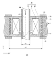
図11Aは、電子ビームレンズおよび排熱手段の第1の例を示す断面図である。図11Bは、電子ビームレンズおよび排熱手段の第2の例を示す断面図である。図11Cは、電子ビームレンズおよび排熱手段の第3の例を示す断面図である。それぞれの図において、電子ビームレンズを構成する部材は、Z軸に平行な一点鎖線で示された軸LAのまわりに軸対称に配置される。電子ビームレンズは、励磁部42と、磁性体部43と、ギャップ部44と、を備える。電子ビームは、一例として、対称軸LAに沿って、電子ビームレンズを通過する。励磁部42は、軸LAを巻線の中心軸とするコイルである。励磁部42は、軸LAのまわりに電流を流すことにより、軸LA上に軸LAの延伸方向の磁場を発生する。   FIG. 11A is a cross-sectional view showing a first example of an electron beam lens and heat exhausting means. FIG. 11B is a cross-sectional view illustrating a second example of the electron beam lens and the heat exhausting unit. FIG. 11C is a cross-sectional view illustrating a third example of the electron beam lens and the heat exhausting unit. In each figure, the members constituting the electron beam lens are arranged symmetrically about an axis LA indicated by a one-dot chain line parallel to the Z axis. The electron beam lens includes an exciting part 42, a magnetic part 43, and a gap part 44. As an example, the electron beam passes through the electron beam lens along the symmetry axis LA. The excitation unit 42 is a coil having the axis LA as the central axis of the winding. The excitation unit 42 generates a magnetic field in the extending direction of the axis LA on the axis LA by causing a current to flow around the axis LA.

磁性体部43は、励磁部42が励磁した磁場を、ギャップ部44付近に集中させる。これにより図11A、図11B、および図11Cはそれぞれ、軸LAをレンズ軸とする電子ビームレンズを構成する。幅d1は、レンズ軸LAに沿って電子ビームを通過させる電子ビームレンズの貫通孔の内径を示す。また、幅d2は、レンズ軸LAを中心軸として円柱形状を有す電子ビームレンズの外径を示す。   The magnetic part 43 concentrates the magnetic field excited by the excitation part 42 in the vicinity of the gap part 44. Accordingly, FIGS. 11A, 11B, and 11C each constitute an electron beam lens having the axis LA as a lens axis. The width d1 indicates the inner diameter of the through hole of the electron beam lens that allows the electron beam to pass along the lens axis LA. The width d2 indicates the outer diameter of the electron beam lens having a cylindrical shape with the lens axis LA as the central axis.

このような電子ビームレンズを対物レンズとする電子ビームカラムにおいて、レンズの解像性を決める基本的なパラメータである球面収差係数Csと、励磁部42のコイルに流す電流によって発生する発熱量Qcとの関係を検討した。なお、球面収差係数Csは、電子ビームレンズの収束半角をαとすると、Cs×αが当該電子ビームレンズの収差となる係数である。図12は、電子ビームレンズの球面収差係数Csと、電子ビームレンズの発熱量Qcとの関係を示すグラフである。図12は、横軸を球面収差係数Cs、縦軸を電子ビームレンズの発熱量Qcとする。図12は、励磁部42、磁性体部43、およびギャップ部44の形状および大きさを、より少ない発熱量Qcで、より小さい収差係数Csを得るように最適化して得られた、球面収差係数Csと発熱量Qcとの関係を示すグラフである。 In an electron beam column using such an electron beam lens as an objective lens, a spherical aberration coefficient Cs, which is a basic parameter for determining the resolution of the lens, and a calorific value Qc generated by a current flowing through the coil of the excitation unit 42, The relationship was examined. Incidentally, the spherical aberration coefficient Cs is the convergence half angle of the electron beam lens is alpha, a coefficient Cs × alpha 3 is aberration of the electron beam lens. FIG. 12 is a graph showing the relationship between the spherical aberration coefficient Cs of the electron beam lens and the calorific value Qc of the electron beam lens. In FIG. 12, the horizontal axis represents the spherical aberration coefficient Cs, and the vertical axis represents the calorific value Qc of the electron beam lens. FIG. 12 shows spherical aberration coefficients obtained by optimizing the shapes and sizes of the excitation part 42, the magnetic part 43, and the gap part 44 so as to obtain a smaller aberration coefficient Cs with a smaller calorific value Qc. It is a graph which shows the relationship between Cs and the emitted-heat amount Qc.

図12のグラフは、電子ビームの加速電圧が50KV、磁性体部43の内径d1がφ8mm、および磁性体部43の外径d2がφ28mmの条件で求めた例を示す。また、励磁部42のコイル巻線断面の動径方向の幅(一例として、図11Aにおけるd3)は4mm以内、磁性体部43の断面の動径方向の幅は、内側(レンズ軸LAに近い側、一例として、図11Aにおけるd4)および外側(レンズ軸LAから遠い側一例として、図11Aにおけるd5)ともに3mm以内という条件で求めた例を示す。   The graph of FIG. 12 shows an example in which the acceleration voltage of the electron beam is 50 KV, the inner diameter d1 of the magnetic body portion 43 is φ8 mm, and the outer diameter d2 of the magnetic body portion 43 is φ28 mm. In addition, the radial width (as an example, d3 in FIG. 11A) of the coil winding cross section of the excitation portion 42 is within 4 mm, and the radial width of the cross section of the magnetic body portion 43 is inside (close to the lens axis LA). As an example, an example is shown in which d4 in FIG. 11A) and outside (d5 in FIG. 11A as an example far side from the lens axis LA) are both determined to be within 3 mm.

図12は、電子ビームレンズのパラメータ毎に、発熱量Qcと球面収差係数Csとをシミュレーションにより算出して、プロットした例である。電子ビームレンズのパラメータは、励磁部42の巻線部分の断面形状およびZ軸方向の長さ、励磁部42を囲む磁性体部43の断面形状およびZ軸方向の長さ、ギャップ部44の位置および間隔、ならびにビームが出射する側のレンズの下面と試料上の結像面との間の間隔などである。なお、図12のグラフは、パラメータ毎のプロットの結果から、より少ない発熱量Qcで、より小さい収差係数Csが得られている点、即ち、縦軸および横軸により近い点、を繋いで作成した例を示す。   FIG. 12 is an example in which the calorific value Qc and the spherical aberration coefficient Cs are calculated by simulation and plotted for each parameter of the electron beam lens. The parameters of the electron beam lens include the cross-sectional shape and the length in the Z-axis direction of the winding portion of the excitation unit 42, the cross-sectional shape and the length in the Z-axis direction of the magnetic part 43 surrounding the excitation unit 42, and the position of the gap portion 44. And the distance, and the distance between the lower surface of the lens on the beam exit side and the imaging surface on the sample. The graph of FIG. 12 is created by connecting the points where the smaller heat generation amount Qc and the smaller aberration coefficient Cs are obtained from the plot results for each parameter, that is, the points closer to the vertical axis and the horizontal axis. An example is shown.

図12のグラフから、球面収差係数Csが5mm以下の電子ビームレンズの発熱量Qcは、100W以上であることが分かる。ここで、球面収差係数Csが5mm以下の条件は、電子ビームレンズによって、収束半角αが例えば10mradの範囲の電子ビームを収束した場合に、Cs×αで計算される収差が、例えば5nm以下となる条件を示す。 From the graph of FIG. 12, it can be seen that the calorific value Qc of the electron beam lens having the spherical aberration coefficient Cs of 5 mm or less is 100 W or more. Here, the condition that the spherical aberration coefficient Cs is 5 mm or less is that when the electron beam lens converges an electron beam with a convergence half angle α of, for example, 10 mrad, the aberration calculated by Cs × α 3 is, for example, 5 nm or less. The following conditions are shown.

即ち、収束半角αとして10mradの電子ビームを収束することにより、十分なビーム電流値を得ながら、所定の解像性を実現できる電子ビームレンズの条件を検討した一例を示す。即ち、以上のシミュレーション結果は、球面収差係数Csが5mm以下で、かつ、電子ビームレンズの温度を、例えば50℃以下に保つためには、電子ビームレンズから少なくとも100Wの熱を排熱する必要があることを示している。   That is, an example in which the conditions of an electron beam lens that can realize a predetermined resolution while obtaining a sufficient beam current value by converging an electron beam of 10 mrad as a convergence half angle α will be described. That is, the above simulation results show that in order to keep the spherical aberration coefficient Cs at 5 mm or less and the temperature of the electron beam lens at, for example, 50 ° C. or less, it is necessary to exhaust at least 100 W of heat from the electron beam lens. It shows that there is.

図11A,図11B、および図11Cは、電子ビームレンズの排熱手段の例を示している。図11Aの排熱手段は、磁性体部43の外周に管81をコイル状に巻きつけて設置した例である。図11Aの手段は、磁性体部43の外壁と管81とを接触させ、管81の内部を通って循環する冷却用流体により、電子ビームレンズが発生する熱を排熱する。図11Aの手段は、図11Bおよび図11Cで説明する排熱手段と比較して排熱能力が低く、100W以上発熱する電子ビームレンズの温度を、所定の範囲内に保つことが困難であることが分かった。また、図11Aは、電子ビームレンズの大きさが、管81の分だけ大きくなってしまう。   FIG. 11A, FIG. 11B, and FIG. 11C show examples of the heat exhausting means of the electron beam lens. 11A is an example in which a tube 81 is wound around the outer periphery of the magnetic body portion 43 and installed. The means of FIG. 11A makes the outer wall of the magnetic part 43 and the tube 81 come into contact with each other, and the heat generated by the electron beam lens is exhausted by the cooling fluid circulating through the tube 81. The means in FIG. 11A has a low heat exhaust capability compared to the heat exhaust means described in FIGS. 11B and 11C, and it is difficult to keep the temperature of the electron beam lens that generates heat of 100 W or more within a predetermined range. I understood. In FIG. 11A, the size of the electron beam lens is increased by the amount of the tube 81.

図11Bの排熱手段は、磁性体部43に貫通孔82を設けた例である。図11Bの手段は、貫通孔82を通って循環する冷却用流体と磁性体部43とを、貫通孔82の壁面を通して直接接触させることにより、電子ビームレンズが発生する熱を排熱する。図11Bの手段は、100W以上発熱する電子ビームレンズの温度を所定の範囲内に保つ目的で、貫通孔82の径および貫通孔82の数を調節すると、磁性体部43の大きさ、特に磁性体部43の断面の動径方向の幅d5を大きくしなければ当該電子ビームレンズを形成することが困難であることが分かった。   The heat exhausting means of FIG. 11B is an example in which a through hole 82 is provided in the magnetic part 43. The means in FIG. 11B exhausts heat generated by the electron beam lens by bringing the cooling fluid circulating through the through hole 82 and the magnetic body portion 43 into direct contact through the wall surface of the through hole 82. The means of FIG. 11B adjusts the diameter of the through hole 82 and the number of the through holes 82 for the purpose of keeping the temperature of the electron beam lens that generates heat of 100 W or more within a predetermined range. It has been found that it is difficult to form the electron beam lens unless the radial width d5 of the cross section of the body part 43 is increased.

図11Cの排熱手段は、磁性体部43の内部空間に励磁部42を収める容器83を設けた例である。図11Cの手段は、容器83の内部を通って循環する冷却用流体に励磁部42を浸すことにより、電子ビームレンズが発生する熱を排熱する。図11Cの手段は、電流が流れている励磁部42と冷却用流体とが直接接触するので、励磁部42から冷却用流体への漏電、および励磁部42と冷却用流体との接触による励磁部42の腐食などにより、レンズ動作に不安定性を引き起こす場合が生じてしまう。また、冷却用流体を循環させながら、励磁部42に安定に電流を流すことは困難である。   The heat exhausting means of FIG. 11C is an example in which a container 83 that houses the exciting part 42 is provided in the internal space of the magnetic body part 43. The means shown in FIG. 11C exhausts heat generated by the electron beam lens by immersing the excitation unit 42 in a cooling fluid circulating through the inside of the container 83. In the means of FIG. 11C, since the exciting part 42 and the cooling fluid in direct current are in direct contact with each other, the leakage from the exciting part 42 to the cooling fluid and the exciting part due to the contact between the exciting part 42 and the cooling fluid. 42 may cause instability in lens operation due to corrosion or the like. In addition, it is difficult to supply a stable current to the excitation unit 42 while circulating the cooling fluid.

以上のように、小型の電子ビームレンズで、100W以上発熱する電子ビームレンズの温度を所定の範囲内に保つことは困難であった。そこで、小型かつ100W以上発熱する電子ビームレンズの温度を所定の範囲内に保つ本実施形態に係る荷電粒子ビームレンズ装置について、次に説明する。   As described above, it is difficult to keep the temperature of an electron beam lens that generates heat of 100 W or more within a predetermined range with a small electron beam lens. Therefore, the charged particle beam lens apparatus according to this embodiment that maintains the temperature of the electron beam lens that is small and generates heat of 100 W or more within a predetermined range will be described below.

図1は、本実施形態に係る電子ビーム露光装置100の構成例を示す。電子ビーム露光装置100は、一例として、所定のピッチで形成された試料上のラインパターンに応じた位置に荷電粒子ビームを照射して、当該ラインパターン上にカットパターンやビアパターンを露光する。電子ビーム露光装置100は、ステージ部110と、カラム部120と、露光制御部140とを備える。ステージ部110は、真空容器112内に設置される。   FIG. 1 shows a configuration example of an electron beam exposure apparatus 100 according to the present embodiment. As an example, the electron beam exposure apparatus 100 irradiates a position corresponding to a line pattern on a sample formed at a predetermined pitch with a charged particle beam, and exposes a cut pattern or a via pattern on the line pattern. The electron beam exposure apparatus 100 includes a stage unit 110, a column unit 120, and an exposure control unit 140. The stage unit 110 is installed in the vacuum vessel 112.

ステージ部110は、試料10を載置する。ここで、試料10は、半導体、ガラス、および/またはセラミック等で形成された基板でよく、一例として、シリコン等で形成された半導体ウエハである。試料10は、金属等の導電体でラインパターンが表面に形成された基板である。本実施形態の電子ビーム露光装置100は、例えば、当該ラインパターンを切断して微細な加工(電極、配線、および/またはビア等の形成)をすべく、当該ラインパターン上に形成されたレジストを露光する。   The stage unit 110 places the sample 10 thereon. Here, the sample 10 may be a substrate formed of semiconductor, glass, and / or ceramic, and as an example, is a semiconductor wafer formed of silicon or the like. The sample 10 is a substrate having a line pattern formed on the surface thereof using a conductor such as metal. The electron beam exposure apparatus 100 according to the present embodiment uses, for example, a resist formed on the line pattern in order to cut the line pattern and perform fine processing (formation of electrodes, wiring, and / or vias). Exposure.

ステージ部110は、試料10を図1に示したXY平面上で移動させる。ステージ部110は、XYステージであってよく、また、XYステージに加えて、Zステージ、回転ステージ、およびチルトステージのうちの1つ以上と組み合わされてもよい。   The stage unit 110 moves the sample 10 on the XY plane shown in FIG. The stage unit 110 may be an XY stage, and may be combined with one or more of a Z stage, a rotation stage, and a tilt stage in addition to the XY stage.

カラム部120は、ステージ部110に載置された試料10に、電子およびイオンを有する荷電粒子ビームを照射する荷電粒子ビームカラムである。カラム部120は、電子およびイオンを有する荷電粒子ビームを、ステージ部110によって可動な範囲にある試料10の表面上に照射する。本実施形態において、カラム部120が、電子ビームを照射する例を説明する。本実施形態のカラム部120は、例えば、試料10に形成されたラインパターンを切断して微細な加工を行う電子ビームを発生する。   The column unit 120 is a charged particle beam column that irradiates the sample 10 placed on the stage unit 110 with a charged particle beam having electrons and ions. The column unit 120 irradiates the surface of the sample 10 in a movable range by the stage unit 110 with a charged particle beam having electrons and ions. In the present embodiment, an example in which the column unit 120 irradiates an electron beam will be described. The column unit 120 of the present embodiment generates, for example, an electron beam that performs fine processing by cutting a line pattern formed on the sample 10.

カラム部120は、電子源20および電子ビームレンズ装置30を有する。電子ビームレンズ装置30は、レンズ部40および支持部50を有する。さらに、レンズ部40は、障壁部41、励磁部42、および磁性体部43を含む。   The column unit 120 includes an electron source 20 and an electron beam lens device 30. The electron beam lens device 30 includes a lens unit 40 and a support unit 50. Further, the lens unit 40 includes a barrier unit 41, an excitation unit 42, and a magnetic body unit 43.

電子源20は、荷電粒子ビームを放出する粒子源の一例である。電子源20は、電子を電界または熱によって放出させ、当該放出した電子に予め定められた電界を印加して、図1の−Z方向となる試料10の方向に加速して電子ビームEBとして出力する。電子源20は、予め定められた加速電圧(一例として、50KV)を印加して、電子ビームEBを出力してよい。電子源20は、XY平面と平行な試料10の表面からZ軸と平行な垂線上に設けられてよい。電子源20は、真空容器22内に設置される。   The electron source 20 is an example of a particle source that emits a charged particle beam. The electron source 20 emits electrons by an electric field or heat, applies a predetermined electric field to the emitted electrons, accelerates in the direction of the sample 10 in the −Z direction of FIG. 1, and outputs the electron beam EB. To do. The electron source 20 may apply a predetermined acceleration voltage (as an example, 50 KV) and output the electron beam EB. The electron source 20 may be provided on a perpendicular line parallel to the Z axis from the surface of the sample 10 parallel to the XY plane. The electron source 20 is installed in the vacuum container 22.

電子ビームレンズ装置30は、電子源20と試料10との間に設けられ、電子源20から放出された電子ビームEBを収束し、試料10の表面上に照射する。レンズ部40および支持部50は、一例として、電子ビームEBが通過する軸に関して軸対称に配置される。   The electron beam lens device 30 is provided between the electron source 20 and the sample 10, converges the electron beam EB emitted from the electron source 20, and irradiates the surface of the sample 10. For example, the lens unit 40 and the support unit 50 are arranged symmetrically with respect to an axis through which the electron beam EB passes.

レンズ部40は、電子ビームを通過させる貫通孔の周囲に形成され、電子ビームを収束または拡散させる。レンズ部40は、電子ビームEBが通過する軸に近い側に障壁部41を有する。障壁部41は、例えば、Z軸方向に長い円筒状の形状を有し、電子ビームEBがその内側を通過する貫通孔を形成する。障壁部41は、その端部において、電子源20が内部に設置されている真空容器22、およびステージ部110が内部に設置されている真空容器112と接してよい。   The lens unit 40 is formed around the through hole through which the electron beam passes, and converges or diffuses the electron beam. The lens unit 40 has a barrier unit 41 on the side close to the axis through which the electron beam EB passes. The barrier portion 41 has, for example, a cylindrical shape that is long in the Z-axis direction, and forms a through hole through which the electron beam EB passes. The barrier portion 41 may be in contact with the vacuum vessel 22 in which the electron source 20 is installed inside and the vacuum vessel 112 in which the stage unit 110 is installed in the end portion.

障壁部41が真空容器22および真空容器112と接触する接触面は、真空シール面を形成し、真空容器22の内側の空間、円筒状の障壁部41の内側の空間、および真空容器112の内側の空間を真空状態に保持してよい。図1に示すように、電子源20から放出された電子ビームEBは、障壁部41の内側の真空状態に保たれた空間を通過し、試料10上に到達する。   The contact surface where the barrier portion 41 contacts the vacuum vessel 22 and the vacuum vessel 112 forms a vacuum seal surface, and the space inside the vacuum vessel 22, the space inside the cylindrical barrier portion 41, and the inside of the vacuum vessel 112. The space may be kept in a vacuum state. As shown in FIG. 1, the electron beam EB emitted from the electron source 20 passes through a space maintained in a vacuum state inside the barrier portion 41 and reaches the sample 10.

励磁部42は、障壁部41によって真空状態に保たれた上記貫通孔の内部に、貫通孔の延伸方向の磁場を発生させる。磁性体部43は、励磁部42が発生させた磁場の強度と方向とを調整する。これにより、励磁部42および磁性体部43は、レンズ部40の対称の中心軸であるレンズ軸上に、レンズ軸方向の磁場を発生し、電子ビームEBを収束する電子ビームレンズを形成する。   The exciting unit 42 generates a magnetic field in the extending direction of the through hole inside the through hole maintained in a vacuum state by the barrier unit 41. The magnetic part 43 adjusts the intensity and direction of the magnetic field generated by the excitation part 42. Thereby, the excitation part 42 and the magnetic body part 43 generate | occur | produce the magnetic field of a lens axial direction on the lens axis which is a symmetrical central axis of the lens part 40, and form the electron beam lens which converges the electron beam EB.

図1は、電子源20と試料10との間に一段のレンズ部40が設けられている場合を示したが、これに限らず、複数段のレンズ部40が設けられていてよい。また、図1は、一段で電子ビームEBを収束するレンズを示したが、これに限らず、電子ビームEBを収束または拡散させるレンズ部40が組み合わされて設けられていてよい。この場合、図11A、図11B、図11C、および図12で説明した電子ビームレンズのレンズ特性と発熱との関係は、例えば、試料10にもっとも近い電子ビームレンズ(対物レンズ)に対して適用される。   Although FIG. 1 shows the case where the one-stage lens unit 40 is provided between the electron source 20 and the sample 10, the present invention is not limited to this, and a plurality of lens units 40 may be provided. Further, FIG. 1 shows a lens that converges the electron beam EB in one stage, but the present invention is not limited thereto, and a lens unit 40 that converges or diffuses the electron beam EB may be provided in combination. In this case, the relationship between the lens characteristics and heat generation of the electron beam lens described with reference to FIGS. 11A, 11B, 11C, and 12 is applied to the electron beam lens (objective lens) closest to the sample 10, for example. The

支持部50は、カラム部120の外周を囲み、レンズ部40を構造的に支持する。支持部50は、電子源20を設置した真空容器22と嵌め合うことにより、電子源20から放出された電子ビームEBのビーム軌道と、レンズ部40の中心軸であるレンズ軸との、軸ずれ量の大きさを規定する。支持部50は、電子ビームレンズのレンズ軸とビーム軌道との軸ずれ量の大きさが、アライメント手段(図示せず)により電磁的に電子ビームEBの軸合わせができる程度の範囲内に収まるように、電子源20とレンズ部40とを軸合わせして保持する。   The support part 50 surrounds the outer periphery of the column part 120 and structurally supports the lens part 40. The support portion 50 is fitted to the vacuum vessel 22 in which the electron source 20 is installed, so that an axial deviation between the beam trajectory of the electron beam EB emitted from the electron source 20 and the lens axis that is the central axis of the lens portion 40 is achieved. Define the size of the quantity. The support portion 50 is set so that the amount of the axial deviation between the lens axis of the electron beam lens and the beam trajectory is within a range where the alignment of the electron beam EB can be electromagnetically performed by an alignment unit (not shown). In addition, the electron source 20 and the lens unit 40 are axially held.

露光制御部140は、ステージ部110およびカラム部120に接続され、ステージ部110およびカラム部120を制御して試料10の露光動作を実行する。露光制御部140は、例えば、試料10の露光すべき位置と、カラム部120の電子ビーム照射位置とを一致させるようにステージ部110を移動させ、カラム部120から電子ビームを当該照射位置に照射させる。   The exposure control unit 140 is connected to the stage unit 110 and the column unit 120 and controls the stage unit 110 and the column unit 120 to execute the exposure operation of the sample 10. For example, the exposure control unit 140 moves the stage unit 110 so that the position of the sample 10 to be exposed matches the electron beam irradiation position of the column unit 120, and irradiates the irradiation position with the electron beam from the column unit 120. Let

電子ビームレンズ装置30の構成例について更に説明する。図2Aは、本実施形態に係る電子ビームレンズ装置30の構成例を示す斜視図である。図2Bは、本実施形態に係る電子ビームレンズ装置30の構成例を示す断面図である。図2Bは、図2Aに示す電子ビームレンズ装置30を、レンズ軸LAを含み、XZ面に平行な平面で切断した断面図を示す。以下、図2Aの斜視図と図2Bの断面図とを区別しないで、電子ビームレンズ装置30の構成例を示す場合は、図2と呼ぶことにする。図2は、電子ビームレンズ装置30が、レンズ部40に溝部61、流入部62、および排出部63を有する例を説明する。また、電子ビームレンズ装置30は、流入側流体槽64、排出側流体槽65、および温度調整器160を有する例を説明する。   A configuration example of the electron beam lens device 30 will be further described. FIG. 2A is a perspective view illustrating a configuration example of the electron beam lens device 30 according to the present embodiment. FIG. 2B is a cross-sectional view illustrating a configuration example of the electron beam lens device 30 according to the present embodiment. FIG. 2B shows a cross-sectional view of the electron beam lens device 30 shown in FIG. 2A taken along a plane that includes the lens axis LA and is parallel to the XZ plane. Hereinafter, when the configuration example of the electron beam lens device 30 is shown without distinguishing the perspective view of FIG. 2A and the cross-sectional view of FIG. 2B, they will be referred to as FIG. FIG. 2 illustrates an example in which the electron beam lens device 30 includes a groove portion 61, an inflow portion 62, and a discharge portion 63 in the lens portion 40. In addition, an example in which the electron beam lens device 30 includes the inflow side fluid tank 64, the discharge side fluid tank 65, and the temperature regulator 160 will be described.

図2において、一点鎖線で示す貫通孔の中心軸は、レンズ軸LAに相当する。電子ビームEBは、レンズ軸LAに沿って貫通孔を通過する。障壁部41は、レンズ軸LAを中心軸とする円筒形状を有する。障壁部41は、真空状態に保持され、電子ビームEBを通過させる円筒の内側部分、即ち貫通孔部分と、大気中にある円筒の外側部分とを隔てる障壁である。   In FIG. 2, the central axis of the through hole indicated by the alternate long and short dash line corresponds to the lens axis LA. The electron beam EB passes through the through hole along the lens axis LA. The barrier portion 41 has a cylindrical shape with the lens axis LA as the central axis. The barrier portion 41 is a barrier that keeps a vacuum state and separates the inner portion of the cylinder through which the electron beam EB passes, that is, the through-hole portion, and the outer portion of the cylinder in the atmosphere.

励磁部42は、例えば、レンズ軸LAのまわりに電流を流すことにより磁場を発生させるコイルである。励磁部42は、長期にわたって磁場を発生し続ける永久磁石であってもよい。また、励磁部42は、コイルと永久磁石とを組み合わせて、永久磁石の磁場をコイルが発生する磁場で調整するようなものであってもよい。   The excitation unit 42 is, for example, a coil that generates a magnetic field by flowing a current around the lens axis LA. The excitation unit 42 may be a permanent magnet that continuously generates a magnetic field over a long period of time. Further, the excitation unit 42 may be a combination of a coil and a permanent magnet to adjust the magnetic field of the permanent magnet with the magnetic field generated by the coil.

磁性体部43は、レンズ軸LAを中心軸として、障壁部41より外側であって励磁部42より内側にある円筒形状部分、および励磁部42より外側であって支持部50より内側にある円筒形状部分、ならびに、これら円筒形状部分を励磁部42の+Z側、および励磁部42の−Z側において接続する部分を含む。   The magnetic part 43 has a lens axis LA as a central axis, a cylindrical part outside the barrier part 41 and inside the excitation part 42, and a cylinder outside the excitation part 42 and inside the support part 50. A shape portion and a portion that connects these cylindrical portions on the + Z side of the excitation unit 42 and the −Z side of the excitation unit 42 are included.

即ち、磁性体部43は、励磁部42を囲むように形成される。磁性体部43は、鉄、鉄とニッケルとの合金、または鉄とコバルトとの合金、など透磁率が大きく、飽和磁束密度が高い磁性材料から製作されてよい。磁性体部43は、レンズ軸LAに近い側で幅d1の内径、レンズ軸LAから遠い側で幅d2の外径を有する(図2B参照)。   That is, the magnetic part 43 is formed so as to surround the excitation part 42. The magnetic part 43 may be made of a magnetic material having a high magnetic permeability and a high saturation magnetic flux density, such as iron, an alloy of iron and nickel, or an alloy of iron and cobalt. The magnetic body portion 43 has an inner diameter with a width d1 on the side closer to the lens axis LA and an outer diameter with a width d2 on the side farther from the lens axis LA (see FIG. 2B).

磁性体部43は、レンズ軸LAに近い側にギャップ部44を有する。ギャップ部44は、磁性体部43の一部に設けられた、レンズ軸LAに関して軸対称の間隙である。励磁部42を励磁すると、ギャップ部44をはさんで対向した磁性体部43の両端は、N極およびS極に分極し、ギャップ部44近傍に局所的な磁場を発生する。この局所的な磁場は、レンズ軸LAに関して対称に分布する。   The magnetic body portion 43 has a gap portion 44 on the side close to the lens axis LA. The gap portion 44 is a gap which is provided in a part of the magnetic body portion 43 and is symmetric with respect to the lens axis LA. When the exciting part 42 is excited, both ends of the magnetic part 43 facing each other across the gap part 44 are polarized to the N pole and the S pole, and a local magnetic field is generated in the vicinity of the gap part 44. This local magnetic field is distributed symmetrically with respect to the lens axis LA.

即ち、レンズ軸LA上では、レンズ部40が発生させる磁場の方向はレンズ軸LAの延伸方向を向く。レンズ軸LA上の磁場の強度は、ギャップ部44の近傍で極大値をとり、Z軸方向にギャップ部44から離れるに従って急激にその強度が低下する。このような分布を持つ局所的な磁場は、レンズ軸LAに沿って通過する電子ビームEBに対して、凸レンズに相当するレンズ作用を及ぼす。   That is, on the lens axis LA, the direction of the magnetic field generated by the lens unit 40 faces the extending direction of the lens axis LA. The intensity of the magnetic field on the lens axis LA takes a maximum value in the vicinity of the gap portion 44, and the strength rapidly decreases as the distance from the gap portion 44 increases in the Z-axis direction. A local magnetic field having such a distribution exerts a lens action corresponding to a convex lens on the electron beam EB passing along the lens axis LA.

支持部50は、レンズ部40の外周を囲み、レンズ部40を位置合わせして支持する。レンズ部40の外周部分の一部は、支持部50と接し、支持部50の内周部分の一部は、レンズ部40と接する。   The support part 50 surrounds the outer periphery of the lens part 40 and aligns and supports the lens part 40. A part of the outer peripheral part of the lens part 40 is in contact with the support part 50, and a part of the inner peripheral part of the support part 50 is in contact with the lens part 40.

ここで、レンズ部40における支持部50と接する外周部分および支持部50におけるレンズ部40と接する内周部分の少なくとも一方に、レンズ部40の外周に沿って冷却用流体を流すための溝部61を形成する。図2は、レンズ部40における支持部50と接する外周部分に、レンズ部40の外周に沿って、冷却用流体を流すためのらせん状の溝部61が形成された例を示す。   Here, at least one of the outer peripheral portion of the lens portion 40 that contacts the support portion 50 and the inner peripheral portion of the support portion 50 that contacts the lens portion 40 is provided with a groove portion 61 for flowing a cooling fluid along the outer periphery of the lens portion 40. Form. FIG. 2 shows an example in which a spiral groove 61 for allowing a cooling fluid to flow is formed along the outer periphery of the lens unit 40 on the outer periphery of the lens unit 40 in contact with the support unit 50.

溝部61を形成するレンズ部40の外周部分は、貫通孔の延伸方向であるレンズ軸LAの方向と平行であってよく、貫通孔の中心軸から略等しい距離にあってよい。溝部61は、レンズ部40の外周にそって、外周に巻きつくようにらせん状に形成されており、貫通孔の中心軸に関して軸対称に形成されてよい。レンズ部40の外周方向において、溝部61は、支持部50の内周部分が蓋状に覆われるので、溝部61および支持部50の組み合わせは、冷却用流体を流す流路が形成される。   The outer peripheral portion of the lens portion 40 that forms the groove portion 61 may be parallel to the direction of the lens axis LA that is the extending direction of the through hole, and may be at substantially the same distance from the central axis of the through hole. The groove portion 61 is formed in a spiral shape so as to wrap around the outer periphery of the lens portion 40, and may be formed symmetrically with respect to the central axis of the through hole. In the outer circumferential direction of the lens unit 40, the groove 61 is covered with a cover-like inner peripheral portion of the support 50, so that a combination of the groove 61 and the support 50 forms a flow path for flowing a cooling fluid.

これにより、電子ビームレンズ装置30は、レンズ部40および支持部50に対して新たな部材を追加することなく、排熱手段として、冷却用流体を流す流路を形成できる。新たな部材を追加しないため、レンズ部40の内径d1および外径d2の大きさは、電子ビームレンズの排熱手段がない場合と略同一の値にすることができる。即ち、レンズ部40の外径d2が例えば30mm以内という制限条件のもとでも、電子ビームレンズ装置30に冷却用流体を流す流路を設置することができる。   Thereby, the electron beam lens apparatus 30 can form a flow path for flowing a cooling fluid as a heat exhausting unit without adding new members to the lens unit 40 and the support unit 50. Since no new member is added, the inner diameter d1 and the outer diameter d2 of the lens portion 40 can be set to substantially the same values as in the case where there is no heat removal means of the electron beam lens. That is, it is possible to install a flow path for allowing the cooling fluid to flow through the electron beam lens device 30 even under the restriction condition that the outer diameter d2 of the lens unit 40 is, for example, within 30 mm.

流入部62は、溝部61の一端と接続される。また、排出部63は、溝部61の他端と接続される。溝部61は、流入部62から流入する冷却用流体を、排出部63から排出する。流入部62は、電子ビームレンズ装置30の電子ビームEBが出射する側に設置されてよい。排出部63は、電子ビームレンズ装置30の電子ビームEBが入射する側に設置されてよい。   The inflow portion 62 is connected to one end of the groove portion 61. Further, the discharge part 63 is connected to the other end of the groove part 61. The groove portion 61 discharges the cooling fluid flowing in from the inflow portion 62 from the discharge portion 63. The inflow portion 62 may be installed on the side of the electron beam lens device 30 from which the electron beam EB is emitted. The discharge unit 63 may be installed on the side of the electron beam lens device 30 on which the electron beam EB is incident.

流入側流体槽64は、流入部62に接続され、流入部62に冷却用流体を供給する。排出側流体槽65は、排出部63に接続され、排出部63から溝部61を通過した冷却用流体を排出する。温度調整器160は、冷却用流体の温度を調節する。温度調整器160は、電子ビームレンズ装置30の外部に設けられ、流入側流体槽64および排出側流体槽65と接続されてよい。温度調整器160は、冷却用流体を、流入側流体槽64から排出側流体槽65に循環させてよい。   The inflow side fluid tank 64 is connected to the inflow portion 62 and supplies a cooling fluid to the inflow portion 62. The discharge side fluid tank 65 is connected to the discharge portion 63 and discharges the cooling fluid that has passed through the groove portion 61 from the discharge portion 63. The temperature regulator 160 adjusts the temperature of the cooling fluid. The temperature regulator 160 may be provided outside the electron beam lens device 30 and connected to the inflow side fluid tank 64 and the discharge side fluid tank 65. The temperature regulator 160 may circulate the cooling fluid from the inflow side fluid tank 64 to the discharge side fluid tank 65.

温度調整器160は、一例として、冷却用流体を、流入側流体槽64および流入部62を経由して溝部61に送りだす。溝部61を通過中にレンズ部40と熱的に接触することにより温度が上昇した冷却用流体は、排出部63および排出側流体槽65を経由して温度調整器160に戻る。温度調整器160は、温度が上昇した冷却用流体を冷却して、温度調整する。   As an example, the temperature regulator 160 sends the cooling fluid to the groove portion 61 via the inflow side fluid tank 64 and the inflow portion 62. The cooling fluid whose temperature has increased due to thermal contact with the lens unit 40 while passing through the groove 61 returns to the temperature regulator 160 via the discharge unit 63 and the discharge side fluid tank 65. The temperature adjuster 160 cools the cooling fluid whose temperature has risen to adjust the temperature.

温度調整器160は、温度調整された冷却用流体を供給する。温度調整された冷却用流体は、ビーム出射側に設置された流入部62から、ビーム出射側の溝部61に流入し、レンズ部40のビーム出射側を冷却する。電子ビームレンズが対物レンズの場合、温度調整された冷却用流体は、試料10に面した出射側のレンズ部材の温度を入射側と比較して速やかに制御できる。これにより、電子ビームレンズ装置30は、レンズ部40から試料10への熱の輻射を抑え、試料10の熱膨張を抑制することができる。   The temperature regulator 160 supplies a cooling fluid whose temperature is adjusted. The cooling fluid whose temperature has been adjusted flows from the inflow portion 62 installed on the beam emission side into the groove portion 61 on the beam emission side, and cools the beam emission side of the lens unit 40. When the electron beam lens is an objective lens, the temperature-adjusted cooling fluid can be quickly controlled by comparing the temperature of the lens member on the exit side facing the sample 10 with respect to the entrance side. Thereby, the electron beam lens apparatus 30 can suppress the radiation of heat from the lens unit 40 to the sample 10 and can suppress the thermal expansion of the sample 10.

次に、電子ビームレンズ装置30の変形例を説明する。電子ビームレンズ装置30は、電子ビームを通過させる貫通孔の周囲に形成され、電子ビームを収束または拡散させるレンズ部40と、レンズ部40の外周を囲む支持部50とを備える。本実施形態に係る変形例は、障壁部41、励磁部42および磁性体部43を有するレンズ部40が、電子ビームレンズが発生する熱を排熱する手段を備える例を説明する。   Next, a modification of the electron beam lens device 30 will be described. The electron beam lens device 30 includes a lens unit 40 that is formed around a through hole that allows the electron beam to pass therethrough, and that converges or diffuses the electron beam, and a support unit 50 that surrounds the outer periphery of the lens unit 40. In the modification according to the present embodiment, an example in which the lens unit 40 including the barrier unit 41, the excitation unit 42, and the magnetic body unit 43 includes means for exhausting heat generated by the electron beam lens will be described.

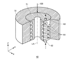
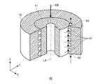
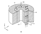
図3は、本実施形態に係るレンズ部40の第1の変形例を示す斜視図である。図4は、本実施形態に係るレンズ部40の第2の変形例を示す斜視図である。図5は、本実施形態に係るレンズ部40の第3の変形例を示す斜視図である。および、図6は、本実施形態に係るレンズ部40の第4の変形例を示す斜視図である。図3から図6において、図2に記載の部材と略同一の機能を有す部材には、同一の符号を付して、説明を省略する。図3から図6において、レンズ部40は、レンズ軸LAを中心軸とする貫通孔の周囲に形成される第1部材71と、第1部材71の外周を囲む第2部材とを有する。   FIG. 3 is a perspective view showing a first modification of the lens unit 40 according to the present embodiment. FIG. 4 is a perspective view showing a second modification of the lens unit 40 according to the present embodiment. FIG. 5 is a perspective view showing a third modification of the lens unit 40 according to the present embodiment. FIG. 6 is a perspective view showing a fourth modification of the lens unit 40 according to this embodiment. 3 to 6, members having substantially the same functions as those illustrated in FIG. 2 are denoted by the same reference numerals, and description thereof is omitted. 3 to 6, the lens unit 40 includes a first member 71 formed around a through hole having the lens axis LA as a central axis, and a second member surrounding the outer periphery of the first member 71.

図3から図6に示すレンズ部40の変形例は、第1部材71における第2部材72と接する外周部分および第2部材72における第1部材71と接する内周部分の少なくとも一方は、第1部材71の外周に沿って冷却用流体を流すための溝部61を有する。第1部材71の外周部分および第2部材72の内周部分は、貫通孔の延伸方向と平行な面の少なくとも一部であってよい。溝部61は、貫通孔の中心軸を通る面に対して対称に形成されてよい。   3 to 6, at least one of the outer peripheral portion of the first member 71 in contact with the second member 72 and the inner peripheral portion of the second member 72 in contact with the first member 71 is the first member 71. A groove 61 for flowing a cooling fluid is provided along the outer periphery of the member 71. The outer peripheral portion of the first member 71 and the inner peripheral portion of the second member 72 may be at least a part of a plane parallel to the extending direction of the through hole. The groove part 61 may be formed symmetrically with respect to a plane passing through the central axis of the through hole.

図3に示すレンズ部40の第1の変形例は、第1部材71における第2部材72と接する外周部分に、第1部材71の外周に沿って、冷却用流体を流すらせん状の溝部61を有する例を示す。図3に示す点線の矢印は、冷却用流体の流れる方向を表す。冷却用流体は、レンズ部40の電子ビームEBの出射側に設けられた流入部62から流入し、らせん状の溝部61に沿って、電子ビームEBの出射側から入射側に流れる。冷却用流体は、らせん状の溝部61を通過中にレンズ部40の熱を受け取り、温度が上昇する。冷却用流体は、電子ビームEBの入射側に設けられた排出部63から排出される。   A first modification of the lens unit 40 shown in FIG. 3 is a spiral groove 61 that allows a cooling fluid to flow along the outer periphery of the first member 71 in the outer peripheral portion of the first member 71 that contacts the second member 72. An example having The dotted arrow shown in FIG. 3 represents the direction in which the cooling fluid flows. The cooling fluid flows in from an inflow portion 62 provided on the exit side of the electron beam EB of the lens unit 40, and flows along the spiral groove 61 from the exit side of the electron beam EB to the incident side. The cooling fluid receives heat from the lens unit 40 while passing through the spiral groove 61, and the temperature rises. The cooling fluid is discharged from a discharge portion 63 provided on the incident side of the electron beam EB.

なお、冷却用流体は、レンズ部40の電子ビームEBの出射側に設けられた流入側流体槽64から流入部62へと流入し、排出部63からレンズ部40の電子ビームEBの入射側に設けられた排出側流体槽65へと排出されてよい。この場合、冷却用流体は、レンズ部40の外部に設けられた温度調整器160に達し、レンズ部40から受け取った熱を排熱する。ここで、流入側流体槽64、排出側流体槽65、および温度調整器160は、図2Aで示したので、図3においては記載を省略している。   The cooling fluid flows from an inflow side fluid tank 64 provided on the exit side of the electron beam EB of the lens unit 40 into the inflow unit 62, and from the discharge unit 63 to the incident side of the electron beam EB of the lens unit 40. It may be discharged to the provided discharge side fluid tank 65. In this case, the cooling fluid reaches the temperature regulator 160 provided outside the lens unit 40 and exhausts the heat received from the lens unit 40. Here, since the inflow side fluid tank 64, the discharge side fluid tank 65, and the temperature adjuster 160 are shown in FIG. 2A, the description is omitted in FIG.

図3において、第1部材71は、冷却用流体を流す一続きのらせん状の溝部61を一本有する例を示したが、これに代えて、第1部材71は、複数のらせん状の溝部61を有してもよい。この場合、レンズ部40は、複数のらせん状の溝部61に対応して、複数の流入部62および複数の排出部63を有してよい。   In FIG. 3, the first member 71 has an example having one continuous spiral groove 61 through which the cooling fluid flows. Instead, the first member 71 includes a plurality of spiral grooves. 61 may be included. In this case, the lens unit 40 may have a plurality of inflow portions 62 and a plurality of discharge portions 63 corresponding to the plurality of spiral grooves 61.

図4に示すレンズ部40の第2の変形例は、第2部材72における第1部材71と接する内周部分に、第2部材72の内周に沿って、冷却用流体を流すらせん状の溝部61を有する例を示す。図4に示す点線の矢印は、冷却用流体の流れる方向を表す。冷却用流体は、レンズ部40の電子ビームEBの出射側に設けられた流入部62から流入し、らせん状の溝部61に沿って、電子ビームEBの出射側から入射側に流れる。冷却用流体は、らせん状の溝部61を通過中にレンズ部40の熱を受け取り、温度が上昇する。冷却用流体は、電子ビームEBの入射側に設けられた排出部63から排出される。冷却用流体は、図3で説明した例と同様に、レンズ部40の外部に設置された温度調整器160に達し、レンズ部40から受け取った熱を排熱する。また、図4の例においても、第2部材72は、複数のらせん状の溝部61を有してよい。   In the second modification of the lens unit 40 shown in FIG. 4, a spiral fluid is allowed to flow along the inner periphery of the second member 72 to the inner peripheral portion of the second member 72 in contact with the first member 71. The example which has the groove part 61 is shown. The dotted arrow shown in FIG. 4 represents the direction in which the cooling fluid flows. The cooling fluid flows in from an inflow portion 62 provided on the exit side of the electron beam EB of the lens unit 40, and flows along the spiral groove 61 from the exit side of the electron beam EB to the incident side. The cooling fluid receives heat from the lens unit 40 while passing through the spiral groove 61, and the temperature rises. The cooling fluid is discharged from a discharge portion 63 provided on the incident side of the electron beam EB. As in the example described with reference to FIG. 3, the cooling fluid reaches the temperature regulator 160 installed outside the lens unit 40, and exhausts heat received from the lens unit 40. Also in the example of FIG. 4, the second member 72 may have a plurality of spiral grooves 61.

図3および図4に示すレンズ部40の例では、一本または複数本の一続きのらせん状の溝部61が、第1部材71の外周部分または第2部材72の内周部分を覆う。流入部62および排出部63は、一続きのらせん状の溝部61の両端に、それぞれ対応して設けられてよく、この場合、レンズ部40は、一または複数の流入部62および排出部63を有する。なお、例えば5個未満の少ない数の流入部62および排出部63がレンズ部40に設けられる場合、当該流入部62および排出部63は、流入側流体槽64および排出側流体槽65を経由せず、直接、温度調整器160と接続してもよい。   In the example of the lens portion 40 shown in FIGS. 3 and 4, one or a plurality of continuous spiral groove portions 61 cover the outer peripheral portion of the first member 71 or the inner peripheral portion of the second member 72. The inflow portion 62 and the discharge portion 63 may be provided at both ends of the continuous spiral groove portion 61, respectively. In this case, the lens portion 40 includes one or more inflow portions 62 and discharge portions 63. Have. For example, when a small number of inflow portions 62 and discharge portions 63 of less than five are provided in the lens unit 40, the inflow portion 62 and the discharge portion 63 are routed through the inflow side fluid tank 64 and the discharge side fluid tank 65. Instead, the temperature controller 160 may be directly connected.

図5に示すレンズ部40の第3の変形例は、第1部材71における第2部材72と接する外周部分に、第1部材71の外周に沿って、冷却用流体を流すための複数の直線状の溝部61を有する例を示す。図5に示す点線の矢印は、冷却用流体の流れる方向を表す。冷却用流体は、レンズ部40の電子ビームEBの出射側に設置した複数の流入部62から並列に、流入部62のそれぞれと対応する溝部61に流入し、複数の溝部61に沿って、電子ビームEBの出射側から入射側に流れる。冷却用流体は、直線状の溝部61を通過中にレンズ部40の熱を受け取り、温度が上昇する。冷却用流体は、電子ビームEBの入射側に設けられた複数の排出部63からそれぞれ排出される。冷却用流体は、図3で説明した例と同様に、レンズ部40の外部に設置された温度調整器160に達し、レンズ部40から受け取った熱を排熱する。   A third modification of the lens unit 40 shown in FIG. 5 is a plurality of straight lines for flowing a cooling fluid along the outer periphery of the first member 71 to the outer peripheral portion of the first member 71 in contact with the second member 72. An example having a groove portion 61 is shown. The dotted arrow shown in FIG. 5 represents the direction in which the cooling fluid flows. The cooling fluid flows in parallel from the plurality of inflow portions 62 installed on the emission side of the electron beam EB of the lens portion 40 into the groove portions 61 corresponding to each of the inflow portions 62, and along the plurality of groove portions 61, The beam EB flows from the exit side to the entrance side. The cooling fluid receives the heat of the lens unit 40 while passing through the linear groove 61, and the temperature rises. The cooling fluid is discharged from a plurality of discharge portions 63 provided on the incident side of the electron beam EB. As in the example described with reference to FIG. 3, the cooling fluid reaches the temperature regulator 160 installed outside the lens unit 40, and exhausts heat received from the lens unit 40.

図6に示すレンズ部40の第4の変形例は、第1部材71における第2部材72と接する外周部分に、第1部材71の外周に沿って、冷却用流体を流すための、複数の折り返された経路を持つ直線状の溝部61を有する例を示す。図6に示す点線の矢印は、冷却用流体の流れる方向を表す。冷却用流体は、レンズ部40の電子ビームEB出射側に設置した複数の流入部62から並列に、流入部62のそれぞれと対応する溝部61に流入し、複数の溝部61に沿って、電子ビームEB出射側から入射側に流れる。冷却用流体は、折り返された経路を持つ直線状の溝部61を通過中にレンズ部40の熱を受け取り、温度が上昇する。冷却用流体は、電子ビームEBの入射側に設けられた複数の排出部63からそれぞれ排出される。冷却用流体は、図3で説明した例と同様に、レンズ部40の外部に設置された温度調整器160に達し、レンズ部40から受け取った熱を排熱する。   A fourth modification of the lens unit 40 illustrated in FIG. 6 includes a plurality of cooling fluids that flow along the outer periphery of the first member 71 to the outer peripheral portion of the first member 71 that is in contact with the second member 72. The example which has the linear groove part 61 with the return | turnback path | route is shown. The dotted arrow shown in FIG. 6 represents the direction in which the cooling fluid flows. The cooling fluid flows in parallel from the plurality of inflow portions 62 provided on the electron beam EB emission side of the lens portion 40 into the groove portions 61 corresponding to each of the inflow portions 62, and travels along the plurality of groove portions 61 along the electron beam. It flows from the EB exit side to the entrance side. The cooling fluid receives the heat of the lens unit 40 while passing through the linear groove 61 having the folded path, and the temperature rises. The cooling fluid is discharged from a plurality of discharge portions 63 provided on the incident side of the electron beam EB. As in the example described with reference to FIG. 3, the cooling fluid reaches the temperature regulator 160 installed outside the lens unit 40, and exhausts heat received from the lens unit 40.

図5および図6に示す例では、レンズ部40は、複数の溝部61と、複数の溝部61のそれぞれに対応する複数の流入部62および複数の排出部63とを備える。複数の流入部62のそれぞれは、一つの流入側流体槽64と接続されてよい。複数の排出部63のそれぞれは、一つの排出側流体槽65と接続されてよい。流入側流体槽64は、温度調整器160から送りだされた冷却用流体を保持し、複数の流入部62に、冷却用流体を並列に供給する。また、排出側流体槽65は、複数の排出部63が並列に排出した冷却用流体を保持し、温度調整器160に戻す。   In the example shown in FIGS. 5 and 6, the lens unit 40 includes a plurality of groove portions 61, a plurality of inflow portions 62 and a plurality of discharge portions 63 corresponding to the plurality of groove portions 61, respectively. Each of the plurality of inflow portions 62 may be connected to one inflow side fluid tank 64. Each of the plurality of discharge parts 63 may be connected to one discharge side fluid tank 65. The inflow side fluid tank 64 holds the cooling fluid sent from the temperature regulator 160 and supplies the cooling fluid to the plurality of inflow portions 62 in parallel. The discharge side fluid tank 65 holds the cooling fluid discharged in parallel by the plurality of discharge portions 63 and returns it to the temperature regulator 160.

図3、図4、図5、および図6で示したレンズ部40の変形例において、第1部材71は、レンズ部40を貫通する貫通孔の周囲に形成された部材であり、第2部材72は、第1部材71の外周を囲む部材である。第1部材71および第2部材72は、レンズ部40を構成する障壁部41、励磁部42、および磁性体部43のうち、少なくとも1つを形成する。   In the modification of the lens unit 40 shown in FIGS. 3, 4, 5, and 6, the first member 71 is a member formed around a through hole that penetrates the lens unit 40, and the second member 72 is a member surrounding the outer periphery of the first member 71. The first member 71 and the second member 72 form at least one of the barrier part 41, the excitation part 42, and the magnetic part 43 that constitute the lens part 40.

例えば、第1部材71は、障壁部41の一部でよく、第2部材72は、磁性体部43の一部または全部である。また、第1部材71は、磁性体部43の一部または全部でよく、この場合、第2部材72は、励磁部42の一部または全部であってよい。また、第1部材71は、励磁部42の一部または全部でよく、この場合、第2部材72は、磁性体部43の一部または全部であってもよい。   For example, the first member 71 may be a part of the barrier part 41, and the second member 72 is a part or all of the magnetic part 43. Further, the first member 71 may be a part or all of the magnetic part 43, and in this case, the second member 72 may be a part or all of the excitation part 42. Further, the first member 71 may be a part or all of the excitation part 42, and in this case, the second member 72 may be a part or all of the magnetic body part 43.

これらに代えて、障壁部41、励磁部42、または磁性体部43のうち少なくとも1つが分割され、分割された一方および他方を、第1部材71および第2部材72としてもよい。この場合、分割された一方および他方のうち、レンズ軸LAに近い内側の円筒部分およびレンズ軸LAから遠い外側の円筒部分を、それぞれ、第1部材71および第2部材72に対応させてもよい。   Instead of these, at least one of the barrier portion 41, the excitation portion 42, and the magnetic body portion 43 may be divided, and one and the other divided may be used as the first member 71 and the second member 72. In this case, of the divided one and the other, the inner cylindrical portion close to the lens axis LA and the outer cylindrical portion far from the lens axis LA may correspond to the first member 71 and the second member 72, respectively. .

図3、図4、図5、および図6で示したレンズ部40の変形例において、溝部61は、第1部材71における第2部材72と接する外周部分および第2部材72における第1部材71と接する内周部分の少なくとも一方に形成され、他方の部分によって蓋状に覆われる。溝部61および、溝部61を覆う第1部材71の外周部分または第2部材72の内周部分の組み合わせは、冷却用流体を流す流路を形成する。   In the modification of the lens unit 40 shown in FIGS. 3, 4, 5, and 6, the groove 61 has an outer peripheral portion in contact with the second member 72 in the first member 71 and the first member 71 in the second member 72. Is formed on at least one of the inner peripheral portions in contact with the cover, and is covered like a lid by the other portion. The combination of the groove portion 61 and the outer peripheral portion of the first member 71 or the inner peripheral portion of the second member 72 covering the groove portion 61 forms a flow path through which the cooling fluid flows.

これにより、電子ビームレンズ装置30は、レンズ部40に対して新たな部材を追加することなく、冷却用流体を流す流路を形成することができ、当該レンズ部40の熱を排熱できる。このように、電子ビームレンズ装置30は、新たな部材を追加しないため、レンズ部40の内径d1および外径d2の大きさは、冷却用流体を流す流路がない場合の大きさと略同一の値にすることができる。即ち、例えば、レンズ部40の外径d2が略30mm以内で設計された電子ビームレンズに対して、外径d2の大きさを変えずに、冷却用流体を流す流路を更に設けたレンズ部40を提供することができる。   Accordingly, the electron beam lens device 30 can form a flow path for flowing a cooling fluid without adding a new member to the lens unit 40, and can exhaust heat of the lens unit 40. Thus, since the electron beam lens apparatus 30 does not add a new member, the size of the inner diameter d1 and the outer diameter d2 of the lens unit 40 is substantially the same as the size when there is no flow path for flowing the cooling fluid. Can be a value. That is, for example, for an electron beam lens designed with an outer diameter d2 of the lens portion 40 within about 30 mm, a lens portion further provided with a flow path for flowing a cooling fluid without changing the size of the outer diameter d2. 40 can be provided.

本実施形態に係る電子ビームレンズ装置30の排熱手段と、図11A,図11B、および図11Cに記載した電子ビームレンズの排熱手段とを比較する。本実施形態に係る排熱手段は、同じ流量の冷却用流体を流した場合に、図11Aに示す手段と比較して排熱能力が高い。図11Aに示す手段は、冷却用流体が、管81を介してレンズ構成部材と間接的に接触するのに対して、本実施形態に係る排熱手段は、冷却用流体が、電子ビームレンズ装置30の構成部材に形成された溝部61を流れることにより、電子ビームレンズ装置30の構成部材と直接接触するからである。   The heat exhausting means of the electron beam lens device 30 according to this embodiment is compared with the heat exhausting means of the electron beam lens described in FIGS. 11A, 11B, and 11C. The exhaust heat means according to the present embodiment has a higher exhaust heat capacity than the means shown in FIG. 11A when the same amount of cooling fluid is flowed. In the means shown in FIG. 11A, the cooling fluid is indirectly in contact with the lens component through the tube 81, whereas the exhaust heat means according to the present embodiment is such that the cooling fluid is an electron beam lens device. This is because it directly contacts the constituent members of the electron beam lens device 30 by flowing through the grooves 61 formed in the constituent members 30.

図11Aの管81を磁性体部43の外周に設けた場合と、略同一形状のレンズ部40に本実施形態の溝部61を磁性体部43の外周部分に設けた場合と、のそれぞれについて、排熱能力を調査した。レンズ部40の発熱を100Wにそれぞれ設定し、同じ流量の冷却用流体で排熱する場合の電子ビームレンズ装置30の所定位置の温度を比較した。図11Aの手段では、電子ビームレンズ装置30の所定位置の温度が70℃以上に上昇したのに対して、本実施形態の排熱手段では、同じ位置の温度は50℃以下に抑えることが可能であった。   Each of the case where the tube 81 of FIG. 11A is provided on the outer periphery of the magnetic body portion 43 and the case where the groove portion 61 of the present embodiment is provided on the outer peripheral portion of the magnetic body portion 43 in the lens portion 40 having substantially the same shape. The exhaust heat capacity was investigated. The heat generation of the lens unit 40 was set to 100 W, and the temperature at a predetermined position of the electron beam lens device 30 when the heat was exhausted with the cooling fluid having the same flow rate was compared. 11A, the temperature at a predetermined position of the electron beam lens device 30 has risen to 70 ° C. or higher, whereas the exhaust heat means of this embodiment can suppress the temperature at the same position to 50 ° C. or lower. Met.

本実施形態に係る電子ビームレンズ装置30の排熱手段と、図11Bに示す排熱手段とを比較する。図11Bの冷却用流体は、磁性体部43を貫通する直線状の貫通孔82を流れる。本実施形態の冷却用流体は、例えば、磁性体部43の外周部分に設けた溝部61に沿って流れる。溝部61の形状は、溝部61の長手方向(冷却用流体が流れる方向)、および断面方向(冷却用流体が流れる方向と直交する方向)ともに、さまざまな形状に形成できる。   The heat exhausting means of the electron beam lens device 30 according to this embodiment is compared with the heat exhausting means shown in FIG. 11B. The cooling fluid in FIG. 11B flows through a linear through hole 82 that penetrates the magnetic body portion 43. The cooling fluid of the present embodiment flows, for example, along the groove portion 61 provided in the outer peripheral portion of the magnetic body portion 43. The groove 61 can be formed in various shapes in both the longitudinal direction of the groove 61 (the direction in which the cooling fluid flows) and the cross-sectional direction (the direction perpendicular to the direction in which the cooling fluid flows).

図11Bの直線状の貫通孔82の場合と比較して、本実施形態の排熱手段は、冷却用流体が溝部61を循環する間に、冷却用流体とレンズ構成部材との間の接触面積を大きくすることができる。即ち、本実施形態に係る排熱手段は、図11Bの手段と比較して、高い排熱能力を実現できる。   Compared to the case of the linear through-hole 82 in FIG. 11B, the exhaust heat means of the present embodiment has a contact area between the cooling fluid and the lens constituent member while the cooling fluid circulates in the groove 61. Can be increased. That is, the heat exhausting means according to the present embodiment can realize a high heat exhausting capacity as compared with the means of FIG. 11B.

本実施形態に係る電子ビームレンズ装置30の排熱手段と、図11Cに示す排熱手段とを比較する。図11Cの励磁部42は、容器83内部の冷却用流体に浸っている。一方、本実施形態の励磁部42は、冷却用流体とは完全に分離できる。本実施形態の冷却用流体は、励磁部42とは直接に接触しないで、レンズ内を循環する。本実施形態に係る排熱手段は、冷却用流体を循環させながら、励磁部42に安定に電流を流すことが可能である。即ち、本実施形態に係る電子ビームレンズ装置30は、外径等の大きさの変更なしに、冷却用流体を流す流路を形成し、排熱能力を向上させることができる。   The heat exhausting means of the electron beam lens apparatus 30 according to this embodiment is compared with the heat exhausting means shown in FIG. 11C. The excitation unit 42 in FIG. 11C is immersed in the cooling fluid inside the container 83. On the other hand, the excitation part 42 of this embodiment can be completely separated from the cooling fluid. The cooling fluid of the present embodiment circulates in the lens without directly contacting the excitation unit 42. The exhaust heat unit according to the present embodiment can flow a current stably to the excitation unit 42 while circulating the cooling fluid. That is, the electron beam lens device 30 according to the present embodiment can improve the heat exhaust capability by forming a flow path for flowing the cooling fluid without changing the size of the outer diameter or the like.

本実施形態に係る溝部61の製造方法について説明する。溝部61は、電子ビームレンズ装置30を組立てる前に、レンズ構成部材の内周部分または外周部分の表面を、あらかじめ加工することによって設けられてよい。溝部61は、一例として、当該部材の表面を切削することによって設けられる。この場合、溝部61は、当該溝部61の長手方向(冷却用流体が流れる方向)、および断面方向(冷却用流体が流れる方向と直交する方向)の形状が、所定の形状になるように、切削工具を当該部材に対して相対的に移動して切削することで設けられてよい。   The manufacturing method of the groove part 61 which concerns on this embodiment is demonstrated. The groove 61 may be provided by processing the surface of the inner peripheral portion or the outer peripheral portion of the lens component member in advance before assembling the electron beam lens device 30. As an example, the groove 61 is provided by cutting the surface of the member. In this case, the groove 61 is cut so that the longitudinal direction of the groove 61 (the direction in which the cooling fluid flows) and the cross-sectional direction (the direction perpendicular to the direction in which the cooling fluid flows) have a predetermined shape. You may provide by moving a tool relatively with respect to the said member and cutting.

これに代えて、溝部61は、電子ビームレンズ装置30の構成部材と共に設けられてもよい。例えば、3Dプリンター等により、材料を積層して当該構成部材を製作する場合、溝部61となるべき部分には材料を積層せずに製作することで、所定の溝部61を有する構成部材を形成することができる。   Instead of this, the groove 61 may be provided together with the constituent members of the electron beam lens device 30. For example, when manufacturing the constituent member by laminating materials by a 3D printer or the like, the constituent member having the predetermined groove portion 61 is formed by manufacturing without stacking the material on the portion to be the groove portion 61. be able to.

本実施形態に係る冷却用流体の循環について次に説明する。冷却用流体は、微量の防錆成分を混入した冷却水であってよい。ここでは、水を主成分とする冷却水を冷却用流体として、図2に示すらせん状の溝部61に流す場合について説明する。   Next, circulation of the cooling fluid according to the present embodiment will be described. The cooling fluid may be cooling water mixed with a small amount of a rust preventive component. Here, the case where the cooling water which has water as a main component is made to flow in the spiral groove part 61 shown in FIG. 2 as a cooling fluid is demonstrated.

冷却水の流量をUとし、溝部61が形成される冷却水流路の管径をDとした場合に、冷却水の流れが層流となる条件を検討する。ここで、冷却水の流れが層流となる条件は、冷却水の流れによって、電子ビームレンズが振動することを防止する条件と考えられる。なお、冷却水流路の管径Dは、流路と同じ断面積を有する円管を考慮した場合の、当該円管の直径とした。   A condition in which the flow of the cooling water becomes a laminar flow when the flow rate of the cooling water is U and the pipe diameter of the cooling water flow path in which the groove 61 is formed is D will be examined. Here, the condition that the flow of the cooling water becomes a laminar flow is considered to be a condition for preventing the electron beam lens from vibrating due to the flow of the cooling water. Note that the pipe diameter D of the cooling water flow path is the diameter of the circular pipe when a circular pipe having the same cross-sectional area as the flow path is taken into consideration.

冷却水の流速Vは、冷却水の流量Uと管径Dとから、以下の(数1)により計算される。ここで、冷却水の密度ρは1g/cm、粘度μは1mPa・s(ミリパスカル・秒)である。この場合、溝部61の冷却水流路を流れる冷却水のレイノルズ数Reは、以下の(数2)により計算される。
(数1)
V=4×U/(πD
(数2)
Re=V×D/(μ/ρ)
The cooling water flow velocity V is calculated by the following (Equation 1) from the cooling water flow rate U and the pipe diameter D. Here, the density ρ of the cooling water is 1 g / cm 3 , and the viscosity μ is 1 mPa · s (millipascal · second). In this case, the Reynolds number Re of the cooling water flowing through the cooling water flow path of the groove 61 is calculated by the following (Equation 2).
(Equation 1)
V = 4 × U / (πD 2 )
(Equation 2)
Re = V × D / (μ / ρ)

レイノルズ数Reが、例えば2000以下の値の場合に、冷却水の流れは層流となる。レンズ構成部材の大きさの条件、およびレイノルズ数Reが2000以下の条件から、冷却水の流量Uと溝部61の断面積または管径Dとの関係を見積もる。   When the Reynolds number Re is a value of 2000 or less, for example, the flow of the cooling water is a laminar flow. The relationship between the cooling water flow rate U and the cross-sectional area of the groove 61 or the tube diameter D is estimated from the condition of the size of the lens component and the condition that the Reynolds number Re is 2000 or less.

レンズ部40の外周部分に溝部61を形成する場合において、流量Uが1mL/s〜2mL/s(ミリリットル毎秒)の冷却水を層流で流すためには、溝部61の断面積は0.5mm以上1mm以下であり、流入部62側と排出部63側との間に少なくとも2本の並列な溝部61が設けられることが望ましい。レンズ部40の外径を22mm以上30mm以下とした場合、溝部61を形成するレンズ部40の外周部分の大きさから、形成できる溝部61の長さLは0.7m以上1.5m以下である。 In the case where the groove portion 61 is formed in the outer peripheral portion of the lens portion 40, in order to flow the cooling water having a flow rate U of 1 mL / s to 2 mL / s (milliliter per second) in a laminar flow, the cross-sectional area of the groove portion 61 is 0.5 mm. 2 or more 1 mm 2 or less, it is desirable that at least two parallel grooves 61 is provided between the inlet portion 62 side and the discharge section 63 side. When the outer diameter of the lens part 40 is 22 mm or more and 30 mm or less, the length L of the groove part 61 that can be formed is 0.7 m or more and 1.5 m or less because of the size of the outer peripheral part of the lens part 40 that forms the groove part 61. .

図7は、このような溝部61からなる冷却水流路において、冷却水の流量Uと、溝部61の両端の圧力差Pおよび排水温度Toとの関係をシミュレーションした結果の一例を示す。図7の横軸は、2本の並列な溝部61に流れる冷却水の総流量Uを示す。冷却水の総流量Uは1mL/s〜2mL/sの範囲の値である。   FIG. 7 shows an example of a result of simulating the relationship between the flow rate U of the cooling water, the pressure difference P at both ends of the groove 61 and the drainage temperature To in the cooling water flow path including the groove 61. The horizontal axis of FIG. 7 shows the total flow rate U of the cooling water flowing through the two parallel groove portions 61. The total flow rate U of the cooling water is a value in the range of 1 mL / s to 2 mL / s.

グラフ(a)は、流入部62側と排出部63側との間に現れる冷却水の圧力差Pを表す。図7の左側の縦軸は、グラフ(a)と対応する圧力差の大きさを示す。グラフ(b)は、排出部63から排水される冷却水の温度Toを表す。温度調整器160を経由して20℃に温度調整された冷却水が溝部61に流入するものとした。図7の右側の縦軸が、グラフ(b)と対応する排水温度を示す。   The graph (a) represents the pressure difference P of the cooling water that appears between the inflow portion 62 side and the discharge portion 63 side. The vertical axis on the left side of FIG. 7 indicates the magnitude of the pressure difference corresponding to the graph (a). The graph (b) represents the temperature To of the cooling water discharged from the discharge part 63. The cooling water whose temperature was adjusted to 20 ° C. via the temperature regulator 160 was assumed to flow into the groove 61. The vertical axis on the right side of FIG. 7 indicates the drainage temperature corresponding to the graph (b).

圧力差Pは、冷却水の流れに対する摩擦係数λから、次に示す(数3)の関係式で計算される。ここで、冷却水の流れに対する摩擦係数λは、レイノルズ数Reから(数4)の関係式で計算される。また、冷却水の排水温度Toは、温度20℃で流入部62から流入し、電子ビームレンズの100Wの発熱をすべて排熱するものとして計算される。
(数3)
P=λ×(L/d)×(1/2)×(ρ×V
(数4)
λ=64/Re
The pressure difference P is calculated by the following relational expression (Formula 3) from the friction coefficient λ with respect to the flow of the cooling water. Here, the friction coefficient λ with respect to the flow of the cooling water is calculated from the Reynolds number Re by the relational expression (Expression 4). Further, the drainage temperature To of the cooling water is calculated as that which flows from the inflow portion 62 at a temperature of 20 ° C. and exhausts all 100 W of the electron beam lens.
(Equation 3)
P = λ × (L / d) × (1/2) × (ρ × V 2 )
(Equation 4)
λ = 64 / Re

図7は、一例として、溝部61からなる冷却水流路の両端の15×10Pa程度の圧力差Pに抗して、流量1.5mL/sの冷却水を溝部61に流せば、電子ビームレンズの100Wの発熱を、排水温度Toが40℃以下となる条件で排熱できることを示す。図7は、図に示す範囲の冷却水流量Uと圧力差Pとを設定することにより、電子ビームレンズの発熱が100W以上の場合であっても排熱可能であることを示している。 FIG. 7 shows, as an example, an electron beam that flows through the groove 61 with a flow rate of 1.5 mL / s against the pressure difference P of about 15 × 10 3 Pa at both ends of the cooling water flow path including the groove 61. It shows that the heat generation of 100 W of the lens can be exhausted under the condition that the drainage temperature To is 40 ° C. or less. FIG. 7 shows that by setting the cooling water flow rate U and the pressure difference P in the range shown in the drawing, the heat can be exhausted even when the heat generated by the electron beam lens is 100 W or more.

さらに、図7の条件が得られる溝部61の断面積は、0.5mm以上1mm以下であり、溝部61の深さは1mm以下である。即ち、溝部61を形成するレンズ部40の外周部分、即ち図2では磁性体部43の外周部分、の動径方向幅が、例えば3mm以下であっても、排熱可能であることを示している。本実施形態に係るレンズ部40の外周部分は、このような溝部61を形成できるので、電子ビームレンズ装置30は、100W以上の発熱に対応できることがわかる。 Furthermore, the cross-sectional area of the groove part 61 from which the conditions of FIG. 7 are obtained is 0.5 mm 2 or more and 1 mm 2 or less, and the depth of the groove part 61 is 1 mm or less. That is, even if the outer peripheral portion of the lens portion 40 forming the groove portion 61, that is, the outer peripheral portion of the magnetic body portion 43 in FIG. Yes. Since the outer peripheral portion of the lens unit 40 according to the present embodiment can form such a groove 61, it can be seen that the electron beam lens device 30 can cope with heat generation of 100 W or more.

図8は、本実施形態に係る電子ビーム露光装置100の変形例を示す。本変形例の電子ビーム露光装置100において、図1に示された電子ビーム露光装置100と略同一の動作をする部分には、同一の符号を付け、説明を省略する。図8に示す電子ビーム露光装置100の変形例は、試料10を載置してXY平面方向に移動させる1つのステージ部110と、XY平面内に並ぶ複数の円柱形のカラム部120と、ステージ部110および複数のカラム部120を制御する露光制御部140とを備える。   FIG. 8 shows a modification of the electron beam exposure apparatus 100 according to this embodiment. In the electron beam exposure apparatus 100 of the present modification, the same reference numerals are given to portions that perform substantially the same operations as those of the electron beam exposure apparatus 100 shown in FIG. A modification of the electron beam exposure apparatus 100 shown in FIG. 8 includes a stage unit 110 on which the sample 10 is placed and moved in the XY plane direction, a plurality of columnar column units 120 arranged in the XY plane, and a stage. And an exposure control unit 140 that controls the unit 110 and the plurality of column units 120.

複数のカラム部120のそれぞれは、露光制御部140に接続され、それぞれのカラム部120が、ステージ部110によって可動とされる試料10の範囲を露光する。複数本のカラム部120は、並列して露光を進めることができるため、露光のスループットを大幅に向上できる。また、試料10が300mm以上の大口径の半導体ウエハ等であっても、当該半導体ウエハに対応してカラム部120の数を増加させることで、スループットが著しく低下することを防止できる。   Each of the plurality of column units 120 is connected to the exposure control unit 140, and each column unit 120 exposes a range of the sample 10 that is movable by the stage unit 110. Since the plurality of column sections 120 can advance the exposure in parallel, the throughput of exposure can be greatly improved. Further, even if the sample 10 is a semiconductor wafer having a large diameter of 300 mm or more, the throughput can be prevented from being significantly reduced by increasing the number of column portions 120 corresponding to the semiconductor wafer.

図8に示す電子ビーム露光装置100の変形例は、X方向およびY方向において、予め定められた間隔でカラム部120が設けられる例を示す。例えば、複数のカラム部120は、X方向およびY方向ともに、ピッチ30mmで配置される。この場合、直径300mmの試料10上に、88本のカラム部120を配列することができる。また、この場合、カラム部120を構成するそれぞれのレンズ部40の外径d2は、30mm以下となる。また、例えば、複数のカラム部120は、X方向およびY方向ともに、ピッチ22mmで配置される。この場合、カラム部120を構成するそれぞれのレンズ部40の外径d2は22mm以下となる。これにより、直径300mmの試料10のウエハ上に157本のカラム部120を並べることができる。   The modification of the electron beam exposure apparatus 100 shown in FIG. 8 shows an example in which the column portions 120 are provided at predetermined intervals in the X direction and the Y direction. For example, the plurality of column parts 120 are arranged at a pitch of 30 mm in both the X direction and the Y direction. In this case, 88 column parts 120 can be arranged on the sample 10 having a diameter of 300 mm. In this case, the outer diameter d2 of each lens unit 40 constituting the column unit 120 is 30 mm or less. Further, for example, the plurality of column parts 120 are arranged at a pitch of 22 mm in both the X direction and the Y direction. In this case, the outer diameter d2 of each lens part 40 which comprises the column part 120 will be 22 mm or less. Thereby, 157 column parts 120 can be arranged on the wafer of the sample 10 having a diameter of 300 mm.

図9は、図8の電子ビーム露光装置100の変形例と対応する電子ビームレンズの構成を示す断面図である。図9は、図8に示す複数本のカラム部120をXY平面に平行な平面PQRSで切断した断面図の一部を示す。図9は、以上の本実施形態に係る電子ビームレンズ装置30の構成部材と略同一の機能を有する部材には、同一の符号を付して、説明を省略する。図9は、複数のカラム部120が、X方向およびY方向ともにピッチ30mmで配置された例を示す。また、図9は、レンズ部40の外径d2がそれぞれ30mmである例を示す。   FIG. 9 is a cross-sectional view showing a configuration of an electron beam lens corresponding to a modification of the electron beam exposure apparatus 100 of FIG. FIG. 9 shows a part of a cross-sectional view of the plurality of column parts 120 shown in FIG. 8 cut by a plane PQRS parallel to the XY plane. In FIG. 9, members having substantially the same functions as those of the constituent members of the electron beam lens device 30 according to the present embodiment described above are denoted by the same reference numerals, and description thereof is omitted. FIG. 9 shows an example in which a plurality of column parts 120 are arranged at a pitch of 30 mm in both the X direction and the Y direction. FIG. 9 shows an example in which the outer diameter d2 of the lens portion 40 is 30 mm.

それぞれのカラム部120の中心を通り、XY断面と垂直な複数の直線は、複数のカラム部120を構成するレンズ部40にそれぞれ対応するレンズ軸LAに相当する。複数のレンズ部40は、レンズ軸LAを中心に断面が同心円状の、障壁部41、励磁部42、および磁性体部43をそれぞれ有する。   A plurality of straight lines that pass through the center of each column portion 120 and are perpendicular to the XY cross section correspond to lens axes LA corresponding to the lens portions 40 constituting the plurality of column portions 120, respectively. The plurality of lens portions 40 each have a barrier portion 41, an excitation portion 42, and a magnetic body portion 43 having a concentric cross section around the lens axis LA.

また、一のカラム部120が有するレンズ部40と、一のカラム部120に隣接するカラム部120が有するレンズ部40との間には、支持部50が設けられる。即ち、複数のカラム部120がそれぞれ有するレンズ部40は、外周部分の一部において、支持部50の対応する部分と接する。カラム部120が配列されるピッチが略同一のまま、レンズ部40の外径が小さくなると、隣接するカラム部120の間の隙間は増加し、支持部50は、増加した隙間の領域に対応して設けられてよい。これにより、支持部50のそれぞれは、隣接するカラム部120間のXY面内方向の間隔を規定する。   In addition, a support unit 50 is provided between the lens unit 40 included in one column unit 120 and the lens unit 40 included in the column unit 120 adjacent to the one column unit 120. That is, each of the lens units 40 included in the plurality of column units 120 is in contact with a corresponding part of the support unit 50 in a part of the outer peripheral part. When the outer diameter of the lens unit 40 is reduced while the pitch at which the column units 120 are arranged is substantially the same, the gap between the adjacent column units 120 increases, and the support unit 50 corresponds to the increased gap region. May be provided. Thereby, each of the support portions 50 defines an interval in the XY in-plane direction between the adjacent column portions 120.

このように、支持部50およびレンズ部40は、接して設けられるので、レンズ部40における支持部50と接する外周部分、および支持部50におけるレンズ部40と接する部分の少なくとも一方に、レンズ部40の外周に沿って冷却用流体を流す溝部61を設けてよい。このようなレンズ部40について図10を用いて説明する。図10は、本実施形態に係るレンズ部40の第5の変形例を示す斜視図である。図10は、レンズ部40が、支持部50と接する外周部分に、冷却用流体を流す溝部61を有する例を示す。   Thus, since the support part 50 and the lens part 40 are provided in contact with each other, at least one of the outer peripheral part in contact with the support part 50 in the lens part 40 and the part in contact with the lens part 40 in the support part 50 is provided. You may provide the groove part 61 which flows the fluid for cooling along the outer periphery of this. Such a lens unit 40 will be described with reference to FIG. FIG. 10 is a perspective view showing a fifth modification of the lens unit 40 according to the present embodiment. FIG. 10 shows an example in which the lens portion 40 has a groove portion 61 through which a cooling fluid flows in an outer peripheral portion in contact with the support portion 50.

図10は、図示されていない支持部50の側から、レンズ部40の外周を構成する磁性体部43と溝部61を示した斜視図である。なお、図10は、支持部50を省略し、レンズ部40の直径を30mm未満として、溝部61の配置を確認できるようにした図である。図10は、支持部50と接する磁性体部43の外周部分に、4本の溝部61が、それぞれの磁性体部43を取り囲んで対称に配置された例を示す。レンズ部40のそれぞれに設けられた4本の溝部61を流れる冷却用流体は、レンズ部40がそれぞれ発生する熱を排熱する。   FIG. 10 is a perspective view showing the magnetic body portion 43 and the groove portion 61 constituting the outer periphery of the lens portion 40 from the support portion 50 side not shown. FIG. 10 is a diagram in which the support portion 50 is omitted and the diameter of the lens portion 40 is less than 30 mm so that the arrangement of the groove portions 61 can be confirmed. FIG. 10 shows an example in which four groove portions 61 are arranged symmetrically around each magnetic body portion 43 on the outer peripheral portion of the magnetic body portion 43 in contact with the support portion 50. The cooling fluid flowing through the four groove portions 61 provided in each of the lens portions 40 exhausts heat generated by the lens portions 40.

一例として、88本のカラム部120を有する電子ビーム露光装置100のカラム部全体が発生する8.8KW(=100W×88)以上の熱は、複数の(88の)レンズ部40にそれぞれ設けられた、複数の溝部61を循環する冷却用流体によって排熱される。例えば、溝部61のすべてを循環する冷却用流体の総流量は、略530mL/s(=1.5mL/s×4×88)である。これは、略32L/m(リットル毎分)の流量に相当する。温度調整器160は、流入側と排出側との略15×10Paの圧力差に抗して、略40℃に上昇した排水温度Toを20℃に温度調整しながら、全体として略32L/mの冷却水を循環させる。 As an example, heat of 8.8 KW (= 100 W × 88) or more generated by the entire column unit of the electron beam exposure apparatus 100 having 88 column units 120 is provided to each of the plurality of (88) lens units 40. Further, the heat is exhausted by the cooling fluid circulating through the plurality of grooves 61. For example, the total flow rate of the cooling fluid that circulates all of the grooves 61 is approximately 530 mL / s (= 1.5 mL / s × 4 × 88). This corresponds to a flow rate of approximately 32 L / m (liter per minute). The temperature controller 160 adjusts the temperature of the drainage water To, which has risen to about 40 ° C. to 20 ° C., against the pressure difference of about 15 × 10 3 Pa between the inflow side and the discharge side, and is about 32 L / w as a whole. circulate m cooling water.

これにより、複数のカラム部120を備える電子ビーム露光装置100においても、複数のカラム部120の外径等の大きさの変更なしに、冷却用流体を流す流路を形成し、排熱能力を向上させることができる。なお、図10において、複数のレンズ部40が、支持部50と接する磁性体部43の外周部分に、溝部61を形成する例を説明した。これに代えて、複数のレンズ部40は、図3、図4、図5、および図6で示したように、レンズ部40を構成する第1部材71および第2部材72の少なくとも一方に形成されてよい。   As a result, even in the electron beam exposure apparatus 100 including the plurality of column portions 120, a flow path for flowing the cooling fluid is formed without changing the size of the plurality of column portions 120 such as the outer diameter, and the heat exhaust capability is increased. Can be improved. In FIG. 10, the example in which the plurality of lens portions 40 form the groove portion 61 in the outer peripheral portion of the magnetic body portion 43 in contact with the support portion 50 has been described. Instead, the plurality of lens portions 40 are formed on at least one of the first member 71 and the second member 72 constituting the lens portion 40 as shown in FIGS. 3, 4, 5, and 6. May be.

以上、本発明を実施の形態を用いて説明したが、本発明の技術的範囲は上記実施の形態に記載の範囲には限定されない。上記実施の形態に、多様な変更または改良を加えることが可能であることが当業者に明らかである。その様な変更または改良を加えた形態も本発明の技術的範囲に含まれ得ることが、特許請求の範囲の記載から明らかである。   As mentioned above, although this invention was demonstrated using embodiment, the technical scope of this invention is not limited to the range as described in the said embodiment. It will be apparent to those skilled in the art that various modifications or improvements can be added to the above-described embodiment. It is apparent from the scope of the claims that the embodiments added with such changes or improvements can be included in the technical scope of the present invention.

特許請求の範囲、明細書、および図面中において示した装置、システム、プログラム、および方法における動作、手順、ステップ、および段階等の各処理の実行順序は、特段「より前に」、「先立って」等と明示しておらず、また、前の処理の出力を後の処理で用いるのでない限り、任意の順序で実現しうることに留意すべきである。特許請求の範囲、明細書、および図面中の動作フローに関して、便宜上「まず、」、「次に、」等を用いて説明したとしても、この順で実施することが必須であることを意味するものではない。   The order of execution of each process such as operations, procedures, steps, and stages in the apparatus, system, program, and method shown in the claims, the description, and the drawings is particularly “before” or “prior to”. It should be noted that the output can be realized in any order unless the output of the previous process is used in the subsequent process. Regarding the operation flow in the claims, the description, and the drawings, even if it is described using “first”, “next”, etc. for convenience, it means that it is essential to carry out in this order. It is not a thing.

10 試料、20 電子源、22 真空容器、30 電子ビームレンズ装置、40 レンズ部、41 障壁部、42 励磁部、43 磁性体部、44 ギャップ部、50 支持部、61 溝部、62 流入部、63 排出部、64 流入側流体槽、65 排出側流体槽、71 第1部材、72 第2部材、81 管、82 貫通孔、83 容器、100 電子ビーム露光装置、110 ステージ部、112 真空容器、120 カラム部、140 露光制御部、160 温度調整器 DESCRIPTION OF SYMBOLS 10 Sample, 20 Electron source, 22 Vacuum container, 30 Electron beam lens apparatus, 40 Lens part, 41 Barrier part, 42 Excitation part, 43 Magnetic body part, 44 Gap part, 50 Support part, 61 Groove part, 62 Inflow part, 63 Discharge section, 64 Inflow side fluid tank, 65 Discharge side fluid tank, 71 First member, 72 Second member, 81 Tube, 82 Through hole, 83 Container, 100 Electron beam exposure apparatus, 110 Stage section, 112 Vacuum container, 120 Column part, 140 Exposure control part, 160 Temperature controller

Claims (14)

荷電粒子ビームを通過させる貫通孔の周囲に形成され、前記荷電粒子ビームを収束または拡散させるレンズ部と、
前記レンズ部の外周を囲む支持部と、
を備え、
前記レンズ部における前記支持部と接する外周部分および前記支持部における前記レンズ部と接する内周部分の少なくとも一方は、前記レンズ部の外周に沿って冷却用流体を流すための溝部を有する
荷電粒子ビームレンズ装置。
A lens unit that is formed around a through-hole through which the charged particle beam passes, and converges or diffuses the charged particle beam;
A support part surrounding the outer periphery of the lens part;
With
At least one of an outer peripheral portion in contact with the support portion in the lens portion and an inner peripheral portion in contact with the lens portion in the support portion has a groove portion for flowing a cooling fluid along the outer periphery of the lens portion. Lens device.
荷電粒子ビームを通過させる貫通孔の周囲に形成され、前記荷電粒子ビームを収束または拡散させるレンズ部と、
前記レンズ部の外周を囲む支持部と、
を備え、
前記レンズ部は、
前記貫通孔の周囲に形成される第1部材と、
前記第1部材の外周を囲む第2部材と、
を有し、
前記第1部材における前記第2部材と接する外周部分および前記第2部材における前記第1部材と接する内周部分の少なくとも一方は、前記第1部材の外周に沿って冷却用流体を流すための溝部を有する
荷電粒子ビームレンズ装置。
A lens unit that is formed around a through-hole through which the charged particle beam passes, and converges or diffuses the charged particle beam;
A support part surrounding the outer periphery of the lens part;
With
The lens part is
A first member formed around the through hole;
A second member surrounding the outer periphery of the first member;
Have
At least one of an outer peripheral portion in contact with the second member in the first member and an inner peripheral portion in contact with the first member in the second member is a groove portion for flowing a cooling fluid along the outer periphery of the first member. A charged particle beam lens apparatus.
前記外周部分および前記内周部分は、前記貫通孔の延伸方向と平行な面の少なくとも一部である請求項1または2に記載の荷電粒子ビームレンズ装置。   The charged particle beam lens device according to claim 1, wherein the outer peripheral portion and the inner peripheral portion are at least a part of a plane parallel to the extending direction of the through hole. 前記溝部は、前記貫通孔の中心軸を通る面に対して対称に形成される請求項1から3のいずれか一項に記載の荷電粒子ビームレンズ装置。   4. The charged particle beam lens device according to claim 1, wherein the groove is formed symmetrically with respect to a plane passing through a central axis of the through hole. 5. 前記溝部の一端と接続する流入部と、
前記溝部の他端と接続する排出部と、
を備え、
前記溝部は、前記流入部から流入する冷却用流体を前記排出部から排出する請求項1から4のいずれか一項に記載の荷電粒子ビームレンズ装置。
An inflow portion connected to one end of the groove portion;
A discharge portion connected to the other end of the groove portion;
With
5. The charged particle beam lens device according to claim 1, wherein the groove portion discharges the cooling fluid flowing in from the inflow portion from the discharge portion. 6.
前記流入部は、前記レンズ部の、前記荷電粒子ビームが出射する側に形成され、
前記排出部は、前記レンズ部の、前記荷電粒子ビームが入射する側に形成される請求項5に記載の荷電粒子ビームレンズ装置。
The inflow portion is formed on a side of the lens portion where the charged particle beam is emitted,
The charged particle beam lens apparatus according to claim 5, wherein the discharge unit is formed on a side of the lens unit on which the charged particle beam is incident.
前記流入部に接続され、前記流入部から冷却用流体を供給する流入側流体槽と、
前記排出部に接続され、前記排出部から前記溝部を通過した冷却用流体を排出する排出側流体槽と、を備える請求項5または6に記載の荷電粒子ビームレンズ装置。
An inflow side fluid tank connected to the inflow portion and supplying a cooling fluid from the inflow portion;
The charged particle beam lens apparatus according to claim 5, further comprising: a discharge-side fluid tank that is connected to the discharge unit and discharges the cooling fluid that has passed through the groove from the discharge unit.
複数の前記溝部と、複数の前記溝部のそれぞれに対応する複数の前記流入部および複数の前記排出部を備える請求項5から7のいずれか一項に記載の荷電粒子ビームレンズ装置。   The charged particle beam lens device according to any one of claims 5 to 7, comprising a plurality of the groove portions, a plurality of the inflow portions and a plurality of the discharge portions corresponding to the plurality of groove portions, respectively. 前記レンズ部は、前記貫通孔の延伸方向と平行な中心軸を有する円柱形状に形成され、外径が22mm以上30mm以内である請求項1から8のいずれか一項に記載の荷電粒子ビームレンズ装置。   The charged particle beam lens according to any one of claims 1 to 8, wherein the lens portion is formed in a cylindrical shape having a central axis parallel to the extending direction of the through-hole and has an outer diameter of 22 mm or more and 30 mm or less. apparatus. 前記溝部は、水を主成分とする冷却水を前記冷却用流体として流す請求項1から9のいずれか一項に記載の荷電粒子ビームレンズ装置。   The charged particle beam lens device according to any one of claims 1 to 9, wherein the groove portion causes cooling water containing water as a main component to flow as the cooling fluid. 前記溝部は、断面積が0.5mm以上1mm以下であり、長さが0.7m以上1.5m以下である、請求項10に記載の荷電粒子ビームレンズ装置。 The charged particle beam lens device according to claim 10, wherein the groove has a cross-sectional area of 0.5 mm 2 to 1 mm 2 and a length of 0.7 m to 1.5 m. 前記レンズ部は、
前記貫通孔を形成する障壁部と、
前記貫通孔の延伸方向の磁場を発生させる励磁部と、
前記励磁部が発生させた磁場の方向を調節する磁性体部と、
を有し、
前記第1部材および前記第2部材は、前記障壁部、前記励磁部、および前記磁性体部のうち、少なくとも1つを形成する請求項2に記載の荷電粒子ビームレンズ装置。
The lens part is
A barrier portion that forms the through hole;
An excitation unit for generating a magnetic field in the extending direction of the through hole;
A magnetic part for adjusting the direction of the magnetic field generated by the excitation part;
Have
The charged particle beam lens device according to claim 2, wherein the first member and the second member form at least one of the barrier portion, the excitation portion, and the magnetic body portion.
荷電粒子ビームを放出する粒子源と、
請求項1から12のいずれか一項に記載の荷電粒子ビームレンズ装置と、
を有する荷電粒子ビームカラム。
A particle source that emits a charged particle beam;
The charged particle beam lens device according to any one of claims 1 to 12,
A charged particle beam column.
請求項13に記載の荷電粒子ビームカラムを1または複数備える荷電粒子ビーム露光装置。   A charged particle beam exposure apparatus comprising one or a plurality of charged particle beam columns according to claim 13.
JP2016012798A 2016-01-26 2016-01-26 Charged particle beam lens device, charged particle beam column, and charged particle beam exposure device Withdrawn JP2017135218A (en)

Priority Applications (7)

Application Number Priority Date Filing Date Title
JP2016012798A JP2017135218A (en) 2016-01-26 2016-01-26 Charged particle beam lens device, charged particle beam column, and charged particle beam exposure device
EP16195044.9A EP3200216A1 (en) 2016-01-26 2016-10-21 Charged particle beam lens apparatus, charged particle beam column, and charged particle beam exposure apparatus
TW107123125A TW201907435A (en) 2016-01-26 2016-10-24 Charged particle beam lens apparatus, charged particle beam column, and charged particle beam exposure apparatus
TW105134224A TWI632586B (en) 2016-01-26 2016-10-24 Charged particle beam lens device, charged particle beam cylinder, and charged particle beam exposure device
KR1020160141442A KR101877633B1 (en) 2016-01-26 2016-10-27 Charged particle beam lens apparatus, charged particle beam column and charged particle beam exposure apparatus
US15/335,448 US10049854B2 (en) 2016-01-26 2016-10-27 Charged particle beam lens apparatus, charged particle beam column, and charged particle beam exposure apparatus
CN201610958663.3A CN107017142A (en) 2016-01-26 2016-10-28 Charged particle beam lens devices, charged particle beam post and charged particle beam exposure apparatus

Applications Claiming Priority (1)

Application Number Priority Date Filing Date Title
JP2016012798A JP2017135218A (en) 2016-01-26 2016-01-26 Charged particle beam lens device, charged particle beam column, and charged particle beam exposure device

Publications (1)

Publication Number Publication Date
JP2017135218A true JP2017135218A (en) 2017-08-03

Family

ID=57206039

Family Applications (1)

Application Number Title Priority Date Filing Date
JP2016012798A Withdrawn JP2017135218A (en) 2016-01-26 2016-01-26 Charged particle beam lens device, charged particle beam column, and charged particle beam exposure device

Country Status (6)

Country Link
US (1) US10049854B2 (en)
EP (1) EP3200216A1 (en)
JP (1) JP2017135218A (en)
KR (1) KR101877633B1 (en)
CN (1) CN107017142A (en)
TW (2) TW201907435A (en)

Families Citing this family (4)

* Cited by examiner, † Cited by third party
Publication number Priority date Publication date Assignee Title
EP3528273B1 (en) * 2018-02-20 2023-08-23 Bühler AG Device and method for pasteurising and/or sterilising particulate material
CN113169007A (en) * 2018-11-30 2021-07-23 Asml荷兰有限公司 System and method for cooling an objective lens of a charged particle beam system
US20220410275A1 (en) * 2021-06-24 2022-12-29 Wisconsin Alumni Research Foundation High Energy 3-D Printer Employing Continuous Print Path
US20230133576A1 (en) * 2021-10-29 2023-05-04 Kla Corporation Systems and methods for uniform cooling of electromagnetic coil

Family Cites Families (16)

* Cited by examiner, † Cited by third party
Publication number Priority date Publication date Assignee Title
JPS57140169A (en) * 1981-02-25 1982-08-30 Toshiba Corp Pressure pulse type ink jet recorder
JPS57140169U (en) * 1981-02-27 1982-09-02
JPS60245132A (en) * 1984-05-21 1985-12-04 Toshiba Corp Electronic lens of electron beam exposure device and the like
JPS61227356A (en) 1985-04-01 1986-10-09 Hitachi Ltd Cooling apparatus of charged particle beam application device
JP2002206833A (en) * 2001-01-05 2002-07-26 Nikon Corp Method for reducing vibration in liquid cooling system, charged particle beam exposure system, and method for manufacturing semiconductor device
US20020148971A1 (en) * 2001-03-05 2002-10-17 Michael Sogard Lens assembly for electron beam column
JP2003115443A (en) * 2001-10-04 2003-04-18 Nikon Corp Lens barrel in charged particle beam aligner
US7334898B2 (en) 2003-10-10 2008-02-26 Seiko Epson Corporation Projector
JP4719628B2 (en) * 2006-06-13 2011-07-06 株式会社日立ハイテクノロジーズ Scanning electron microscope
US9384938B2 (en) 2010-09-28 2016-07-05 Carl Zeiss Microscopy Gmbh Particle-optical systems and arrangements and particle-optical components for such systems and arrangements
JP5148014B2 (en) * 2010-10-27 2013-02-20 株式会社Param Electron lens and electron beam device
EP2511939B1 (en) * 2011-04-13 2016-03-23 ICT Integrated Circuit Testing Gesellschaft für Halbleiterprüftechnik mbH Arrangement and method for the contrast improvement in a charged particle beam device for inspecting a specimen
JP2013016744A (en) 2011-07-06 2013-01-24 Canon Inc Drawing apparatus and method for manufacturing devices
NL2010797C2 (en) * 2012-05-14 2014-08-21 Mapper Lithography Ip Bv Charged particle lithography system and beam generator.
JP5667618B2 (en) 2012-12-14 2015-02-12 株式会社アドバンテスト Electromagnetic lens and electron beam exposure apparatus
JP6161430B2 (en) * 2013-06-25 2017-07-12 株式会社日立ハイテクノロジーズ Electron lens and charged particle beam device

Also Published As

Publication number Publication date
TWI632586B (en) 2018-08-11
US20170213689A1 (en) 2017-07-27
US10049854B2 (en) 2018-08-14
KR20170089394A (en) 2017-08-03
EP3200216A1 (en) 2017-08-02
KR101877633B1 (en) 2018-07-12
TW201907435A (en) 2019-02-16
CN107017142A (en) 2017-08-04
TW201727690A (en) 2017-08-01

Similar Documents

Publication Publication Date Title
JP2017135218A (en) Charged particle beam lens device, charged particle beam column, and charged particle beam exposure device
JP5295423B2 (en) Hall thruster, spacecraft and propulsion method
JP4509781B2 (en) Characteristic control of ribbon ion beam for implanter
TWI539483B (en) Electronic lens and electron beam device
KR101961914B1 (en) Charged particle lithography system and beam generator
TWI435189B (en) Lithographic apparatus and lithographic apparatus cooling method
JP2017061752A (en) Arc plasma film deposition apparatus
EP1970935A1 (en) Lens coil cooling of a magnetic lens
JP6446133B2 (en) Actuator, positioning device, lithographic apparatus, and method of manufacturing actuator
JP2007207706A (en) Electromagnetic wave generator
JP2005109475A (en) Lithographic equipment and device manufacturing method
JP2008053116A (en) Ion gun and deposition apparatus
JP2006352123A (en) Multi-channel plasma accelerator
KR101297291B1 (en) Slit electrode and charged particle beam generating apparatus having the same
US10083813B2 (en) Multicolumn charged particle beam exposure apparatus
JP6480534B1 (en) Charged particle beam irradiation apparatus and substrate charge reduction method
JP2009278001A (en) Charged beam lithography system
JP2002139758A (en) Device for shortening light wavelength
JP2016219292A (en) Electronic lens and multicolumn electron beam device
JP2005333114A (en) Electron beam lithography system and electron beam lithography method
JP2009058281A (en) Energy beam irradiator

Legal Events

Date Code Title Description
A711 Notification of change in applicant

Free format text: JAPANESE INTERMEDIATE CODE: A711

Effective date: 20170529

A521 Request for written amendment filed

Free format text: JAPANESE INTERMEDIATE CODE: A821

Effective date: 20170529

A711 Notification of change in applicant

Free format text: JAPANESE INTERMEDIATE CODE: A711

Effective date: 20181115

A621 Written request for application examination

Free format text: JAPANESE INTERMEDIATE CODE: A621

Effective date: 20181213

A761 Written withdrawal of application

Free format text: JAPANESE INTERMEDIATE CODE: A761

Effective date: 20190226