JP2017134775A - Image processing apparatus, image processing method, and program - Google Patents
Image processing apparatus, image processing method, and program Download PDFInfo
- Publication number
- JP2017134775A JP2017134775A JP2016016372A JP2016016372A JP2017134775A JP 2017134775 A JP2017134775 A JP 2017134775A JP 2016016372 A JP2016016372 A JP 2016016372A JP 2016016372 A JP2016016372 A JP 2016016372A JP 2017134775 A JP2017134775 A JP 2017134775A
- Authority
- JP
- Japan
- Prior art keywords
- image
- viewpoint
- processing apparatus
- image processing
- specific
- Prior art date
- Legal status (The legal status is an assumption and is not a legal conclusion. Google has not performed a legal analysis and makes no representation as to the accuracy of the status listed.)
- Pending
Links
Images

Classifications
-
- H—ELECTRICITY
- H04—ELECTRIC COMMUNICATION TECHNIQUE
- H04N—PICTORIAL COMMUNICATION, e.g. TELEVISION
- H04N5/00—Details of television systems
- H04N5/222—Studio circuitry; Studio devices; Studio equipment
- H04N5/262—Studio circuits, e.g. for mixing, switching-over, change of character of image, other special effects ; Cameras specially adapted for the electronic generation of special effects
- H04N5/265—Mixing
-
- G—PHYSICS
- G06—COMPUTING; CALCULATING OR COUNTING
- G06T—IMAGE DATA PROCESSING OR GENERATION, IN GENERAL
- G06T15/00—3D [Three Dimensional] image rendering
- G06T15/10—Geometric effects
- G06T15/20—Perspective computation
- G06T15/205—Image-based rendering
-
- G—PHYSICS
- G06—COMPUTING; CALCULATING OR COUNTING
- G06T—IMAGE DATA PROCESSING OR GENERATION, IN GENERAL
- G06T7/00—Image analysis
- G06T7/70—Determining position or orientation of objects or cameras
-
- G—PHYSICS
- G06—COMPUTING; CALCULATING OR COUNTING
- G06T—IMAGE DATA PROCESSING OR GENERATION, IN GENERAL
- G06T2207/00—Indexing scheme for image analysis or image enhancement
- G06T2207/10—Image acquisition modality
- G06T2207/10016—Video; Image sequence
-
- G—PHYSICS
- G06—COMPUTING; CALCULATING OR COUNTING
- G06T—IMAGE DATA PROCESSING OR GENERATION, IN GENERAL
- G06T2207/00—Indexing scheme for image analysis or image enhancement
- G06T2207/30—Subject of image; Context of image processing
- G06T2207/30244—Camera pose
Landscapes
- Engineering & Computer Science (AREA)
- Theoretical Computer Science (AREA)
- Physics & Mathematics (AREA)
- General Physics & Mathematics (AREA)
- Computer Vision & Pattern Recognition (AREA)
- Computing Systems (AREA)
- Geometry (AREA)
- Computer Graphics (AREA)
- Multimedia (AREA)
- Signal Processing (AREA)
- Processing Or Creating Images (AREA)
- Image Processing (AREA)
Abstract
Description
本発明は、視点を示す情報に基づいて画像を生成する技術に関する。 The present invention relates to a technique for generating an image based on information indicating a viewpoint.
従来、視点を示す情報に基づいて画像を生成する技術が知られている。例えば、複数の方向から撮像された複数の撮像画像を合成することで、空間中に仮想的に配置されるカメラ(以下、仮想カメラ)による撮像画像を生成する、自由視点画像の技術がある。ユーザーは仮想カメラの位置及び姿勢を任意に指定可能であり、指定された仮想カメラの位置及び姿勢は自由視点画像における視点を示す情報となる。すなわち、仮想カメラによる撮像画像は任意の視点からの見えを表す画像となる。 Conventionally, a technique for generating an image based on information indicating a viewpoint is known. For example, there is a technique of a free viewpoint image in which a plurality of captured images captured from a plurality of directions are combined to generate a captured image by a camera virtually arranged in space (hereinafter referred to as a virtual camera). The user can arbitrarily designate the position and orientation of the virtual camera, and the designated position and orientation of the virtual camera is information indicating the viewpoint in the free viewpoint image. That is, the image captured by the virtual camera is an image representing the appearance from an arbitrary viewpoint.
視点を示す情報の取得方法として、ユーザーにより物理的に操作される機器の位置及び姿勢を算出する方法がある。算出された機器の位置及び姿勢は、例えば上記の仮想カメラの位置及び姿勢のような、視点を示す情報として用いることができる。特許文献1では、ユーザーにより操作される携帯端末が、2次元マーカーを含む領域を撮像し、マーカーに対する携帯端末の相対位置及び相対姿勢を撮像画像に基づいて算出する技術が開示されている。 As a method of acquiring information indicating a viewpoint, there is a method of calculating the position and orientation of a device that is physically operated by a user. The calculated position and orientation of the device can be used as information indicating the viewpoint, such as the position and orientation of the virtual camera. Patent Document 1 discloses a technique in which a mobile terminal operated by a user images a region including a two-dimensional marker and calculates a relative position and a relative orientation of the mobile terminal with respect to the marker based on a captured image.
しかしながら、視点を示す情報に基づく画像を出力する場合に、出力される画像の見やすさが低下する場合がある。例えば、特許文献1に記載の技術により算出される携帯端末の位置及び姿勢に基づいて視点を特定し、特定された視点からの見えを表す画像を生成して出力する場合を考える。この場合に、ユーザーが所望の視点を指定するために携帯端末を物理的に操作してその位置と姿勢を制御しようとしても、例えば手ぶれ等が発生することにより、意図どおりに正確に操作することは難しい。そのため、出力される画像に意図しない傾きが生じてしまうことがあると考えられる。 However, when an image based on information indicating the viewpoint is output, the visibility of the output image may be reduced. For example, consider a case where a viewpoint is specified based on the position and orientation of a mobile terminal calculated by the technique described in Patent Document 1, and an image representing the appearance from the specified viewpoint is generated and output. In this case, even if the user tries to control the position and posture by physically operating the mobile terminal in order to specify a desired viewpoint, for example, camera shake may occur, so that the user can accurately operate as intended. Is difficult. Therefore, it is considered that an unintended inclination may occur in the output image.
本発明は上記課題に鑑みてなされたものであり、視点を示す情報に基づく画像を出力する場合に、出力される画像の見やすさを向上させるための技術を提供することを目的とする。 The present invention has been made in view of the above problems, and an object of the present invention is to provide a technique for improving the visibility of an output image when an image based on information indicating a viewpoint is output.
上記課題を解決するため、本発明の画像処理装置は、例えば以下の構成を備える。即ち、視点を示す視点情報を取得する第1取得手段と、前記第1取得手段が取得した視点情報に基づいて特定視点画像を生成する生成手段であって、前記視点情報に基づく傾きを補正するための処理を行って前記特定視点画像を生成する生成手段と、前記生成手段が生成した前記特定視点画像を出力する出力手段とを有する。 In order to solve the above problems, an image processing apparatus of the present invention has the following configuration, for example. That is, a first acquisition unit that acquires viewpoint information indicating a viewpoint and a generation unit that generates a specific viewpoint image based on the viewpoint information acquired by the first acquisition unit, and corrects an inclination based on the viewpoint information. And generating means for generating the specific viewpoint image and output means for outputting the specific viewpoint image generated by the generating means.
本発明によれば、視点を示す情報に基づく画像を出力する場合に、出力される画像の見やすさを向上させることができる。 ADVANTAGE OF THE INVENTION According to this invention, when outputting the image based on the information which shows a viewpoint, the legibility of the output image can be improved.
以下、図面を参照して、本発明をその実施形態に基づいて詳細に説明する。なお、以下の実施形態は特許請求の範囲に係る本発明を限定するものではなく、また、以下の実施形態で説明する特徴の組み合わせの全てが本発明に必須のものとは限らない。 Hereinafter, the present invention will be described in detail based on the embodiments with reference to the drawings. The following embodiments do not limit the present invention according to the scope of claims, and all combinations of features described in the following embodiments are not necessarily essential to the present invention.
[システム構成]
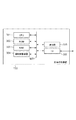
図1は、本実施形態に係る画像処理システムの構成を示すブロック図である。図1に示すように、画像処理システムは相互に通信可能な画像処理装置100及び撮像装置200を備える。なお、本実施形態では画像処理装置100と撮像装置200が別々のデバイスとして構成されている場合を中心に説明するが、画像処理装置100と撮像装置200が一体となって構成されていてもよい。
[System configuration]
FIG. 1 is a block diagram illustrating a configuration of an image processing system according to the present embodiment. As shown in FIG. 1, the image processing system includes an
撮像装置200は、撮像画像に基づいて視点情報を取得し、画像処理装置100に送信する。本実施形態における視点情報は、画像処理装置100によって生成される画像の視点を示す情報であり、例えば自由視点画像における視点の位置、視線の方向、視線を軸とする回転角などを示す情報である。画像処理装置100は、撮像装置200から受信した視点情報に基づく画像を出力する。なお、本実施形態における撮像装置200は、取得した視点情報を画像処理装置100に逐次送信する。ただしこれに限らず、撮像装置200は、一定期間にわたって取得した視点情報を記憶しておき、それらの視点情報をまとめて画像処理装置100に送信してもよい。画像処理装置100が出力する画像は動画であってもよいし、静止画であってもよい。また、撮像装置200から送信される視点情報に視点の位置に関する情報及び視線の方向に関する情報の少なくとも何れかが含まれず、画像処理装置100が予め設定された値をそれらの情報として代用するモードを有していてもよい。画像処理装置100の具体例はパーソナルコンピュータやスマートデバイスなどであり、撮像装置200の具体例はスマートデバイスやデジタルカメラなどである。
The
画像処理装置100は、送受信部101、方向特定部102、視点変換部103及び画像出力部104を備える。送受信部101は、撮像装置200から送信された視点情報を受信する。方向特定部102は、視点情報の基準となる座標系における基準方向を特定する。視点変換部103は、送受信部101が受信した視点情報を、方向特定部102が特定した基準方向に基づいて変換する。そして画像出力部104は、視点変換部103が変換した視点情報に基づく画像を生成して出力する。画像の出力先については限定しないが、画像出力部104は例えば液晶ディスプレイやプロジェクタ等の表示装置に画像を出力する。
The
方向特定部102が特定する基準方向は、画像出力部104が画像を生成する際に基準とする方向である。例えば、画像出力部104は自由視点画像の技術を用いて、視点情報の基準となる座標系に基づく仮想空間に、基準方向とオブジェクトに定められた鉛直下方向(重力方向)とが一致するようにオブジェクトを配置する。そして画像出力部104は、視点情報により特定される視点からそのオブジェクトを見た見えを表す画像を生成する。視点変換部103が視点情報を変換することにより、画像出力部104により生成される画像は、傾きが補正された画像、例えば画像の下方向(図5の例では画像410のy方向)と画像内における重力方向とが一致した画像となる。
The reference direction specified by the
なお本実施形態では、画像出力部104が、複数の方向から撮像された複数の撮像画像に基づく3Dモデルを上記のオブジェクトとして、画像を生成する場合を中心に説明する。ただしこれに限らず、上記のオブジェクトは、例えば撮像画像を用いずにCG(Computer Graphics)によって生成されたモデルであってもよい。
In the present embodiment, the case where the
撮像装置200は、撮像部201、視点取得部202及び送受信部203を備える。撮像部201は画像を撮像し、視点取得部202は、撮像部201が撮像した画像に基づいて視点情報を取得する。送受信部203は、視点取得部202が取得した視点情報を画像処理装置100に送信する。
The
次に、図2を用いて画像処理装置100のハードウェア構成について説明する。画像処理装置100は、CPU301、ROM302、RAM303、補助記憶装置304、操作部305、I/F(インターフェース)306及びバス307を備える。
Next, the hardware configuration of the
CPU301は、ROM302やRAM303に格納されているコンピュータプログラムやデータを用いて画像処理装置100全体の制御を行う。即ち、CPU301は、図1に示した画像処理装置100の各構成要素として機能する。ROM302は、変更を必要としないプログラムやパラメータを格納する。RAM303は、補助記憶装置304から供給されるプログラムやデータ、及びI/F306を介して外部から取得されたデータなどを一時的に記憶する。補助記憶装置304は、例えばハードディスクドライブ装置等で構成され、静止画や動画などのコンテンツデータを記憶する。
The
操作部305は、例えばキーボードやマウス等で構成され、ユーザーによる操作を受けて各種の指示をCPU301に入力する。I/F306には、LANやインターネット等のネットワーク、投影装置や表示装置等の他の機器を接続することができ、画像処理装置100はI/F306を介して様々な情報を取得したり送出したりすることができる。バス307は、上述の各部を繋いで情報を伝達する。
The
なお、本実施形態では操作部305が画像処理装置100の内部に存在するが、操作部305が画像処理装置100の外部に別の装置として存在していてもよい。この場合 、CPU301が、操作部305を制御する操作制御部として動作する。なお、画像処理装置100はCPU301を用いたソフトウェア処理の代替としてハードウェアによる処理を行ってもよく、この場合には画像処理装置100は図1の各構成要素に対応する演算部や回路を備える。
In the present embodiment, the
[画像処理装置100の処理フロー]
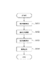
次に、画像処理装置100の処理フローについて説明する。図3は、画像処理装置100の動作を説明するためのフローチャートである。図3の処理は、画像処理装置100と撮像装置200との間で通信を行うための接続が確立されたタイミングで開始される。ただし、図3の処理の開始タイミングは上記タイミングに限定されない。図3の処理は、CPU301がROM302に格納されたプログラムをRAM303に展開して実行することで実現される。
[Processing Flow of Image Processing Apparatus 100]
Next, the processing flow of the
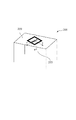
S401では、画像処理装置100の送受信部101が、撮像装置200から送信された視点情報を受信して取得する。ここで、撮像装置200が画像処理装置100に送信するための視点情報を取得する方法の一例を、図4を用いて説明する。撮像装置200は視点を指定するためにユーザーにより操作され、撮像部201は設置された2次元マーカー220を撮像する。視点取得部202は、その撮像画像に基づいて、2次元マーカー220を基準とした座標系230における撮像装置200の位置及び姿勢を算出する。そして送受信部203は、視点取得部202による算出結果に基づく撮像装置200の位置情報及び姿勢情報を視点情報として画像処理装置100に送信する。画像処理装置100の送受信部101は、撮像装置200の送受信部203が送信した位置情報及び姿勢情報を取得する。撮像装置200の位置情報は視点の位置を示す情報であり、撮像装置200の姿勢情報は視線の方向、及び視線を軸とする回転角を示す情報である。視線を軸とする回転角は、視界がどの程度回転しているか(傾いているか)を表すものである。2次元マーカー220を利用した撮像装置200の位置及び姿勢の算出には、公知の技術を用いることができる。
In step S <b> 401, the transmission /
S402では、方向特定部102が、視点情報の基準となる座標系における基準方向を特定する。図4の例では、座標系230が視点情報の基準となる座標系である。この場合に方向特定部102は、例えば座標系230のZ軸方向、すなわち2次元マーカー220に垂直な方向を基準方向として特定する。本実施形態では、方向特定部102により特定される基準方向が2次元マーカー220の面に対してどの方向であるかが、画像処理装置100に予め設定されているものとする。なお、方向特定部102は例えば、撮像装置200から画像処理装置100に送信された情報などに基づいて基準方向を特定してもよい。
In S402, the
なお、本実施形態では撮像装置200が画像処理装置100に視点情報を送信する場合を中心に説明するが、これに限らない。例えば、撮像装置200の送受信部203は、撮像部201がマーカーを撮像した撮像画像を画像処理装置100に送信してもよい。この場合、方向特定部102が、送受信部101が受信した撮像画像に基づいて視点情報を算出し、さらに基準方向を特定する。
In this embodiment, the case where the
S403では、視点変換部103が、方向特定部102が特定した基準方向に基づいて、送受信部101が取得した視点情報を変換する。視点情報の変換方法については後述する。
In step S <b> 403, the
S404では、画像出力部104が、視点変換部103により変換された視点情報に基づく画像を生成し出力する。ここで、画像処理装置100が自由視点画像の技術を用いて、仮想空間中に配置される仮想カメラによる撮像画像を出力する場合について、具体的に説明する。仮想カメラの位置及び姿勢は視点情報に基づいて定まり、被写体となるオブジェクトの仮想空間内における向きは基準方向に基づいて定まる。すなわち、仮想カメラによる撮像画像は、仮想空間内に基準方向に基づいて配置されるオブジェクトを視点情報により特定される視点から見た見えを表す特定視点画像となる。まず画像出力部104は、複数の方向から撮像された複数の撮像画像を、撮像装置200とは異なる外部の装置から取得する。そして画像出力部104は、外部の装置から取得した撮像画像と、送受信部101が取得して視点変換部103が変換した視点情報とに基づいて、特定視点画像を生成する。視点変換部103による変換処理は、送受信部101が取得した視点情報に含まれる特定視点画像の傾きに関する情報を補正するための処理である。視点変換部103が変換処理を行うことによって、画像出力部104は視点情報に基づく傾きが補正された特定視点画像を生成することができる。最後に画像出力部104は、生成した特定視点画像を出力する。
In step S <b> 404, the
なお、画像出力部104は、複数の方向から撮像された複数の撮像画像を取得する代わりに、複数の撮像画像から生成された3Dモデルのデータを取得し、そのモデルと視点情報と基づいて特定視点画像を生成してもよい。また、画像出力部104は、撮像画像を用いずにCGによって生成されたモデルと視点情報とに基づいて特定視点画像を生成してもよい。
The
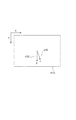
以上で画像処理装置100の処理フローについての説明を終わる。次に、視点変換部103による視点情報の変換について、図5を用いて説明する。画像410は、画像処理装置に100により生成される、仮想カメラによる撮像画像(特定視点画像)の例である。
This is the end of the description of the processing flow of the
視点変換部103は、方向特定部102が特定した基準方向420が画像410において目標方向430に近づくように、送受信部101が取得した視点情報を変換する。目標方向430は特定視点画像の所定方向であり、図5の例では下方向(y方向)である。本実施形態において目標方向430は画像処理装置100に予め設定されているものとするが、これに限らず、例えばユーザーが指定する方向であってもよい。変換後の視点情報に基づく特定視点画像は、画像出力部104により出力される画像となる。なお、本実施形態において基準方向420と目標方向430とが近づくとは、基準方向420に対応するベクトルと目標方向430に対応するベクトルとが成す角の大きさが小さくなることである。これは、基準方向420と目標方向430とが一致することも含む。
The
本実施形態を適用する状況の具体例として、撮像装置200により2次元マーカー220が撮像された撮像画像から座標系230を基準とする視点情報が取得され、基準方向420が座標系230におけるZ軸方向である場合を考える。画像処理装置100は自由視点画像の技術を用いて、基準方向420が特定視点画像の画像内における重力方向となるように、複数の方向から撮像された複数の撮像画像を合成して画像410を生成する。
As a specific example of the situation to which the present embodiment is applied, viewpoint information based on the coordinate
ここで、水平に設置された表示装置に出力された画像410をユーザーが見ることを考えると、ユーザーにとっての見やすさの観点から、表示装置の下方向と画像410内における重力方向とが一致していることが望ましい。そこで本実施形態では、目標方向430を特定視点画像の下方向とする。そして視点変換部103は、視点情報に基づく傾きを補正するための処理として、特定視点画像の画像内における重力方向に対応する基準方向420と目標方向430とが近づくように視点情報を変換する。視点情報に基づく傾きは、基準方向420と目標方向430とのずれによる特定視点画像の傾きであり、例えば撮像装置200による撮像画像内における2次元マーカー220の傾きに基づいて定まる。
Here, considering that the user views the
次に、画像410内における基準方向420を目標方向430に一致させる場合の、視点変換部103による視点情報の変換方法の例を具体的に説明する。S401において送受信部101が取得した視点情報は、行列Pを用いて表現される。行列Pは3行4列の行列であり、3行3列の回転行列Rと3行1列の並進ベクトルTで構成される。S402において方向特定部102が特定した基準方向420は、3次元の単位ベクトルAを用いて表現される。
Next, an example of the viewpoint information conversion method by the
まず、変換前の視点情報に基づく特定視点画像である画像410内における基準方向420に対応する角度αを計算する。画像410内における方向は、画像410の右方向を0(ゼロ)[rad]として時計回りを正とする−π〜π[rad]の範囲の角度で表される。角度αに対応する2次元ベクトルの画像410における左右方向の成分をAx、上下方向の成分をAyとすると、角度αは式(1)及び式(2)によって計算される。
First, the angle α corresponding to the

式(1)では、視点情報の基準となる座標系における基準方向420を表す単位ベクトルAが、回転行列Rを掛けることで、視点情報から特定される視点(仮想カメラ)を基準とする座標系におけるベクトルに変換される。視点情報の基準となる座標系は、例えば2次元マーカー220を基準とする座標系230である。式(1)において、sはスケールファクタである。式(2)では、式(1)によって求まるAxとAyから、角度αが計算される。
In equation (1), a unit vector A representing a
次に、基準方向420と目標方向430との間のずれをなくすための視点情報の変換に係る変換行列を計算する。画像410内における目標方向430に対応する角度を角度βとする。また、目標方向430に対応する角度βと基準方向420に対応する角度αとの差を角度γ=(β−α)で表わす。角度γの差を補正するための視点情報の変換は、視点情報から特定される視線の方向(特定される視点を基準とする座標系におけるz軸方向)を軸とした回転を表す3行3列の回転行列R’によって、式(3)のように表わされる。
Next, a transformation matrix related to transformation of viewpoint information for eliminating a deviation between the
最後に、送受信部101が取得した視点情報を表す行列Pを式(4)のように回転行列R’によって変換し、変換後の視点情報を表す行列P’を計算する。
Finally, the matrix P representing the viewpoint information acquired by the transmission /
![]()
以上のように、視点変換部103は、送受信部101が取得した視点情報に対して、回転行列R’によって表される、視線を軸とする回転角に関する変換を行う。この変換により、視点情報に基づく画像410の傾きが補正される。その結果、行列P’によって表される変換後の視点情報に基づく特定視点画像において、基準方向420と目標方向430とが一致する。
![]()
As described above, the
以上説明したように、本実施形態における画像処理装置100は、視点を示す視点情報を取得し、取得した視点情報に基づいて特定視点画像を生成し出力する。この特定視点画像の生成にあたって画像処理装置100は、視点情報に基づく傾きを補正するための処理を行う。これにより画像処理装置100は、視点を示す情報に基づく画像を出力する場合に、出力される画像の見やすさを向上させることができる。
As described above, the
[傾き補正の程度の調整]
上記において、画像処理装置100が出力画像内における基準方向を目標方向に一致させる場合の例を説明したが、画像処理装置100は出力画像において基準方向と目標方向とが近づくような制御を行えばよい。例えば、視点変換部103は送受信部101が取得した視点情報から視線の方向を特定する。そして視点変換部103は、視線の方向と方向特定部102が特定した基準方向との関係に応じた程度で傾きを補正するための処理を行って特定視点画像を生成してもよい。このような制御により、出力画像内における基準方向と目標方向とを常に一致させる場合よりも、出力画像がユーザーにとってより見やすい画像となる場合がある。
[Adjusting the degree of tilt correction]
In the above description, the example in which the
ここで、画像処理装置100が自由視点画像の技術を用いて、方向特定部102が特定した基準方向が特定視点画像の画像内における重力方向となるように、特定視点画像を生成する場合を考える。また、目標方向は特定視点画像の下方向とする。
Here, consider a case where the
基準方向と視線の方向との関係が垂直に近い場合、出力される特定視点画像の傾きが変化すると、ユーザーにとっては画像内の重力が働く向きが変化したように見えてしまい、ユーザーが感じる違和感が大きい。そのため画像処理装置100は、特定視点画像において基準方向と目標方向とができるだけ近づくように制御を行うことで、出力画像をユーザーにとって見やすい画像とすることができる。
When the relationship between the reference direction and the direction of the line of sight is close to vertical, if the tilt of the output specific viewpoint image changes, it will appear to the user as if the direction in which the gravity in the image changes changes, and the user feels uncomfortable. Is big. Therefore, the
一方、基準方向と視線の方向との関係が平行に近い場合、特定視点画像は仮想カメラがオブジェクトを真上又は真下に近い角度から撮像した画像となるため、出力される特定視点画像の傾きが変化してもユーザーが感じる違和感は少ない。また、この場合に基準方向と目標方向とを常に一致させるような制御が行われると、仮想カメラの位置や姿勢が少し変化しただけで画像が大きく変化することがあり、結果としてユーザーにとって出力画像が見づらくなる。 On the other hand, when the relationship between the reference direction and the direction of the line of sight is close to parallel, the specific viewpoint image is an image in which the virtual camera captures the object from an angle close to directly above or directly below. Even if it changes, there is little discomfort felt by the user. In this case, if control is performed so that the reference direction always matches the target direction, the image may change significantly even if the position and orientation of the virtual camera change slightly, resulting in an output image for the user. Is difficult to see.
以上のことを考慮して、画像処理装置100は、基準方向と視線の方向とが平行に近い場合には、視点情報に基づく傾きを補正する程度を小さくしてもよい。以下、この場合の視点情報の変換方法の例を具体的に説明する。
Considering the above, the
視点変換部103は、送受信部101が取得した視点情報から、視線の方向、及び視線を軸とする回転角を特定する。基準方向に対応する3次元の単位ベクトルと視線の方向に対応する3次元の単位ベクトルとが成す角の大きさをθとする。視点変換部103により特定される回転角は視界の傾きを表すものであり、基準方向と目標方向とのずれを表す上述の角度γは、視点変換部103が特定した回転角に基づいて定まる。
The
まず、基準方向と視線の方向との関係における垂直度合いを表す係数kが式(5)のように計算される。係数kは、基準方向と視線の方向とが平行の場合に0、垂直の場合に1となる係数となる。そして、視点変換部103による視点情報の変換を表す回転行列R’が式(6)に基づいて計算される。
First, a coefficient k representing the degree of perpendicularity in the relationship between the reference direction and the line-of-sight direction is calculated as shown in Equation (5). The coefficient k is a coefficient that is 0 when the reference direction and the direction of the line of sight are parallel, and 1 when the direction is vertical. Then, a rotation matrix R ′ representing the conversion of viewpoint information by the
変換後の視点情報を表す行列P’は、式(6)で計算された回転行列R’を式(4)に適用することによって計算される。なお、視点情報の変換の程度を調整するための係数kは式(5)で定められるものに限らない。例えば式(7)に示すように、基準方向と視線の方向とがなす角の大きさに比例するように係数kが定められても良い。
The matrix P ′ representing the converted viewpoint information is calculated by applying the rotation matrix R ′ calculated in Expression (6) to Expression (4). Note that the coefficient k for adjusting the degree of conversion of the viewpoint information is not limited to that defined by the equation (5). For example, as shown in Expression (7), the coefficient k may be determined so as to be proportional to the size of the angle formed by the reference direction and the direction of the line of sight.
式(7)において、係数aは例えば、基準方向と視線の方向とが垂直の場合にk=1、平行の場合にk=0となるような係数a=2/πである。
In equation (7), the coefficient a is, for example, a coefficient a = 2 / π such that k = 1 when the reference direction and the direction of the line of sight are perpendicular and k = 0 when parallel.
また係数kは、式(5)や式(7)で定まるものの他にも例えば、θの値が所定の範囲内である場合はk=1となり、θの値が所定の範囲外である場合には0≦k<1となるような係数であってもよい。即ち、視点変換部103は、θが所定の範囲内である場合に、θが所定の範囲外である場合よりも、視線を軸とする回転角に基づく特定視点画像の傾きをより大きく補正してもよい。
In addition to the coefficient k determined by Equation (5) or Equation (7), for example, when the value of θ is within a predetermined range, k = 1, and when the value of θ is outside the predetermined range. May be a coefficient such that 0 ≦ k <1. That is, the
以上のように、視点変換部103は、基準方向と視線の方向との関係に応じて、特定視点画像の傾き補正の程度を調整する。これにより画像処理装置100は、基準方向に対する視線の方向が変化しても、ユーザーにとって違和感の少ない画像を出力することができる。以上で、傾き補正の程度の調整に関する説明を終わる。
As described above, the
なお、本実施形態では、視点変換部103が送受信部101により取得された視点情報に対して視線を軸とする回転角に関する変換を行い、画像出力部104が変換後の視点情報に基づく画像を生成して出力する場合を中心に説明した。しかしこれに限らず、視点変換部103は視点情報を変換する処理を行わず、代わりに画像出力部104が画像を回転する処理を行ってもよい。具体的には、画像出力部104は、送受信部101が取得した視点情報を用いて、複数の方向から撮像された複数の撮像画像を合成し、傾きが補正されていない第1の特定視点画像を生成する。そして画像出力部104は、第1の特定視点画像を回転させる処理を行って、傾きが第1の特定視点画像よりも補正された第2の特定視点画像を生成し出力する。第1の特定視点画像をどの程度回転させるかは視点情報及び基準方向に基づいて決定される。例えば画像出力部104は、目標方向と基準方向とのずれを表す上述の角度γだけ画像を回転させてもよい。なお画像出力部104は、第1の特定視点画像を回転させる処理を行って第2の特定視点画像を生成するにあたって、画像の形状が適切になるように、回転に加え画像を変形させる処理を行ってもよい。
In the present embodiment, the
また、方向特定部102が特定する基準方向は上記で説明したものに限定されない。例えば、撮像装置200が重力センサを備えており、重力センサの計測結果を視点情報と共に画像処理装置100に送信する。そして方向特定部102は、撮像装置200から受信した重力センサの計測結果と視点情報とに基づいて、視点情報の基準となる座標系における、計測結果が示す重力の方向を、基準方向として特定してもよい。この場合、撮像装置200の水平からの傾きに基づいて、特定視点画像の傾きが定まる。また、基準方向はユーザーにより指定される任意の方向でもよい。さらに、視点情報に基づく傾きを補正するための処理は、特定視点画像の下方向(y方向)と特定視点画像の画像内における重力方向とを近づける処理には限定されない。例えば、出力画像内のオブジェクトに固有の方向を、出力画像の所定の方向に近づける処理であってもよい。オブジェクトに固有の方向とは、人型のオブジェクトが立つ面に対する垂直方向など、オブジェクトの向きや形状に基づいて定まる方向である。
Further, the reference direction specified by the
また本実施形態では、画像処理装置100が、ユーザーにより操作される機器の位置情報及び姿勢情報を、視点の位置、視線の方向、及び視線を軸とする回転角を示す視点情報として取得する場合を中心に説明した。具体的には、ユーザーにより操作される撮像装置200が、撮像画像から算出した撮像装置200の位置及び姿勢を画像処理装置100に視点情報として送信し、画像処理装置100がその視点情報を受信して取得する。この方法によれば、ユーザーは機器を物理的に操作することで、直観的に視点を指定することができる。
In this embodiment, the
なお、ユーザーにより操作される機器は撮像装置200に限らず、ユーザーは6自由度のセンサ(例えばGPSセンサと角度センサ)を備えた装置を操作し、画像処理装置100はセンサの計測結果を視点情報として取得しても良い。また、ユーザーは固定されたカメラの撮像範囲内においてマーカーを有する物体を操作し、画像処理装置100は固定カメラによる撮像画像に基づいて算出されたマーカーの位置と姿勢を視点情報として取得しても良い。また、ユーザーはロボットを操作し、画像処理装置100はそのロボットの各関節の角度を視点情報として取得してもよい。さらに、画像処理装置100は、ユーザーによる機器の操作に基づく視点情報に限らず、ユーザーによる数値の指定やその他の方法によって生成された視点情報を取得してもよい。
Note that the device operated by the user is not limited to the
視点情報がいずれの方法で取得された場合であっても、画像処理装置100は、その視点情報に基づく傾きを補正するための処理を行って特定視点画像を生成する。これにより、出力される特定視点画像の傾きが小さくなり、出力画像のユーザーにとっての見やすさが向上する。特に、ユーザーが機器を物理的に操作してその位置及び姿勢に基づいて視点を指定する場合、機器を意図通りに正確に操作するのは困難であると考えられる。そのような場合でも、本実施形態の技術を用いれば、出力画像の傾きを適切に制御することができる。
Regardless of the method for acquiring the viewpoint information, the
<その他の実施形態>
本発明は、上述の実施形態の1以上の機能を実現するプログラムを、ネットワーク又は記憶媒体を介してシステム又は装置に供給し、そのシステム又は装置のコンピュータにおける1つ以上のプロセッサーがプログラムを読出し実行する処理でも実現可能である。また、1以上の機能を実現する回路(例えば、ASIC等)によっても実現可能である。また、そのプログラムをコンピュータにより読み取り可能な記録媒体に記録して提供してもよい。
<Other embodiments>
The present invention supplies a program that realizes one or more functions of the above-described embodiments to a system or apparatus via a network or a storage medium, and one or more processors in a computer of the system or apparatus read and execute the program This process can be realized. It can also be realized by a circuit (for example, ASIC) that realizes one or more functions. Further, the program may be provided by being recorded on a computer-readable recording medium.
100 画像処理装置
101 送受信部
102 方向特定部
103 視点変換部
104 画像出力部
DESCRIPTION OF
Claims (13)
前記取得手段が取得した視点情報に基づいて特定視点画像を生成する生成手段であって、前記視点情報に基づく傾きを補正するための処理を行って前記特定視点画像を生成する生成手段と、
前記生成手段が生成した前記特定視点画像を出力する出力手段とを有することを特徴とする画像処理装置。 Acquisition means for acquiring viewpoint information indicating a viewpoint;
Generation means for generating a specific viewpoint image based on the viewpoint information acquired by the acquisition means, the generation means for generating the specific viewpoint image by performing processing for correcting a tilt based on the viewpoint information;
An image processing apparatus comprising: output means for outputting the specific viewpoint image generated by the generation means.
前記生成手段は、前記基準方向と前記特定手段が特定した視線の方向との関係に応じた程度で前記傾きを補正するための処理を行って前記特定視点画像を生成することを特徴とする請求項2又は3に記載の画像処理装置。 A specifying unit that specifies the direction of the line of sight from the viewpoint information acquired by the first acquiring unit;
The generation unit generates the specific viewpoint image by performing a process for correcting the tilt to a degree corresponding to a relationship between the reference direction and the direction of the line of sight specified by the specifying unit. Item 4. The image processing apparatus according to Item 2 or 3.
前記生成手段は、前記基準方向に対応するベクトルと前記特定手段が特定した視線の方向に対応するベクトルとが成す角の大きさが所定の範囲内である場合に、前記角の大きさが前記所定の範囲外である場合よりも、前記回転角に基づく前記傾きをより大きく補正するための処理を行って前記特定視点画像を生成することを特徴とする請求項4に記載の画像処理装置。 The specifying means specifies a rotation angle about the line of sight from the viewpoint information acquired by the first acquisition means,
The generating means is configured such that when the magnitude of an angle formed by a vector corresponding to the reference direction and a vector corresponding to the direction of the line of sight specified by the specifying means is within a predetermined range, The image processing apparatus according to claim 4, wherein the specific viewpoint image is generated by performing a process for correcting the inclination based on the rotation angle to be larger than that in a case outside a predetermined range.
前記出力手段は、前記生成手段が生成した前記第2の特定視点画像を出力することを特徴とする請求項1乃至5の何れか1項に記載の画像処理装置。 The generation means generates a first specific viewpoint image based on the viewpoint information acquired by the first acquisition means, performs a process of rotating the first specific viewpoint image, and the inclination is the first specific viewpoint. Generating a second specific viewpoint image corrected from the image;
The image processing apparatus according to claim 1, wherein the output unit outputs the second specific viewpoint image generated by the generation unit.
前記視点情報に基づく前記傾きは、前記撮像画像内におけるマーカーの傾きに基づいて定まることを特徴とする請求項1乃至8の何れか1項に記載の画像処理装置。 The first acquisition unit acquires the viewpoint information based on a captured image in which a marker is captured,
The image processing apparatus according to claim 1, wherein the inclination based on the viewpoint information is determined based on an inclination of a marker in the captured image.
前記生成手段は、前記取得手段が取得した視点情報と前記第2取得手段が取得した撮像画像とに基づいて前記特定視点画像を生成することを特徴とする請求項1乃至9の何れか1項に記載の画像処理装置。 Having a second acquisition means for acquiring a plurality of captured images imaged from a plurality of directions;
The said generation means produces | generates the said specific viewpoint image based on the viewpoint information which the said acquisition means acquired, and the captured image which the said 2nd acquisition means acquired, The any one of Claim 1 thru | or 9 characterized by the above-mentioned. An image processing apparatus according to 1.
前記第1取得工程において取得された視点情報に基づいて特定視点画像を生成する生成工程であって、前記視点情報に基づく傾きを補正するための処理を行って前記特定視点画像を生成する生成工程と、
前記生成工程において生成された特定視点画像を出力する出力工程とを有することを特徴とする画像処理方法。 A first acquisition step of acquiring viewpoint information indicating a viewpoint;
A generation step of generating a specific viewpoint image based on the viewpoint information acquired in the first acquisition step, wherein the generation step of generating the specific viewpoint image by performing a process for correcting an inclination based on the viewpoint information When,
And an output step of outputting the specific viewpoint image generated in the generation step.
Priority Applications (2)
| Application Number | Priority Date | Filing Date | Title |
|---|---|---|---|
| JP2016016372A JP2017134775A (en) | 2016-01-29 | 2016-01-29 | Image processing apparatus, image processing method, and program |
| US15/414,340 US10218920B2 (en) | 2016-01-29 | 2017-01-24 | Image processing apparatus and control method for generating an image by viewpoint information |
Applications Claiming Priority (1)
| Application Number | Priority Date | Filing Date | Title |
|---|---|---|---|
| JP2016016372A JP2017134775A (en) | 2016-01-29 | 2016-01-29 | Image processing apparatus, image processing method, and program |
Related Child Applications (1)
| Application Number | Title | Priority Date | Filing Date |
|---|---|---|---|
| JP2020123244A Division JP7030906B2 (en) | 2020-07-17 | 2020-07-17 | Information processing equipment, information processing methods and programs |
Publications (2)
| Publication Number | Publication Date |
|---|---|
| JP2017134775A true JP2017134775A (en) | 2017-08-03 |
| JP2017134775A5 JP2017134775A5 (en) | 2019-03-07 |
Family
ID=59385838
Family Applications (1)
| Application Number | Title | Priority Date | Filing Date |
|---|---|---|---|
| JP2016016372A Pending JP2017134775A (en) | 2016-01-29 | 2016-01-29 | Image processing apparatus, image processing method, and program |
Country Status (2)
| Country | Link |
|---|---|
| US (1) | US10218920B2 (en) |
| JP (1) | JP2017134775A (en) |
Cited By (1)
| Publication number | Priority date | Publication date | Assignee | Title |
|---|---|---|---|---|
| EP4054186A1 (en) | 2021-02-26 | 2022-09-07 | Canon Kabushiki Kaisha | Information processing apparatus, information processing method, and program |
Families Citing this family (2)
| Publication number | Priority date | Publication date | Assignee | Title |
|---|---|---|---|---|
| JP2019125303A (en) * | 2018-01-19 | 2019-07-25 | キヤノン株式会社 | Information processing device, information processing method, and program |
| CN110766807B (en) * | 2019-09-25 | 2023-02-03 | 稿定(厦门)科技有限公司 | 3D graph rotation method, medium, device and apparatus |
Citations (5)
| Publication number | Priority date | Publication date | Assignee | Title |
|---|---|---|---|---|
| JP2003204547A (en) * | 2001-10-15 | 2003-07-18 | Matsushita Electric Ind Co Ltd | Vehicle surrounding monitoring system and method for adjusting the same |
| JP2013017165A (en) * | 2011-06-10 | 2013-01-24 | Panasonic Corp | Imaging apparatus |
| JP2013061870A (en) * | 2011-09-14 | 2013-04-04 | Namco Bandai Games Inc | Program, information storage medium, and electronic device |
| JP2013214252A (en) * | 2012-04-04 | 2013-10-17 | Nintendo Co Ltd | Display control system, display control method, display control program, and display control device |
| WO2015087730A1 (en) * | 2013-12-10 | 2015-06-18 | 株式会社日立国際電気 | Monitoring system |
Family Cites Families (6)
| Publication number | Priority date | Publication date | Assignee | Title |
|---|---|---|---|---|
| WO2006025137A1 (en) * | 2004-09-01 | 2006-03-09 | Sony Computer Entertainment Inc. | Image processor, game machine, and image processing method |
| JP5756322B2 (en) * | 2011-04-08 | 2015-07-29 | 任天堂株式会社 | Information processing program, information processing method, information processing apparatus, and information processing system |
| JP5559765B2 (en) * | 2011-12-14 | 2014-07-23 | 株式会社コナミデジタルエンタテインメント | GAME DEVICE AND PROGRAM |
| US9286725B2 (en) * | 2013-11-14 | 2016-03-15 | Nintendo Co., Ltd. | Visually convincing depiction of object interactions in augmented reality images |
| JP6674192B2 (en) * | 2014-05-28 | 2020-04-01 | ソニー株式会社 | Image processing apparatus and image processing method |
| US9754416B2 (en) * | 2014-12-23 | 2017-09-05 | Intel Corporation | Systems and methods for contextually augmented video creation and sharing |
-
2016
- 2016-01-29 JP JP2016016372A patent/JP2017134775A/en active Pending
-
2017
- 2017-01-24 US US15/414,340 patent/US10218920B2/en active Active
Patent Citations (5)
| Publication number | Priority date | Publication date | Assignee | Title |
|---|---|---|---|---|
| JP2003204547A (en) * | 2001-10-15 | 2003-07-18 | Matsushita Electric Ind Co Ltd | Vehicle surrounding monitoring system and method for adjusting the same |
| JP2013017165A (en) * | 2011-06-10 | 2013-01-24 | Panasonic Corp | Imaging apparatus |
| JP2013061870A (en) * | 2011-09-14 | 2013-04-04 | Namco Bandai Games Inc | Program, information storage medium, and electronic device |
| JP2013214252A (en) * | 2012-04-04 | 2013-10-17 | Nintendo Co Ltd | Display control system, display control method, display control program, and display control device |
| WO2015087730A1 (en) * | 2013-12-10 | 2015-06-18 | 株式会社日立国際電気 | Monitoring system |
Non-Patent Citations (2)
| Title |
|---|
| 大川原 友樹、外3名: ""ユーザの仮想カメラ操作を考慮した位置姿勢補正による自由視点映像の生成"", 電子情報通信学会技術研究報告, vol. 113, no. 470, JPN6019049814, 27 February 2014 (2014-02-27), JP, pages 261 - 266, ISSN: 0004179005 * |
| 谷藤 誠、菅谷 保之: ""複合現実感システムのためのテクスチャの局所特徴を用いたマーカー識別と方向推定"", 画像の認識・理解シンポジウム(MIRU2011)論文集, vol. 2011, JPN6019049812, 20 July 2011 (2011-07-20), JP, pages 1161 - 1168, ISSN: 0004179004 * |
Cited By (2)
| Publication number | Priority date | Publication date | Assignee | Title |
|---|---|---|---|---|
| EP4054186A1 (en) | 2021-02-26 | 2022-09-07 | Canon Kabushiki Kaisha | Information processing apparatus, information processing method, and program |
| US11847735B2 (en) | 2021-02-26 | 2023-12-19 | Canon Kabushiki Kaisha | Information processing apparatus, information processing method, and recording medium |
Also Published As
| Publication number | Publication date |
|---|---|
| US10218920B2 (en) | 2019-02-26 |
| US20170223281A1 (en) | 2017-08-03 |
Similar Documents
| Publication | Publication Date | Title |
|---|---|---|
| US11914147B2 (en) | Image generation apparatus and image generation method using frequency lower than display frame rate | |
| US11151790B2 (en) | Method and device for adjusting virtual reality image | |
| KR102046032B1 (en) | Image capturing apparatus, image capture system, image processing method, information processing apparatus, and computer-readable storage medium | |
| JP3805231B2 (en) | Image display apparatus and method, and storage medium | |
| JP4677281B2 (en) | Image processing method and image processing apparatus | |
| US20170078570A1 (en) | Image processing device, image processing method, and image processing program | |
| JPWO2021076757A5 (en) | ||
| JP2017134775A (en) | Image processing apparatus, image processing method, and program | |
| JP2008146497A (en) | Image processor and image processing method | |
| US10901213B2 (en) | Image display apparatus and image display method | |
| JP2020129823A (en) | Image capturing apparatus, image capturing system, image processing method, information processing apparatus, and program | |
| KR20130130283A (en) | System for generating a frontal-view image for augmented reality based on the gyroscope of smart phone and method therefor | |
| JP2017166993A (en) | Arithmetic device, control device, and program | |
| JP7030906B2 (en) | Information processing equipment, information processing methods and programs | |
| CN114201028B (en) | Augmented reality system and method for anchoring display virtual object thereof | |
| US20180278902A1 (en) | Projection device, content determination device and projection method | |
| JP2021131490A (en) | Information processing device, information processing method, and program | |
| WO2015141214A1 (en) | Processing device for label information for multi-viewpoint images and processing method for label information | |
| JP2015201734A (en) | Image processing system, control method of the same, and program | |
| TW202040506A (en) | Virtual reality view compensation method, non-transitory computer readable medium and virtual reality device | |
| JP7465133B2 (en) | Information processing device and information processing method | |
| US11954269B2 (en) | Information processing apparatus, information processing method, and program for generating location data | |
| WO2021075113A1 (en) | Information processing device, information processing method, and program | |
| CN108090933B (en) | Two-dimensional plane calibration method and device | |
| CN113168191A (en) | Holder control method, handheld holder and computer readable storage medium |
Legal Events
| Date | Code | Title | Description |
|---|---|---|---|
| A521 | Request for written amendment filed |
Free format text: JAPANESE INTERMEDIATE CODE: A523 Effective date: 20190124 |
|
| A621 | Written request for application examination |
Free format text: JAPANESE INTERMEDIATE CODE: A621 Effective date: 20190124 |
|
| A977 | Report on retrieval |
Free format text: JAPANESE INTERMEDIATE CODE: A971007 Effective date: 20191213 |
|
| A131 | Notification of reasons for refusal |
Free format text: JAPANESE INTERMEDIATE CODE: A131 Effective date: 20191224 |
|
| A521 | Request for written amendment filed |
Free format text: JAPANESE INTERMEDIATE CODE: A523 Effective date: 20200221 |
|
| A02 | Decision of refusal |
Free format text: JAPANESE INTERMEDIATE CODE: A02 Effective date: 20200421 |