JP2017134747A - Farm work management system - Google Patents

Farm work management system Download PDF

Info

Publication number
JP2017134747A
JP2017134747A JP2016015933A JP2016015933A JP2017134747A JP 2017134747 A JP2017134747 A JP 2017134747A JP 2016015933 A JP2016015933 A JP 2016015933A JP 2016015933 A JP2016015933 A JP 2016015933A JP 2017134747 A JP2017134747 A JP 2017134747A
Authority
JP
Japan
Prior art keywords
work
plan
data
agricultural machine
information management
Prior art date
Legal status (The legal status is an assumption and is not a legal conclusion. Google has not performed a legal analysis and makes no representation as to the accuracy of the status listed.)
Pending
Application number
JP2016015933A
Other languages
Japanese (ja)
Inventor
吉邨 文夫
Fumio Yoshimura
文夫 吉邨
Current Assignee (The listed assignees may be inaccurate. Google has not performed a legal analysis and makes no representation or warranty as to the accuracy of the list.)
Iseki and Co Ltd
Iseki Agricultural Machinery Mfg Co Ltd
Original Assignee
Iseki and Co Ltd
Iseki Agricultural Machinery Mfg Co Ltd
Priority date (The priority date is an assumption and is not a legal conclusion. Google has not performed a legal analysis and makes no representation as to the accuracy of the date listed.)
Filing date
Publication date
Application filed by Iseki and Co Ltd, Iseki Agricultural Machinery Mfg Co Ltd filed Critical Iseki and Co Ltd
Priority to JP2016015933A priority Critical patent/JP2017134747A/en
Publication of JP2017134747A publication Critical patent/JP2017134747A/en
Pending legal-status Critical Current

Links

Images

Landscapes

  • Management, Administration, Business Operations System, And Electronic Commerce (AREA)

Abstract

PROBLEM TO BE SOLVED: To guarantee planned farm work execution by discriminating whether work can be started or executed in accordance with a work content or a work plan.SOLUTION: In a farm work management system, an agricultural machine comprises an information management terminal 91 which acquires various work data of the agricultural machine or positional information of the agricultural machine, and a work plan is introduced being inputted directly or through a net line or the like to a portable terminal 92 that is provided communicable with the information management terminal 91. Work suitability discrimination means T is configured to determine whether work is suitable for a predetermined work plan when starting work by an agricultural machine in accordance with data relating to the agricultural machine, the various work data and the positional data that are acquired by the information management terminal 91. If it is determined by the work suitability discrimination means T that the work is not suitable, work interruption is output or an alarm is output.SELECTED DRAWING: Figure 8

Description

この発明は、例えば、トラクタ、田植機、防除作業機等移動する農用作業機を使用する際の農作業管理システムに関する。   The present invention relates to a farm work management system when a moving farm work machine such as a tractor, a rice transplanter, or a control work machine is used.

例えば、圃場で行う作業内容や作業計画を記憶する記憶手段と、携帯端末からの要求を受けて取得した作業内容及び/又は作業計画を表示する手段を備えた構成の開示があり、農作業者は、作業内容又は作業計画を見て、農作業を行うことができる(特許文献1)。   For example, there is a disclosure of a configuration including storage means for storing work contents and work plans to be performed on a farm field, and means for displaying work contents and / or work plans acquired in response to a request from a mobile terminal. Agricultural work can be performed by looking at the work content or work plan (Patent Document 1).

特開2015−49872号公報JP 2015-49872 A

ところで上記各特許文献において、要求通りに作業内容や作業計画を取得しその表示を確認しながら作業を進める場合、表示内容と異なる作業工程を開始する場合があり、このような場合には対応できない。   By the way, in each of the above patent documents, when the work content or work plan is acquired as requested and the work is proceeded while confirming the display, a work process different from the display content may be started. .

本発明は、上記に鑑み農作業管理システムに作業計画における作業適否判定手段を構成し、作業内容や作業計画に沿った作業を開始し又は実行できるか否かを判定することによって計画的な農作業の実行を保証しようとする。   In view of the above, the present invention configures the work suitability determination means in the work plan in the farm work management system, and determines whether or not the work according to the work content or the work plan can be started or executed. Try to guarantee execution.

本発明の上記課題は次の解決手段により解決される。   The above-described problems of the present invention are solved by the following solution means.

請求項1記載の発明は、農業機械に当該農業機械の各種作業データや農業機械の位置情報を取得する情報管理端末91を備え、この情報管理端末91と通信可能に設ける携帯端末92に、直接入力し又はネット回線等を経由することにより作業計画を導入する農作業管理システムにおいて、上記情報管理端末91に取得された農業機械に関するデータ、上記各種作業データおよび位置データにより農業機械による作業開始の際に所定の作業計画に対する作業適否を判断する作業適否判定手段Tを構成し、作業適否判定手段Tにより不適と判断された場合に作業中断出力又は警報出力するよう構成した農作業管理システムとする。   The invention described in claim 1 includes an information management terminal 91 for acquiring various work data of the agricultural machine and position information of the agricultural machine in the agricultural machine, and is directly connected to the portable terminal 92 provided to be communicable with the information management terminal 91. In a farm work management system that introduces a work plan by inputting or via a network or the like, when the work is started by the farm machine using the data related to the farm machine acquired by the information management terminal 91, the various work data, and the position data. The farm work management system is configured such that the work suitability determination means T for judging work suitability for a predetermined work plan is configured, and when the work suitability judgment means T determines that the work suitability is inappropriate, the work interruption output or warning output is provided.

請求項2に記載の発明は、請求項1において、作業適否判定手段Tは、農業機械が所定の作業計画の対象圃場であるか否かを判定する圃場進入判定手段Xである。したがって、携帯端末92に圃場進入適否判定手段Xを予め導入しておき、情報管理端末91からの情報に基づいて、圃場進入適否判定手段Xが作業計画と異なる圃場と判定するときには、携帯端末92から情報管理端末91にブザー等の警報出力を出力する。   According to a second aspect of the present invention, in the first aspect, the work suitability determining means T is a field entry determining means X for determining whether or not the agricultural machine is a target field for a predetermined work plan. Therefore, when the field entry suitability determination means X is introduced in advance into the portable terminal 92 and the field entry suitability determination means X determines that the field is different from the work plan based on the information from the information management terminal 91, the portable terminal 92 Outputs an alarm output such as a buzzer to the information management terminal 91.

請求項3に記載の発明は、請求項1において、作業適否判定手段Tは、作業機器選択適否判定手段Yである。したがって、取り扱う農業機械自体が当該記憶された農業機械と異なる場合、あるいは使用する農作業機が異なる場合、すなわち前記農機名や作業機名が情報管理端末91に記憶されたものと異なる場合、作業機器選択適否判定手段Yが作業計画と異なる圃場と判定するときには、携帯端末92から情報管理端末91にブザー等の警報出力を出力する。   According to a third aspect of the present invention, in the first aspect, the work suitability determination means T is a work equipment selection suitability determination means Y. Therefore, when the agricultural machine to be handled is different from the stored agricultural machine, or when the agricultural machine to be used is different, that is, when the agricultural machine name and the working machine name are different from those stored in the information management terminal 91, the working equipment When the selection suitability determination means Y determines that the field is different from the work plan, an alarm output such as a buzzer is output from the portable terminal 92 to the information management terminal 91.

請求項4に記載の発明は、請求項1において、作業適否判定手段Tは、作業内容選択適否判定手段Zである。作業内容選択適否判定手段Zは、所定の作業計画に示された耕耘作業や排藁処理作業等所定の作業を実行できる機械状況であるか否かを判定し、不適の場合は、携帯端末92から情報管理端末91にブザー等の警報出力を出力する。   According to a fourth aspect of the present invention, in the first aspect, the work suitability determining means T is a work content selection suitability determining means Z. The work content selection suitability determining means Z determines whether or not the machine status is such that a predetermined work such as a tilling work or a waste disposal work indicated in a predetermined work plan can be executed. Outputs an alarm output such as a buzzer to the information management terminal 91.

本発明によれば、予め取得された作業計画に対して、対象の農業機械自体又は当該農業機械による作業が所定の作業計画に対して不適と判定されると作業中断出力又は警報出力によって作業計画以外の作業を回避できる。   According to the present invention, when it is determined that the target agricultural machine itself or the work by the agricultural machine is inappropriate for the predetermined work plan with respect to the work plan acquired in advance, the work plan is output by the work interruption output or the alarm output. Work other than can be avoided.

本実施例のトラクタの側面図である。It is a side view of the tractor of a present Example. トラクタの動力伝動機構図である。It is a motive power transmission mechanism figure of a tractor. トラクタで使用する情報通信の使用様態を示す図である。It is a figure which shows the usage condition of the information communication used with a tractor. (A)圃場マスタ内容一例、(B)機械マスタ内容一例、及び管理データ一例である。(A) An example of field master contents, (B) An example of machine master contents, and an example of management data. (A)(B)携帯端末の画面表示一例と模式マップである。(A) (B) An example of a screen display of a portable terminal and a schematic map. (A)(B)情報管理端末の液晶表示画面である。(A) (B) It is a liquid crystal display screen of an information management terminal. ダイアログ表示一例を示す表示画面である。It is a display screen which shows an example of a dialog display. フローチャートである。It is a flowchart. フローチャートである。It is a flowchart. フローチャートである。It is a flowchart. (A)情報通信の使用様態を示す図、(B)(C)液晶表示画面一例である。(A) The figure which shows the usage condition of information communication, (B) (C) It is an example of a liquid crystal display screen. フローチャートである。It is a flowchart. トラクタのコントローラ構成図である。It is a controller block diagram of a tractor. (A)(B)フローチャートである。(A) (B) It is a flowchart.

本発明の実施例を図面と共に説明する。本実施例の農作業管理システムは、農業機械の一例としてのトラクタ1に採用される。トラクタ1は、主変速8段、副変速3段、併せて24段の変速が可能なトラクタであり、図1にトラクタ1の側面図、図2に動力伝動機構図を示す。   Embodiments of the present invention will be described with reference to the drawings. The farm work management system of this embodiment is employed in a tractor 1 as an example of an agricultural machine. The tractor 1 is a tractor capable of shifting at eight speeds of main shift and three speeds of sub-shift, and 24 speeds. FIG. 1 shows a side view of the tractor 1 and FIG. 2 shows a power transmission mechanism.

このトラクタ1は操舵用の前輪2,2と推進車輪としての後輪3,3を有し、ボンネット4内に搭載したエンジン5の回転動力をミッションケース6内の変速装置によって適宜減速し、その回転動力を後輪3,3に伝達するように構成している。エンジン5の回転動力を後輪3,3のみならず、前輪2,2にも伝えて四輪全部を駆動する構成としても良い。   The tractor 1 has front wheels 2 and 2 for steering and rear wheels 3 and 3 as propulsion wheels, and the rotational power of the engine 5 mounted in the bonnet 4 is appropriately decelerated by a transmission in the transmission case 6. The rotational power is transmitted to the rear wheels 3 and 3. The rotational power of the engine 5 may be transmitted not only to the rear wheels 3 and 3 but also to the front wheels 2 and 2 to drive all four wheels.

また、ミッションケース6内には機体の進行方向を切り換える前後進切換装置9と8段の変速が可能な主変速装置10,11と3段の変速が可能な副変速装置12が直列に接続されている。   Further, in the mission case 6, a forward / reverse switching device 9 for switching the traveling direction of the airframe, a main transmission 10 and 11 capable of shifting in eight steps, and an auxiliary transmission 12 capable of shifting in three steps are connected in series. ing.

図1において、ミッションケース6の上部には油圧シリンダケース14が設けられ、この油圧シリンダケース14の左右両側にはリフトアーム15,15が回動自在に枢着されている。リフトアーム15,15とロワーリンク16,16との間にはリフトロッド17,17が介装連結され、ロワーリンク16,16の後部には作業機であるロータリ耕耘装置18が連結されている。   In FIG. 1, a hydraulic cylinder case 14 is provided at an upper portion of the transmission case 6, and lift arms 15, 15 are pivotally attached to left and right sides of the hydraulic cylinder case 14. Lift rods 17, 17 are connected between the lift arms 15, 15 and the lower links 16, 16, and a rotary tiller 18, which is a work machine, is connected to the rear of the lower links 16, 16.

油圧操作レバー28を操作して油圧シリンダケース14内に収容されている油圧シリンダ14aに作動油を供給するとリフトアーム15,15が上昇側に回動され、リフトロッド17、ロワーリンク16等を介して前記ロータリ耕耘装置18が上昇する。反対にこの油圧操作レバー28を下降側に操作すると油圧シリンダ14a内の作動油は油圧タンクを兼ねるミッションケース6内に排出され、リフトアーム15,15を下降させる。   When operating oil is supplied to the hydraulic cylinder 14a accommodated in the hydraulic cylinder case 14 by operating the hydraulic operation lever 28, the lift arms 15 and 15 are rotated upward, via the lift rod 17, the lower link 16, and the like. As a result, the rotary tiller 18 rises. On the contrary, when the hydraulic control lever 28 is operated to the lower side, the hydraulic oil in the hydraulic cylinder 14a is discharged into the transmission case 6 which also serves as a hydraulic tank, and the lift arms 15 and 15 are lowered.

なお、前記ロータリ耕耘装置18は耕耘部19と耕耘部19上方を覆う主カバー20と主カバー20の後部に枢着されたリヤカバー22等を有する。   The rotary tiller 18 includes a tiller 19, a main cover 20 that covers the top of the tiller 19, a rear cover 22 that is pivotally attached to the rear of the main cover 20, and the like.

また、ステアリングハンドル24を支えるハンドルポスト25の左側上部には前記前後進切換装置9を操作する前後進切換レバー27が設けられ、この前後進切換レバー27を中立位置から前側に倒すと機体は前進し、反対に後側に引くと機体は後進するようになっている。   A forward / reverse switching lever 27 for operating the forward / reverse switching device 9 is provided on the upper left side of the handle post 25 that supports the steering handle 24. When the forward / backward switching lever 27 is tilted forward from the neutral position, the aircraft moves forward. On the other hand, if you pull it backward, the aircraft will move backward.

次に図2に示す動力線図に基づいて動力伝達系について説明する。   Next, the power transmission system will be described based on the power diagram shown in FIG.

エンジン5の後部には主クラッチ30が設けられ、この主クラッチ30の伝動後位に前後進切換装置9が設けられている。前後進切換装置9は多板摩擦式の油圧クラッチ9a,9bからなり、常態では中立位置に保たれ、前後進切換レバー27を前後方向に操作することにより、前進側油圧クラッチ9aが接続され、あるいは後進側油圧クラッチ9bが接続される。   A main clutch 30 is provided at the rear of the engine 5, and a forward / reverse switching device 9 is provided at the rear of the transmission of the main clutch 30. The forward / reverse switching device 9 comprises multi-plate friction type hydraulic clutches 9a, 9b, which are normally maintained in a neutral position, and the forward hydraulic clutch 9a is connected by operating the forward / reverse switching lever 27 in the forward / backward direction. Alternatively, the reverse hydraulic clutch 9b is connected.

前進側油圧クラッチ9aが接続されるときには入力ギヤ60からカウンタ軸61のギヤ62とリバーサ軸64のギヤ65を経由して、前進側油圧クラッチ9aに動力が伝達され、リバーサ軸64が正回転する。   When the forward hydraulic clutch 9a is connected, power is transmitted from the input gear 60 via the gear 62 of the counter shaft 61 and the gear 65 of the reverser shaft 64 to the forward hydraulic clutch 9a, so that the reverser shaft 64 rotates forward. .

また後進側油圧クラッチ9bが接続されるときには、入力ギヤ60からカウンタ軸61のギヤ62とカウンタ軸61のギヤ66とカウンタ軸68のギヤ69を経由して、リバーサ軸64の後進用ギヤ73を経由して、後進側油圧クラッチ9bに動力が伝達され、リバーサ軸64が逆回転する。   When the reverse hydraulic clutch 9b is connected, the reverse gear 73 is moved from the input gear 60 via the gear 62 of the counter shaft 61, the gear 66 of the counter shaft 61, and the gear 69 of the counter shaft 68. Then, power is transmitted to the reverse hydraulic clutch 9b, and the reverser shaft 64 rotates in the reverse direction.

この前後進切換装置9の後位には4段変速可能なシンクロメッシュ式の第1主変速装置10が設けられ、コントローラ88からの指令を受けてアクチュエータ31,31が伸縮するとシフター32,32が前後に移動させられて変速を行う。図2において前側のシフター32が前後に移動すると4速と3速が得られ、後側のシフター32が前後に動くと2速と1速が得られる。なお、この場合において、主変速が切り換えられるときには、最初に油圧式の前後進切換装置9の油圧クラッチが中立に戻され、変速後に再びこの前後進切換装置9の油圧クラッチが接続されるように構成している。   At the rear of the forward / reverse switching device 9, there is provided a first synchromesh main transmission 10 capable of shifting in four steps. When the actuators 31, 31 expand and contract in response to a command from the controller 88, the shifters 32, 32 are moved. Shifts forward and backward. In FIG. 2, when the front shifter 32 moves back and forth, the fourth speed and the third speed are obtained, and when the rear shifter 32 moves back and forth, the second speed and the first speed are obtained. In this case, when the main shift is switched, the hydraulic clutch of the hydraulic forward / reverse switching device 9 is first returned to neutral, and the hydraulic clutch of the forward / reverse switching device 9 is connected again after the shift. It is composed.

そして、この第1主変速装置10の後部には高低2段に切換可能な油圧式の第2主変速装置11が設けられている。前側の油圧クラッチ11aが高速用のクラッチであり、後側の油圧クラッチ11bが低速用の油圧クラッチである。従って、この実施例における主変速装置10,11では4×2の併せて8段の変速が可能である。   A hydraulic second main transmission 11 that can be switched between high and low two stages is provided at the rear of the first main transmission 10. The front hydraulic clutch 11a is a high speed clutch, and the rear hydraulic clutch 11b is a low speed hydraulic clutch. Therefore, the main transmissions 10 and 11 in this embodiment are capable of 4 × 2 and 8 shifts.

更に、この第2主変速装置11の後部には3段の変速が可能で減速比が主変速装置10,11よりも比較的大きな副変速装置12が設けられている。図2に示すように、副変速レバー34を操作して前側のシフター35を前後に移動させると高速(H)と中速(M)が得られ、後側のシフター35を後側に移動させると低速(L)が得られる。   Further, the rear portion of the second main transmission device 11 is provided with a sub-transmission device 12 capable of three-speed shifting and having a relatively large reduction ratio as compared with the main transmission devices 10 and 11. As shown in FIG. 2, when the auxiliary shift lever 34 is operated to move the front shifter 35 back and forth, high speed (H) and medium speed (M) are obtained, and the rear shifter 35 is moved rearward. And low speed (L).

副変速装置12を操作するときには主クラッチ30の入切操作を要す。即ち、主クラッチペダル29を踏み込んで副変速レバー34を前後方向あるいは左右方向に操作し、変速操作後には主クラッチペダル29を離してエンジン回転動力を変速装置側に伝える。   When the auxiliary transmission 12 is operated, the main clutch 30 needs to be turned on and off. That is, the main clutch pedal 29 is depressed to operate the auxiliary transmission lever 34 in the front-rear direction or the left-right direction, and after the shift operation, the main clutch pedal 29 is released to transmit the engine rotational power to the transmission side.

なお、主変速装置10,11については副変速レバー34のノブに設けた増速スイッチ37と減速スイッチ38を押し込んで変速を行う(図2参照)。増速スイッチ37または減速スイッチ38を押すと1段ずつ変速が行われ、速度が遅い1速から速度が速い8速までの範囲で主変速装置10,11の変速がなされる。そして、この副変速装置12によって減速された動力をドライブピニオン軸40に伝え、後輪デフ装置41、最終減速装置42を順次介して後輪3,3を駆動する。   For the main transmissions 10 and 11, the speed change switch 37 and the speed reduction switch 38 provided on the knob of the sub speed change lever 34 are pushed in to change the speed (see FIG. 2). When the speed increasing switch 37 or the speed reducing switch 38 is pressed, the speed is changed step by step, and the main transmissions 10 and 11 are changed in the range from the first speed having a low speed to the eighth speed having a high speed. Then, the power decelerated by the auxiliary transmission device 12 is transmitted to the drive pinion shaft 40, and the rear wheels 3 and 3 are driven through the rear wheel differential device 41 and the final reduction device 42 in this order.

後輪デフ装置41の手前で後輪駆動系より分岐した動力は前輪駆動系として利用され、前輪駆動系の中には前輪2,2を後輪3,3と等速で駆動させたり、前輪2,2を後輪3,3よりも増速させて回転させたりする前輪増速装置44が設けられている。この前輪増速装置44の前側の油圧クラッチ44aが接続されると前輪増速状態となり、後側の油圧クラッチ44bが接続されると等速四輪駆動状態になり、両方の油圧クラッチ44a,44bがOFFになると後輪3,3のみ駆動される二輪駆動の状態になる。前輪駆動軸には前輪デフ装置46と前輪最終減速装置47が設けられている。   The power branched from the rear wheel drive system in front of the rear wheel differential device 41 is used as a front wheel drive system. In the front wheel drive system, the front wheels 2 and 2 are driven at the same speed as the rear wheels 3 and 3, or the front wheels A front wheel speed increasing device 44 is provided for rotating 2 and 2 at a speed higher than that of the rear wheels 3 and 3. When the front hydraulic clutch 44a of the front wheel speed increasing device 44 is connected, the front wheel speed increasing state is established, and when the rear hydraulic clutch 44b is connected, the constant speed four-wheel driving state is established, and both hydraulic clutches 44a, 44b are engaged. When is turned OFF, only the rear wheels 3 and 3 are driven. A front wheel differential device 46 and a front wheel final reduction device 47 are provided on the front wheel drive shaft.

なお、図2の動力伝達線図において、副変速装置12が高速(H)速になっているときに限り、副変速レバー34をそのまま横に移動させると、路上走行速に適した路上速位置(HH)に切り換わる。この場合、主変速は1速から8速までのうち、高速側の5速、6速、7速、8速が選択できる。道路を走行する場合は高速走行を前提としているので高速側のみを優先し、低速側を自動的にカットさせ変速操作が行われても1〜4速には入らないようにして操作性を向上させている。   In the power transmission diagram of FIG. 2, only when the auxiliary transmission 12 is at a high speed (H), if the auxiliary transmission lever 34 is moved sideways as it is, the road speed position suitable for the road traveling speed is obtained. Switch to (HH). In this case, the main shift can be selected from 5th, 6th, 7th and 8th speeds on the high speed side from 1st to 8th. When driving on the road, high speed driving is premised, so only the high speed side is prioritized, and the low speed side is automatically cut to prevent entering 1st to 4th speed even if shifting operation is performed, improving operability I am letting.

また、この実施例では選択可能な高速側の変速パターンを5速、6速、7速、8速の4段としたが、6速、7速、8速の3段としたり、あるいは7速、8速の2段だけとしたりして変速段数を減らしても良い。   In this embodiment, the selectable high-speed side shift pattern is four steps of 5, 6, 7, and 8. However, it is set to 3 steps of 6, 7, and 8 speeds, or 7 speeds. Alternatively, the number of shift stages may be reduced by using only two stages of 8 speeds.

PTO出力軸83の駆動は次のようにして行われる。   The PTO output shaft 83 is driven as follows.

入力ギヤ60からカウンタ軸61のギヤ62を介してPTOクラッチ70の駆動用ギヤ75に動力が伝達され、PTOクラッチ70に動力伝達される。PTOクラッチ70が入り状態になると、2つの油圧シリンダ76と77によりスライド制御される4段変速ギヤ機構(3段目のギヤ81aと1段目のギヤ81bと4段目のギヤ81cと2段目のギヤ81dからなる)で選択されている変速段でPTO駆動軸71が駆動される。   Power is transmitted from the input gear 60 to the driving gear 75 of the PTO clutch 70 via the gear 62 of the counter shaft 61, and is transmitted to the PTO clutch 70. When the PTO clutch 70 is engaged, a four-speed transmission gear mechanism that is controlled to slide by two hydraulic cylinders 76 and 77 (a third gear 81a, a first gear 81b, a fourth gear 81c, and a second gear) The PTO drive shaft 71 is driven at the speed selected with the gear 81d.

例えば、油圧シリンダ76によりスライドされる従動軸79上のギヤ80aがPTO変速軸72のギヤ81aと噛合すると、PTO変速軸72から従動軸79の出力ギヤ82を経由してPTO出力軸83の出力ギヤ85に動力伝達されてPTO駆動軸71が駆動する(PTO2速)。同様に油圧シリンダ76によりギヤ80bがギヤ81bに噛合するとPTO4速になる。油圧シリンダ77によりギヤ80cがギヤ81cに噛合するとPTO1速になる。油圧シリンダ77によりギヤ80dがギヤ81dに噛合するとPTO3速になる。   For example, when the gear 80 a on the driven shaft 79 slid by the hydraulic cylinder 76 meshes with the gear 81 a of the PTO transmission shaft 72, the output of the PTO output shaft 83 is output from the PTO transmission shaft 72 via the output gear 82 of the driven shaft 79. Power is transmitted to the gear 85 to drive the PTO drive shaft 71 (PTO 2nd speed). Similarly, when the gear 80b meshes with the gear 81b by the hydraulic cylinder 76, the PTO 4th speed is obtained. When the gear 80c is engaged with the gear 81c by the hydraulic cylinder 77, the first PTO speed is achieved. When the gear 80d is engaged with the gear 81d by the hydraulic cylinder 77, the PTO third speed is obtained.

また、前記ギヤ80aがギヤ81aに噛んでいない状態であって、逆転軸86上の逆転ギヤ87をスライドさせて前記ギヤ81aに噛み合わせるとともにギヤ80aにも噛んでいる状態になると、PTO駆動軸71は逆転駆動する。逆転の場合はこの1速のみである。   Further, when the gear 80a is not engaged with the gear 81a and the reverse rotation gear 87 on the reverse rotation shaft 86 is slid to engage with the gear 81a and also engaged with the gear 80a, the PTO drive shaft 71 is reversely driven. In the case of reverse rotation, this is only the first speed.

農作業管理システム90は、クラウドシステムを採用し、ネットワーク中に前記トラクタ1に内装する情報管理端末91、携帯端末92、クラウドサーバー93、農家又は営農集団等のユーザ用コンピュータ94、製造メーカ等の管理者用コンピュータ95等を含んで構成される。情報管理端末91には外部通信ユニット96を介して携帯端末92との間で短距離通信可能に構成している。   The farm work management system 90 adopts a cloud system, and manages information management terminals 91, portable terminals 92, cloud servers 93, user computers 94 such as farmers or farming groups, manufacturers, etc. installed in the tractor 1 in the network. Including a computer 95 for a person. The information management terminal 91 is configured to be capable of short-range communication with the portable terminal 92 via the external communication unit 96.

ユーザ用コンピュータ94に作業計画を入力すると、このユーザ用コンピュータ94からクラウドサーバー93には、圃場毎に作業計画が出力される。例えば、作業計画1として、作業日時:2015年4月20日、圃場名:A、農機名:トラクタ大1、作業機名:ロータリ3、作業内容:耕うん…等である。作業計画2、作業計画3…についても、異なる圃場B、圃場C…毎に詳細な作業計画を出力できる(図4(C))。   When a work plan is input to the user computer 94, the work plan is output from the user computer 94 to the cloud server 93 for each field. For example, as work plan 1, work date and time: April 20, 2015, field name: A, farm machine name: tractor size 1, work machine name: rotary 3, work content: tillage, etc. As for the work plan 2, the work plan 3,..., A detailed work plan can be output for each different field B, field C,... (FIG. 4C).

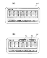
また、管理者コンピュータ95からクラウドサーバー93には、圃場情報が出力される。例えば、方形圃場A,B…における夫々の、四隅の経度・緯度情報、圃場面積、所在地情報…等である。図4(A)においては、圃場マスタとして例示する。なお、同図(B)は、営農集団等の所有する農業機械としてのトラクタのメーカと型式を表示する機械マスタである。   Further, the farm field information is output from the administrator computer 95 to the cloud server 93. For example, longitude / latitude information of four corners, field area, location information, etc. of each of the square fields A, B,. In FIG. 4A, it is illustrated as an agricultural field master. FIG. 2B is a machine master that displays the manufacturer and model of a tractor as an agricultural machine owned by a farming group or the like.

携帯端末92は、クラウドサーバー93のデータをダウンロード可能に設けられ、ダウンロードによって、作業計画1、作業計画2…毎に計画アイコン97、97…が作成され表示される構成である。 The portable terminal 92 is provided so that the data of the cloud server 93 can be downloaded, and a plan icon 97 1 , 97 2 ... Is created and displayed for each work plan 1, work plan 2.

そして、計画アイコン97をタップ操作すると、作業計画概要98が表示(図例では作業計画1に関する)され、この作業計画概要98の表示と共にタップ操作を受けて各詳細画面に移行するタップ選択表示部99を有する。すなわち、「詳細表示」「マップ」「作業開始」の表示に、タップ選択表示部99a,99b,99cを対応させている。このうち、「詳細表示」のタップ選択表示部99aをタップ操作すると、作業計画の詳細表示100(図例では作業計画1に関する)が実行される。なお、「詳細表示」には、圃場面積や作業者名など「概要表示」で省略された項目を表示できる(図5(A))。   When the plan icon 97 is tapped, a work plan summary 98 is displayed (related to work plan 1 in the example), and a tap selection display unit that receives the tap operation and moves to each detail screen together with the display of the work plan summary 98. 99. That is, the tap selection display portions 99a, 99b, and 99c are associated with “detailed display”, “map”, and “work start” display. Among these, when the tap selection display portion 99a of “detail display” is tapped, the work plan detail display 100 (related to the work plan 1 in the example) is executed. In the “detailed display”, items omitted in the “summary display” such as the field area and the operator name can be displayed (FIG. 5A).

タップ選択表示部99のうち、「作業開始」のタップ選択表示部99cを選択すると、トラクタは、所定の作業計画、例えば作業計画1に関する作業モードによって管理されることとなる。トラクタ側の情報管理端末91と携帯端末92との通信により、携帯端末92から作業計画の情報を送信し、情報管理端末91から携帯端末92にトラクタの各種情報を送信できる。なお、図6(A)(B)は情報管理端末91の液晶画面91Aへの表示一例を示す。図6(B)は、所定の営農集団全体の計画を示したり、当該農業機械としてのトラクタに関する表示に切り替える切替選択スイッチ91a,91bを備える。   When the “work start” tap selection display unit 99c is selected from the tap selection display unit 99, the tractor is managed by a work mode related to a predetermined work plan, for example, work plan 1. By communication between the information management terminal 91 on the tractor side and the portable terminal 92, work plan information can be transmitted from the portable terminal 92, and various information on the tractor can be transmitted from the information management terminal 91 to the portable terminal 92. 6A and 6B show examples of display on the liquid crystal screen 91A of the information management terminal 91. FIG. FIG. 6B includes changeover selection switches 91a and 91b that show a plan for the entire predetermined farming group or switch to a display relating to a tractor as the agricultural machine.

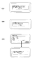
前記図5における作業計画1に基づき、指定以外である圃場Bにトラクタが入り、又は入ろうとすると、当初計画の圃場Aと異なるとして警報を発する。すなわち、携帯端末92には圃場進入適否判定手段Xを予め導入しておき、情報管理端末91からの情報に基づいて、圃場進入適否判定手段Xが作業計画1に指定する圃場とは異なる圃場と判定するときには、携帯端末92から情報管理端末91にブザー等の警報出力を出力する。情報管理端末91への警報出力は、トラクタに適宜配設するブザー等の警報手段を駆動する。同時に携帯端末92の画面には、ダイアログ表示101、すなわち「圃場Bの作業を実施しようとしています。作業計画1は圃場Aで行ってください。」と表示される(図7(A))。図8に示すように、圃場進入適否判定手段Xは、方形圃場における四隅の経度・緯度情報に基づいて予めこれら四隅に囲われるゾーンにトラクタが存在するか否かを判断する、あるいは、圃場の周辺所定距離に接近したときトラクタの進行方向延長線が上記ゾーンに干渉すべく接近しているかどうかを判断する、等である。方形圃場を応用し、圃場を類似多角形とみなして各点の経度緯度情報から圃場の形状やゾーンに相当するデータを演算することもできる。なお、トラクタの情報管理端末91にGPSアンテナを備え、現在位置を経度・緯度情報に変換して認識する手段を構成している(現在位置認識手段P)。   Based on the work plan 1 in FIG. 5, if a tractor enters or tries to enter the field B other than the designation, an alarm is issued as being different from the field A of the initial plan. That is, a field entry suitability determination unit X is previously introduced into the mobile terminal 92, and a field different from the field designated by the work plan 1 by the field entry suitability determination unit X based on the information from the information management terminal 91. When determining, an alarm output such as a buzzer is output from the portable terminal 92 to the information management terminal 91. The alarm output to the information management terminal 91 drives an alarm means such as a buzzer that is appropriately disposed on the tractor. At the same time, on the screen of the portable terminal 92, a dialog display 101 is displayed, that is, “Working on the field B is about to be performed. Work plan 1 should be performed on the field A” (FIG. 7A). As shown in FIG. 8, the agricultural field approach propriety determining means X determines whether or not a tractor exists in a zone surrounded by these four corners in advance based on the longitude / latitude information of the four corners in a square field, It is determined whether or not the extension line in the traveling direction of the tractor is approaching to interfere with the zone when approaching a predetermined peripheral distance. By applying a rectangular field, the field can be regarded as a similar polygon, and the data corresponding to the shape and zone of the field can be calculated from the longitude and latitude information of each point. The tractor information management terminal 91 is provided with a GPS antenna, and constitutes means for recognizing the current position by converting it into longitude / latitude information (current position recognition means P).

前記所定の作業計画の選択に基づいて、対応する作業モードでトラクタは管理されることとなるが、ここで作業計画で指定したトラクタなる農業機械あるいはトラクタの機種型式が、予め当該農業機械の情報管理端末91に記憶された農業機械の種類やトラクタの機種情報と比較され、取り扱う農業機械自体が当該記憶された農業機械と異なる場合、あるいは使用する農作業機が異なる場合、すなわち前記農機名や作業機名が情報管理端末91に記憶されたものと異なる場合、作業開始の条件入力とともに携帯端末92から情報管理端末91に選択機器相違による警報出力が実行され、当該農業機械に付設の警報ブザー等警報器が作動する(図9)(作業機器選択適否判定手段Y)。したがって、水田を適正重量のトラクタで耕耘する計画に対し、重量の大なるトラクタで実行してしまうと耕盤を踏み固める恐れがあるが、上記の構成をとることにより回避できる。   Based on the selection of the predetermined work plan, the tractor is managed in the corresponding work mode. Here, the agricultural machine or the model type of the tractor designated in the work plan is the information on the agricultural machine in advance. Compared with the type of agricultural machine stored in the management terminal 91 and the model information of the tractor, when the handled agricultural machine itself is different from the stored agricultural machine, or when the used agricultural machine is different, that is, the agricultural machine name and work When the machine name is different from the one stored in the information management terminal 91, the alarm output due to the difference in the selected device is executed from the portable terminal 92 to the information management terminal 91 together with the condition for starting the work, and the alarm buzzer attached to the agricultural machine, etc. The alarm is activated (FIG. 9) (working device selection suitability determining means Y). Therefore, when the paddy field is cultivated with a tractor having an appropriate weight, if the tractor with a heavy weight is used, there is a fear that the cultivator will be stepped on, but this can be avoided by adopting the above configuration.

作業計画による作業内容に対応できていないと判定される場合、例えば耕うんの作業内容でありながら、前記リフトアーム15の上昇角度を検出して耕耘作業に必要な作業機連結手段である3点リンクのロアリンク高さが高いままPTO駆動状態となっていると判断したり、ロアリンクが低いながらPTO非駆動の状態の場合には、携帯端末92は正常に耕耘運転が実行されていないと判断し、情報管理端末91に警報出力を出力するものである(図10)(作業内容選択適否判定手段Z)。   If it is determined that the work content according to the work plan cannot be dealt with, for example, the work content of tilling, the lift angle of the lift arm 15 is detected and the working machine connecting means necessary for the tilling work is detected. When the lower link height is high, it is determined that the PTO drive state is maintained, or when the lower link is low, but the PTO non-drive state is determined, the mobile terminal 92 is determined not to perform the tillage operation normally. Then, an alarm output is output to the information management terminal 91 (FIG. 10) (work content selection suitability determination means Z).

なお、作業内容異常の他の例として、コンバインの排藁落下に用いるドロッパ作業や排藁結束のノッタ作業を選択設定しているに関わらず、コンバインの情報管理端末から排藁を短く切断するカッタ作業の状態となっている場合がある。更に田植え機の場合、施肥作業を実行する作業計画に対し、これを行う機械状態でない場合である。   In addition, as another example of work content abnormality, a cutter that cuts the waste from the combine information management terminal shortly, regardless of whether the dropper work used to drop and drop the combine or the knot work of the waste binding is selected. There may be work status. Furthermore, in the case of a rice planting machine, it is a case where it is not the machine state which performs this with respect to the work plan which performs a fertilization work.

なお、これまでの説明では携帯端末92にダウンロードした作業計画等のデータとトラクタ等農業機械からの各種情報とを携帯端末92内で演算処理する形態としたが、クラウドサーバー93の作業計画等をトラクタ等農業機械の情報管理端末91に直接ダウンロードし農業機械自体の各種情報との組み合わせによって各種異常警報等を実行する形態としてもよい。ダイアログ表示の一例を前記図7(A)〜(C)に示す。なお、図7(C)は、作業内容選択適否判定手段Zの異なる例を示し、作業計画で立てた予定作業時刻と異なる時刻に作業計画に基づく作業を行う場合に表示される。   In the above description, the data such as the work plan downloaded to the mobile terminal 92 and various information from the agricultural machine such as the tractor are calculated in the mobile terminal 92. However, the work plan of the cloud server 93 is It is good also as a form which downloads directly to the information management terminal 91 of agricultural machines, such as a tractor, and performs various abnormality alarms etc. by the combination with the various information of agricultural machines itself. An example of the dialog display is shown in FIGS. FIG. 7C shows a different example of the work content selection suitability determination means Z, which is displayed when work based on the work plan is performed at a time different from the scheduled work time set in the work plan.

前記のように、圃場進入適否判定手段X、作業機器選択適否判定手段Y及び作業内容選択適否判定手段Zにより、農業機械の情報管理端末91の機械情報データと携帯端末92にダウンロードされた作業計画に基づく作業にそぐわない機械や条件であることが判定されると、その作業を中断しまたは警報出力によって作業回避の手段を講じるものであるから、無駄な作業の実行を回避できる。このように圃場進入適否判定手段X、作業機器選択適否判定手段Y及び作業内容選択適否判定手段Zによる適否判定は、所定の作業計画に対する作業適否判定手段Tを構成するものである。所定の作業計画に対する作業適否判定手段Tとしては、上記のほか、対象作物の品種の不一致判定、担当作業者の不一致判定等種々がある。   As described above, the work plan downloaded to the mobile terminal 92 and the machine information data of the information management terminal 91 of the agricultural machine by the field entry suitability judging means X, the work equipment selection suitability judging means Y, and the work content selection suitability judging means Z. If it is determined that the machine or the condition is not suitable for the work based on the above, the work is interrupted or a work avoidance means is provided by outputting an alarm, so that it is possible to avoid performing a useless work. Thus, the suitability determination by the farm entry suitability determination means X, the work equipment selection suitability determination means Y and the work content selection suitability determination means Z constitutes the work suitability determination means T for a predetermined work plan. In addition to the above, the work suitability determination means T for a predetermined work plan includes various types such as a mismatch determination of the varieties of the target crop, a mismatch determination of the worker in charge.

図11に基づき、クラウドサーバー93から直接農業機械であるトラクタの情報管理端末91に作業計画や圃場データをダウンロードする場合の他の農作業管理システム例について説明する。図11に示すように、所定のトラクタの液晶画面103に、「マスタ連携」「計画連携」「実績連携」「戻る」の各タップ選択表示部104a,104b,104c,104dを設けている。このうち、「計画連携」のタップ選択表示部104bを操作すると、液晶画面103に計画一覧105が表示される。この計画一覧105のうち、例えば「計画4」をタップ操作すると、計画概要106に表示移行する。さらに、この画面に同時に表示されるタップ選択表示部107のうち、「作業開始」のタップ選択表示部105cを操作する。この場合に、現在時刻と計画概要106の計画日時画面106aに表示の時刻との対比が実行される。現在時刻が未だ計画時刻に達していない場合には、警告のためにダイアログ画面108に移行し、実施予定時刻と当該現在時刻の実施計画内容を表示する(図8(C))。したがって、作業者はこの警告画面を確認することによって作業計画を正確に把握できる。   Based on FIG. 11, another example of a farm work management system in the case of downloading a work plan or field data from the cloud server 93 to the information management terminal 91 of the tractor that is an agricultural machine will be described. As shown in FIG. 11, tap selection display sections 104a, 104b, 104c, and 104d for “master cooperation”, “plan cooperation”, “result cooperation”, and “return” are provided on the liquid crystal screen 103 of a predetermined tractor. Among these, the plan list 105 is displayed on the liquid crystal screen 103 when the tap selection display unit 104 b for “plan cooperation” is operated. If, for example, “plan 4” is tapped in the plan list 105, the display shifts to the plan summary 106. Further, among the tap selection display units 107 displayed simultaneously on this screen, the “work start” tap selection display unit 105c is operated. In this case, the current time is compared with the time displayed on the plan date screen 106a of the plan summary 106. If the current time has not yet reached the planned time, the screen shifts to a dialog screen 108 for warning, and the scheduled execution time and the execution plan contents of the current time are displayed (FIG. 8C). Therefore, the worker can accurately grasp the work plan by confirming the warning screen.

前記計画一覧105には、「作業日時」と「作業状態完了」又は「作業未」の区別表示を可能に構成している。そして「作業日時」順に並べ替えることで、追加の作業計画の立案が容易になったり、作業完了の有無の確認も容易である。   The plan list 105 is configured to enable distinction between “work date and time” and “work status completed” or “no work”. By rearranging in the order of “work date”, it becomes easy to make an additional work plan, and it is easy to check whether the work has been completed.

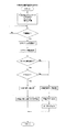
次いでクラウドサーバー93から前記情報管理端末91へダウンロードするタイミング等について説明する。図12において、トラクタのキースイッチのオン操作に基づいて作業計画のダウンロードが開始され(ステップ101,102)、ダウンロード終了する(ステップ103)。ところで前記ダウンロードが実行されて一定時間経過したか否か判断され(ステップ104)、一定時間経過するとステップ102に戻りダウンロードが実行される。ステップ104で一定時間経過しなくても計画変更の通知が入ると(ステップ105)、ステップ102に戻りダウンロードが実行される。   Next, timing for downloading from the cloud server 93 to the information management terminal 91 will be described. In FIG. 12, the download of the work plan is started based on the ON operation of the key switch of the tractor (steps 101 and 102), and the download is completed (step 103). By the way, it is determined whether or not a predetermined time has elapsed since the download was executed (step 104), and when the predetermined time has elapsed, the process returns to step 102 to execute the download. If a plan change notification is received in step 104 even if a predetermined time has not elapsed (step 105), the process returns to step 102 and download is executed.

計画変更の通知が入る毎にダウンロードすることにより、作業途中に作業者は、計画の変更や追加あるいは削除を都度把握できるものとなり、作業の効率を高める。   By downloading each time a plan change notification is received, the operator can grasp the change, addition or deletion of the plan every time during the work, thereby improving the work efficiency.

ここで、作業計画に基づき作業を実行する際に収集される作業データについて説明する。   Here, the work data collected when the work is executed based on the work plan will be described.

トラクタの場合、車両の基礎情報として車両管理情報、車両運転情報、作業機基礎運転情報があり、これらは前記情報管理端末91に情報収集される構成である。ここで情報管理端末91には前記GPSアンテナのほか、通信アンテナ又はモジュール、G(加速度)センサ、メモリー、電池などが配置されている。なお、前記車両管理情報の中には、例えば機種、型式、号機などの車両特定番号、車アワメータ情報である稼働時間、GPSが提供する位置情報が含まれ、前記車両運転情報の中には、例えばエンジンオイル圧力、エンジン冷却水温、瞬間燃費、燃料残量、3P位置情報、走行変速位置、車両車速情報、PTO回転数、エンジン回転数などがあり、前記作業機基礎運転情報の中には、例えば機種、型式、号機などの作業機特定番号、作業機がロータリ耕耘装置である場合の耕耘幅情報・耕深情報など、作業機が薬液散布装置である場合の農薬散布量(単位面積当たりの散布量)・農薬タンク残量・散布幅情報・収穫量情報などがある。   In the case of a tractor, vehicle basic information includes vehicle management information, vehicle driving information, and work machine basic driving information, which are collected by the information management terminal 91. Here, in addition to the GPS antenna, the information management terminal 91 includes a communication antenna or module, a G (acceleration) sensor, a memory, a battery, and the like. In addition, the vehicle management information includes, for example, a vehicle identification number such as a model, a model, and a car number, an operation time that is vehicle hour meter information, and position information provided by GPS. For example, there are engine oil pressure, engine coolant temperature, instantaneous fuel consumption, fuel remaining amount, 3P position information, travel shift position, vehicle vehicle speed information, PTO rotation speed, engine rotation speed, etc. For example, the work machine identification number (per unit area) when the work machine is a chemical spraying device, such as the work machine identification number, such as the model, model, unit, etc., and the cultivation width information and depth information when the work machine is a rotary tiller Application amount), remaining amount of agricultural chemical tank, application width information, yield information, etc.

そして、前記情報管理端末91は、上記トラクタから入手する情報を収集してデータの分析・加工を行い、当該情報としては、車両運転情報、稼働時間の収集、燃費の収集、故障情報などの車両情報、作業機毎の稼働情報、作業機消費財(例えば、使用する肥料など)情報、作業運転経路情報、作業機毎の車速情報などの農業機械特有情報がある。また前記データの分析・加工により、メンテナンス時期案内、燃費を節約するためのエコノミーな運転推奨案内など情報を提供することができる。前記メンテナンス時期案内は、故障修理の迅速対応、消耗部品時期案内などであり、前記燃費を節約するためのエコノミーな運転推奨案内は、圃場毎の土壌情報等の提供である。便宜上上記のデータ等を総称して機械稼動データと称する。   The information management terminal 91 collects information obtained from the tractor and analyzes and processes the data. The information includes vehicle operation information, operation time collection, fuel consumption collection, failure information, and other vehicles. There is information specific to agricultural machinery such as information, operation information for each work machine, work machine consumer goods (for example, fertilizer to be used) information, work operation route information, vehicle speed information for each work machine. Also, by analyzing and processing the data, it is possible to provide information such as maintenance timing guidance and economical driving recommendation guidance for saving fuel consumption. The maintenance time guidance is quick response to failure repair, consumable parts timing guidance, etc., and the economical driving recommendation guidance for saving fuel consumption is provision of soil information for each farm field. For convenience, the above data and the like are collectively referred to as machine operation data.

図13に本実施例のトラクタの車内LANシステムと、情報管理端末91及び外部装置としての携帯端末92のシステムの構成図を示す。   FIG. 13 shows a configuration diagram of a tractor in-vehicle LAN system, an information management terminal 91, and a portable terminal 92 as an external device according to the present embodiment.

即ち、トラクタの制御装置110にはエンジンECU111、作業機昇降系ECU112、走行系ECU113があり、互いにCAN2(Controller Area Network)で接続している。またトラクタは携帯端末92と情報管理端末91と外部通信ユニット114を備えており、情報管理端末91に対して近距離無線通信手段(例えばBlue tooth(登録商標))を介して携帯端末92に通信可能に構成している。また、情報管理端末91にはハードディスク115が接続している。携帯端末92は、タブレットPC、スマートフォン、パーソナルコンピュータなどが用いられ、後述の走行アシスト制御に関するプログラムを備え、画面による表示と共に当該制御を司る。   That is, the tractor control device 110 includes an engine ECU 111, a work implement elevating system ECU 112, and a traveling system ECU 113, which are connected to each other via a CAN 2 (Controller Area Network). The tractor includes a portable terminal 92, an information management terminal 91, and an external communication unit 114. The tractor communicates with the information management terminal 91 via the short-range wireless communication means (for example, Blue tooth (registered trademark)). It is configured as possible. A hard disk 115 is connected to the information management terminal 91. As the portable terminal 92, a tablet PC, a smartphone, a personal computer, or the like is used. The portable terminal 92 includes a program related to driving assist control, which will be described later, and manages the control along with display on the screen.

また、タッチパネル操作部を有する携帯端末92と前記情報通信端末90と外部通信ユニット114は互いにCAN1で接続している。またCAN1は作業機昇降系ECU112を介してトラクタ各制御系に接続され、更に外部接続カプラを介して作業機ECU116と接続しており、作業機ECU116Aは作業機がロータリ耕耘装置18の例を示し、ブーム伸縮位置、ブーム角度、薬液の液圧、液流量、液残量などの入力により液圧調整、ノズル切換え、ブーム伸縮、ブーム開閉などを行う電磁ソレノイドを作動できる構成になっている。なお、作業機を薬剤散布装置(図示せず)に交換すると、作業機ECU116Bへの接続となる。   Further, the portable terminal 92 having the touch panel operation unit, the information communication terminal 90, and the external communication unit 114 are connected to each other by CAN1. CAN1 is connected to each control system of the tractor via the work implement elevating system ECU 112, and further connected to the work implement ECU 116 via an external connection coupler. The work implement ECU 116A shows an example of the rotary tiller 18 as the work implement. The electromagnetic solenoid for adjusting the hydraulic pressure, switching the nozzle, extending and retracting the boom, opening and closing the boom, etc. can be operated by inputting the boom extension position, the boom angle, the chemical liquid pressure, the liquid flow rate, and the remaining liquid amount. When the work implement is replaced with a medicine spraying device (not shown), connection to the work implement ECU 116B is established.

次いで図14のフローチャートに基づき、作業データの蓄積を目的とした農作業管理システムにおける各種データの移行処理について説明する。   Next, based on the flowchart of FIG. 14, the migration process of various data in the farm work management system for the purpose of storing work data will be described.

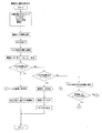
まず、トラクタ等農業機械側の情報管理端末91の機能・演算処理について、所定の作業を行うと、機械稼動データを収集し記憶する(ステップ201)。情報管理端末91が携帯端末92と接続中か否か判断し、接続中のときは当該機械稼動データを携帯端末92に送信する(ステップ202,ステップ203)。一方農業機械では判断できないところの圃場名や作業者名、あるいは作業内容、作物等のデータは携帯端末92からの送信を受けて記憶できる(ステップ204)。この受信データ、例えば肥料、農薬、資材、作業者名、作業内容、コメント、写真、動画等を対応する作業実績、例えば作業時刻と関連づけ、実績データとして記憶する(ステップ205)。情報管理端末91は、無線LANを介してクラウドサーバー93に実績データを送信し(ステップ206、ステップ207)、実績データの送信が完了すると(ステップ208)、キースイッチオフまで上記手順を繰り返す(ステップ209)。したがって、クラウドサーバー93に送信され保存された実績データはユーザ用コンピュータ94や管理者用コンピュータ95によって確認することができる。なお、ステップ206で実績データの送信はパソコン同士で通信できる形態としてもよい。   First, when a predetermined work is performed on the function / calculation processing of the information management terminal 91 on the agricultural machine side such as a tractor, machine operation data is collected and stored (step 201). It is determined whether or not the information management terminal 91 is connected to the portable terminal 92. When the information management terminal 91 is connected, the machine operation data is transmitted to the portable terminal 92 (step 202, step 203). On the other hand, data such as field names, worker names, work contents, crops, etc., which cannot be determined by the agricultural machine, can be stored by receiving transmission from the portable terminal 92 (step 204). The received data, for example, fertilizer, agrochemical, material, worker name, work content, comment, photograph, video, etc. are associated with the corresponding work performance, for example, work time, and stored as performance data (step 205). The information management terminal 91 transmits the result data to the cloud server 93 via the wireless LAN (step 206, step 207). When the result data transmission is completed (step 208), the above procedure is repeated until the key switch is turned off (step 208). 209). Therefore, the performance data transmitted to and stored in the cloud server 93 can be confirmed by the user computer 94 or the administrator computer 95. Note that the transmission of the result data in step 206 may be in a form in which the personal computers can communicate with each other.

一方、図 において、携帯端末92の機能・演算処理について、該携帯端末92がトラクタ等農業機械の情報管理端末91と接続中であると、農業機械の機械稼動データを受信して記憶する(ステップ301,ステップ302)。携帯端末92に、農業機械では判断できない情報やデータについては、手入力によるがこれらの入力があると(ステップ303)、入力データとして、例えば肥料、農薬、資材、作業者名、作業内容、コメント、写真、動画等は、対応する作業実績、例えば作業時刻と関連づけておく(ステップ304)。情報管理端末91と接続中であるか否かを判定し(ステップ305)、入力データをこの情報管理端末91に送信する(ステップ306)。図外アプリ終了ボタンがタップされるまで上記の手順を繰り返す(ステップ307)。   On the other hand, in the figure, regarding the function / calculation processing of the portable terminal 92, when the portable terminal 92 is connected to the information management terminal 91 of the agricultural machine such as a tractor, the machine operation data of the agricultural machine is received and stored (step 301, step 302). Information and data that cannot be determined by the agricultural machine in the portable terminal 92 are input manually (step 303). As input data, for example, fertilizer, agricultural chemicals, materials, worker names, work contents, comments, etc. , Photos, videos, and the like are associated with corresponding work performance, for example, work time (step 304). It is determined whether or not the information management terminal 91 is connected (step 305), and the input data is transmitted to the information management terminal 91 (step 306). The above procedure is repeated until the unillustrated application end button is tapped (step 307).

上記のように、農業機械の情報管理端末91と近距離通信可能な携帯端末92間でデータの授受を行い、結果として、情報管理端末91と携帯端末92とは同じデータを保有することとなる。したがって、例えば携帯端末92のみに作業データを集積させる形態では、携帯端末92を情報管理端末91に接続し忘れたり、携帯端末92の電池が切れるなどの理由によって作業データを取得できなくなる恐れがあるが、上記のように情報管理端末91側にも同一の作業データを蓄積でき、作業データの分析も正確になしえる。また、携帯端末92に直接手入力したデータも農業機械側情報管理端末91にデータ保有できるのでデータ漏れをなくする。さらに、この情報管理端末91からクラウドサーバー93等にデータを送信するものであるから携帯端末92での送信に比較してデータ漏れ等を生じ難い。   As described above, data is exchanged between the information management terminal 91 of the agricultural machine and the portable terminal 92 capable of near field communication. As a result, the information management terminal 91 and the portable terminal 92 have the same data. . Therefore, for example, in the form in which the work data is accumulated only in the mobile terminal 92, there is a possibility that the work data cannot be acquired due to forgetting to connect the mobile terminal 92 to the information management terminal 91 or the battery of the mobile terminal 92 is exhausted. However, the same work data can be stored on the information management terminal 91 side as described above, and the work data can be analyzed accurately. In addition, data manually input directly to the portable terminal 92 can be held in the agricultural machine side information management terminal 91, thereby eliminating data leakage. Furthermore, since data is transmitted from the information management terminal 91 to the cloud server 93 or the like, data leakage or the like is less likely to occur as compared with transmission by the portable terminal 92.

また、情報管理端末91からクラウドサーバー93への送信は、無線LAN接続等を経由して自動的に行える形態とするものであるから、作業者の負担を軽減できる。   In addition, since transmission from the information management terminal 91 to the cloud server 93 can be automatically performed via a wireless LAN connection or the like, the burden on the operator can be reduced.

91情報管理端末
92携帯端末
T作業適否判定手段
X圃場進入判定手段
Y作業機器選択適否判定手段
Z作業内容選択適否判定手段
91 information management terminal 92 portable terminal T work suitability judging means X field entry judging means Y work equipment selection suitability judging means Z work content selection suitability judging means

Claims (4)

農業機械に当該農業機械の各種作業データや農業機械の位置情報を取得する情報管理端末(91)を備え、この情報管理端末(91)と通信可能に設ける携帯端末(92)に、直接入力し又はネット回線等を経由することにより作業計画を導入する農作業管理システムにおいて、上記情報管理端末(91)に取得された農業機械に関するデータ、上記各種作業データおよび位置データにより農業機械による作業開始の際に所定の作業計画に対する作業適否を判断する作業適否判定手段(T)を構成し、作業適否判定手段(T)により不適と判断された場合に作業中断出力又は警報出力するよう構成した農作業管理システム。   The agricultural machine is provided with an information management terminal (91) that acquires various work data of the agricultural machine and position information of the agricultural machine, and is directly input to a portable terminal (92) provided to be communicable with the information management terminal (91). Or, in a farm work management system that introduces a work plan via a network or the like, when the work is started by the farm machine using the data on the farm machine acquired by the information management terminal (91), the various work data, and the position data. A farm work management system comprising work suitability judging means (T) for judging work suitability for a predetermined work plan and outputting work interruption or warning when it is judged unsuitable by the work suitability judging means (T) . 作業適否判定手段(T)は、農業機械が所定の作業計画の対象圃場であるか否かを判定する圃場進入判定手段(X)とした請求項1に記載の農作業管理システム。   The farm work management system according to claim 1, wherein the work propriety judging means (T) is field entry judging means (X) for judging whether or not the agricultural machine is a target field for a predetermined work plan. 作業適否判定手段(T)は、作業機器選択適否判定手段(Y)とした請求項1に記載の農作業管理システム。   The farm work management system according to claim 1, wherein the work suitability determination means (T) is a work equipment selection suitability determination means (Y). 作業適否判定手段(T)は、作業内容選択適否判定手段(Z)とした請求項1に記載の農作業管理システム。   The farm work management system according to claim 1, wherein the work suitability determination means (T) is a work content selection suitability determination means (Z).
JP2016015933A 2016-01-29 2016-01-29 Farm work management system Pending JP2017134747A (en)

Priority Applications (1)

Application Number Priority Date Filing Date Title
JP2016015933A JP2017134747A (en) 2016-01-29 2016-01-29 Farm work management system

Applications Claiming Priority (1)

Application Number Priority Date Filing Date Title
JP2016015933A JP2017134747A (en) 2016-01-29 2016-01-29 Farm work management system

Publications (1)

Publication Number Publication Date
JP2017134747A true JP2017134747A (en) 2017-08-03

Family

ID=59502875

Family Applications (1)

Application Number Title Priority Date Filing Date
JP2016015933A Pending JP2017134747A (en) 2016-01-29 2016-01-29 Farm work management system

Country Status (1)

Country Link
JP (1) JP2017134747A (en)

Cited By (5)

* Cited by examiner, † Cited by third party
Publication number Priority date Publication date Assignee Title
CN107318495A (en) * 2017-08-15 2017-11-07 湖北科技学院 A kind of multiple common management systems of three-dimensional agriculture planting shed based on Internet of Things
JP2019101759A (en) * 2017-12-01 2019-06-24 井関農機株式会社 Farm work information management system
WO2019142467A1 (en) * 2018-01-22 2019-07-25 株式会社クボタ Agriculture support system
JP2020154783A (en) * 2019-03-20 2020-09-24 ヤンマーパワーテクノロジー株式会社 Work machine and work machine management system
JP2020194276A (en) * 2019-05-27 2020-12-03 ヤンマーパワーテクノロジー株式会社 Work information providing device and work information providing system

Cited By (11)

* Cited by examiner, † Cited by third party
Publication number Priority date Publication date Assignee Title
CN107318495A (en) * 2017-08-15 2017-11-07 湖北科技学院 A kind of multiple common management systems of three-dimensional agriculture planting shed based on Internet of Things
JP2019101759A (en) * 2017-12-01 2019-06-24 井関農機株式会社 Farm work information management system
WO2019142467A1 (en) * 2018-01-22 2019-07-25 株式会社クボタ Agriculture support system
JP2019128660A (en) * 2018-01-22 2019-08-01 株式会社クボタ Agriculture support system
CN111095340A (en) * 2018-01-22 2020-05-01 株式会社久保田 Agricultural auxiliary system
EP3751501A4 (en) * 2018-01-22 2021-10-13 Kubota Corporation Agriculture support system
JP7009229B2 (en) 2018-01-22 2022-01-25 株式会社クボタ Agricultural support system
JP2020154783A (en) * 2019-03-20 2020-09-24 ヤンマーパワーテクノロジー株式会社 Work machine and work machine management system
JP7220103B2 (en) 2019-03-20 2023-02-09 ヤンマーパワーテクノロジー株式会社 Work equipment and work equipment management system
JP2020194276A (en) * 2019-05-27 2020-12-03 ヤンマーパワーテクノロジー株式会社 Work information providing device and work information providing system
JP7316840B2 (en) 2019-05-27 2023-07-28 ヤンマーパワーテクノロジー株式会社 Work information providing device and work information providing system

Similar Documents

Publication Publication Date Title
JP2017134747A (en) Farm work management system
JP6467897B2 (en) Tractor
JP5919799B2 (en) LAN system for work vehicles
JP2015112056A (en) Agricultural work vehicle
US20140224888A1 (en) Identification code based information system
EP3173277B1 (en) Work vehicle
DE102008053907A1 (en) Work tool notification and user-selectable machine control configuration
US20140240506A1 (en) Display System Layout for Remote Monitoring of Machines
US20160232814A1 (en) Training Apparatus
JP2018033344A (en) Farm work machine
JP2014192740A (en) Work vehicle operation system and work vehicle operation program
JP2020005595A (en) Work vehicle
EP3417697B1 (en) Forming machine, grass management system, and method for operating
JP6695696B2 (en) Display device
US20190375294A1 (en) Working machine
US20190373806A1 (en) Working machine and display device for the same
JP6717366B2 (en) Tractor
US20220410987A1 (en) Work machine
JP2017029034A (en) Agricultural working vehicle
US20210394785A1 (en) Remote manual and autonomous work machine control
JP6879183B2 (en) Agricultural work information management system
JP2005080550A (en) Control system for working implement
JP7275072B2 (en) Work vehicle and work vehicle support system
US11497160B2 (en) Working machine
JP7293107B2 (en) Working vehicle and information display system for working vehicle