JP2017133594A - Fluid pump unit - Google Patents
Fluid pump unit Download PDFInfo
- Publication number
- JP2017133594A JP2017133594A JP2016013920A JP2016013920A JP2017133594A JP 2017133594 A JP2017133594 A JP 2017133594A JP 2016013920 A JP2016013920 A JP 2016013920A JP 2016013920 A JP2016013920 A JP 2016013920A JP 2017133594 A JP2017133594 A JP 2017133594A
- Authority
- JP
- Japan
- Prior art keywords
- oil
- oil passage
- pump unit
- electric pump
- distribution member
- Prior art date
- Legal status (The legal status is an assumption and is not a legal conclusion. Google has not performed a legal analysis and makes no representation as to the accuracy of the status listed.)
- Pending
Links
- 239000012530 fluid Substances 0.000 title claims abstract description 54
- 238000001816 cooling Methods 0.000 claims abstract description 43
- 238000001514 detection method Methods 0.000 claims description 8
- 239000003921 oil Substances 0.000 description 307
- 239000010687 lubricating oil Substances 0.000 description 9
- 230000005540 biological transmission Effects 0.000 description 6
- 238000012986 modification Methods 0.000 description 3
- 230000004048 modification Effects 0.000 description 3
- 230000000694 effects Effects 0.000 description 2
- XAGFODPZIPBFFR-UHFFFAOYSA-N aluminium Chemical compound [Al] XAGFODPZIPBFFR-UHFFFAOYSA-N 0.000 description 1
- 229910052782 aluminium Inorganic materials 0.000 description 1
- 239000010724 circulating oil Substances 0.000 description 1
- 238000010586 diagram Methods 0.000 description 1
- 239000000945 filler Substances 0.000 description 1
- 239000000446 fuel Substances 0.000 description 1
- 238000009434 installation Methods 0.000 description 1
- 239000007788 liquid Substances 0.000 description 1
- 230000001050 lubricating effect Effects 0.000 description 1
- 238000005461 lubrication Methods 0.000 description 1
- 238000012856 packing Methods 0.000 description 1
- 238000007789 sealing Methods 0.000 description 1
- XLYOFNOQVPJJNP-UHFFFAOYSA-N water Substances O XLYOFNOQVPJJNP-UHFFFAOYSA-N 0.000 description 1
Images


Classifications
-
- F—MECHANICAL ENGINEERING; LIGHTING; HEATING; WEAPONS; BLASTING
- F16—ENGINEERING ELEMENTS AND UNITS; GENERAL MEASURES FOR PRODUCING AND MAINTAINING EFFECTIVE FUNCTIONING OF MACHINES OR INSTALLATIONS; THERMAL INSULATION IN GENERAL
- F16H—GEARING
- F16H57/00—General details of gearing
- F16H57/04—Features relating to lubrication or cooling or heating
- F16H57/0412—Cooling or heating; Control of temperature
- F16H57/0413—Controlled cooling or heating of lubricant; Temperature control therefor
-
- F—MECHANICAL ENGINEERING; LIGHTING; HEATING; WEAPONS; BLASTING
- F16—ENGINEERING ELEMENTS AND UNITS; GENERAL MEASURES FOR PRODUCING AND MAINTAINING EFFECTIVE FUNCTIONING OF MACHINES OR INSTALLATIONS; THERMAL INSULATION IN GENERAL
- F16H—GEARING
- F16H57/00—General details of gearing
- F16H57/04—Features relating to lubrication or cooling or heating
- F16H57/0412—Cooling or heating; Control of temperature
- F16H57/0415—Air cooling or ventilation; Heat exchangers; Thermal insulations
-
- F—MECHANICAL ENGINEERING; LIGHTING; HEATING; WEAPONS; BLASTING
- F04—POSITIVE - DISPLACEMENT MACHINES FOR LIQUIDS; PUMPS FOR LIQUIDS OR ELASTIC FLUIDS
- F04B—POSITIVE-DISPLACEMENT MACHINES FOR LIQUIDS; PUMPS
- F04B17/00—Pumps characterised by combination with, or adaptation to, specific driving engines or motors
- F04B17/03—Pumps characterised by combination with, or adaptation to, specific driving engines or motors driven by electric motors
-
- F—MECHANICAL ENGINEERING; LIGHTING; HEATING; WEAPONS; BLASTING
- F04—POSITIVE - DISPLACEMENT MACHINES FOR LIQUIDS; PUMPS FOR LIQUIDS OR ELASTIC FLUIDS
- F04B—POSITIVE-DISPLACEMENT MACHINES FOR LIQUIDS; PUMPS
- F04B53/00—Component parts, details or accessories not provided for in, or of interest apart from, groups F04B1/00 - F04B23/00 or F04B39/00 - F04B47/00
- F04B53/22—Arrangements for enabling ready assembly or disassembly
-
- F—MECHANICAL ENGINEERING; LIGHTING; HEATING; WEAPONS; BLASTING
- F16—ENGINEERING ELEMENTS AND UNITS; GENERAL MEASURES FOR PRODUCING AND MAINTAINING EFFECTIVE FUNCTIONING OF MACHINES OR INSTALLATIONS; THERMAL INSULATION IN GENERAL
- F16H—GEARING
- F16H57/00—General details of gearing
- F16H57/04—Features relating to lubrication or cooling or heating
- F16H57/0405—Monitoring quality of lubricant or hydraulic fluids
-
- F—MECHANICAL ENGINEERING; LIGHTING; HEATING; WEAPONS; BLASTING
- F16—ENGINEERING ELEMENTS AND UNITS; GENERAL MEASURES FOR PRODUCING AND MAINTAINING EFFECTIVE FUNCTIONING OF MACHINES OR INSTALLATIONS; THERMAL INSULATION IN GENERAL
- F16H—GEARING
- F16H57/00—General details of gearing
- F16H57/04—Features relating to lubrication or cooling or heating
- F16H57/042—Guidance of lubricant
- F16H57/0421—Guidance of lubricant on or within the casing, e.g. shields or baffles for collecting lubricant, tubes, pipes, grooves, channels or the like
- F16H57/0423—Lubricant guiding means mounted or supported on the casing, e.g. shields or baffles for collecting lubricant, tubes or pipes
-
- F—MECHANICAL ENGINEERING; LIGHTING; HEATING; WEAPONS; BLASTING
- F16—ENGINEERING ELEMENTS AND UNITS; GENERAL MEASURES FOR PRODUCING AND MAINTAINING EFFECTIVE FUNCTIONING OF MACHINES OR INSTALLATIONS; THERMAL INSULATION IN GENERAL
- F16H—GEARING
- F16H57/00—General details of gearing
- F16H57/04—Features relating to lubrication or cooling or heating
- F16H57/042—Guidance of lubricant
- F16H57/0421—Guidance of lubricant on or within the casing, e.g. shields or baffles for collecting lubricant, tubes, pipes, grooves, channels or the like
- F16H57/0424—Lubricant guiding means in the wall of or integrated with the casing, e.g. grooves, channels, holes
-
- F—MECHANICAL ENGINEERING; LIGHTING; HEATING; WEAPONS; BLASTING
- F16—ENGINEERING ELEMENTS AND UNITS; GENERAL MEASURES FOR PRODUCING AND MAINTAINING EFFECTIVE FUNCTIONING OF MACHINES OR INSTALLATIONS; THERMAL INSULATION IN GENERAL
- F16H—GEARING
- F16H57/00—General details of gearing
- F16H57/04—Features relating to lubrication or cooling or heating
- F16H57/0434—Features relating to lubrication or cooling or heating relating to lubrication supply, e.g. pumps ; Pressure control
- F16H57/0435—Pressure control for supplying lubricant; Circuits or valves therefor
-
- F—MECHANICAL ENGINEERING; LIGHTING; HEATING; WEAPONS; BLASTING
- F16—ENGINEERING ELEMENTS AND UNITS; GENERAL MEASURES FOR PRODUCING AND MAINTAINING EFFECTIVE FUNCTIONING OF MACHINES OR INSTALLATIONS; THERMAL INSULATION IN GENERAL
- F16H—GEARING
- F16H57/00—General details of gearing
- F16H57/04—Features relating to lubrication or cooling or heating
- F16H57/0434—Features relating to lubrication or cooling or heating relating to lubrication supply, e.g. pumps ; Pressure control
- F16H57/0436—Pumps
-
- F—MECHANICAL ENGINEERING; LIGHTING; HEATING; WEAPONS; BLASTING
- F16—ENGINEERING ELEMENTS AND UNITS; GENERAL MEASURES FOR PRODUCING AND MAINTAINING EFFECTIVE FUNCTIONING OF MACHINES OR INSTALLATIONS; THERMAL INSULATION IN GENERAL
- F16H—GEARING
- F16H57/00—General details of gearing
- F16H57/04—Features relating to lubrication or cooling or heating
- F16H57/0434—Features relating to lubrication or cooling or heating relating to lubrication supply, e.g. pumps ; Pressure control
- F16H57/0441—Arrangements of pumps
-
- F—MECHANICAL ENGINEERING; LIGHTING; HEATING; WEAPONS; BLASTING
- F16—ENGINEERING ELEMENTS AND UNITS; GENERAL MEASURES FOR PRODUCING AND MAINTAINING EFFECTIVE FUNCTIONING OF MACHINES OR INSTALLATIONS; THERMAL INSULATION IN GENERAL
- F16H—GEARING
- F16H57/00—General details of gearing
- F16H57/04—Features relating to lubrication or cooling or heating
- F16H57/048—Type of gearings to be lubricated, cooled or heated
- F16H57/0482—Gearings with gears having orbital motion
-
- F—MECHANICAL ENGINEERING; LIGHTING; HEATING; WEAPONS; BLASTING
- F16—ENGINEERING ELEMENTS AND UNITS; GENERAL MEASURES FOR PRODUCING AND MAINTAINING EFFECTIVE FUNCTIONING OF MACHINES OR INSTALLATIONS; THERMAL INSULATION IN GENERAL
- F16H—GEARING
- F16H57/00—General details of gearing
- F16H57/02—Gearboxes; Mounting gearing therein
- F16H2057/02026—Connection of auxiliaries with a gear case; Mounting of auxiliaries on the gearbox
Landscapes
- Engineering & Computer Science (AREA)
- General Engineering & Computer Science (AREA)
- Mechanical Engineering (AREA)
- Quality & Reliability (AREA)
- General Details Of Gearings (AREA)
- Details Of Reciprocating Pumps (AREA)
Abstract
Description
本発明は、流体ポンプユニットに関し、特に、電動ポンプ部と冷却部とを備えた流体ポンプユニットに関する。 The present invention relates to a fluid pump unit, and more particularly, to a fluid pump unit including an electric pump unit and a cooling unit.
従来、電動ポンプ部と冷却部とを備えた流体ポンプユニットが知られている(たとえば、特許文献1参照)。 Conventionally, a fluid pump unit including an electric pump unit and a cooling unit is known (see, for example, Patent Document 1).
上記特許文献1には、油圧ポンプと冷却器とを備える回転式冷却器付き変速機が開示されている。この回転式冷却器付き変速機では、変速機の入力軸に回転式冷却器が取り付けられている。また、回転式冷却器付き変速機には、油溜部を有する歯車箱が設けられている。そして、油溜部に貯留された潤滑油が油圧ポンプにより吸い上げられて、歯車箱に設けられた軸受箱の入口流路に吐出される。歯車箱の入口流路に吐出された潤滑油は、回転式冷却器に流入して冷却される。冷却された潤滑油は、軸受箱の出口流路から排出される。出口流路から排出された潤滑油は、軸受箱の給油口に導入されて、潤滑箇所に供給される。 Patent Document 1 discloses a transmission with a rotary cooler including a hydraulic pump and a cooler. In this transmission with a rotary cooler, the rotary cooler is attached to the input shaft of the transmission. Further, the transmission with the rotary cooler is provided with a gear box having an oil reservoir. The lubricating oil stored in the oil reservoir is sucked up by the hydraulic pump and discharged to the inlet flow path of the bearing box provided in the gear box. The lubricating oil discharged to the inlet passage of the gear box flows into the rotary cooler and is cooled. The cooled lubricating oil is discharged from the outlet passage of the bearing box. The lubricating oil discharged from the outlet channel is introduced into the oil supply port of the bearing box and supplied to the lubricating portion.
上記特許文献1の回転式冷却器付き変速機(流体ポンプユニット)では、油圧ポンプと油圧ポンプから流出した潤滑油が導入される入口流路との間(回転式冷却器により冷却された潤滑油が流出する出口流路と給油口との間)の接続は明記されていないが、一般的には、配管を介して接続されると考えられる。しかしながら、油圧ポンプおよび入口流路(給油口(回転式冷却器および給油口)を配管を介して接続した場合には、配管が回転式冷却器付き変速機の外側に飛び出すように配置されるため、その分、流体ポンプユニットが大型化するという問題点がある。 In the transmission with a rotary cooler (fluid pump unit) of Patent Document 1 above, between the hydraulic pump and the inlet channel into which the lubricating oil flowing out from the hydraulic pump is introduced (the lubricating oil cooled by the rotary cooler). The connection between the outlet channel from which the gas flows out and the fuel filler port is not specified, but it is generally considered that the connection is made through piping. However, when the hydraulic pump and the inlet channel (oil supply port (rotary cooler and oil supply port) are connected via a pipe, the pipe is arranged so as to jump out of the transmission with the rotary cooler. Therefore, there is a problem that the fluid pump unit is increased in size.
この発明は、上記のような課題を解決するためになされたものであり、この発明の1つの目的は、大型化するのを抑制することが可能な流体ポンプユニットを提供することである。 The present invention has been made to solve the above-described problems, and an object of the present invention is to provide a fluid pump unit capable of suppressing an increase in size.
上記目的を達成するために、この発明の一の局面における流体ポンプユニットは、ギヤ機構内に流体を循環させるための電動ポンプ部と、循環される流体を冷却するための冷却部と、ギヤ機構に配置されるとともに、電動ポンプ部と冷却部とが設けられ、電動ポンプ部に接続される第1流路と、冷却部に接続される第2流路とを内部に含む流路分配部材とを備える。 In order to achieve the above object, a fluid pump unit according to one aspect of the present invention includes an electric pump unit for circulating a fluid in a gear mechanism, a cooling unit for cooling the circulating fluid, and a gear mechanism. And a flow distribution member that includes an electric pump unit and a cooling unit, and includes a first flow channel connected to the electric pump unit and a second flow channel connected to the cooling unit. Is provided.
この発明の一の局面による流体ポンプユニットでは、上記のように、電動ポンプ部と冷却部とが設けられ、電動ポンプ部に接続される第1流路と、冷却部に接続される第2流路とを内部に含む流路分配部材を備える。これにより、電動ポンプ部に接続される第1流路と冷却部に接続される第2流路とが流路分配部材の内部に配置されるので、電動ポンプ部や冷却部に接続される流路を流体ポンプユニットの外側に飛び出すように配置される配管により構成する場合と異なり、流体ポンプユニットが大型化するのを抑制することができる。 In the fluid pump unit according to one aspect of the present invention, as described above, the electric pump unit and the cooling unit are provided, the first flow path connected to the electric pump unit, and the second flow connected to the cooling unit. And a flow path distribution member including a path therein. As a result, the first flow path connected to the electric pump section and the second flow path connected to the cooling section are arranged inside the flow path distribution member, so that the flow connected to the electric pump section and the cooling section is set. Unlike the case where the path is constituted by piping arranged so as to jump out of the fluid pump unit, the fluid pump unit can be prevented from being enlarged.
また、電動ポンプ部に接続される第1流路と冷却部に接続される第2流路とが流路分配部材の内部に配置されるので、第1流路と第2流路とを流路分配部材内に集中して(近接して)配置することができる。これにより、第1流路と第2流路とを別個の部材(配管など)により構成する場合と異なり、部品点数の増加および構成の複雑化を抑制することができるとともに、流体ポンプユニットが大型化するのをより抑制することができる。 In addition, since the first flow path connected to the electric pump section and the second flow path connected to the cooling section are disposed inside the flow path distribution member, the first flow path and the second flow path are flown through. They can be concentrated (close to) in the path distribution member. Thus, unlike the case where the first flow path and the second flow path are configured by separate members (such as pipes), an increase in the number of parts and complication of the configuration can be suppressed, and the fluid pump unit is large-sized. Can be further suppressed.
また、電動ポンプ部と冷却部とが流路分配部材に設けられているので、電動ポンプ部、冷却部および流路分配部材を一体化した状態でギヤ機構に取り付けることができる。これにより、電動ポンプ部と冷却部とを個別にギヤ機構に取り付けた後に、電動ポンプ部、冷却部およびギヤ機構をそれぞれ配管により接続する場合と異なり、電動ポンプ部および冷却部の取り付け作業を簡略化することができる。また、電動ポンプ部および冷却部を直接ギヤ機構に取り付ける場合と異なり、ギヤ機構に電動ポンプ部および冷却部を取り付けるためのスペースを設ける必要がない。 In addition, since the electric pump unit and the cooling unit are provided in the flow channel distribution member, the electric pump unit, the cooling unit, and the flow channel distribution member can be attached to the gear mechanism in an integrated state. Unlike the case where the electric pump unit, the cooling unit and the gear mechanism are connected by piping after the electric pump unit and the cooling unit are individually attached to the gear mechanism, the mounting work of the electric pump unit and the cooling unit is simplified. Can be Further, unlike the case where the electric pump unit and the cooling unit are directly attached to the gear mechanism, it is not necessary to provide a space for attaching the electric pump unit and the cooling unit to the gear mechanism.
上記一の局面による流体ポンプユニットにおいて、好ましくは、第1流路には、電動ポンプ部の吐出口と吸入口とが液密的に接続され、第2流路には、冷却部の排出口と導入口とが液密的に接続されている。 In the fluid pump unit according to the above aspect, preferably, the discharge port and the suction port of the electric pump unit are liquid-tightly connected to the first channel, and the discharge port of the cooling unit is connected to the second channel. And the inlet are liquid-tightly connected.
このように構成すれば、第1流路と電動ポンプ部の吐出口および吸入口とを(第2流路と冷却部の排出口および導入口とを)配管を介して接続する場合と異なり、流体ポンプユニットが大型化するのをさらに抑制することができる。 If comprised in this way, unlike the case where the 1st flow path and the discharge port and suction port of an electric pump part are connected via piping (the 2nd flow path and the discharge port and introduction port of a cooling unit), An increase in size of the fluid pump unit can be further suppressed.
上記一の局面による流体ポンプユニットにおいて、好ましくは、流路分配部材は、板形状を有し、板形状の流路分配部材の第1の面に冷却部が設けられるとともに、第1の面とは異なる第2の面に電動ポンプ部が設けられている。 In the fluid pump unit according to the above aspect, preferably, the flow path distribution member has a plate shape, the cooling surface is provided on the first surface of the plate-shaped flow path distribution member, and the first surface; An electric pump portion is provided on a different second surface.
このように構成すれば、冷却部と電動ポンプ部とが異なる面に配置されるので、冷却部と電動ポンプ部とを同一の面に並列するように配置する場合と比べて、板形状の流路分配部材を構成する1つの面の大きさ(すなわち、板形状の流路分配部材の大きさ)を小さくすることができる。その結果、流路分配部材内に設けられる第1流路および第2流路の長さが長くなることを抑制することができる。 With this configuration, since the cooling unit and the electric pump unit are arranged on different surfaces, the plate-shaped flow is different from the case where the cooling unit and the electric pump unit are arranged in parallel on the same surface. The size of one surface constituting the channel distribution member (that is, the size of the plate-shaped channel distribution member) can be reduced. As a result, it is possible to suppress an increase in the length of the first flow path and the second flow path provided in the flow path distribution member.
この場合、好ましくは、第1の面は、流路分配部材のギヤ機構に配置される側とは反対側の面であり、第2の面は、第1の面に直交する流路分配部の側面である。 In this case, it is preferable that the first surface is a surface opposite to the side disposed on the gear mechanism of the flow channel distribution member, and the second surface is a flow channel distribution unit orthogonal to the first surface. Of the side.
このように構成すれば、電動ポンプ部からの流体の吐出方向(吸入方向)と、冷却部からの流体の排出方向(導入方向)とを直交させることができるので、電動ポンプ部と冷却部とを接続する流路を直交する直線状の流路により構成することができる。これにより、電動ポンプ部と冷却部とを接続する流路が湾曲している場合と異なり、流路の長さが長くなるのを抑制することができる。 If comprised in this way, since the discharge direction (suction direction) of the fluid from an electric pump part and the discharge direction (introduction direction) of the fluid from a cooling part can be orthogonally crossed, an electric pump part and a cooling part The flow path connecting the two can be constituted by a linear flow path orthogonal to each other. Thereby, unlike the case where the flow path which connects an electric pump part and a cooling part is curving, it can control that the length of a flow path becomes long.
上記一の局面による流体ポンプユニットにおいて、好ましくは、第2流路に設けられ、流体の流量を調整するためのオリフィスをさらに備える。 The fluid pump unit according to the above aspect preferably further includes an orifice provided in the second flow path for adjusting the flow rate of the fluid.
このように構成すれば、オリフィスが流路分配部材内の第2流路に取り付けられるので、電動ポンプ部、冷却部および流路分配部材に加えて、オリフィスも一体化した状態でギヤ機構に取り付けることができる。また、オリフィスにより流体の流量(液量)を調整することができるので、電動ポンプ部の容量を適切に設定する(小さくする)ことができる。すなわち、電動ポンプ部の容量が過度に大きく設定されるのを抑制することができる。 If comprised in this way, since an orifice is attached to the 2nd flow path in a flow-path distribution member, in addition to an electric pump part, a cooling part, and a flow-path distribution member, it attaches to a gear mechanism in the state which integrated the orifice. be able to. Moreover, since the flow rate (fluid amount) of the fluid can be adjusted by the orifice, the capacity of the electric pump unit can be appropriately set (reduced). That is, it is possible to suppress the capacity of the electric pump unit from being set excessively large.
上記一の局面による流体ポンプユニットにおいて、好ましくは、流路分配部材に設けられ、流体の状態を検知する検知部をさらに備える。 In the fluid pump unit according to the above aspect, it is preferable that the fluid pump unit further includes a detection unit that is provided in the flow path distribution member and detects the state of the fluid.
このように構成すれば、検知部が流路分配部材内に取り付けられるので、電動ポンプ部、冷却部および流路分配部材に加えて、検知部も一体化した状態でギヤ機構に取り付けることができる。また、検知部により検知された流体の状態に基づいて、電動ポンプ部の運転を最適化することができる。 If comprised in this way, since a detection part is attached in a flow-path distribution member, in addition to an electric pump part, a cooling part, and a flow-path distribution member, a detection part can also be attached to a gear mechanism in the integrated state. . Further, the operation of the electric pump unit can be optimized based on the state of the fluid detected by the detection unit.
なお、上記一の局面による流体ポンプユニットにおいて、以下の構成も考えられる。 In the fluid pump unit according to the above aspect, the following configuration is also conceivable.
(付記項1)
すなわち、上記一の局面による流体ポンプユニットにおいて、第2流路は、冷却部から排出された流体を分岐して、ギヤ機構に導入するように構成されている。
(Additional item 1)
That is, in the fluid pump unit according to the first aspect, the second flow path is configured to branch the fluid discharged from the cooling unit and introduce the fluid into the gear mechanism.
(付記項2)
また、上記一の局面による流体ポンプユニットにおいて、検知部は、流体温度センサおよび流体圧力センサのうちの少なくとも1つを含む。
(Appendix 2)
In the fluid pump unit according to the above aspect, the detection unit includes at least one of a fluid temperature sensor and a fluid pressure sensor.
(付記項3)
また、上記一の局面による流体ポンプユニットにおいて、第1流路および第2流路は、それぞれ、直交する複数の直線状の流路により構成されている。
(Additional Item 3)
In the fluid pump unit according to the aforementioned aspect, each of the first flow path and the second flow path is configured by a plurality of orthogonal straight flow paths.
以下、本発明の実施形態を図面に基づいて説明する。 Hereinafter, embodiments of the present invention will be described with reference to the drawings.
図1〜図11を参照して、本発明の一実施形態によるオイルポンプユニット100(流体ポンプユニットの一例)について説明する。なお、この明細書において「直交」とは、90度の角度で交差することに加えて、略90度の角度で交差することを含む広い概念である。 With reference to FIGS. 1-11, the oil pump unit 100 (an example of a fluid pump unit) by one Embodiment of this invention is demonstrated. In this specification, “orthogonal” is a broad concept including intersecting at an angle of approximately 90 degrees in addition to intersecting at an angle of 90 degrees.
(ギヤ機構の概略構成)
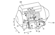
オイルポンプユニット100は、図1、図2、図4および図7に示すように、ギヤ機構200に取り付けられている。図1に示すように、ギヤ機構200は、ディファレンシャルギヤ201を備えている。ディファレンシャルギヤ201には、シャフト202が接続されている。シャフト202は、複数の軸受け203によって支持されている。また、シャフト202には、ギヤ204およびモータジェネレータ205が接続されている。また、シャフト202の一方端と他方端とには、オイルシール206を介して車両の車輪207が接続されている。また、ギヤ機構200は、シャフト202に平行に配置されたシャフト208を備えている。シャフト208は、複数の軸受け209によって支持されている。また、シャフト208には、ギヤ210が接続されている。
(Schematic configuration of gear mechanism)
The
(オイルポンプユニットの構成)
図1に示すように、オイルポンプユニット100は、ギヤ機構200内に油(流体の一例)を循環させるための電動ポンプ部10を備えている。電動ポンプ部10は、吐出口11と吸入口12とを有する。また、オイルポンプユニット100は、循環される油を冷却するためのオイルクーラ20(冷却部の一例)を備えている。オイルクーラ20は、排出口21と導入口22とを有する。
(Configuration of oil pump unit)
As shown in FIG. 1, the
ここで、本実施形態では、オイルポンプユニット100は、油路分配部材30(流路分配部材の一例)を備えている。油路分配部材30は、ギヤ機構200に配置されている。具体的には、油路分配部材30は、ギヤ機構200に直接取り付けられている。また、油路分配部材30には、電動ポンプ部10とオイルクーラ20とが設けられている。そして、油路分配部材30は、電動ポンプ部10に接続される油路31(第1油路の一例)を内部に含んでいる。また、油路分配部材30は、オイルクーラ20に接続される油路32(第2流路の一例)を内部に含んでいる。なお、油路分配部材30は、アルミニウムなどから構成されている。また、油路31および油路32は、ドリルなどにより油路分配部材30を加工する(孔を開ける)ことにより、形成されている。
Here, in the present embodiment, the
具体的には、油路31は、ギヤ機構200と電動ポンプ部10の吸入口12とを接続する油路31aを有する。また、油路31は、電動ポンプ部10の吐出口11に接続される油路31bを有する。油路32は、オイルクーラ20の吸入口12に接続される油路32aを有する。また、油路32は、オイルクーラ20の排出口21に接続される油路32bを有する。なお、電動ポンプ部10の吐出口11に接続される油路31bと、オイルクーラ20の吸入口12に接続される油路32aとは、接続されている(1つの油路を形成している)。
Specifically, the
また、油路32(油路32b)は、オイルクーラ20から排出された油を分岐して、ギヤ機構200に導入するように構成されている。具体的には、油路32(油路32b)は、油路32bから3つに分岐された油路321、油路322および油路323を有する。
The oil passage 32 (
また、本実施形態では、油路31aには、電動ポンプ部10の吸入口12が液密的に接続されている。油路31bには、電動ポンプ部10の吐出口11が液密的に接続されている。油路32aには、オイルクーラ20の導入口22が液密的に接続されている。油路32bには、オイルクーラ20の排出口21が液密的に接続されている。なお、「液密的」とは、電動ポンプ部10(オイルクーラ20)が直接的に、または、シール部材(パッキンなど)を介して直接的に油路に接続されている状態を含む概念である。
In the present embodiment, the
また、本実施形態では、油路32には、油の流量を調整するためのオリフィス33が設けられている。具体的には、オリフィス33は、オイルクーラ20により冷却された油が流通する油路321、油路322および油路323にそれぞれ設けられている。また、オリフィス33は、油路321〜油路323の油路直径よりも小さい直径を有する開口部(絞り穴)により構成されている。また、オリフィス33は、油路321、油路322および油路323の油の出口側近傍(下流側)に設けられている。
In the present embodiment, the
また、本実施形態では、油路分配部材30には、油の状態を検知する温度センサ34(検知部の一例)および油圧センサ35(検知部の一例)が設けられている。具体的には、温度センサ34は、電動ポンプ部10に吸入される油が流通する油路31aと、オイルクーラ20により冷却された油が流通する油路32bとに設けられている。油圧センサ35は、電動ポンプ部10から吐出された油が流通する油路31b(油路32a)と、オイルクーラ20により冷却された冷却油が流通する油路321と、オイルクーラ20により冷却された潤滑油が流通する油路323とに設けられている。
In the present embodiment, the oil
また、本実施形態では、図3に示すように、油路分配部材30は、板形状を有する。そして、板形状の油路分配部材30の面30a(第1の面の一例)にオイルクーラ20が設けられている。また、面30aとは異なる面30b(第2の面の一例)に電動ポンプ部10が設けられている。具体的には、面30aは、油路分配部材30のギヤ機構200に配置される側とは反対側の面であり、面30bは、面30aに直交する油路分配部材30の側面である。なお、油路分配部材30は、板形状の第1部分301と板形状の第2部分302とを含む。そして、オイルクーラ20は、第1部分301の面30aに設けられ、電動ポンプ部10は、第2部分302の面30bに設けられている。
In the present embodiment, as shown in FIG. 3, the oil
また、図3に示すように、油路分配部材30には、油路分配部材30をギヤ機構200に固定するためのねじ40(図2参照)が貫通する凹部36が設けられている。凹部36は、油路分配部材30の外側方向に開口するとともに、平面視において略U字形状を有する。凹部36は、油路分配部材30を固定するねじ40が、油路分配部材30の表面から突出するのを防止するように構成されている。また、油路分配部材30は、ギヤ機構200に設けられたボス211に、凹部36を介してねじ40が螺合されることにより、ギヤ機構200に直接(液密的に)固定される。
As shown in FIG. 3, the oil
次に、図3、図5、図6、および、図8〜図11を参照して、油路31および油路32の詳細な構成について説明する。
Next, detailed configurations of the
図5に示すように、電動ポンプ部10の吸入口12に接続される油路31aは、ギヤ機構200の油路212に接続されている。また、油路31aは、直交する複数の直線状の油路(X方向、Y方向またはZ方向に延びるように形成される油路)により構成されている。また、油路31a(油路分配部材30)は、油路212(ギヤ機構200)に液密的に接続されている。また、油路31aのうちの、電動ポンプ部10の吸入口12に近傍に、温度センサ34が設けられている。
As shown in FIG. 5, the
図6に示すように、電動ポンプ部10の吐出口11に接続される油路31bは、直交する複数の直線状の油路により構成されている。また、オイルクーラ20の導入口22に接続される油路32aは、Y方向に直線状に延びるように形成されている。また、油路31b(油路32a)には、油圧センサ35(図8参照)が設けられている。油圧センサ35は、ドリルなどによって形成された孔からなる油路31b(油路32a)に差し込まれている。油圧センサ35により、ドリルなどによって形成された孔(油路)が封止される。
As shown in FIG. 6, the
図8に示すように、オイルクーラ20の排出口21に接続される油路32bは、Y方向に直線状に延びるように形成されている油路324(図7参照)と、油路324に接続されX方向に直線状に延びるように形成されている油路325とを含む。そして、油路321、油路322および油路323は、油路325から分岐している。
As shown in FIG. 8, the
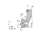
図9に示すように、3つに分岐された油路のうちの1つの油路321は、直交する複数の直線状の油路により構成されている。また、油路321には、油圧センサ35が差し込まれている。また、油路321には、オリフィス33が配置されている。また、油路321は、ギヤ機構200内に設けられた油路213に接続されている。油路321は、油路213に液密的に接続されている。
As shown in FIG. 9, one
図10に示すように、油路322は、直交する複数の直線状の油路により構成されている。また、油路322には、油路322を封止するための栓部材41が差し込まれている。また、油路322には、オリフィス33が配置されている。また、油路322は、ギヤ機構200内に設けられた油路214に液密的に接続されている。
As shown in FIG. 10, the
図11に示すように、油路323は、直交する複数の直線状の油路により構成されている。また、油路323には、油圧センサ35が差し込まれている。また、油路323には、オリフィス33が配置されている。また、油路323は、ギヤ機構200内に設けられた油路215に液密的に接続されている。なお、油路215は、ギヤ機構200の油路分配部材30が配置される側(Y1方向側)から、油路分配部材30とは反対側(Y2方向側)まで延びるように形成されている。なお、油路215の開口部分には、栓部材41が差し込まれている。
As shown in FIG. 11, the
また、図3および図4に示すように、3つに分岐された油路321、油路322および油路323は、それぞれ、ギヤ機構200に突出するように設けられたボス状の油路213、油路214および油路215に液密的に接続されている。
As shown in FIGS. 3 and 4, the
次に、図1を参照して、油の流れについて説明する。 Next, the flow of oil will be described with reference to FIG.
オイルクーラ20により冷却された油は、油路321を介して冷却油としてモータジェネレータ205側に供給される。また、オイルクーラ20により冷却された油は、油路322および油路323を介して、潤滑油として軸受け203、軸受け209、オイルシール206、ギヤ204およびギヤ210側に供給される。そして、冷却油および潤滑油としてとして使用された油は、ギヤ機構200から油路31aを介して電動ポンプ部10の吸入口12に吸入される。そして、電動ポンプ部10の吐出口11から吐出された油は、油路31bおよび油路32aを介して、オイルクーラ20に導入されて冷却される。
The oil cooled by the
(本実施形態の効果)
本実施形態では、以下のような効果を得ることができる。
(Effect of this embodiment)
In the present embodiment, the following effects can be obtained.
本実施形態では、上記のように、電動ポンプ部10とオイルクーラ20とが設けられ、電動ポンプ部10に接続される油路31と、オイルクーラ20に接続される油路32とを内部に含む油路分配部材30を備える。これにより、電動ポンプ部10に接続される油路31とオイルクーラ20に接続される油路32とが油路分配部材30の内部に配置されるので、電動ポンプ部10やオイルクーラ20に接続される油路をオイルポンプユニット100の外側に飛び出すように配置される配管により構成する場合と異なり、オイルポンプユニット100が大型化するのを抑制することができる。
In the present embodiment, as described above, the
また、電動ポンプ部10に接続される油路31とオイルクーラ20に接続される油路32とが油路分配部材30の内部に配置されるので、油路31と油路32とを油路分配部材30内に集中して(近接して)配置することができる。これにより、油路31と油路32とを別個の部材(配管など)により構成する場合と異なり、部品点数の増加および構成の複雑化を抑制することができるとともに、オイルポンプユニット100が大型化するのをより抑制することができる。
Further, since the
また、電動ポンプ部10とオイルクーラ20とが油路分配部材30に設けられているので、電動ポンプ部10、オイルクーラ20および油路分配部材30を一体化した状態でギヤ機構200に取り付けることができる。これにより、電動ポンプ部10とオイルクーラ20とを個別にギヤ機構200に取り付けた後に、電動ポンプ部10、オイルクーラ20およびギヤ機構200をそれぞれ配管により接続する場合と異なり、電動ポンプ部10およびオイルクーラ20の取り付け作業を簡略化することができる。また、電動ポンプ部10およびオイルクーラ20を直接ギヤ機構200に取り付ける場合と異なり、ギヤ機構200に電動ポンプ部10およびオイルクーラ20を取り付けるためのスペースを設ける必要がない。
Moreover, since the
また、本実施形態では、上記のように、油路31に、電動ポンプ部10の吐出口11と吸入口12とを液密的に接続して、油路32に、オイルクーラ20の排出口21と導入口22とを液密的に接続する。これにより、油路31と電動ポンプ部10の吐出口11および吸入口12とを(油路32とオイルクーラ20の排出口21および導入口22とを)配管を介して接続する場合と異なり、オイルポンプユニット100が大型化するのをさらに抑制することができる。
Further, in the present embodiment, as described above, the
また、本実施形態では、上記のように、油路分配部材30は、板形状を有し、板形状の油路分配部材30の面30aにオイルクーラ20を設けるとともに、面30aとは異なる面30bに電動ポンプ部10を設ける。これにより、オイルクーラ20と電動ポンプ部10とが異なる面に配置されるので、オイルクーラ20と電動ポンプ部10とを同一の面に並列するように配置する場合と比べて、板形状の油路分配部材30を構成する1つの面の大きさ(すなわち、板形状の油路分配部材30の大きさ)を小さくすることができる。その結果、油路分配部材30内に設けられる油路31および油路32の長さが長くなることを抑制することができる。
Further, in the present embodiment, as described above, the oil
また、本実施形態では、上記のように、面30aは、油路分配部材30のギヤ機構200に配置される側とは反対側の面であり、面30bは、面30aに直交する油路分配部の側面である。これにより、電動ポンプ部10からの油の吐出方向(吸入方向)と、オイルクーラ20からの油の排出方向(導入方向)とを直交させることができるので、電動ポンプ部10とオイルクーラ20とを接続する油路を直交する直線状の油路により構成することができる。これにより、電動ポンプ部10とオイルクーラ20とを接続する油路が湾曲している場合と異なり、油路の長さが長くなるのを抑制することができる。
In the present embodiment, as described above, the
また、本実施形態では、上記のように、油路32に、油の流量を調整するためのオリフィス33を設ける。これにより、オリフィス33が油路分配部材30内の油路32に取り付けられるので、電動ポンプ部10、オイルクーラ20および油路分配部材30に加えて、オリフィス33も一体化した状態でギヤ機構200に取り付けることができる。また、オリフィス33により油の流量(液量)を調整することができるので、電動ポンプ部10の容量を適切に設定する(小さくする)ことができる。すなわち、電動ポンプ部10の容量が過度に大きく設定されるのを抑制することができる。
In the present embodiment, as described above, the
また、本実施形態では、上記のように、油路分配部材30に、油の状態を検知する温度センサ34および油圧センサ35を設ける。これにより、温度センサ34および油圧センサ35が油路分配部材30内に取り付けられるので、電動ポンプ部10、オイルクーラ20および油路分配部材30に加えて、温度センサ34および油圧センサ35も一体化した状態でギヤ機構200に取り付けることができる。また、温度センサ34および油圧センサ35により検知された油の状態に基づいて、電動ポンプ部10の運転を最適化することができる。
In the present embodiment, as described above, the oil
また、本実施形態では、上記のように、油路32を、オイルクーラ20から排出された油を分岐して、ギヤ機構200に導入するように構成する。これにより、オイルクーラ20から流出した油を異なる用途(冷却、潤滑)に使用することができる。
In the present embodiment, as described above, the
また、本実施形態では、上記のように、油路31および油路32を、それぞれ、直交する複数の直線状の油路により構成する。これにより、ドリルなどの工具によって油路分配部材30に孔を開けることにより、容易に、油路を形成することができる。
In the present embodiment, as described above, the
[変形例]
今回開示された実施形態は、全ての点で例示であり制限的なものではないと考えられるべきである。本発明の範囲は上記実施形態の説明ではなく特許請求の範囲によって示され、さらに特許請求の範囲と均等の意味および範囲内での全ての変更(変形例)が含まれる。
[Modification]
It should be thought that embodiment disclosed this time is an illustration and restrictive at no points. The scope of the present invention is shown not by the description of the above embodiment but by the scope of claims for patent, and further includes all modifications (modifications) within the meaning and scope equivalent to the scope of claims for patent.
たとえば、上記実施形態では、循環する流体が油である例を示したが、本発明はこれに限られない。たとえば、油以外の水などの流体が循環するポンプユニットに本発明を適用してもよい。 For example, in the above-described embodiment, the example in which the circulating fluid is oil is shown, but the present invention is not limited to this. For example, the present invention may be applied to a pump unit in which a fluid such as water other than oil circulates.
また、上記実施形態では、油路分配部材が板形状を有する例を示したが、本発明はこれに限られない。本発明では、ギヤ機構、電動ポンプ部およびオイルクーラに接続される油路が内部に形成されていれば、油路分配部材の形状は板形状以外の形状でもよい。 Moreover, in the said embodiment, although the oil-path distribution member showed the example which has plate shape, this invention is not limited to this. In the present invention, as long as the oil passage connected to the gear mechanism, the electric pump unit, and the oil cooler is formed inside, the shape of the oil passage distribution member may be other than the plate shape.
また、上記実施形態では、油路分配部材のギヤ機構に配置される側とは反対側の面にオイルクーラを設け、油路分配部材の側面に電動ポンプ部を設ける例を示したが、本発明はこれに限られない。たとえば、オイルクーラおよび電動ポンプ部を、ギヤ機構に配置される側とは反対側の面および側面以外の面に設けてもよい。 In the above embodiment, an example in which the oil cooler is provided on the surface opposite to the side where the oil passage distribution member is disposed on the gear mechanism and the electric pump portion is provided on the side surface of the oil passage distribution member is shown. The invention is not limited to this. For example, you may provide an oil cooler and an electric pump part in surfaces other than the surface and side surface opposite to the side arrange | positioned at a gear mechanism.
また、上記実施形態では、オリフィスが、オイルクーラから排出された油が流通する油路に設けられる例を示したが、本発明はこれに限られない。たとえば、オリフィスを、オイルクーラに油が導入される側や、電動ポンプ部に油が吸入される側などに設けてもよい。 Moreover, although the orifice was provided in the oil path through which the oil discharged | emitted from the oil cooler distribute | circulated in the said embodiment, this invention is not limited to this. For example, the orifice may be provided on the side where oil is introduced into the oil cooler, or on the side where oil is sucked into the electric pump unit.
また、上記実施形態では、オイルポンプユニット(油路分配部材)に温度センサと油圧センサとを設ける例を示したが、本発明はこれに限られない。たとえば、オイルポンプユニット(油路分配部材)に、温度センサおよび油圧センサ以外のセンサ(油量センサなど)を設けてもよい。 Moreover, although the example which provides a temperature sensor and a hydraulic pressure sensor in the oil pump unit (oil path distribution member) was shown in the said embodiment, this invention is not limited to this. For example, a sensor (such as an oil amount sensor) other than the temperature sensor and the hydraulic pressure sensor may be provided in the oil pump unit (oil passage distribution member).
また、上記実施形態では、オイルクーラから排出された油が3つの油路に分岐される例を示したが、本発明はこれに限られない。たとえば、オイルクーラから排出された油が、3つ以外の数の油路に分岐されていてもよいし、分岐されなくてもよい。 Moreover, in the said embodiment, although the oil discharged | emitted from the oil cooler showed the example branched to three oil paths, this invention is not limited to this. For example, the oil discharged from the oil cooler may be branched into a number of oil passages other than three, or may not be branched.
また、上記実施形態では、油路が、直交する(略90度の角度で交差する)複数の直線状の油路により構成されている例を示したが、本発明はこれに限られない。たとえば、油路が、90度以外の角度で交差する複数の直線状の油路により構成されていてもよい。 In the above-described embodiment, an example in which the oil passage is configured by a plurality of linear oil passages that intersect at right angles (intersect at an angle of approximately 90 degrees) has been described, but the present invention is not limited thereto. For example, the oil passage may be configured by a plurality of linear oil passages that intersect at an angle other than 90 degrees.
10 電動ポンプ部
11 吐出口
12 吸入口
20 オイルクーラ(冷却部)
21 排出口
22 導入口
30 油路分配部材(流路分配部材)
30a 面(第1の面)
30b 面(第2の面)
31 油路(第1流路)
32 油路(第2流路)
33 オリフィス
34 温度センサ(検知部)
35 油圧センサ(検知部)
100 オイルポンプユニット(流体ポンプユニット)
200 ギヤ機構
DESCRIPTION OF
21
30a surface (first surface)
30b surface (second surface)
31 Oil passage (first passage)
32 Oil passage (second passage)
33
35 Hydraulic sensor (detector)
100 Oil pump unit (fluid pump unit)
200 Gear mechanism
Claims (6)
前記循環される流体を冷却するための冷却部と、
前記ギヤ機構に配置されるとともに、前記電動ポンプ部と前記冷却部とが設けられ、前記電動ポンプ部に接続される第1流路と、前記冷却部に接続される第2流路とを内部に含む流路分配部材とを備える、流体ポンプユニット。 An electric pump for circulating fluid in the gear mechanism;
A cooling unit for cooling the circulated fluid;
The electric pump part and the cooling part are provided in the gear mechanism, and a first flow path connected to the electric pump part and a second flow path connected to the cooling part are provided inside. A fluid pump unit comprising a flow path distribution member included in the above.
板形状の前記流路分配部材の第1の面に前記冷却部が設けられるとともに、前記第1の面とは異なる第2の面に前記電動ポンプ部が設けられている、請求項1または2に記載の流体ポンプユニット。 The flow path distribution member has a plate shape,
The said cooling part is provided in the 1st surface of the said flow path distribution member of plate shape, and the said electric pump part is provided in the 2nd surface different from the said 1st surface. The fluid pump unit described in 1.
Priority Applications (4)
| Application Number | Priority Date | Filing Date | Title |
|---|---|---|---|
| JP2016013920A JP2017133594A (en) | 2016-01-28 | 2016-01-28 | Fluid pump unit |
| CN201710058123.4A CN107013670A (en) | 2016-01-28 | 2017-01-23 | Fluid pump unit |
| US15/418,073 US20170219083A1 (en) | 2016-01-28 | 2017-01-27 | Fluid pump unit |
| EP17153466.2A EP3199838B1 (en) | 2016-01-28 | 2017-01-27 | Fluid pump unit |
Applications Claiming Priority (1)
| Application Number | Priority Date | Filing Date | Title |
|---|---|---|---|
| JP2016013920A JP2017133594A (en) | 2016-01-28 | 2016-01-28 | Fluid pump unit |
Publications (1)
| Publication Number | Publication Date |
|---|---|
| JP2017133594A true JP2017133594A (en) | 2017-08-03 |
Family
ID=57914823
Family Applications (1)
| Application Number | Title | Priority Date | Filing Date |
|---|---|---|---|
| JP2016013920A Pending JP2017133594A (en) | 2016-01-28 | 2016-01-28 | Fluid pump unit |
Country Status (4)
| Country | Link |
|---|---|
| US (1) | US20170219083A1 (en) |
| EP (1) | EP3199838B1 (en) |
| JP (1) | JP2017133594A (en) |
| CN (1) | CN107013670A (en) |
Cited By (2)
| Publication number | Priority date | Publication date | Assignee | Title |
|---|---|---|---|---|
| WO2019187076A1 (en) * | 2018-03-30 | 2019-10-03 | シャープ株式会社 | Display device |
| WO2023182446A1 (en) * | 2022-03-23 | 2023-09-28 | ジヤトコ株式会社 | Power transmission device |
Families Citing this family (7)
| Publication number | Priority date | Publication date | Assignee | Title |
|---|---|---|---|---|
| JP6545217B2 (en) * | 2017-03-24 | 2019-07-17 | 本田技研工業株式会社 | Lubricating fluid supply structure of power transmission device |
| FR3096428B1 (en) * | 2019-05-24 | 2022-01-21 | Renault Sas | METHOD FOR COOLING THE INTERNAL MECHANISMS OF A VEHICLE SPEED REDUCER AND COOLING LUBRICATION GUTTER |
| CN114837792A (en) | 2021-03-10 | 2022-08-02 | 美普盛(上海)汽车零部件有限公司 | Electric coolant pump with expansion compensation sealing element |
| CA3164743A1 (en) * | 2021-06-21 | 2022-12-21 | Nott Company | Electronic pump and methods of using the same |
| JP2023067110A (en) * | 2021-10-29 | 2023-05-16 | ニデック株式会社 | Drive device |
| DE102021130151A1 (en) | 2021-11-18 | 2023-05-25 | Audi Aktiengesellschaft | Drive device for an electrified vehicle axle |
| DE102022109970A1 (en) * | 2022-04-26 | 2023-10-26 | Audi Aktiengesellschaft | Geared motor for a motor vehicle and motor vehicle with a geared motor |
Citations (9)
| Publication number | Priority date | Publication date | Assignee | Title |
|---|---|---|---|---|
| JP2003106418A (en) * | 2001-09-28 | 2003-04-09 | Jatco Ltd | Automatic transmission |
| JP2005188612A (en) * | 2003-12-25 | 2005-07-14 | Nissan Motor Co Ltd | Driver for vehicle |
| JP2005265014A (en) * | 2004-03-17 | 2005-09-29 | Kubota Corp | Working fluid cooling device for working vehicle |
| JP2005344938A (en) * | 2005-09-05 | 2005-12-15 | Aisin Aw Co Ltd | Automatic transmission with auxiliary hydraulic unit |
| JP2007321927A (en) * | 2006-06-02 | 2007-12-13 | Toyota Motor Corp | Lubricating device for vehicular driving device |
| JP2009216107A (en) * | 2008-03-07 | 2009-09-24 | Mazda Motor Corp | Automatic transmission |
| JP2010216416A (en) * | 2009-03-18 | 2010-09-30 | Honda Motor Co Ltd | Oil cooler mounting structure and v-type engine equipped with the same |
| JP2013068293A (en) * | 2011-09-23 | 2013-04-18 | Hitachi Constr Mach Co Ltd | Bubble removing device for sensor fitting hole |
| JP2014074486A (en) * | 2012-10-05 | 2014-04-24 | Honda Motor Co Ltd | Driving device for vehicle |
Family Cites Families (7)
| Publication number | Priority date | Publication date | Assignee | Title |
|---|---|---|---|---|
| JPH0689842B2 (en) * | 1985-12-25 | 1994-11-14 | スズキ株式会社 | Coolant control device for continuously variable transmission |
| FR2684156B1 (en) * | 1991-11-26 | 1994-01-14 | Peugeot Automobiles | WATER COOLING DEVICE FOR AN AUTOMATIC TRANSMISSION. |
| JP3056608B2 (en) | 1993-02-03 | 2000-06-26 | 新潟コンバーター株式会社 | Transmission with rotary cooler |
| US6467578B1 (en) * | 2000-05-17 | 2002-10-22 | Lockheed Martin Corporation | Gear baffle windage test rig |
| JP2006300122A (en) * | 2005-04-18 | 2006-11-02 | Toyota Motor Corp | Oil passage structure |
| JP5019135B2 (en) * | 2009-03-30 | 2012-09-05 | アイシン・エィ・ダブリュ株式会社 | Vehicle drive device |
| ES2496417T3 (en) * | 2011-11-30 | 2014-09-19 | Siemens Aktiengesellschaft | Gear for industrial applications or wind power installations |
-
2016
- 2016-01-28 JP JP2016013920A patent/JP2017133594A/en active Pending
-
2017
- 2017-01-23 CN CN201710058123.4A patent/CN107013670A/en active Pending
- 2017-01-27 EP EP17153466.2A patent/EP3199838B1/en not_active Not-in-force
- 2017-01-27 US US15/418,073 patent/US20170219083A1/en not_active Abandoned
Patent Citations (9)
| Publication number | Priority date | Publication date | Assignee | Title |
|---|---|---|---|---|
| JP2003106418A (en) * | 2001-09-28 | 2003-04-09 | Jatco Ltd | Automatic transmission |
| JP2005188612A (en) * | 2003-12-25 | 2005-07-14 | Nissan Motor Co Ltd | Driver for vehicle |
| JP2005265014A (en) * | 2004-03-17 | 2005-09-29 | Kubota Corp | Working fluid cooling device for working vehicle |
| JP2005344938A (en) * | 2005-09-05 | 2005-12-15 | Aisin Aw Co Ltd | Automatic transmission with auxiliary hydraulic unit |
| JP2007321927A (en) * | 2006-06-02 | 2007-12-13 | Toyota Motor Corp | Lubricating device for vehicular driving device |
| JP2009216107A (en) * | 2008-03-07 | 2009-09-24 | Mazda Motor Corp | Automatic transmission |
| JP2010216416A (en) * | 2009-03-18 | 2010-09-30 | Honda Motor Co Ltd | Oil cooler mounting structure and v-type engine equipped with the same |
| JP2013068293A (en) * | 2011-09-23 | 2013-04-18 | Hitachi Constr Mach Co Ltd | Bubble removing device for sensor fitting hole |
| JP2014074486A (en) * | 2012-10-05 | 2014-04-24 | Honda Motor Co Ltd | Driving device for vehicle |
Cited By (2)
| Publication number | Priority date | Publication date | Assignee | Title |
|---|---|---|---|---|
| WO2019187076A1 (en) * | 2018-03-30 | 2019-10-03 | シャープ株式会社 | Display device |
| WO2023182446A1 (en) * | 2022-03-23 | 2023-09-28 | ジヤトコ株式会社 | Power transmission device |
Also Published As
| Publication number | Publication date |
|---|---|
| CN107013670A (en) | 2017-08-04 |
| EP3199838A1 (en) | 2017-08-02 |
| EP3199838B1 (en) | 2018-12-05 |
| US20170219083A1 (en) | 2017-08-03 |
Similar Documents
| Publication | Publication Date | Title |
|---|---|---|
| JP2017133594A (en) | Fluid pump unit | |
| CN107757838B (en) | Gyroscope stabilizer | |
| US8601997B2 (en) | Water pump with integrated oil cooler | |
| US9482225B2 (en) | Gear pump, pumping apparatus including the same, and aircraft fuel system including gear pump | |
| WO2013153782A1 (en) | Fuel cell system | |
| CN102840237A (en) | Liquid hydrostatic bearing capable of realizing oil distribution from end surface | |
| US11314295B2 (en) | Pressurized infusion device and liquid cooling system | |
| WO2020059786A1 (en) | Transmission lubrication structure for helicopter | |
| JP6582468B2 (en) | Rotating electrical machine structure | |
| CA2933621C (en) | Hydraulic line routing plate | |
| WO2011148692A1 (en) | Water pump | |
| WO2019124045A1 (en) | Liquid supply mechanism | |
| JP5277773B2 (en) | transmission | |
| US20120257848A1 (en) | Slide bearing | |
| GB2493626A (en) | Fluid flow control device | |
| JP2015129540A (en) | Lubrication device of vehicular transmission | |
| US20200049248A1 (en) | Lubrication System of Power Assembly of Electric Scooter | |
| JP2005291316A (en) | Flow passage structure of transmission | |
| JP3895158B2 (en) | Forced circulation bathtub connecting device | |
| US9915263B2 (en) | Gear pump with deflector in fluid intake for diverting fluid towards voids in housing | |
| KR101381403B1 (en) | Centrifugal pump of leakage fluid circulation through shaft | |
| KR200467905Y1 (en) | Lubrication Oil Cooler in/outlet pipe module base frame | |
| JP6941072B2 (en) | Gear device | |
| US9951771B2 (en) | Selectable flow hydraulic gear pump | |
| JP6779179B2 (en) | Hydraulic circuit |
Legal Events
| Date | Code | Title | Description |
|---|---|---|---|
| A621 | Written request for application examination |
Free format text: JAPANESE INTERMEDIATE CODE: A621 Effective date: 20181210 |
|
| A131 | Notification of reasons for refusal |
Free format text: JAPANESE INTERMEDIATE CODE: A131 Effective date: 20191001 |
|
| A02 | Decision of refusal |
Free format text: JAPANESE INTERMEDIATE CODE: A02 Effective date: 20200331 |