JP2017126219A - Driving support device - Google Patents
Driving support device Download PDFInfo
- Publication number
- JP2017126219A JP2017126219A JP2016005473A JP2016005473A JP2017126219A JP 2017126219 A JP2017126219 A JP 2017126219A JP 2016005473 A JP2016005473 A JP 2016005473A JP 2016005473 A JP2016005473 A JP 2016005473A JP 2017126219 A JP2017126219 A JP 2017126219A
- Authority
- JP
- Japan
- Prior art keywords
- vehicle
- intersection
- driving support
- reliability
- map matching
- Prior art date
- Legal status (The legal status is an assumption and is not a legal conclusion. Google has not performed a legal analysis and makes no representation as to the accuracy of the status listed.)
- Granted
Links
- 238000000034 method Methods 0.000 claims description 49
- 238000004891 communication Methods 0.000 claims description 28
- 230000007704 transition Effects 0.000 claims description 5
- 238000012986 modification Methods 0.000 description 19
- 230000004048 modification Effects 0.000 description 19
- 230000002093 peripheral effect Effects 0.000 description 13
- 238000012545 processing Methods 0.000 description 6
- 230000001133 acceleration Effects 0.000 description 5
- 238000001514 detection method Methods 0.000 description 2
- 238000010586 diagram Methods 0.000 description 2
- 238000012937 correction Methods 0.000 description 1
Images


Classifications
-
- G—PHYSICS
- G01—MEASURING; TESTING
- G01C—MEASURING DISTANCES, LEVELS OR BEARINGS; SURVEYING; NAVIGATION; GYROSCOPIC INSTRUMENTS; PHOTOGRAMMETRY OR VIDEOGRAMMETRY
- G01C21/00—Navigation; Navigational instruments not provided for in groups G01C1/00 - G01C19/00
- G01C21/26—Navigation; Navigational instruments not provided for in groups G01C1/00 - G01C19/00 specially adapted for navigation in a road network
- G01C21/28—Navigation; Navigational instruments not provided for in groups G01C1/00 - G01C19/00 specially adapted for navigation in a road network with correlation of data from several navigational instruments
- G01C21/30—Map- or contour-matching
-
- H—ELECTRICITY
- H04—ELECTRIC COMMUNICATION TECHNIQUE
- H04W—WIRELESS COMMUNICATION NETWORKS
- H04W4/00—Services specially adapted for wireless communication networks; Facilities therefor
- H04W4/30—Services specially adapted for particular environments, situations or purposes
- H04W4/40—Services specially adapted for particular environments, situations or purposes for vehicles, e.g. vehicle-to-pedestrians [V2P]
-
- B—PERFORMING OPERATIONS; TRANSPORTING
- B60—VEHICLES IN GENERAL
- B60W—CONJOINT CONTROL OF VEHICLE SUB-UNITS OF DIFFERENT TYPE OR DIFFERENT FUNCTION; CONTROL SYSTEMS SPECIALLY ADAPTED FOR HYBRID VEHICLES; ROAD VEHICLE DRIVE CONTROL SYSTEMS FOR PURPOSES NOT RELATED TO THE CONTROL OF A PARTICULAR SUB-UNIT
- B60W30/00—Purposes of road vehicle drive control systems not related to the control of a particular sub-unit, e.g. of systems using conjoint control of vehicle sub-units
- B60W30/08—Active safety systems predicting or avoiding probable or impending collision or attempting to minimise its consequences
-
- G—PHYSICS
- G08—SIGNALLING
- G08G—TRAFFIC CONTROL SYSTEMS
- G08G1/00—Traffic control systems for road vehicles
- G08G1/09—Arrangements for giving variable traffic instructions
- G08G1/0962—Arrangements for giving variable traffic instructions having an indicator mounted inside the vehicle, e.g. giving voice messages
- G08G1/09626—Arrangements for giving variable traffic instructions having an indicator mounted inside the vehicle, e.g. giving voice messages where the origin of the information is within the own vehicle, e.g. a local storage device, digital map
-
- G—PHYSICS
- G08—SIGNALLING
- G08G—TRAFFIC CONTROL SYSTEMS
- G08G1/00—Traffic control systems for road vehicles
- G08G1/16—Anti-collision systems
- G08G1/161—Decentralised systems, e.g. inter-vehicle communication
- G08G1/163—Decentralised systems, e.g. inter-vehicle communication involving continuous checking
-
- H—ELECTRICITY
- H04—ELECTRIC COMMUNICATION TECHNIQUE
- H04W—WIRELESS COMMUNICATION NETWORKS
- H04W4/00—Services specially adapted for wireless communication networks; Facilities therefor
- H04W4/02—Services making use of location information
- H04W4/024—Guidance services
-
- H—ELECTRICITY
- H04—ELECTRIC COMMUNICATION TECHNIQUE
- H04W—WIRELESS COMMUNICATION NETWORKS
- H04W4/00—Services specially adapted for wireless communication networks; Facilities therefor
- H04W4/02—Services making use of location information
- H04W4/029—Location-based management or tracking services
-
- H—ELECTRICITY
- H04—ELECTRIC COMMUNICATION TECHNIQUE
- H04W—WIRELESS COMMUNICATION NETWORKS
- H04W4/00—Services specially adapted for wireless communication networks; Facilities therefor
- H04W4/30—Services specially adapted for particular environments, situations or purposes
- H04W4/40—Services specially adapted for particular environments, situations or purposes for vehicles, e.g. vehicle-to-pedestrians [V2P]
- H04W4/46—Services specially adapted for particular environments, situations or purposes for vehicles, e.g. vehicle-to-pedestrians [V2P] for vehicle-to-vehicle communication [V2V]
Landscapes
- Engineering & Computer Science (AREA)
- Radar, Positioning & Navigation (AREA)
- Remote Sensing (AREA)
- Physics & Mathematics (AREA)
- General Physics & Mathematics (AREA)
- Automation & Control Theory (AREA)
- Computer Networks & Wireless Communication (AREA)
- Signal Processing (AREA)
- Transportation (AREA)
- Mechanical Engineering (AREA)
- Navigation (AREA)
- Traffic Control Systems (AREA)
Abstract
Description
本発明は、車両の運転者の運転を支援する運転支援装置に関し、特に、車両同士の衝突可能性を予測して運転支援を行う装置に関する。 The present invention relates to a driving support device that supports driving of a vehicle driver, and more particularly, to a device that supports driving by predicting the possibility of collision between vehicles.
車両同士の衝突可能性を予測して運転支援を行う装置が知られている。たとえば、特許文献1では、運転支援装置を搭載した車両が、他車両との間で相互通信を行いつつ、道路地図情報に基づいて、運転支援装置を搭載した車両(以下、自車両)と他車両の将来の予測車両位置をそれぞれ予測する。そして、将来の時刻における自車両の予測車両位置と、その将来の時刻における他車両の予測車両位置を比較する。比較した結果、自車両の予測車両位置と他車両の予測車両位置が近い場合に、自車両と他車両とが衝突する可能性があると判定して、安全支援情報を提供する。
An apparatus that performs driving support by predicting the possibility of collision between vehicles is known. For example, in
特許文献1の技術では、道路地図情報により表される道路上における自車両の位置を予測する必要がある。このためには、自車両の現在位置を逐次決定する必要がある。現在位置を決定する方法としては、GNSS(Global Navigation Satellite System)が備える航法衛星が送信する航法信号を受信して、この航法信号に基づいて現在位置を決定する方法が広く知られている。ただし、航法信号に基づいて決定する現在位置(以下、GNSS現在位置)には位置決定誤差があり、この誤差により、実際には道路を走行しているにも関わらず、GNSS現在位置は道路上に決定されないことがあることも広く知られている。
In the technique of
GNSS現在位置を補正する技術として、マップマッチングが広く知られている。マップマッチングは、逐次決定する現在位置の軌跡を道路形状にマッチングさせることで、現在位置を道路上に補正する。 Map matching is widely known as a technique for correcting the current position of the GNSS. Map matching corrects the current position on the road by matching the trajectory of the current position determined sequentially with the road shape.
しかし、マップマッチングは、車両の走行軌跡に似ている道路形状が現在位置付近にあれば、走行軌跡に完全には一致していなくても、車両の現在位置を、走行軌跡に似ている道路形状を有する道路上に補正してしまう。そのため、場合によっては、現在位置を、実際に車両が走行している道路とは異なる道路に補正してしまうこともある。 However, in map matching, if the road shape that resembles the travel locus of the vehicle is near the current position, the current position of the vehicle is similar to the travel locus even if it does not completely match the travel locus. It corrects on the road which has a shape. For this reason, in some cases, the current position may be corrected to a road different from the road on which the vehicle is actually traveling.
そのため、常に、マップマッチングにより補正された現在位置に基づいて運転支援を行うと、運転支援が行われるべき状況において、運転支援が行われない恐れが生じる。 Therefore, when driving assistance is always performed based on the current position corrected by map matching, there is a risk that driving assistance will not be performed in a situation where driving assistance should be performed.
一方、マップマッチングをしないで、GNSS現在位置と進行方向とに基づいて自車両の位置および他車両の位置を予測ことも考えられる。マップマッチングをしなければ、現在位置が、実際には走行していない道路上に補正されてしまうことによって運転支援が行われない、という問題は生じない。 On the other hand, it is also conceivable to predict the position of the host vehicle and the positions of other vehicles based on the current GNSS position and the traveling direction without performing map matching. Without map matching, there is no problem that driving support is not performed because the current position is corrected on a road that is not actually running.
しかし、マップマッチングをしないと、自車両が走行している道路と他車両が走行している道路とが交わらないにも関わらず、自車両と他車両が衝突する可能性があると判断して、不要な運転支援を実行してしまう恐れが生じる。 However, if map matching is not performed, it is determined that there is a possibility of collision between the host vehicle and the other vehicle even though the road on which the host vehicle is traveling does not intersect with the road on which the other vehicle is traveling. This may cause unnecessary driving assistance.
本発明は、この事情に基づいて成されたものであり、その目的とするところは、運転支援が必要な状況であるのに運転支援が行われないことを抑制しつつ、不要な運転支援が行われてしまうことも抑制できる運転支援装置を提供することにある。 The present invention has been made based on this situation, and the purpose of the present invention is to prevent unnecessary driving assistance while suppressing that driving assistance is not performed even though driving assistance is necessary. An object of the present invention is to provide a driving support device that can suppress the occurrence of the operation.
上記目的は独立請求項に記載の特徴の組み合わせにより達成され、また、下位請求項は、発明の更なる有利な具体例を規定する。特許請求の範囲に記載した括弧内の符号は、一つの態様として後述する実施形態に記載の具体的手段との対応関係を示すものであって、本発明の技術的範囲を限定するものではない。 The above object is achieved by a combination of the features described in the independent claims, and the subclaims define further advantageous embodiments of the invention. Reference numerals in parentheses described in the claims indicate a correspondence relationship with specific means described in the embodiments described later as one aspect, and do not limit the technical scope of the present invention. .
上記目的を達成するための本発明は、車両で用いられ、車両の運転者の運転を支援する制御を行う運転支援部(S12、S17、S18)を備えた運転支援装置であって、
衛星航法システムが備える航法衛星が送信する航法信号を受信して決定した位置を逐次取得して、運転支援装置が用いられている車両である自車両の現在位置を逐次決定する自車位置決定部(S1)と、
自車両の現在位置の軌跡と道路形状との比較に基づいて自車両の現在位置を道路上に補正するマップマッチングの信頼度を逐次決定する信頼度決定部(S6)と、
自車両の現在位置と自車両の進行方位とから、自車両の今後の走行軌道である自車両予測軌道を予測する自車両予測部(S3)と、
自車両の周辺に存在している周辺車両の現在位置と周辺車両の進行方位とから予測される周辺車両の今後の走行軌道である周辺車両予測軌道を予測するための軌道予測情報を、自車両に備えられている車車間通信部から取得して、周辺車両の今後の走行軌道である周辺車両予測軌道を予測する周辺車両予測部(S5)と、
自車両予測軌道と周辺車両予測軌道に交点がある場合に、交点を含むように判定領域を設定する領域設定部(S13)と、
信頼度決定部が決定したマップマッチングの信頼度が、予め設定された高信頼度であることに基づいて、交差点を交差点ノードで表している道路地図情報から、マップマッチングにより決定した自車両の現在位置が位置する道路において、自車両の進行方向に存在する交差点ノードを決定する交差点ノード決定部(S9)と、
領域設定部が設定した判定領域内に、交差点ノード決定部が決定した交差点ノードがあるか否かを判定する判定部(S16)とを備え、
運転支援部は、
判定領域内に交差点ノードがない場合、判定領域内に交差点ノードがある場合よりも、運転支援レベルを運転支援が抑制されるレベルとし、
信頼度決定部が決定したマップマッチングの信頼度が、予め設定された低信頼度である場合、判定部による判定を行うことなく、自車位置決定部が決定した自車両の現在位置と自車両の進行方位とから自車両予測部が予測した自車両予測軌道と、周辺車両予測軌道に交点があるか否かに基づいて運転支援を実行するか否かを決定する。
The present invention for achieving the above object is a driving support device including a driving support unit (S12, S17, S18) that is used in a vehicle and performs control for supporting driving of the driver of the vehicle.
The own vehicle position determination unit that sequentially acquires the position determined by receiving the navigation signal transmitted by the navigation satellite provided in the satellite navigation system and sequentially determines the current position of the own vehicle that is the vehicle in which the driving support device is used. (S1),
A reliability determination unit (S6) for sequentially determining the reliability of map matching for correcting the current position of the host vehicle on the road based on a comparison between the locus of the current position of the host vehicle and the road shape;
A host vehicle prediction unit (S3) that predicts a host vehicle predicted trajectory that is a future traveling track of the host vehicle from the current position of the host vehicle and the traveling direction of the host vehicle;
Trajectory prediction information for predicting the surrounding vehicle predicted trajectory, which is the future traveling track of the surrounding vehicle predicted from the current position of the surrounding vehicle and the traveling direction of the surrounding vehicle existing around the own vehicle, A surrounding vehicle prediction unit (S5) that obtains from a vehicle-to-vehicle communication unit included in the vehicle and predicts a surrounding vehicle predicted track that is a future traveling track of the surrounding vehicle;
An area setting unit (S13) for setting a determination area so as to include the intersection when the own vehicle predicted trajectory and the surrounding vehicle predicted trajectory have an intersection;
Based on the fact that the reliability of the map matching determined by the reliability determination unit is a high reliability set in advance, the current vehicle's current state determined by map matching from the road map information representing the intersection as an intersection node An intersection node determination unit (S9) for determining an intersection node existing in the traveling direction of the host vehicle on the road where the position is located;
A determination unit (S16) for determining whether or not there is an intersection node determined by the intersection node determination unit in the determination region set by the region setting unit;
The driving support department
When there is no intersection node in the determination area, the driving support level is set to a level at which driving support is suppressed, compared to the case where there is an intersection node in the determination area.
When the reliability of the map matching determined by the reliability determination unit is a low reliability set in advance, the current position of the host vehicle determined by the host vehicle position determination unit and the host vehicle without performing determination by the determination unit It is determined whether or not to perform driving support based on whether or not there is an intersection between the predicted vehicle trajectory predicted by the host vehicle prediction unit from the traveling direction of the vehicle and the predicted predicted track of the surrounding vehicle.
本発明によれば、マップマッチングの信頼度が高信頼度である場合、マップマッチングにより決定した自車両の現在位置が位置する道路上において自車両の進行方向に存在する交差点ノードを決定し、この交差点ノードが判定領域内にあるか否かを判定している。 According to the present invention, when the reliability of the map matching is high, the intersection node existing in the traveling direction of the host vehicle is determined on the road where the current position of the host vehicle determined by the map matching is located. It is determined whether or not the intersection node is within the determination area.
判定領域は、自車両予測軌道と周辺車両予測軌道に交点がある場合に、その交点を含むように設定する領域であるので、判定領域内に交差点ノードがある場合、自車両と周辺車両は同じ交差点を通過することが予想される。一方、判定領域内に交差点ノードがない場合、自車両と周辺車両は同じ交差点を通過しないことが予想される。 Since the determination area is an area that is set to include an intersection when there is an intersection between the own vehicle predicted trajectory and the surrounding vehicle predicted trajectory, the own vehicle and the surrounding vehicle are the same when there is an intersection node in the determination area. It is expected to pass through an intersection. On the other hand, when there is no intersection node in the determination area, it is expected that the host vehicle and the surrounding vehicle will not pass the same intersection.
車両同士の衝突は、通常、交差点で生じる。換言すれば、自車両予測軌道と周辺車両予測軌道とが交わる交点があっても、その交点が交差点でない場合には、自車両と周辺車両とが衝突する可能性は低いと考えられる。つまり、判定領域内に交差点ノードがあるか否かを判定することは、自車両と周辺車両との衝突可能性が高いか否かを判定していることになる。 A collision between vehicles usually occurs at an intersection. In other words, even if there is an intersection where the own vehicle predicted trajectory and the surrounding vehicle predicted trajectory intersect, if the intersection is not an intersection, the possibility that the own vehicle and the surrounding vehicle collide is low. That is, determining whether or not there is an intersection node in the determination region is determining whether or not there is a high possibility of a collision between the host vehicle and the surrounding vehicle.
判定領域内に交差点ノードがない場合、交点が交差点内でない可能性が高く、交点が交差点内でない場合には、自車両と周辺車両とが衝突する可能性は低いと考えられる。そこで、運転支援部は、判定領域内に交差点ノードがない場合、判定領域内に交差点ノードがある場合よりも、運転支援レベルを運転支援が抑制されるレベルとする。 If there is no intersection node in the determination area, there is a high possibility that the intersection is not within the intersection. If the intersection is not within the intersection, the possibility that the host vehicle and the surrounding vehicle collide is low. Therefore, the driving support unit sets the driving support level to a level at which driving support is suppressed when there is no intersection node in the determination region, compared to when there is an intersection node in the determination region.
したがって、本発明では、マップマッチングの信頼度が高信頼度である場合には、道路地図情報を活用して運転支援を抑制するか否かを判定する。これにより、不要な運転支援が行われてしまうことを抑制できる。 Therefore, in the present invention, when the reliability of the map matching is high, it is determined whether or not the driving support is suppressed using the road map information. Thereby, it can suppress that unnecessary driving assistance is performed.
一方、マップマッチングの信頼度が低信頼度である場合には、判定部による判定を行わない。つまり、マップマッチングの信頼度が低信頼度である場合には、道路地図情報を用いて運転支援を抑制するか否かを判定しない。そして、自車位置決定部が決定した自車両の現在位置と自車両の進行方位とから自車両予測部が予測した自車両予測軌道と、周辺車両予測軌道に交点があるか否かに基づいて運転支援を実行するか否かを決定する。これにより、運転支援が必要な状況であるのに運転支援が行われないことも抑制される。 On the other hand, when the reliability of the map matching is low, the determination by the determination unit is not performed. That is, when the reliability of map matching is low, it is not determined whether or not to suppress driving support using road map information. Then, based on whether or not there is an intersection between the own vehicle predicted trajectory predicted by the own vehicle predicting unit and the surrounding vehicle predicted trajectory predicted from the current position of the own vehicle determined by the own vehicle position determining unit and the traveling direction of the own vehicle Decide whether to perform driving assistance. Thereby, it is suppressed that driving assistance is not performed although driving assistance is required.
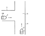
以下、本発明の実施形態を図面に基づいて説明する。図1に示すように、運転支援システム1を搭載した車両(以下、自車両)2は道路4を走行している。図1に示す状態では、自車両2の周辺には別の車両(以下、周辺車両)3が存在している。その周辺車両3は、自車両2が走行する道路4と交差する道路5を交差点6の方向に走行している。周辺車両3は運転支援システム100を搭載している。説明の便宜上、符号を異ならせているが、運転支援システム100は、運転支援システム1と同じ構成である。
Hereinafter, embodiments of the present invention will be described with reference to the drawings. As shown in FIG. 1, a vehicle (hereinafter, the host vehicle) 2 equipped with the driving
[運転支援システム1の構成]
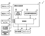
図2に示すように、運転支援システム1は、運転支援装置10、方位センサ20、車速センサ30、ヨーレートセンサ40、走行道路判定装置50、表示装置60、スピーカー70を備える。
[Configuration of driving support system 1]
As shown in FIG. 2, the driving
運転支援装置10は、GNSS受信部11、近距離無線通信部12、制御部13を備える。GNSS受信部11は、衛星航法システムであるGNSSが備える航法衛星が送信する航法信号を受信し、受信した航法信号に基づいて現在位置を逐次算出する。
The driving
近距離無線通信部12は、車車間通信および路車間通信を行うための通信部であり、5.9GHz帯や700MHz帯など所定の周波数帯の電波を用いて、他の車両に搭載された近距離無線通信装置および路側に設置された路側機との間で通信を行う。近距離無線通信部12は車車間通信を行うことができるので、請求項の車車間通信部に相当する。
The short-range
制御部13は、CPU、ROM、RAM等を備えたコンピュータであり、CPUが、RAMの一時記憶機能を利用しつつ、ROMなどの非遷移的実体的記録媒体(non-transitory tangible storage medium)に記憶されているプログラムを実行することで、後述する図5、図6に示す処理を実行する。また、図5、図6に示す処理を実行すると、プログラムに対応する方法が実行される。
The
また、制御部13は、図5、図6に示す処理の他に、後述する自車両情報を、逐次、近距離無線通信部12から、自車両2の周囲に送信する。
Moreover, the
方位センサ20は、自車両2の絶対方位を検出するためのセンサであり、たとえば、地磁気センサが用いられる。車速センサ30は自車両2の車速を逐次検出する。ヨーレートセンサ40は、このヨーレートセンサ40を通り、自車両2の垂直軸周りの回転角速度、すなわち、ヨーレートを検出する。
The
走行道路判定装置50は、道路地図情報を記憶している記憶部51、および、図示しない現在位置検出部を備えており、自車両2が走行している道路を逐次特定する。記憶部51に記憶されている道路地図情報は、道路をノード情報とリンク情報により表している。ノード情報は、ノードに関する情報であり、ノードは、道路を表現する上での結節点などを表している。このノードには交差点が含まれる。以下、交差点を表すノードを交差点ノードAとする。リンク情報は、ノードとノードの間を結ぶリンクに関する情報である。
The traveling
この走行道路判定装置50としては、たとえば、ナビゲーション装置を用いることができる。走行道路判定装置50の現在位置検出部は、公知のナビゲーション装置と同様、マップマッチングを行う。マップマッチングでは、GNSS受信機を用いて逐次検出した複数の現在位置から生成できる走行軌跡と道路地図形状とを比較して、自車両2の現在位置を、道路地図情報により表されているいずれかの道路上に補正する。道路地図情報は、リンクにより道路を表しているので、マップマッチングにより、自車両2の現在位置はリンク上に補正されることになる。
As the traveling
さらに、走行道路判定装置50は、マップマッチング状態を逐次決定している。本実施形態において、マップマッチング状態は、図3に示す4つの状態のいずれかである。MM0は、マップマッチングしていない状態である。換言すれば、MM0は、自車両2が位置するリンクを確定できていない未確定状態である。走行軌跡に類似する道路形状が、GNSS受信機を用いて検出した現在位置の周囲に存在しない場合などにMM0となる。
Furthermore, the traveling
MM1は、自車両2が位置するリンクの候補として複数の候補がある複数候補状態である。同一高さで互いに平行に延びる道路のうちのいずれかを自車両2が走行している場合、あるいは、地上道路と高架道路など、上下に互いに平行に延びる道路のうちのいずれかを自車両2が走行している場合などにおいて、MM1となる。
MM1 is a multiple candidate state in which there are a plurality of candidates as a link candidate where the
MM2は、マップマッチングしていない状態から、マップマッチングした状態に移行中であると判定している状態、あるいは、交差点内において、交差点進入前にマッチングさせていたリンクとは別のリンクに移行する可能性がある状態である。前者は、まだ、走行軌跡において道路形状にマッチングする部分が短い状態である。たとえば、駐車場から道路に出たばかりの状態がこれに該当する。後者は、走行軌跡において交差点ノード以降の部分が短い状態である。よって、マップマッチング状態がMM2である場合には、マップマッチングの信頼性がまだ十分ではない状態であると言える。このMM2は請求項の移行状態に相当する。 MM2 shifts from a state where map matching is not performed to a state where it is determined that transition is being made to a map matching state, or to a link different from the link matched before entering the intersection in the intersection. There is a possibility. The former is still in a state where a portion matching the road shape is short in the travel locus. For example, this is the case when the vehicle has just left the parking lot. The latter is a state in which the part after the intersection node is short in the travel locus. Therefore, when the map matching state is MM2, it can be said that the reliability of the map matching is not yet sufficient. This MM2 corresponds to a transition state of claims.
たとえば、図4に示すように、道路104と道路105が交差する交差点106内に自車両2が位置しているとする。道路104、道路105は、それぞれ、中央分離帯107、108を有する道路幅が広い道路であり、交差点106には右左折の方法を示す路面標示109が描かれている。この交差点106は、交差点ノードA11、A12、A13、A14の4つの交差点ノードAにより表されている。この状態では、自車両2の走行軌跡は、交差点ノードA11を通過しているが、交差点ノードA11以降の部分が短い。したがって、マップマッチング状態はMM2となる。
For example, as shown in FIG. 4, it is assumed that the
MM3は、自車両2の現在位置を1つのリンク上に確定できている確定状態である。これらマップマッチング状態は、マップマッチングの信頼度を表していると言える。マップマッチング状態がMM3であれば、マップマッチング状態の信頼度は高信頼度であり、マップマッチング状態がMM0、MM1、MM2であれば、マップマッチング状態の信頼度は低信頼度である。
MM3 is a confirmed state in which the current position of the
表示装置60は、自車両2の運転席から見える位置に配置されており、自車両2の運転者に対して、周辺に注意すべき車両が存在することなど、運転者の運転を支援するための情報を表示する。スピーカー70は、自車両2の車室内に種々の音を出力する。
The
[制御部13が実行する処理]
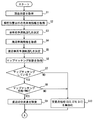
制御部13は、図5、図6に示す処理を周期的に実行する。ステップ(以下、ステップを省略)S1では、自車両2の現在位置を、GNSS受信部11から取得する。この現在位置は、緯度、経度、高度により表されている。S1の処理により、制御部13は自車両2の現在位置を決定できるので、S1は請求項の自車位置決定部に相当する。
[Processing executed by control unit 13]
The
S2では、現在位置以外の自車両情報を取得する。現在位置以外の自車両情報は、具体的には、自車両2の絶対方位、車速、ヨーレートを含んでおり、これらはそれぞれ、方位センサ20、車速センサ30、ヨーレートセンサ40から取得する。
In S2, own vehicle information other than the current position is acquired. The own vehicle information other than the current position specifically includes the absolute direction, the vehicle speed, and the yaw rate of the
S3では、自車両予測軌道PHを決定する。この自車両予測軌道PHは、自車両2の今後の走行軌道を予測したものである。本実施形態における自車両予測軌道PHは、S1で取得した現在位置を基点として、S2で取得した絶対方位の方向に延びる直線である。S2で取得した絶対方位の方向に延びる直線であることから、本実施形態における自車両予測軌道PHは、S2で取得した絶対方位を、自車両2の進行方向としている。このS3は請求項の自車両予測部に相当する。
In S3, determining the predicted vehicle trajectory P H. The predicted vehicle trajectory P H is obtained by predicting the future running track of the
S4では、周辺車両情報を、近距離無線通信部12から取得する。前述したように、自車両2は、自車両情報を、逐次、近距離無線通信部12から送信している。また、周辺車両3に搭載されている運転支援システム100は、自車両2に搭載されている運転支援システム1と同じ構成を備えている。したがって、周辺車両3に搭載されている運転支援システム100も、自車両情報と同じ種類の情報を逐次送信している。運転支援システム1にとっては、運転支援システム100が送信する情報は周辺車両情報となる。周辺車両3が自車両2の近距離無線通信部12の通信範囲内に存在していれば、近距離無線通信部12は、運転支援システム100が送信する周辺車両情報を受信できる。近距離無線通信部12が周辺車両情報を受信できた場合、S4で周辺車両情報を取得できる。この周辺車両情報は、周辺車両3の現在位置、絶対方位、車速、ヨーレートを含んでいる。また、周辺車両3の現在位置は、自車両2の現在位置と同様、航法信号に基づいて決定されている。
In S <b> 4, surrounding vehicle information is acquired from the short-range
S5では、周辺車両3の今後の走行軌道を予測した周辺車両予測軌道PRを決定する。本実施形態における周辺車両予測軌道PRは、S4で取得した現在位置を基点として、S4で取得した絶対方位の方向に延びる直線である。このS5が請求項の周辺車両予測部に相当し、周辺車両予測軌道PRの決定に用いているS4で取得した現在位置および絶対方位が請求項の軌道予測情報に相当する。
In S5, it determines the ambient predicted vehicle trajectory P R that predict future running track surrounding the
S6では、走行道路判定装置50からマップマッチング状態を取得し、取得したマップマッチング状態を、現在のマップマッチング状態に決定する。前述のように、マップマッチング状態は、マップマッチングの信頼度を表すので、このS6が請求項の信頼度決定部に相当する。
In S6, a map matching state is acquired from the traveling
なお、図1には、走行道路判定装置50が運転支援装置10に接続されている状態を示している。しかし、運転支援装置10は、走行道路判定装置50と接続されていなくても作動するようになっている。走行道路判定装置50が接続されていない場合、このS6を実行してもマップマッチング状態を取得することはできない。
FIG. 1 shows a state where the traveling
S7では、S6の処理結果に基づいて、自車両2がマップマッチングしているか否かを判断する。走行道路判定装置50から取得したマップマッチング状態がMM0である場合、および、マップマッチング状態を取得できなかった場合に、このS7の判断をNOとする。S7の判断がNOであれば、後述するS10に進む。
In S7, based on the processing result in S6, it is determined whether or not the
一方、走行道路判定装置50からMM1、MM2、MM3のいずれかを取得した場合には、このS7の判断をYESとする。S7の判断がYESであればS8に進む。
On the other hand, when any one of MM1, MM2, and MM3 is acquired from the traveling
S8では、マップマッチング状態がMM3であるか否かを判断する。この判断がNOである場合にはS10に進み、YESである場合にはS9に進む。 In S8, it is determined whether or not the map matching state is MM3. If this determination is NO, the process proceeds to S10, and if it is YES, the process proceeds to S9.
S9では、自車両2が走行する道路4において、自車両2の進行方向前方における直近の交差点を特定する。この処理は、具体的には、走行道路判定装置50から、当該交差点を表す交差点ノードAの情報を取得する処理である。このS9は請求項の交差点ノード決定部に相当する。
In S9, the nearest intersection in front of the traveling direction of the
S9を実行する場合、走行道路判定装置50は、マップマッチング状態をMM3としている。したがって、このS9で取得する交差点ノードAの情報は信頼性が高い。S9を実行した場合には、図5に示すS11に進む。
When executing S9, the traveling
一方、S7あるいはS8の判断がNOである場合には、S10を実行する。S10では、交差点処理を無効化する。この交差点処理は、交差点ノードAを用いた処理であり、具体的には、後述するS13、S16、S17である。S10を実行する場合には、S9を実行せずに図5に示すS11に進む。つまり、S10を実行した場合には、直近の交差点ノードAを取得せずにS11に進む。S10を実行した場合に、直近の交差点ノードAを取得しない理由は、S10を実行する場合には、マップマッチングの信頼性が低い、換言すれば、自車両2が走行している道路であるとしている道路が正しい可能性が高くはないからである。
On the other hand, if the determination in S7 or S8 is NO, S10 is executed. In S10, the intersection process is invalidated. This intersection process is a process using the intersection node A, and specifically, S13, S16, and S17 described later. When executing S10, the process proceeds to S11 shown in FIG. 5 without executing S9. That is, when S10 is executed, the process proceeds to S11 without acquiring the latest intersection node A. The reason why the nearest intersection node A is not acquired when S10 is executed is that the reliability of map matching is low when S10 is executed, in other words, the road on which the
S11では、S3で決定した自車両予測軌道PHと、S5で決定した周辺車両予測軌道PRに交点Xが存在するか否かを判断する。交点Xが存在しないと判断した場合には、S12に進む。S12では、運転支援を実行しないことに決定する。なお、運転支援を実行しない場合、後述するS18で説明する運転支援レベルを運転支援レベルlv1に決定していることになる。S12を実行したら、図5、図6に示す処理を終了する。一方、交点Xが存在すると判断した場合にはS13に進む。ただし、S10で交差点処理を無効化している場合には、S13をスキップしてS14に進む。 In S11, it is determined the predicted vehicle trajectory P H determined in S3, whether near the predicted vehicle trajectory P R at the intersection X determined in S5 is present. If it is determined that the intersection X does not exist, the process proceeds to S12. In S12, it is determined not to perform driving support. When driving support is not executed, the driving support level described in S18 described later is determined as the driving support level lv1. When S12 is executed, the processing shown in FIGS. 5 and 6 is terminated. On the other hand, if it is determined that the intersection point X exists, the process proceeds to S13. However, if the intersection process is invalidated in S10, S13 is skipped and the process proceeds to S14.
S13では、判定領域Bを設定する。このS13は請求項の領域設定部に相当する。本実施形態における判定領域Bは、図7に示すように、四角形であり、判定領域Bの中心を交点Xとし、自車両予測軌道PHに平行な一対の辺と、周辺車両予測軌道PRに平行な一対の辺とを備える。 In S13, the determination area B is set. This S13 corresponds to an area setting unit in the claims. Determination area B in the present embodiment, as shown in FIG. 7, a square, the center of the determination area B to the intersection X, and a pair of sides parallel to the predicted vehicle trajectory P H, nearby vehicle predicted trajectory P R And a pair of sides parallel to each other.
この判定領域Bは、次の方法で設定する。図7に示すように、まず、交点Xから自車両予測軌道PH上に長さLy1だけ離れた位置に点My1を配置する。次に、交点Xから自車両予測軌道PH上であって点My1とは反対方向に長さLy2だけ離れた位置に点My2を配置する。次に、交点Xから周辺車両予測軌道PR上に長さLx1だけ離れた位置に点Mx1を配置し、交点Xから周辺車両予測軌道PR上であって点Mx1とは反対方向に長さLx2だけ離れた位置に点Mx2を配置する。4辺の各辺が4つの点Mx1、Mx2、My1、My2のいずれかを通り、互いに平行な一対の辺のうちの一方が自車両予測軌道PHに平行、互いに平行な一対の辺のうちの他方が周辺車両予測軌道PRに平行な平行四辺形を判定領域Bとする。このようにして判定領域Bを設定する場合、図7に示す例のように、自車両予測軌道PHと周辺車両予測軌道PRとが直交していれば、判定領域Bは長方形になる。しかし、自車両予測軌道PHと周辺車両予測軌道PRとが直交しない場合には、判定領域Bは、4つの角が直角ではない平行四辺形になる。 This determination area B is set by the following method. As shown in FIG. 7, first, placing the position two points My1 apart by a length Ly1 from the intersection X on the estimated vehicle trajectory P H. Next, place the position two points My2 apart by a length Ly2 in a direction opposite to the predicted vehicle trajectory P H on an A to point My1 from the intersection X. Next, place the position two points Mx1 apart by a length Lx1 around the vehicle predicted orbit P R from the intersection X, the length in the opposite direction to the point Mx1 even on surrounding vehicles predicted trajectory P R from the intersection X A point Mx2 is arranged at a position separated by Lx2. Each side of four sides four points Mx1, Mx2, My1, My2 through one of parallel to one is predicted vehicle trajectory P H of the parallel pair of sides to each other, of the pair of parallel sides to one another the other is the determination area B a parallelogram parallel to the periphery of the vehicle predicted trajectory P R of. When setting the determination area B this way, as in the example shown in FIG. 7, if the predicted vehicle trajectory P H and the nearby vehicle predicted trajectory P R are orthogonal, the determination area B becomes rectangular. However, when the predicted vehicle trajectory P H and the peripheral vehicle predicted trajectory P R are not orthogonal, the determination region B will parallelogram four corners are not right angles.
長さLy1、Ly2、Lx1、Lx2は、個別にそれぞれ設定可能であり、各長さLy1、Ly2、Lx1、Lx2は予め設定されている。これらの長さLy1、Ly2、Lx1、Lx2により定まる判定領域Bの大きさは、交差点6の広さを大きくは超えないことが好ましい。判定領域Bは、判定領域B内に交差点ノードAがあるか否かを判断することにより、交点Xが交差点内であるか否かを判定するものだからである。
The lengths Ly1, Ly2, Lx1, and Lx2 can be individually set, and the lengths Ly1, Ly2, Lx1, and Lx2 are set in advance. It is preferable that the size of the determination area B determined by these lengths Ly1, Ly2, Lx1, and Lx2 does not greatly exceed the width of the
そこで、本実施形態では、判定領域Bにおいて周辺車両予測軌道PRに平行な一対の辺の長さが、車線はないが対面通行可能な道路の道路幅、あるいは、それよりも少し短い長さ、たとえば5−6mになるように、長さLx1、Lx2を設定している。また、本実施形態では、自車両予測軌道PHに平行な一対の辺の長さも、周辺車両予測軌道PRに平行な一対の辺の長さと同じになっている。 Therefore, in this embodiment, the determination nearby vehicle predicted trajectory P length of the pair of parallel sides to R in the area B, lane although not facing passable road road width or a little shorter than it For example, the lengths Lx1 and Lx2 are set so as to be 5-6 m. Further, in the present embodiment, the length of the predicted vehicle trajectory P H parallel pair of sides to also have the same as the length of the parallel pair of sides around the vehicle predicted trajectory P R.
続くS14では、自車両2が交点Xを通過するまでに要する通過所要時間と、周辺車両3が交点Xを通過するまでに要する通過所要時間とをそれぞれ算出する。自車両2の通過所要時間を算出するために、まず、自車両2の現在位置と交点Xの座標から、自車両2の現在位置から交点Xまでの距離を算出する。この距離を自車両2の現在の車速で割ることで、自車両2の通過所要時間を算出する。周辺車両3の通過所要時間も、自車両2の通過所要時間と同様にして算出する。そして、自車両2の通過所要時間と、周辺車両3の通過所要時間との時間差を算出する。このS14は請求項の時間差算出部に相当する。
In subsequent S14, the required travel time required for the
S15では、S14で算出した時間差が、予め設定した閾値以下であるか否かを判断する。この閾値は、自車両2と周辺車両3がともに交点Xを通過する場合に、衝突する危険性があることを判断するための値であり、閾値はたとえば数秒に設定される。S15の判断がNOであれば、前述したS12に進む。一方、S15の判断がYESであればS16へ進む。ただし、S10で交差点処理を無効化している場合にはS16、S17をスキップしてS18に進む。
In S15, it is determined whether or not the time difference calculated in S14 is equal to or less than a preset threshold value. This threshold value is a value for determining that there is a risk of collision when both the
S16は、請求項の判定部に相当しており、判定領域B内に、S9で特定した直近の交差点があるか否かを判断する。この判断がNOであればS17に進み、YESであればS17を実行することなくS18に進む。 S16 corresponds to a determination unit in the claims, and determines whether or not there is the nearest intersection specified in S9 in the determination region B. If this determination is NO, the process proceeds to S17, and if YES, the process proceeds to S18 without executing S17.
S17では、運転支援レベルを、S17を実行せずにS18に進んだ場合よりも抑制した運転支援レベルに決定する。本実施形態では、S17を実行せずにS18に進んだ場合よりも運転支援レベルを2段階低下させた運転支援レベルとする。運転支援レベルの内容は、S18の説明において述べる。S17で運転支援レベルを決定したらS18に進む。 In S17, the driving support level is determined to be a driving support level that is suppressed as compared with the case where the process proceeds to S18 without executing S17. In the present embodiment, the driving support level is set to a driving support level that is two steps lower than the case where the process proceeds to S18 without executing S17. The details of the driving support level will be described in the description of S18. When the driving support level is determined in S17, the process proceeds to S18.
S18では運転支援を実行する。このS18と、S17およびS12が請求項の運転支援部に相当する。本実施形態において実行する運転支援は、周辺車両3に衝突する可能性を表示装置60に表示するとともに、スピーカー70から、周辺車両3の存在を知らせる音を出力する支援である。運転支援レベルは複数のレベルが設定されている。
In S18, driving assistance is executed. S18, S17, and S12 correspond to the driving support unit in the claims. The driving assistance executed in the present embodiment is assistance for displaying the possibility of collision with the surrounding
ここでは、たとえば4段階の運転支援レベルが設定されているとする。最も高い運転支援レベルlv4では、警報を意味する画像を表示装置60に表示し、警報を意味する音をスピーカー70から出力する。運転支援レベルlv3では、注意を意味する画像を表示装置60に表示する。加えて、注意を意味する音をスピーカー70から出力してもよい。運転支援レベルlv2では、周辺車両3を検知したことを意味する画像を表示装置60に表示する。運転支援レベルlv1では、何も運転支援を行わない。なお、運転支援レベルのレベル数および各運転支援レベルで実行する運転支援の内容は、上述の内容に限られない。
Here, for example, it is assumed that four levels of driving support levels are set. At the highest driving support level lv4, an image indicating an alarm is displayed on the
S17を実行せずにS18に進んだ場合には、上述の運転支援レベルlv4または運転支援レベルlv3のいずれかを実行する。運転支援レベルlv4または運転支援レベルlv3のいずれを実行するかは、自車両2の運転者が最大量の踏み込み量でブレーキを踏んだ場合に、自車両2が交点Xの手前で停止できるか否かにより決定する。自車両2の運転者が最大量の踏み込み量でブレーキを踏んでも、自車両2が交点Xの手前で停止できない場合には運転支援レベルlv4を実行し、自車両2が交点Xの手前で停止できる場合には運転支援レベルlv3を実行する。
When the process proceeds to S18 without executing S17, either the driving support level lv4 or the driving support level lv3 described above is executed. Whether the driving support level lv4 or the driving support level lv3 is executed depends on whether or not the
なお、自車両2の運転者が最大量の踏み込み量でブレーキを踏んだ場合における、自車両2の走行距離と速度低下の関係を表す計算式が予め設定されている。その計算式を用いて、自車両2の運転者が最大量の踏み込み量でブレーキを踏んだ場合に、自車両2が交点Xの手前で停止できるか否かを決定する。
A calculation formula is set in advance that represents the relationship between the travel distance of the
前述したように、S17では、S17を実行せずにS18に進んだ場合よりも、運転支援レベルを2段階低下させる。したがって、S17を実行した後にS18を実行する場合には、運転支援レベルlv2または運転支援レベルlv1で運転支援を実行する。なお、運転支援レベルを運転支援レベルlv1に決定した場合には、運転支援を行わないことになる。 As described above, in S17, the driving support level is lowered by two steps as compared with the case where the process proceeds to S18 without executing S17. Therefore, when executing S18 after executing S17, the driving support is executed at the driving support level lv2 or the driving support level lv1. Note that when the driving support level is determined to be the driving support level lv1, the driving support is not performed.
S17を実行するのはS16の判断がNOになった場合であるので、S17を実行する場合、交差点ノードAは判定領域B内にない。したがって、交点Xは交差点内ではない可能性が高い。車両同士の衝突が発生する場所は通常、交差点内であることから、S17を実行する場合には、S15で時間差が閾値以下と判断しても、自車両2と周辺車両3は衝突する可能性は低いと考えられる。そこで、S17では、運転支援レベルを、S17を実行せずにS18を実行する場合よりも抑制した運転支援レベルに決定するのである。
Since S17 is executed when the determination in S16 is NO, the intersection node A is not in the determination area B when S17 is executed. Therefore, there is a high possibility that the intersection X is not within the intersection. Since the place where the collision between the vehicles occurs is usually in the intersection, even if it is determined that the time difference is equal to or less than the threshold value in S15, the
ただし、S16、S17の処理を実行して運転支援レベルを抑制してよいのは、直近の交差点ノードAを正しく自車両2が走行している道路上の交差点に特定できている場合に限られる。そこで、本実施形態では、マップマッチング状態がMM3でない場合には、S16、S17の処理をスキップするようにしている。また、S16の処理をスキップするので、合わせてS16の処理で用いる判定領域Bを設定する処理であるS13もスキップしている。S16、S17の処理をスキップすることにより、実際には交点Xが交差点内であるにも関わらず、運転支援レベルを低下させてしまうことを抑制できる。
However, the process of S16 and S17 may be executed to suppress the driving support level only when the nearest intersection node A can be correctly identified as an intersection on the road on which the
[運転支援を抑制する具体例]
次に、S17を実行して運転支援を抑制する具体例を説明する。たとえば、図8に示すように、自車両2が走行する道路4に対して立体交差する道路7を周辺車両3が走行している場合、自車両2と周辺車両3は衝突する可能性はない。図8に示すように、判定領域B内には、交差点ノードAは存在していない。したがって、自車両予測軌道PHと周辺車両予測軌道PRとの交点Xが存在し、かつ、自車両2の通過所要時間と周辺車両3の通過所要時間との時間差が閾値以下であっても、S16の判断がNOになることにより、運転支援が抑制される。
[Specific examples of suppressing driving support]
Next, a specific example in which the driving support is suppressed by executing S17 will be described. For example, as shown in FIG. 8, when the surrounding
また、図9に示すように、自車両2が走行する道路4の周辺を通るものの、道路4とは交差しない道路8を周辺車両3が走行している場合にも、判定領域B内に交差点ノードAが存在しない場合が多いので、不要な運転支援が抑制される。
Further, as shown in FIG. 9, even when the surrounding
[運転支援を抑制しない具体例]
次に、図8、図9とは反対に、運転支援を抑制しない具体例を説明する。図10に示すように、道路114と道路115が交差点116で交差しており、自車両2が交差点116に向かって道路114を走行しており、周辺車両3が交差点116に向かって道路115を走行しているとする。また、自車両2のマップマッチング状態はMM3であるとする。この状況では、S9において、交差点ノードA3が、直近の交差点として特定される。
[Specific examples that do not suppress driving support]
Next, on the contrary to FIGS. 8 and 9, a specific example in which driving assistance is not suppressed will be described. As shown in FIG. 10, the
その後、自車両2が交差点116内に入り、自車両2の位置が図11に示す位置になったとする。この場合、マップマッチング状態はMM1あるいはMM2になる。マップマッチング状態がMM1になる可能性がある理由は、自車両2の現在の進行方向が、道路114にも、道路115にも沿っていないからである。マップマッチング状態がMM2になる可能性がある理由は、自車両2の位置が実際には図11に示す位置であっても、マップマッチングにより、自車両2の位置が、図11に示すリンクLk1あるいはLk2上に補正される可能性があるからである。マップマッチング状態がMM1あるいはMM2になるので、S10の処理に進み、S13、S16、S17を無効化する。
Thereafter, it is assumed that the
仮に、この処理を行わないで、マップマッチング状態がMM2であってもS9の処理を実行するとした場合を考える。この場合、そのS9において、実際に自車両2が位置している交差点116を表す交差点ノードA3ではなく、交差点ノードA4あるいはA5を、直近の交差点を表す交差点ノードAとして特定してしまう可能性がある。そうなると、S16において、交点Xを中心として設定する判定領域B内に、直近の交差点ノードAとして特定した交差点ノードA5あるいはA4が存在しないと判断して、S17を実行して運転支援を抑制してしまう。
Suppose that this process is not performed and the process of S9 is executed even if the map matching state is MM2. In this case, in S9, there is a possibility that the intersection node A4 or A5 is identified as the intersection node A representing the nearest intersection, not the intersection node A3 representing the
しかし、本実施形態では、マップマッチング状態がMM2やMM1である場合には、S13、S16、S17を無効化することで、判定領域B内に直近の交差点ノードAがあるいは否かを判断しない。したがって、図11に示している状態であるにも関わらず、判定領域B内に直近の交差点ノードAがないと判断して、運転支援レベルを低下させてしまうことが抑制される。 However, in this embodiment, when the map matching state is MM2 or MM1, it is not determined whether or not the nearest intersection node A is in the determination area B by invalidating S13, S16, and S17. Therefore, in spite of the state shown in FIG. 11, it is determined that there is no nearest intersection node A in the determination area B, and the driving support level is reduced.
図11に示す状態から、自車両2がさらに走行して、図12に示すように、自車両2の位置が交差点116を出ると、再びマップマッチング状態がMM3になる。したがって、図12の状態では、直近の交差点を表す交差点ノードAが交差点ノードA4になる。よって、S16の判断がYESになるので、運転支援は抑制されない。
When the
[第1実施形態のまとめ]
以上、説明した本実施形態では、マップマッチング状態がMM3である場合には、S9を実行して、マップマッチングにより決定した自車両2の現在位置が位置する道路上における直近交差点の交差点ノードAを特定する。そして、この交差点ノードAが判定領域B内にあるか否かを判定している。
[Summary of First Embodiment]
In the present embodiment described above, when the map matching state is MM3, S9 is executed, and the intersection node A of the nearest intersection on the road where the current position of the
判定領域Bは、自車両予測軌道PHと周辺車両予測軌道PRに交点Xがある場合に、その交点Xを含むように設定する領域であるので、判定領域B内に交差点ノードAがある場合、自車両2と周辺車両3は同じ交差点を通過することが予想される。一方、判定領域B内に交差点ノードAがない場合、自車両2と周辺車両3は同じ交差点を通過しないことが予想される。
Determining region B, if there is a predicted vehicle trajectory P H and the peripheral vehicle predicted trajectory P R at the intersection X, since the region to be set to include the intersection X, there is an intersection node A in the determination area B In this case, the
車両同士の衝突は、通常、交差点で生じる。換言すれば、自車両予測軌道PHと周辺車両予測軌道PRとが交わる交点Xがあっても、その交点Xが交差点でない場合には、自車両2と周辺車両3とが衝突する可能性は低いと考えられる。つまり、判定領域B内に交差点ノードAがあるか否かを判定することは、自車両2と周辺車両3との衝突可能性が高いか否かを判定していることになる。
A collision between vehicles usually occurs at an intersection. In other words, even predicted vehicle trajectory P H and the peripheral vehicle predicted trajectory P R and intersects the intersection point X is, when the intersection X is not an intersection is possible that the
判定領域B内に交差点ノードAがない場合、交点Xが交差点内でない可能性が高く、交点Xが交差点内でない場合には、自車両2と周辺車両3とが衝突する可能性は低いと考えられる。そこで、判定領域B内に交差点ノードAがない場合、S17を実行して、判定領域B内に交差点ノードAがある場合よりも、運転支援レベルを運転支援が抑制されるレベルとする。
If there is no intersection node A in the determination area B, the possibility that the intersection X is not in the intersection is high, and if the intersection X is not in the intersection, the possibility that the
したがって、本実施形態では、マップマッチング状態がMM3である場合には、道路地図情報を活用して運転支援を抑制するか否かを判定する。これにより、不要な運転支援が行われてしまうことを抑制できる。 Therefore, in this embodiment, when the map matching state is MM3, it is determined whether or not the driving support is suppressed using the road map information. Thereby, it can suppress that unnecessary driving assistance is performed.
一方、マップマッチング状態がMM0、MM1、MM2である場合には、S13、S16、S17を無効化する。これにより、マップマッチング状態がMM0、MM1、MM2である場合には、道路地図情報を用いて運転支援を抑制するか否かを判定しない。そして、自車両予測軌道PHと周辺車両予測軌道PRに交点Xがあるか否かに基づいて運転支援を実行するか否かを決定する。これにより、運転支援が必要な状況であるのに運転支援が行われないことも抑制される。 On the other hand, when the map matching state is MM0, MM1, or MM2, S13, S16, and S17 are invalidated. Thereby, when the map matching state is MM0, MM1, MM2, it is not determined whether or not the driving support is suppressed using the road map information. Then, to determine whether to perform driving support based on whether there is a predicted vehicle trajectory P H and the peripheral vehicle predicted trajectory P R at the intersection X. Thereby, it is suppressed that driving assistance is not performed although driving assistance is required.
以上、本発明の実施形態を説明したが、本発明は上述の実施形態に限定されるものではなく、次の変形例も本発明の技術的範囲に含まれ、さらに、下記以外にも要旨を逸脱しない範囲内で種々変更して実施できる。 As mentioned above, although embodiment of this invention was described, this invention is not limited to the above-mentioned embodiment, The following modification is also contained in the technical scope of this invention, Furthermore, the summary other than the following is also included. Various modifications can be made without departing from the scope.
<変形例1>
前述の実施形態では判定領域Bは四角形であったが、判定領域Bは、他の形状、たとえば、円形でもよい。
<
In the above-described embodiment, the determination region B is a quadrangle, but the determination region B may have another shape, for example, a circle.
<変形例2>
前述の実施形態では、S3において、自車両2が向いている絶対方位を表す直線を自車両2の進行方向として、自車両予測軌道PHを決定していた。しかし、自車両2が進行する方向として、自車両2の旋回半径Rの円弧であって、自車両2の現在位置を基点とし、自車両2において自車両2の前後方向線に接する円弧を用いてもよい。なお、自車両2の前後方向線は、自車両2の絶対方位を表す線である。また、自車両2の旋回半径Rは、車速をヨーレートで割ることで算出できる。
<
In the above-described embodiment, in S < b> 3, the host vehicle predicted trajectory PH is determined with the straight line representing the absolute azimuth toward which the
<変形例3>
自車両2の場合と同様、周辺車両3についても、S5において、周辺車両3が進行する方向として、周辺車両3の旋回半径Rの円弧であって、周辺車両3の現在位置を基点とし、周辺車両3において周辺車両3の前後方向線に接する円弧を用いてもよい。なお、この変形例3では、周辺車両情報に含まれているヨーレートを使用して周辺車両予測軌道PRを決定することになる。この変形例3とは異なり、前述の実施形態においてはヨーレートを用いずに周辺車両予測軌道PRを決定している。したがって、前述の実施形態においては、周辺車両情報にヨーレートが含まれていなくてもよい。
<
As in the case of the
<変形例4>
前述の実施形態では、判定領域Bの各辺の長さLy1、Ly2、Lx1、Lx2は予め設定されていた。しかし、判定領域Bの辺の長さLx1、Lx2を、自車両2が走行する道路の道路幅あるいは車線数に応じて決定してもよいし、判定領域Bの辺の長さLy1、Ly2を、周辺車両3が走行する道路の道路幅あるいは車線数に応じて決定してもよい。なお、道路幅、車線数は、リンク情報に含まれている。
<Modification 4>
In the above-described embodiment, the lengths Ly1, Ly2, Lx1, and Lx2 of each side of the determination region B are set in advance. However, the side lengths Lx1 and Lx2 of the determination region B may be determined according to the road width or the number of lanes of the road on which the
<変形例5>
方位センサ20に代えて、逐次検出する自車両2の現在位置の変化から、自車両2の進行方位を決定してもよい。また、逐次検出する自車両2の現在位置の変化から、自車両2のヨーレートを算出してもよい。
<
Instead of the
周辺車両3についても同様に、逐次検出する周辺車両3の現在位置の変化から、周辺車両3の進行方位を決定してもよいし、逐次検出する周辺車両3の現在位置の変化から、周辺車両3のヨーレートを算出してもよい。
Similarly, for the surrounding
<変形例6>
通過所要時間の算出に加速度を用いてもよい。すなわち、自車両2の速度に加えて加速度を取得し、自車両2の加速度から自車両2の速度変化を予測して、自車両2が交点Xを通過する通過所要時間を決定する。また、周辺車両3の速度に加えて加速度を取得し、周辺車両3の加速度から周辺車両3の速度変化を予測して、周辺車両3が交点Xを通過する通過所要時間を決定する。このようにすれば、より精度よく、自車両2の通過所要時間と周辺車両3の通過所要時間を算出できる。
<
Acceleration may be used for calculating the time required for passing. That is, the acceleration is acquired in addition to the speed of the
<変形例7>
前述の実施形態では、判定領域B内に、直近の交差点の交差点ノードAがあるか否かを判断していたが、直近の交差点だけでなく、直近の交差点の一つ後に自車両2が通過する交差点についての交差点ノードAがあるか否かも判断してもよい。
<
In the above-described embodiment, it is determined whether or not there is an intersection node A of the nearest intersection in the determination area B. However, not only the nearest intersection but also the
<変形例8>
前述の実施形態では、周辺車両3が送信した現在位置および絶対方位を用いて、自車両2が周辺車両予測軌道PRを決定していたが、周辺車両3が周辺車両予測軌道PRを逐次算出して送信してもよい。この場合には、周辺車両3が送信する周辺車両予測軌道PRが請求項の軌道予測情報に相当する。
<
In the foregoing embodiment, by using the current position and the absolute direction in which the
<変形例9>
前述の実施形態では、S16の判断がNOになり、S17を実行して運転支援レベルを低下させると、実質的には、S15の判断がNOである場合に実行するS12と同様、運転支援を実行しないことになる。
<Modification 9>
In the above-described embodiment, when the determination of S16 is NO and the driving support level is lowered by executing S17, the driving support is substantially performed in the same manner as S12 executed when the determination of S15 is NO. Do not execute.
そこで、図13に示すように、S14、S15を実行する前に、S16を実行してもよい。そして、S16の判断がNOである場合にはS12に進み、NOである場合にS14、S15へ進むようにしてもよい。この変形例9は、判定領域B内に交差点ノードAがないと判断した場合に、時間差を用いずに、運転支援レベルを、最も運転支援が抑制されたレベルに決定していることになる。この変形例9によれば、判定領域B内に交差点ノードAがないと判断した場合には、通過所要時間および時間差を算出する必要がないので、演算負荷が軽減する。 Therefore, as shown in FIG. 13, S16 may be executed before executing S14 and S15. If the determination in S16 is NO, the process proceeds to S12. If the determination is NO, the process may proceed to S14 and S15. In this modified example 9, when it is determined that there is no intersection node A in the determination region B, the driving support level is determined to be the level at which driving support is most suppressed without using a time difference. According to this modified example 9, when it is determined that there is no intersection node A in the determination region B, it is not necessary to calculate the required travel time and the time difference, so the calculation load is reduced.
<変形例10>
また、前述の実施形態において、S14、S15の処理をなしにしてもよい。
<
In the above-described embodiment, the processes of S14 and S15 may be omitted.
<変形例11>
周辺車両3が備えている運転支援システム100は、前述した周辺車両情報を送信すればよい。したがって、運転支援システム100は、走行道路判定装置50を備えていなくてもよい。
<
The driving
<変形例12>
前述の実施形態では、走行道路判定装置50が、マップマッチングを実施して自車両2が走行する道路を特定していた。しかし、運転支援装置10が、自車両2の現在位置に基づいて定まる自車両付近の道路地図情報を走行道路判定装置50から取得し、制御部13がマップマッチングを行ってもよい。また、運転支援装置10が道路地図情報を備えるようにすれば、道路地図情報を走行道路判定装置50から取得しなくてもよい。
<
In the above-described embodiment, the traveling
<変形例13>
前述の実施形態では、近距離無線通信部12を備えて、この近距離無線通信部12により、車車間通信を行っていた。しかし、近距離無線通信部12に加えて、あるいは、近距離無線通信部12に代えて、広域無線通信部を車車間通信部として備えていてもよい。
<
In the above-described embodiment, the short-range
<変形例14>
前述の実施形態では、自車両予測軌道PHを決定するために用いる自車両2の現在位置は、GNSS受信部11が算出した現在位置としていた。しかし、自車両予測軌道PHを決定するために用いる自車両2の現在位置は、マップマッチング状態がMM3であれば、マップマッチング後の現在位置としてもよい。
<Modification 14>
In the above embodiments, the current position of the
1:運転支援システム 2:自車両 3:周辺車両 4:道路 5:道路 6:交差点 7:道路 8:道路 10:運転支援装置 11:GNSS受信部 12:近距離無線通信部 13:制御部 20:方位センサ 30:車速センサ 40:ヨーレートセンサ 50:走行道路判定装置 51:記憶部 60:表示装置 70:スピーカー 100:運転支援システム 104:道路 105:道路 106:交差点 114:道路 115:道路 116:交差点 A:交差点ノード B:判定領域 PH:自車両予測軌道 PR:周辺車両予測軌道 X:交点 1: driving support system 2: own vehicle 3: surrounding vehicle 4: road 5: road 6: intersection 7: road 8: road 10: driving support device 11: GNSS receiving unit 12: short-range wireless communication unit 13: control unit 20 : Direction sensor 30: Vehicle speed sensor 40: Yaw rate sensor 50: Traveling road determination device 51: Storage unit 60: Display device 70: Speaker 100: Driving support system 104: Road 105: Road 106: Intersection 114: Road 115: Road 116: intersection A: intersection node B: determination area P H: the estimated vehicle trajectory P R: near the predicted vehicle trajectory X: intersection
Claims (7)
衛星航法システムが備える航法衛星が送信する航法信号を受信して決定した位置を逐次取得して、前記運転支援装置が用いられている前記車両である自車両の現在位置を逐次決定する自車位置決定部(S1)と、
前記自車両の現在位置の軌跡と道路形状との比較に基づいて前記自車両の現在位置を道路上に補正するマップマッチングの信頼度を逐次決定する信頼度決定部(S6)と、
前記自車両の現在位置と前記自車両の進行方位とから、前記自車両の今後の走行軌道である自車両予測軌道を予測する自車両予測部(S3)と、
前記自車両の周辺に存在している周辺車両の現在位置と前記周辺車両の進行方位とから予測される前記周辺車両の今後の走行軌道である周辺車両予測軌道を予測するための軌道予測情報を、前記自車両に備えられている車車間通信部から取得して、前記周辺車両の今後の走行軌道である周辺車両予測軌道を予測する周辺車両予測部(S5)と、
前記自車両予測軌道と前記周辺車両予測軌道に交点がある場合に、前記交点を含むように判定領域を設定する領域設定部(S13)と、
前記信頼度決定部が決定した前記マップマッチングの信頼度が、予め設定された高信頼度であることに基づいて、交差点を交差点ノードで表している道路地図情報から、前記マップマッチングにより決定した前記自車両の現在位置が位置する道路において、前記自車両の進行方向に存在する交差点ノードを決定する交差点ノード決定部(S9)と、
前記領域設定部が設定した前記判定領域内に、前記交差点ノード決定部が決定した前記交差点ノードがあるか否かを判定する判定部(S16)とを備え、
前記運転支援部は、
前記判定領域内に前記交差点ノードがない場合、前記判定領域内に前記交差点ノードがある場合よりも、運転支援レベルを運転支援が抑制されるレベルとし、
前記信頼度決定部が決定した前記マップマッチングの信頼度が、予め設定された低信頼度である場合、前記判定部による判定を行うことなく、前記自車位置決定部が決定した前記自車両の現在位置と前記自車両の進行方位とから前記自車両予測部が予測した前記自車両予測軌道と、前記周辺車両予測軌道に交点があるか否かに基づいて前記運転支援を実行するか否かを決定する運転支援装置。 A driving support device including a driving support unit (S12, S17, S18) that is used in a vehicle and performs control for supporting driving of the driver of the vehicle,
The own vehicle position for sequentially acquiring the position determined by receiving the navigation signal transmitted by the navigation satellite provided in the satellite navigation system and sequentially determining the current position of the own vehicle that is the vehicle in which the driving support device is used. A determination unit (S1);
A reliability determination unit (S6) for sequentially determining the reliability of map matching for correcting the current position of the host vehicle on the road based on a comparison between the locus of the current position of the host vehicle and a road shape;
A host vehicle prediction unit (S3) that predicts a host vehicle predicted track that is a future track of the host vehicle from a current position of the host vehicle and a traveling direction of the host vehicle;
Trajectory prediction information for predicting a surrounding vehicle predicted track that is a future traveling track of the surrounding vehicle predicted from a current position of the surrounding vehicle existing around the host vehicle and a traveling direction of the surrounding vehicle. A surrounding vehicle prediction unit (S5) that obtains from a vehicle-to-vehicle communication unit provided in the host vehicle and predicts a surrounding vehicle predicted track that is a future traveling track of the surrounding vehicle;
An area setting unit (S13) for setting a determination area so as to include the intersection when there is an intersection between the own vehicle predicted trajectory and the surrounding vehicle predicted trajectory;
Based on the reliability of the map matching determined by the reliability determination unit being a high reliability set in advance, the road map information representing an intersection by an intersection node is determined by the map matching. An intersection node determination unit (S9) for determining an intersection node existing in the traveling direction of the host vehicle on the road where the current position of the host vehicle is located;
A determination unit (S16) for determining whether or not the intersection node determined by the intersection node determination unit is within the determination region set by the region setting unit;
The driving support unit
When there is no intersection node in the determination region, the driving support level is a level at which driving support is suppressed, compared to the case where the intersection node is in the determination region,
When the reliability of the map matching determined by the reliability determination unit is a low reliability set in advance, the vehicle position determination unit determined by the vehicle position determination unit without performing determination by the determination unit Whether or not to execute the driving support based on whether or not there is an intersection between the predicted vehicle trajectory predicted by the host vehicle prediction unit from the current position and the traveling direction of the host vehicle and the predicted predicted vehicle track Driving assistance device to determine.
前記交点に前記自車両が到達するまでの時間と、前記交点に前記周辺車両が到達するまでの時間との時間差を算出する時間差算出部(S14)を備え、
前記運転支援部は、前記交点があるか否かと、前記判定部による判定結果と、前記マップマッチングの信頼度とに加えて、前記時間差算出部が算出した前記時間差に基づいて、前記運転支援のレベルを決定する運転支援装置。 In claim 1,
A time difference calculation unit (S14) that calculates a time difference between the time until the host vehicle reaches the intersection and the time until the surrounding vehicle reaches the intersection;
The driving support unit determines whether or not the driving support is based on the time difference calculated by the time difference calculating unit in addition to whether or not there is the intersection, the determination result by the determination unit, and the reliability of the map matching. Driving assistance device that determines the level.
前記運転支援部は、前記判定部が前記判定領域内に前記交差点ノードがないと判断した場合に、前記時間差を用いずに、運転支援レベルを運転支援が抑制されるレベルとする運転支援装置。 In claim 2,
The said driving assistance part is a driving assistance apparatus which makes a driving assistance level a level by which driving assistance is suppressed, without using the said time difference, when the said determination part judges that the said intersection node is not in the said determination area | region.
前記マップマッチングの状態には、前記自車両の現在位置を一つの道路上に確定できている確定状態と、前記自車両が位置する道路の候補として複数の道路が存在している複数候補状態があり、
前記信頼度決定部は、前記マップマッチングの状態が前記確定状態であれば、前記マップマッチングの信頼度を前記高信頼度とし、前記マップマッチングの状態が前記複数候補状態であれば、前記マップマッチングの信頼度を低信頼度とする運転支援装置。 In any one of Claims 1-3,
The map matching state includes a confirmed state in which the current position of the host vehicle can be confirmed on one road, and a plurality of candidate states in which a plurality of roads exist as candidates for the road on which the host vehicle is located. Yes,
The reliability determination unit determines the reliability of the map matching as the high reliability if the state of the map matching is the final state, and the map matching if the state of the map matching is the multiple candidate state. Driving support system that makes the reliability of the vehicle low.
前記マップマッチングの状態には、前記自車両の現在位置を一つの道路上に確定できている確定状態と、前記自車両の現在位置を道路上に確定できていない未確定状態と、前記確定状態から前記未確定状態への移行過程である移行状態とがあり、
前記信頼度決定部は、前記マップマッチングの状態が前記確定状態であれば、前記マップマッチングの信頼度を前記高信頼度とし、前記マップマッチングの状態が前記未確定状態または前記移行状態であれば、前記マップマッチングの信頼度を低信頼度とする運転支援装置。 In any one of Claims 1-3,
The map matching state includes a confirmed state in which the current position of the own vehicle can be confirmed on one road, an unconfirmed state in which the current position of the own vehicle cannot be confirmed on the road, and the confirmed state. And a transition state that is a transition process from the indeterminate state to
The reliability determination unit sets the reliability of the map matching as the high reliability if the state of the map matching is the determined state, and if the state of the map matching is the indeterminate state or the transition state A driving support device that makes the reliability of the map matching low.
前記運転支援部は、前記信頼度決定部が前記マップマッチングの信頼度を決定できていない場合に前記マップマッチングの信頼度を低信頼度とする運転支援装置。 In any one of Claims 1-5,
The driving support device is a driving support device in which the reliability of the map matching is set to a low reliability when the reliability determination unit cannot determine the reliability of the map matching.
前記交差点ノード決定部は、前記自車両の進行方向において直近に存在する前記交差点ノードを決定する運転支援装置。 In any one of Claims 1-6,
The said intersection node determination part is a driving assistance device which determines the said intersection node which exists immediately in the advancing direction of the said own vehicle.
Priority Applications (2)
| Application Number | Priority Date | Filing Date | Title |
|---|---|---|---|
| JP2016005473A JP6520728B2 (en) | 2016-01-14 | 2016-01-14 | Driving support device |
| US15/401,141 US10269247B2 (en) | 2016-01-14 | 2017-01-09 | Drive support apparatus |
Applications Claiming Priority (1)
| Application Number | Priority Date | Filing Date | Title |
|---|---|---|---|
| JP2016005473A JP6520728B2 (en) | 2016-01-14 | 2016-01-14 | Driving support device |
Publications (2)
| Publication Number | Publication Date |
|---|---|
| JP2017126219A true JP2017126219A (en) | 2017-07-20 |
| JP6520728B2 JP6520728B2 (en) | 2019-05-29 |
Family
ID=59314864
Family Applications (1)
| Application Number | Title | Priority Date | Filing Date |
|---|---|---|---|
| JP2016005473A Active JP6520728B2 (en) | 2016-01-14 | 2016-01-14 | Driving support device |
Country Status (2)
| Country | Link |
|---|---|
| US (1) | US10269247B2 (en) |
| JP (1) | JP6520728B2 (en) |
Cited By (7)
| Publication number | Priority date | Publication date | Assignee | Title |
|---|---|---|---|---|
| KR20190078824A (en) * | 2017-12-27 | 2019-07-05 | 현대자동차주식회사 | Vehicle and controlling method thereof |
| JP2020039115A (en) * | 2018-08-31 | 2020-03-12 | バイドゥ オンライン ネットワーク テクノロジー (ベイジン) カンパニー リミテッド | Method, equipment and device for transmitting data of intelligent driving car |
| JP2020106979A (en) * | 2018-12-26 | 2020-07-09 | 株式会社ゼンリンデータコム | Information processing device, information processing method, and program |
| JP2020106338A (en) * | 2018-12-26 | 2020-07-09 | 株式会社ゼンリンデータコム | Information processing device, information processing method, and program |
| WO2020255296A1 (en) | 2019-06-19 | 2020-12-24 | 三菱電機株式会社 | Relative position determining device, relative position determining method, and relative position determining program |
| WO2022137819A1 (en) * | 2020-12-24 | 2022-06-30 | 本田技研工業株式会社 | Vehicle |
| JP2022534517A (en) * | 2019-06-04 | 2022-08-01 | 日立Astemo株式会社 | Vehicle cruise control device, vehicle cruise control method and computer program product |
Families Citing this family (3)
| Publication number | Priority date | Publication date | Assignee | Title |
|---|---|---|---|---|
| US10289115B2 (en) * | 2017-06-01 | 2019-05-14 | Aptiv Technologies Limited | Automated vehicle map localization based on observed geometries of roadways |
| KR102323394B1 (en) * | 2018-01-22 | 2021-11-08 | 삼성전자주식회사 | Apparatus and method for assisting driving of a vehicle |
| FR3120690B1 (en) * | 2021-03-15 | 2023-02-10 | Psa Automobiles Sa | Method and device for determining the reliability of a base definition cartography. |
Citations (3)
| Publication number | Priority date | Publication date | Assignee | Title |
|---|---|---|---|---|
| JP2008097413A (en) * | 2006-10-13 | 2008-04-24 | Mitsubishi Electric Corp | In-vehicle system for providing safety support information |
| JP2010250616A (en) * | 2009-04-16 | 2010-11-04 | Toyota Motor Corp | Driving support device |
| JP2014157395A (en) * | 2013-02-14 | 2014-08-28 | Denso Corp | Vehicle driving support system and driving support method |
Family Cites Families (4)
| Publication number | Priority date | Publication date | Assignee | Title |
|---|---|---|---|---|
| JP3501009B2 (en) | 1999-03-26 | 2004-02-23 | トヨタ自動車株式会社 | Vehicle collision avoidance control device |
| US6445308B1 (en) | 1999-01-12 | 2002-09-03 | Toyota Jidosha Kabushiki Kaisha | Positional data utilizing inter-vehicle communication method and traveling control apparatus |
| JP2006182207A (en) | 2004-12-28 | 2006-07-13 | Masahiro Watanabe | Operation assistance system |
| JP2013134567A (en) | 2011-12-26 | 2013-07-08 | Suzuki Motor Corp | Driving support device |
-
2016
- 2016-01-14 JP JP2016005473A patent/JP6520728B2/en active Active
-
2017
- 2017-01-09 US US15/401,141 patent/US10269247B2/en active Active
Patent Citations (3)
| Publication number | Priority date | Publication date | Assignee | Title |
|---|---|---|---|---|
| JP2008097413A (en) * | 2006-10-13 | 2008-04-24 | Mitsubishi Electric Corp | In-vehicle system for providing safety support information |
| JP2010250616A (en) * | 2009-04-16 | 2010-11-04 | Toyota Motor Corp | Driving support device |
| JP2014157395A (en) * | 2013-02-14 | 2014-08-28 | Denso Corp | Vehicle driving support system and driving support method |
Cited By (15)
| Publication number | Priority date | Publication date | Assignee | Title |
|---|---|---|---|---|
| KR20190078824A (en) * | 2017-12-27 | 2019-07-05 | 현대자동차주식회사 | Vehicle and controlling method thereof |
| KR102464607B1 (en) | 2017-12-27 | 2022-11-08 | 현대자동차주식회사 | Vehicle and controlling method thereof |
| JP2020039115A (en) * | 2018-08-31 | 2020-03-12 | バイドゥ オンライン ネットワーク テクノロジー (ベイジン) カンパニー リミテッド | Method, equipment and device for transmitting data of intelligent driving car |
| US11374688B2 (en) | 2018-08-31 | 2022-06-28 | Apollo Intelligent Driving Technology (Beijing) Co., Ltd. | Data transmission method and device for intelligent driving vehicle, and device |
| JP7046452B2 (en) | 2018-12-26 | 2022-04-04 | 株式会社ゼンリンデータコム | Information processing equipment, information processing methods and programs |
| JP7049242B2 (en) | 2018-12-26 | 2022-04-06 | 株式会社ゼンリンデータコム | Information processing equipment, information processing methods and programs |
| JP2020106338A (en) * | 2018-12-26 | 2020-07-09 | 株式会社ゼンリンデータコム | Information processing device, information processing method, and program |
| JP2020106979A (en) * | 2018-12-26 | 2020-07-09 | 株式会社ゼンリンデータコム | Information processing device, information processing method, and program |
| JP2022534517A (en) * | 2019-06-04 | 2022-08-01 | 日立Astemo株式会社 | Vehicle cruise control device, vehicle cruise control method and computer program product |
| CN113994406A (en) * | 2019-06-19 | 2022-01-28 | 三菱电机株式会社 | Relative position determination device, relative position determination method, and relative position determination program |
| WO2020255296A1 (en) | 2019-06-19 | 2020-12-24 | 三菱電機株式会社 | Relative position determining device, relative position determining method, and relative position determining program |
| CN113994406B (en) * | 2019-06-19 | 2023-09-08 | 三菱电机株式会社 | Relative position determination device, relative position determination method, and storage medium |
| US11915494B2 (en) | 2019-06-19 | 2024-02-27 | Mitsubishi Electric Corporation | Relative position determining apparatus, relative position determining method, and non-transitory computer readable recording medium |
| WO2022137819A1 (en) * | 2020-12-24 | 2022-06-30 | 本田技研工業株式会社 | Vehicle |
| JP7413572B2 (en) | 2020-12-24 | 2024-01-15 | 本田技研工業株式会社 | vehicle |
Also Published As
| Publication number | Publication date |
|---|---|
| US20170206787A1 (en) | 2017-07-20 |
| US10269247B2 (en) | 2019-04-23 |
| JP6520728B2 (en) | 2019-05-29 |
Similar Documents
| Publication | Publication Date | Title |
|---|---|---|
| JP6520728B2 (en) | Driving support device | |
| JP6468171B2 (en) | Driving assistance device | |
| JP6607155B2 (en) | Driving assistance device | |
| JP5472163B2 (en) | Speed regulation value notification device and speed regulation value notification system | |
| JP6520689B2 (en) | Driving support device | |
| JP6065889B2 (en) | Driving assistance device | |
| US9830822B2 (en) | Driving assistance apparatus | |
| JP2008065483A (en) | Driving support system for vehicle | |
| JP2010108343A (en) | Control target vehicle decision device | |
| JP4941174B2 (en) | Stop target position detection device and stop target position detection method | |
| US10971014B2 (en) | Bollard receiver identification | |
| JP2006227690A (en) | Collision preventive device | |
| JP2008197703A (en) | Information providing device for vehicle | |
| JP6137129B2 (en) | Information notification device | |
| JP5338384B2 (en) | Inter-vehicle communication device and inter-vehicle communication method | |
| JP5014308B2 (en) | Driving assistance device | |
| JP6229882B2 (en) | Inter-vehicle communication device | |
| JP4899936B2 (en) | Intersection passing support device and intersection passing support method | |
| CN108734998B (en) | Driving assistance apparatus and driving assistance method | |
| JP2008287481A (en) | Travel support device for vehicle | |
| JP5692118B2 (en) | Vehicle communication device and intersection approach path determination system | |
| JP5737032B2 (en) | Vehicle positioning device | |
| JP6599403B2 (en) | Driving assistance device | |
| JP6752514B2 (en) | Driving support device and driving support method | |
| JP2016091322A (en) | Information notification apparatus |
Legal Events
| Date | Code | Title | Description |
|---|---|---|---|
| A621 | Written request for application examination |
Free format text: JAPANESE INTERMEDIATE CODE: A621 Effective date: 20180409 |
|
| A977 | Report on retrieval |
Free format text: JAPANESE INTERMEDIATE CODE: A971007 Effective date: 20190228 |
|
| TRDD | Decision of grant or rejection written | ||
| A01 | Written decision to grant a patent or to grant a registration (utility model) |
Free format text: JAPANESE INTERMEDIATE CODE: A01 Effective date: 20190402 |
|
| A61 | First payment of annual fees (during grant procedure) |
Free format text: JAPANESE INTERMEDIATE CODE: A61 Effective date: 20190415 |
|
| R151 | Written notification of patent or utility model registration |
Ref document number: 6520728 Country of ref document: JP Free format text: JAPANESE INTERMEDIATE CODE: R151 |
|
| R250 | Receipt of annual fees |
Free format text: JAPANESE INTERMEDIATE CODE: R250 |
|
| R250 | Receipt of annual fees |
Free format text: JAPANESE INTERMEDIATE CODE: R250 |
|
| R250 | Receipt of annual fees |
Free format text: JAPANESE INTERMEDIATE CODE: R250 |