JP2017124468A - Method of controlling robot, method of manufacturing component, robot device, program, and recording medium - Google Patents
Method of controlling robot, method of manufacturing component, robot device, program, and recording medium Download PDFInfo
- Publication number
- JP2017124468A JP2017124468A JP2016004855A JP2016004855A JP2017124468A JP 2017124468 A JP2017124468 A JP 2017124468A JP 2016004855 A JP2016004855 A JP 2016004855A JP 2016004855 A JP2016004855 A JP 2016004855A JP 2017124468 A JP2017124468 A JP 2017124468A
- Authority
- JP
- Japan
- Prior art keywords
- end effector
- robot
- imaging
- link
- robot arm
- Prior art date
- Legal status (The legal status is an assumption and is not a legal conclusion. Google has not performed a legal analysis and makes no representation as to the accuracy of the status listed.)
- Pending
Links
Images


Abstract
Description
本発明は、エンドエフェクタが取り付けられた先端リンクに対するエンドエフェクタの位置ずれを算出する技術に関する。 The present invention relates to a technique for calculating a position shift of an end effector with respect to a distal end link to which an end effector is attached.
多関節のロボットアームは、複数のリンクが関節で揺動又は回転するように連結されて構成されている。特に、ロボットアームの先端部に位置する先端リンクは、関節で回転するように他のリンクに連結されている。先端リンクには、ロボットハンド等のエンドエフェクタが着脱可能に取り付けられている。これにより、作業内容に応じてエンドエフェクタを交換することが可能となっている。 The multi-joint robot arm is configured by connecting a plurality of links so as to swing or rotate at the joint. In particular, the tip link located at the tip of the robot arm is connected to another link so as to rotate at the joint. An end effector such as a robot hand is detachably attached to the tip link. As a result, the end effector can be exchanged according to the work content.
エンドエフェクタを交換したとき、ロボットアームの先端軸、即ち先端リンクの回転軸に対し、エンドエフェクタの中心軸がずれてエンドエフェクタがロボットアームに装着されることがある。したがって、ロボットを用いて部品の組み立て作業を高精度に行う場合、ロボットアームの先端軸、即ち先端リンクの回転軸に対するエンドエフェクタの中心軸の位置ずれを校正する必要がある。つまり、先端軸に対するエンドエフェクタの中心軸の位置ずれを求め、位置ずれをキャンセルするようにエンドエフェクタを付け直すか、ロボットアームの位置指令値(つまり、軌道)を補正する必要がある。 When the end effector is replaced, the center axis of the end effector may be displaced with respect to the tip axis of the robot arm, that is, the rotation axis of the tip link, and the end effector may be attached to the robot arm. Therefore, when the parts are assembled with high accuracy using the robot, it is necessary to calibrate the position shift of the center axis of the end effector with respect to the tip axis of the robot arm, that is, the rotation axis of the tip link. That is, it is necessary to obtain the position shift of the center axis of the end effector with respect to the tip axis and reattach the end effector so as to cancel the position shift or correct the position command value (that is, the trajectory) of the robot arm.
従来、エンドエフェクタとしてのロボットハンドが把持した測定治具のマークを、カメラに撮像させて、撮像画像からロボットハンドの位置ずれを測定する方法が提案されている(特許文献1参照)。特許文献1の方法では、ロボットハンドをカメラの前で一旦停止させてカメラによる撮像を行っている。このとき、ロボットハンドが把持した測定治具のマークを、ロボットアームの先端軸の回転角度を180°異なられた2つの位置でカメラに撮像させて、撮像画像からロボットハンドの位置ずれを測定している。 Conventionally, there has been proposed a method of causing a camera to image a mark of a measurement jig gripped by a robot hand as an end effector and measuring a positional deviation of the robot hand from a captured image (see Patent Document 1). In the method of Patent Document 1, the robot hand is temporarily stopped in front of the camera and imaging is performed by the camera. At this time, the mark of the measurement jig held by the robot hand is imaged by the camera at two positions where the rotation angle of the tip axis of the robot arm is 180 ° different, and the displacement of the robot hand is measured from the captured image. ing.
しかしながら、特許文献1の方法では、ロボットハンドで測定治具を把持してカメラの前で一旦停止して撮像を行うため、位置ずれの測定に時間がかかっていた。また、測定した位置ずれは、ロボットハンドの回転精度の影響を大きく受けるため、測定結果に誤差が生じる問題があった。即ち、ロボットハンドを先端軸を中心に180°回転させたつもりでも実際には180°からずれていることがあり、回転角度の誤差が位置ずれの測定精度の低下を招いていた。 However, in the method of Patent Document 1, it takes time to measure the positional deviation because the measurement jig is held by the robot hand and stopped in front of the camera for imaging. Further, since the measured positional deviation is greatly affected by the rotation accuracy of the robot hand, there is a problem that an error occurs in the measurement result. That is, even if the robot hand is intended to be rotated by 180 ° around the tip axis, it may actually deviate from 180 °, and an error in the rotation angle causes a decrease in measurement accuracy of the positional deviation.
そこで、本発明は、ロボットアームの動作を止めることなく、ロボットアームの先端リンクに対するエンドエフェクタの位置ずれを高精度に求めることを目的とする。 Accordingly, an object of the present invention is to obtain a position shift of the end effector with respect to the tip link of the robot arm with high accuracy without stopping the operation of the robot arm.
本発明は、制御部が、エンドエフェクタが取り付けられた先端リンクを有するロボットアームの動作を制御するロボット制御方法であって、前記制御部が、前記ロボットアームを動作させて、撮像範囲内の被写体を撮像する撮像装置に対して前記エンドエフェクタを移動させる移動工程と、前記制御部が、前記エンドエフェクタが前記撮像範囲内を通過中に、前記先端リンクを回転軸を中心に回転させた回転状態で、前記撮像装置に前記エンドエフェクタを撮像させる撮像工程と、前記制御部が、前記撮像工程にて得られた撮像画像中の前記エンドエフェクタの中心軸の軌跡に基づき、前記先端リンクの回転軸に対する前記エンドエフェクタの中心軸の位置ずれを算出する位置ずれ算出工程と、を備えている。 The present invention relates to a robot control method in which a control unit controls an operation of a robot arm having a tip link to which an end effector is attached, and the control unit operates the robot arm so that a subject within an imaging range is obtained. A moving state in which the end effector is moved with respect to an image pickup apparatus that picks up an image, and a rotation state in which the control unit rotates the tip link about a rotation axis while the end effector passes through the image pickup range. The imaging step of causing the imaging device to image the end effector, and the control unit, based on the locus of the central axis of the end effector in the captured image obtained in the imaging step, the rotation axis of the tip link Misalignment calculating step of calculating the misalignment of the center axis of the end effector with respect to.
本発明によれば、ロボットアームの動作を止めることなく、ロボットアームの先端リンクに対するエンドエフェクタの位置ずれを高精度に求めることができる。 According to the present invention, the position shift of the end effector with respect to the tip link of the robot arm can be obtained with high accuracy without stopping the operation of the robot arm.
以下、本発明を実施するための形態を、図面を参照しながら詳細に説明する。図1は、実施形態に係るロボット装置を示す斜視図である。ロボット装置100は、ロボット200と、ロボット200の動作を制御する制御装置400と、ユーザの操作によりロボット200の動作を教示する教示部としてのティーチングペンダント600と、を備えている。更に、ロボット装置100は、撮像装置としてのカメラ500と、カメラ500で取得した画像を処理する画像処理装置300と、を備えている。
Hereinafter, embodiments for carrying out the present invention will be described in detail with reference to the drawings. FIG. 1 is a perspective view illustrating a robot apparatus according to an embodiment. The
ロボット200と制御装置400とは信号線等の配線で接続されている。カメラ500と画像処理装置300とは信号線等の配線で接続されている。制御装置400と画像処理装置300とは信号線等の配線で接続されている。制御装置400とティーチングペンダント600とは信号線等の配線で接続されている。なお、これら機器の通信は有線で行われるが、無線で行われるように構成されていてもよい。
The
ロボット200は、垂直多関節型のロボットアーム201と、ロボットアーム201の先端に取り付けられた、エンドエフェクタとしてのロボットハンド202と、を有している。なお、ロボットアーム201の先端とロボットハンド202との間に力覚センサが配置されていてもよい。この場合、ロボットハンド202は、ロボットアーム201の先端に力覚センサを介して取り付けられることになる。
The
ロボットアーム201は、架台150に固定されるベース部(基端リンク)210と、変位や力を伝達する複数のリンク211〜216とが関節J1〜J6で揺動(旋回)又は回転可能に連結されている。本実施形態では、ロボットアーム201は、揺動する3軸と回転する3軸の6軸の関節J1〜J6で構成されている。ここで、揺動する関節を揺動部、回転する関節を回転部と呼ぶ。ロボットアーム201は、6つの関節J1〜J6から構成され、関節J1,J4,J6が回転部、関節J2,J3,J5が揺動部である。
In the
本実施形態では、ベース部(固定端)210に対して反対側のリンク、つまりロボットアーム201の先端部であるリンク(先端リンク、自由端)216は、リンク215に対して回転軸(先端軸)C1を中心に回転可能に構成されている。つまり関節J6は回転部である。
In the present embodiment, the link on the opposite side to the base portion (fixed end) 210, that is, the link (tip link, free end) 216 that is the tip of the
ロボットアーム201は、各関節J1〜J6に対してそれぞれ設けられ、各関節J1〜J6をそれぞれ駆動する複数(6つ)の関節駆動装置(不図示)を有している。各関節駆動装置は、不図示の電動モータ、減速機及び制御基板等を有して構成されている。制御基板(関節制御部)は、入力した関節指令値(角度指令値)に基づき関節角度を制御する。つまり、制御基板は、関節角度が関節指令値に近づくように、電動モータの回転を制御する。
The
図2(a)は、実施形態におけるロボットの先端部を示す模式図である。図2(b)は、実施形態におけるロボットハンドの座面側からロボットハンドを見た平面図である。 FIG. 2A is a schematic diagram illustrating the tip of the robot in the embodiment. FIG. 2B is a plan view of the robot hand viewed from the seating surface side of the robot hand in the embodiment.
ロボットハンド202は、ベース部220と、ベース部220の座面側に開閉可能に支持された複数(3つ)のフィンガー221とを有する。
The
複数のフィンガー221は、中心軸C2に近接又は離間するよう不図示の駆動装置により駆動される。複数のフィンガー221が中心軸C2に近接する方向に移動する動作を閉動作、複数のフィンガー221が中心軸C2から離間する方向に移動する動作を開動作とする。複数のフィンガー221を閉動作させることにより、第1ワークであるワークW1を把持することができ、複数のフィンガー221を開動作させることにより、ワークW1を把持解放することができる。
The plurality of
ロボットハンド202は、複数のフィンガー221を用いてワークW1を把持することにより、第1ワークであるワーク(嵌合部品)W1を第2ワークであるワーク(被嵌合部品)W2に組付ける組付作業を行うことができる。この組付作業により、ワークW1及びワークW2からなる組立部品が製造される。
The
ロボットハンド202は、リンク216に対して着脱可能となっている。具体的には、図2(a)に示すように、リンク216の先端に保持機構217が設けられており、保持機構217によりロボットハンド202(ベース部220)が保持されることで、リンク216にロボットハンド202が装着される。よって、リンク216には、作業内容に適したエンドエフェクタを装着することができる。本実施形態では、組付作業を行うため、ロボットハンド202がリンク216に装着されているものとする。
The
図2(b)に示すように、ロボットハンド202のベース部220の座面中心(座面において中心軸C2と交差する点)には、マークMKが形成されている。マークMKは、ロボットハンド202の中心位置を識別できれば何でもよい。例えば、穴、突起、シール、反射材、発光部材等、種々のマークを用いることができる。また、マークMKの形状も、ロボットハンド202の中心位置を識別できれば何でもよい。例えば、円形、十字形など、種々の形状とすることができる。マークMKの色は、他の部材と識別できる色とするのが好ましい。本実施形態では、マークMKは、円形の凹み穴に、フィンガー221などの他の部材とは異なる色に着色されて構成されている。
As shown in FIG. 2B, a mark MK is formed at the seating surface center of the
図1に示すように、カメラ500は、CCD(Charge Coupled Device)イメージセンサやCMOS(Complementary Metal Oxide Semiconductor)イメージセンサ等の撮像センサ501を有する。カメラ500は、架台150(ロボットアーム201のベース部210)に対して移動しないように、架台150に固定されている。カメラ500は、撮像範囲内(画角内)の被写体を撮像する。本実施形態では、ロボットハンド202(つまりマークMK)が被写体となる。
As shown in FIG. 1, the
ここで、カメラ500の撮像面(撮像センサ501のセンサ面)に平行な平面をXY平面とし、XY平面に垂直な方向をZ軸方向とする。 Here, a plane parallel to the imaging surface of the camera 500 (sensor surface of the imaging sensor 501) is defined as an XY plane, and a direction perpendicular to the XY plane is defined as a Z-axis direction.
図3は、実施形態に係るロボット装置の制御系の構成を示すブロック図である。画像処理装置300及び制御装置400は、コンピュータで構成されている。つまり、本実施形態では、複数のコンピュータで分散して各機器を制御する。具体的には、画像処理装置300は、カメラ500の撮像タイミング、シャッタースピード等を制御し、制御装置400は、ロボットアーム201及びロボットハンド202の動作を制御する。これら画像処理装置300及び制御装置400で制御システム800が構成されている。
FIG. 3 is a block diagram illustrating a configuration of a control system of the robot apparatus according to the embodiment. The
画像処理装置300は、CPU(Central Processing Unit)301を備えている。また、画像処理装置300は、記憶部として、ROM(Read Only Memory)302、RAM(Random Access Memory)303、HDD(Hard Disk Drive)304を備えている。また、画像処理装置300は、記録ディスクドライブ305及びインタフェース311,312を備えている。CPU301には、ROM302、RAM303、HDD304、記録ディスクドライブ305及びインタフェース311,312が、バスを介して接続されている。
The
制御装置400は、CPU401を備えている。また、制御装置400は、記憶部として、ROM402、RAM403、HDD404を備えている。また、制御装置400は、インタフェース411〜414を備えている。CPU401には、ROM402、RAM403、HDD404及びインタフェース411〜414が、バスを介して接続されている。
The
ROM302,402には、コンピュータを動作させる基本プログラム等が格納されている。RAM303,403は、CPU301,401の演算処理結果等、各種データを一時的に記憶する記憶装置である。
The
HDD304,404は、CPU301,401の演算処理結果や外部から取得した各種データ等を記憶する記憶装置であると共に、CPU301,401に、後述する演算処理を実行させるためのプログラム320,420を記録するものである。CPU301,401は、HDD304,404に記録(格納)されたプログラム320,420に基づいてロボット制御方法の各工程を実行する。つまり、本実施形態では、各プログラム320,420をそれぞれ実行する複数のCPU301,401で制御部801が構成されている。
The
記録ディスクドライブ305は、記録ディスク321に記録された各種データやプログラム等を読み出すことができる。
The
カメラ500は、インタフェース312に接続されている。カメラ500の撮像により生成された撮像画像は、インタフェース312及びバスを介してCPU301に出力される。CPU301は、この撮像画像を画像処理することができる。
The
ティーチングペンダント(TP)600は、インタフェース412に接続されている。ティーチングペンダント600は、ユーザの入力操作により、ロボットアーム201を教示する教示点を指定するものである。教示点のデータは、インタフェース412及びバスを通じてHDD404に出力される。
The teaching pendant (TP) 600 is connected to the
HDD404は、ティーチングペンダント600により指定された教示点のデータを格納することができる。CPU401は、HDD404に設定(格納)された教示点のデータを読み出すことができる。また、HDD404には、教示点間の補間方法などが指定されたロボットプログラムが格納されている。
The
インタフェース413には、ロボットアーム201が接続されている。インタフェース414には、ロボットハンド202が接続されている。CPU401は、インタフェース413を介してロボットアーム201に関節指令値のデータを出力して、ロボットアーム201の各関節の動作を制御する。
The
また、CPU401は、インタフェース414を介してロボットハンド202に駆動指令値のデータを出力してロボットハンド202の動作を制御する。
Further, the
なお、本実施形態では、コンピュータ読み取り可能な記録媒体がHDD304(404)であり、HDD304(404)にプログラム320(420)が格納される場合について説明するが、これに限定するものではない。プログラム320(420)は、コンピュータ読み取り可能な記録媒体であれば、いかなる記録媒体に記録されていてもよい。例えば、プログラム320(420)を供給するための記録媒体としては、図3に示す記録ディスク321、不図示の外部記憶装置等を用いてもよい。具体例を挙げて説明すると、記録媒体として、フレキシブルディスク、ハードディスク、光ディスク、光磁気ディスク、CD−ROM、CD−R、磁気テープ、USBメモリ等の不揮発性メモリ、ROM等を用いることができる。
In this embodiment, the case where the computer-readable recording medium is the HDD 304 (404) and the program 320 (420) is stored in the HDD 304 (404) is described, but the present invention is not limited to this. The program 320 (420) may be recorded on any recording medium as long as it is a computer-readable recording medium. For example, as a recording medium for supplying the program 320 (420), a
ここで、ロボットアーム201の先端、つまりロボットハンド202には、ツールセンターポイント(TCP)が設定されている。TCPは、位置を表す3つのパラメータ(x,y,z)と、姿勢を表す3つのパラメータ(Rx,Ry,Rz)、即ち6つのパラメータ(x,y,z,Rx,Ry,Rz)で表され、タスク空間上では、1つの点としてみなすことができる。つまり、タスク空間は、これら6つの座標軸で規定された空間である。このTCPで教示点を指定することができる。
Here, a tool center point (TCP) is set at the tip of the
また、教示点を関節角度(コンフィグレーション)で指定することもできる。本実施形態では、ロボットアーム201の関節が6つあるので、教示点は、関節角度を表す6つのパラメータを示すコンフィグレーション(θ1,θ2,θ3,θ4,θ5,θ6)で表され、関節空間上では、1つの点とみなすことができる。つまり、関節空間は、これら6つの座標軸で規定された空間である。
In addition, the teaching point can be specified by a joint angle (configuration). In this embodiment, since the
本実施形態では、教示点は、タスク空間又は関節空間で指定される。CPU401は、ロボットプログラムで指定された補間方法に従い、教示点間を補間するロボットアーム201の経路(補間経路)データを生成する。ここで、教示点間を補間する補間方法としては、直線補間、円弧補間、関節補間、Spline補間、B−Spline補間、ベジェ曲線など、種々の方法がある。経路データとは、タスク空間におけるロボットアーム201のTCPの軌跡、又は関節空間におけるロボットアーム201のコンフィグレーションの軌跡である。
In the present embodiment, the teaching point is specified in a task space or a joint space. The
そして、CPU401は、ロボットアーム201の動作を規定する軌道データを計算する。ロボットアーム201の軌道データとは、時間をパラメータとして経路データを表したものである。本実施形態では、時刻毎(例えば1ms毎)のTCPの位置指令値、又はコンフィグレーションの関節指令値の集合である。位置指令値は、6つのパラメータ(x,y,z,Rx,Ry,Rz)で表され、関節指令値は、6つのパラメータ(θ1,θ2,θ3,θ4,θ5,θ6)で表される。
Then, the
軌道データが位置指令値の場合、CPU401は、最終的には位置指令値を各関節J1〜J6の関節角度を示す関節指令値に逆運動学に基づき変換する。関節指令値を各関節J1〜J6の関節駆動装置の制御基板に出力することで、ロボットアーム201の動作を制御する。軌道データが関節指令値の場合、CPU401は、関節指令値を各関節J1〜J6の関節駆動装置の制御基板に出力することで、ロボットアーム201の動作を制御する。
When the trajectory data is a position command value, the
このように、CPU401は、位置指令値又は関節指令値からなる軌道データを用いてロボットアーム201の位置制御を行う。
As described above, the
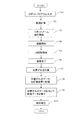
次に、制御部801の制御方法(組立部品の製造方法)について説明する。図4は、実施形態に係る部品の製造方法を示すフローチャートである。
Next, a control method (manufacturing method of assembly parts) of the
本実施形態では、ロボットハンド202を付け替えた後、ロボット200(ロボットハンド202)に、同じ作業を繰り返し行わせるものであるが、リンク216の回転軸C1に対してロボットハンド202の中心軸C2がずれて取り付けられていることがある。そのため、始めの作業時に、リンク216の回転軸C1に対するロボットハンド202の中心軸C2の位置ずれを算出する。ここで、カメラ500によりロボットハンド202のマークMKを撮像できるように、ロボットハンド202には何も把持させていないものとする。また、リンク216の回転軸C1とロボットハンド202の中心軸C2とが平行な状態で、ロボットハンド202がリンク216に取り付けられている。
In this embodiment, after the
まず、CPU401は、ロボットプログラムを入力する(S1)。このロボットプログラムは、組付作業を行うための動作を記述したものである。このロボットプログラムには、上述したように、ある教示点から別の教示点までの移動方法、つまり直線補間、円弧補間、関節補間等の補間方法が記述されている。特に、ロボットハンド202をカメラ500の前を通過させる移動方法は、直線補間で記述されているものとする。つまり、ロボットプログラムには、ある第1教示点からロボットハンド202にワークW1を取得させる位置の近傍の第2教示点へ直線移動するように記述されているものとする。CPU401は、ロボットプログラムに基づき、ロボットアーム201の軌道データを計算する(S2)。
First, the
CPU401は、補正する前の軌道データに基づき、ロボットハンド202のベース部220の座面がXY平面に対して平行な状態、つまり回転軸C1及び中心軸C2がXY平面に対して垂直となる状態にロボットアーム201の姿勢を初期設定する。
Based on the trajectory data before correction, the
そして、CPU401は、補正する前の軌道データに基づき、ロボットアーム201を動作させて、ロボットハンド202をカメラ500に対して移動させる(S3:移動工程、移動処理)。具体的には、CPU401は、リンク216を回転停止させた回転停止状態で、ロボットハンド202がXY平面に対して水平な方向であってカメラ500の撮像範囲内を横切る方向(X軸方向)に移動するよう、ロボットアーム201の動作を開始する。つまり、ロボットハンド202の中心軸C2がXY平面に対して垂直となっている状態で、XY平面に対して水平なX軸方向へ、ロボットハンド202(リンク216)を移動させる。
Then, the
リンク216の回転停止状態とは、ロボットアーム201の関節J6の角度が一定の基準角度(例えば0°)を維持した状態である。本実施形態では、CPU401は、カメラ500の撮像面(つまり、XY平面)に対してリンク216が水平方向に直線移動するように関節J6以外の関節J1〜J5を制御する。
The rotation stop state of the
CPU401は、ロボットハンド202(つまりマークMK)がカメラ500の撮像範囲内に入る前、又は撮像範囲内に在るときに、CPU301に撮像を開始するように指令を送る。CPU301は、この指令を受け、カメラ500に撮像を開始させる(S4:撮像工程、撮像処理)。つまり、CPU301は、カメラ500の撮像範囲内をロボットハンド202が通過中に、リンク216を回転停止状態で、カメラ500にロボットハンド202を撮像させる。カメラ500は、所定のフレームレートでCPU301に撮像画像を送信する。
The
次に、CPU401は、ロボットハンド202(つまりマークMK)がカメラ500の撮像範囲内を通過中に、リンク216を回転軸C1を中心に回転させる回転状態に切り替える。つまり、CPU401は、ロボットハンド202がカメラ500の撮像範囲内を通過中に、ロボットアーム201の関節J6の回転を開始させる(S5)。CPU301は、この回転状態でロボットハンド202をカメラ500に撮像させる。カメラ500は、所定のフレームレートでCPU301に撮像画像を送信する。
Next, the
なお、このリンク216の回転動作は、組立動作を行わせるためのロボットプログラムには記述されていない動作である。つまり、繰り返し行う作業の始めの1回の作業においては、未だ、軌道データを補正する補正データを取得していないので、ステップS2で演算した補正前の軌道データに基づく動作に加えて、リンク216を回転動作させる。具体的には、リンク216の回転軸C1がX軸方向に直線移動するように動作させながら、回転軸C1を中心にリンク216を回転させて、カメラ500に撮像させる。
The rotation operation of the
そして、CPU401は、カメラ500の撮像範囲内で、リンク216を1回転以上、好ましくは3回転以上回転させ、ロボットハンド202(マークMK)が撮像範囲から外れたときに、撮像を完了させるようCPU301に指令する。CPU301は、この指令を受け、カメラ500に撮像を完了させる(S6)。
Then, the
撮像完了後、CPU401は、回転させていたリンク216の回転角度を、本来の軌道データの関節指令値に追従させる。
After completing the imaging, the
CPU301は、以上のステップS4〜S6の撮像処理により得られた複数の撮像画像から、マークMKの移動軌跡が写り込んだ1つの撮像画像を生成する。CPU301は、マークMKの移動軌跡が写り込んだ撮像画像をHDD304等の記憶装置に記録する。
The
図5(a)は、実施形態においてマークの移動軌跡が写り込んだ撮像画像の一例を示す模式図である。撮像画像IMには、リンク216の回転を停止させた回転停止状態E1のマークMKの部分軌跡T1と、リンク216を回転させた回転状態E2のマークMKの部分軌跡T2とからなる移動軌跡T0が写り込んでいる。
FIG. 5A is a schematic diagram illustrating an example of a captured image in which a moving locus of a mark is reflected in the embodiment. The captured image IM has a movement trajectory T0 composed of a partial trajectory T1 of the mark MK in the rotation stop state E1 in which the rotation of the
本実施形態では、部分軌跡T1,T2の撮像時には、リンク216のX軸方向への移動速度を一定としつつ、部分軌跡T1の撮像時には、リンク216の回転を停止させ、部分軌跡T2の撮像時には、リンク216の回転速度を一定とする。また、図5(a)には、リンク216の回転軸C1のX軸方向の移動速度と、部分軌跡T2を撮像する時のマークMKの速度とが同じ場合について図示している。
In the present embodiment, when the partial trajectories T1 and T2 are imaged, the movement speed of the
次にCPU301は、撮像画像中のロボットハンド202の中心軸C2の軌跡、即ちマークMKの移動軌跡T0に基づき、リンク216の回転軸C1に対するロボットハンド202の中心軸C2の位置ずれを算出する(S7:位置ずれ算出工程)。この位置ずれには、位置ずれ量と位置ずれ方向とが含まれている。
Next, the
CPU301は、位置ずれのデータをCPU401に送り、CPU401は、CPU301から取得した位置ずれのデータをHDD404等の記憶装置に記録する(S8)。
The
CPU401は、位置ずれのデータを用いて、ステップS2で求めたロボットアーム201の軌道データを補正する(S9:補正工程、補正処理)。つまりCPU401は、位置ずれのデータを取得した後は、補正後の軌道データに基づきロボットアーム201を動作させる。よって、CPU401は、補正した軌道データに従ってロボットアーム201を動作させ、ロボットハンド202にワークW1を把持させ、ワークW1をワークW2に組付ける組立作業を行わせて組立部品を製造する(S10:作業工程、作業処理)。
The
以上ステップS1〜S9によりロボット制御方法、即ちステップS1〜S10により組立部品の製造方法が実行される。 As described above, the robot control method is executed through steps S1 to S9, that is, the assembly part manufacturing method is executed through steps S1 to S10.
以下、ステップS7の位置ずれ算出処理(位置ずれ算出工程)について具体的に説明する。なお、図5(a)では、ロボットハンド202がX軸方向へ直線移動し、関節J6の回転角度が基準角度(例えば0°)で停止している状態から回転している状態に移行している様子を撮像した撮像画像IMを図示している。軌跡T0は、マークMKの中心点の移動軌跡を示している。
Hereinafter, the positional deviation calculation process (the positional deviation calculation process) in step S7 will be specifically described. In FIG. 5A, the
まず、CPU301は、撮像画像中、回転軸C1の移動方向(X軸方向)と直交する方向(Y軸方向)に対する軌跡T0(部分軌跡T2)の振れ幅(2×R0)を求める。そして、CPU301は、振れ幅(2×R0)に基づき、リンク216の回転軸C1に対するロボットハンド202の中心軸C2の位置ずれ量R0を算出する。
First, the
具体的に説明すると、CPU301は、画像解析して、軌跡T0(部分軌跡T2)の上限のピークP1、P3、P5を通る線(破線)L1を演算する。また、CPU301は、画像解析して、軌跡T0(部分軌跡T2)の下限のピークP2、P4、P6を通る線(破線)L2を演算する。次に、CPU301は、直線L1と直線L2の中間線(一点鎖線)L3を演算する。ここで、直線L3は、関節J6の回転軸C1の軌跡を意味する。次に、CPU301は、直線L3の垂直方向(Y軸方向)の直線L1と直線L2との距離(2×R0)を算出し、これに1/2を乗じて、位置ずれ量R0を算出する。
More specifically, the
また、CPU301は、直線L3(振れ幅(2×R0)の中心位置)に対する部分軌跡T1のオフセット量A0を求める。そして、CPU301は、位置ずれとして、オフセット量A0と位置ずれ量R0とに基づき、リンク216の回転軸C1に対するロボットハンド202の中心軸C2の位置ずれ方向(角度)θ0を算出する。
Further, the
図5(b)は、実施形態において先端リンクの回転軸に対するロボットハンドの中心軸の位置ずれを説明するための図である。図5(a)及び図5(b)を参照しながら具体的に説明すると、まず、CPU301は、部分軌跡T1と直線L3との垂直方向(Y軸方向)の距離(オフセット量)A0を算出する。次に、CPU301は、関節J6の角度を基準角度(0°)の状態としているときのオフセット量A0と位置ずれ量R0とから、位置ずれ方向(位置ずれ角度)θ0=arcsin(A0/R0)を計算する。ここで、関節J6の角度は、リンク215に対するリンク216の角度である。部分軌跡T1を撮像したときの関節J6の角度を基準角度とする。よって、位置ずれ方向θ0は、基準角度に対する角度である。この演算により、部分軌跡T1を撮像したときのリンク216の回転軸C1に対するロボットハンド202の中心軸C2の位置ずれ方向(位置ずれ角度)θ0が求まる。
FIG. 5B is a diagram for explaining the positional deviation of the central axis of the robot hand with respect to the rotation axis of the tip link in the embodiment. Specifically, referring to FIGS. 5A and 5B, first, the
以上、本実施形態によれば、ロボットアーム201を動作させながら、軌跡T0からロボットハンド202の中心軸C2のずれ量R0とずれ角度θ0を高精度に求めることができる。これにより、組付作業中(部品の製造中)にロボット200(つまりロボットアーム201)の動作を止めることなく、ロボットハンド202の位置ずれを測定できるため、タクトタイムを削減することができる。
As described above, according to the present embodiment, the displacement amount R0 and the displacement angle θ0 of the central axis C2 of the
また、ロボットハンド202にマークMKを付与したので、特別な測定治具が不要である。更に、撮像画像IMからマークMKの軌跡T0のピーク間の距離を測定することにより、リンク216の回転精度の影響を受けることなく、位置ずれ量R0を高精度に測定できる。また、ずれ方向θ0についても、軌跡T0の測定結果に基づき、高精度に測定できる。
Further, since the mark MK is given to the
また、位置ずれ方向θ0を、撮像画像IMから部分軌跡T1のオフセット量A0と位置ずれ量R0とを求め、これらの値A0,R0により算出することができるので、演算負荷が小さく、速やかに軌道データを補正することができる。これにより、速やかにロボットアーム201の動作を補正でき、タクトタイムを削減できる。
Further, since the offset direction A0 and the offset amount R0 of the partial trajectory T1 can be obtained from the captured image IM and calculated based on these values A0 and R0, the calculation load is small and the trajectory can be quickly obtained. Data can be corrected. As a result, the operation of the
また、軌道データを補正するようにしたので、ロボットアーム201にロボットハンド202を高精度に装着するための高価な部品も必要なく、コストダウンが可能である。
Further, since the trajectory data is corrected, there is no need for expensive parts for mounting the
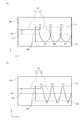
なお、以上の説明では、リンク216を回転させているときのマークMKの速度と、リンク216の回転軸C1のX軸方向の移動速度とが同じ場合について説明したが、これに限定するものでなく、互いの速度が異なっていてもよい。図6(a)及び図6(b)は、実施形態においてマークの移動軌跡が写り込んだ撮像画像の別の例を示す模式図である。
In the above description, the case where the speed of the mark MK when the
図6(a)では、リンク216を回転させているときのマークMKの速度が、リンク216の回転軸C1のX軸方向の移動速度よりも速い場合を図示している。図6(b)では、リンク216を回転させているときのマークMKの速度が、リンク216の回転軸C1のX軸方向の移動速度よりも遅い場合を図示している。いずれの場合であっても、撮像画像IMからピークP1〜P6を抽出することができ、位置ずれ量R0を求めることができる。
FIG. 6A illustrates a case where the speed of the mark MK when the
また、以上の説明では、ステップS3において、カメラ500の撮像面(XY平面)に対してリンク216が直線移動するように、ロボットアーム201を動作させる場合について説明したが、これに限定するものではない。ステップS3において、カメラ500の撮像面(XY平面)に対してリンク216が円弧移動(つまり円弧補間)するように、ロボットアーム201を動作させる場合であってもよい。例えば、関節J2〜J5を固定(停止)させ、関節J1を回転させるように動作させて、カメラ500にロボットハンド202を撮像させてもよい。
In the above description, the case where the
図7は、実施形態においてマークの移動軌跡が写り込んだ撮像画像の更に別の例を示す模式図である。図7では、リンク216を円弧移動させた場合の撮像画像IMを図示している。ステップS7において、CPU301は、図7に示す撮像画像IMから、マークMKの軌跡T0に基づき、リンク216の回転軸C1に対するロボットハンド202の中心軸C2の位置ずれを算出する。具体的に説明すると、CPU301は、画像解析して、軌跡T0(部分軌跡T2)の上限のピークP1、P3、P5を通る円弧線(破線)L1を演算する。また、CPU301は、画像解析して、軌跡T0(部分軌跡T2)の下限のピークP2、P4、P6を通る円弧線(破線)L2を演算する。この場合、上限及び下限のピークは、それぞれ3点以上必要である。したがって、リンク216を3回転以上させて部分軌跡T2を撮像する必要がある。
FIG. 7 is a schematic diagram illustrating still another example of the captured image in which the movement locus of the mark is reflected in the embodiment. FIG. 7 illustrates a captured image IM when the
次に、CPU301は、円弧線L1と円弧線L2の中間線(一点鎖線)L3を演算する。ここで、円弧線L3は、関節J6の回転軸C1の軌跡を意味する。次に、CPU301は、円弧線L3に垂直な方向(半径方向)の直線L1と直線L2との距離(2×R0)を算出し、これに1/2を乗じて、位置ずれ量R0を算出する。
Next, the
また、CPU301は、円弧線L3(振れ幅(2×R0)の半径方向の中心位置)に対する部分軌跡T1のオフセット量A0を求める。そして、CPU301は、位置ずれとして、オフセット量A0と位置ずれ量R0とに基づき、リンク216の回転軸C1に対するロボットハンド202の中心軸C2の位置ずれ方向θ0を算出する。このように、リンク216を円弧移動させてもロボットハンド202の位置ずれを高精度に求めることができる。
Further, the
なお、本発明は、以上説明した実施形態に限定されるものではなく、本発明の技術的思想内で多くの変形が可能である。また、本発明の実施形態に記載された効果は、本発明から生じる最も好適な効果を列挙したに過ぎず、本発明による効果は、本発明の実施形態に記載されたものに限定されない。 The present invention is not limited to the embodiment described above, and many modifications are possible within the technical idea of the present invention. In addition, the effects described in the embodiments of the present invention only list the most preferable effects resulting from the present invention, and the effects of the present invention are not limited to those described in the embodiments of the present invention.
上述の実施形態の1以上の機能を実現するプログラムを、ネットワーク又は記憶媒体を介してシステム又は装置に供給し、そのシステム又は装置のコンピュータにおける1つ以上のプロセッサーがプログラムを読出し実行する処理でも実現可能である。また、1以上の機能を実現する回路(例えば、ASIC)によっても実現可能である。 A program that realizes one or more functions of the above-described embodiments is supplied to a system or apparatus via a network or a storage medium, and is also realized by a process in which one or more processors in a computer of the system or apparatus read and execute the program Is possible. It can also be realized by a circuit (for example, ASIC) that realizes one or more functions.
また、上述の実施形態では、先端リンク216が直線又は円弧移動する場合について説明したが、これに限定するものではない。直線移動及び円弧移動を組み合わせて動作する場合であってもよい。また、これらの移動方法に限らず、任意の動作を行ってもよく、その場合には、軌跡のピークから近似曲線を描くことで関節J6の中心の軌跡を求め、位置ずれ量と位置ずれ方向の計算を行ってもよい。
Moreover, although the above-mentioned embodiment demonstrated the case where the
また、上述の実施形態では、先端リンク216を一定速度で移動させる場合について説明したが、これに限定するものではなく、移動速度が変化してもよい。また、先端リンク216の回転速度も一定の場合について説明したが、回転速度が変化してもよい。
In the above-described embodiment, the case where the
また、上述の実施形態では、カメラ500によるロボットハンド202の撮像中に、リンク216を回転停止状態から回転状態に切り替えた場合について説明したが、これに限定するものではない。リンク216を回転状態から回転停止状態に切り替えてもよく、また、回転状態と回転停止状態とを交互に1回以上行ってもよい。
In the above-described embodiment, the case where the
また、上述の実施形態では、ロボットアーム201が垂直多関節のロボットアームの場合について説明したが、これに限定するものではない。ロボットアーム201が、例えば、水平多関節のロボットアーム、パラレルリンクのロボットアーム、直交ロボット等、種々のロボットアームであってもよい。
In the above-described embodiment, the case where the
また、上述の実施形態では、ロボットハンド202にマークMKが付与されている場合について説明したが、これに限定するものではなく、ロボットハンド202が把持する把持物にマークが付与されている場合であってもよい。この場合、ロボットハンド202の中心軸C2上にマークが位置するようにマークを把持物に形成しておけばよい。この場合、ロボットハンド202に把持物を精度よく把持させる必要がある。したがって、上述の実施形態のようにロボットハンド202にマークMKを付与する方が、簡便であり好ましい。
In the above-described embodiment, the case where the mark MK is given to the
また、上述の実施形態では、ロボット200が行う作業として組付作業について説明したが、組付作業に限定するものではない。エンドエフェクタがツール、又はツールを把持したロボットハンドであって、ねじ止め作業や接着剤を塗布する作業等、種々の作業を行う場合であってもよい。この場合、ツールにマークが付与されていてもよい。
In the above-described embodiment, the assembling work has been described as the work performed by the
また、ロボットハンド202の中心軸上にマークMKが付与されている場合について説明したが、撮像画像上、ロボットハンドの部材に基づき、ロボットハンドの中心軸の位置の軌跡を求めることができれば、マークが付与されていない場合であってもよい。もちろん、マークが付与されている方が、演算負荷が小さいため好ましい。
Further, although the case where the mark MK is given on the central axis of the
また、上述の実施形態では、複数のコンピュータ(CPU)で制御部801が構成されている場合について説明したが、1つのコンピュータ(CPU)で制御部が構成されていてもよい。
Moreover, although the above-mentioned embodiment demonstrated the case where the
また、上述の実施形態では、算出した位置ずれに基づき軌道データを補正する場合について説明したが、これに限定するものではなく、先端リンクに対するロボットハンドの位置ずれそのものを修正してもよい。この場合、先端リンクにロボットハンドをスライドさせるスライド機構を設け、スライド機構により位置ずれを解消させてもよい。 In the above-described embodiment, the case where the trajectory data is corrected based on the calculated positional deviation has been described. However, the present invention is not limited to this, and the positional deviation of the robot hand relative to the tip link itself may be corrected. In this case, a slide mechanism for sliding the robot hand on the tip link may be provided, and the positional deviation may be eliminated by the slide mechanism.
また、上述の実施形態では、組付作業等の作業を行うロボットプログラムにより作成した、補正前の軌道データに基づきロボットアーム201を動作させている最中に、撮像処理を行う場合について説明したが、これに限定するものではない。例えば、ロボットハンド202を撮像するためのロボットプログラムを別途作成しておき、このロボットプログラムにより作成した軌道データに基づきロボットアーム201を動作させている最中に、撮像処理を行ってもよい。
In the above-described embodiment, the case has been described in which imaging processing is performed while the
また、上述の実施形態では、ロボットハンド202を交換したときだけ位置ずれの演算を行う場合について説明したが、組付作業毎に毎回行ってもよい。
Further, in the above-described embodiment, the case where the positional deviation is calculated only when the
また、上述の実施形態では、回転停止状態においてもロボットハンド202の撮像を行う場合について説明したが、回転状態のみロボットハンド202の撮像を行ってもよい。この場合、ロボットハンド202の中心軸C2の位置ずれ方向(角度)は、軌跡の波形のピークにおける関節J6の関節指令値から求めることができる。
In the above-described embodiment, the case where the
また、上述の実施形態では、カメラ500が所定のフレームレートで撮像を行う場合について説明したが、これに限定するものではない。ロボットハンド202(マークMK)を撮像する際に、シャッターを開状態に維持してマークMKの軌跡を撮像するようにしてもよい。
In the above-described embodiment, the case where the
100…ロボット装置、201…ロボットアーム、202…ロボットハンド(エンドエフェクタ)、216…リンク(先端リンク)、500…カメラ(撮像装置)、801…制御部、C1…回転軸、C2…中心軸
DESCRIPTION OF
Claims (13)
前記制御部が、前記ロボットアームを動作させて、撮像範囲内の被写体を撮像する撮像装置に対して前記エンドエフェクタを移動させる移動工程と、
前記制御部が、前記エンドエフェクタが前記撮像範囲内を通過中に、前記先端リンクを回転軸を中心に回転させた回転状態で、前記撮像装置に前記エンドエフェクタを撮像させる撮像工程と、
前記制御部が、前記撮像工程にて得られた撮像画像中の前記エンドエフェクタの中心軸の軌跡に基づき、前記先端リンクの回転軸に対する前記エンドエフェクタの中心軸の位置ずれを算出する位置ずれ算出工程と、を備えたロボット制御方法。 The control unit is a robot control method for controlling the operation of a robot arm having a tip link to which an end effector is attached,
A moving step in which the control unit moves the end effector with respect to an imaging device that images the subject within the imaging range by operating the robot arm;
An imaging step for causing the imaging device to image the end effector in a rotating state in which the control unit rotates the tip link about a rotation axis while the end effector passes through the imaging range;
The control unit calculates a positional deviation of the central axis of the end effector with respect to the rotation axis of the distal end link based on a locus of the central axis of the end effector in the captured image obtained in the imaging process. And a robot control method.
前記撮像画像中、前記回転軸の移動方向と直交する方向に対する前記軌跡の振れ幅に基づき、前記先端リンクの回転軸に対する前記エンドエフェクタの中心軸の位置ずれ量を算出する請求項1又は2に記載のロボット制御方法。 In the misregistration calculation step, the control unit as the misregistration,
The position shift amount of the center axis of the end effector with respect to the rotation axis of the tip link is calculated based on a swing width of the locus with respect to a direction orthogonal to the moving direction of the rotation axis in the captured image. The robot control method described.
前記位置ずれとして、更に、
前記振れ幅の中心位置に対する、前記軌跡のうち前記停止状態で撮像した部分軌跡のオフセット量と、前記位置ずれ量とに基づき、前記先端リンクの回転軸に対する前記エンドエフェクタの中心軸の位置ずれ方向を算出する請求項3に記載のロボット制御方法。 In the imaging step, the control unit further causes the imaging device to image the end effector in a rotation stopped state in which the end link is stopped while the end effector passes through the imaging range.
As the positional deviation,
Based on the offset amount of the partial trajectory imaged in the stopped state of the trajectory with respect to the center position of the deflection width and the positional deviation amount, the positional deviation direction of the central axis of the end effector with respect to the rotation axis of the tip link The robot control method according to claim 3, wherein:
前記制御部が、前記エンドエフェクタが前記撮像範囲内を通過中に、前記先端リンクを回転軸を中心に回転させた回転状態で、前記撮像装置に前記エンドエフェクタを撮像させる撮像工程と、
前記制御部が、前記撮像工程にて得られた撮像画像中の前記エンドエフェクタの中心軸の軌跡に基づき、前記先端リンクの回転軸に対する前記エンドエフェクタの中心軸の位置ずれを算出する位置ずれ算出工程と、
前記制御部が、前記位置ずれ算出工程で算出した位置ずれで、前記ロボットアームの動作を規定する軌道データを補正する補正工程と、
前記制御部が、前記補正工程で補正した軌道データに従って前記ロボットアームを動作させ、前記エンドエフェクタに作業を行わせて部品を製造する作業工程と、を備えた部品の製造方法。 A moving step in which a control unit moves a robot arm to move an end effector attached to a tip link of the robot arm with respect to an imaging device that images a subject in an imaging range;
An imaging step for causing the imaging device to image the end effector in a rotating state in which the control unit rotates the tip link about a rotation axis while the end effector passes through the imaging range;
The control unit calculates a positional deviation of the central axis of the end effector with respect to the rotation axis of the distal end link based on a locus of the central axis of the end effector in the captured image obtained in the imaging process. Process,
A correction step in which the control unit corrects the trajectory data defining the operation of the robot arm with the positional deviation calculated in the positional deviation calculating step;
A work manufacturing method comprising: a work process in which the control unit operates the robot arm according to the trajectory data corrected in the correction process, and causes the end effector to perform a work to manufacture the part.
前記先端リンクに取り付けられたエンドエフェクタと、
撮像範囲内の被写体を撮像する撮像装置と、
前記ロボットアームの動作を制御する制御部と、を備え、
前記制御部は、
前記ロボットアームを動作させて、前記撮像装置に対して前記エンドエフェクタを移動させる移動処理と、
前記エンドエフェクタが前記撮像範囲内を通過中に、前記先端リンクを回転軸を中心に回転させた回転状態で、前記撮像装置に前記エンドエフェクタを撮像させる撮像処理と、
前記撮像処理にて得られた撮像画像中の前記エンドエフェクタの中心軸の軌跡に基づき、前記先端リンクの回転軸に対する前記エンドエフェクタの中心軸の位置ずれを算出する位置ずれ算出処理と、を実行するロボット装置。 A robot arm having a tip link rotatable about a rotation axis;
An end effector attached to the tip link;
An imaging device for imaging a subject within an imaging range;
A control unit for controlling the operation of the robot arm,
The controller is
A movement process of operating the robot arm to move the end effector relative to the imaging device;
An imaging process for causing the imaging device to image the end effector in a rotational state in which the end link is rotated around a rotation axis while the end effector passes through the imaging range;
A positional deviation calculation process for calculating a positional deviation of the central axis of the end effector with respect to the rotation axis of the distal end link based on a locus of the central axis of the end effector in the captured image obtained by the imaging process. Robot device to do.
Priority Applications (1)
| Application Number | Priority Date | Filing Date | Title |
|---|---|---|---|
| JP2016004855A JP2017124468A (en) | 2016-01-14 | 2016-01-14 | Method of controlling robot, method of manufacturing component, robot device, program, and recording medium |
Applications Claiming Priority (1)
| Application Number | Priority Date | Filing Date | Title |
|---|---|---|---|
| JP2016004855A JP2017124468A (en) | 2016-01-14 | 2016-01-14 | Method of controlling robot, method of manufacturing component, robot device, program, and recording medium |
Publications (1)
| Publication Number | Publication Date |
|---|---|
| JP2017124468A true JP2017124468A (en) | 2017-07-20 |
Family
ID=59364448
Family Applications (1)
| Application Number | Title | Priority Date | Filing Date |
|---|---|---|---|
| JP2016004855A Pending JP2017124468A (en) | 2016-01-14 | 2016-01-14 | Method of controlling robot, method of manufacturing component, robot device, program, and recording medium |
Country Status (1)
| Country | Link |
|---|---|
| JP (1) | JP2017124468A (en) |
Cited By (5)
| Publication number | Priority date | Publication date | Assignee | Title |
|---|---|---|---|---|
| CN109421047A (en) * | 2017-08-22 | 2019-03-05 | 发那科株式会社 | Robot system |
| JP2019118993A (en) * | 2017-12-29 | 2019-07-22 | 富士通株式会社 | Robot, self-diagnostic program and self-diagnostic method |
| CN112720471A (en) * | 2020-12-18 | 2021-04-30 | 希美埃(芜湖)机器人技术有限公司 | Automatic spraying method for realizing online tracking of furniture industry based on robot vision |
| CN113165186A (en) * | 2018-09-12 | 2021-07-23 | 佳能株式会社 | Robot system, control device and control method for robot system, image pickup device, control program, and storage medium |
| WO2022254613A1 (en) * | 2021-06-02 | 2022-12-08 | 株式会社Fuji | Method of correcting positional deviation of camera and robot device |
-
2016
- 2016-01-14 JP JP2016004855A patent/JP2017124468A/en active Pending
Cited By (7)
| Publication number | Priority date | Publication date | Assignee | Title |
|---|---|---|---|---|
| CN109421047A (en) * | 2017-08-22 | 2019-03-05 | 发那科株式会社 | Robot system |
| JP2019038040A (en) * | 2017-08-22 | 2019-03-14 | ファナック株式会社 | Robot system |
| US10737384B2 (en) | 2017-08-22 | 2020-08-11 | Fanuc Corporation | Robot system |
| JP2019118993A (en) * | 2017-12-29 | 2019-07-22 | 富士通株式会社 | Robot, self-diagnostic program and self-diagnostic method |
| CN113165186A (en) * | 2018-09-12 | 2021-07-23 | 佳能株式会社 | Robot system, control device and control method for robot system, image pickup device, control program, and storage medium |
| CN112720471A (en) * | 2020-12-18 | 2021-04-30 | 希美埃(芜湖)机器人技术有限公司 | Automatic spraying method for realizing online tracking of furniture industry based on robot vision |
| WO2022254613A1 (en) * | 2021-06-02 | 2022-12-08 | 株式会社Fuji | Method of correcting positional deviation of camera and robot device |
Similar Documents
| Publication | Publication Date | Title |
|---|---|---|
| JP6963748B2 (en) | Robot system and robot system control method | |
| JP6468741B2 (en) | Robot system and robot system calibration method | |
| JP6351293B2 (en) | Robot system and article manufacturing method | |
| JP2017124468A (en) | Method of controlling robot, method of manufacturing component, robot device, program, and recording medium | |
| JP6429473B2 (en) | Robot system, robot system calibration method, program, and computer-readable recording medium | |
| JP6504864B2 (en) | Robot control method, robot apparatus, program, recording medium, and article manufacturing method | |
| JP4759660B2 (en) | Robot arm control device, method, program, integrated electronic circuit, and assembly robot | |
| US8306661B2 (en) | Method and system for establishing no-entry zone for robot | |
| JP6499273B2 (en) | Teaching apparatus and control information generation method | |
| JP6153316B2 (en) | Robot system and control method of robot system | |
| JP2013049102A (en) | Robot control device and method of determining robot attitude | |
| JP4613955B2 (en) | Rotation axis calculation method, program creation method, operation method, and robot apparatus | |
| JP4289619B2 (en) | Tool position correction method for articulated robots | |
| JP2003117861A (en) | Position correcting system of robot | |
| JP4976883B2 (en) | Manipulator system | |
| JP2012171027A (en) | Workpiece picking system | |
| JP2018167334A (en) | Teaching device and teaching method | |
| JP2014240106A (en) | Robot, robot control device, and driving method of robot | |
| JP2015223649A (en) | Gear incorporation system and gear incorporation method | |
| JP2006297559A (en) | Calibration system and robot's calibration method | |
| JP5521506B2 (en) | robot | |
| WO2017175340A1 (en) | Optimization device and vertically articulated robot provided with same | |
| JP2009125839A (en) | Weld teaching position correction system | |
| WO2016151667A1 (en) | Teaching device and method for generating control information | |
| JP3328414B2 (en) | Robot hand attitude control device |