JP2017124074A - Electronic apparatus, system, determination method, determination program and recording medium - Google Patents

Electronic apparatus, system, determination method, determination program and recording medium Download PDF

Info

Publication number
JP2017124074A
JP2017124074A JP2016005807A JP2016005807A JP2017124074A JP 2017124074 A JP2017124074 A JP 2017124074A JP 2016005807 A JP2016005807 A JP 2016005807A JP 2016005807 A JP2016005807 A JP 2016005807A JP 2017124074 A JP2017124074 A JP 2017124074A
Authority
JP
Japan
Prior art keywords
user
unit
golf club
swing
swing analysis
Prior art date
Legal status (The legal status is an assumption and is not a legal conclusion. Google has not performed a legal analysis and makes no representation as to the accuracy of the status listed.)
Pending
Application number
JP2016005807A
Other languages
Japanese (ja)
Inventor
雅文 佐藤
Masafumi Sato
雅文 佐藤
和宏 澁谷
Kazuhiro Shibuya
和宏 澁谷
今井 信行
Nobuyuki Imai
信行 今井
俊彦 加納
Toshihiko Kano
俊彦 加納
Current Assignee (The listed assignees may be inaccurate. Google has not performed a legal analysis and makes no representation or warranty as to the accuracy of the list.)
Seiko Epson Corp
Original Assignee
Seiko Epson Corp
Priority date (The priority date is an assumption and is not a legal conclusion. Google has not performed a legal analysis and makes no representation as to the accuracy of the date listed.)
Filing date
Publication date
Application filed by Seiko Epson Corp filed Critical Seiko Epson Corp
Priority to JP2016005807A priority Critical patent/JP2017124074A/en
Priority to US15/391,523 priority patent/US20170203153A1/en
Priority to CN201710029988.8A priority patent/CN106975200A/en
Publication of JP2017124074A publication Critical patent/JP2017124074A/en
Pending legal-status Critical Current

Links

Images

Classifications

    • AHUMAN NECESSITIES
    • A63SPORTS; GAMES; AMUSEMENTS
    • A63BAPPARATUS FOR PHYSICAL TRAINING, GYMNASTICS, SWIMMING, CLIMBING, OR FENCING; BALL GAMES; TRAINING EQUIPMENT
    • A63B24/00Electric or electronic controls for exercising apparatus of preceding groups; Controlling or monitoring of exercises, sportive games, training or athletic performances
    • A63B24/0003Analysing the course of a movement or motion sequences during an exercise or trainings sequence, e.g. swing for golf or tennis
    • A63B24/0006Computerised comparison for qualitative assessment of motion sequences or the course of a movement
    • AHUMAN NECESSITIES
    • A63SPORTS; GAMES; AMUSEMENTS
    • A63BAPPARATUS FOR PHYSICAL TRAINING, GYMNASTICS, SWIMMING, CLIMBING, OR FENCING; BALL GAMES; TRAINING EQUIPMENT
    • A63B24/00Electric or electronic controls for exercising apparatus of preceding groups; Controlling or monitoring of exercises, sportive games, training or athletic performances
    • A63B24/0087Electric or electronic controls for exercising apparatus of groups A63B21/00 - A63B23/00, e.g. controlling load
    • AHUMAN NECESSITIES
    • A63SPORTS; GAMES; AMUSEMENTS
    • A63BAPPARATUS FOR PHYSICAL TRAINING, GYMNASTICS, SWIMMING, CLIMBING, OR FENCING; BALL GAMES; TRAINING EQUIPMENT
    • A63B69/00Training appliances or apparatus for special sports
    • A63B69/36Training appliances or apparatus for special sports for golf
    • A63B69/3623Training appliances or apparatus for special sports for golf for driving
    • A63B69/3632Clubs or attachments on clubs, e.g. for measuring, aligning
    • AHUMAN NECESSITIES
    • A63SPORTS; GAMES; AMUSEMENTS
    • A63BAPPARATUS FOR PHYSICAL TRAINING, GYMNASTICS, SWIMMING, CLIMBING, OR FENCING; BALL GAMES; TRAINING EQUIPMENT
    • A63B71/00Games or sports accessories not covered in groups A63B1/00 - A63B69/00
    • A63B71/06Indicating or scoring devices for games or players, or for other sports activities
    • A63B71/0619Displays, user interfaces and indicating devices, specially adapted for sport equipment, e.g. display mounted on treadmills
    • A63B71/0622Visual, audio or audio-visual systems for entertaining, instructing or motivating the user
    • A63B2071/0625Emitting sound, noise or music
    • AHUMAN NECESSITIES
    • A63SPORTS; GAMES; AMUSEMENTS
    • A63BAPPARATUS FOR PHYSICAL TRAINING, GYMNASTICS, SWIMMING, CLIMBING, OR FENCING; BALL GAMES; TRAINING EQUIPMENT
    • A63B71/00Games or sports accessories not covered in groups A63B1/00 - A63B69/00
    • A63B71/06Indicating or scoring devices for games or players, or for other sports activities
    • A63B71/0619Displays, user interfaces and indicating devices, specially adapted for sport equipment, e.g. display mounted on treadmills
    • A63B2071/0658Position or arrangement of display
    • A63B2071/0661Position or arrangement of display arranged on the user
    • A63B2071/0663Position or arrangement of display arranged on the user worn on the wrist, e.g. wrist bands
    • AHUMAN NECESSITIES
    • A63SPORTS; GAMES; AMUSEMENTS
    • A63BAPPARATUS FOR PHYSICAL TRAINING, GYMNASTICS, SWIMMING, CLIMBING, OR FENCING; BALL GAMES; TRAINING EQUIPMENT
    • A63B71/00Games or sports accessories not covered in groups A63B1/00 - A63B69/00
    • A63B71/06Indicating or scoring devices for games or players, or for other sports activities
    • A63B71/0619Displays, user interfaces and indicating devices, specially adapted for sport equipment, e.g. display mounted on treadmills
    • A63B2071/0658Position or arrangement of display
    • A63B2071/0661Position or arrangement of display arranged on the user
    • A63B2071/0666Position or arrangement of display arranged on the user worn on the head or face, e.g. combined with goggles or glasses
    • AHUMAN NECESSITIES
    • A63SPORTS; GAMES; AMUSEMENTS
    • A63BAPPARATUS FOR PHYSICAL TRAINING, GYMNASTICS, SWIMMING, CLIMBING, OR FENCING; BALL GAMES; TRAINING EQUIPMENT
    • A63B2220/00Measuring of physical parameters relating to sporting activity
    • A63B2220/30Speed
    • A63B2220/34Angular speed
    • AHUMAN NECESSITIES
    • A63SPORTS; GAMES; AMUSEMENTS
    • A63BAPPARATUS FOR PHYSICAL TRAINING, GYMNASTICS, SWIMMING, CLIMBING, OR FENCING; BALL GAMES; TRAINING EQUIPMENT
    • A63B2220/00Measuring of physical parameters relating to sporting activity
    • A63B2220/40Acceleration

Landscapes

  • Health & Medical Sciences (AREA)
  • General Health & Medical Sciences (AREA)
  • Physical Education & Sports Medicine (AREA)
  • Engineering & Computer Science (AREA)
  • Human Computer Interaction (AREA)
  • Multimedia (AREA)
  • User Interface Of Digital Computer (AREA)
  • Golf Clubs (AREA)

Abstract

PROBLEM TO BE SOLVED: To provide an electronic apparatus that can become an auxiliary for causing a user to comfortably use a state determination function of exercise equipment, and a system, a determination method, a determination program and a recording medium.SOLUTION: An electronic apparatus includes: a determination part for determining a static state of exercise equipment based on a preset determination criterion using output of an inertial sensor; and a notification part for notifying a user of information indicating a change of a state of the exercise equipment till determination is performed.SELECTED DRAWING: Figure 25

Description

本発明は、電子機器、システム、判定方法、判定プログラム、及び記録媒体に関する。   The present invention relates to an electronic device, a system, a determination method, a determination program, and a recording medium.

特許文献1には、モーションセンサーを用いて静止状態での姿勢を検出した後、表示部またはスピーカーからユーザーに対してスイングを開始するよう指示する端末装置が開示されている。端末装置の指示に基づいて、ユーザーがスイングを行うと、端末装置は、ボールの打撃によりインパクトを検出してスイング解析を行う。   Patent Document 1 discloses a terminal device that instructs a user to start a swing from a display unit or a speaker after detecting a posture in a stationary state using a motion sensor. When the user swings based on the instruction of the terminal device, the terminal device detects the impact by hitting the ball and performs a swing analysis.

ところが、ユーザーがアドレス姿勢をとって静止したつもりであっても、スイングを開始するよう端末装置から指示されない場合がある。その原因としては、以下の原因(1)又は原因(2)が考えられる。   However, there are cases where the terminal device does not give an instruction to start a swing even if the user intends to take an address posture and stand still. As the cause, the following cause (1) or cause (2) can be considered.

原因(1)は、端末装置又はモーションセンサーが故障している場合である。   Cause (1) is when the terminal device or the motion sensor is out of order.

原因(2)は、ユーザーは正しい姿勢で静止しているつもりであっても端末装置によって静止と判定されるための条件を運動具が満たしていない場合である。   The cause (2) is a case where the exercise tool does not satisfy the condition for determining that the user is stationary by the terminal device even though the user intends to remain stationary in the correct posture.

このうち、原因(1)の場合は、端末装置又はモーションセンサーの修理を行う必要があるが、原因(2)の場合は、修理の必要はなく、ユーザーがアドレス姿勢を調整すればよいだけである。   Of these, in case (1), it is necessary to repair the terminal device or motion sensor, but in case (2), there is no need for repair, and the user only has to adjust the address posture. is there.

特開2014−100341号公報JP 2014-100341 A

しかしながら、本当の原因が原因(1)及び原因(2)のうち何れであるのかをユーザー自身が判別することは難しい。このため、原因が原因(2)であるにもかかわらず端末装置又はモーションセンサーの製造者へユーザーが修理依頼をしたり、原因が原因(1)であるにもかかわらずアドレス姿勢の改善をユーザーが何度も試みて時間が浪費されたり、といった問題が生じる場合があった。   However, it is difficult for the user himself to determine whether the real cause is the cause (1) or the cause (2). For this reason, the user makes a repair request to the manufacturer of the terminal device or motion sensor regardless of the cause (2), or the user improves the address posture despite the cause (1). However, there were cases where time was wasted by trying many times, and problems such as wasted.

本発明は、以上のような問題点に鑑みてなされたものであり、本発明のいくつかの態様によれば、運動具の状態判定機能をユーザーが快適に利用するための補助となり得る電子機器、システム、判定方法、判定プログラム、記録媒体を提供する。   The present invention has been made in view of the above-described problems, and according to some aspects of the present invention, an electronic device that can assist a user in comfortably using the state determination function of an exercise tool , A system, a determination method, a determination program, and a recording medium.

本発明は前述の課題の少なくとも一部を解決するためになされたものであり、以下の態様または適用例として実現することが可能である。   SUMMARY An advantage of some aspects of the invention is to solve at least a part of the problems described above, and the invention can be implemented as the following aspects or application examples.

[適用例1]
本適用例に係る電子機器は、慣性センサーの出力を用いて、予め設定された判定基準に基づいて運動具の静止状態を判定する判定部と、前記判定に至るまでの間、前記運動具の状態変化を示す情報をユーザーに通知する通知部とを含む。
[Application Example 1]
The electronic device according to the application example includes a determination unit that determines the stationary state of the exercise tool based on a predetermined determination criterion using the output of the inertial sensor, and the exercise tool until the determination is reached. A notification unit for notifying the user of information indicating a state change.

本適用例に係る電子機器によれば、判定に至るまでの間、運動具の状態変化がユーザーに通知されるので、予め設定された判定基準が満たされないときの運動具の状態変化と、判定基準が満たされるときの運動具の状態変化とを、ユーザーに比較させることができる。   According to the electronic device according to this application example, since the user is notified of the change in the state of the exercise tool until the determination is made, the change in the state of the exercise tool when the preset determination criterion is not satisfied, and the determination It is possible to make the user compare the change in the state of the exercise device when the criterion is satisfied.

[適用例2]
本適用例において、前記通知部は、前記運動具が所定期間に亘って所定状態に維持された場合に前記運動具のスイングの開始の許可を前記ユーザーに通知してもよい。
[Application Example 2]
In this application example, the notification unit may notify the user of permission to start swinging the exercise tool when the exercise tool is maintained in a predetermined state for a predetermined period.

したがって、本適用例に係る電子機器のユーザーは、運動開始前に所定のポーズ(例えば、ゴルフのアドレス姿勢などの構えの姿勢)をとることで、電子機器から運動開始の許可を得ることができる。   Therefore, the user of the electronic device according to the application example can obtain permission to start the exercise from the electronic device by taking a predetermined pose (for example, a posture of a posture such as a golf address posture) before starting the exercise. .

[適用例3]
本適用例において、前記通知部は、前記運動具の姿勢変化を示す情報を前記ユーザーに通知してもよい。
[Application Example 3]
In this application example, the notification unit may notify the user of information indicating a change in posture of the exercise tool.

したがって、本適用例に係る電子機器によれば、判定に至るまでの間、運動具の姿勢変化がユーザーに通知されるので、予め設定された判定基準が満たされないときの運動具の姿勢変化と、判定基準が満たされるときの運動具の姿勢変化とを、ユーザーに比較させることができる。   Therefore, according to the electronic device according to this application example, since the posture change of the exercise tool is notified to the user until the determination, the posture change of the exercise tool when the preset determination criterion is not satisfied It is possible to make the user compare the posture change of the exercise tool when the determination criterion is satisfied.

[適用例4]
本適用例において、前記運動具は、ゴルフクラブであり、前記通知部は、前記ゴルフクラブの地平面に対して交差する方向の姿勢変化を前記情報として前記ユーザーに通知してもよい。
[Application Example 4]
In this application example, the exercise tool may be a golf club, and the notification unit may notify the user of a change in posture in a direction intersecting a ground plane of the golf club as the information.

この通知により、ユーザーは、ゴルフクラブを構えた手元の上下方向(ヘッドに視線を向けたユーザーの縦方向)のふらつきの程度を把握することができる。   By this notification, the user can grasp the degree of wobbling in the vertical direction of the hand holding the golf club (the vertical direction of the user with the line of sight toward the head).

[適用例5]
本適用例において、前記運動具は、ゴルフクラブであり、前記通知部は、前記ゴルフクラブの地平面に対して水平方向の姿勢変化を前記情報として前記ユーザーに通知してもよい。
[Application Example 5]
In this application example, the exercise tool may be a golf club, and the notification unit may notify the user of a change in posture in a horizontal direction with respect to a ground plane of the golf club as the information.

この通知により、ユーザーは、ゴルフクラブを構えた手元の左右方向(ヘッドに視線を向けたユーザーの横方向)のふらつきの程度を把握することができる。   By this notification, the user can grasp the degree of wobbling in the left and right direction of the hand holding the golf club (the lateral direction of the user with a line of sight toward the head).

[適用例6]
本適用例において、前記運動具は、ゴルフクラブであり、前記判定基準は、前記ゴルフクラブのライ角に基づき設定されてもよい。
[Application Example 6]
In this application example, the exercise tool may be a golf club, and the determination criterion may be set based on a lie angle of the golf club.

したがって、電子機器は、この判定基準を用いることにより、ゴルフクラブのライ角に適した構えをユーザーにさせることができる。   Therefore, the electronic device can make the user take a posture suitable for the lie angle of the golf club by using this criterion.

[適用例7]
本適用例において、前記通知部は、前記情報と共に前記判定基準を前記ユーザーに通知する。
[Application Example 7]
In this application example, the notification unit notifies the user of the determination criterion together with the information.

したがって、ユーザーは、運動具の状態変化と判定基準との関係を、判定中に確認する
ことができる。
Therefore, the user can confirm the relationship between the state change of the exercise equipment and the determination criterion during the determination.

[適用例8]
本適用例において、前記通知部は、画像、光、音、振動、画像の変化パターン、光の変化パターン、音の変化パターン、及び振動の変化パターンのうち少なくとも1つにより前記通知を行う。
[Application Example 8]
In this application example, the notification unit performs the notification by at least one of an image, light, sound, vibration, an image change pattern, a light change pattern, a sound change pattern, and a vibration change pattern.

したがって、ユーザーは、運動具の状態変化を視覚、触覚、聴覚の少なくとも1つにより認識することができる。   Therefore, the user can recognize the change in the state of the exercise tool by at least one of vision, touch, and hearing.

[適用例9]
本適用例において、前記慣性センサーには、加速度センサー及び角速度センサーの少なくとも一方が含まれる。
[Application Example 9]
In this application example, the inertial sensor includes at least one of an acceleration sensor and an angular velocity sensor.

したがって、電子機器は、運動具の状態(例えば、加速度、速度、位置、姿勢変化、姿勢の少なくとも1つ)を判定することができる。   Therefore, the electronic device can determine the state of the exercise tool (for example, at least one of acceleration, speed, position, posture change, and posture).

[適用例10]
本適用例に係るシステムは、本適用例に係る何れかの電子機器と、前記慣性センサーとを含む。
[Application Example 10]
The system according to this application example includes any one of the electronic devices according to this application example and the inertial sensor.

[適用例11]
本適用例に係るシステムは、本適用例に係る何れかの電子機器と、前記情報を表示する頭部装着型表示装置とを含む。
[Application Example 11]
A system according to this application example includes any electronic device according to this application example, and a head-mounted display device that displays the information.

[適用例12]
本適用例に係るシステムは、本適用例に係る何れかの電子機器と、前記情報を表示する腕部装着型表示装置とを含む。
[Application Example 12]
A system according to this application example includes any electronic device according to this application example, and an arm-mounted display device that displays the information.

[適用例13]
本適用例に係る判定方法は、慣性センサーの出力を用いて、予め設定された判定基準に基づいて運動具の静止状態を判定するステップと、前記判定に至るまでの間、前記運動具の状態変化を示す情報をユーザーに通知するステップとを含む。
[Application Example 13]
The determination method according to this application example includes a step of determining a stationary state of the exercise tool based on a predetermined determination criterion using an output of the inertial sensor, and a state of the exercise tool until the determination is reached. And notifying the user of information indicating the change.

[適用例14]
本適用例に係る判定方法において、前記通知するステップは、前記運動具が所定期間に亘って所定状態に維持された場合に前記運動具のスイングの開始の許可を前記ユーザーに通知する。
[Application Example 14]
In the determination method according to this application example, the notifying step notifies the user of permission to start swinging the exercise tool when the exercise tool is maintained in a predetermined state for a predetermined period.

[適用例15]
本適用例に係る判定方法において、前記通知するステップは、前記運動具の姿勢変化を示す情報を前記ユーザーに通知する。
[Application Example 15]
In the determination method according to this application example, the notifying step notifies the user of information indicating a change in posture of the exercise tool.

[適用例16]
本適用例に係る判定方法において、前記運動具はゴルフクラブであり、前記通知するステップは、前記ゴルフクラブの地平面に対して交差する方向の姿勢変化を前記情報として前記ユーザーに通知する。
[Application Example 16]
In the determination method according to this application example, the exercise tool is a golf club, and the notifying step notifies the user of a change in posture in a direction intersecting a ground plane of the golf club as the information.

[適用例17]
本適用例に係る判定方法において、前記運動具は、ゴルフクラブであり、前記通知する
ステップは、前記ゴルフクラブの地平面に対して水平方向の姿勢変化を前記情報として前記ユーザーに通知する。
[Application Example 17]
In the determination method according to this application example, the exercise tool is a golf club, and the notifying step notifies the user of a change in posture in a horizontal direction with respect to a ground plane of the golf club as the information.

[適用例18]
本適用例に係る判定方法において、前記運動具は、ゴルフクラブであり、前記判定基準は、前記ゴルフクラブに固有のライ角に基づき設定される。
[Application Example 18]
In the determination method according to this application example, the exercise tool is a golf club, and the determination criterion is set based on a lie angle unique to the golf club.

[適用例19]
本適用例に係る判定方法において、前記通知するステップは、前記情報と共に前記判定基準を前記ユーザーに通知する。
[Application Example 19]
In the determination method according to this application example, the notifying step notifies the user of the determination criterion together with the information.

[適用例20]
本適用例に係る判定方法において、前記通知するステップは、画像、光、音、振動、画像の変化パターン、光の変化パターン、音の変化パターン、及び振動の変化パターンのうち少なくとも1つにより前記通知を行う。
[Application Example 20]
In the determination method according to this application example, the notifying step may be performed by at least one of an image, light, sound, vibration, an image change pattern, a light change pattern, a sound change pattern, and a vibration change pattern. Make a notification.

[適用例21]
本適用例に係る判定方法において、前記慣性センサーには、加速度センサー及び角速度センサーの少なくとも一方が含まれる。
[Application Example 21]
In the determination method according to this application example, the inertial sensor includes at least one of an acceleration sensor and an angular velocity sensor.

[適用例22]
本適用例に係る判定プログラムは、慣性センサーの出力を用いて、予め設定された判定基準に基づいて運動具の静止状態を判定するステップと、前記判定に至るまでの間、前記運動具の状態変化を示す情報をユーザーに通知するステップとをコンピューターに実行させる。
[Application Example 22]
The determination program according to this application example uses the output of the inertial sensor to determine the stationary state of the exercise tool based on a predetermined determination criterion and the state of the exercise tool until the determination is reached. Causing the computer to execute a step of notifying the user of information indicating the change.

[適用例23]
本適用例に係る記録媒体は、慣性センサーの出力を用いて、予め設定された判定基準に基づいて運動具の静止状態を判定するステップと、前記判定に至るまでの間、前記運動具の状態変化を示す情報をユーザーに通知するステップと、をコンピューターに実行させる。
[Application Example 23]
The recording medium according to this application example uses the output of the inertial sensor to determine the stationary state of the exercise tool based on a preset determination criterion and the state of the exercise tool until the determination is reached. Causing the computer to execute a step of notifying the user of information indicating the change.

本実施形態のスイング解析システムの構成例を示す図。The figure which shows the structural example of the swing analysis system of this embodiment. センサーユニットの装着例を示す図。The figure which shows the example of mounting | wearing of a sensor unit. センサーユニットの装着位置及び向きの一例を示す図。The figure which shows an example of the mounting position and direction of a sensor unit. ユーザーが打球するまでに行う動作の手順を示す図。The figure which shows the procedure of the operation | movement performed before a user hits a ball. 身体情報及びゴルフクラブ情報の入力画面の一例を示す図。The figure which shows an example of the input screen of body information and golf club information. スイング動作についての説明図。Explanatory drawing about swing operation | movement. スイング解析データの選択画面の一例を示す図。The figure which shows an example of the selection screen of swing analysis data. 表示画面の一例を示す図。The figure which shows an example of a display screen. センサーユニット及びスイング解析装置の構成例を示す図。The figure which shows the structural example of a sensor unit and a swing analyzer. ユーザーの静止時におけるゴルフクラブとセンサーユニットをX軸の負側から視た平面図。The top view which looked at the golf club and sensor unit at the time of a user's still view from the negative side of the X-axis. 3軸角速度の時間変化の一例を示すグラフ。The graph which shows an example of the time change of a triaxial angular velocity. 3軸角速度の合成値の時間変化を示すグラフ。The graph which shows the time change of the composite value of a triaxial angular velocity. 合成値の微分の時間変化を示すグラフ。The graph which shows the time change of the derivative of a synthetic value. シャフトプレーン及びホーガンプレーンを示す図。The figure which shows a shaft plane and a Hogan plane. シャフトプレーンをYZ平面で切った断面図をX軸の負側から視た図。The figure which looked at the sectional view which cut the shaft plane with the YZ plane from the negative side of the X-axis. ホーガンプレーンをYZ平面で切った断面図をX軸の負側から視た図。The figure which looked at the cross-sectional view which cut the Hogan plane in the YZ plane from the negative side of the X-axis. フェース角とクラブパス(入射角)を説明するための図。The figure for demonstrating a face angle and a club path (incidence angle). スイング開始(バックスイング開始)からインパクトまでのシャフト軸回転角の時間変化の一例を示す図。The figure which shows an example of the time change of the shaft axis rotation angle from a swing start (back swing start) to an impact. ダウンスイングにおけるグリップの速度の時間変化の一例を示す図。The figure which shows an example of the time change of the speed of the grip in a downswing. シャフトプレーン及びホーガンプレーンと複数の領域A,B,C,D,Eとの関係の一例を示す図。The figure which shows an example of the relationship between a shaft plane and a Hogan plane, and several area | region A, B, C, D, E. スイング解析処理(スイング解析方法)の手順の一例を示すフローチャート図。The flowchart figure which shows an example of the procedure of a swing analysis process (swing analysis method). サーバー装置の構成例を示す図。The figure which shows the structural example of a server apparatus. サーバー装置と関連するスイング解析装置の処理の手順の一例を示すフローチャート図。The flowchart figure which shows an example of the procedure of the process of the swing analysis apparatus relevant to a server apparatus. サーバー装置の処理の手順の一例を示すフローチャート図。The flowchart figure which shows an example of the process sequence of a server apparatus. インジケーター画面の一例を示す図。The figure which shows an example of an indicator screen. インジケーター画面の別の例を示す図。The figure which shows another example of an indicator screen. インジケーター画面の別の例を示す図。The figure which shows another example of an indicator screen. インジケーター画面の別の例を示す図。The figure which shows another example of an indicator screen. スイング解析処理(スイング解析方法)の手順の一例を示すフローチャート図(図21のフローのうち静止判定に関するステップ(S16)を複数のステップ(S161乃至S166)に細分化したもの)。The flowchart figure which shows an example of the procedure of a swing analysis process (swing analysis method) (step (S16) regarding stationary determination among the flows of FIG. 21 subdivided into a plurality of steps (S161 to S166)). リスト型の表示部の一例を示す図である。It is a figure which shows an example of a list-type display part. ヘッドマウントディスプレイの一例を示す図である。It is a figure which shows an example of a head mounted display.

以下、本発明の好適な実施形態について図面を用いて詳細に説明する。なお、以下に説明する実施の形態は、特許請求の範囲に記載された本発明の内容を不当に限定するものではない。また以下で説明される構成の全てが本発明の必須構成要件であるとは限らない。   DESCRIPTION OF EMBODIMENTS Hereinafter, preferred embodiments of the present invention will be described in detail with reference to the drawings. The embodiments described below do not unduly limit the contents of the present invention described in the claims. Also, not all of the configurations described below are essential constituent requirements of the present invention.

以下では、運動具がゴルフクラブである場合にゴルフスイングの解析を行うスイング解析システムを例に挙げて説明する。   Hereinafter, a swing analysis system that analyzes a golf swing when the exercise tool is a golf club will be described as an example.

1.スイング解析システム
1−1.スイング解析システムの構成
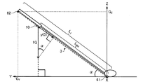
図1は、本実施形態のスイング解析システムの構成例を示す図である。図1に示すように、本実施形態のスイング解析システム1は、センサーユニット10、スイング解析装置20及びサーバー装置30を含んで構成されている。
1. Swing analysis system 1-1. Configuration of Swing Analysis System FIG. 1 is a diagram illustrating a configuration example of a swing analysis system according to this embodiment. As shown in FIG. 1, the swing analysis system 1 of this embodiment includes a sensor unit 10, a swing analysis device 20, and a server device 30.

センサーユニット10(慣性センサーの一例)は、3軸の各軸方向に生じる加速度と3軸の各軸回りに生じる角速度を計測可能であり、図2に示すように、ゴルフクラブ3に装着される。   The sensor unit 10 (an example of an inertial sensor) can measure acceleration generated in each of the three axes and angular velocity generated around each of the three axes, and is attached to the golf club 3 as shown in FIG. .

本実施形態では、図3に示すように、センサーユニット10は、3つの検出軸(x軸,y軸,z軸)のうちの1軸、例えばy軸をゴルフクラブ3のシャフトの長手方向(ゴルフクラブ3の長手方向)に合わせるようにして、シャフトの一部に取り付けられる。望ましくは、センサーユニット10は、打球時の衝撃が伝わり難く、スイング時に遠心力がかかり難いグリップに近い位置に取り付けられる。シャフトは、ゴルフクラブ3のヘッドを除いた柄の部分であり、グリップも含まれる。ただし、センサーユニット10は、ユーザー2の部位(例えば、手やグローブなど)に取り付けられてもよいし、腕時計などのアクセサリーに取り付けられてもよい。   In this embodiment, as shown in FIG. 3, the sensor unit 10 has one of three detection axes (x axis, y axis, z axis), for example, the y axis as the longitudinal direction of the shaft of the golf club 3 ( It is attached to a part of the shaft so as to match the longitudinal direction of the golf club 3. Desirably, the sensor unit 10 is attached at a position close to a grip where impact at the time of hitting is difficult to be transmitted and centrifugal force is difficult to be applied at the time of swing. The shaft is a portion of the handle excluding the head of the golf club 3 and includes a grip. However, the sensor unit 10 may be attached to a part of the user 2 (for example, a hand or a glove), or may be attached to an accessory such as a wristwatch.

ユーザー2は、あらかじめ決められた手順に従って、ゴルフボール4を打球するスイン
グ動作を行う。図4は、本実施形態においてユーザー2が打球するまでに行う動作の手順を示す図である。図4に示すように、ユーザー2は、まず、スイング解析装置20を介してユーザー2の身体情報とユーザー2が使用するゴルフクラブ3に関する情報(ゴルフクラブ情報)などの入力操作を行う(S1)。身体情報は、ユーザー2の身長、腕の長さ及び脚の長さの少なくとも1つの情報を含み、さらに性別の情報やその他の情報を含んでもよい。ゴルフクラブ情報は、ゴルフクラブ3の長さ(クラブ長)の情報及びゴルフクラブ3の種類(番手)の少なくとも一方の情報を含む。次に、ユーザー2は、スイング解析装置20を介して計測開始操作(センサーユニット10に計測を開始させるための操作)を行う(S2)。次に、ユーザー2は、スイング解析装置20からアドレス姿勢(スイング開始前の基本姿勢)をとるように指示する通知(例えば音声による通知)を受けた後(S3のY)、ゴルフクラブ3のシャフトの長手方向がターゲットライン(打球の目標方向)に対して垂直となるようにアドレスの姿勢をとり、静止する(S4)。次に、ユーザー2は、スイング解析装置20からスイングを許可する通知(例えば音声による通知)を受けた後(S5のY)、スイング動作を行い、ゴルフボール4を打球する(S6)。
The user 2 performs a swing motion of hitting the golf ball 4 according to a predetermined procedure. FIG. 4 is a diagram showing a procedure of operations performed until the user 2 hits the ball in the present embodiment. As shown in FIG. 4, the user 2 first performs an input operation such as body information of the user 2 and information (golf club information) regarding the golf club 3 used by the user 2 via the swing analysis device 20 (S1). . The body information includes at least one piece of information on the height, arm length, and leg length of the user 2, and may further include sex information and other information. The golf club information includes information on the length of the golf club 3 (club length) and information on at least one of the types (counts) of the golf club 3. Next, the user 2 performs a measurement start operation (operation for causing the sensor unit 10 to start measurement) via the swing analysis device 20 (S2). Next, the user 2 receives a notification (for example, a notification by voice) instructing to take an address posture (basic posture before starting the swing) from the swing analysis device 20 (Y in S3), and then the shaft of the golf club 3 The address is positioned so that its longitudinal direction is perpendicular to the target line (the target direction of the hit ball), and it stops (S4). Next, after receiving notification (for example, notification by voice) that permits the swing from the swing analysis device 20 (Y in S5), the user 2 performs a swing motion and hits the golf ball 4 (S6).

図5は、スイング解析装置20の表示部25(図9参照)に表示される身体情報及びゴルフクラブ情報の入力画面の一例を示す図である。ユーザー2は、図4のステップS1において、図5に示す入力画面上で身長、性別、年齢、国などの身体情報を入力し、クラブ長(シャフトの長さ)、番手などのゴルフクラブ情報を入力する。なお、身体情報に含まれる情報は、これに限られず、例えば、身体情報は、身長に代えて又は身長とともに腕の長さ及び脚の長さの少なくとも一方の情報を含んでもよい。同様に、ゴルフクラブ情報に含まれる情報は、これに限られず、例えば、ゴルフクラブ情報は、クラブ長と番手のいずれか一方の情報を含まなくてもよいし、他の情報を含んでもよい。   FIG. 5 is a diagram illustrating an example of an input screen for body information and golf club information displayed on the display unit 25 (see FIG. 9) of the swing analysis apparatus 20. In step S1 of FIG. 4, the user 2 inputs physical information such as height, gender, age, and country on the input screen shown in FIG. 5, and enters golf club information such as club length (shaft length) and count. input. The information included in the body information is not limited to this. For example, the body information may include information on at least one of the length of the arm and the length of the leg instead of the height or together with the height. Similarly, the information included in the golf club information is not limited to this. For example, the golf club information may not include information on either the club head or the count, or may include other information.

ユーザー2が図4のステップS2の計測開始操作を行うと、スイング解析装置20はセンサーユニット10に計測開始コマンドを送信し、センサーユニット10は計測開始コマンドを受信して3軸加速度と3軸角速度の計測を開始する。センサーユニット10は、所定周期(例えば1ms)で3軸加速度と3軸角速度を計測し、計測したデータを順次、スイング解析装置20に送信する。センサーユニット10とスイング解析装置20との間の通信は、無線通信でもよいし、有線通信でもよい。   When the user 2 performs the measurement start operation in step S2 of FIG. 4, the swing analysis apparatus 20 transmits a measurement start command to the sensor unit 10, and the sensor unit 10 receives the measurement start command and receives the triaxial acceleration and the triaxial angular velocity. Start measuring. The sensor unit 10 measures the triaxial acceleration and the triaxial angular velocity at a predetermined cycle (for example, 1 ms), and sequentially transmits the measured data to the swing analysis apparatus 20. Communication between the sensor unit 10 and the swing analysis device 20 may be wireless communication or wired communication.

スイング解析装置20は、図4のステップS5に示したスイング開始の許可をユーザー2に通知し、その後、センサーユニット10の計測データに基づいて、ユーザー2がゴルフクラブ3を用いて打球したスイング動作(図4のステップS6)を解析する。   The swing analysis device 20 notifies the user 2 of the permission to start the swing shown in step S5 of FIG. 4, and then the swing motion in which the user 2 hits the golf club 3 based on the measurement data of the sensor unit 10. (Step S6 in FIG. 4) is analyzed.

図6に示すように、ユーザー2が図4のステップS6で行うスイング動作は、スイング(バックスイング)を開始した後、バックスイング中にゴルフクラブ3のシャフトが水平になるハーフウェイバック、バックスイングからダウンスイングに切り替わるトップ、ダウンスイング中にゴルフクラブ3のシャフトが水平になるハーフウェイダウンの各状態を経て、ゴルフボール4を打球するインパクト(打球)に至る動作を含んでいる。そして、スイング解析装置20は、スイングが行われた時刻(日時)、ユーザー2の識別情報や性別、ゴルフクラブ3の種類、スイング動作の解析結果の情報を含むスイング解析データを生成し、ネットワーク40(図1参照)を介して、サーバー装置30に送信する。   As shown in FIG. 6, the swing operation performed by the user 2 in step S <b> 6 of FIG. 4 is a half-way back and back swing in which the shaft of the golf club 3 is horizontal during the back swing after the start of the swing (back swing). It includes an operation that reaches the impact (hit ball) of hitting the golf ball 4 through each state of the top that switches from down to down swing and the half-way down state in which the shaft of the golf club 3 becomes horizontal during the down swing. Then, the swing analysis device 20 generates swing analysis data including the time (date and time) when the swing was performed, the identification information and sex of the user 2, the type of the golf club 3, and information on the analysis result of the swing motion, and the network 40 (See FIG. 1).

サーバー装置30は、スイング解析装置20が送信したスイング解析データを、ネットワーク40を介して受信して保存する。従って、ユーザー2が図4の手順に従ってスイング動作を行う度に、スイング解析装置20により生成されたスイング解析データがサーバー装置30に保存され、スイング解析データリストが構築される。   The server device 30 receives and stores the swing analysis data transmitted from the swing analysis device 20 via the network 40. Therefore, every time the user 2 performs a swing motion according to the procedure of FIG. 4, the swing analysis data generated by the swing analysis device 20 is stored in the server device 30, and a swing analysis data list is constructed.

なお、例えば、スイング解析装置20は、スマートフォンやパーソナルコンピューター
等の情報端末(クライアント端末)で実現され、サーバー装置30は、スイング解析装置20からの要求を処理するサーバーで実現されてもよい。
For example, the swing analysis device 20 may be realized by an information terminal (client terminal) such as a smartphone or a personal computer, and the server device 30 may be realized by a server that processes a request from the swing analysis device 20.

また、ネットワーク40は、インターネット等のワイドエリアネットワーク(WAN:World Area Network)でもよいし、ローカルエリアネットワーク(LAN:Local Area Network)でもよい。あるいは、スイング解析装置20とサーバー装置30とは、例えば、近距離無線通信や有線通信により、ネットワーク40を介さずに通信してもよい。   The network 40 may be a wide area network (WAN: World Area Network) such as the Internet or a local area network (LAN). Alternatively, the swing analysis device 20 and the server device 30 may communicate without going through the network 40 by, for example, short-range wireless communication or wired communication.

本実施形態では、ユーザー2は、スイング解析装置20の操作部23(図9参照)を介してスイング解析アプリケーションを起動させると、スイング解析装置20はサーバー装置30と通信し、スイング解析装置20の表示部25に、例えば、図7に示すようなスイング解析データの選択画面が表示される。この選択画面には、サーバー装置30に保存されているスイング解析データリストに含まれるユーザー2の各スイング解析データについて、時刻(日時)、使用されたゴルフクラブの種類及びスイングの解析結果としての一部の指標の値が含まれている。   In the present embodiment, when the user 2 activates the swing analysis application via the operation unit 23 (see FIG. 9) of the swing analysis device 20, the swing analysis device 20 communicates with the server device 30, and the swing analysis device 20 For example, a swing analysis data selection screen as shown in FIG. 7 is displayed on the display unit 25. In this selection screen, each swing analysis data of the user 2 included in the swing analysis data list stored in the server device 30 is displayed as the time (date and time), the type of golf club used and the analysis result of the swing. The value of the index of the section is included.

図7に示す選択画面の左端には、各スイング解析データに対応づけられたチェックボックスがあり、ユーザー2は、スイング解析装置20の操作を介して、いずれか1つのチェックボックスをチェックした後、この選択画面の下部にあるOKボタンを押下する。これにより、スイング解析装置20はサーバー装置30と通信し、スイング解析装置20の表示部25に、図7の選択画面でチェックされたチェックボックスに対応づけられたスイング解析データを表示する(例えば図8を参照)。   At the left end of the selection screen shown in FIG. 7, there are check boxes associated with each swing analysis data. After the user 2 checks any one check box through the operation of the swing analysis device 20, Press the OK button at the bottom of this selection screen. Accordingly, the swing analysis device 20 communicates with the server device 30 and displays the swing analysis data associated with the check box checked on the selection screen of FIG. 7 on the display unit 25 of the swing analysis device 20 (for example, FIG. 8).

1−2.センサーユニット及びスイング解析装置の構成
図9は、センサーユニット10及びスイング解析装置20の構成例を示す図である。図9に示すように、本実施形態では、センサーユニット10は、加速度センサー12、角速度センサー14、信号処理部16及び通信部18を含んで構成されている。ただし、センサーユニット10は、適宜、これらの構成要素の一部が削除又は変更され、あるいは、他の構成要素が付加された構成であってもよい。
1-2. Configuration of Sensor Unit and Swing Analysis Device FIG. 9 is a diagram illustrating a configuration example of the sensor unit 10 and the swing analysis device 20. As shown in FIG. 9, in this embodiment, the sensor unit 10 includes an acceleration sensor 12, an angular velocity sensor 14, a signal processing unit 16, and a communication unit 18. However, the sensor unit 10 may have a configuration in which some of these components are appropriately deleted or changed, or other components are added as appropriate.

加速度センサー12は、互いに交差する(理想的には直交する)3軸方向の各々に生じる加速度を計測し、計測した3軸加速度の大きさ及び向きに応じたデジタル信号(加速度データ)を出力する。   The acceleration sensor 12 measures acceleration generated in each of three axis directions that intersect (ideally orthogonal) with each other, and outputs a digital signal (acceleration data) corresponding to the magnitude and direction of the measured three axis acceleration. .

角速度センサー14は、互いに交差する(理想的には直交する)3軸の各々の軸回りに生じる角速度を計測し、計測した3軸角速度の大きさ及び向きに応じたデジタル信号(角速度データ)を出力する。   The angular velocity sensor 14 measures an angular velocity generated around each of three axes that intersect each other (ideally orthogonal), and outputs a digital signal (angular velocity data) corresponding to the magnitude and direction of the measured three-axis angular velocity. Output.

信号処理部16は、加速度センサー12と角速度センサー14から、それぞれ加速度データと角速度データを受け取って時刻情報を付して不図示の記憶部に記憶し、記憶した計測データ(加速度データと角速度データ)に時刻情報を付して通信用のフォーマットに合わせたパケットデータを生成し、通信部18に出力する。   The signal processing unit 16 receives acceleration data and angular velocity data from the acceleration sensor 12 and the angular velocity sensor 14, respectively, attaches time information to the storage unit (not shown), and stores the measurement data (acceleration data and angular velocity data). Is attached with time information to generate packet data in accordance with the communication format, and outputs the packet data to the communication unit 18.

加速度センサー12及び角速度センサー14は、それぞれ3軸が、センサーユニット10に対して定義される直交座標系(センサー座標系)の3軸(x軸、y軸、z軸)と一致するようにセンサーユニット10に取り付けられるのが理想的だが、実際には取り付け角の誤差が生じる。そこで、信号処理部16は、取り付け角誤差に応じてあらかじめ算出された補正パラメーターを用いて、加速度データ及び角速度データをxyz座標系のデータに変換する処理を行う。   The acceleration sensor 12 and the angular velocity sensor 14 each have three axes that coincide with the three axes (x axis, y axis, z axis) of the orthogonal coordinate system (sensor coordinate system) defined for the sensor unit 10. Although it is ideal to be attached to the unit 10, an error in the attachment angle actually occurs. Therefore, the signal processing unit 16 performs a process of converting the acceleration data and the angular velocity data into data in the xyz coordinate system using a correction parameter calculated in advance according to the attachment angle error.

さらに、信号処理部16は、加速度センサー12及び角速度センサー14の温度補正処理を行ってもよい。あるいは、加速度センサー12及び角速度センサー14に温度補正の機能が組み込まれていてもよい。   Further, the signal processing unit 16 may perform temperature correction processing of the acceleration sensor 12 and the angular velocity sensor 14. Alternatively, a temperature correction function may be incorporated in the acceleration sensor 12 and the angular velocity sensor 14.

なお、加速度センサー12と角速度センサー14は、アナログ信号を出力するものであってもよく、この場合は、信号処理部16が、加速度センサー12の出力信号と角速度センサー14の出力信号をそれぞれA/D変換して計測データ(加速度データと角速度データ)を生成し、これらを用いて通信用のパケットデータを生成すればよい。   The acceleration sensor 12 and the angular velocity sensor 14 may output analog signals. In this case, the signal processing unit 16 converts the output signal of the acceleration sensor 12 and the output signal of the angular velocity sensor 14 to A / Measurement data (acceleration data and angular velocity data) is generated by D conversion, and packet data for communication may be generated using these.

通信部18は、信号処理部16から受け取ったパケットデータをスイング解析装置20に送信する処理や、スイング解析装置20から計測開始コマンド等の各種の制御コマンドを受信して信号処理部16に送る処理等を行う。信号処理部16は、制御コマンドに応じた各種処理を行う。   The communication unit 18 transmits the packet data received from the signal processing unit 16 to the swing analysis device 20, and receives various control commands such as a measurement start command from the swing analysis device 20 and sends the control data to the signal processing unit 16. Etc. The signal processing unit 16 performs various processes according to the control command.

図9に示すように、本実施形態では、スイング解析装置20(電子機器の一例)は、処理部21(判定部の一例)、通信部22、操作部23、記憶部24、表示部25(通知部の一例)、音出力部(通知部の一例)26及び通信部27を含んで構成されている。ただし、スイング解析装置20は、適宜、これらの構成要素の一部が削除又は変更され、あるいは、他の構成要素が付加された構成であってもよい。   As shown in FIG. 9, in this embodiment, the swing analysis apparatus 20 (an example of an electronic device) includes a processing unit 21 (an example of a determination unit), a communication unit 22, an operation unit 23, a storage unit 24, and a display unit 25 ( An example of a notification unit), a sound output unit (an example of a notification unit) 26 and a communication unit 27 are included. However, the swing analysis apparatus 20 may have a configuration in which some of these components are appropriately deleted or changed, or other components are added as appropriate.

通信部22は、センサーユニット10から送信されたパケットデータを受信し、処理部21に送る処理や、処理部21からの制御コマンドをセンサーユニット10に送信する処理等を行う。   The communication unit 22 receives the packet data transmitted from the sensor unit 10 and performs processing to send to the processing unit 21, processing to transmit a control command from the processing unit 21 to the sensor unit 10, and the like.

操作部23は、ユーザー2の操作に応じたデータを取得し、処理部21に送る処理を行う。操作部23は、例えば、タッチパネル型ディスプレイ、ボタン、キー、マイクなどであってもよい。   The operation unit 23 performs processing to acquire data corresponding to the operation of the user 2 and send the data to the processing unit 21. The operation unit 23 may be, for example, a touch panel display, a button, a key, a microphone, or the like.

記憶部24は、例えば、ROM(Read Only Memory)やフラッシュROM、RAM(Random Access Memory)等の各種ICメモリーやハードディスクやメモリーカードなどの記録媒体等により構成される。記憶部24は、処理部21が各種の計算処理や制御処理を行うためのプログラム(判定プログラムの一例)や、アプリケーション機能を実現するための各種プログラムやデータ等を記憶している。   The storage unit 24 includes, for example, various IC memories such as a ROM (Read Only Memory), a flash ROM, and a RAM (Random Access Memory), a recording medium such as a hard disk and a memory card, and the like. The storage unit 24 stores a program (an example of a determination program) for the processing unit 21 to perform various calculation processes and control processes, and various programs and data for realizing application functions.

本実施形態では、記憶部24には、処理部21によって読み出され、スイング解析処理を実行するためのスイング解析プログラム240が記憶されている。スイング解析プログラム240は、あらかじめ不揮発性の記録媒体(コンピューターに読み取り可能な記録媒体)に記憶されていてもよいし、処理部21がネットワークを介して不図示のサーバーあるいはサーバー装置30からスイング解析プログラム240を受信して記憶部24に記憶させてもよい。   In the present embodiment, the storage unit 24 stores a swing analysis program 240 that is read by the processing unit 21 and that executes a swing analysis process. The swing analysis program 240 may be stored in advance in a non-volatile recording medium (a computer-readable recording medium), or the processing unit 21 receives a swing analysis program from a server (not shown) or the server device 30 via a network. 240 may be received and stored in the storage unit 24.

また、本実施形態では、記憶部24には、ゴルフクラブ情報242、身体情報244及びセンサー装着位置情報246及びスイング解析データ248が記憶される。例えば、ユーザー2が、操作部23を操作して、図5の入力画面から、使用するゴルフクラブ3の仕様情報(例えば、シャフトの長さ、重心の位置、ライ角、フェース角、ロフト角等の情報などの少なくとも一部の情報)を入力し、入力された仕様情報をゴルフクラブ情報242としてもよい。あるいは、ユーザー2が、図4のステップS1において、ゴルフクラブ3の型番を入力(あるいは、型番リストから選択)し、記憶部24にあらかじめ記憶されている型番毎の仕様情報のうち、入力された型番の仕様情報をゴルフクラブ情報242としてもよい。   In the present embodiment, the storage unit 24 stores golf club information 242, body information 244, sensor mounting position information 246, and swing analysis data 248. For example, the user 2 operates the operation unit 23, and the specification information of the golf club 3 to be used (for example, the shaft length, the position of the center of gravity, the lie angle, the face angle, the loft angle, etc.) from the input screen of FIG. Or at least a part of the information), and the inputted specification information may be used as the golf club information 242. Alternatively, the user 2 inputs the model number of the golf club 3 (or is selected from the model number list) in step S1 of FIG. 4 and is input from the specification information for each model number stored in advance in the storage unit 24. The specification information of the model number may be used as the golf club information 242.

また、例えば、ユーザー2が、操作部23を操作して、図5の入力画面から、身体情報を入力し、入力された身体情報を身体情報244としてもよい。また、例えば、図4のステップS1において、ユーザー2が操作部23を操作してセンサーユニット10の装着位置とゴルフクラブ3のグリップエンドとの間の距離を入力し、入力された距離の情報をセンサー装着位置情報246としてもよい。あるいは、センサーユニット10を決められた所定位置(例えば、グリップエンドから20cmの距離など)に装着するものとして、当該所定位置の情報がセンサー装着位置情報246としてあらかじめ記憶されていてもよい。   Further, for example, the user 2 may operate the operation unit 23 to input physical information from the input screen of FIG. 5, and the input physical information may be the physical information 244. Further, for example, in step S1 of FIG. 4, the user 2 operates the operation unit 23 to input the distance between the mounting position of the sensor unit 10 and the grip end of the golf club 3, and the input distance information is obtained. The sensor mounting position information 246 may be used. Alternatively, information on the predetermined position may be stored in advance as sensor mounting position information 246 on the assumption that the sensor unit 10 is mounted at a predetermined position (for example, a distance of 20 cm from the grip end).

スイング解析データ248は、スイングが行われた時刻(日時)、ユーザー2の識別情報や性別、ゴルフクラブ3の種類とともに、処理部21(スイング解析部211)によるスイング動作の解析結果の情報を含むデータである。   The swing analysis data 248 includes information on the result of the swing motion analysis by the processing unit 21 (swing analysis unit 211), along with the time (date and time) at which the swing was performed, the identification information and sex of the user 2, and the type of the golf club 3. It is data.

また、記憶部24は、処理部21の作業領域として用いられ、操作部23が取得したデータ、処理部21が各種プログラムに従って実行した演算結果等を一時的に記憶する。さらに、記憶部24は、処理部21の処理により生成されたデータのうち、長期的な保存が必要なデータを記憶してもよい。   The storage unit 24 is used as a work area of the processing unit 21, and temporarily stores data acquired by the operation unit 23, calculation results executed by the processing unit 21 according to various programs, and the like. Furthermore, the memory | storage part 24 may memorize | store the data which require long-term preservation | save among the data produced | generated by the process of the process part 21. FIG.

表示部25は、処理部21の処理結果を文字、グラフ、表、アニメーション、その他の画像として表示するものである。表示部25は、例えば、CRT、LCD、タッチパネル型ディスプレイ、ヘッドマウントディスプレイ(HMD:Head Mounted Display)などであってもよい。なお、1つのタッチパネル型ディスプレイで操作部23と表示部25の機能を実現するようにしてもよい。   The display unit 25 displays the processing results of the processing unit 21 as characters, graphs, tables, animations, and other images. The display unit 25 may be, for example, a CRT, LCD, touch panel display, head mounted display (HMD), or the like. In addition, you may make it implement | achieve the function of the operation part 23 and the display part 25 with one touchscreen type display.

音出力部26は、処理部21の処理結果を音声やブザー音等の音として出力するものである。音出力部26は、例えば、スピーカーやブザーなどであってもよい。   The sound output unit 26 outputs the processing result of the processing unit 21 as sound such as sound or buzzer sound. The sound output unit 26 may be, for example, a speaker or a buzzer.

通信部27は、ネットワーク40を介してサーバー装置30の通信部32(図22参照)との間でデータ通信を行うものである。例えば、通信部27は、スイング解析処理の終了後、処理部21からスイング解析データ248を受け取って、サーバー装置30の通信部32に送信する処理を行う。また、例えば、通信部27は、図7の選択画面の表示に必要な情報をサーバー装置30の通信部32から受信して処理部21に送る処理や、図7の選択画面における選択情報を処理部21から受け取ってサーバー装置30の通信部32に送信する処理を行う。また、例えば、通信部27は、図8の表示画面の表示に必要な情報をサーバー装置30の通信部32から受信して処理部21に送る処理を行う。   The communication unit 27 performs data communication with the communication unit 32 (see FIG. 22) of the server device 30 via the network 40. For example, the communication unit 27 performs a process of receiving the swing analysis data 248 from the processing unit 21 and transmitting it to the communication unit 32 of the server device 30 after the end of the swing analysis process. Further, for example, the communication unit 27 receives information necessary for displaying the selection screen of FIG. 7 from the communication unit 32 of the server device 30 and sends the information to the processing unit 21, or processes the selection information on the selection screen of FIG. 7. A process of receiving from the unit 21 and transmitting to the communication unit 32 of the server device 30 is performed. For example, the communication unit 27 performs processing for receiving information necessary for displaying the display screen of FIG. 8 from the communication unit 32 of the server device 30 and sending the information to the processing unit 21.

処理部21は、各種プログラムに従い、通信部22を介してセンサーユニット10に制御コマンドを送信する処理や、通信部22を介してセンサーユニット10から受信したデータに対する各種の計算処理を行う。また、処理部21は、各種プログラムに従い、記憶部24からスイング解析データ248を読み出して、通信部27を介してサーバー装置30に送信する処理を行う。また、処理部21は、各種プログラムに従い、通信部27を介して、サーバー装置30に各種の情報を送信し、サーバー装置30から受信した情報に基づいて各種の画面(図7、図8の各画面等)を表示する処理等を行う。また、処理部21は、その他の各種の制御処理を行う。   The processing unit 21 performs processing for transmitting a control command to the sensor unit 10 via the communication unit 22 and various types of calculation processing for data received from the sensor unit 10 via the communication unit 22 according to various programs. In addition, the processing unit 21 performs processing of reading the swing analysis data 248 from the storage unit 24 and transmitting it to the server device 30 via the communication unit 27 according to various programs. Further, the processing unit 21 transmits various types of information to the server device 30 via the communication unit 27 according to various programs, and various screens (each of FIGS. 7 and 8) based on the information received from the server device 30. Screen). The processing unit 21 performs other various control processes.

特に、本実施形態では、処理部21は、スイング解析プログラム240を実行することにより、データ取得部210、スイング解析部211、画像データ生成部212、記憶処理部213、表示処理部214及び音出力処理部215として機能し、ユーザー2のスイング動作を解析する処理(スイング解析処理)を行う。   In particular, in the present embodiment, the processing unit 21 executes the swing analysis program 240, whereby the data acquisition unit 210, the swing analysis unit 211, the image data generation unit 212, the storage processing unit 213, the display processing unit 214, and the sound output. It functions as the processing unit 215 and performs a process of analyzing the swing motion of the user 2 (swing analysis process).

データ取得部210は、通信部22がセンサーユニット10から受信したパケットデータを受け取り、受け取ったパケットデータから時刻情報及び計測データを取得し、記憶処理部213に送る処理を行う。また、データ取得部310は、通信部27がサーバー装置30から受信した各種の画面(図7、図8の各画面等)の表示に必要な情報を受け取って、画像データ生成部212に送る処理を行う。   The data acquisition unit 210 receives the packet data received from the sensor unit 10 by the communication unit 22, acquires time information and measurement data from the received packet data, and performs processing to send to the storage processing unit 213. Further, the data acquisition unit 310 receives information necessary for displaying various screens (such as the screens in FIGS. 7 and 8) received by the communication unit 27 from the server device 30 and sends the information to the image data generation unit 212. I do.

記憶処理部213は、記憶部24に対する各種プログラムや各種データのリード/ライト処理を行う。例えば、記憶処理部213は、データ取得部210から受け取った時刻情報と計測データを対応づけて記憶部24に記憶させる処理や、スイング解析部211が算出した各種の情報やスイング解析データ248等を記憶部24に記憶させる処理を行う。   The storage processing unit 213 performs read / write processing of various programs and various data for the storage unit 24. For example, the storage processing unit 213 associates the time information received from the data acquisition unit 210 with the measurement data and stores the information in the storage unit 24, various information calculated by the swing analysis unit 211, the swing analysis data 248, and the like. Processing to be stored in the storage unit 24 is performed.

スイング解析部211は、センサーユニット10が出力する計測データ(記憶部24に記憶されている計測データ)や操作部23からのデータなどを用いて、ユーザー2のスイング運動を解析し、スイングが行われた時刻(日時)、ユーザー2の識別情報や性別、ゴルフクラブ3の種類、スイング動作の解析結果の情報を含むスイング解析データ248を生成する処理を行う。特に、本実施形態では、スイング解析部211は、スイング動作の解析結果の情報の少なくとも一部として、スイングの各指標の値を算出する。   The swing analysis unit 211 analyzes the swing motion of the user 2 using the measurement data output from the sensor unit 10 (measurement data stored in the storage unit 24), the data from the operation unit 23, and the like. A process for generating swing analysis data 248 including information on the time (date and time) of the user, identification information and sex of the user 2, the type of the golf club 3, and the analysis result of the swing motion is performed. In particular, in the present embodiment, the swing analysis unit 211 calculates the value of each index of the swing as at least part of the information on the analysis result of the swing motion.

スイング解析部211は、スイングの指標として、少なくとも1つの仮想面を算出してもよい。例えば、少なくとも1つの仮想面は、後述する、シャフトプレーンSP(第1仮想面)と、シャフトプレーンSPと第1角度をなすホーガンプレーンHP(第2仮想面)とを含み、スイング解析部211は、この指標として、「シャフトプレーンSP」と「ホーガンプレーンHP」とを算出してもよい。   The swing analysis unit 211 may calculate at least one virtual plane as a swing index. For example, the at least one virtual plane includes a shaft plane SP (first virtual plane) and a Hogan plane HP (second virtual plane) that forms a first angle with the shaft plane SP, which will be described later. As this index, “shaft plane SP” and “Hogan plane HP” may be calculated.

また、スイング解析部211は、スイングの指標として、バックスイング中の第1のタイミングでのゴルフクラブ3のヘッドの位置を算出してもよい。例えば、第1のタイミングは、バックスイング中にゴルフクラブ3の長手方向が水平方向に沿う方向となるハーフウェイバックのときであり、スイング解析部211は、この指標として、後述する「ハーフウェイバック時のヘッドの位置」を算出してもよい。   Further, the swing analysis unit 211 may calculate the position of the head of the golf club 3 at the first timing during the backswing as a swing index. For example, the first timing is a halfway back in which the longitudinal direction of the golf club 3 is in the direction along the horizontal direction during the backswing, and the swing analysis unit 211 uses the “halfway back” described later as this index. The “position of the head at the time” may be calculated.

また、スイング解析部211は、スイングの指標として、ダウンスイング中の第2のタイミングでのゴルフクラブ3のヘッドの位置を算出してもよい。例えば、第2のタイミングは、ダウンスイング中にゴルフクラブ3の長手方向が水平方向に沿う方向となるハーフウェイダウンのときであり、スイング解析部211は、この指標として、後述する「ハーフウェイダウン時のヘッドの位置」を算出してもよい。   Further, the swing analysis unit 211 may calculate the position of the head of the golf club 3 at the second timing during the downswing as a swing index. For example, the second timing is when the golf club 3 is halfway down during the downswing in which the longitudinal direction of the golf club 3 is along the horizontal direction, and the swing analysis unit 211 uses the “halfway down” described later as this index. The “position of the head at the time” may be calculated.

また、スイング解析部211は、スイングの指標として、インパクト(打球時)におけるゴルフクラブ3のヘッドの入射角に基づく指標を算出してもよい。例えば、スイング解析部211は、この指標として、後述する「クラブパス(入射角)ψ」、「アタック角」を算出してもよい。   Further, the swing analysis unit 211 may calculate an index based on the incident angle of the head of the golf club 3 at impact (at the time of hitting) as an index of swing. For example, the swing analysis unit 211 may calculate “club path (incident angle) ψ” and “attack angle”, which will be described later, as this index.

また、スイング解析部211は、スイングの指標として、インパクト(打球時)におけるゴルフクラブ3のヘッドの傾きに基づく指標を算出してもよい。例えば、スイング解析部211は、この指標として、後述する「(絶対)フェース角φ」、「相対フェース角η」を算出してもよい。   Further, the swing analysis unit 211 may calculate an index based on the inclination of the head of the golf club 3 at impact (at the time of hitting) as an index of swing. For example, the swing analysis unit 211 may calculate “(absolute) face angle φ” and “relative face angle η”, which will be described later, as this index.

また、スイング解析部211は、スイングの指標として、インパクト(打球時)におけるゴルフクラブ3の速度に基づく指標を算出してもよい。例えば、スイング解析部211は、この指標として、後述する「ヘッドスピード」を算出してもよい。   In addition, the swing analysis unit 211 may calculate an index based on the speed of the golf club 3 at impact (at the time of hitting) as an index of swing. For example, the swing analysis unit 211 may calculate “head speed” described later as the index.

また、スイング解析部211は、スイングの指標として、シャフトの長手方向を回転軸として、バックスイングの開始時からインパクト(打球時)までの間の所定のタイミングにおけるゴルフクラブ3の前記シャフトの前記回転軸回り(以下、長軸回りと称す)の回転角に基づく指標を算出してもよい。ゴルフクラブ3の長軸回りの回転角は、基準となるタイミングから当該所定のタイミングまでにゴルフクラブ3が長軸回りに回転した角度であってもよい。基準となるタイミングは、バックスイングの開始時であってもよいし、アドレス時であってもよい。また、所定のタイミングは、バックスイングからダウンスイングに移行するとき(トップのとき)であってもよい。例えば、スイング解析部211は、この指標として、後述する「トップ時のシャフト軸回転角θtop」を算出してもよい。 In addition, the swing analysis unit 211 uses the rotation of the shaft of the golf club 3 at a predetermined timing from the start of the back swing to the impact (at the time of hitting the ball) as a swing index with the longitudinal direction of the shaft as the rotation axis. An index based on a rotation angle around an axis (hereinafter referred to as a major axis) may be calculated. The rotation angle around the major axis of the golf club 3 may be an angle obtained by rotating the golf club 3 around the major axis from a reference timing to the predetermined timing. The reference timing may be at the start of the backswing or at the address. Further, the predetermined timing may be when shifting from the backswing to the downswing (at the top). For example, the swing analysis unit 211 may calculate a “shaft shaft rotation angle θ top at the time of top ”, which will be described later, as this index.

また、スイング解析部211は、スイングの指標として、ダウンスイングにおけるゴルフクラブ3のグリップの減速量に基づく指標を算出してもよい。例えば、スイング解析部211は、この指標として、後述する「グリップ減速率R」を算出してもよい。 In addition, the swing analysis unit 211 may calculate an index based on the amount of deceleration of the grip of the golf club 3 during the downswing as a swing index. For example, the swing analysis unit 211 may calculate a “grip deceleration rate R V ” described later as the index.

また、スイング解析部211は、スイングの指標として、ダウンスイングにおけるゴルフクラブ3のグリップの減速期間に基づく指標を算出してもよい。例えば、スイング解析部211は、この指標として、後述する「グリップ減速時間率R」を算出してもよい。 In addition, the swing analysis unit 211 may calculate an index based on the deceleration period of the grip of the golf club 3 in the downswing as the swing index. For example, the swing analysis unit 211 may calculate a “grip deceleration time rate R T ” described later as the index.

ただし、スイング解析部211は、適宜、これらの指標の一部の値を算出しなくてもよいし、その他の指標の値を算出してもよい。   However, the swing analysis unit 211 may not calculate values of some of these indexes as appropriate, or may calculate values of other indexes.

画像データ生成部212は、表示部25に表示される画像に対応する画像データを生成する処理を行う。例えば、画像データ生成部212は、データ取得部210が受け取った各種の情報に基づき、図7に示した選択画面、図8に示した表示画面に対応する画像データを生成する。   The image data generation unit 212 performs processing for generating image data corresponding to the image displayed on the display unit 25. For example, the image data generation unit 212 generates image data corresponding to the selection screen illustrated in FIG. 7 and the display screen illustrated in FIG. 8 based on various types of information received by the data acquisition unit 210.

表示処理部214は、表示部25に対して各種の画像(画像データ生成部212が生成した画像データに対応する画像の他、文字や記号等も含む)を表示させる処理を行う。例えば、表示処理部214は、画像データ生成部212が生成した画像データに基づき、表示部25に、図7に示した選択画面、図8に示した表示画面等を表示させる。また、例えば、画像データ生成部212は、図4のステップS5において、ユーザー2にスイングの開始の許可(運動開始の許可の一例)を通知するための画像や文字等を表示部25に表示させてもよい。また、例えば、表示処理部214は、ユーザー2のスイング運動が終了した後、自動的に、あるいは、ユーザー2の入力操作に応じて、スイング解析部211による解析結果を示す文字や記号等のテキスト情報を表示部25に表示させてもよい。あるいは、センサーユニット10に表示部を設けておいて、表示処理部214は、通信部22を介してセンサーユニット10に画像データを送信し、センサーユニット10の表示部に各種の画像や文字等を表示させてもよい。   The display processing unit 214 performs processing for causing the display unit 25 to display various images (including characters and symbols in addition to images corresponding to the image data generated by the image data generation unit 212). For example, the display processing unit 214 displays the selection screen illustrated in FIG. 7, the display screen illustrated in FIG. 8, and the like on the display unit 25 based on the image data generated by the image data generation unit 212. Further, for example, the image data generation unit 212 causes the display unit 25 to display an image, characters, and the like for notifying the user 2 of permission to start swing (an example of permission to start exercise) in step S5 of FIG. May be. In addition, for example, the display processing unit 214 may display text such as characters and symbols indicating the analysis result by the swing analysis unit 211 automatically or in response to an input operation of the user 2 after the swing motion of the user 2 is completed. Information may be displayed on the display unit 25. Alternatively, a display unit is provided in the sensor unit 10, and the display processing unit 214 transmits image data to the sensor unit 10 via the communication unit 22, and displays various images and characters on the display unit of the sensor unit 10. It may be displayed.

音出力処理部215は、音出力部26に対して各種の音(音声やブザー音等も含む)を出力させる処理を行う。例えば、音出力処理部215は、図4のステップS5において、ユーザー2にスイングの開始の許可を通知するための音を音出力部26から出力させてもよい。また、例えば、音出力処理部215は、ユーザー2のスイング運動が終了した後、自動的に、あるいは、ユーザー2の入力操作に応じて、スイング解析部211による解析結果を示す音や音声を音出力部26から出力させてもよい。あるいは、センサーユニット10に音出力部を設けておいて、音出力処理部215は、通信部22を介してセンサーユニット10に各種の音データや音声データを送信し、センサーユニット10の音出力部に各種の音や音声を出力させてもよい。   The sound output processing unit 215 performs processing for causing the sound output unit 26 to output various sounds (including sound and buzzer sound). For example, the sound output processing unit 215 may cause the sound output unit 26 to output a sound for notifying the user 2 of permission to start the swing in step S5 of FIG. In addition, for example, the sound output processing unit 215 outputs a sound or a sound indicating an analysis result by the swing analysis unit 211 automatically or in response to an input operation of the user 2 after the user 2 swings. You may make it output from the output part 26. FIG. Alternatively, a sound output unit is provided in the sensor unit 10, and the sound output processing unit 215 transmits various sound data and audio data to the sensor unit 10 via the communication unit 22, and the sound output unit of the sensor unit 10. Various sounds and sounds may be output.

なお、スイング解析装置20あるいはセンサーユニット10に振動機構を設けておいて、当該振動機構により各種の情報を振動情報に変換してユーザー2に通知してもよい。   Note that a vibration mechanism may be provided in the swing analysis device 20 or the sensor unit 10, and various information may be converted into vibration information by the vibration mechanism and notified to the user 2.

1−3.スイング解析処理
本実施形態では、アドレス時(静止時)のゴルフクラブ3のヘッドの位置を原点とし、打球の目標方向を示すターゲットラインをX軸、X軸に垂直な水平面上の軸をY軸、鉛直上方向(重力加速度の方向と逆方向)をZ軸とするXYZ座標系(グローバル座標系)を定義する。そして、スイング解析部211は、各指標値を算出するために、センサーユニット10の計測データ(加速度データ及び角速度データ)を用いて、XYZ座標系(グローバル座標系)における、アドレス時からのセンサーユニット10の位置及び姿勢を時系列に算出する。また、スイング解析部211は、センサーユニット10の計測データ(加速度データ又は角速度データ)を用いて、図6に示した、スイング開始、トップ及びインパクトの各タイミングを検出する。そして、スイング解析部211は、センサーユニット10の位置及び姿勢の時系列データと、スイング開始、トップ及びインパクトの各タイミングとを用いて、スイングの各指標(例えば、シャフトプレーン、ホーガンプレーン、ハーフウェイバック時のヘッド位置、ハーフウェイダウン時のヘッド位置、フェース角、クラブパス(入射角)、トップ時のシャフト軸回転角、ヘッドスピード、グリップ減速率及びグリップ減速時間率等)の値を算出し、スイング解析データ248を生成する。
1-3. Swing analysis processing In this embodiment, the position of the head of the golf club 3 at the time of addressing (at rest) is the origin, the target line indicating the target direction of the hit ball is the X axis, and the axis on the horizontal plane perpendicular to the X axis is the Y axis An XYZ coordinate system (global coordinate system) is defined with the vertical direction (the direction opposite to the direction of gravitational acceleration) as the Z axis. Then, the swing analysis unit 211 uses the measurement data (acceleration data and angular velocity data) of the sensor unit 10 to calculate each index value, and the sensor unit from the address in the XYZ coordinate system (global coordinate system). 10 positions and orientations are calculated in time series. Further, the swing analysis unit 211 detects each timing of the swing start, top, and impact shown in FIG. 6 using measurement data (acceleration data or angular velocity data) of the sensor unit 10. Then, the swing analysis unit 211 uses the time series data of the position and orientation of the sensor unit 10 and the timings of the start of the swing, the top, and the impact, and each index of the swing (eg, shaft plane, hogan plane, halfway). Calculate the values of head position at back, head position at halfway down, face angle, club path (incident angle), shaft shaft rotation angle at top, head speed, grip deceleration rate, grip deceleration time rate, etc. The swing analysis data 248 is generated.

[センサーユニット10の位置及び姿勢の算出]
ユーザー2が図4のステップS4の動作を行うと、まず、スイング解析部211は、加速度センサー12が計測した加速度データ等の変化量が所定時間継続して閾値を超えない場合に、ユーザー2がアドレス姿勢で静止していると判定する。次に、スイング解析部211は、当該所定時間内の計測データ(加速度データ及び角速度データ)を用いて、計測データに含まれるオフセット量を計算する。次に、スイング解析部211は、計測データからオフセット量を減算してバイアス補正し、バイアス補正された計測データを用いて、ユーザー2のスイング動作中(図4のステップS6の動作中)のセンサーユニット10の位置及び姿勢を計算する。
[Calculation of position and orientation of sensor unit 10]
When the user 2 performs the operation of step S4 in FIG. 4, first, the swing analysis unit 211 determines that the user 2 does not exceed the threshold for a predetermined amount of time, such as the amount of change in acceleration data measured by the acceleration sensor 12. It is determined that the camera is stationary with the address posture. Next, the swing analysis unit 211 calculates an offset amount included in the measurement data using the measurement data (acceleration data and angular velocity data) within the predetermined time. Next, the swing analysis unit 211 subtracts an offset amount from the measurement data to perform bias correction, and uses the bias-corrected measurement data to detect a sensor during the swing operation of the user 2 (during operation in step S6 in FIG. 4). The position and orientation of the unit 10 are calculated.

具体的には、まず、スイング解析部211は、加速度センサー12が計測した加速度データ、ゴルフクラブ情報242及びセンサー装着位置情報246を用いて、XYZ座標系(グローバル座標系)におけるユーザー2の静止時(アドレス時)のセンサーユニット10の位置(初期位置)を計算する。   Specifically, first, the swing analysis unit 211 uses the acceleration data measured by the acceleration sensor 12, the golf club information 242 and the sensor mounting position information 246 when the user 2 is stationary in the XYZ coordinate system (global coordinate system). The position (initial position) of the sensor unit 10 at the time of addressing is calculated.

図10は、ユーザー2の静止時(アドレス時)におけるゴルフクラブ3とセンサーユニット10をX軸の負側から視た平面図である。ゴルフクラブ3のヘッドの位置61が原点
O(0,0,0)であり、グリップエンドの位置62の座標は(0,G,G)である。ユーザー2は図4のステップS4の動作を行うので、グリップエンドの位置62やセンサーユニット10の初期位置は、そのX座標が0であり、YZ平面上に存在する。図10に示すように、ユーザー2の静止時にセンサーユニット10には重力加速度1Gがかかるので、センサーユニット10が計測するy軸加速度y(0)とゴルフクラブ3のシャフトの傾斜角(シャフトの長手方向と水平面(XY平面)とのなす角)αとの関係は式(1)で表される。
FIG. 10 is a plan view of the golf club 3 and the sensor unit 10 viewed from the negative side of the X axis when the user 2 is stationary (addressing). The head position 61 of the golf club 3 is the origin O (0, 0, 0), and the coordinates of the grip end position 62 are (0, G Y , G Z ). Since the user 2 performs the operation of step S4 in FIG. 4, the grip end position 62 and the initial position of the sensor unit 10 have an X coordinate of 0 and exist on the YZ plane. As shown in FIG. 10, since the gravitational acceleration 1G is applied to the sensor unit 10 when the user 2 is stationary, the y-axis acceleration y (0) measured by the sensor unit 10 and the inclination angle of the shaft of the golf club 3 (the length of the shaft) The relationship between the direction and the angle α formed by the horizontal plane (XY plane) is expressed by Expression (1).

Figure 2017124074
従って、スイング解析部211は、アドレス時(静止時)の任意の時刻間内の任意の加速度データを用いて、式(1)より、傾斜角αを算出することができる。
Figure 2017124074
Therefore, the swing analysis unit 211 can calculate the inclination angle α from Equation (1) using arbitrary acceleration data within an arbitrary time at the time of addressing (at rest).

次に、スイング解析部211は、ゴルフクラブ情報242に含まれるシャフトの長さLからセンサー装着位置情報246に含まれるセンサーユニット10とグリップエンドとの距離LSGを減算して、センサーユニット10とヘッドとの距離LSHを求める。さらに、スイング解析部211は、シャフトの傾斜角αにより特定される方向(センサーユニット10のy軸の負の方向)にヘッドの位置61(原点O)から距離LSHの位置をセンサーユニット10の初期位置とする。 Next, the swing analysis unit 211 subtracts the distance L SG between the sensor unit 10 and the grip end included in the sensor mounting position information 246 from the shaft length L 1 included in the golf club information 242 to obtain the sensor unit 10. The distance L SH between the head and the head is obtained. Further, the swing analysis unit 211 determines the position of the distance L SH from the head position 61 (origin O) in the direction specified by the tilt angle α of the shaft (the negative direction of the y-axis of the sensor unit 10). The initial position.

そして、スイング解析部211は、その後の加速度データを積分してセンサーユニット10の初期位置からの位置の座標を時系列に計算する。   Then, the swing analysis unit 211 integrates subsequent acceleration data and calculates the coordinates of the position of the sensor unit 10 from the initial position in time series.

また、スイング解析部211は、加速度センサー12が計測した加速度データを用いて、XYZ座標系(グローバル座標系)におけるユーザー2の静止時(アドレス時)のセンサーユニット10の姿勢(初期姿勢)を計算する。ユーザー2は図4のステップS4の動作を行うので、ユーザー2のアドレス時(静止時)には、センサーユニット10のx軸はXYZ座標系のX軸と方向が一致し、かつ、センサーユニット10のy軸はYZ平面上にあるため、スイング解析部211は、ゴルフクラブ3のシャフトの傾斜角αより、センサーユニット10の初期姿勢を特定することができる。   In addition, the swing analysis unit 211 calculates the posture (initial posture) of the sensor unit 10 when the user 2 is stationary (at the time of address) in the XYZ coordinate system (global coordinate system) using the acceleration data measured by the acceleration sensor 12. To do. Since the user 2 performs the operation of step S4 in FIG. 4, the direction of the x-axis of the sensor unit 10 coincides with the X-axis of the XYZ coordinate system at the time of the address of the user 2 (at rest), and the sensor unit 10 Since the y-axis is on the YZ plane, the swing analysis unit 211 can identify the initial posture of the sensor unit 10 from the inclination angle α of the shaft of the golf club 3.

そして、スイング解析部211は、その後の角速度センサー14が計測した角速度データを用いた回転演算を行ってセンサーユニット10の初期姿勢からの姿勢の変化を時系列に計算する。センサーユニット10の姿勢は、例えば、X軸、Y軸、Z軸回りの回転角(ロール角、ピッチ角、ヨー角)、クオータ二オン(四元数)などで表現することができる。   Then, the swing analysis unit 211 performs a rotation calculation using the angular velocity data measured by the subsequent angular velocity sensor 14 and calculates the change in posture of the sensor unit 10 from the initial posture in time series. The posture of the sensor unit 10 can be expressed by, for example, rotation angles (roll angle, pitch angle, yaw angle) around the X axis, Y axis, and Z axis, quarter-on (quaternion), and the like.

なお、センサーユニット10の信号処理部16が、計測データのオフセット量を計算し、計測データのバイアス補正を行うようにしてもよいし、加速度センサー12及び角速度センサー14にバイアス補正の機能が組み込まれていてもよい。これらの場合は、スイング解析部211による計測データのバイアス補正が不要となる。   The signal processing unit 16 of the sensor unit 10 may calculate the offset amount of the measurement data and perform bias correction of the measurement data, or the acceleration sensor 12 and the angular velocity sensor 14 may incorporate a bias correction function. It may be. In these cases, the bias correction of the measurement data by the swing analysis unit 211 becomes unnecessary.

[スイング開始、トップ及びインパクトのタイミングの検出]
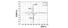
スイング解析部211は、まず、計測データを用いて、ユーザー2が打球したタイミング(インパクトのタイミング)を検出する。例えば、スイング解析部211は、計測データ(加速度データ又は角速度データ)の合成値を計算し、当該合成値に基づいてインパクトのタイミング(時刻)を検出してもよい。
[Detect swing start, top and impact timing]
First, the swing analysis unit 211 detects the timing at which the user 2 hits the ball (impact timing) using the measurement data. For example, the swing analysis unit 211 may calculate a composite value of measurement data (acceleration data or angular velocity data) and detect an impact timing (time) based on the composite value.

具体的には、まず、スイング解析部211は、角速度データ(時刻t毎のバイアス補正された角速度データ)を用いて、各時刻tでの角速度の合成値n0(t)の値を計算する。例えば、時刻tでの角速度データをx(t)、y(t)、z(t)とすると、スイング解析部211は、次の式(2)により、角速度の合成値n(t)を計算する。 Specifically, first, the swing analysis unit 211 calculates a value of a combined value n0 (t) of angular velocities at each time t using the angular velocity data (bias corrected angular velocity data at each time t). For example, assuming that the angular velocity data at time t is x (t), y (t), and z (t), the swing analysis unit 211 calculates the synthesized value n 0 (t) of the angular velocity by the following equation (2). calculate.

Figure 2017124074
次に、スイング解析部211は、各時刻tでの角速度の合成値n(t)を所定範囲に正規化(スケール変換)した合成値n(t)に変換する。例えば、計測データの取得期間における角速度の合成値の最大値をmax(n)とすると、スイング解析部211は、次の式(3)により、角速度の合成値n(t)を0〜100の範囲に正規化した合成値n(t)に変換する。
Figure 2017124074
Next, the swing analysis unit 211 converts the combined value n 0 (t) of angular velocities at each time t into a combined value n (t) normalized (scaled) to a predetermined range. For example, assuming that the maximum value of the combined value of angular velocities in the measurement data acquisition period is max (n 0 ), the swing analysis unit 211 sets the combined value n 0 (t) of angular velocities from 0 to 0 according to the following equation (3). It is converted into a composite value n (t) normalized to a range of 100.

Figure 2017124074
次に、スイング解析部211は、各時刻tでの正規化後の合成値n(t)の微分dn(t)を計算する。例えば、3軸角速度データの計測周期をΔtとすると、スイング解析部211は、次の式(4)により、時刻tでの角速度の合成値の微分(差分)dn(t)を計算する。
Figure 2017124074
Next, the swing analysis unit 211 calculates a differential dn (t) of the combined value n (t) after normalization at each time t. For example, assuming that the measurement period of the triaxial angular velocity data is Δt, the swing analysis unit 211 calculates the differential (difference) dn (t) of the synthesized value of angular velocities at time t by the following equation (4).

Figure 2017124074
図11は、ユーザー2がスイングを行ってゴルフボール4を打ったときの3軸角速度データx(t)、y(t)、z(t)の一例を示す。図11において、横軸は時間(msec)、縦軸は角速度(dps)である。
Figure 2017124074
FIG. 11 shows an example of triaxial angular velocity data x (t), y (t), and z (t) when the user 2 swings and hits the golf ball 4. In FIG. 11, the horizontal axis represents time (msec) and the vertical axis represents angular velocity (dps).

図12は、図11の3軸角速度データx(t),y(t),z(t)から3軸角速度の合成値n0(t)を式(2)に従って計算した後に式(3)に従って0〜100に正規化した合成値n(t)をグラフ表示した図である。図12において、横軸は時間(msec)、縦軸は角速度の合成値である。   FIG. 12 shows the result of calculating the combined value n0 (t) of the triaxial angular velocities from the triaxial angular velocity data x (t), y (t), z (t) of FIG. It is the figure which displayed the synthetic value n (t) normalized to 0-100 in the graph. In FIG. 12, the horizontal axis represents time (msec), and the vertical axis represents the combined value of angular velocities.

図13は、図12の3軸角速度の合成値n(t)からその微分dn(t)を式(4)に従って計算し、グラフ表示した図である。図13において、横軸は時間(msec)、縦軸は3軸角速度の合成値の微分値である。なお、図11及び図12では横軸を0〜5秒で表示しているが、図13では、インパクトの前後の微分値の変化がわかるように、横軸を2秒〜2.8秒で表示している。   FIG. 13 is a graph obtained by calculating the derivative dn (t) from the combined value n (t) of the triaxial angular velocities in FIG. In FIG. 13, the horizontal axis represents time (msec), and the vertical axis represents the differential value of the combined value of the triaxial angular velocities. 11 and 12, the horizontal axis is displayed in 0 to 5 seconds. In FIG. 13, the horizontal axis is in 2 seconds to 2.8 seconds so that the change in the differential value before and after the impact can be seen. it's shown.

次に、スイング解析部211は、合成値の微分dn(t)の値が最大となる時刻と最小となる時刻のうち、先の時刻をインパクトの時刻timpact(インパクトのタイミング)として検出する(図13参照)。通常のゴルフスイングでは、インパクトの瞬間にスイング速度が最大になると考えられる。そして、スイング速度に応じて角速度の合成値の値も変化すると考えられるので、スイング解析部211は、一連のスイング動作の中で角速度の合成値の微分値が最大又は最小となるタイミング(すなわち、角速度の合成値の微分値が正の最大値又は負の最小値になるタイミング)をインパクトのタイミングとして捉えることができる。なお、インパクトによりゴルフクラブ3が振動するため、角速度の合成値の微分値が最大となるタイミングと最小となるタイミングが対になって生じると考えられるが、そのうちの先のタイミングがインパクトの瞬間と考えられる。 Next, the swing analysis unit 211 detects the previous time as the impact time t impact (impact timing) among the time when the value of the derivative dn (t) of the combined value is maximum and minimum ( (See FIG. 13). In a normal golf swing, it is considered that the swing speed becomes maximum at the moment of impact. Then, since it is considered that the value of the combined value of angular velocities also changes according to the swing speed, the swing analysis unit 211 has a timing at which the differential value of the combined value of angular velocities becomes maximum or minimum in a series of swing operations (that is, The timing at which the differential value of the combined value of the angular velocities becomes the maximum positive value or the minimum negative value) can be regarded as the impact timing. In addition, since the golf club 3 vibrates due to the impact, it is considered that the timing at which the differential value of the combined value of the angular velocities is the maximum and the timing at which the differential is the minimum occurs. Conceivable.

次に、スイング解析部211は、インパクトの時刻timpactよりも前で合成値n(t)が0に近づく極小点の時刻をトップの時刻ttop(トップのタイミング)として検出する(図12参照)。通常のゴルフスイングでは、スイング開始後、トップで一旦動作が止まり、その後、徐々にスイング速度が大きくなってインパクトに至ると考えられる。従って、スイング解析部211は、インパクトのタイミングより前で角速度の合成値が0に近づき極小となるタイミングをトップのタイミングとして捉えることができる。 Next, the swing analysis unit 211 detects the time of the minimum point where the composite value n (t) approaches 0 before the impact time t impact as the top time t top (top timing) (see FIG. 12). ). In a normal golf swing, it is considered that after the start of the swing, the operation is temporarily stopped at the top, and then the swing speed is gradually increased to cause an impact. Therefore, the swing analysis unit 211 can recognize the timing at which the combined value of the angular velocities approaches 0 and becomes minimum before the impact timing as the top timing.

次に、スイング解析部211は、トップの時刻ttopの前後で合成値n(t)が所定の閾値以下の区間をトップ区間とし、トップ区間の開始時刻より前で合成値n(t)が所
定の閾値以下となる最後の時刻をスイング開始(バックスイング開始)の時刻tstartとして検出する(図12参照)。通常のゴルフスイングでは、静止した状態からスイング動作を開始し、トップまでにスイング動作が止まることは考えにくい。従って、スイング解析部211は、トップ区間より前で角速度の合成値が所定の閾値以下となる最後のタイミングをスイング動作の開始のタイミングとして捉えることができる。なお、スイング解析部211は、トップの時刻ttopよりも前で、合成値n(t)が0に近づく極小点の時刻をスイング開始の時刻tstartとして検出してもよい。
Next, the swing analysis unit 211 sets a section in which the composite value n (t) is equal to or less than a predetermined threshold before and after the top time t top as a top section, and the composite value n (t) is before the start time of the top section. The last time that is less than or equal to the predetermined threshold is detected as the time t start of the swing start (back swing start) (see FIG. 12). In a normal golf swing, it is unlikely that the swing operation starts from a stationary state and stops until the top. Therefore, the swing analysis unit 211 can recognize the last timing before the combined value of the angular velocities is equal to or less than the predetermined threshold before the top section as the timing for starting the swing motion. Note that the swing analysis unit 211 may detect the time of the minimum point at which the composite value n (t) approaches 0 before the top time t top as the swing start time t start .

なお、スイング解析部211は、3軸加速度データを用いても、同様に、スイング開始、トップ、インパクトの各タイミングを検出することができる。   Note that the swing analysis unit 211 can detect the timing of the start of the swing, the top, and the impact in the same manner using the triaxial acceleration data.

[シャフトプレーン及びホーガンプレーンの算出]
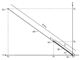
シャフトプレーンは、ユーザー2のスイング開始前のアドレス時(静止状態)において、ターゲットライン(打球の目標方向)とゴルフクラブ3のシャフトの長手方向とで特定される第1仮想面である。また、ホーガンプレーンは、ユーザー2のアドレス時において、ユーザー2の肩付近(肩や首の付け根など)とゴルフクラブのヘッド(あるいは、ゴルフボール4)を結ぶ仮想線とターゲットライン(打球の目標方向)とで特定される第2仮想面である。
[Calculation of shaft plane and Hogan plane]
The shaft plane is a first virtual plane that is specified by the target line (the target direction of the hit ball) and the longitudinal direction of the shaft of the golf club 3 at the time of address before the user 2 starts swinging (still state). In addition, the Hogan plane is a virtual line connecting the vicinity of the shoulder of the user 2 (such as the base of the shoulder or neck) and the golf club head (or the golf ball 4) and the target line (the target direction of the hit ball) at the address of the user 2 ).

図14は、シャフトプレーン及びホーガンプレーンを示す図である。図14には、XYZ座標系(グローバル座標系)のX軸、Y軸、Z軸も表記されている。   FIG. 14 is a diagram illustrating a shaft plane and a Hogan plane. FIG. 14 also shows the X axis, Y axis, and Z axis of the XYZ coordinate system (global coordinate system).

図14に示すように、本実施形態では、打球の目標方向に沿った第1軸としての第1線分51と、ゴルフクラブ3のシャフトの長手方向に沿った第2軸としての第2線分52と、を含み、U1,U2,S1,S2を4つの頂点とする仮想平面をシャフトプレーンSP(第1仮想面)とする。本実施形態では、アドレス時のゴルフクラブ3のヘッドの位置61をXYZ座標系の原点O(0,0,0)とし、第2線分52は、ゴルフクラブ3のヘッドの位置61(原点O)とグリップエンドの位置62とを結ぶ線分である。また、第1線分51は、X軸上のU1,U2を両端として原点Oを中点とする長さULの線分である。ユーザー2がアドレス時に図4のステップS4の動作を行うことでゴルフクラブ3のシャフトがターゲットライン(X軸)に対して垂直となるので、第1線分51は、ゴルフクラブ3のシャフトの長手方向と直交する線分、すなわち第2線分52と直交する線分である。スイング解析部211は、シャフトプレーンSPとして、XYZ座標系における4つの頂点U1,U2,S1,S2の各座標を算出する。   As shown in FIG. 14, in the present embodiment, the first line segment 51 as the first axis along the target direction of the hit ball and the second line as the second axis along the longitudinal direction of the shaft of the golf club 3. And a virtual plane having four vertices U1, U2, S1, and S2 is defined as a shaft plane SP (first virtual plane). In the present embodiment, the head position 61 of the golf club 3 at the time of addressing is the origin O (0, 0, 0) of the XYZ coordinate system, and the second line segment 52 is the head position 61 (origin O of the golf club 3). ) And the grip end position 62. The first line segment 51 is a line segment having a length UL with U1 and U2 on the X axis as both ends and the origin O as a midpoint. Since the user 2 performs the operation of step S4 of FIG. 4 at the time of addressing, the shaft of the golf club 3 becomes perpendicular to the target line (X axis), so the first line segment 51 is the length of the shaft of the golf club 3 This is a line segment orthogonal to the direction, that is, a line segment orthogonal to the second line segment 52. The swing analysis unit 211 calculates the coordinates of the four vertices U1, U2, S1, and S2 in the XYZ coordinate system as the shaft plane SP.

具体的には、まず、スイング解析部211は、傾斜角αとゴルフクラブ情報242に含まれるシャフトの長さLとを用いて、ゴルフクラブ3のグリップエンドの位置62の座標(0,G,G)を計算する。図10に示すように、スイング解析部211は、シャフトの長さLと傾斜角αを用いて、式(5)及び式(6)により、G,Gをそれぞれ計算することができる。 Specifically, first, the swing analysis unit 211 uses the inclination angle α and the shaft length L 1 included in the golf club information 242 to determine the coordinates (0, G) of the grip end position 62 of the golf club 3. Y , G Z ) is calculated. As shown in FIG. 10, the swing analysis unit 211 can calculate G Y and G Z using Equation (5) and Equation (6) using the shaft length L 1 and the inclination angle α. .

Figure 2017124074
Figure 2017124074

Figure 2017124074
次に、スイング解析部211は、ゴルフクラブ3のグリップエンドの位置62の座標(0,G,G)にスケールファクターSを乗算し、シャフトプレーンSPの頂点S1と頂点S2の中点S3の座標(0,S,S)を計算する。すなわち、スイング解析部211は、式(7)及び式(8)により、S及びSをそれぞれ計算する。
Figure 2017124074
Next, the swing analysis unit 211 multiplies the coordinates (0, G Y , G Z ) of the grip end position 62 of the golf club 3 by the scale factor S, and the midpoint S3 of the vertex S1 and the vertex S2 of the shaft plane SP. The coordinates of (0, S Y , S Z ) are calculated. That is, the swing analysis unit 211 calculates SY and SZ , respectively, according to the equations (7) and (8).

Figure 2017124074
Figure 2017124074

Figure 2017124074
図15は、図14のシャフトプレーンSPをYZ平面で切った断面図をX軸の負側から視た図である。図15に示すように、頂点S1と頂点S2の中点S3と原点Oとを結ぶ線分の長さ(シャフトプレーンSPのX軸と直交する方向の幅)は、第2線分52の長さLのS倍となる。このスケールファクターSは、ユーザー2のスイング動作中のゴルフクラブ3の軌跡がシャフトプレーンSPに収まるような値に設定される。例えば、ユーザー2の腕の長さをL2とすると、シャフトプレーンSPのX軸と直交する方向の幅S×Lが、シャフトの長さLと腕の長さLの和の2倍となるように、スケールファクターSを式(9)のように設定してもよい。
Figure 2017124074
FIG. 15 is a cross-sectional view of the shaft plane SP of FIG. 14 taken along the YZ plane, as viewed from the negative side of the X axis. As shown in FIG. 15, the length of the line segment connecting the midpoint S3 of the vertex S1 and the vertex S2 and the origin O (the width of the shaft plane SP in the direction orthogonal to the X axis) is the length of the second line segment 52. It is the S multiple of L 1. The scale factor S is set to a value such that the trajectory of the golf club 3 during the swing motion of the user 2 fits in the shaft plane SP. For example, when the length of the arm of the user 2 is L2, the width S × L 1 in the direction orthogonal to the X axis of the shaft plane SP is twice the sum of the shaft length L 1 and the arm length L 2. The scale factor S may be set as shown in Equation (9) so that

Figure 2017124074
また、ユーザー2の腕の長さLは、ユーザー2の身長Lと相関があり、統計情報に基づき、例えば、ユーザー2が男性の場合は式(10)のような相関式で表され、ユーザー2が女性の場合は式(11)のような相関式で表される。
Figure 2017124074
Further, the arm length L 2 of the user 2 has a correlation with the height L 0 of the user 2, and is represented by a correlation equation such as Expression (10) when the user 2 is male based on statistical information. When the user 2 is a woman, it is expressed by a correlation equation such as equation (11).

Figure 2017124074
Figure 2017124074

Figure 2017124074
従って、スイング解析部211は、身体情報244に含まれるユーザー2の身長Lと性別とを用いて、式(10)又は式(11)により、ユーザーの腕の長さLを算出することができる。
Figure 2017124074
Therefore, the swing analysis unit 211 calculates the user's arm length L 2 according to the equation (10) or the equation (11) using the height L 0 and the gender of the user 2 included in the body information 244. Can do.

次に、スイング解析部211は、中点S3の座標(0,S,S)及びシャフトプレーンSPのX軸方向の幅(第1線分51の長さ)ULを用いて、シャフトプレーンSPの頂点U1の座標(−UL/2,0,0)、頂点U2の座標(UL/2,0,0)、頂点S1の座標(−UL/2,S,S)、S2の座標(UL/2,S,S)を計算する。X軸方向の幅ULは、ユーザー2のスイング動作中のゴルフクラブ3の軌跡がシャフトプレーンSPに収まるような値に設定される。例えば、X軸方向の幅ULを、X軸と直交
する方向の幅S×Lと同じ、すなわち、シャフトの長さLと腕の長さLの和の2倍に設定してもよい。
Next, the swing analysis unit 211 uses the coordinates (0, S Y , S Z ) of the midpoint S3 and the width of the shaft plane SP in the X-axis direction (the length of the first line segment 51) UL. The coordinates of the vertex U1 of the SP (-UL / 2, 0, 0), the coordinates of the vertex U2 (UL / 2, 0, 0), the coordinates of the vertex S1 (-UL / 2, S Y , S Z ), The coordinates (UL / 2, S Y , S Z ) are calculated. The width UL in the X-axis direction is set to a value such that the trajectory of the golf club 3 during the swing motion of the user 2 is within the shaft plane SP. For example, even if the width UL in the X-axis direction is the same as the width S × L 1 in the direction orthogonal to the X-axis, that is, twice the sum of the shaft length L 1 and the arm length L 2. Good.

このようにして、スイング解析部211は、シャフトプレーンSPの4つの頂点U1,U2,S1,S2の座標を算出することができる。   In this way, the swing analysis unit 211 can calculate the coordinates of the four vertices U1, U2, S1, and S2 of the shaft plane SP.

また、図14に示すように、本実施形態では、第1軸としての第1線分51と、第3軸としての第3線分53と、を含み、U1,U2,H1,H2を4つの頂点とする仮想平面をホーガンプレーンHP(第2仮想面)とする。第3線分53は、ユーザー2の両肩を結ぶ線分付近にある所定位置63とゴルフクラブ3のヘッドの位置62とを結ぶ線分である。ただし、第3線分53は、所定位置63とゴルフボール4の位置とを結ぶ線分であってもよい。スイング解析部211は、ホーガンプレーンHPとして、XYZ座標系における4つの頂点U1,U2,H1,H2の各座標を算出する。   Moreover, as shown in FIG. 14, in this embodiment, the first line segment 51 as the first axis and the third line segment 53 as the third axis are included, and U1, U2, H1, and H2 are set to four. A virtual plane having two vertices is defined as a Hogan plane HP (second virtual plane). The third line segment 53 is a line segment that connects a predetermined position 63 in the vicinity of the line segment that connects both shoulders of the user 2 and the head position 62 of the golf club 3. However, the third line segment 53 may be a line segment that connects the predetermined position 63 and the position of the golf ball 4. The swing analysis unit 211 calculates the coordinates of the four vertices U1, U2, H1, and H2 in the XYZ coordinate system as the Hogan plane HP.

具体的には、まず、スイング解析部211は、アドレス時(静止時)のおけるゴルフクラブ3のグリップエンドの位置62の座標(0,G,G)と、身体情報244に基づくユーザー2の腕の長さLとを用いて、所定位置63を推定し、その座標(A,A,A)を計算する。 Specifically, first, the swing analysis unit 211 determines the user 2 based on the coordinates (0, G Y , G Z ) of the grip end position 62 of the golf club 3 at the time of addressing (at rest) and the physical information 244. The predetermined position 63 is estimated using the arm length L 2 and the coordinates (A X , A Y , A Z ) are calculated.

図16は、図14のホーガンプレーンHPをYZ平面で切った断面図をX軸の負側から視た図である。図16では、ユーザー2の両肩を結ぶ線分の中点を所定位置63としており、所定位置63はYZ平面上に存在する。従って、所定位置63のX座標Aは0である。そして、図16に示すように、スイング解析部211は、ゴルフクラブ3のグリップエンドの位置62をZ軸の正方向にユーザー2の腕の長さLだけ移動させた位置が所定位置63であると推定する。従って、スイング解析部211は、所定位置63のY座標Aをグリップエンドの位置62のY座標Gと同じ値とする。また、スイング解析部211は、所定位置63のZ座標Aを、式(12)のように、グリップエンドの位置62のZ座標Gとユーザー2の腕の長さLの和として計算する。 FIG. 16 is a cross-sectional view of the Hogan plane HP of FIG. 14 taken along the YZ plane, as viewed from the negative side of the X axis. In FIG. 16, the midpoint of the line segment connecting both shoulders of the user 2 is a predetermined position 63, and the predetermined position 63 exists on the YZ plane. Therefore, the X-coordinate A X a predetermined position 63 is zero. Then, as shown in FIG. 16, the swing analysis unit 211 has a predetermined position 63 that is a position obtained by moving the grip end position 62 of the golf club 3 in the positive direction of the Z axis by the arm length L 2 of the user 2. Presume that there is. Accordingly, the swing analyzer 211, a Y coordinate A Y of the predetermined position 63 to the same value as the Y-coordinate G Y position 62 of the grip end. Further, the swing analysis unit 211 calculates the Z coordinate A Z of predetermined positions 63, as in Equation (12), as the sum of the length L 2 of the arm of the Z coordinate G Z and user 2 position 62 of the grip end To do.

Figure 2017124074
次に、スイング解析部211は、所定位置63のY座標A及びZ座標AにそれぞれスケールファクターHを乗算し、ホーガンプレーンHPの頂点H1と頂点H2の中点H3の座標(0,H,H)を計算する。すなわち、スイング解析部211は、式(13)及び式(14)により、H及びHをそれぞれ計算する。
Figure 2017124074
Next, the swing analysis unit 211 multiplies the Y coordinate A Y and the Z coordinate AZ of the predetermined position 63 by the scale factor H, respectively, and coordinates (0, H) of the midpoint H3 of the vertex H1 and the vertex H2 of the Hogan plane HP. Y , H Z ) is calculated. That is, the swing analysis unit 211 calculates H Y and H Z according to the equations (13) and (14), respectively.

Figure 2017124074
Figure 2017124074

Figure 2017124074
図16に示すように、頂点H1と頂点H2の中点H3と原点Oとを結ぶ線分の長さ(ホーガンプレーンHPのX軸と直交する方向の幅)は、第3線分53の長さL3のH倍となる。このスケールファクターHは、ユーザー2のスイング動作中のゴルフクラブ3の軌跡
がホーガンプレーンHPに収まるような値に設定される。例えば、ホーガンプレーンHPは、シャフトプレーンSPと同じ形及び大きさとしてもよい。この場合、ホーガンプレーンHPのX軸と直交する方向の幅H×Lが、シャフトプレーンSPのX軸と直交する方向の幅S×Lと一致し、ゴルフクラブ3のシャフトの長さLとユーザー2の腕の長さLの和の2倍となる。従って、スイング解析部211は、スケールファクターHを式(15)により、計算することができる。
Figure 2017124074
As shown in FIG. 16, the length of the line segment connecting the midpoint H3 of the vertex H1 and the vertex H2 and the origin O (the width in the direction perpendicular to the X axis of the Hogan plane HP) is the length of the third line segment 53. It becomes H times L3. This scale factor H is set to a value such that the trajectory of the golf club 3 during the swing motion of the user 2 falls within the Hogan plane HP. For example, the Hogan plane HP may have the same shape and size as the shaft plane SP. In this case, the width H × L 3 in the direction orthogonal to the X axis of the Hogan plane HP matches the width S × L 1 in the direction orthogonal to the X axis of the shaft plane SP, and the length L of the shaft of the golf club 3 This is twice the sum of the arm length L 2 of 1 and the user 2. Therefore, the swing analysis unit 211 can calculate the scale factor H by the equation (15).

Figure 2017124074
また、スイング解析部211は、所定位置63のY座標A及びZ座標Aを用いて、式(13)により、第3線分53の長さL3を計算することができる。
Figure 2017124074
Further, the swing analysis unit 211 can calculate the length L3 of the third line segment 53 by using the Y coordinate AY and the Z coordinate AZ of the predetermined position 63 according to the equation (13).

次に、処理部21は、中点H3の座標(0,H,H)及びホーガンプレーンHPのX軸方向の幅(第1線分51の長さ)ULを用いて、ホーガンプレーンHPの頂点H1の座標(−UL/2,H,H)、H2の座標(UL/2,H,H)を計算する。なお、ホーガンプレーンHPの2つの頂点U1,U2はシャフトプレーンSPと共通するため、スイング解析部211は、ホーガンプレーンHPの頂点U1,U2の座標をあらためて計算する必要はない。 Next, the processing unit 21 uses the coordinates (0, H Y , H Z ) of the midpoint H3 and the width (the length of the first line segment 51) UL of the Hogan plane HP in the X-axis direction to use the Hogan plane HP. The coordinates of the vertex H1 (−UL / 2, H Y , H Z ) and the coordinates of H2 (UL / 2, H Y , H Z ) are calculated. Since the two vertices U1 and U2 of the Hogan plane HP are common to the shaft plane SP, the swing analysis unit 211 does not need to newly calculate the coordinates of the vertices U1 and U2 of the Hogan plane HP.

このようにして、スイング解析部211は、ホーガンプレーンHPの4つの頂点U1,U2,H1,H2の座標を算出することができる。   In this way, the swing analysis unit 211 can calculate the coordinates of the four vertices U1, U2, H1, and H2 of the Hogan plane HP.

シャフトプレーンSP(第1仮想面)とホーガンプレーンHP(第2仮想面)により挟まれる領域は「Vゾーン」と呼ばれ、バックスイング中やダウンスイング中のゴルフクラブ3のヘッドの位置とVゾーンとの関係により、打球の軌道(球筋)をある程度推測することができる。例えば、バックスイングあるいはダウンスイング中の所定のタイミングで
ゴルフクラブ3のヘッドがVゾーンよりも低い空間に存在する場合はフック系の打球となりやすい。また、バックスイングあるいはダウンスイング中の所定のタイミングでゴルフクラブ3のヘッドがVゾーンよりも高い空間に存在する場合はスライス系の打球となりやすい。本実施形態では、図16から明らかなように、シャフトプレーンSPとホーガンプレーンHPとのなす第1角度βは、ゴルフクラブ3のシャフトの長さLとユーザー2の腕の長さLに応じて決定される。すなわち、第1角度βは、固定値ではなく、ゴルフクラブ3の種類やユーザー2の身体に応じて決まるので、ユーザー2のスイングを診断する指標としてより適切なシャフトプレーンSP及びホーガンプレーンHP(Vゾーン)が算出される。
An area sandwiched between the shaft plane SP (first imaginary plane) and the Hogan plane HP (second imaginary plane) is called “V zone”, and the position of the head of the golf club 3 during the backswing or downswing and the V zone Therefore, it is possible to estimate the trajectory (ball muscle) of the hit ball to some extent. For example, when the head of the golf club 3 exists in a space lower than the V zone at a predetermined timing during the backswing or downswing, it is likely to be a hook-type hit ball. In addition, when the head of the golf club 3 exists in a space higher than the V zone at a predetermined timing during the backswing or the downswing, a slicing ball is likely to occur. In this embodiment, as is apparent from FIG. 16, the first angle β formed by the shaft plane SP and the Hogan plane HP is equal to the shaft length L 1 of the golf club 3 and the arm length L 2 of the user 2. Will be decided accordingly. That is, since the first angle β is not a fixed value but is determined according to the type of the golf club 3 and the body of the user 2, the shaft plane SP and the Hogan plane HP (V Zone) is calculated.

[ハーフウェイバック時及びハーフウェイダウン時のヘッド位置の算出]
ハーフウェイバック時のヘッド位置は、ハーフウェイバックの瞬間、直前又は直後のヘッドの位置であり、ハーフウェイダウン時のヘッド位置は、ハーフウェイバックの瞬間、直前又は直後のヘッドの位置である。
[Calculation of head position at halfway back and halfway down]
The head position at the time of halfway back is the position of the head immediately before or immediately after the halfway back, and the head position at the time of halfway back is the position of the head immediately before, immediately after or immediately after the halfway back.

まず、スイング解析部211は、スイング開始の時刻tstartからインパクトの時刻timpactまでの各時刻tにおけるセンサーユニット10の位置及び姿勢を用いて、各時刻tにおけるヘッドの位置及びグリップエンドの位置を計算する。 First, the swing analysis unit 211 uses the position and posture of the sensor unit 10 at each time t from the swing start time t start to the impact time t impact to determine the head position and the grip end position at each time t. calculate.

具体的には、スイング解析部211は、各時刻tにおいて、センサーユニット10の位置から、センサーユニット10の姿勢により特定されるy軸の正の方向に距離LSHだけ離れた位置をヘッドの位置とし、ヘッドの位置の座標を計算する。前述の通り、距離L
は、センサーユニット10とヘッドとの距離である。また、スイング解析部211は、各時刻tにおいて、センサーユニット10の位置から、センサーユニット10の姿勢により特定されるy軸の負の方向に距離LSGだけ離れた位置をグリップエンドの位置とし、グリップエンドの位置の座標を計算する。前述の通り、距離LSGは、センサーユニット10とグリップエンドとの距離である。
Specifically, at each time t, the swing analysis unit 211 sets a position separated from the position of the sensor unit 10 by a distance LSH in the positive direction of the y-axis specified by the attitude of the sensor unit 10 as the head position. Calculate the coordinates of the head position. As mentioned above, the distance L S
H is the distance between the sensor unit 10 and the head. In addition, the swing analysis unit 211 sets the grip end position as a grip end position at each time t from the position of the sensor unit 10 by the distance LSG in the negative y-axis direction specified by the attitude of the sensor unit 10. Calculate the coordinates of the end position. As described above, the distance LSG is a distance between the sensor unit 10 and the grip end.

次に、スイング解析部211は、ヘッドの位置の座標とグリップエンドの位置の座標とを用いて、ハーフウェイバックのタイミングとハーフウェイダウンのタイミングを検出する。   Next, the swing analysis unit 211 detects the halfway back timing and the halfway down timing using the coordinates of the head position and the coordinates of the grip end.

具体的には、スイング解析部211は、スイング開始の時刻tstartからインパクトの時刻timpactまでの各時刻tにおけるヘッドの位置のZ座標とグリップエンドの位置のZ座標との差分ΔZを計算する。そして、スイング解析部211は、スイング開始の時刻tstartからトップの時刻ttopまでの間でΔZの符号が反転する時刻tHWBをハーフウェイバックのタイミングとして検出する。また、スイング解析部211は、トップの時刻ttopからインパクトの時刻timpactまでの間でΔZの符号が反転する時刻tHWDをハーフウェイダウンのタイミングとして検出する。 Specifically, the swing analysis unit 211 calculates a difference ΔZ between the Z coordinate of the head position and the Z coordinate of the grip end position at each time t from the swing start time t start to the impact time t impact. . Then, the swing analysis unit 211 detects a time t HWB at which the sign of ΔZ is inverted between the swing start time t start and the top time t top as the halfway back timing. Further, the swing analysis unit 211 detects a time t HWD at which the sign of ΔZ is inverted between the top time t top and the impact time t impact as the halfway down timing.

そして、スイング解析部211は、時刻tHWBにおけるヘッドの位置をハーフウェイバック時のヘッドの位置とし、時刻tHWDにおけるヘッドの位置をハーフウェイダウン時のヘッドの位置とする。 Then, the swing analysis unit 211 sets the head position at time t HWB as the head position at the time of halfway back, and sets the head position at time t HWD as the head position at the time of halfway down.

[ヘッドスピードの算出]
ヘッドスピードは、インパクトのとき(インパクトの瞬間、インパクトの直前又はインパクトの直後)のヘッドの速度の大きさである。例えば、スイング解析部211は、インパクトの時刻timpactにおけるヘッドの位置の座標とその1つ前の時刻におけるヘッドの位置の座標との差分により、インパクトの時刻timpactにおけるヘッドの速度を計算する。そして、スイング解析部211は、ヘッドスピードとして当該ヘッドの速 度の大きさを計算する。
[Calculation of head speed]
The head speed is the magnitude of the head speed at the time of impact (instant of impact, immediately before impact, or immediately after impact). For example, the swing analyzer 211, the difference of the coordinates of the position of the head at time t impact of the impact and the position of the coordinates of the head at the previous time, to calculate the velocity of the head at time t impact of the impact. Then, the swing analysis unit 211 calculates the magnitude of the head speed as the head speed.

[フェース角及びクラブパス(入射角)の算出]
フェース角は、インパクトにおけるゴルフクラブ3のヘッドの傾きに基づく指標であり、クラブパス(入射角)は、インパクトにおけるゴルフクラブ3のヘッドの軌道に基づく指標である。
[Calculation of face angle and club path (incident angle)]
The face angle is an index based on the inclination of the head of the golf club 3 at impact, and the club path (incident angle) is an index based on the trajectory of the head of the golf club 3 at impact.

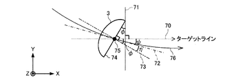
図17は、フェース角とクラブパス(入射角)を説明するための図である。図17には、XYZ座標系でZ軸の正側から視たXY平面上でのゴルフクラブ3(ヘッドのみ図示)が示されている。図17において、74はゴルフクラブ3のフェース面(打撃面)であり、75は打球点である。70は打球の目標方向を示すターゲットラインであり、71はターゲットライン70に直交する平面である。また、76はゴルフクラブ3のヘッドの軌跡を表す曲線であり、72は曲線76に対する打球点75での接線である。この時、フェース角φは平面71とフェース面74とのなす角であり、換言すれば、フェース面74と直交する直線73とターゲットライン70とのなす角である。また、クラブパス(入射角)ψは接線72(XY平面におけるヘッドが打球点75を通過する方向)とターゲットライン70とのなす角である。   FIG. 17 is a diagram for explaining the face angle and the club path (incident angle). FIG. 17 shows the golf club 3 (only the head is shown) on the XY plane viewed from the positive side of the Z axis in the XYZ coordinate system. In FIG. 17, reference numeral 74 denotes a face surface (striking surface) of the golf club 3, and 75 denotes a hitting point. Reference numeral 70 denotes a target line indicating the target direction of the hit ball, and reference numeral 71 denotes a plane orthogonal to the target line 70. Further, 76 is a curve representing the locus of the head of the golf club 3, and 72 is a tangent to the curve 76 at the hitting point 75. At this time, the face angle φ is an angle formed by the plane 71 and the face surface 74, in other words, an angle formed by the straight line 73 orthogonal to the face surface 74 and the target line 70. The club path (incident angle) ψ is an angle formed by the tangent line 72 (the direction in which the head passes the ball hitting point 75 in the XY plane) and the target line 70.

例えば、スイング解析部211は、ヘッドのフェース面とx軸方向とのなす角度が常に一定である(例えば、直交する)ものとして、インパクトの時刻timpactにおけるセンサーユニット10の姿勢から、フェース面に直交する直線の向きを計算する。そして、スイング解析部211は、当該直線の向きのZ軸成分を0としたものを直線73の向き
とし、直線73とターゲットライン70とのなす角(フェース角)φを計算する。
For example, the swing analysis unit 211 assumes that the angle formed by the face surface of the head and the x-axis direction is always constant (for example, orthogonal), and determines from the posture of the sensor unit 10 at the impact time t impact to the face surface. Calculate the direction of orthogonal straight lines. Then, the swing analysis unit 211 calculates the angle (face angle) φ formed by the straight line 73 and the target line 70 by setting the Z-axis component of the straight line direction to 0 as the straight line 73 direction.

また、例えば、スイング解析部211は、インパクトの時刻timpactにおけるヘッドの速度のZ軸成分を0とした速度(すなわち、XY平面におけるヘッドの速度)の向きを接線72の向きとし、接線72とターゲットライン70とのなす角(クラブパス(入射角))ψを計算する。 Further, for example, the swing analysis unit 211 sets the direction of the speed (that is, the speed of the head in the XY plane) where the Z-axis component of the head speed at impact time t impact is 0 as the direction of the tangent 72, An angle (club path (incident angle)) ψ formed with the target line 70 is calculated.

なお、フェース角φは、ヘッドの打球点75への入射方向と関係なく向きが固定されているターゲットライン70を基準とするフェース面74の傾きを表すため、絶対フェース角とも呼ばれる。これに対して、直線73と接線72とのなす角ηは、ヘッドの打球点75への入射方向を基準とするフェース面74の傾きを表すため、相対フェース角と呼ばれる。相対フェース角ηは、(絶対)フェース角φからクラブパス(入射角)ψを減算した角度である。   Note that the face angle φ is also referred to as an absolute face angle because it represents the inclination of the face surface 74 relative to the target line 70 whose direction is fixed regardless of the direction of incidence on the ball hitting point 75 of the head. On the other hand, the angle η formed by the straight line 73 and the tangent line 72 is referred to as a relative face angle because it represents the inclination of the face surface 74 with respect to the direction of incidence on the hitting point 75 of the head. The relative face angle η is an angle obtained by subtracting the club path (incident angle) ψ from the (absolute) face angle φ.

[アタック角の算出]
アタック角は、クラブパス(入射角)と同様、インパクト時刻timpactにおけるゴルフクラブ3のヘッドの軌道に基づく指標である。但し、アタック角は、軌道の角度をクラブパス(入射角)とは異なる平面において計算したものである。
[Calculation of attack angle]
The attack angle is an index based on the trajectory of the head of the golf club 3 at the impact time t impact as with the club path (incident angle). However, the attack angle is calculated by calculating the trajectory angle in a plane different from the club path (incident angle).

スイング解析部211は、インパクト時刻timpactにおけるヘッドの速度ベクトルとZ軸とがXZ平面でなす角を、アタック角として計算する。例えば、インパクト時刻timpactにおけるヘッドの移動方向がいわゆるアッパーブローの方向であるときに、アタック角は正の値となり、いわゆるダウンブローであるときにアタック角は負の値となり、いわゆるレベルブローの方向であるときにアタック角はゼロとなる。 The swing analysis unit 211 calculates an angle formed by the head velocity vector at the impact time t impact and the Z axis on the XZ plane as an attack angle. For example, when the head moving direction at the impact time t impact is a so-called upper blow direction, the attack angle is a positive value, and when the head is so-called down blow, the attack angle is a negative value, so-called level blow direction. The attack angle is zero when.

[スイングリズムの算出]
スイングリズムは、スイングの各区間の所要時間の比率を示す指標である。
[Swing rhythm calculation]
The swing rhythm is an index indicating the ratio of the required time of each section of the swing.

スイング解析部211は、例えば、スイング全体の期間を、スイング開始時刻tstart、ハーフウェイバック時刻tHWB、トップ時刻ttop、ハーフウェイダウン時刻tHWD、グリップ減速開始時刻tvmax、インパクト時刻timpactで区切ることにより、スイング全体の期間を複数の区間に分割し、各区間の所要時間を計算する。 For example, the swing analysis unit 211 determines the period of the entire swing as follows: swing start time t start , half way back time t HWB , top time t top , half way down time t HWD , grip deceleration start time t vmax , impact time t impact Is divided into a plurality of sections, and the required time for each section is calculated.

そして、スイング解析部211は、互いに異なる2つの区間の所要時間の比率を、スイングリズムとして計算する。互いに異なる2つの区間は、互いに重複しない2つの区間であってもよいし、一方が他方を包含する関係を有する2つの区間であってもよい。また、互いに異なる2つの区間は、ユーザー2によって予め指定された2つの区間であってもよい。   Then, the swing analysis unit 211 calculates a ratio of required times of two different sections as a swing rhythm. Two sections that are different from each other may be two sections that do not overlap each other, or may be two sections that have a relationship in which one includes the other. Further, the two sections different from each other may be two sections designated in advance by the user 2.

例えば、スイング解析部211は、バックスイングの所要時間(スイング開始時刻tstartからトップ時刻ttopまでの区間の所要時間)を、ダウンスイングの所要時間(トップ時刻ttopからインパクト時刻timpactまでの区間の所要時間)で除してできる比率を、スイングリズムとして計算する。 For example, the swing analysis unit 211 calculates the time required for the back swing (the time required for the section from the swing start time t start to the top time t top ) and the time required for the down swing (from the top time t top to the impact time t impact ). The ratio obtained by dividing by the required time of the section is calculated as a swing rhythm.

[ハンドアップ角の算出]
ハンドアップ角は、スイング開始時刻tstartとインパクト時刻timpactとの間におけるシャフトの姿勢ずれを示す指標の1つであって、スイング開始時刻tstartにおけるシャフトのライ角方向の傾斜角α(tstart)と、インパクト時刻timpactにおけるシャフトのライ角方向の傾斜角α(timpact)とのずれを示す指標である。なお、スイング開始時刻tstartにおけるシャフトのライ角方向の傾斜
角α(tstart)の代わりに、アドレス時刻taddressにおけるシャフトのライ角方向の傾斜角α(taddress)を用いることもできる。また、ライ角方向の傾斜角αとは、図10において符号αで示した角度のことであって、YZ平面においてy軸とY軸とが成す角度である。
[Calculation of hand-up angle]
The hand-up angle is one of the indexes indicating the shaft posture deviation between the swing start time t start and the impact time t impact, and is an inclination angle α (t in the lie angle direction of the shaft at the swing start time t start . start ) and an inclination angle α (t impact ) in the lie angle direction of the shaft at the impact time t impact . Instead of the inclination angle α (t start ) in the lie angle direction of the shaft at the swing start time t start , the inclination angle α (t address ) in the lie angle direction of the shaft at the address time t address can also be used. In addition, the inclination angle α in the lie angle direction is an angle indicated by a symbol α in FIG. 10, and is an angle formed by the y axis and the Y axis in the YZ plane.

スイング解析部211は、例えば、スイング開始時刻tstartにおけるゴルフクラブ3の姿勢(グローバル座標で表された姿勢)に基づき、スイング開始時における傾斜角α(tstart)を算出する。 For example, the swing analysis unit 211 calculates the tilt angle α (t start ) at the start of the swing based on the posture of the golf club 3 at the swing start time t start (the posture represented by the global coordinates).

また、スイング解析部211は、例えば、インパクト時刻timpactにおけるゴルフクラブ3の姿勢(グローバル座標で表された姿勢)に基づき、インパクト時刻timpactにおける傾斜角α(timpact)を算出する。 In addition, the swing analysis unit 211 calculates an inclination angle α (t impact ) at the impact time t impact based on, for example, the posture of the golf club 3 at the impact time t impact (posture expressed in global coordinates).

また、スイング解析部211は、例えば、アドレス時刻taddressにおけるz軸加速度成分aとy軸加速度成分aとの比(a/a)に基づき、アドレス時刻taddressにおける傾斜角α(taddress)を算出する。なお、スイング解析部211は、y軸加速度成分aを式(1)における「y(0)」へ当てはめることでアドレス時刻における傾斜角α(taddress)を求めることもできる。 Further, the swing analysis unit 211, for example, based on the ratio of the z-axis acceleration component a z and y-axis acceleration component a y in the address time t address (a y / a z ), the tilt angle in the address time t address alpha ( t address ) is calculated. Note that the swing analysis unit 211 can also obtain the tilt angle α (t address ) at the address time by applying the y-axis acceleration component a y to “y (0)” in Expression (1).

また、スイング解析部211は、例えば、インパクト時刻timpactにおける傾斜角α(timpact)からスイング開始時刻tstartにおける傾斜角α(tstart)を減算することにより、ハンドアップ角Δα=α(timpact)−α(tstart)を算出する。 Further, the swing analysis unit 211 subtracts the inclination angle α (t start ) at the swing start time t start from the inclination angle α (t impact ) at the impact time t impact , for example, to thereby determine the hand-up angle Δα = α (t impact ) −α (t start ).

また、スイング解析部211は、例えば、インパクト時刻timpactにおける傾斜角α(timpact)からアドレス時刻taddressにおける傾斜角α(taddress)を減算することにより、ハンドアップ角Δα=α(timpact)−α(taddress)を算出してもよい。 In addition, the swing analysis unit 211 subtracts the inclination angle α (t address ) at the address time t address from the inclination angle α (t impact ) at the impact time t impact , for example, so that the hand-up angle Δα = α (t impact). ) -Α (t address ) may be calculated.

[トップ時のシャフト軸回転角の算出]
トップ時のシャフト軸回転角θtopは、基準となるタイミングからトップのタイミングまでにゴルフクラブ3がシャフト軸回りに回転した角度(相対回転角)である。基準となるタイミングは、例えば、バックスイング開始時又はアドレス時である。本実施形態では、ユーザー2が右打ちの場合は、ゴルフクラブ3のヘッド側に先端を向けた右ねじの締め方向(グリップエンド側からヘッド側を視たときに時計回りの方向)をシャフト軸回転角θtopの正方向とする。逆に、ユーザー2が左打ちの場合は、ゴルフクラブ3のヘッド側に先端を向けた左ねじの締め方向(グリップエンド側からヘッド側を視たときに反時計回りの方向)をシャフト軸回転角θtopの正方向とする。
[Calculation of shaft rotation angle at top]
The shaft shaft rotation angle θ top at the time of top is an angle (relative rotation angle) that the golf club 3 rotates around the shaft axis from the reference timing to the top timing. The reference timing is, for example, at the start of backswing or at the time of addressing. In this embodiment, when the user 2 is right-handed, the tightening direction of the right screw with the tip directed to the head side of the golf club 3 (the clockwise direction when viewing the head side from the grip end side) is the shaft axis. A positive direction of the rotation angle θ top is assumed. Conversely, when the user 2 is left-handed, the shaft is rotated in the direction of tightening the left screw with the tip facing the golf club 3 head side (counterclockwise when viewing the head side from the grip end side). The positive direction of the angle θ top is assumed.

図18は、スイング開始(バックスイング開始)からインパクトまでのシャフト軸回転角の時間変化の一例を示す図である。図18において、横軸は時間(s)、縦軸はシャフト軸回転角(deg)である。図18には、スイング開始時(バックスイング開始時)を基準のタイミング(シャフト軸回転角が0°)としたトップ時のシャフト軸回転角θtopが示されている。 FIG. 18 is a diagram illustrating an example of a temporal change in the shaft shaft rotation angle from the swing start (back swing start) to the impact. In FIG. 18, the horizontal axis represents time (s), and the vertical axis represents the shaft axis rotation angle (deg). FIG. 18 shows the shaft shaft rotation angle θ top at the top when the swing start time (back swing start time) is the reference timing (the shaft shaft rotation angle is 0 °).

本実施形態では、図3に示したように、センサーユニット10のy軸がゴルフクラブ3のシャフトの長手方向(ゴルフクラブ3の長手方向)にほぼ一致している。従って、例えば、スイング解析部211は、スイング開始の時刻tstart(バックスイング開始時)又はアドレス時からトップの時刻ttop(トップ時)まで、角速度データに含まれるy軸角速度を時間積分することで、シャフト軸回転角θtopを計算する。同様に、スイ
ング解析部211は、スイング開始の時刻tstart(バックスイング開始時)又はアドレス時からハーフウェイバック時刻tHWBまで、角速度データに含まれるy軸角速度を時間積分することで、ハーフウェイバック時刻tHWBにおけるシャフト軸回転角θHWBを計算する。
In the present embodiment, as shown in FIG. 3, the y-axis of the sensor unit 10 substantially coincides with the longitudinal direction of the golf club 3 (longitudinal direction of the golf club 3). Accordingly, for example, the swing analysis unit 211 time-integrates the y-axis angular velocity included in the angular velocity data from the swing start time t start (backswing start time) or from the address time to the top time t top (top time). Then, the shaft shaft rotation angle θ top is calculated. Similarly, the swing analysis unit 211 time-integrates the y-axis angular velocity included in the angular velocity data from the swing start time t start (at the start of the back swing) or from the address time to the half way back time t HWB , thereby performing the half way The shaft shaft rotation angle θ HWB at the back time t HWB is calculated.

[グリップ減速率及びグリップ減速時間率の算出]
グリップ減速率は、グリップの減速量に基づく指標であり、ダウンスイング中にグリップが減速し始めるときのグリップの速度と、インパクトのときのグリップの速度との比である。また、グリップ減速時間率は、グリップの減速期間に基づく指標であり、ダウンスイング中にグリップが減速し始めてからインパクトまでの時間と、ダウンスイングの時間との比である。グリップの速度は、ユーザー2が把持している部分の速度であることが望ましいが、グリップの任意の部分(例えば、グリップエンド)の速度であってもよいし、グリップ付近の部分の速度であってもよい。
[Calculation of grip deceleration rate and grip deceleration time rate]
The grip deceleration rate is an index based on the amount of deceleration of the grip, and is a ratio between the grip speed when the grip starts to decelerate during the downswing and the grip speed at the time of impact. The grip deceleration time rate is an index based on the grip deceleration period, and is a ratio between the time from the start of deceleration of the grip during the downswing to the impact and the time of the downswing. The grip speed is preferably the speed of the part gripped by the user 2, but may be the speed of any part of the grip (for example, the grip end) or the speed of the part near the grip. May be.

図19は、ダウンスイングにおけるグリップの速度の時間変化の一例を示す図である。図19において、横軸は時間(s)、縦軸はグリップの速度(m/s)である。図19において、グリップが減速を開始するときのグリップの速度(グリップの最大速度)をV1、インパクトのときのグリップの速度をV2とすると、グリップ減速率R(単位:%)は、次の式(16)で表される。 FIG. 19 is a diagram illustrating an example of a temporal change in the grip speed in the downswing. In FIG. 19, the horizontal axis represents time (s), and the vertical axis represents grip speed (m / s). In FIG. 19, when the grip speed when the grip starts to decelerate (maximum grip speed) is V1, and the grip speed at the time of impact is V2, the grip deceleration rate R V (unit:%) is It is represented by Formula (16).

Figure 2017124074
また、図19において、トップからグリップが減速を開始するまでの時間をT1、グリップが減速を開始してからインパクトまでの時間をT2とすると、グリップ減速時間率R(単位:%)は、次の式(17)で表される。
Figure 2017124074
In FIG. 19, when the time from the top until the grip starts to decelerate is T1, and the time from when the grip starts decelerating to the impact is T2, the grip deceleration time rate R T (unit:%) is It is represented by the following formula (17).

Figure 2017124074
例えば、ユーザー2がゴルフクラブ3を把持する部分の近くにセンサーユニット10が取り付けられるものとして、センサーユニット10の速度をグリップの速度とみなしてもよい。従って、まず、スイング解析部211は、トップの時刻ttopからインパクトの時刻timpactまで(ダウンスイング中)の各時刻tにおけるセンサーユニット10の位置の座標とその1つ前の時刻におけるセンサーユニット10の位置の座標との差分により、各時刻tにおけるセンサーユニット10の速度を計算する。
Figure 2017124074
For example, assuming that the sensor unit 10 is attached near the portion where the user 2 holds the golf club 3, the speed of the sensor unit 10 may be regarded as the grip speed. Therefore, first, the swing analysis unit 211 detects the coordinates of the position of the sensor unit 10 at each time t from the top time t top to the impact time t impact (during the downswing) and the sensor unit 10 at the previous time. The speed of the sensor unit 10 at each time t is calculated based on the difference from the coordinates of the position.

次に、スイング解析部211は、各時刻tにおけるセンサーユニット10の速度の大きさを計算し、その最大値をV1、インパクトの時刻timpactにおける速度の大きさをV2とする。また、スイング解析部211は、センサーユニット10の速度の大きさが最大値V1となる時刻tvmaxを特定する。さらに、スイング解析部211は、T1=tvmax−ttop、T2=timpact−tvmaxを計算する。そして、スイング解析部211は、式(16),式(17)により、それぞれグリップ減速率R,グリップ減速時間率Rを計算する。 Next, the swing analysis unit 211 calculates the magnitude of the speed of the sensor unit 10 at each time t, and sets the maximum value as V1 and the magnitude of the speed at the impact time timpact as V2. In addition, the swing analysis unit 211 specifies a time tvmax when the magnitude of the speed of the sensor unit 10 becomes the maximum value V1. Further, the swing analysis unit 211 calculates T1 = t vmax −t top and T2 = t impact −t vmax . Then, the swing analysis unit 211 calculates the grip deceleration rate R V and the grip deceleration time rate RT according to the equations (16) and (17), respectively.

なお、スイング解析部211は、グリップエンドの速度をグリップの速度とみなし、ダウンスイング中)の各時刻tにおけるグリップエンドの位置の座標に基づき、グリップエンドの速度を計算し、上記と同様の計算により、グリップ減速率R及びグリップ減速時
間率Rを求めてもよい。
The swing analysis unit 211 regards the grip end speed as the grip speed and calculates the grip end speed based on the coordinates of the position of the grip end at each time t (during the downswing), and the same calculation as above. Thus, the grip deceleration rate RV and the grip deceleration time rate RT may be obtained.

[「Vゾーン」項目の指標の算出]
スイング解析部211は、ハーフウェイバック時刻tHWBにヘッド位置の属していた領域と、ハーフウェイダウン時刻tHWDにヘッド位置の属していた領域と、グリップ減速開始時刻tvmaxにヘッド位置の属していた領域と、トップ時刻ttopにヘッド位置の属していた領域とを、指標として算出する。複数の領域の境界は、ユーザー2のアドレス姿勢によって決まる仮想面であるシャフトプレーンSP及びホーガンプレーンHP(Vゾーン)に基づいて決定される。
[Calculation of "V zone" item index]
The swing analysis unit 211 has a head position at halfway back time t HWB , a head position at halfway down time t HWD, and a head position at grip deceleration start time tvmax. And the area to which the head position belonged at the top time t top is calculated as an index. The boundaries of the plurality of areas are determined based on the shaft plane SP and Hogan plane HP (V zone), which are virtual planes determined by the address posture of the user 2.

図20は、シャフトプレーンSP及びホーガンプレーンHP(Vゾーン)と複数の領域との関係の一例を示す図である(なお、図20の下部には、シャフトプレーンSP及びホーガンプレーンHPとユーザー2の姿勢との概略の一例を示した。)。図20は、X軸の負側から視た(YZ平面に投影した)場合の、シャフトプレーンSP、ホーガンプレーンHP及び5つの領域A〜Eの関係を示している。領域Bは、ホーガンプレーンHPを含む所定の空間であり、領域Dは、シャフトプレーンSPを含む所定の空間である。領域Cは、領域Bと領域Dとに挟まれている空間(領域Bとの境界面SBCと領域Dとの境界面SCDとの間の空間)である。領域Aは、領域Cと反対側の境界面SABで領域Bと接する空間である。領域Eは、領域Cと反対側の境界面SDEで領域Dと接する空間である。 FIG. 20 is a diagram showing an example of the relationship between the shaft plane SP and Hogan plane HP (V zone) and a plurality of regions (note that the lower part of FIG. 20 shows the shaft plane SP and Hogan plane HP and the user 2 An example of the outline of the posture was shown.) FIG. 20 shows the relationship between the shaft plane SP, the Hogan plane HP, and the five areas A to E when viewed from the negative side of the X axis (projected on the YZ plane). The region B is a predetermined space including the Hogan plane HP, and the region D is a predetermined space including the shaft plane SP. Region C is a space (the space between the boundary surface S CD between the boundary surface S BC and region D of the region B) which is sandwiched between the regions B and D. The region A is a space in contact with the region B at the boundary surface S AB opposite to the region C. The region E is a space in contact with the region D at the boundary surface SDE opposite to the region C.

境界面SAB、境界面SBC、境界面SCD及び境界面SDEの設定方法は、種々考えられる。一例を挙げると、YZ平面上において、ホーガンプレーンHPが境界面SABと境界面SBCのちょうど真ん中になり、かつ、シャフトプレーンSPが境界面SCDと境界面SDEのちょうど真ん中になり、かつ、領域B、領域C、領域Dの原点O(X軸)周りの角度が等しくなるように設定することができる。すなわち、シャフトプレーンSPとホーガンプレーンHPとのなす第1角度βに対して、ホーガンプレーンHPと境界面SAB及び境界面SBCとのなす角をそれぞれβ/4に設定し、シャフトプレーンSPと境界面SCD及び境界面SDEとのなす角をそれぞれβ/4に設定すれば、領域B、領域C、
領域Dの角度がともにβ/2に設定される。
Various methods for setting the boundary surface S AB , the boundary surface S BC , the boundary surface S CD, and the boundary surface S DE are conceivable. For example, on the YZ plane, the Hogan plane HP is exactly in the middle of the boundary surface S AB and the boundary surface S BC , and the shaft plane SP is in the middle of the boundary surface S CD and the boundary surface S DE . In addition, the angles around the origin O (X axis) of the regions B, C, and D can be set to be equal. That is, with respect to the first angle β formed by the shaft plane SP and the Hogan plane HP, the angles formed by the Hogan plane HP, the boundary surface SAB, and the boundary surface SBC are respectively set to β / 4. If the angles formed by S CD and boundary surface S DE are respectively set to β / 4, region B, region C,
Both angles of the region D are set to β / 2.

なお、ハーフウェイバック時やハーフウェイダウン時のヘッド位置のY座標が負となるようなスイングは想定できないので、図20では、領域Aの境界面SABと反対側の境界面はXZ平面に設定されている。同様に、ハーフウェイバック時やハーフウェイダウン時のヘッド位置のZ座標が負となるようなスイングは想定できないので、領域Eの境界面SDEと反対側の境界面はXY平面に設定されている。もちろん、領域Aや領域Eの原点O(X軸)周りの角度も領域B、領域C、領域Dと等しくなるように、領域Aや領域Eの境界面を設定してもよい。 Since it is not possible to assume a swing in which the Y coordinate of the head position is negative during halfway back or halfway down, in FIG. 20, the boundary surface opposite to the boundary surface S AB in the region A is the XZ plane. Is set. Similarly, the Z-coordinate of the head position at the half-way back or during Halfway down swing such that negative can not be assumed, the boundary surface between the boundary surface S DE region E opposite side is set to the XY plane Yes. Of course, the boundary surfaces of the regions A and E may be set so that the angles around the origin O (X axis) of the regions A and E are also equal to the regions B, C, and D.

具体的には、まず、スイング解析部211は、シャフトプレーンSPの4つの頂点U1,U2,S1,S2の各座標及びホーガンプレーンHPの4つの頂点U1,U2,H1,H2の各座標に基づき、領域A〜Eの各境界面SAB、境界面SBC、境界面SCD及び境界面SDEを設定する。 Specifically, first, the swing analysis unit 211 is based on the coordinates of the four vertices U1, U2, S1, and S2 of the shaft plane SP and the coordinates of the four vertices U1, U2, H1, and H2 of the Hogan plane HP. , Each boundary surface S AB , boundary surface S BC , boundary surface S CD and boundary surface S DE of the regions A to E are set.

次に、スイング解析部211は、ハーフウェイバック時刻tHWBのヘッド位置の座標、ハーフウェイダウン時刻tHWDのヘッド位置の座標、グリップ減速開始時刻tvmaxのヘッドの位置の座標、トップ時刻ttopのヘッドの位置の座標がそれぞれ領域A〜Eのいずれに属するかを判定する。 Then, the swing analysis unit 211, the coordinates of the head position of the half-way back time t HWB, the coordinates of the head position of the half-way down the time t HWD, coordinates of the position of the head of the grip deceleration starting time t vmax, top time t top It is determined which of the areas A to E each of the head position coordinates belongs to.

[スイング解析処理の手順]
図21は、処理部21によるスイング解析処理の手順の一例を示すフローチャート図で
ある。処理部21は、記憶部24に記憶されているスイング解析プログラム240を実行することにより、例えば、図21のフローチャートの手順でスイング解析処理を実行する。以下、図21のフローチャートについて説明する。
[Swing analysis procedure]
FIG. 21 is a flowchart illustrating an example of a procedure of swing analysis processing by the processing unit 21. The processing unit 21 executes the swing analysis program 240 stored in the storage unit 24, thereby executing the swing analysis process, for example, according to the procedure shown in the flowchart of FIG. Hereinafter, the flowchart of FIG. 21 will be described.

まず、処理部21は、ユーザー2による計測開始操作(図4のステップS2の操作)が行われるまで待機し(S10のN)、計測開始操作が行われると(S10のY)、センサーユニット10に計測開始コマンドを送信し、センサーユニット10から計測データの取得を開始する(S12)。   First, the processing unit 21 waits until a measurement start operation (operation in step S2 in FIG. 4) by the user 2 is performed (N in S10). When the measurement start operation is performed (Y in S10), the sensor unit 10 A measurement start command is transmitted to the sensor unit 10, and acquisition of measurement data from the sensor unit 10 is started (S12).

次に、処理部21は、ユーザー2にアドレス姿勢をとるように指示する(S14)。ユーザー2は、この指示に従い、アドレス姿勢をとって静止する(図4のステップS4)。   Next, the processing unit 21 instructs the user 2 to take an address posture (S14). In accordance with this instruction, the user 2 takes an address posture and stops (step S4 in FIG. 4).

次に、処理部21は、センサーユニット10から取得した計測データを用いてゴルフクラブ3が正しい姿勢で所定期間に亘って静止したか否かを判定(S16)し、静止した場合(S16Y)に、ユーザー2へスイング開始の許可を通知し(S18)、そうでない場合は、終了判定処理(S24)へ移行する。なお、処理部21は、例えば、所定の音を出力し、あるいは、センサーユニット10にLEDを設けておいて当該LEDを点灯させる等して、ユーザー2にスイング開始の許可を通知し、ユーザー2は、この通知を確認した後にスイング動作(図4のステップS6の動作)を開始する。   Next, the processing unit 21 determines whether or not the golf club 3 is stationary in a correct posture for a predetermined period using the measurement data acquired from the sensor unit 10 (S16), and when it is stationary (S16Y). The user 2 is notified of permission to start the swing (S18). Otherwise, the process proceeds to the end determination process (S24). For example, the processing unit 21 outputs a predetermined sound or notifies the user 2 of permission to start swinging by providing an LED in the sensor unit 10 and lighting the LED. Starts the swing operation (the operation in step S6 in FIG. 4) after confirming this notification.

次に、処理部21は、センサーユニット10から取得した計測データに基づきスイングの許可(S18)から所定期間内にインパクトを検出したか否かを判定し(S20)、検出した場合(S20Y)には、スイング解析データの生成処理(S22)へ移行し、そうでない場合(S20N)には、終了判定処理(S24)へ移行する。   Next, the processing unit 21 determines whether or not an impact is detected within a predetermined period from the permission of the swing (S18) based on the measurement data acquired from the sensor unit 10 (S20), and if it is detected (S20Y). Shifts to the swing analysis data generation process (S22), otherwise shifts to the end determination process (S24).

次に、処理部21は、センサーユニット10から取得した計測データからインパクト前後におけるスイング中の計測データを抽出し、当該スイング中の計測データに基づき各種の指標及び軌跡を算出すると、当該指標及び軌跡を含むスイング解析データを生成してサーバー装置30へ送信する(S22)。なお、処理部21は、スイング中の計測データに関するバイアスの補正及びグローバル座標の設定に、ゴルフクラブ3が正しい姿勢で静止していた期間中の計測データを用いる。また、処理部21は、サーバー装置30へ送信するスイング解析データに対してスイング中の計測データ自体(いわゆる生データ)を含めてもよい。   Next, the processing unit 21 extracts the measurement data during the swing before and after the impact from the measurement data acquired from the sensor unit 10, and calculates various indexes and trajectories based on the measurement data during the swing. Is generated and transmitted to the server device 30 (S22). Note that the processing unit 21 uses measurement data during a period in which the golf club 3 is stationary in a correct posture for bias correction and global coordinate setting regarding measurement data during a swing. Further, the processing unit 21 may include the measurement data itself during swing (so-called raw data) with respect to the swing analysis data transmitted to the server device 30.

次に、処理部21は、ユーザー2による計測終了操作が行われたか否かを判定し(S24)、行われた場合(S24Y)にはフローを終了し、そうでない場合(S24N)には、アドレス指示処理(S14)へ移行する。   Next, the processing unit 21 determines whether or not a measurement end operation has been performed by the user 2 (S24), and if it has been performed (S24Y), the flow ends, and if not (S24N), The process proceeds to the address instruction process (S14).

なお、図21のフローチャートにおいて、可能な範囲で各工程の順番を適宜変えてもよいし、一部の工程を削除あるいは変更してもよいし、他の工程を追加してもよい。   In the flowchart of FIG. 21, the order of the steps may be appropriately changed within a possible range, some of the steps may be deleted or changed, and other steps may be added.

1−4.サーバー装置の構成
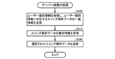
図22は、サーバー装置30の構成例を示す図である。図22に示すように、本実施形態では、サーバー装置30は、処理部31、通信部32及び記憶部34を含んで構成されている。ただし、サーバー装置30は、適宜、これらの構成要素の一部が削除又は変更され、あるいは、他の構成要素が付加された構成であってもよい。
1-4. Configuration of Server Device FIG. 22 is a diagram illustrating a configuration example of the server device 30. As shown in FIG. 22, in the present embodiment, the server device 30 includes a processing unit 31, a communication unit 32, and a storage unit 34. However, the server device 30 may have a configuration in which some of these components are appropriately deleted or changed, or other components are added as appropriate.

記憶部34は、例えば、ROMやフラッシュROM、RAM等の各種ICメモリーやハードディスクやメモリーカードなどの記録媒体等により構成される。記憶部34は、処理部31が各種の計算処理や制御処理を行うためのプログラムや、アプリケーション機能を
実現するための各種プログラムやデータ等を記憶している。
The storage unit 34 includes, for example, various IC memories such as a ROM, a flash ROM, and a RAM, a recording medium such as a hard disk and a memory card, and the like. The storage unit 34 stores programs for the processing unit 31 to perform various calculation processes and control processes, various programs and data for realizing application functions, and the like.

本実施形態では、記憶部34には、スイング解析装置20が生成した複数のスイング解析データ248を含むスイング解析データリスト341が記憶(保存)されている。すなわち、スイング解析装置20の処理部21がユーザー2のスイング動作を解析する毎に生成したスイング解析データ248は、順次、スイング解析データリスト341に追加される。   In the present embodiment, the storage unit 34 stores (saves) a swing analysis data list 341 including a plurality of swing analysis data 248 generated by the swing analysis device 20. That is, the swing analysis data 248 generated every time the processing unit 21 of the swing analysis device 20 analyzes the swing motion of the user 2 is sequentially added to the swing analysis data list 341.

また、記憶部34は、処理部31の作業領域として用いられ、処理部31が各種プログラムに従って実行した演算結果等を一時的に記憶する。さらに、記憶部34は、処理部31の処理により生成されたデータのうち、長期的な保存が必要なデータを記憶してもよい。   The storage unit 34 is used as a work area of the processing unit 31 and temporarily stores calculation results and the like executed by the processing unit 31 according to various programs. Furthermore, the storage unit 34 may store data that needs to be stored for a long time among the data generated by the processing of the processing unit 31.

通信部32は、ネットワーク40を介してスイング解析装置20の通信部27(図9参照)との間でデータ通信を行うものである。例えば、通信部32は、スイング解析装置20の通信部27からスイング解析データ248を受け取って、処理部31に送る処理を行う。また、例えば、通信部32は、図7の選択画面の表示に必要な情報をスイング解析装置20の通信部27に送信する処理や、図7の選択画面における選択情報をスイング解析装置20の通信部27から受信して処理部31に送る処理を行う。また、例えば、通信部32は、図8の表示画面の表示に必要な情報を処理部31から受け取ってスイング解析装置20の通信部27に送信する処理を行う。   The communication unit 32 performs data communication with the communication unit 27 (see FIG. 9) of the swing analysis device 20 via the network 40. For example, the communication unit 32 performs a process of receiving the swing analysis data 248 from the communication unit 27 of the swing analysis device 20 and sending it to the processing unit 31. Further, for example, the communication unit 32 transmits information necessary for display of the selection screen of FIG. 7 to the communication unit 27 of the swing analysis device 20, or transmits selection information on the selection screen of FIG. 7 to the communication of the swing analysis device 20. The processing received from the unit 27 and sent to the processing unit 31 is performed. Further, for example, the communication unit 32 performs processing for receiving information necessary for displaying the display screen of FIG. 8 from the processing unit 31 and transmitting the information to the communication unit 27 of the swing analysis apparatus 20.

処理部31は、各種プログラムに従い、通信部32を介してスイング解析装置20からスイング解析データ248を受信して、記憶部34に記憶させる(スイング解析データリスト341に追加する)処理を行う。また、処理部31は、各種プログラムに従い、通信部32を介して、スイング解析装置20から各種の情報を受信し、各種の画面(図7、図8の各画面等)の表示に必要な情報をスイング解析装置20に送信する処理等を行う。また、処理部31は、その他の各種の制御処理を行う。   The processing unit 31 receives the swing analysis data 248 from the swing analysis device 20 via the communication unit 32 and stores it in the storage unit 34 (added to the swing analysis data list 341) according to various programs. Further, the processing unit 31 receives various types of information from the swing analysis apparatus 20 via the communication unit 32 in accordance with various programs, and information necessary for displaying various screens (the respective screens in FIGS. 7 and 8, etc.). Is transmitted to the swing analysis device 20. The processing unit 31 performs other various control processes.

特に、本実施形態では、処理部31は、所定のプログラムを実行することにより、データ取得部310、記憶処理部312として機能する。   In particular, in the present embodiment, the processing unit 31 functions as the data acquisition unit 310 and the storage processing unit 312 by executing a predetermined program.

データ取得部310は、通信部32がスイング解析装置20から受信したスイング解析データ248を受け取って記憶処理部312に送る処理を行う。   The data acquisition unit 310 performs processing for receiving the swing analysis data 248 received by the communication unit 32 from the swing analysis device 20 and sending it to the storage processing unit 312.

記憶処理部312は、記憶部34に対する各種プログラムや各種データのリード/ライト処理を行う。例えば、記憶処理部312は、データ取得部310からスイング解析データ248を受け取り、記憶部34に記憶させる(スイング解析データリスト341に追加する)処理や、記憶部34に記憶されているスイング解析データリスト341からスイング解析データ248を読み出す処理等を行う。   The storage processing unit 312 performs read / write processing of various programs and various data for the storage unit 34. For example, the storage processing unit 312 receives the swing analysis data 248 from the data acquisition unit 310 and stores it in the storage unit 34 (adds it to the swing analysis data list 341), or the swing analysis data stored in the storage unit 34. Processing such as reading the swing analysis data 248 from the list 341 is performed.

1−5.サーバー装置の処理
サーバー装置30の処理部31は、スイング解析装置20との間でデータの送受信を行い、ユーザーのスイング解析データをユーザーごとに管理する。
1-5. Processing of Server Device The processing unit 31 of the server device 30 transmits / receives data to / from the swing analysis device 20 and manages user swing analysis data for each user.

[サーバー装置の処理の手順]
図23は、サーバー装置の処理と関連するスイング解析装置20の処理部21による処理の手順の一例を示すフローチャート図である。また、図24は、サーバー装置の処理の手順の一例を示すフローチャート図である。サーバー装置30の処理部31(コンピューターの一例)は、記憶部34に記憶されているプログラムを実行することにより、例えば
、図24のフローチャートの手順で処理を実行する。以下、図23及び図24のフローチャートについて説明する。
[Processing procedure of server device]
FIG. 23 is a flowchart illustrating an example of a processing procedure performed by the processing unit 21 of the swing analysis device 20 related to the processing of the server device. FIG. 24 is a flowchart showing an example of the processing procedure of the server apparatus. The processing unit 31 (an example of a computer) of the server device 30 executes the program according to the procedure of the flowchart of FIG. 24 by executing the program stored in the storage unit 34, for example. Hereinafter, the flowcharts of FIGS. 23 and 24 will be described.

まず、スイング解析装置20の処理部21は、サーバー装置30に、ユーザー2に割り当てられたユーザー識別情報を送信する(図23のS100)。   First, the processing unit 21 of the swing analysis device 20 transmits the user identification information assigned to the user 2 to the server device 30 (S100 in FIG. 23).

次に、サーバー装置30の処理部31は、ユーザー識別情報を受信し、ユーザー識別情報に対応するスイング解析データ248の一覧情報を送信する(図24のS200)。   Next, the processing unit 31 of the server device 30 receives the user identification information and transmits the list information of the swing analysis data 248 corresponding to the user identification information (S200 in FIG. 24).

次に、スイング解析装置20の処理部21は、スイング解析データ248の一覧情報を受信し、表示部25にスイング解析データの選択画面(図7)を表示させる(図23のS110)。   Next, the processing unit 21 of the swing analysis device 20 receives the list information of the swing analysis data 248 and causes the display unit 25 to display a selection screen of swing analysis data (FIG. 7) (S110 in FIG. 23).

そして、スイング解析装置20の処理部21は、スイング解析データの選択画面においてスイング解析データ248が選択されるまで待機し(図23のS120のN)、選択されると(図23のS120のY)、サーバー装置30にスイング解析データの選択情報を送信する(図23のS130)。   Then, the processing unit 21 of the swing analysis device 20 waits until the swing analysis data 248 is selected on the swing analysis data selection screen (N in S120 in FIG. 23), and when selected (Y in S120 in FIG. 23). ), The swing analysis data selection information is transmitted to the server device 30 (S130 in FIG. 23).

次に、サーバー装置30の処理部31は、スイング解析データの選択情報を受信する(図24のS210)。   Next, the processing unit 31 of the server device 30 receives the selection information of the swing analysis data (S210 in FIG. 24).

次に、サーバー装置30の処理部31は、選択されたスイング解析データを送信する(図24のS240)。   Next, the processing unit 31 of the server device 30 transmits the selected swing analysis data (S240 in FIG. 24).

次に、スイング解析装置20の処理部21は、選択されたスイング解析データを受信し、スイング解析データに基づく画像(各種の指標を示す画像、スイングの軌跡を示す画像など)を表示部25に表示させ(図23のS140)、処理を終了する。   Next, the processing unit 21 of the swing analysis device 20 receives the selected swing analysis data, and displays images (images showing various indices, images showing swing trajectories, etc.) based on the swing analysis data on the display unit 25. It is displayed (S140 in FIG. 23), and the process is terminated.

なお、図23のフローチャートにおいて、可能な範囲で各工程の順番を適宜変えてもよいし、一部の工程を削除あるいは変更してもよいし、他の工程を追加してもよい。同様に、図24のフローチャートにおいて、可能な範囲で各工程の順番を適宜変えてもよいし、一部の工程を削除あるいは変更してもよいし、他の工程を追加してもよい。   In the flowchart of FIG. 23, the order of each process may be appropriately changed within a possible range, a part of the process may be deleted or changed, and another process may be added. Similarly, in the flowchart of FIG. 24, the order of each process may be appropriately changed within a possible range, a part of the process may be deleted or changed, and another process may be added.

1−6.スイング解析装置の静止判定について
1−6−1.静止判定の概要
図21に示したとおり、本実施形態のスイング解析装置20は、計測開始操作後(S10Y)、ゴルフクラブ3が静止した(静止状態である)と判定した場合(S16Y)にゴルフクラブ3によるスイング開始の許可をユーザー2に通知し(S18)、静止したと判定しない場合(S16N)にスイング開始の許可をユーザー2に通知しない。具体的には、本実施形態のスイング解析装置20は、ゴルフクラブ3の姿勢が不安定である場合、又は、ゴルフクラブ3の姿勢が標準的なアドレスの姿勢から著しく外れている場合は、スイング開始の許可をユーザー2に通知しない。
1-6. About stationary determination of swing analysis device 1-6-1. Overview of Stillness Determination As shown in FIG. 21, the swing analysis apparatus 20 of the present embodiment performs golf when it is determined that the golf club 3 is stationary (in a stationary state) after the measurement start operation (S10Y) (S16Y). The user 2 is notified of the permission to start the swing by the club 3 (S18), and the user 2 is not notified of the permission to start the swing if it is not determined to be stationary (S16N). Specifically, the swing analysis device 20 according to the present embodiment performs the swing when the posture of the golf club 3 is unstable or when the posture of the golf club 3 is significantly different from the posture of the standard address. The user 2 is not notified of permission to start.

しかし、ユーザー2がアドレス姿勢をとって静止した場合であっても、スイング開始の許可が通知されない場合がある。その原因は、以下の原因(1)又は原因(2)と考えられる。   However, even when the user 2 takes an address posture and stands still, permission to start swing may not be notified. The cause is considered to be the following cause (1) or cause (2).

(1)スイング解析装置20にインストールされているスイング解析アプリケーション又はセンサーユニット10が故障している。   (1) The swing analysis application or sensor unit 10 installed in the swing analysis device 20 is out of order.

(2)ユーザー2は正しい姿勢で静止しているつもりであってもスイング解析装置20によって静止と判定されるための条件をゴルフクラブ3が満たしていない。   (2) Even if the user 2 intends to stand still in the correct posture, the golf club 3 does not satisfy the condition for the swing analysis device 20 to determine that the user 2 is stationary.

このうち、原因(1)の場合は、センサーユニット10の修理又はスイング解析アプリケーションの修理(再インストールなど)を行う必要があるが、原因(2)の場合は、修理の必要はなく、ユーザー2がアドレス姿勢を調整すればよいだけである。   Of these, in the case of cause (1), it is necessary to repair the sensor unit 10 or the swing analysis application (reinstallation, etc.), but in the case of cause (2), there is no need for repair. It is only necessary to adjust the address attitude.

しかし、本当の原因が(1)、(2)の何れであるのかをユーザー2自身が判別することは難しい。このため、原因が(2)であるにもかかわらずセンサーユニット10の製造者又はスイング解析アプリケーションの提供者(例えばサーバー装置30の運営者)へユーザー2が修理依頼をしたり、原因が(1)であるにもかかわらずアドレス姿勢の改善をユーザー2が何度も試みて時間が浪費されたり、といった問題が生じていた。   However, it is difficult for the user 2 to determine whether the real cause is (1) or (2). Therefore, even though the cause is (2), the user 2 makes a repair request to the manufacturer of the sensor unit 10 or the provider of the swing analysis application (for example, the operator of the server device 30) or the cause is (1). However, the user 2 has repeatedly tried to improve the address attitude, and time has been wasted.

そこで、本実施形態のスイング解析装置20は、図21のステップS16における処理の実行中、すなわち、ゴルフクラブ3が正しい姿勢で所定期間に亘って静止したか否かを判定するための処理(以下、この処理を「静止判定」という。)の実行中に、ゴルフクラブ3の状態をリアルタイムでユーザー2へ通知する。   Therefore, the swing analysis apparatus 20 of the present embodiment is a process for determining whether or not the golf club 3 is stationary in a correct posture for a predetermined period of time (hereinafter, referred to as “step S16” in FIG. 21). This process is referred to as “stillness determination”), and the state of the golf club 3 is notified to the user 2 in real time.

したがって、ユーザー2は、静止判定中(図21のS16)に通知の内容を確認しながらゴルフクラブ3の状態を様々に変化させることで、ゴルフクラブ3の状態が如何なる状態となった場合にスイング開始が許可されるかを体験することができる。この体験をしたユーザー2は、スイング開始が許可されるために自分がとるべきアドレス姿勢をほぼ正確に把握することができる。   Accordingly, the user 2 swings when the state of the golf club 3 is changed by variously changing the state of the golf club 3 while checking the content of the notification during the stillness determination (S16 in FIG. 21). You can experience whether the start is allowed. The user 2 who has experienced this experience can almost accurately grasp the address posture that the user 2 should take since the start of the swing is permitted.

また、ユーザー2は、静止判定中(図21のS16)にゴルフクラブ3の状態を様々に変化させても通知の内容が何ら変化しない場合には、センサーユニット10又はスイング解析アプリケーションが故障していると即座に判断することができる。   Further, if the content of the notification does not change even when the state of the golf club 3 is variously changed during the stillness determination (S16 in FIG. 21), the user 2 has failed in the sensor unit 10 or the swing analysis application. It can be determined immediately.

1−6−2.静止判定の基本的な処理
先ず、静止判定(図21のS16)の処理の基本を説明する。
1-6-2. Basic Processing of Stillness Determination First, the basic processing of stillness determination (S16 in FIG. 21) will be described.

基本的に、本実施形態のスイング解析装置20のスイング解析部211は、以下の静止条件(A)と以下の姿勢条件(B)との双方が満たされた状態(所定状態の一例)が所定期間(例えば2秒の期間。判定基準の一例)に亘って継続した場合に、ゴルフクラブ3が(正しい姿勢で)静止したと判定するものと仮定する。なお、ここでは、静止条件(A)及び姿勢条件(B)の双方が満たされた場合に静止と判定する場合を仮定するが、一方のみが満たされた場合に静止と判定することも可能である。   Basically, the swing analysis unit 211 of the swing analysis device 20 according to the present embodiment has a predetermined state (an example of a predetermined state) in which both the following stationary condition (A) and the following posture condition (B) are satisfied. It is assumed that the golf club 3 is determined to be stationary (in a correct posture) when continued over a period (for example, a period of 2 seconds, an example of a determination criterion). Here, it is assumed that the stationary condition is satisfied when both the stationary condition (A) and the posture condition (B) are satisfied. However, it is also possible to determine that the stationary condition is satisfied when only one of the stationary conditions (A) and the posture condition (B) is satisfied. is there.

(A)3軸角速度データが示すシャフトの姿勢の単位時間当たりの変化量が閾値未満(判定基準の一例)であること。この静止条件(A)が満たされているか否かを判定するために、スイング解析部211は、所定周期(例えば1ms)で計測される角速度データ(又は加速度データ)に基づき例えば1ms当たりの姿勢変化量を計算し、当該姿勢変化量が所定の閾値未満であるか否かを判定する。そして、スイング解析部211は、この判定を例えば所定周期(例えば1ms)で繰り返す。   (A) The change amount per unit time of the attitude of the shaft indicated by the triaxial angular velocity data is less than a threshold value (an example of a determination criterion). In order to determine whether or not the stationary condition (A) is satisfied, the swing analysis unit 211 changes the posture per 1 ms, for example, based on the angular velocity data (or acceleration data) measured at a predetermined period (eg, 1 ms). An amount is calculated, and it is determined whether the posture change amount is less than a predetermined threshold. Then, the swing analysis unit 211 repeats this determination, for example, at a predetermined period (for example, 1 ms).

(B)3軸加速度データが示すシャフトのライ角方向の傾斜角α(以下、ハンドアップ方向のシャフト角度αと称す。)が標準範囲内(判定基準の一例)に収まっていること。この姿勢条件(B)が満たされているか否かを判定するために、例えば、スイング解析部211は、所定周期(例えば1ms)で計測される加速度データ(y軸加速度成分a、z軸加速度成分a)に基づきハンドアップ方向(地平面に対して交差する方向の一例)
のシャフト角度αを計算し、当該ハンドアップ方向のシャフト角度αが標準範囲に収まっているか否かを判定する。そして、スイング解析部211は、この判定を例えば所定周期(例えば1ms)で繰り返す。
(B) The tilt angle α in the lie angle direction of the shaft indicated by the triaxial acceleration data (hereinafter referred to as the shaft angle α in the hand-up direction) is within the standard range (an example of a determination criterion). In order to determine whether or not this posture condition (B) is satisfied, for example, the swing analysis unit 211 performs acceleration data (y-axis acceleration component a y , z-axis acceleration measured at a predetermined period (for example, 1 ms). Hand-up direction based on component a z ) (an example of a direction intersecting the ground plane)
Is calculated, and it is determined whether or not the shaft angle α in the hand-up direction is within the standard range. Then, the swing analysis unit 211 repeats this determination, for example, at a predetermined period (for example, 1 ms).

なお、ハンドアップ方向のシャフト角度αは、図10において符号αで示した角度のことであって、YZ平面においてシャフト(y軸)がY軸に対して成す角度のことである。   Note that the shaft angle α in the hand-up direction is the angle indicated by the symbol α in FIG. 10, and is the angle that the shaft (y axis) forms with respect to the Y axis in the YZ plane.

なお、ハンドアップ方向のシャフト角度αは、図10に示したとおり、シャフトの延びる方向(y軸)と地面(水平面)とがyz平面上で成す角度のことである。ハンドアップ方向のシャフト角度αは、3軸加速度データに含まれるz軸加速度成分a及びy軸加速度成分aによって表される。例えば、スイング解析部211は、z軸加速度成分aとy軸加速度成分aとの比(a/a)が大きいときほどハンドアップ方向のシャフト角度αが大きいとみなす。 As shown in FIG. 10, the shaft angle α in the hand-up direction is an angle formed by the shaft extending direction (y-axis) and the ground (horizontal plane) on the yz plane. The shaft angle α in the hand-up direction is represented by a z- axis acceleration component a z and a y-axis acceleration component a y included in the triaxial acceleration data. For example, the swing analysis unit 211 considers that the shaft angle α in the hand-up direction is larger as the ratio (a y / a z ) between the z-axis acceleration component a z and the y-axis acceleration component a y is larger.

また、ハンドアップ方向のシャフト角度αの標準範囲は、ゴルフクラブ3に固有のライ角αLieを中心としたハンドアップ方向のシャフト角度αの範囲であって、(αLie−Δα)<α<(αLie+Δα)の式で表される。この標準範囲の幅(2Δα)は、例えば、同種のゴルフクラブ3を用いた様々なユーザー2のアドレス時のハンドアップ方向のシャフト角度αのばらつきと同等程度に設定される。 The standard range of the shaft angle α in the hand-up direction is a range of the shaft angle α in the hand-up direction around the lie angle α Lie unique to the golf club 3, and (α Lie −Δα) <α < It is represented by the formula (α Lie + Δα). The width (2Δα) of the standard range is set to be approximately equal to the variation in the shaft angle α in the hand-up direction at the time of addressing various users 2 using the same type of golf club 3, for example.

また、ゴルフクラブ3に固有のライ角αLieは、ゴルフクラブ3のヘッドのソール面が地面(水平面)に沿うような姿勢で接地したときにおけるハンドアップ方向のシャフト角度αに相当する。 Further, the lie angle α Lie unique to the golf club 3 corresponds to the shaft angle α in the hand-up direction when the sole surface of the head of the golf club 3 is in contact with the ground (horizontal plane).

また、ゴルフクラブ3に固有のライ角αLieの情報は、ユーザー2がスイング解析装置20へ予め入力したゴルフクラブ情報242に含まれているものとする。よって、スイング解析部211は、ゴルフクラブ情報242に基づきゴルフクラブ3に固有のライ角αLieを認識することができる。 Further, it is assumed that the information on the lie angle αLie unique to the golf club 3 is included in the golf club information 242 input in advance by the user 2 to the swing analysis device 20. Therefore, the swing analysis unit 211 can recognize the lie angle α Lie unique to the golf club 3 based on the golf club information 242.

1−6−3.静止判定中の通知
次に、静止判定中(図21のS16)の通知について説明する。
1-6-3. Notification during stillness determination Next, notification during stillness determination (S16 in FIG. 21) will be described.

ここでは、静止判定中(静止状態であるとの判定に至るまでの期間)の通知が画像による通知(インジケーター画面)である場合を説明するが、画像による通知、光による通知、音による通知、振動による通知、光の輝度変化パターンによる通知、光の色変化パターンによる通知、音の変化パターンによる通知、振動の変化パターンによる通知を利用することが可能であり、これらの通知のうち少なくとも2つを組み合わせた通知を利用することも可能である。   Here, the case where the notification during the still determination (the period until the determination that the state is still) is an image notification (indicator screen) will be described, but the notification by image, notification by light, notification by sound, Notification by vibration, notification by light luminance change pattern, notification by light color change pattern, notification by sound change pattern, notification by vibration change pattern can be used, and at least two of these notifications can be used. It is also possible to use a notification combining the above.

また、画像又は光による通知は、例えば、処理部21(特に表示処理部214)、表示部25によって行われ、音による通知は、例えば、処理部21(特に音出力処理部215)、音出力部26によって行われる。また、振動による通知は、例えば、処理部21(特に不図示の振動出力処理部)、不図示の振動機構によって行われる。但し、以下では、通知の動作の主体が処理部21であるとして説明する。   Further, notification by image or light is performed by, for example, the processing unit 21 (particularly the display processing unit 214) and the display unit 25, and notification by sound is performed by, for example, the processing unit 21 (particularly the sound output processing unit 215), sound output. This is performed by the unit 26. The notification by vibration is performed by, for example, the processing unit 21 (particularly, a vibration output processing unit not shown) or a vibration mechanism not shown. However, in the following description, it is assumed that the subject of the notification operation is the processing unit 21.

先ず、処理部21は、上記静止判定中に計算したハンドアップ方向のシャフト角度αを逐次に表示部25のインジケーター画面(後述)へ反映させる。これによって、ユーザー2から見ると、ハンドアップ方向のシャフト角度αがほぼリアルタイムでインジケーター画面(後述)へ表示されることになる。これによって、ハンドアップ方向のシャフト角度αの変化(状態変化)が表示される。   First, the processing unit 21 sequentially reflects the shaft angle α in the hand-up direction calculated during the stillness determination on an indicator screen (described later) of the display unit 25. Accordingly, when viewed from the user 2, the shaft angle α in the hand-up direction is displayed on the indicator screen (described later) in substantially real time. Thereby, the change (state change) of the shaft angle α in the hand-up direction is displayed.

また、処理部21は、上記静止判定中に所定周期(例えば1ms)で計測される加速度データのx軸加速度成分aを、インジケーター画面(後述する図25乃至図28)へ反映させる。x軸加速度成分aは、シャフトのロフト角方向(地平面に対して水平方向の一例)の傾斜角γ(以下、ハンドファースト方向のシャフト角度γと称す。)の程度を表す。 Further, the processing unit 21 reflects the x-axis acceleration component a x of the acceleration data measured at a predetermined cycle (for example, 1 ms) during the stillness determination on the indicator screen (FIGS. 25 to 28 described later). The x-axis acceleration component a x represents the degree of the inclination angle γ (hereinafter referred to as the shaft angle γ in the hand first direction) in the loft angle direction of the shaft (an example of the horizontal direction with respect to the ground plane).

なお、ハンドファースト方向のシャフト角度γは、XZ平面においてシャフト(y軸)がZ軸に対して成す角度のことである。   The shaft angle γ in the hand first direction is an angle formed by the shaft (y axis) with respect to the Z axis in the XZ plane.

因みに、ゴルフクラブ3に対するセンサーユニット10の装着姿勢が図3に示すとおりと仮定したならば、x軸加速度成分aが大きいときほどハンドファースト方向のシャフト角度γが大きいとみなすことができる。 Incidentally, if it is assumed that the mounting posture of the sensor unit 10 with respect to the golf club 3 is as shown in FIG. 3, it can be considered that the shaft angle γ in the hand first direction is larger as the x-axis acceleration component a x is larger.

よって、ユーザー2から見ると、ハンドファースト方向のシャフト角度γの程度がほぼリアルタイムでインジケーター画面へ表示されることになる。これによって、ハンドファースト方向のシャフト角度γの変化(状態変化)が表示される。   Therefore, when viewed from the user 2, the degree of the shaft angle γ in the hand-first direction is displayed on the indicator screen almost in real time. Thereby, the change (state change) of the shaft angle γ in the hand first direction is displayed.

また、処理部21は、上記静止判定中に、ハンドアップ方向のシャフト角度αの標準範囲(αLie−Δα)<α<(αLie+Δα)をインジケーター画面へ表示する。よって、ユーザー2は、実際のハンドアップ方向のシャフト角度αと共に、ハンドアップ方向のシャフト角度αのおおよその目標を把握することができる。 Further, the processing unit 21 displays the standard range (α Lie −Δα) <α <(α Lie + Δα) of the shaft angle α in the hand-up direction on the indicator screen during the stationary determination. Therefore, the user 2 can grasp the approximate target of the shaft angle α in the hand-up direction together with the shaft angle α in the actual hand-up direction.

図25は、インジケーター画面の一例である。   FIG. 25 is an example of an indicator screen.

図25に示すとおり、インジケーター画面には、ユーザー2に対して静止を促すための文字イメージ25C「揺れが大きい場合はヘッドを接地してみてください」が配置される。なお、インジケーター画面には、ユーザー2に対してアドレス姿勢を指示するための文字イメージ「静止してください」が配置されていてもよい。   As shown in FIG. 25, on the indicator screen, a character image 25C “promptly ground the head when shaking is large” for prompting the user 2 to stand still is arranged. It should be noted that a character image “Please stand still” for instructing the address posture to the user 2 may be arranged on the indicator screen.

そして、インジケーター画面には、ポインター25A(運動具の状態変化を示す情報の一例)が配置される。インジケーター画面におけるポインター25Aの位置は、水平面に対するゴルフクラブ3の現在の姿勢を表している。   On the indicator screen, a pointer 25A (an example of information indicating a change in state of the exercise equipment) is arranged. The position of the pointer 25A on the indicator screen represents the current posture of the golf club 3 with respect to the horizontal plane.

まず、インジケーター画面におけるポインター25Aの上下方向の位置は、ハンドアップ方向のシャフト角度α(地表面に対して交差する方向の姿勢変化の一例)を表しており、ハンドアップ方向のシャフト角度αが大きいときほど上方にポインター25Aが位置し、ライ角方向の傾斜角αが小さいときほど下方にポインター25Aが位置する。   First, the vertical position of the pointer 25A on the indicator screen represents the shaft angle α in the hand-up direction (an example of the posture change in the direction intersecting the ground surface), and the shaft angle α in the hand-up direction is large. The pointer 25A is positioned upward as the time passes, and the pointer 25A is positioned downward as the inclination angle α in the lie angle direction is smaller.

また、インジケーター画面におけるポインター25Aの左右方向の位置は、ハンドファースト方向のシャフト角度γ(地表面に大して水平方向の姿勢変化の一例)を表しており、ハンドファースト方向のシャフト角度γが大きいときほど左方にポインター25Aが位置し、ハンドファースト方向のシャフト角度γが小さいときほど右方にポインター25Aが位置する。   Further, the position of the pointer 25A in the left-right direction on the indicator screen represents the shaft angle γ in the hand first direction (an example of a posture change in the horizontal direction with respect to the ground surface). The pointer 25A is located on the left side, and the pointer 25A is located on the right side as the shaft angle γ in the hand first direction is smaller.

また、図25に示すインジケーター画面では、ハンドアップ方向のシャフト角度αの標準範囲が1対のライン状マーク25Bで表されている。1対のライン状マーク25Bのうち、インジケーター画面の上側に位置するライン状マーク25Bは、標準範囲の上限を表しており、インジケーター画面の下側に位置するライン状マーク25Bは、標準範囲の下限を表している。   In the indicator screen shown in FIG. 25, the standard range of the shaft angle α in the hand-up direction is represented by a pair of line marks 25B. Of the pair of line-shaped marks 25B, the line-shaped mark 25B located on the upper side of the indicator screen represents the upper limit of the standard range, and the line-shaped mark 25B located on the lower side of the indicator screen represents the lower limit of the standard range. Represents.

また、インジケーター画面におけるポインター25Aの位置の時間変化は、ゴルフクラブ3の姿勢の時間変化を表す。具体的には、ポインター25Aの上下方向の位置の時間変化は、ハンドアップ方向のシャフト角度αの時間変化を示し、ポインター25Aの左右方向の位置の時間変化は、ハンドファースト方向のシャフト角度γの時間変化を示す。   Further, the time change of the position of the pointer 25A on the indicator screen represents the time change of the posture of the golf club 3. Specifically, the time change in the vertical position of the pointer 25A indicates the time change in the shaft angle α in the hand-up direction, and the time change in the left-right direction in the pointer 25A indicates the shaft angle γ in the hand-first direction. Shows time change.

したがって、ユーザー2は、1対のライン状マーク25Bで挟まれた矩形領域内にポインター25Aが収まり、かつ、ポインター25Aの位置が安定するようにアドレス姿勢をとり、しかも、その状態を2秒間に亘って維持することで、ゴルフクラブ3が正しい姿勢で静止したことをスイング解析装置20に認識させることができる。   Therefore, the user 2 takes an address posture so that the pointer 25A is within the rectangular area sandwiched between the pair of line-shaped marks 25B and the position of the pointer 25A is stabilized, and the state is maintained for 2 seconds. By maintaining it for a long time, the swing analysis device 20 can recognize that the golf club 3 is stationary in the correct posture.

なお、ユーザー2は、ポインター25Aの左右方向の位置により、自分のアドレス姿勢のハンドファースト量を知ることもできる。例えば、ポインター25Aの位置が左側であるほどハンドファースト量が大きいと認識することができる。   The user 2 can also know the hand first amount of his / her address posture from the position of the pointer 25A in the left-right direction. For example, it can be recognized that the hand first amount is larger as the position of the pointer 25A is on the left side.

図26は、インジケーター画面の別の例である。ここでは、図25に示すインジケーター画面との相違点を主に説明する。   FIG. 26 is another example of the indicator screen. Here, differences from the indicator screen shown in FIG. 25 will be mainly described.

図26に示すインジケーター画面では、ハンドアップ方向のシャフト角度αの標準範囲が1対の矢尻マーク25B’で表されている。   In the indicator screen shown in FIG. 26, the standard range of the shaft angle α in the hand-up direction is represented by a pair of arrowhead marks 25B ′.

1対の矢尻マーク25B’の各々の向きは、互いの先端が対向するような向きに設定されている。これら1対の矢尻マーク25B’のうち、インジケーター画面の上側に位置する矢尻マーク25B’は、標準範囲の上限を表しており、インジケーター画面の下側に位置する矢尻マーク25B’は、標準範囲の下限を表している。   The direction of each of the pair of arrowhead marks 25B 'is set so that the tips of each other face each other. Of these pair of arrowhead marks 25B ′, the arrowhead mark 25B ′ located above the indicator screen represents the upper limit of the standard range, and the arrowhead mark 25B ′ located below the indicator screen represents the standard range. Represents the lower limit.

したがって、ユーザー2は、1対の矢尻マーク25B’で挟まれた範囲内にポインター25Aが収まり、かつ、ポインター25Aの位置が安定するようにアドレス姿勢をとり、しかも、その状態を2秒間に亘って維持することで、ゴルフクラブ3が正しい姿勢で静止したことをスイング解析装置20に認識させることができる。   Therefore, the user 2 takes an address posture so that the pointer 25A is within the range sandwiched between the pair of arrowhead marks 25B ′ and the position of the pointer 25A is stabilized, and the state is maintained for 2 seconds. The swing analysis device 20 can recognize that the golf club 3 is stationary in the correct posture.

図27は、インジケーター画面の更に別の例である。ここでは、図26に示すインジケーター画面との相違点を主に説明する。   FIG. 27 shows still another example of the indicator screen. Here, differences from the indicator screen shown in FIG. 26 will be mainly described.

図27に示すインジケーター画面では、ハンドアップ方向のシャフト角度αの標準範囲が1対の部分輪帯状マーク25B”で表されている。   In the indicator screen shown in FIG. 27, the standard range of the shaft angle α in the hand-up direction is represented by a pair of partial ring-shaped marks 25B ″.

1対の部分輪帯状マーク25B”の各々の向きは、互いの凹部が対向するような向きに設定されている。これら1対の部分輪帯状マーク25B”のうち、インジケーター画面の上側に位置する部分輪帯状マーク25B”は、標準範囲の上限を表しており、インジケーター画面の下側に位置する部分輪帯状マーク25B”は、標準範囲の下限を表している。   The direction of each of the pair of partial ring-shaped marks 25B ″ is set so that the concave portions face each other. Of these pair of partial ring-shaped marks 25B ″, they are positioned above the indicator screen. The partial ring-shaped mark 25B ″ represents the upper limit of the standard range, and the partial ring-shaped mark 25B ″ located on the lower side of the indicator screen represents the lower limit of the standard range.

また、1対の部分輪帯状マーク25B”の左右方向の幅は、ハンドファースト方向のシャフト角度γの標準範囲(後述)に相当するサイズに設定される。   The width in the left-right direction of the pair of partial ring-shaped marks 25B ″ is set to a size corresponding to a standard range (described later) of the shaft angle γ in the hand-first direction.

また、図27に示すインジケーター画面では、ハンドアップ方向のシャフト角度αの標準範囲を示す1対の矢尻マーク25B’が補助的に表されている。1対の矢尻マーク25B’は、図26に示した矢尻マーク25B’と同様である。   In addition, in the indicator screen shown in FIG. 27, a pair of arrowhead marks 25B 'indicating the standard range of the shaft angle α in the hand-up direction is supplementarily represented. The pair of arrowhead marks 25B 'is the same as the arrowhead mark 25B' shown in FIG.

したがって、ユーザー2は、1対の部分輪帯状マーク25B”で挟まれた楕円形又は円
形領域内にポインター25Aが収まり、かつ、ポインター25Aの位置が安定するようにアドレス姿勢をとり、しかも、その状態を2秒間に亘って維持することで、ゴルフクラブ3が正しい姿勢で静止したことをスイング解析装置20に認識させることができる。
Therefore, the user 2 takes an address posture so that the pointer 25A is within the oval or circular area sandwiched between the pair of partial ring-shaped marks 25B ″ and the position of the pointer 25A is stable, By maintaining the state for 2 seconds, the swing analysis device 20 can recognize that the golf club 3 is stationary in the correct posture.

なお、ユーザー2は、1対の部分輪帯状マーク25B”で挟まれた楕円形又は円形領域内の中心にポインター25Aが収まるようにアドレス姿勢をとることで、ハンドアップ方向のシャフト角度αをライ角αLieに一致させ、かつ、ハンドファースト方向のシャフト角度γをゼロとする(ハンドファースト量をゼロとする)ことができる。 Note that the user 2 takes the address posture so that the pointer 25A fits in the center of the oval or circular area sandwiched between the pair of partial ring-shaped marks 25B ″, thereby setting the shaft angle α in the hand-up direction. It is possible to match the angle α Lie and set the shaft angle γ in the hand first direction to zero (the hand first amount is set to zero).

図28は、インジケーター画面の更に別の例である。ここでは、図27に示すインジケーター画面との相違点を主に説明する。   FIG. 28 shows still another example of the indicator screen. Here, differences from the indicator screen shown in FIG. 27 will be mainly described.

図28に示すインジケーター画面では、図27に示したものと同様の1対の部分輪帯状マーク25B”と、図27に示したものと同様の1対の矢尻マーク25B’と、図27に示されていない別の1対の矢尻マーク25Dとが配置されている。   In the indicator screen shown in FIG. 28, a pair of partial ring-shaped marks 25B "similar to those shown in FIG. 27, a pair of arrowhead marks 25B 'similar to those shown in FIG. Another pair of arrowhead marks 25D that are not arranged are arranged.

別の1対の矢尻マーク25Dは、ハンドファースト方向のシャフト角度γの標準範囲(後述)を表しており、1対の矢尻マーク25Dのうち、インジケーター画面の左側に位置する矢尻マーク25Dは、標準範囲(後述)の上限を表しており、インジケーター画面の右側に位置する矢尻マーク25Dは、標準範囲(後述)の下限を表している。   Another pair of arrowhead marks 25D represents a standard range (described later) of the shaft angle γ in the hand-first direction. Of the pair of arrowhead marks 25D, the arrowhead mark 25D located on the left side of the indicator screen is a standard range. The upper limit of the range (described later) is represented, and the arrowhead mark 25D located on the right side of the indicator screen represents the lower limit of the standard range (described later).

また、図28の例では、ハンドアップ方向のシャフト角度αの標準範囲の中心及びハンドファースト方向のシャフト角度γの標準範囲(後述)の中心を示すクロスマークが表されている。   In the example of FIG. 28, a cross mark indicating the center of the standard range of the shaft angle α in the hand-up direction and the center of the standard range (described later) of the shaft angle γ in the hand-first direction is represented.

したがって、ユーザー2は、クロスマークの中心にポインター25Aが収まるようにアドレス姿勢をとることで、ハンドアップ方向のシャフト角度αをライ角αLieに一致させ、かつ、ハンドファースト方向のシャフト角度γをゼロとする(ハンドファースト量をゼロとする)ことができる。 Therefore, the user 2 takes the address posture so that the pointer 25A is placed in the center of the cross mark, thereby matching the shaft angle α in the hand-up direction with the lie angle α Lie and setting the shaft angle γ in the hand-first direction. Can be zero (handfast amount is zero).

1−6−4.静止判定後の解析処理(キャリブレーション)
ここで、静止判定後の解析処理(図21のS22)を詳しく説明する。
1-6-4. Analysis processing after calibration (calibration)
Here, the analysis process after the stillness determination (S22 in FIG. 21) will be described in detail.

処理部21は、静止判定(図21のS16)の後にインパクトを検出すると(図21のS20Y)、インパクト前後にセンサーユニット10が生成した計測データから、スイング中の計測データを抽出する。   When the impact is detected after the stillness determination (S16 in FIG. 21) (S20Y in FIG. 21), the processing unit 21 extracts the measurement data during the swing from the measurement data generated by the sensor unit 10 before and after the impact.

例えば、処理部21は、インパクト前後にセンサーユニット10が生成した計測データからスイング開始、トップ、インパクトなどの各タイミングを検出し、例えば、スイング開始からインパクトまでの期間に生成された計測データを、スイング中の計測データとして抽出する。   For example, the processing unit 21 detects each timing of the swing start, top, impact, and the like from the measurement data generated by the sensor unit 10 before and after the impact. For example, the measurement data generated during the period from the swing start to the impact is Extracted as measurement data during swing.

また、処理部21は、インパクト前後にセンサーユニット10が生成した計測データから、スイング開始前にゴルフクラブ3が正しい姿勢で静止していた2秒間の計測データを参照し、スイング中の計測データに対するバイアス補正及びグローバル座標の設定(ターゲット方向の設定)を行う。   The processing unit 21 refers to the measurement data generated by the sensor unit 10 before and after the impact, with reference to the measurement data for 2 seconds in which the golf club 3 was stationary in the correct posture before the start of the swing. Bias correction and global coordinate setting (target direction setting) are performed.

そして、処理部21は、スイング中の計測データに基づき、スイングに関する各種の指標及び軌跡を含むスイング解析データを生成する。各種の指標は、上述した方法でそれぞれ算出される。また、指標及び軌跡はグローバル座標を用いて表現される。   Then, the processing unit 21 generates swing analysis data including various indexes and trajectories related to the swing based on the measurement data during the swing. Various indexes are calculated by the method described above. In addition, the index and the trajectory are expressed using global coordinates.

1−6−5.静止判定の処理
ここで、静止判定のステップ(図21のS16)を詳しく説明する。
1-6-5. Stillness Determination Processing Here, the stillness determination step (S16 in FIG. 21) will be described in detail.

図29は、処理部21によるスイング解析処理(判定方法の一例)の手順の一例を示すフローチャート図である。図29は、図21のフローのうち静止判定のステップS16(判定するステップの一例)を複数のステップS161乃至S166に細分化したものである。   FIG. 29 is a flowchart illustrating an example of a procedure of a swing analysis process (an example of a determination method) performed by the processing unit 21. FIG. 29 shows the flow of FIG. 21 in which step S16 (an example of a determination step) for stationary determination is subdivided into a plurality of steps S161 to S166.

以下、図29の各ステップについて説明する。なお、図29において、図21におけるステップと同じステップには同一の符号を付した。   Hereinafter, each step of FIG. 29 will be described. In FIG. 29, the same steps as those in FIG. 21 are denoted by the same reference numerals.

ステップS10:処理部21は、ユーザー2による計測開始操作が行われたか否かを判定し(S10)、計測開始操作が行われると(S10のY)、開始処理(S12)へ移行し、そうでない場合は初期画面の表示を継続する(S10N)。   Step S10: The processing unit 21 determines whether or not the measurement start operation has been performed by the user 2 (S10). When the measurement start operation is performed (Y in S10), the process proceeds to the start process (S12). If not, the display of the initial screen is continued (S10N).

ステップS12:処理部21は、センサーユニット10に計測開始コマンドを送信し、センサーユニット10からの計測データの取得を開始する(S12)。   Step S12: The processing unit 21 transmits a measurement start command to the sensor unit 10 and starts acquiring measurement data from the sensor unit 10 (S12).

ステップS14:処理部21は、ユーザー2にアドレス姿勢をとるように指示する(S14)。   Step S14: The processing unit 21 instructs the user 2 to take an address posture (S14).

ステップS161:処理部21は、単位時間当たりの姿勢変化量、ハンドアップ方向のシャフト角度α、ハンドファースト方向のシャフト角度γを計算する(S161)。   Step S161: The processing unit 21 calculates a posture change amount per unit time, a shaft angle α in the hand-up direction, and a shaft angle γ in the hand-first direction (S161).

ステップS162:処理部21は、ハンドアップ方向のシャフト角度αの標準範囲を計算し、当該範囲をポインターと共にインジケーター画面へ表示する(S162)。なお、ハンドファースト方向のシャフト角度γの標準範囲をインジケーター画面へ表示する場合、処理部21は、本ステップにて標準範囲を計算して表示する。   Step S162: The processing unit 21 calculates a standard range of the shaft angle α in the hand-up direction and displays the range on the indicator screen together with a pointer (S162). When the standard range of the shaft angle γ in the hand first direction is displayed on the indicator screen, the processing unit 21 calculates and displays the standard range in this step.

ステップS163:処理部21は、インジケーター画面におけるポインターの位置へハンドアップ方向のシャフト角度α、ハンドファースト方向のシャフト角度γを反映させる(S163)。なお、ステップS163は、通知するステップの一例である。   Step S163: The processing unit 21 reflects the shaft angle α in the hand-up direction and the shaft angle γ in the hand-first direction on the pointer position on the indicator screen (S163). Note that step S163 is an example of a notification step.

ステップS164:処理部21は、計算した姿勢変化量が閾値未満であるか否かを判定し(S164)、閾値未満であると判定した場合(S164Y)は、姿勢判定(S165)へ移行し、そうでない場合(S164N)は、姿勢判定をスキップして計測終了判定(S24)へ移行する。   Step S164: The processing unit 21 determines whether or not the calculated posture change amount is less than the threshold value (S164). When it is determined that the calculated posture change amount is less than the threshold value (S164Y), the processing unit 21 proceeds to posture determination (S165). Otherwise (S164N), the posture determination is skipped and the process proceeds to the measurement end determination (S24).

ステップS165:処理部21は、計算したハンドアップ方向のシャフト角度αが標準範囲に収まっているか否かを判定し(S165)、収まっていると判定した場合(S165Y)は、時間判定(S166)へ移行し、そうでない場合(S165N)は、時間判定をスキップして計測終了判定(S24)へ移行する。   Step S165: The processing unit 21 determines whether or not the calculated shaft angle α in the hand-up direction is within the standard range (S165), and when it is determined that it is within the standard range (S165Y), time determination (S166). If not (S165N), the time determination is skipped and the measurement end determination (S24) is performed.

ステップS166:処理部21は、姿勢変化量が閾値未満となり、かつハンドアップ方向のシャフト角度αが標準範囲に収まっている時間が所定時間(例えば2秒)に達したか否かを判定し(S166)、達した場合(S166Y)は、スイング許可処理(S18)へ移行し、そうでない場合(S166N)は、計測終了判定(S24)へ移行する。   Step S166: The processing unit 21 determines whether or not the time during which the posture change amount is less than the threshold and the shaft angle α in the hand-up direction is within the standard range has reached a predetermined time (for example, 2 seconds) ( If it has reached (S166Y), the process proceeds to the swing permission process (S18), and if not (S166N), the process proceeds to the measurement end determination (S24).

ステップS18:処理部21は、ユーザー2にスイング開始の許可を通知する(S18
)。なお、ステップS18は、通知するステップの一例である。
Step S18: The processing unit 21 notifies the user 2 of permission to start swing (S18).
). Step S18 is an example of a notification step.

ステップS20:処理部21は、センサーユニット10から取得した計測データに基づきスイングの許可(S18)から所定期間内にインパクトを検出したか否かを判定し(S20)、検出した場合(S20Y)には、スイング解析データの生成処理(S22)へ移行し、そうでない場合(S20N)には、終了判定処理(S24)へ移行する。   Step S20: The processing unit 21 determines whether or not an impact is detected within a predetermined period from the permission of the swing (S18) based on the measurement data acquired from the sensor unit 10 (S20), and when it is detected (S20Y). Shifts to the swing analysis data generation process (S22), otherwise shifts to the end determination process (S24).

ステップS22:処理部21は、センサーユニット10から取得した計測データからインパクト前後におけるスイング中の計測データを抽出し、当該スイング中の計測データに基づき各種の指標及び軌跡を算出すると、当該指標及び軌跡を含むスイング解析データを生成してサーバー装置30へ送信する(S22)。なお、処理部21は、スイング中の計測データに関するバイアスの補正及びグローバル座標の設定に、ゴルフクラブ3が正しい姿勢で静止していた期間中の計測データを用いる。また、処理部21は、指標及び軌跡を算出する際に、現時点で指定中のゴルフクラブ3の種類(仕様)に適したパラメーターを用いる。また、処理部21は、サーバー装置30へ送信するスイング解析データに対してスイング中の計測データ自体(いわゆる生データ)や指定中のゴルフクラブ3の種類情報などを含めてもよい。   Step S22: When the processing unit 21 extracts the measurement data during the swing before and after the impact from the measurement data acquired from the sensor unit 10, and calculates various indices and trajectories based on the measurement data during the swing, the index and the trajectory Is generated and transmitted to the server device 30 (S22). Note that the processing unit 21 uses measurement data during a period in which the golf club 3 is stationary in a correct posture for bias correction and global coordinate setting regarding measurement data during a swing. Further, when calculating the index and the trajectory, the processing unit 21 uses parameters suitable for the type (specification) of the golf club 3 currently designated. Further, the processing unit 21 may include the measurement data itself during swing (so-called raw data), the type information of the golf club 3 being specified, etc., with respect to the swing analysis data transmitted to the server device 30.

ステップS24:処理部21は、ユーザー2による計測終了操作が行われたか否かを判定し(S24)、行われた場合(S24Y)にはフローを終了し、そうでない場合(S24N)には、アドレス指示処理(S14)へ移行する。   Step S24: The processing unit 21 determines whether or not a measurement end operation has been performed by the user 2 (S24). If it has been performed (S24Y), the flow ends, and if not (S24N), The process proceeds to the address instruction process (S14).

なお、図29のフローチャートにおいて、可能な範囲で各工程の順番を適宜変えてもよいし、一部の工程を削除あるいは変更してもよいし、他の工程を追加してもよい。   In the flowchart of FIG. 29, the order of each process may be appropriately changed within a possible range, a part of the process may be deleted or changed, and another process may be added.

1−7.作用効果
以上に説明したように、本実施形態のスイング解析装置20(電子機器の一例)は、判定中(判定に至るまでの間)におけるゴルフクラブ3(運動具の一例)の姿勢変化(状態変化の一例)をユーザー2に通知するので、予め設定された判定基準(ここでは、姿勢変化量の閾値、角度αの標準範囲、2秒の期間)本実施形態では、静止条件及び姿勢条件を所定期間に亘って維持すること)が満たされないときのゴルフクラブ3の姿勢変化と、判定基準が満たされるときのゴルフクラブ3の姿勢変化とを、ユーザー2に比較させることができる。したがって、ユーザー2は、判定中に通知の内容を確認しながらゴルフクラブ3の状態を様々に変化させることで、ゴルフクラブ3の姿勢変化が如何なるときにスイング開始の許可(所定の判定結果の一例)が得られるかを体験することができる。その結果、ユーザー2は、スイング開始の許可を得るためのアドレス姿勢(ゴルフクラブ3の扱い方の一例)を正確に把握することができる。すなわち、運動具の状態判定機能を快適に利用することができる。
1-7. As described above, the swing analysis apparatus 20 (an example of an electronic device) according to the present embodiment has a posture change (state) of the golf club 3 (an example of a sports equipment) that is being determined (until the determination is reached). An example of a change) is notified to the user 2, so that a predetermined criterion (here, a threshold value of the posture change amount, a standard range of the angle α, a period of 2 seconds), in this embodiment, the stationary condition and the posture condition are It is possible to cause the user 2 to compare the posture change of the golf club 3 when the condition (maintaining for a predetermined period) is not satisfied and the change in posture of the golf club 3 when the determination criterion is satisfied. Accordingly, the user 2 can change the state of the golf club 3 while checking the content of the notification during the determination, thereby permitting the swing start (an example of a predetermined determination result) ) Can be experienced. As a result, the user 2 can accurately grasp the address posture (an example of how to handle the golf club 3) for obtaining permission to start swing. That is, the exercise device state determination function can be comfortably utilized.

2.変形例
本発明は本実施形態に限定されず、本発明の要旨の範囲内で種々の変形実施が可能である。
2. The present invention is not limited to this embodiment, and various modifications can be made within the scope of the present invention.

2−1.姿勢条件について
本実施形態では、ゴルフクラブ3が正しい姿勢で静止したと判定するための条件を、静止条件(A)及び姿勢条件(B)の2つとしたが(図129のS164、S165)、以下の姿勢条件(C)を加えてもよい。
2-1. Regarding Attitude Conditions In this embodiment, there are two conditions for determining that the golf club 3 is stationary in the correct attitude: the stationary conditions (A) and the attitude conditions (B) (S164 and S165 in FIG. 129). The following posture condition (C) may be added.

(C)3軸加速度データが示すハンドファースト方向のシャフト角度γが標準範囲内に収まっていること。この姿勢条件(C)が満たされているか否かを判定するために、例え
ば、処理部21は、所定周期(例えば1ms)で計測される加速度データ(x軸加速度成分a)に基づきハンドファースト方向のシャフト角度γを計算し、当該ハンドファースト方向のシャフト角度γが標準範囲に収まっているか否かを逐次に判定する。これによって、ハンドファースト方向のシャフト角度γが標準範囲に収まっているか否か判定する。そして、処理部21は、この判定を例えば所定周期(例えば1ms)で繰り返す。
(C) The shaft angle γ in the hand-first direction indicated by the triaxial acceleration data is within the standard range. In order to determine whether or not this posture condition (C) is satisfied, for example, the processing unit 21 performs hand first based on acceleration data (x-axis acceleration component a x ) measured at a predetermined period (for example, 1 ms). The shaft angle γ in the direction is calculated, and it is sequentially determined whether or not the shaft angle γ in the hand first direction is within the standard range. Thus, it is determined whether or not the shaft angle γ in the hand first direction is within the standard range. And the process part 21 repeats this determination, for example with a predetermined period (for example, 1 ms).

なお、ハンドファースト方向のシャフト角度γは、シャフト延びる方向(y軸)と地面(水平面)とがxz平面上で成す角度のことである。ハンドファースト方向のシャフト角度γは、3軸加速度データに含まれるx軸加速度成分aによって表される。例えば、処理部21は、x軸加速度成分aがゼロであるときにハンドファースト方向のシャフト角度γをゼロみなし、x軸加速度成分aが大きいときほどハンドファースト方向のシャフト角度γを大きいとみなす。 In addition, the shaft angle γ in the hand first direction is an angle formed by the shaft extending direction (y-axis) and the ground (horizontal plane) on the xz plane. The shaft angle γ in the hand first direction is represented by an x-axis acceleration component a x included in the triaxial acceleration data. For example, the processing unit 21 regards the shaft angle γ in the hand first direction as zero when the x-axis acceleration component a x is zero, and increases the shaft angle γ in the hand first direction as the x-axis acceleration component a x increases. I reckon.

また、ハンドファースト方向のシャフト角度γの標準範囲は、例えば、ゼロを中心とした範囲に設定される。また、標準範囲の幅は、同種のゴルフクラブ3を用いた様々なユーザー2のアドレス時のハンドファースト方向のシャフト角度γのばらつきに相当する幅に設定される。   In addition, the standard range of the shaft angle γ in the hand first direction is set to a range centered on zero, for example. The width of the standard range is set to a width corresponding to the variation in the shaft angle γ in the hand-first direction at the time of addressing various users 2 using the same type of golf club 3.

なお、その場合は、インジケーター画面として図27又は図28のインジケーター画面を採用するとよい。   In that case, the indicator screen of FIG. 27 or FIG. 28 may be adopted as the indicator screen.

2−2.インジケーター画面の調整
上記の実施形態における処理部21は、静止判定中のゴルフクラブ3の姿勢をユーザー2に通知するために、インジケーター画像を用いたが、インジケーター画面を見やすくするために、インジケーター画面(少なくとも標準範囲を示すイメージによって囲まれたエリア)の表示サイズをユーザー2が調節できるようにしてもよいし、インジケーター画面(少なくとも標準範囲を示すイメージによって囲まれたエリア)の縦横比をユーザー2が調節できるようにしてもよい。
2-2. Adjustment of the Indicator Screen The processing unit 21 in the above embodiment uses the indicator image to notify the user 2 of the posture of the golf club 3 that is in stillness determination. However, in order to make the indicator screen easier to see, the indicator screen ( The user 2 may be able to adjust the display size of at least the area surrounded by the image showing the standard range, and the user 2 may set the aspect ratio of the indicator screen (at least the area surrounded by the image showing the standard range). It may be adjustable.

また、上記の実施形態における処理部21は、スイング解析装置20を壁などに立てかけた場合や、スイング解析装置20の画像を壁などに投影する場合などに、ユーザー2がインジケーター画面を見やすくするために、インジケーター画面の上端の幅と下端の幅との比(台形歪み)をユーザー2が調整できるようにしてもよい。   Further, the processing unit 21 in the above embodiment makes it easy for the user 2 to see the indicator screen when the swing analysis device 20 is leaned against a wall or when an image of the swing analysis device 20 is projected onto a wall or the like. In addition, the user 2 may be able to adjust the ratio (trapezoidal distortion) between the width of the upper end and the width of the lower end of the indicator screen.

2−3.インジケーター画面の変形
上記の実施形態における処理部21は、インジケーター画面におけるポインター25Aの色、輝度、階調、テクスチャ、塗りつぶしパターン等の少なくとも1つを、ゴルフクラブ3の姿勢変化の周波数及び振幅の少なくとも一方に応じて変化させてもよい。なお、姿勢変化の周波数又は姿勢変化の振幅は、角速度データ又は加速度データに基づき求めることができる。
2-3. Modification of Indicator Screen The processing unit 21 in the above embodiment uses at least one of the color, brightness, gradation, texture, paint pattern, etc. of the pointer 25A on the indicator screen, and at least the frequency and amplitude of the posture change of the golf club 3. You may change according to one side. The posture change frequency or the posture change amplitude can be obtained based on angular velocity data or acceleration data.

また、上記の実施形態における処理部21は、ゴルフクラブ3の姿勢の目安を示すための目盛りをインジケーター画面に表示してもよい。因みに、図25、図27、図28に示すインジケーター画面では、標準範囲を示すライン状マーク25B又は部分輪帯状マーク25B”に目盛りが付与されている。   In addition, the processing unit 21 in the above-described embodiment may display a scale for indicating a standard of the posture of the golf club 3 on the indicator screen. Incidentally, in the indicator screens shown in FIGS. 25, 27, and 28, a scale is given to the line-shaped mark 25B or the partial ring-shaped mark 25B ″ indicating the standard range.

また、上記の実施形態における処理部21は、静止判定中におけるポインターの移動軌跡をインジケーター画面に逐次に描画してもよい。軌跡が描画されれば、ユーザー2は、自分の姿勢がどの範囲でふらついているのかを認識することができる。   In addition, the processing unit 21 in the above embodiment may sequentially draw the pointer movement locus during the stillness determination on the indicator screen. If the trajectory is drawn, the user 2 can recognize in which range his / her posture fluctuates.

また、上記の実施形態における処理部21は、静止判定中におけるゴルフクラブ3の姿勢等を表すイメージとして、ポインター25Aの代わりに他のイメージ(例えば、指針イメージなど)を用いてもよい。例えば、上記の実施形態における処理部21は、インジケーター画面として、水準器のイメージ、アナログ式姿勢指器のイメージなど、各種の実在のインジケーターのイメージを用いることもできる。   Further, the processing unit 21 in the above embodiment may use another image (for example, a pointer image) instead of the pointer 25A as an image representing the posture of the golf club 3 during the stillness determination. For example, the processing unit 21 in the above embodiment may use various real indicator images such as an image of a spirit level and an image of an analog posture finger as the indicator screen.

上記の実施形態における処理部21は、図27、図28に示すインジケーター画面において、標準範囲を示すために部分輪帯状マーク25B”を表示したが、標準範囲を示すために輪帯状マークを用いてもよい。   The processing unit 21 in the above embodiment displays the partial ring-shaped mark 25B "to indicate the standard range on the indicator screen shown in FIGS. 27 and 28, but uses the ring-shaped mark to indicate the standard range. Also good.

2−4.通知オフ
上記の実施形態におけるスイング解析装置20は、静止判定中のゴルフクラブ3の姿勢をユーザー2に通知する機能(インジケーター画面)を、ユーザー2がオフできるようにしてもよい。
2-4. Notification Off The swing analysis apparatus 20 in the above embodiment may allow the user 2 to turn off the function (indicator screen) for notifying the user 2 of the posture of the golf club 3 that is still stationary.

また、上記の実施形態におけるスイング解析装置20は、当該通知する機能(インジケーター画面)を、練習モードの1つとして搭載してもよい。   Moreover, the swing analysis apparatus 20 in the above embodiment may be equipped with the function to be notified (indicator screen) as one of the practice modes.

また、上記の実施形態における処理部21は、当該通知する機能(インジケーター画面)をオフした場合には、当該通知する機能(インジケーター画面)の代わりに他の機能、例えば、ビデオ撮影機能がオンされてもよい。ビデオ撮影機能は、アドレス姿勢時又はスイングにおけるユーザー2の様子をビデオ撮影し、かつ撮影したビデオ画像をリアルタイムで表示部25へ表示する機能のことである。なお、ビデオ撮影は、スイング解析装置20に搭載された不図示の撮影部(カメラ)によって行われる。   In addition, when the notification function (indicator screen) is turned off, the processing unit 21 in the above embodiment turns on another function, for example, a video shooting function, instead of the notification function (indicator screen). May be. The video shooting function is a function of shooting a video of the state of the user 2 in the address posture or in a swing and displaying the shot video image on the display unit 25 in real time. Note that video shooting is performed by a shooting unit (camera) (not shown) mounted on the swing analysis apparatus 20.

2−5.他の通知態様
上記の実施形態における処理部21は、静止判定中のゴルフクラブ3の姿勢等をユーザー2に通知する態様として、各種の態様を用いることができる。通知する態様としては、例えば、画像、光、音、振動、画像の変化パターン、光の変化パターン、音の変化パターン、振動の変化パターンのうち少なくとも1つを用いることができる。
2-5. Other Notification Modes The processing unit 21 in the above-described embodiment can use various modes as modes for notifying the user 2 of the posture of the golf club 3 during stillness determination. For example, at least one of an image, light, sound, vibration, an image change pattern, a light change pattern, a sound change pattern, and a vibration change pattern can be used as the notification mode.

例えば、上記の実施形態における処理部21は、傾斜角度が標準範囲に収まっているときと標準範囲から外れているときとの間で、画像、光、音、振動、画像の変化パターン、光の変化パターン、音の変化パターン、振動の変化パターンの組み合わせに差異を設けてもよい。   For example, the processing unit 21 in the above-described embodiment has an image, light, sound, vibration, an image change pattern, and a light change between when the tilt angle is within the standard range and when the tilt angle is out of the standard range. Differences may be provided in combinations of change patterns, sound change patterns, and vibration change patterns.

また、例えば、上記の実施形態における処理部21は、単位時間当たりの姿勢変化量が閾値未満であるときと閾値以上であるときとの間で、画像、光、音、振動、画像の変化パターン、光の変化パターン、音の変化パターン、振動の変化パターンの組み合わせに差異を設けてもよい。   In addition, for example, the processing unit 21 in the above-described embodiment performs the image, light, sound, vibration, and image change pattern between when the posture change amount per unit time is less than the threshold value and when it is greater than or equal to the threshold value. A difference may be provided in the combination of the light change pattern, the sound change pattern, and the vibration change pattern.

また、例えば、上記の実施形態における処理部21は、傾斜角度が標準範囲から外れているときには警告音(心地悪いと感じられる音)を発生し、傾斜角度が標準範囲に収まったときには警告解除音(心地良いと感じられる音)を発生してもよい。   Further, for example, the processing unit 21 in the above embodiment generates a warning sound (a sound that feels uncomfortable) when the tilt angle is out of the standard range, and a warning canceling sound when the tilt angle falls within the standard range. (Sound that feels comfortable) may be generated.

また、例えば、上記の実施形態における処理部21は、単位時間当たりの姿勢変化量が閾値以上であるときには警告音(心地悪いと感じられる音)を発生し、単位時間当たりの姿勢変化量が閾値未満であるときには警告解除音(心地良いと感じられる音)を発生してもよい。   Further, for example, the processing unit 21 in the above embodiment generates a warning sound (a sound that feels uncomfortable) when the posture change amount per unit time is equal to or greater than the threshold, and the posture change amount per unit time is the threshold value. If it is less than this, a warning release sound (a sound that feels comfortable) may be generated.

また、例えば、上記の実施形態における処理部21は、傾斜角度が標準範囲から外れているときには画面全体を警告色(黄色)で点滅させ、傾斜角度が標準範囲に収まったときには画面全体を警告解除色(青色)で連続点灯させてもよい。   Further, for example, the processing unit 21 in the above embodiment blinks the entire screen in a warning color (yellow) when the tilt angle is out of the standard range, and cancels the warning when the tilt angle falls within the standard range. You may make it light continuously with a color (blue).

また、例えば、上記の実施形態における処理部21は、単位時間当たりの姿勢変化量が閾値以上であるときには画面全体を警告色(黄色)で点滅させ、単位時間当たりの姿勢変化量が閾値未満であるときには画面全体を警告解除色(青色)で連続点灯させてもよい。   Further, for example, the processing unit 21 in the above embodiment causes the entire screen to blink with a warning color (yellow) when the posture change amount per unit time is equal to or greater than the threshold value, and the posture change amount per unit time is less than the threshold value. In some cases, the entire screen may be continuously lit in the warning release color (blue).

また、上記の実施形態における処理部21は、傾斜角度が標準範囲の中心に接近しているときと離脱しているときとの間で、画像、光、音、振動、画像の変化パターン、光の変化パターン、音の変化パターン、振動の変化パターンの組み合わせに差異を設けてもよい。   In addition, the processing unit 21 in the above-described embodiment has an image, light, sound, vibration, image change pattern, light, and the like between when the inclination angle approaches the center of the standard range and when the inclination angle moves away. A difference may be provided in the combination of the change pattern, the sound change pattern, and the vibration change pattern.

また、上記の実施形態における処理部21は、単位時間当たりの姿勢変化量が縮小しているときと増大しているときとの間で、画像、光、音、振動、画像の変化パターン、光の変化パターン、音の変化パターン、振動の変化パターンの組み合わせに差異を設けてもよい。   In addition, the processing unit 21 in the above-described embodiment performs the image, light, sound, vibration, image change pattern, light, and the like when the posture change amount per unit time is reduced and increased. A difference may be provided in the combination of the change pattern, the sound change pattern, and the vibration change pattern.

2−6.角速度データによる静止判定
また、上記の実施形態における処理部21は、インジケーター画面に反映させるべきゴルフクラブ3の姿勢を、加速度データに基づき算出したが、角速度データ及び加速度データの双方に基づき算出してもよい。
2-6. Stillness Determination Based on Angular Velocity Data Further, the processing unit 21 in the above embodiment calculates the attitude of the golf club 3 to be reflected on the indicator screen based on the acceleration data, but calculates based on both the angular velocity data and the acceleration data. Also good.

また、上記の実施形態における処理部21は、角速度データ及び加速度データの双方に基づきゴルフクラブ3の静止判定を行ったが、角速度データ及び加速度データの一方に基づき静止判定を行ってもよい。因みに、角速度データに基づく静止判定を行う装置の例は、例えば以下のとおりである。   Further, the processing unit 21 in the above embodiment performs the stillness determination of the golf club 3 based on both the angular velocity data and the acceleration data. However, the processing unit 21 may perform the stillness determination based on one of the angular velocity data and the acceleration data. Incidentally, an example of a device that performs stillness determination based on angular velocity data is as follows, for example.

ゴルフクラブの角速度を検出する角速度センサーの検出結果の時間軸上において、所定の時間長の期間において検出された前記角速度が、所定の閾値の範囲内に収まるか否かを判定する閾値判定部と、前記期間において検出された前記角速度が前記閾値の範囲内に収まると判定されたときに、前記期間において検出された前記角速度の平均値となる第1の平均値に基づいて前記角速度に含まれるバイアス値を設定するバイアス値設定部と、前記バイアス値が除去された補正データに基づいて、前記ゴルフクラブの運動を解析する解析情報算出部とを有する装置。   A threshold value determination unit that determines whether or not the angular velocity detected in a period of a predetermined time length falls within a predetermined threshold range on a time axis of a detection result of an angular velocity sensor that detects an angular velocity of the golf club; When the angular velocity detected in the period is determined to be within the threshold range, the angular velocity is included in the angular velocity based on a first average value that is an average value of the angular velocities detected in the period. An apparatus comprising: a bias value setting unit that sets a bias value; and an analysis information calculation unit that analyzes a motion of the golf club based on correction data from which the bias value has been removed.

なお、前記閾値判定部は、前記角速度が、前記検出結果のすべての期間における前記角速度の平均値となる第2の平均値を基準にして前記閾値の範囲内に収まるか否かを判定してもよい。   The threshold determination unit determines whether or not the angular velocity falls within the threshold range based on a second average value that is an average value of the angular velocities in all periods of the detection result. Also good.

また、前記角速度が前記閾値の範囲内に収まると判定された前記期間が複数ある場合に、前記バイアス値設定部は、前記第2の平均値と前記角速度との乖離が最も少ない前記期間における前記第1の平均値に基づいて前記バイアス値を設定してもよい。   In addition, when there are a plurality of periods in which it is determined that the angular velocity falls within the threshold range, the bias value setting unit is configured so that the difference between the second average value and the angular velocity is the smallest in the period. The bias value may be set based on the first average value.

また、前記閾値判定部は、前記期間において検出された前記角速度の分散値が前記閾値の範囲内に収まるか否かを判定してもよい。   Further, the threshold determination unit may determine whether or not the variance value of the angular velocity detected in the period falls within the threshold range.

また、前記分散値が前記閾値の範囲内に収まると判定された前記期間が複数ある場合に、前記バイアス値設定部は、前記角速度の最大分散値が最も小さい前記期間における前記第1の平均値に基づいて前記バイアス値を設定してもよい。   In addition, when there are a plurality of periods in which the variance value is determined to be within the threshold value range, the bias value setting unit is configured to determine the first average value in the period with the smallest angular velocity maximum variance value. The bias value may be set based on

また、前記時間長及び前記閾値の少なくとも1つは、前記ゴルフクラブの運動の種類に応じて規定されてもよい。   In addition, at least one of the time length and the threshold value may be defined according to the type of motion of the golf club.

また、前記時間長及び前記閾値の少なくとも1つは、前記角速度センサーが取り付けられる位置に応じて規定されてもよい。   Further, at least one of the time length and the threshold value may be defined according to a position where the angular velocity sensor is attached.

また、前記時間長及び前記閾値の少なくとも1つは、前記角速度センサーの検出結果の周波数成分に基づいて設定されてもよい。   Further, at least one of the time length and the threshold value may be set based on a frequency component of a detection result of the angular velocity sensor.

2−7.他の入力態様
上記の実施形態における処理部21は、ユーザー2からの1又は複数の情報入力を主に手指の接触(タッチパネルへのタップ操作、ボタン操作)によって行ったが、1又は複数の情報入力の態様としては、各種の態様を用いることができる。情報入力の態様としては、例えば、手指の接触による入力、音声による入力、ジェスチャーによる入力のうち少なくとも1つを用いることができる。
2-7. Other Input Mode The processing unit 21 in the above embodiment performs one or more information inputs from the user 2 mainly by finger contact (tap operation on the touch panel, button operation). Various modes can be used as the mode of input. As an information input mode, for example, at least one of input by finger contact, input by voice, and input by gesture can be used.

2−8.Vゾーンの変形
上記の実施形態では、ヘッドの属する領域A,B,C,D,Eを定義するために、Vゾーン(シャフトプレーンとホーガンプレーンとで挟まれた領域)という概念を導入した。このVゾーンは、ゴルフクラブ3の長手方向に沿った第1仮想面とユーザー2の肩付近を通る第2仮想面とで挟まれた領域である。第1仮想面は、例えば、打球の目標方向に沿った第1軸及びスイングの開始前におけるゴルフクラブ3の長手方向に沿った第2軸で特定される、いわゆるシャフトプレーンである。第2仮想面は、例えば、第1軸を含み第1仮想面に対して所定の角度を成す、いわゆるホーガンプレーンである。但し、第2仮想面は、第1仮想面に対して並行な仮想面(第1仮想面に平行な仮想面、第1仮想面に沿った仮想面の双方を含む)であってもよい。因みに、平行な仮想面は「ショルダープレーン」と呼ばれることもある。なお、上記の実施形態では、第1仮想面とユーザー2の身体情報との双方に基づき第2仮想面を算出したが、第1仮想面と所定の関係を有する面を第2仮想面としてもよい。
2-8. Modification of V Zone In the above embodiment, in order to define the areas A, B, C, D and E to which the head belongs, the concept of V zone (area sandwiched between the shaft plane and the Hogan plane) is introduced. This V zone is a region sandwiched between a first virtual plane along the longitudinal direction of the golf club 3 and a second virtual plane passing near the shoulder of the user 2. The first virtual plane is, for example, a so-called shaft plane that is specified by a first axis along the target direction of the hit ball and a second axis along the longitudinal direction of the golf club 3 before the start of the swing. The second virtual surface is, for example, a so-called Hogan plane that includes the first axis and forms a predetermined angle with respect to the first virtual surface. However, the second virtual surface may be a virtual surface parallel to the first virtual surface (including both a virtual surface parallel to the first virtual surface and a virtual surface along the first virtual surface). Incidentally, the parallel virtual plane is sometimes called a “shoulder plane”. In the above embodiment, the second virtual surface is calculated based on both the first virtual surface and the physical information of the user 2, but a surface having a predetermined relationship with the first virtual surface may be used as the second virtual surface. Good.

2−9.スイング解析処理の変形
複数のセンサーユニット10が、ゴルフクラブ3やユーザー2の腕あるいは肩などの部位に装着され、スイング解析部211が、当該複数のセンサーユニット10の各々の計測データを用いて、スイング解析処理を行ってもよい。
2-9. Modification of swing analysis processing A plurality of sensor units 10 are mounted on a part such as the golf club 3 or the arm or shoulder of the user 2, and the swing analysis unit 211 uses the measurement data of each of the plurality of sensor units 10, Swing analysis processing may be performed.

また、上記の実施形態では、スイング解析部211は、ユーザー2の身体情報を用いて第3軸である第3線分53及びホーガンプレーンHPを算出しているが、第2軸である第2線分52及びシャフトプレーンSPを、それぞれX軸周りに所定の第1角度β(例えば30°)だけ回転させたものを第3線分53及びホーガンプレーンHPとしてもよい。   In the above embodiment, the swing analysis unit 211 calculates the third line segment 53 and the Hogan plane HP, which are the third axes, using the body information of the user 2, but the second axis that is the second axis. The line segment 52 and the shaft plane SP rotated by a predetermined first angle β (for example, 30 °) around the X axis may be used as the third line segment 53 and the Hogan plane HP.

また、上記の実施形態では、スイング解析部211は、センサーユニットが計測した3軸角速度の合成値として式(2)に示すような二乗和の平方根を用いてインパクトを検出しているが、3軸角速度の合成値として、これ以外にも、例えば、3軸角速度の二乗和、3軸角速度の和あるいはその平均値、3軸角速度の積等を用いてもよい。また、3軸角速度の合成値に代えて、3軸加速度の二乗和あるいはその平方根、3軸加速度の和あるいはその平均値、3軸加速度の積等の3軸加速度の合成値を用いてもよい。   In the above embodiment, the swing analysis unit 211 detects the impact using the square root of the sum of squares as shown in Expression (2) as the combined value of the triaxial angular velocities measured by the sensor unit. As the combined value of the axial angular velocities, for example, the sum of squares of the three axial angular velocities, the sum of the three axial angular velocities or the average value thereof, and the product of the three axial angular velocities may be used. Instead of the combined value of the three-axis angular velocities, a combined value of the three-axis accelerations such as a sum of squares of the three-axis accelerations or a square root thereof, a sum of the three-axis accelerations or an average value thereof, and a product of the three-axis accelerations may be used. .

2−10.HMD等の変形例
また、上述した実施形態では、1又は複数の画像の表示先として、例えば図30に示す
ようなリスト型の表示部(腕部装着型表示装置の一例)、或いは、図31に示すような頭部装着型の表示部(HMDという。頭部装着型表示装置の一例)を使用することもできる。
2-10. In the above-described embodiment, as a display destination of one or a plurality of images, for example, a list-type display unit (an example of an arm-mounted display device) as shown in FIG. It is also possible to use a head-mounted display unit (referred to as HMD, an example of a head-mounted display device) as shown in FIG.

ヘッドマウントディスプレイは、ユーザー2の頭部に装着され、かつ、ユーザー2の一方の眼又は双方の眼に対して画像を表示するディスプレイである。ヘッドマウントディスプレイを頭部に装着したユーザー2は、ゴルフクラブ3のヘッド、ボール、又はターゲットの方向から視線を逸らさずに各種の画像を確認することができる。   The head mounted display is a display that is attached to the head of the user 2 and displays an image with respect to one or both eyes of the user 2. The user 2 wearing the head-mounted display on the head can check various images without changing the line of sight from the direction of the head, ball, or target of the golf club 3.

図31に示すように、HMD500は、ユーザー2の頭部に装着される眼鏡本体501を有する。眼鏡本体501には、表示部502が設けられている。表示部502は、画像表示部503から射出した光束を、外界からユーザー2の眼に向かう光束に統合することで、ユーザー2から見た外界の実像に画像表示部503の虚像を重畳させる。   As shown in FIG. 31, the HMD 500 includes a spectacle body 501 that is worn on the head of the user 2. The glasses main body 501 is provided with a display unit 502. The display unit 502 superimposes the virtual image of the image display unit 503 on the real image of the external world viewed from the user 2 by integrating the light beam emitted from the image display unit 503 with the light beam directed from the outside world toward the eyes of the user 2.

表示部502には、例えば、LCD(液晶ディスプレー)等の画像表示部503と、第1ビームスプリッター504と、第2ビームスプリッター505と、第1凹状反射ミラー506と、第2凹状反射ミラー507と、シャッター508と、凸状レンズ509とが備えられる。   The display unit 502 includes an image display unit 503 such as an LCD (liquid crystal display), a first beam splitter 504, a second beam splitter 505, a first concave reflection mirror 506, and a second concave reflection mirror 507, for example. A shutter 508 and a convex lens 509 are provided.

第1ビームスプリッター504は、ユーザー2の左眼の正面に配置され、画像表示部503から射出した光を、部分透過及び部分反射させる。   The first beam splitter 504 is disposed in front of the left eye of the user 2 and partially transmits and partially reflects light emitted from the image display unit 503.

第2ビームスプリッター505は、ユーザー2の右眼の正面に配置され、第1ビームスプリッター504からの部分透過光を、部分透過及び部分反射させる。   The second beam splitter 505 is disposed in front of the right eye of the user 2 and partially transmits and partially reflects the partially transmitted light from the first beam splitter 504.

第1凹状反射ミラー506は、第1ビームスプリッター504の正面に配置され、第1ビームスプリッター504の部分反射光を部分反射させて、第1ビームスプリッター504を透過させてユーザー2の左眼に導く。   The first concave reflecting mirror 506 is disposed in front of the first beam splitter 504, partially reflects the partially reflected light of the first beam splitter 504, transmits the first beam splitter 504, and guides it to the left eye of the user 2. .

第2凹状反射ミラー507は、第2ビームスプリッター505の正面に配置され、第2ビームスプリッター505の部分反射光を部分反射させて、第2ビームスプリッター505を透過させてユーザー2の右眼に導く。   The second concave reflection mirror 507 is disposed in front of the second beam splitter 505, partially reflects the partially reflected light of the second beam splitter 505, transmits the second beam splitter 505, and guides it to the right eye of the user 2. .

凸状レンズ509は、シャッター508が開放された時に第2ビームスプリッター505の部分透過光をHMD500の外部に導く。   The convex lens 509 guides the partially transmitted light of the second beam splitter 505 to the outside of the HMD 500 when the shutter 508 is opened.

以上のHMD500によると、ユーザー2は、スイング解析装置20を手で持たずに必要な情報を確認することができる。   According to the HMD 500 described above, the user 2 can confirm necessary information without holding the swing analysis device 20 by hand.

2−11.その他
上記の実施形態において、センサーユニット10の機能の一部又は全部は、スイング解析装置20又はサーバー装置30の側に搭載されてもよい。また、スイング解析装置20の機能の一部又は全部は、センサーユニット10又はサーバー装置30の側に搭載されてもよい。また、サーバー装置30の機能の一部又は全部は、スイング解析装置20又はセンサーユニット10の側に搭載されてもよい。
2-11. Others In the above embodiment, part or all of the functions of the sensor unit 10 may be mounted on the swing analysis device 20 or the server device 30 side. Further, some or all of the functions of the swing analysis device 20 may be mounted on the sensor unit 10 or the server device 30 side. Also, some or all of the functions of the server device 30 may be mounted on the swing analysis device 20 or the sensor unit 10 side.

上記の実施形態では、加速度センサー12と角速度センサー14が、センサーユニット10に内蔵されて一体化されているが、加速度センサー12と角速度センサー14は一体化されていなくてもよい。あるいは、加速度センサー12と角速度センサー14が、センサーユニット10に内蔵されずに、ゴルフクラブ3又はユーザー2に直接装着されてもよ
い。また、上記の実施形態では、センサーユニット10とスイング解析装置20とが別体であるが、これらを一体化してゴルフクラブ3又はユーザー2に装着可能にしてもよい。また、センサーユニット10が、慣性センサー(例えば、加速度センサー12あるいは角速度センサー14)とともに、スイング解析装置20の一部の構成要素を備えていてもよい。
In the above embodiment, the acceleration sensor 12 and the angular velocity sensor 14 are integrated in the sensor unit 10, but the acceleration sensor 12 and the angular velocity sensor 14 may not be integrated. Alternatively, the acceleration sensor 12 and the angular velocity sensor 14 may be directly attached to the golf club 3 or the user 2 without being built in the sensor unit 10. Further, in the above embodiment, the sensor unit 10 and the swing analysis device 20 are separate bodies, but they may be integrated so as to be mountable to the golf club 3 or the user 2. The sensor unit 10 may include some components of the swing analysis device 20 together with the inertial sensor (for example, the acceleration sensor 12 or the angular velocity sensor 14).

なお、前記慣性センサーは、加速度や角速度等の慣性量を計測可能なセンサーであればよく、例えば、加速度や角速度を計測可能な慣性計測ユニット(IMU:Inertial Measurement Unit)でもよい。また、前記慣性センサーは、例えば、運動具又はユーザーの部位に取り付けられ、前記運動具やユーザーに対して脱着可能であってもよいし、前記運動具に内蔵されるなど、前記運動具に固定されていて取り外すことができないものでもよい。   The inertial sensor may be any sensor that can measure an inertia amount such as acceleration and angular velocity, and may be an inertial measurement unit (IMU) that can measure acceleration and angular velocity, for example. Further, the inertial sensor may be attached to, for example, an exercise tool or a user's site, and may be detachable from the exercise tool or the user, or may be fixed to the exercise tool such as being built in the exercise tool. It may have been removed and cannot be removed.

また、上記の実施形態では、ゴルフスイングを解析するスイング解析システム(サーバー装置)を例に挙げたが、本発明は、テニスや野球などの様々な運動におけるスイン
グを解析するスイング解析システム(サーバー装置)に適用することができる。
In the above embodiment, a swing analysis system (server device) that analyzes a golf swing is taken as an example. However, the present invention is based on a swing analysis system (server) that analyzes swings in various exercises such as tennis and baseball. Device).

上述した実施形態および変形例は一例であって、これらに限定されるわけではない。例えば、各実施形態および各変形例を適宜組み合わせることも可能である。   The above-described embodiments and modifications are merely examples, and the present invention is not limited to these. For example, it is possible to appropriately combine each embodiment and each modification.

本発明は、実施の形態で説明した構成と実質的に同一の構成(例えば、機能、方法及び結果が同一の構成、あるいは目的及び効果が同一の構成)を含む。また、本発明は、実施の形態で説明した構成の本質的でない部分を置き換えた構成を含む。また、本発明は、実施の形態で説明した構成と同一の作用効果を奏する構成又は同一の目的を達成することができる構成を含む。また、本発明は、実施の形態で説明した構成に公知技術を付加した構成を含む。   The present invention includes configurations that are substantially the same as the configurations described in the embodiments (for example, configurations that have the same functions, methods, and results, or configurations that have the same objects and effects). In addition, the invention includes a configuration in which a non-essential part of the configuration described in the embodiment is replaced. In addition, the present invention includes a configuration that exhibits the same operational effects as the configuration described in the embodiment or a configuration that can achieve the same object. Further, the invention includes a configuration in which a known technique is added to the configuration described in the embodiment.

1…スイング解析システム、2…ユーザー、3…ゴルフクラブ、4…ゴルフボール、10…センサーユニット、12…加速度センサー、14…角速度センサー、16…信号処理部、18…通信部、20…スイング解析装置、21…処理部、22…通信部、23…操作部、24…記憶部、25…表示部、26…音出力部、27…通信部、30…サーバー装置、31…処理部、32…通信部、34…記憶部、40…ネットワーク、51…第1線分、52…第2線分、53…第3線分、61…ゴルフクラブのヘッドの位置、62…ゴルフクラブのグリップエンドの位置、63…ユーザーの両肩を結ぶ線分上の所定位置、70…ターゲットライン(打球の目標方向)、71…ターゲットラインに直交する平面、72…打球点での接線、73…フェース面と直交する直線、74…フェース面、75…打球点、76…ゴルフクラブのヘッドの軌跡を表す曲線、101…処理部、110…記憶部、210…データ取得部、211…スイング解析部、212…画像データ生成部、213…記憶処理部、214…表示処理部、215…音出力処理部、240…スイング解析プログラム、242…ゴルフクラブ情報、244…身体情報、246…センサー装着位置情報、248…スイング解析データ、310…データ取得部、312…記憶処理部、341…スイング解析データリスト、SAB…領域Aと領域Bとの境界面、SBC…領域Bと領域Cとの境界面、SCD…領域Cと領域Dとの境界面、SDE…領域Dと領域Eとの境界面、SP…シャフトプレーン、HP…ホーガンプレーン、H1,H2…ホーガンプレーンの頂点、H3…H1とH2の中点、S1,S2…シャフトプレーンの頂点、S3…S1とS2の中点、U1,U2…シャフトプレーンとホーガンプレーンの共通の頂点
DESCRIPTION OF SYMBOLS 1 ... Swing analysis system, 2 ... User, 3 ... Golf club, 4 ... Golf ball, 10 ... Sensor unit, 12 ... Acceleration sensor, 14 ... Angular velocity sensor, 16 ... Signal processing part, 18 ... Communication part, 20 ... Swing analysis Device, 21 ... processing unit, 22 ... communication unit, 23 ... operation unit, 24 ... storage unit, 25 ... display unit, 26 ... sound output unit, 27 ... communication unit, 30 ... server device, 31 ... processing unit, 32 ... Communication unit 34 ... storage unit 40 40 network 51 first line segment 52 second line segment 53 third line segment 61 golf club head position 62 golf club grip end Position, 63 ... Predetermined position on a line segment connecting both shoulders of the user, 70 ... Target line (target direction of the hit ball), 71 ... Plane perpendicular to the target line, 72 ... Tangent line at the hitting point, 73 ... Face , 74: face surface, 75: hitting point, 76: curve representing the trajectory of the head of the golf club, 101 ... processing unit, 110 ... storage unit, 210 ... data acquisition unit, 211 ... swing analysis unit, 212 ... image data generation unit, 213 ... storage processing unit, 214 ... display processing unit, 215 ... sound output processing unit, 240 ... swing analysis program, 242 ... golf club information, 244 ... body information, 246 ... sensor mounting position information, 248 ... swing analysis data, 310 ... data acquisition unit, 312 ... storage processing unit, 341 ... swing analysis data list, SAB ... boundary surface between region A and region B, SBC ... boundary surface between region B and region C, SCD ... Boundary surface between region C and region D, SDE ... Boundary surface between region D and region E, SP ... Shaft plane, HP ... Hogan plane, H1, H2 ... Apex of chromatography cancer plane, H3 ... H1 and the midpoint of H2, S1, S2 ... vertex of the shaft plane, the midpoint of S3 ... S1 and S2, U1, U2 ... common vertex shaft plane and Hogan plane

Claims (23)

慣性センサーの出力を用いて、
予め設定された判定基準に基づいて運動具の静止状態を判定する判定部と、
前記判定に至るまでの間、前記運動具の状態変化を示す情報をユーザーに通知する通知部と、
を含む、電子機器。
Using the output of the inertial sensor,
A determination unit for determining a stationary state of the exercise device based on a predetermined determination criterion;
Until reaching the determination, a notification unit for notifying the user of information indicating the state change of the exercise tool,
Including electronic equipment.
請求項1において、
前記通知部は、
前記運動具が所定期間に亘って所定状態に維持された場合に前記運動具のスイングの開始の許可を前記ユーザーに通知する、
電子機器。
In claim 1,
The notification unit
Notifying the user of permission to start swinging the exercise equipment when the exercise equipment is maintained in a predetermined state for a predetermined period;
Electronics.
請求項2において、
前記通知部は、
前記運動具の姿勢変化を示す情報を前記ユーザーに通知する、
電子機器。
In claim 2,
The notification unit
Notifying the user of information indicating a change in posture of the exercise tool,
Electronics.
請求項1乃至3の何れか一項において、
前記運動具は、ゴルフクラブであり、
前記通知部は、
前記ゴルフクラブの地平面に対して交差する方向の姿勢変化を前記情報として前記ユーザーに通知する、
電子機器。
In any one of Claims 1 thru | or 3,
The exercise equipment is a golf club;
The notification unit
Notifying the user of the posture change in the direction intersecting the ground plane of the golf club as the information;
Electronics.
請求項1乃至4の何れか一項において、
前記運動具は、ゴルフクラブであり、
前記通知部は、
前記ゴルフクラブの地平面に対して水平方向の姿勢変化を前記情報として前記ユーザーに通知する、
電子機器。
In any one of Claims 1 thru | or 4,
The exercise equipment is a golf club;
The notification unit
Notifying the user as a change in posture in the horizontal direction with respect to the ground plane of the golf club,
Electronics.
請求項1乃至5の何れか一項において、
前記運動具は、ゴルフクラブであり、
前記判定基準は、
前記ゴルフクラブのライ角に基づき設定される、
電子機器。
In any one of Claims 1 thru | or 5,
The exercise equipment is a golf club;
The criterion is
Set based on the lie angle of the golf club,
Electronics.
請求項1乃至6の何れか一項において、
前記通知部は、
前記情報と共に前記判定基準を前記ユーザーに通知する、
電子機器。
In any one of Claims 1 thru | or 6,
The notification unit
Notifying the user of the criteria along with the information;
Electronics.
請求項1乃至7の何れか一項において、
前記通知部は、
画像、光、音、振動、画像の変化パターン、光の変化パターン、音の変化パターン、及び振動の変化パターンのうち少なくとも1つにより前記通知を行う、
電子機器。
In any one of Claims 1 thru | or 7,
The notification unit
The notification is performed by at least one of an image, light, sound, vibration, an image change pattern, a light change pattern, a sound change pattern, and a vibration change pattern.
Electronics.
請求項1乃至8の何れか一項において、
前記慣性センサーには、
加速度センサー及び角速度センサーの少なくとも一方が含まれる、
電子機器。
In any one of Claims 1 thru | or 8,
In the inertial sensor,
Including at least one of an acceleration sensor and an angular velocity sensor,
Electronics.
請求項1乃至9の何れか一項に記載の電子機器と、
前記慣性センサーと、
を含む、システム。
An electronic device according to any one of claims 1 to 9,
The inertial sensor;
Including the system.
請求項1乃至9の何れか一項に記載の電子機器と、
前記情報を表示する頭部装着型表示装置と、
を含む、システム。
An electronic device according to any one of claims 1 to 9,
A head-mounted display device for displaying the information;
Including the system.
請求項1乃至9の何れか一項に記載の電子機器と、
前記情報を表示する腕部装着型表示装置と、
を含む、システム。
An electronic device according to any one of claims 1 to 9,
An arm-mounted display device for displaying the information;
Including the system.
慣性センサーの出力を用いて、
予め設定された判定基準に基づいて運動具の静止状態を判定するステップと、
前記判定に至るまでの間、前記運動具の状態変化を示す情報をユーザーに通知するステップと、
を含む判定方法。
Using the output of the inertial sensor,
Determining a stationary state of the exercise device based on a predetermined criterion,
Informing the user of information indicating a change in the state of the exercise tool until reaching the determination;
A determination method including
請求項13において、
前記通知するステップは、
前記運動具が所定期間に亘って所定状態に維持された場合に前記運動具のスイングの開始の許可を前記ユーザーに通知する、
判定方法。
In claim 13,
The notifying step includes
Notifying the user of permission to start swinging the exercise equipment when the exercise equipment is maintained in a predetermined state for a predetermined period;
Judgment method.
請求項14において、
前記通知するステップは、
前記運動具の姿勢変化を示す情報を前記ユーザーに通知する、
判定方法。
In claim 14,
The notifying step includes
Notifying the user of information indicating a change in posture of the exercise tool,
Judgment method.
請求項13乃至15の何れか一項において、
前記運動具はゴルフクラブであり、
前記通知するステップは、
前記ゴルフクラブの地平面に対して交差する方向の姿勢変化を前記情報として前記ユーザーに通知する、
判定方法。
In any one of Claims 13 thru | or 15,
The exercise equipment is a golf club;
The notifying step includes
Notifying the user of the posture change in the direction intersecting the ground plane of the golf club as the information;
Judgment method.
請求項13乃至16の何れか一項において、
前記運動具は、ゴルフクラブであり、
前記通知するステップは、
前記ゴルフクラブの地平面に対して水平方向の姿勢変化を前記情報として前記ユーザーに通知する、
判定方法。
In any one of Claims 13 thru | or 16,
The exercise equipment is a golf club;
The notifying step includes
Notifying the user as a change in posture in the horizontal direction with respect to the ground plane of the golf club,
Judgment method.
請求項13乃至17の何れか一項において、
前記運動具は、ゴルフクラブであり、
前記判定基準は、
前記ゴルフクラブに固有のライ角に基づき設定される、
判定方法。
In any one of Claims 13 thru | or 17,
The exercise equipment is a golf club;
The criterion is
Set based on the lie angle unique to the golf club,
Judgment method.
請求項13乃至18の何れか一項において、
前記通知するステップは、
前記情報と共に前記判定基準を前記ユーザーに通知する、
判定方法。
In any one of Claims 13 thru | or 18,
The notifying step includes
Notifying the user of the criteria along with the information;
Judgment method.
請求項13乃至19の何れか一項において、
前記通知するステップは、
画像、光、音、振動、画像の変化パターン、光の変化パターン、音の変化パターン、及び振動の変化パターンのうち少なくとも1つにより前記通知を行う、
判定方法。
In any one of claims 13 to 19,
The notifying step includes
The notification is performed by at least one of an image, light, sound, vibration, an image change pattern, a light change pattern, a sound change pattern, and a vibration change pattern.
Judgment method.
請求項13乃至20の何れか一項において、
前記慣性センサーには、
加速度センサー及び角速度センサーの少なくとも一方が含まれる、
判定方法。
In any one of claims 13 to 20,
In the inertial sensor,
Including at least one of an acceleration sensor and an angular velocity sensor,
Judgment method.
慣性センサーの出力を用いて、
予め設定された判定基準に基づいて運動具の状態を判定するステップと、
前記判定に至るまでの間、前記運動具の状態変化を示す情報をユーザーに通知するステップと、
をコンピューターに実行させる判定プログラム。
Using the output of the inertial sensor,
Determining the state of the exercise equipment based on a predetermined criterion,
Informing the user of information indicating a change in the state of the exercise tool until reaching the determination;
A judgment program that causes a computer to execute.
慣性センサーの出力を用いて、
予め設定された判定基準に基づいて運動具の状態を判定するステップと、
前記判定に至るまでの間、前記運動具の状態変化を示す情報をユーザーに通知するステップと、
をコンピューターに実行させる判定プログラムを記録した記録媒体。
Using the output of the inertial sensor,
Determining the state of the exercise equipment based on a predetermined criterion,
Informing the user of information indicating a change in the state of the exercise tool until reaching the determination;
A recording medium on which a determination program for causing a computer to execute is recorded.
JP2016005807A 2016-01-15 2016-01-15 Electronic apparatus, system, determination method, determination program and recording medium Pending JP2017124074A (en)

Priority Applications (3)

Application Number Priority Date Filing Date Title
JP2016005807A JP2017124074A (en) 2016-01-15 2016-01-15 Electronic apparatus, system, determination method, determination program and recording medium
US15/391,523 US20170203153A1 (en) 2016-01-15 2016-12-27 Electronic apparatus, system, determination method, determination program, and recording medium
CN201710029988.8A CN106975200A (en) 2016-01-15 2017-01-16 Electronic equipment, system, determination methods and recording medium

Applications Claiming Priority (1)

Application Number Priority Date Filing Date Title
JP2016005807A JP2017124074A (en) 2016-01-15 2016-01-15 Electronic apparatus, system, determination method, determination program and recording medium

Publications (1)

Publication Number Publication Date
JP2017124074A true JP2017124074A (en) 2017-07-20

Family

ID=59313537

Family Applications (1)

Application Number Title Priority Date Filing Date
JP2016005807A Pending JP2017124074A (en) 2016-01-15 2016-01-15 Electronic apparatus, system, determination method, determination program and recording medium

Country Status (3)

Country Link
US (1) US20170203153A1 (en)
JP (1) JP2017124074A (en)
CN (1) CN106975200A (en)

Families Citing this family (6)

* Cited by examiner, † Cited by third party
Publication number Priority date Publication date Assignee Title
EP3207962A4 (en) * 2014-10-16 2018-05-30 Nintendo Co., Ltd. Training implement, training system, and input device
JP2017136142A (en) * 2016-02-02 2017-08-10 セイコーエプソン株式会社 Information terminal, motion evaluation system, motion evaluation method, motion evaluation program, and recording medium
CN109821212B (en) * 2019-04-03 2021-05-11 杭州乾博科技有限公司 Speed sensor-based kickball training and kickball recognition method and system
CN111790128B (en) * 2019-04-03 2021-06-08 杭州乾博科技有限公司 Intelligent fighting ball training and starting recognition method and system based on acceleration
JP6666505B1 (en) 2019-06-20 2020-03-13 任天堂株式会社 Input device
JP6666504B1 (en) 2019-06-20 2020-03-13 任天堂株式会社 Device, system, game system, and device set

Family Cites Families (5)

* Cited by examiner, † Cited by third party
Publication number Priority date Publication date Assignee Title
US20050026107A1 (en) * 2003-07-28 2005-02-03 Britesmile Development, Inc. Therapeutic responsive dental gel composition
US20160045786A1 (en) * 2011-05-11 2016-02-18 Karsten Manufacturing Corporation Systems, methods, and articles of manufacture to measure, analyze and share golf swing and ball motion characteristics
US20150018111A1 (en) * 2013-06-27 2015-01-15 Mobiplex, Inc. Interpretation of characteristics of a golf swing using motion analysis
CN106164817A (en) * 2014-02-28 2016-11-23 罗素商标有限责任公司 Sporting equipment is mutual with wearable computer
US10080941B2 (en) * 2015-07-02 2018-09-25 Sumitomo Rubber Industries, Ltd. Method, system, and apparatus for analyzing a sporting apparatus

Also Published As

Publication number Publication date
US20170203153A1 (en) 2017-07-20
CN106975200A (en) 2017-07-25

Similar Documents

Publication Publication Date Title
JP2017124074A (en) Electronic apparatus, system, determination method, determination program and recording medium
US9962591B2 (en) Motion analysis method, program, and motion analysis device
JP6613684B2 (en) Swing diagnostic method, swing diagnostic program, recording medium, swing diagnostic device, and swing diagnostic system
US20170203172A1 (en) Equipment display method, swing analysis apparatus, swing analysis system, swing analysis program, and recording medium
JP6613685B2 (en) Swing diagnostic method, swing diagnostic program, recording medium, swing diagnostic device, and swing diagnostic system
JP6828265B2 (en) Display method, swing analysis device, swing analysis system, swing analysis program, and recording medium
US20170120124A1 (en) Swing analysis apparatus, swing analysis system, swing analysis method, swing analysis program, recording medium, and swing display apparatus
JP2017086164A (en) Electronic apparatus, system, method, program, and recording medium
JP2017023639A (en) Swing diagnostic device, swing diagnostic system, swing diagnostic method, swing diagnostic program and storage medium
JP2017023643A (en) Arithmetic device, arithmetic system, arithmetic method, arithmetic program, and storage medium
JP2017124077A (en) Presentation method, swing analyzing device, swing analyzing system, swing analyzing program and recording medium
JP2017023638A (en) Swing diagnostic device, swing diagnostic system, swing diagnostic method, swing diagnostic program and storage medium
US10286285B2 (en) Display method, display apparatus, motion analysis system, motion analysis program, and recording medium
JP2016116566A (en) Motion analysis device, motion analysis method, program, and motion analysis system
JP2016116615A (en) Motion analysis device, motion analysis system, motion analysis method, and program
JP2017189490A (en) Display method, swing analysis device, swing analysis system, swing analysis program, and recording medium
US10252136B2 (en) Swing diagnosis apparatus, swing diagnosis system, swing diagnosis method, and recording medium
US20170203211A1 (en) Motion analysis method, motion analysis program, storage medium thereof, motion analysis apparatus, and motion analysis system
US20170028253A1 (en) Calculation apparatus, calculation system, calculation method, and recording medium
US20160175680A1 (en) Exercise analysis device, exercise analysis system, exercise analysis method, program, and recording medium
US20170203188A1 (en) Display method, motion analysis apparatus, motion analysis system, motion analysis program, and recording medium
JP2017086850A (en) Electronic apparatus, system, method, program, and recording medium
US10300332B2 (en) Electronic apparatus, system, presentation method, presentation program, and recording medium
JP2017124072A (en) Electronic apparatus, system, presentation method, presentation program and recording medium
US20160175649A1 (en) Exercise analysis device, exercise analysis method, program, recording medium, and exercise analysis system