JP2017109537A - Driver monitoring camera arrangement structure - Google Patents
Driver monitoring camera arrangement structure Download PDFInfo
- Publication number
- JP2017109537A JP2017109537A JP2015243815A JP2015243815A JP2017109537A JP 2017109537 A JP2017109537 A JP 2017109537A JP 2015243815 A JP2015243815 A JP 2015243815A JP 2015243815 A JP2015243815 A JP 2015243815A JP 2017109537 A JP2017109537 A JP 2017109537A
- Authority
- JP
- Japan
- Prior art keywords
- driver
- monitoring camera
- instrument
- driver monitoring
- arrangement structure
- Prior art date
- Legal status (The legal status is an assumption and is not a legal conclusion. Google has not performed a legal analysis and makes no representation as to the accuracy of the status listed.)
- Pending
Links
- 238000012544 monitoring process Methods 0.000 title claims abstract description 28
- 230000000007 visual effect Effects 0.000 abstract 2
- 238000012790 confirmation Methods 0.000 description 1
- 230000004424 eye movement Effects 0.000 description 1
- 230000000149 penetrating effect Effects 0.000 description 1
Images


Landscapes
- Instrument Panels (AREA)
Abstract
Description
本発明は、車両の運転者を監視する運転者監視カメラの配置構造に関する。 The present invention relates to an arrangement structure of a driver monitoring camera that monitors a driver of a vehicle.
近年、運転者の状態を監視するために、運転席周辺に運転者を撮影するためのカメラが設けられている車両がある。このようなカメラは主に運転者の顔に向けられており、運転者の顔の向きや、目の動き等を撮影することで、運転者がどの程度運転に集中しているか等を監視している。 In recent years, in order to monitor the state of the driver, there is a vehicle provided with a camera for photographing the driver around the driver's seat. Such a camera is mainly aimed at the driver's face, and by monitoring the driver's face orientation, eye movement, etc., it monitors how much the driver is concentrating on driving. ing.
例えば、特許文献1には、車両のステアリングハンドル前方のインストルメントパネルにおいて、メータフードの張出部の下面にカバーを取り付け、当該カバー内に運転者監視カメラを収容する構成が開示されている。
For example,
しかしながら、特許文献1記載の構成のように、メータフードの張出部の下面にカバーが突出していると、運転者がメータ類を視認する際に視界に入り、煩わしさを与えたり、メータ類の確認を妨げたりするおそれがある。
However, if the cover protrudes from the lower surface of the projecting portion of the meter hood as in the configuration described in
また、メータフードの張出部の下面に突出している部分があると内装としての見栄えも悪化するという問題がある。 Moreover, there exists a problem that the appearance as an interior will deteriorate if there exists a part which protrudes in the lower surface of the overhang | projection part of meter hood.
本発明はこのような問題を解決するためになされたもので、その目的とするところは、運転者のメータ視認や内装の見栄えに影響を与えずに運転者監視カメラを設置することができる運転者監視カメラ配置構造を提供することにある。 The present invention has been made in order to solve such a problem, and the object of the present invention is to allow a driver's monitoring camera to be installed without affecting the driver's visibility of the meter and the appearance of the interior. It is to provide a person monitoring camera arrangement structure.
本発明は前述の課題の少なくとも一部を解決するためになされたものであり、以下の態様又は適用例として実現することができる。 SUMMARY An advantage of some aspects of the invention is to solve at least a part of the problems described above, and the invention can be implemented as the following aspects or application examples.
(1)本適用例に係る運転者監視カメラ配置構造は、車両の運転席前方に設けられているインストルメントパネルと、前記インストルメントパネルの上面を形成するインストルメントパッドと、前記インストルメントパネルの運転席側の側面を形成するメータベゼルと、前記メータベゼルにて、車両前方側に延びる筒形状のフード部と、前記フード部の前部に設けられるメータ類と、前記インストルメントパッドと前記フード部との間に形成される空間に収納され、運転者を撮影する運転者監視カメラと、を備える。 (1) The driver surveillance camera arrangement structure according to this application example includes an instrument panel provided in front of a driver's seat of a vehicle, an instrument pad that forms an upper surface of the instrument panel, and the instrument panel A meter bezel that forms a side surface on the driver's seat side, a cylindrical hood portion that extends to the front side of the vehicle by the meter bezel, meters provided at the front portion of the hood portion, the instrument pad, and the hood A driver monitoring camera that is housed in a space formed between the vehicle and the vehicle and photographs the driver.
(2)本適用例に係る運転者監視カメラ配置構造は、上記(1)において、前記インストルメントパッドの後縁部は下方に延びる後面部を有し、当該後面部に前記運転者監視カメラの向きに合わせて開口した開口部が形成されている。これにより、フード部に突出部等を形成することなく、運転者を撮影することができる。 (2) In the driver monitoring camera arrangement structure according to this application example, in (1) above, the rear edge portion of the instrument pad has a rear surface portion extending downward, and the driver monitoring camera is disposed on the rear surface portion. The opening part opened according to direction is formed. Thereby, a driver | operator can be image | photographed, without forming a protrusion part etc. in a hood part.
(3)本適用例に係る運転者監視カメラ配置構造は、上記(1)又は(2)において、前記運転者監視カメラは前記インストルメントパッドの内面に取り付けられている。これにより、運転者監視カメラはインストルメントパネルの比較的高い位置に配設されることとなり、ステアリングホイール等に遮られることなく、運転者を撮影することができる。 (3) In the driver monitoring camera arrangement structure according to this application example, in (1) or (2), the driver monitoring camera is attached to an inner surface of the instrument pad. Thus, the driver monitoring camera is disposed at a relatively high position on the instrument panel, and the driver can be photographed without being blocked by the steering wheel or the like.
上記手段を用いる本発明によれば、運転者のメータ視認や内装の見栄えに影響を与えずに運転者監視カメラを設置することができる。 According to the present invention using the above means, the driver monitoring camera can be installed without affecting the driver's meter viewing and the appearance of the interior.
以下、本発明を運転者監視カメラ配置構造の一実施形態を説明する。 Hereinafter, an embodiment of a driver monitoring camera arrangement structure will be described.
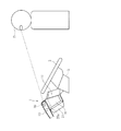
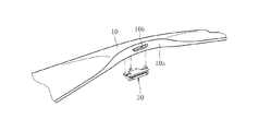
図1には運転席周辺の側面図、図2にはメータ類周辺部の正面図、図3にはインストルメントパッドとカメラユニットとの分解斜視図がそれぞれ示されており、以下これらの図に基づき説明する。 1 is a side view around the driver's seat, FIG. 2 is a front view around the meters, and FIG. 3 is an exploded perspective view of the instrument pad and the camera unit. This will be explained based on this.
本実施形態の運転席は、バスのキャブ内にある運転席である。運転席の前方には、車幅方向に延びたインストルメントパネル1が設けられている。インストルメントパネル1の下部からは、ステアリングカバー2を介してステアリングホイール3が設けられている。
The driver seat of this embodiment is a driver seat in the cab of the bus. An
インストルメントパネル1は、図1に示す範囲においては、上面を形成するインストルメントパッド10及び運転席側の側面を形成するメータベゼル11を有している。
In the range shown in FIG. 1, the
メータベゼル11には、車両前方側(運転席に対して奥側)に延びる略角筒状のフード部20が形成されており、フード部20の前部にはスピードメータ21a及びタコメータ21b等のメータ類を備えたメータクラスタ21が取り付けられている。
The
インストルメントパッド10とフード部20の上壁部20aとの間には空間15が形成されており、当該空間15内に運転者監視用のカメラユニット30(運転者監視カメラ)が配設されている。
A
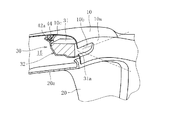
詳しくは、図3に示すように、インストルメントパッド10はメータベゼル11のフード部20に対応する位置が上方に膨出している。そしてこの膨出部分の後側(運転席側)の縁部は下方に延びる後面部10aが形成されている。そして、後面部10aにはカメラユニット30の取付位置に合わせて、開口部10bが形成されている。
In detail, as shown in FIG. 3, the
カメラユニット30は図4に示すように、カメラ本体31とブラケット32とから構成されており、カメラ本体31がブラケット32と係合して保持される。詳しくは、カメラ本体31は一側面にレンズ部31aを有している。ブラケット32は、カメラ本体31の下面とレンズ部31aを除く3つの側面を覆うよう、下面部40と3つの側面部41、42、43を有している。各側面部41、42、43の上端からは取付片41a、42a、43aが延びており、各取付片41a、42a、43aには取付孔41b、42b、43bが形成されている。
As shown in FIG. 4, the
そして、図5に示すようにインストルメントパッド10の内面には、カメラユニット30のブラケット32の各取付片41a、42a、43aに対応した位置にボス部10cが形成されており(図5では1つのみを示す)、当該ボス部10cにも取付孔(図示せず)が形成されている。
As shown in FIG. 5, a
カメラユニット30は、インストルメントパッド10内面の各ボス部10cにブラケット32の各取付片41a、42a、43aが合わせられ、ボルト44が各ボス部10c及び各取付片41a、42a、43aの取付孔41b、42b、43bに貫通して締結されることで取り付けられている。また、図示しないがカメラ本体は車両に搭載されているECU(電子コントロールユニット)等と電気的に接続されている。
In the
このようにして取り付けられているカメラユニット30は、カメラ本体31のレンズ部31aがインストルメントパッド10の開口部10bに臨んでおり、カメラ本体30は開口部10bを通して運転者Dの顔を撮影する。なお、カメラ本体30による撮影は静止画であっても、動画であってもよく、撮影して得た情報はECU等に送られて処理される。
In the
図1に示すように、カメラユニット30は、インストルメントパネル1の上面を形成するインストルメントパッド10の内面に取り付けられていることから、ステアリングホイール3よりも十分高い位置にある。したがって、ステアリングホイール3の位置を調節可能である場合でも、ステアリングホイール3が比較的低い位置に調節されていれば、図1に点線で示すようにカメラ本体30のレンズ部31aと運転者Dとの間をステアリングホイール3が遮ることはない。
As shown in FIG. 1, since the
また、カメラユニット30はインストルメントパッド10とフード部20の上壁部20aとの間の空間15に収納され、インストルメントパッド10の後面部10aに形成された開口部10bを通して運転者を撮影することから、フード部20には突出部等が形成されることはない。従って、運転者がメータ類を視認する際にも視界を遮るものはなく、且つ内装の見栄えを悪化させることもない。
The
以上のように、本実施形態に係る運転者監視カメラ配置構造によれば、運転者のメータ視認や内装の見栄えに影響を与えずに運転者監視カメラを設置することができる。 As described above, according to the driver monitoring camera arrangement structure according to the present embodiment, the driver monitoring camera can be installed without affecting the driver's meter viewing and the appearance of the interior.
以上で本発明に係る運転者監視カメラ配置構造の実施形態についての説明を終えるが、実施形態は上記実施形態に限られるものではない。 Although the description of the embodiment of the driver monitoring camera arrangement structure according to the present invention is finished above, the embodiment is not limited to the above embodiment.
上記実施形態ではバスに本発明の運転者監視カメラ配置構造を適用しているが、本発明を適用可能な車両はバスに限られるものではなく、トラック、乗用車等にも適用可能である。 In the above embodiment, the driver monitoring camera arrangement structure of the present invention is applied to a bus. However, vehicles to which the present invention can be applied are not limited to buses, and can be applied to trucks, passenger cars, and the like.
また上記実施形態では、カメラユニット30がインストルメントパッドのボスを介して取り付けられているが、カメラユニットはインストルメントパッドとフード部との間に形成される空間15に収納されればよく、例えば、フード部側に取り付けられる構成としてもよい。
Moreover, in the said embodiment, although the
1 インストルメントパネル
10 インストルメントパッド
10a 後面部
10b 開口部
11 メータベゼル
20 フード部
20a 上壁部
21 メータクラスタ
30 カメラユニット
31 カメラ本体
31a レンズ部
32 ブラケット
40 下面部
41、42、43 側面部
41a、42a、43a 取付片
41b、42b、43b 取付孔
44 ボルト
DESCRIPTION OF
Claims (3)
前記インストルメントパネルの上面を形成するインストルメントパッドと、
前記インストルメントパネルの運転席側の側面を形成するメータベゼルと、
前記メータベゼルにて、車両前方側に延びる筒形状のフード部と、
前記フード部の前部に設けられるメータ類と、
前記インストルメントパッドと前記フード部との間に形成される空間に収納され、運転者を撮影する運転者監視カメラと、
を備える運転者監視カメラ配置構造。 An instrument panel provided in front of the driver's seat of the vehicle;
An instrument pad forming the upper surface of the instrument panel;
A meter bezel that forms a side surface on the driver's seat side of the instrument panel;
In the meter bezel, a cylindrical hood portion extending forward of the vehicle,
Meters provided at the front of the hood,
A driver monitoring camera that is housed in a space formed between the instrument pad and the hood, and shoots the driver;
A driver surveillance camera arrangement structure comprising:
Priority Applications (1)
| Application Number | Priority Date | Filing Date | Title |
|---|---|---|---|
| JP2015243815A JP2017109537A (en) | 2015-12-15 | 2015-12-15 | Driver monitoring camera arrangement structure |
Applications Claiming Priority (1)
| Application Number | Priority Date | Filing Date | Title |
|---|---|---|---|
| JP2015243815A JP2017109537A (en) | 2015-12-15 | 2015-12-15 | Driver monitoring camera arrangement structure |
Publications (2)
| Publication Number | Publication Date |
|---|---|
| JP2017109537A true JP2017109537A (en) | 2017-06-22 |
| JP2017109537A5 JP2017109537A5 (en) | 2019-01-31 |
Family
ID=59079368
Family Applications (1)
| Application Number | Title | Priority Date | Filing Date |
|---|---|---|---|
| JP2015243815A Pending JP2017109537A (en) | 2015-12-15 | 2015-12-15 | Driver monitoring camera arrangement structure |
Country Status (1)
| Country | Link |
|---|---|
| JP (1) | JP2017109537A (en) |
Citations (3)
| Publication number | Priority date | Publication date | Assignee | Title |
|---|---|---|---|---|
| JP2008189230A (en) * | 2007-02-07 | 2008-08-21 | Hino Motors Ltd | Driver image pickup device |
| JP2013086750A (en) * | 2011-10-21 | 2013-05-13 | Suzuki Motor Corp | Input device for vehicle |
| JP2014172554A (en) * | 2013-03-12 | 2014-09-22 | Calsonic Kansei Corp | Camera-equipped display device |
-
2015
- 2015-12-15 JP JP2015243815A patent/JP2017109537A/en active Pending
Patent Citations (3)
| Publication number | Priority date | Publication date | Assignee | Title |
|---|---|---|---|---|
| JP2008189230A (en) * | 2007-02-07 | 2008-08-21 | Hino Motors Ltd | Driver image pickup device |
| JP2013086750A (en) * | 2011-10-21 | 2013-05-13 | Suzuki Motor Corp | Input device for vehicle |
| JP2014172554A (en) * | 2013-03-12 | 2014-09-22 | Calsonic Kansei Corp | Camera-equipped display device |
Similar Documents
| Publication | Publication Date | Title |
|---|---|---|
| US10252671B2 (en) | Motor vehicle having a rear view device with no wing mirrors | |
| JP5628778B2 (en) | In-vehicle camera mounting device | |
| JP2014208529A (en) | Mirror alternative system for vehicle | |
| JP2013244752A (en) | Vehicular inner mirror system, and vehicle including the same | |
| JP2009023543A (en) | Vehicle and driving support device of vehicle | |
| JP2016037109A (en) | Rear visual recognition device | |
| JP2004082829A (en) | On-vehicle camera | |
| JP2011228957A (en) | Camera unit mounting method and camera unit | |
| JP5851009B2 (en) | In-vehicle camera mounting device | |
| JP5260398B2 (en) | Camera arrangement structure | |
| JP2013216290A (en) | High-mount stop lamp | |
| JP5632967B2 (en) | Vehicle mounted camera | |
| JP2017109537A (en) | Driver monitoring camera arrangement structure | |
| JP2015074316A (en) | Display device for vehicle | |
| JP2017081261A (en) | Cover of stereo camera | |
| JP2018016199A (en) | Bracket attachment structure for vehicle auxiliary machine | |
| JP6760047B2 (en) | Vehicle peripheral monitoring device | |
| JP6557862B2 (en) | Electronic mirror device | |
| JP2017124732A (en) | Attachment structure of back camera for vehicle | |
| JP2011057031A (en) | Vehicle backward image pickup device and back monitoring system using this device | |
| JP6770413B2 (en) | Vehicle interior camera mounting structure | |
| JP2015205618A (en) | Mounting method of on-vehicle side camera and on-vehicle side camera | |
| JP2017061216A (en) | On-board imaging system, vehicle and imaging method | |
| CN110861583A (en) | Vehicle image pickup unit | |
| TWM479253U (en) | Vehicle image safety system |
Legal Events
| Date | Code | Title | Description |
|---|---|---|---|
| A521 | Request for written amendment filed |
Free format text: JAPANESE INTERMEDIATE CODE: A523 Effective date: 20181214 |
|
| A621 | Written request for application examination |
Free format text: JAPANESE INTERMEDIATE CODE: A621 Effective date: 20181214 |
|
| RD02 | Notification of acceptance of power of attorney |
Free format text: JAPANESE INTERMEDIATE CODE: A7422 Effective date: 20181214 |
|
| A977 | Report on retrieval |
Free format text: JAPANESE INTERMEDIATE CODE: A971007 Effective date: 20190911 |
|
| A131 | Notification of reasons for refusal |
Free format text: JAPANESE INTERMEDIATE CODE: A131 Effective date: 20190918 |
|
| A02 | Decision of refusal |
Free format text: JAPANESE INTERMEDIATE CODE: A02 Effective date: 20200527 |