JP2017104821A - Syringe pump - Google Patents

Syringe pump Download PDF

Info

Publication number
JP2017104821A
JP2017104821A JP2015241928A JP2015241928A JP2017104821A JP 2017104821 A JP2017104821 A JP 2017104821A JP 2015241928 A JP2015241928 A JP 2015241928A JP 2015241928 A JP2015241928 A JP 2015241928A JP 2017104821 A JP2017104821 A JP 2017104821A
Authority
JP
Japan
Prior art keywords
syringe
piston
liquid
syringe pump
opening
Prior art date
Legal status (The legal status is an assumption and is not a legal conclusion. Google has not performed a legal analysis and makes no representation as to the accuracy of the status listed.)
Pending
Application number
JP2015241928A
Other languages
Japanese (ja)
Inventor
裕之 村岡
Hiroyuki Muraoka
裕之 村岡
Current Assignee (The listed assignees may be inaccurate. Google has not performed a legal analysis and makes no representation or warranty as to the accuracy of the list.)
Koganei Corp
Original Assignee
Koganei Corp
Priority date (The priority date is an assumption and is not a legal conclusion. Google has not performed a legal analysis and makes no representation as to the accuracy of the date listed.)
Filing date
Publication date
Application filed by Koganei Corp filed Critical Koganei Corp
Priority to JP2015241928A priority Critical patent/JP2017104821A/en
Publication of JP2017104821A publication Critical patent/JP2017104821A/en
Pending legal-status Critical Current

Links

Images

Abstract

PROBLEM TO BE SOLVED: To improve the discharge accuracy of a syringe pump.SOLUTION: A syringe pump 10 discharges a liquid L in a syringe 11, in which a discharge part 13 is provided at one end and an opening 14 is provided at the other end, from the discharge part 13. The syringe pump 10 has: a piston 26 inserted into the syringe 11 from the opening 14; and a seal member 32 which seals a space between the piston 26 and the syringe 11. An exhaust hole 33 which allows communication between the interior and the exterior of the syringe 11 is provided at the piston 26. Air in the syringe 11 is exhausted through the exhaust hole 33 when the liquid L in the syringe 11 and the piston 26 relatively move close to each other. After the air is exhausted, the exhaust hole 33 is closed by an opening/closing member 34.SELECTED DRAWING: Figure 2

Description

本発明は、シリンジ内に充填された液体をシリンジの吐出部から吐出するシリンジポンプに関する。   The present invention relates to a syringe pump that discharges a liquid filled in a syringe from a discharge portion of the syringe.

シリンジポンプは、シリンジ内に充填された薬液やペースト状の接着剤等の液体をシリンジの吐出部から定量吐出するために使用され、液体ディスペンサーとも言われる。予め液体が充填されたシリンジからシリンジポンプにより液体を吐出するときには、シリンジはシリンジポンプのピストンと同軸状に支持台に装着され、シリンジポンプにより液体が吐出される。一方、シリンジが支持台に装着された状態のままで、空のシリンジ内に液体を充填し、充填後に液体を吐出するようにした形態のシリンジポンプがある。この形態においては、シリンジ内への液体の充填は、ピストンがシリンジから取り出された状態のもとで行われる。シリンジ内に液体が充填されると、シリンジ内の空気は液面上昇により外部に排出される。   The syringe pump is used to quantitatively discharge a liquid such as a chemical solution or a paste-like adhesive filled in the syringe from a discharge portion of the syringe, and is also referred to as a liquid dispenser. When liquid is discharged from a syringe filled with liquid in advance by a syringe pump, the syringe is mounted on the support base coaxially with the piston of the syringe pump, and the liquid is discharged by the syringe pump. On the other hand, there is a syringe pump in a form in which an empty syringe is filled with a liquid while the syringe is mounted on a support, and the liquid is discharged after filling. In this form, the filling of the liquid into the syringe is performed under the state where the piston is taken out from the syringe. When the syringe is filled with the liquid, the air in the syringe is discharged to the outside due to the liquid level rising.

特許文献1に記載されるシリンジポンプと、特許文献2に記載される液体ディスペンサーは、予めシリンジに充填された液体をシリンジから吐出する形態である。特許文献1に記載されたシリンジポンプにおいて、シリンジ内に挿入されたピストンはモータ等の機械的手段で駆動され、シリンジ内に充填された薬液を生体に注入するために使用される。   The syringe pump described in Patent Document 1 and the liquid dispenser described in Patent Document 2 are configured to discharge the liquid previously filled in the syringe from the syringe. In the syringe pump described in Patent Document 1, a piston inserted into a syringe is driven by mechanical means such as a motor, and used to inject a medical solution filled in the syringe into a living body.

特許文献2に記載された液体ディスペンサーは、シリンジ内に挿入されるプランジャは圧縮空気により押され、シリンジ内に充填されたペースト状の電子材料や接着剤等の液体材料を圧縮空気によりシリンジから吐出させて被塗布部に塗布するために使用される。圧縮空気によりプランジャを介して液体が加圧されると、圧縮空気の圧力変動、気温変化による液体の粘度変動などにより、吐出流量が変動する。   In the liquid dispenser described in Patent Document 2, the plunger inserted into the syringe is pushed by the compressed air, and the liquid material such as a paste-like electronic material or adhesive filled in the syringe is discharged from the syringe by the compressed air. It is used to apply to the part to be applied. When the liquid is pressurized by the compressed air via the plunger, the discharge flow rate fluctuates due to the pressure fluctuation of the compressed air, the viscosity fluctuation of the liquid due to the temperature change and the like.

特開平06−296690号公報Japanese Patent Laid-Open No. 06-296690 特開2000−317370号公報JP 2000-317370 A

予め液体が充填されたシリンジからシリンジポンプにより液体を吐出するために、ピストンがシリンジ内に挿入されると、ピストンと液体との間に空気が残ってしまう。この残留空気は、ピストンにより液体の吐出動作を行うときに、ピストン駆動直後の圧縮と、その後の緩慢な膨張とを繰り返す。従って、液体が定量吐出されるようにピストンが正確に一定長さだけ挿入移動されても、シリンジからの液体の吐出量は変動し、吐出精度を向上させることができない。ピストンをシリンジに挿入したときに、ピストンと液体との間に空気が残っているか否かを外部から観察することができるように、シリンジを透明性の素材で構成することがある。液体とピストンとの間に空気が残っている場合には、ピストンの挿入操作をやり直す必要があり、非常に煩雑である。   When the piston is inserted into the syringe in order to discharge the liquid from the syringe filled with the liquid with a syringe pump, air remains between the piston and the liquid. This residual air repeats compression immediately after driving the piston and slow expansion thereafter when performing a liquid discharge operation by the piston. Therefore, even if the piston is inserted and moved accurately by a certain length so that the liquid is quantitatively discharged, the discharge amount of the liquid from the syringe fluctuates and the discharge accuracy cannot be improved. When the piston is inserted into the syringe, the syringe may be made of a transparent material so that it can be observed from the outside whether air remains between the piston and the liquid. When air remains between the liquid and the piston, it is necessary to redo the piston insertion operation, which is very complicated.

一方、支持台にシリンジが装着された状態のままで、空のシリンジ内への液体の充填操作と、充填後の液体の吐出動作とを連続的に行うようにした形態のシリンジポンプにおいても、吐出動作時にシリンジにピストンを挿入する。この場合、液体が充填されたシリンジ上部の開口部にはピストンと液体との間に空気が残ってしまうことがある。残留空気があるために、ピストンの移動量と液体の吐出量が一致せず、ピストンの移動量が正確であっても吐出精度を向上させることができない。さらに、液体の充填操作が行われてから、液体の吐出操作に迅速に切り換えることができず、吐出操作性を向上させることができない。   On the other hand, in the syringe pump of the form in which the filling operation of the liquid into the empty syringe and the discharging operation of the liquid after filling are continuously performed with the syringe mounted on the support base, The piston is inserted into the syringe during the discharge operation. In this case, air may remain between the piston and the liquid in the opening at the top of the syringe filled with the liquid. Since there is residual air, the movement amount of the piston does not match the discharge amount of the liquid, and even if the movement amount of the piston is accurate, the discharge accuracy cannot be improved. Further, after the liquid filling operation is performed, it is not possible to quickly switch to the liquid discharging operation, and the discharge operability cannot be improved.

本発明の目的は、シリンジポンプの吐出精度を向上することにある。   An object of the present invention is to improve the discharge accuracy of a syringe pump.

本発明のシリンジポンプは、一端に吐出部が設けられ他端に開口部が設けられたシリンジ内の液体を前記吐出部から吐出するシリンジポンプであって、前記シリンジ内に前記開口部から挿入されるピストンと、前記ピストンと前記シリンジとの間をシールするシール部材と、前記ピストンに設けられ、前記シリンジの内部と外部とを連通する排気孔と、前記排気孔を前記ピストンの内方端面側で開閉する開閉部材と、を有する。   The syringe pump according to the present invention is a syringe pump that discharges liquid in a syringe having a discharge portion at one end and an opening at the other end from the discharge portion, and is inserted into the syringe from the opening portion. A piston that seals between the piston and the syringe, an exhaust hole that is provided in the piston and communicates with the inside and the outside of the syringe, and the exhaust hole is connected to the inner end face side of the piston. And an opening and closing member that opens and closes.

シリンジポンプは、シリンジ内に挿入されるピストンを有し、シリンジの内部と外部とを連通する排気孔がピストンに設けられ、排気孔は開閉部材により開閉されるので、ピストンとシリンジ内の液体とが相対的に接近すると、液面とピストンとの間の空気は、外部に排出される。したがって、ピストンをシリンジ内に移動させて、シリンジの吐出部から液体を吐出する際には、ピストンは液体を直接駆動することができる。これにより、吐出部からの液体の吐出流量は、ピストンの前進ストロークに対応する体積の変化量と完全に一致し、シリンジポンプの吐出精度を向上させることができる。   The syringe pump has a piston that is inserted into the syringe, an exhaust hole that communicates the inside and outside of the syringe is provided in the piston, and the exhaust hole is opened and closed by an opening and closing member. When they are relatively close, the air between the liquid surface and the piston is discharged to the outside. Therefore, when the piston is moved into the syringe and the liquid is discharged from the discharge portion of the syringe, the piston can directly drive the liquid. Thereby, the discharge flow rate of the liquid from the discharge part completely coincides with the amount of change in volume corresponding to the forward stroke of the piston, and the discharge accuracy of the syringe pump can be improved.

(A)は空のシリンジ内に液体容器内の液体を充填している状態におけるシリンジポンプを示す断面図であり、(B)はシリンジ内に液体が充填された状態におけるシリンジポンプを示す断面図である。(A) is sectional drawing which shows the syringe pump in the state which has filled the liquid in the liquid container in the empty syringe, (B) is sectional drawing which shows the syringe pump in the state with which the liquid was filled in the syringe. It is. シリンジ内に充填された液体を吐出している状態におけるシリンジポンプを示す断面図である。It is sectional drawing which shows the syringe pump in the state which is discharging the liquid with which it filled in the syringe. 予め液体が充填されたシリンジが配置された状態のシリンジポンプを示す断面図である。It is sectional drawing which shows the syringe pump of the state by which the syringe with which the liquid was filled beforehand is arrange | positioned. (A)はピストンがシリンジの開口端部に装着された状態におけるシリンジポンプを示す断面図であり、(B)はピストンと液体との間の残留空気が外部に排出された状態におけるシリンジポンプを示す断面図である。(A) is sectional drawing which shows the syringe pump in the state with which the piston was mounted | worn with the opening edge part of a syringe, (B) is a syringe pump in the state in which the residual air between a piston and a liquid was discharged | emitted outside. It is sectional drawing shown. シリンジポンプのピストンの一例を示す断面図である。It is sectional drawing which shows an example of the piston of a syringe pump. シリンジポンプのピストンの他の一例を示す断面図である。It is sectional drawing which shows another example of the piston of a syringe pump. シリンジポンプの他の実施の形態を示す断面図である。It is sectional drawing which shows other embodiment of a syringe pump.

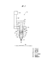
以下、本発明の実施の形態を図面に基づいて詳細に説明する。図1および図2に示されるシリンジポンプ10は、シリンジ11の中に液体Lを充填し、充填操作に引き続いてシリンジ11内の液体Lを吐出する。シリンジ11は、円筒形状の本体部12と、本体部12の一端部に設けられた吐出部13と、他端部に設けられた開口部14とを有し、フランジ15が径方向外方に突出して開口部14に設けられている。   Hereinafter, embodiments of the present invention will be described in detail with reference to the drawings. The syringe pump 10 shown in FIGS. 1 and 2 fills the syringe 11 with the liquid L, and discharges the liquid L in the syringe 11 following the filling operation. The syringe 11 has a cylindrical main body portion 12, a discharge portion 13 provided at one end portion of the main body portion 12, and an opening portion 14 provided at the other end portion, and the flange 15 is radially outward. It protrudes and is provided in the opening 14.

シリンジ11内に充填される液体Lは、上端に開口部を有する液体容器16に収容され、液体容器16は加圧容器17内に配置される。加圧容器17は開閉自在の蓋部材17aを有し、液体容器16を加圧容器17内に配置したり、加圧容器17内から取り出したりするときには、蓋部材17aは開閉される。必要に応じて、圧縮空気が加圧容器17に圧縮空気供給源18から供給される。液体供給管19が液体容器16内に挿入され、液体供給管19は吐出部13に接続される。蓋部材17aが閉じられた状態のもとで、加圧容器17に圧縮空気を供給すると、液体容器16に圧縮空気が流入し、液体容器16の液面は加圧される。これにより、液体容器16内の液体Lの液面が加圧上昇されて、液体Lがシリンジ11内に充填される。図1(A)は、空のシリンジ11内に液体容器16内の液体を充填している状態を示す。   The liquid L filled in the syringe 11 is accommodated in a liquid container 16 having an opening at the upper end, and the liquid container 16 is disposed in a pressurized container 17. The pressurization container 17 has an openable / closable lid member 17a. When the liquid container 16 is disposed in the pressurization container 17 or taken out from the pressurization container 17, the lid member 17a is opened and closed. Compressed air is supplied to the pressurized container 17 from the compressed air supply source 18 as necessary. A liquid supply pipe 19 is inserted into the liquid container 16, and the liquid supply pipe 19 is connected to the discharge unit 13. When compressed air is supplied to the pressurized container 17 with the lid member 17a being closed, the compressed air flows into the liquid container 16 and the liquid level of the liquid container 16 is pressurized. Thereby, the liquid level of the liquid L in the liquid container 16 is pressurized and raised, and the liquid L is filled in the syringe 11. FIG. 1A shows a state in which the empty syringe 11 is filled with the liquid in the liquid container 16.

シリンジポンプ10は、支持台21に設けられたコラム22を有し、駆動アーム23がコラム22に上下方向に往復動自在に装着されている。モータ24がコラム22に装着され、モータ24により回転駆動される図示しない送りねじがコラム22の内部に設けられ、駆動アーム23は送りねじにねじ結合される。駆動ロッド25の基端部が駆動アーム23に取り付けられ、駆動ロッド25の先端部にピストン26が取り付けられる。ピストン26は、図1および図2に示されるように、シリンジ11内に開口部14側から挿入される。   The syringe pump 10 has a column 22 provided on a support base 21, and a drive arm 23 is mounted on the column 22 so as to be able to reciprocate up and down. A motor 24 is mounted on the column 22, a feed screw (not shown) that is rotationally driven by the motor 24 is provided inside the column 22, and the drive arm 23 is screwed to the feed screw. A proximal end portion of the drive rod 25 is attached to the drive arm 23, and a piston 26 is attached to the distal end portion of the drive rod 25. As shown in FIGS. 1 and 2, the piston 26 is inserted into the syringe 11 from the opening 14 side.

ピストン26がシリンジ11内に挿入されるときには、シリンジ11は開口部14を上端とし、吐出部13を下側として駆動ロッド25と同軸状に支持台21に配置される。環状溝31がピストン26の先端部に設けられ、この環状溝31にシール部材32が装着される。これにより、ピストン26がシリンジ11内に挿入されると、ピストン26の外周面とシリンジ11の内周面との間はシールされる。なお、ピストン26が長い場合には、シリンジ11の内面に環状溝を設け、シール部材32をシリンジ11側の環状溝に設けるようにしても良い。排気孔33がピストン26に設けられており、シールされた密閉空間であるシリンジ11の内部と大気つまり外部とは、排気孔33を介して相互に連通する。   When the piston 26 is inserted into the syringe 11, the syringe 11 is arranged on the support base 21 coaxially with the drive rod 25 with the opening portion 14 as the upper end and the discharge portion 13 as the lower side. An annular groove 31 is provided at the tip of the piston 26, and a seal member 32 is attached to the annular groove 31. Thereby, when the piston 26 is inserted into the syringe 11, the space between the outer peripheral surface of the piston 26 and the inner peripheral surface of the syringe 11 is sealed. When the piston 26 is long, an annular groove may be provided on the inner surface of the syringe 11 and the seal member 32 may be provided in the annular groove on the syringe 11 side. An exhaust hole 33 is provided in the piston 26, and the inside of the syringe 11, which is a sealed sealed space, and the atmosphere, that is, the outside, communicate with each other via the exhaust hole 33.

開閉部材34がピストン26の先端に設けられ、シリンジ11内の液体の液面とピストン26とが相互に接近するときには、開閉部材34は排気孔33を開放する。これにより、液体Lとピストン26との間の空気は排気孔33を介して外部に排出される。空気が排出されると、液体Lはピストン26の先端面つまり内方端面35に接触する。空気が排出された後には、開閉部材34により排気孔33が閉じられる。開閉部材34は、ピストン26の先端面つまり内方端面35に接触するシール面36を備えており、シール面36が内方端面35に接触すると、液体Lは排気孔33内へ流入しない。   When the opening / closing member 34 is provided at the tip of the piston 26 and the liquid level of the liquid in the syringe 11 and the piston 26 approach each other, the opening / closing member 34 opens the exhaust hole 33. Thereby, the air between the liquid L and the piston 26 is discharged to the outside through the exhaust hole 33. When the air is discharged, the liquid L comes into contact with the front end surface of the piston 26, that is, the inner end surface 35. After the air is discharged, the exhaust hole 33 is closed by the opening / closing member 34. The opening / closing member 34 includes a seal surface 36 that contacts the front end surface of the piston 26, that is, the inner end surface 35. When the seal surface 36 contacts the inner end surface 35, the liquid L does not flow into the exhaust hole 33.

排気孔33は、ピストン26の内方端面35に開口しピストン26の径方向中心部に軸方向に伸びる軸方向孔33aと、この軸方向孔33aに対して直角方向に伸びる径方向孔33bとを有する。径方向孔33bは、シール部材32よりもピストン26の後端部側つまり図1および図2において上端部側に開口しており、シリンジ11の外部と軸方向孔33aは径方向孔33bを介して相互に連通する。   The exhaust hole 33 opens to the inner end surface 35 of the piston 26 and extends in the axial direction at the radial center of the piston 26, and the radial hole 33b extends in a direction perpendicular to the axial hole 33a. Have The radial hole 33b is opened to the rear end side of the piston 26 from the seal member 32, that is, the upper end side in FIGS. 1 and 2, and the outside of the syringe 11 and the axial hole 33a are interposed via the radial hole 33b. Communicate with each other.

空のシリンジ11内に液体容器16内の液体Lを充填するには、図1(A)に示されるように、シリンジ11が支持台21に配置され、シリンジ11の吐出部13に液体供給管19が接続される。さらに、ピストン26がシリンジ11の上端部つまり開口部14内に装着される。このときには、ピストン26は、シール部材32がシリンジ11の内周面に接触する位置となるまでシリンジ11内に挿入された位置で停止される。この状態のもとで、圧縮空気供給源18から加圧容器17内に圧縮空気を供給すると、液体容器16内の液面には圧縮空気の圧力が加えられる。これにより、液体容器16内の液体Lは、液体供給管19によりシリンジ11内に充填され、液体Lの液面がピストン26に向けて接近する。   In order to fill the empty syringe 11 with the liquid L in the liquid container 16, as shown in FIG. 1A, the syringe 11 is disposed on the support base 21, and the liquid supply pipe is connected to the discharge portion 13 of the syringe 11. 19 is connected. Further, the piston 26 is mounted in the upper end portion of the syringe 11, that is, the opening portion 14. At this time, the piston 26 is stopped at a position where it is inserted into the syringe 11 until the seal member 32 comes into contact with the inner peripheral surface of the syringe 11. Under this state, when compressed air is supplied into the pressurized container 17 from the compressed air supply source 18, the pressure of the compressed air is applied to the liquid surface in the liquid container 16. Thereby, the liquid L in the liquid container 16 is filled into the syringe 11 by the liquid supply pipe 19, and the liquid surface of the liquid L approaches toward the piston 26.

図1(A)は、液体容器16内の液体がシリンジ11内に充填される状態を示しており、液体充填操作時には開閉部材34は排気孔33を開放する。これにより、液面とピストン26との間の空気は、液面上昇に伴って排気孔33を介してシリンジ11の外部に排出される。液体の充填操作がさらに進んで、図1(B)に示されるように、液体Lがピストン26の内方端面35に接触すると、シリンジ11内の空気は完全に外部に排出され、液体Lの充填が完了する。このときに、開閉部材34が上端まで上昇し、開閉部材34のシール面36はピストン26の内方端面35に接触し、排気孔33が閉じられ、液体Lのみがシリンジ11の内部に封入された状態となる。このように、シリンジ11内の空気の排出が完了すると、開閉部材は排気孔を閉じる。   FIG. 1A shows a state in which the liquid in the liquid container 16 is filled into the syringe 11, and the opening / closing member 34 opens the exhaust hole 33 during the liquid filling operation. Thereby, the air between the liquid level and the piston 26 is discharged to the outside of the syringe 11 through the exhaust hole 33 as the liquid level rises. When the liquid filling operation further proceeds and the liquid L comes into contact with the inner end surface 35 of the piston 26 as shown in FIG. 1B, the air in the syringe 11 is completely discharged to the outside, and the liquid L Filling is complete. At this time, the opening / closing member 34 rises to the upper end, the sealing surface 36 of the opening / closing member 34 contacts the inner end surface 35 of the piston 26, the exhaust hole 33 is closed, and only the liquid L is sealed inside the syringe 11. It becomes a state. Thus, when the discharge of air in the syringe 11 is completed, the opening / closing member closes the exhaust hole.

開閉部材34は、内方端面35に接触する円形のシール面36と、シリンジ11の吐出部13に向けて突出する先端側の頂部とを有し、開閉部材34の断面は円錐形状となっている。円錐形状の開閉部材34は先端から外周に向けて傾斜した傾斜面37を有しており、液面が開閉部材34の先端に接触してから更に上昇すると、液体Lは先端の頂部から外周に向けて案内される。これにより、液面がピストン26に接近すると、開閉部材34と液面との間の空気は、開閉部材34の外周に案内されて、シリンジ11の内部に残留することなく、確実に外部に排出される。開閉部材34の断面形状としては、円錐形状に限られることなく、先端部が突出した断面半円形としても良い。   The opening / closing member 34 has a circular seal surface 36 that contacts the inner end surface 35 and a top portion on the tip side that protrudes toward the discharge portion 13 of the syringe 11, and the opening / closing member 34 has a conical cross section. Yes. The conical opening / closing member 34 has an inclined surface 37 inclined from the tip toward the outer periphery, and when the liquid level further rises after contacting the tip of the opening / closing member 34, the liquid L moves from the top of the tip to the outer periphery. Guided towards. As a result, when the liquid level approaches the piston 26, the air between the opening / closing member 34 and the liquid level is guided to the outer periphery of the opening / closing member 34, and is reliably discharged outside without remaining inside the syringe 11. Is done. The cross-sectional shape of the opening / closing member 34 is not limited to a conical shape, and may be a semicircular cross-section with a protruding tip.

開閉部材34は、ピストン26の内方端面35で排気口33を開閉する。つまり、液面に一番近い場所で、開閉部材34は排気口33を開閉する。液面から離れた場所で排気口33を開閉すると、液面から開閉箇所までの距離がデッドボリュームとなって空気が残留することになる。本発明では、開閉部材34は、液面に一番近い場所で排気口33を開閉するので、そのようなデッドボリュームが生じることはなく、空気がシリンジ11の内部に残留することはない。   The opening / closing member 34 opens and closes the exhaust port 33 at the inner end surface 35 of the piston 26. That is, the opening / closing member 34 opens and closes the exhaust port 33 at a location closest to the liquid level. When the exhaust port 33 is opened and closed at a location away from the liquid level, the distance from the liquid level to the open / close location becomes a dead volume, and air remains. In the present invention, since the opening / closing member 34 opens and closes the exhaust port 33 at a location closest to the liquid level, such dead volume does not occur and air does not remain inside the syringe 11.

シリンジ11内への液体の充填が完了すると、加圧容器17はシリンジ11の下方から撤去され、図2に示されるように、シリンジ11の下方には被塗布部材Wが配置される。図2は被塗布部材Wに対して液体Lを吐出している状態を示す。このように、被塗布部材Wが配置される吐出作業ステージに、シリンジポンプ10を設けると、液体が空となったり、残量が低下したシリンジ11内に、液体容器16の液体Lを充填し、充填後に直ちに被塗布部材Wに対して液体塗布操作を行うことができる。これにより、被塗布部材Wに対する液体の吐出操作性を向上させることができる。   When the filling of the liquid into the syringe 11 is completed, the pressurized container 17 is removed from the lower side of the syringe 11, and as shown in FIG. FIG. 2 shows a state in which the liquid L is being discharged to the member W to be coated. As described above, when the syringe pump 10 is provided on the discharge operation stage on which the member to be coated W is arranged, the liquid L in the liquid container 16 is filled into the syringe 11 in which the liquid is empty or the remaining amount is reduced. The liquid application operation can be performed on the coated member W immediately after filling. Thereby, the discharge operability of the liquid with respect to the to-be-coated member W can be improved.

さらに、液体塗布時には、ピストン26と液面との間には、空気が残留していないので、駆動ロッド25を下降移動させてピストン26を下方に向けて前進移動させると、吐出部13から吐出される液体の吐出流量は、ピストン26の前進ストロークに対応する体積の変化量と完全に一致する。これにより、吐出部13から吐出されるシリンジポンプ10の吐出精度を向上させることができる。   Furthermore, since air does not remain between the piston 26 and the liquid surface at the time of liquid application, if the drive rod 25 is moved downward and the piston 26 is moved forward downward, the air is discharged from the discharge unit 13. The flow rate of the liquid to be discharged completely coincides with the amount of change in volume corresponding to the forward stroke of the piston 26. Thereby, the discharge precision of the syringe pump 10 discharged from the discharge part 13 can be improved.

駆動ロッド25は、上述のように、モータ24により駆動される形態であるが、駆動ロッド25を往復動するための駆動手段としては、モータ24に限られず、空気圧シリンダや油圧シリンダを使用しても良い。   The drive rod 25 is driven by the motor 24 as described above. However, the drive means for reciprocating the drive rod 25 is not limited to the motor 24, and a pneumatic cylinder or a hydraulic cylinder is used. Also good.

図1および図2は、被塗布部材Wに液体を塗布する塗布作業ステージにおいて、シリンジ11内への液体の充填操作と、塗布操作とを行う場合を示す。シリンジ11には、液体充填と液体吐出とを繰り返して行うタイプと、予め液体が充填されたシリンジ11を塗布作業ステージに配置して、液体の吐出作業のみを行うタイプがある。   1 and 2 show a case where an operation of filling a liquid into the syringe 11 and an application operation are performed in an application operation stage for applying a liquid to the member W to be applied. The syringe 11 includes a type in which liquid filling and liquid discharge are repeatedly performed, and a type in which the syringe 11 preliminarily filled with liquid is disposed on an application work stage and only liquid discharge work is performed.

図3および図4は、予め液体が充填されたシリンジ11を用いて液体の塗布作業を行う場合のシリンジポンプ10を示す。シリンジポンプ10の構造は、上述した場合と同様である。   3 and 4 show the syringe pump 10 when the liquid application operation is performed by using the syringe 11 filled with the liquid in advance. The structure of the syringe pump 10 is the same as that described above.

図3に示されるように、予め液体Lが充填されたシリンジ11は支持台21に配置される。液体Lはシリンジ11の上端面の位置までは充填されておらず、シリンジ11の開口部14には空気が入り込んでいる。予め液体が充填されたシリンジ11の吐出部13と開口部14は、シール部材によりシールされており、シリンジ11はシール部材が取り除かれてピストン26の下方に配置される。この状態のもとで、図4(A)に示されるように、駆動ロッド25がモータ24により下方に駆動され、ピストン26はシリンジ11の開口部14内に挿入される。   As shown in FIG. 3, the syringe 11 preliminarily filled with the liquid L is disposed on the support base 21. The liquid L is not filled up to the position of the upper end surface of the syringe 11, and air enters the opening 14 of the syringe 11. The discharge part 13 and the opening part 14 of the syringe 11 filled with the liquid in advance are sealed by a seal member, and the syringe 11 is disposed below the piston 26 with the seal member removed. Under this state, as shown in FIG. 4A, the drive rod 25 is driven downward by the motor 24, and the piston 26 is inserted into the opening 14 of the syringe 11.

図4(A)は、ピストン26のシール部材32がシリンジ11の内周面に接触する位置となるまでピストン26がシリンジ11内に挿入される状態を示す。このときには、液体Lの液面とピストン26の間には空気が残留しており、開閉部材34は排気孔33を開放している。ピストン26をシリンジ11の吐出部13に向けて前進移動させると、ピストン26は液体に接近する。ピストン26の接近移動により、残留空気は、排気孔33を通って外部に排出される。   FIG. 4A shows a state where the piston 26 is inserted into the syringe 11 until the seal member 32 of the piston 26 comes into contact with the inner peripheral surface of the syringe 11. At this time, air remains between the liquid level of the liquid L and the piston 26, and the opening / closing member 34 opens the exhaust hole 33. When the piston 26 is moved forward toward the discharge part 13 of the syringe 11, the piston 26 approaches the liquid. Residual air is discharged to the outside through the exhaust hole 33 due to the approaching movement of the piston 26.

ピストン26を液体に接近させて、残留空気が全て外部に排出されると、図4(B)に示されるように、液体Lがピストン26の内方端面35に接触する。これにより、シリンジポンプ10は液体の吐出操作を開始できる状態となる。このときに、開閉部材34により排気孔33が閉じられると、開閉部材34のシール面36はピストン26の内方端面に接触し、液体Lのみがシリンジ11の内部に封入された状態となる。つまり、液体の吐出操作を開始できる状態となる。   When the piston 26 is brought close to the liquid and all the residual air is discharged to the outside, the liquid L contacts the inner end face 35 of the piston 26 as shown in FIG. Thereby, the syringe pump 10 is in a state where the liquid discharge operation can be started. At this time, when the exhaust hole 33 is closed by the opening / closing member 34, the seal surface 36 of the opening / closing member 34 comes into contact with the inner end surface of the piston 26, and only the liquid L is sealed inside the syringe 11. That is, the liquid discharge operation can be started.

吐出操作が開始可能となると、図2に示した場合と同様に、シリンジ11の下方には被塗布部材Wが配置され、被塗布部材Wに対して液体Lが吐出される。液体吐出時には、ピストン26と液面との間には、空気が残留していないので、駆動ロッド25を下降移動させてピストン26を下方に向けて前進移動させると、吐出部13から吐出される液体の吐出流量は、ピストン26の前進ストロークに対応する体積の変化量と完全に一致する。これにより、吐出部13から吐出されるシリンジポンプ10の吐出精度を向上させることができる。   When the discharge operation can be started, the coated member W is disposed below the syringe 11 and the liquid L is discharged to the coated member W, as in the case shown in FIG. At the time of liquid discharge, since air does not remain between the piston 26 and the liquid surface, when the drive rod 25 is moved downward and the piston 26 is moved forward downward, the air is discharged from the discharge unit 13. The liquid discharge flow rate completely matches the amount of change in volume corresponding to the forward stroke of the piston 26. Thereby, the discharge precision of the syringe pump 10 discharged from the discharge part 13 can be improved.

シリンジ11内の液体が全て吐出されたら、液体が充填された新たなシリンジ11が支持台21に装填され、上述のように、液体吐出操作が繰り返して行われる。   When all the liquid in the syringe 11 is discharged, a new syringe 11 filled with the liquid is loaded on the support base 21, and the liquid discharge operation is repeated as described above.

図5は、シリンジポンプ10のピストン26の一例を示す断面図である。ピストン26は、先端部26aと、これと一体となった基端部26bとを有する。往復動軸40が先端部26aの軸方向孔33aを貫通してピストン26に装着されている。往復動軸40は軸方向孔33aよりも小径となっており、往復動軸40と軸方向孔33aとの間には空気が流れる隙間が形成される。駆動機構41がピストン26に設けられ、駆動機構41は往復動軸40を軸方向に駆動し、往復動軸40の先端に設けられる開閉部材34は排気孔33を開閉する。   FIG. 5 is a cross-sectional view showing an example of the piston 26 of the syringe pump 10. The piston 26 has a tip end portion 26a and a base end portion 26b integrated therewith. The reciprocating shaft 40 is attached to the piston 26 through the axial hole 33a of the tip end portion 26a. The reciprocating shaft 40 has a smaller diameter than the axial hole 33a, and a gap through which air flows is formed between the reciprocating shaft 40 and the axial hole 33a. A drive mechanism 41 is provided on the piston 26, the drive mechanism 41 drives the reciprocating shaft 40 in the axial direction, and an opening / closing member 34 provided at the tip of the reciprocating shaft 40 opens and closes the exhaust hole 33.

ピストン26の基端部26bは駆動機構41を構成する円筒部42であり、案内孔43が円筒部42の内周面に形成されている。案内孔43は軸方向孔33aと連通しており、空気圧ピストン44が案内孔43に案内されて軸方向に往復動自在に装着される。案内孔43は空気圧ピストン44によりばね室45と空気圧室46とに仕切られている。開閉部材34のシール面36に対して、ピストン26の内方端面35に向かうばね力を付勢するために、圧縮コイルばね47がばね部材として、ばね室45に装着されている。圧縮コイルばね47は、空気圧ピストン44を空気圧室46に向けて押し上げる。空気圧ピストン44と開閉部材34は連結され、または一体に形成されているので、開閉部材34はばね部材のばね力によってピストン26の内方端面35に向かって押し付けられる。   The base end portion 26 b of the piston 26 is a cylindrical portion 42 that constitutes the drive mechanism 41, and a guide hole 43 is formed on the inner peripheral surface of the cylindrical portion 42. The guide hole 43 communicates with the axial hole 33a, and the pneumatic piston 44 is guided by the guide hole 43 and is mounted so as to be capable of reciprocating in the axial direction. The guide hole 43 is partitioned into a spring chamber 45 and a pneumatic chamber 46 by a pneumatic piston 44. In order to bias the spring force toward the inner end surface 35 of the piston 26 against the seal surface 36 of the opening / closing member 34, a compression coil spring 47 is mounted in the spring chamber 45 as a spring member. The compression coil spring 47 pushes up the pneumatic piston 44 toward the pneumatic chamber 46. Since the pneumatic piston 44 and the opening / closing member 34 are connected or integrally formed, the opening / closing member 34 is pressed toward the inner end surface 35 of the piston 26 by the spring force of the spring member.

ポートプラグ48が円筒部42に取り付けられ、ポートプラグ48は駆動ロッド25の先端に取り付けられる。空気圧室46に連通する給排流路49が、駆動ロッド25とポートプラグ48に設けられ、空気圧室46には外部から圧縮空気が供給される。空気圧室46に圧縮空気を供給すると、空気圧ピストン44はばね力に抗してストッパ51に当接し、開閉部材34は内方端面35から離れる。これにより、図5に示されるように、排気孔33は開放される。空気圧ピストン44がストッパ51に向けて駆動されるときには、ばね室45内の空気は、息付き孔52と、円筒部42の外周面とシリンジ11の内周面との間の隙間を介して外部に排出される。   A port plug 48 is attached to the cylindrical portion 42, and the port plug 48 is attached to the tip of the drive rod 25. A supply / discharge channel 49 communicating with the pneumatic chamber 46 is provided in the drive rod 25 and the port plug 48, and compressed air is supplied to the pneumatic chamber 46 from the outside. When compressed air is supplied to the pneumatic chamber 46, the pneumatic piston 44 abuts against the stopper 51 against the spring force, and the opening / closing member 34 moves away from the inner end surface 35. Thereby, as shown in FIG. 5, the exhaust hole 33 is opened. When the pneumatic piston 44 is driven toward the stopper 51, the air in the spring chamber 45 is externally passed through a breathing hole 52 and a gap between the outer peripheral surface of the cylindrical portion 42 and the inner peripheral surface of the syringe 11. To be discharged.

空気圧室46内の圧縮空気が排出されると、開閉部材34は圧縮コイルばね47のばね力によりピストン26の内方端面35に接触し、排気孔33は閉じられる。ピストン26の内方端面35とシール面36との間をシールするために、シール部材53がシール面36に設けられている。シール部材53は、開閉部材34のシール面36の環状溝に設けられる。環状の溝は、往復動軸40を取り囲むように設けられている。このように、図5に示されるピストン26においては、空気圧シリンダにより構成される駆動機構41を備えている。   When the compressed air in the pneumatic chamber 46 is discharged, the opening / closing member 34 contacts the inner end surface 35 of the piston 26 by the spring force of the compression coil spring 47, and the exhaust hole 33 is closed. A seal member 53 is provided on the seal surface 36 in order to seal between the inner end surface 35 of the piston 26 and the seal surface 36. The seal member 53 is provided in the annular groove of the seal surface 36 of the opening / closing member 34. The annular groove is provided so as to surround the reciprocating shaft 40. As described above, the piston 26 shown in FIG. 5 includes the drive mechanism 41 configured by a pneumatic cylinder.

図5に示されるように、往復動軸40を駆動するため駆動機構41としての円筒部42は、開閉部材34により排気孔33を開放するときに、空気圧室46に圧縮空気を供給する形態であるが、圧縮空気により排気孔33を閉じるように駆動する形態としても良い。さらに、排気孔33を閉じるときと、開放するときのいずれも圧縮空気により空気圧ピストン44を駆動するようにしても良い。   As shown in FIG. 5, the cylindrical portion 42 as the drive mechanism 41 for driving the reciprocating shaft 40 is configured to supply compressed air to the pneumatic chamber 46 when the exhaust hole 33 is opened by the opening / closing member 34. However, it may be configured to be driven so as to close the exhaust hole 33 with compressed air. Furthermore, the pneumatic piston 44 may be driven by compressed air both when the exhaust hole 33 is closed and when it is opened.

図6はシリンジポンプ10のピストン26の他の一例を示す断面図である。このピストン26においては往復動軸40を駆動するための駆動機構41は電磁石つまりソレノイドにより形成される。   FIG. 6 is a cross-sectional view showing another example of the piston 26 of the syringe pump 10. In the piston 26, a drive mechanism 41 for driving the reciprocating shaft 40 is formed by an electromagnet, that is, a solenoid.

図6に示されるように、ソレノイドケース55がピストン26に取り付けられており、ソレノイドケース55に組み込まれるヨーク56内には、コイル57が巻き付けられたボビン58が設けられている。固定鉄心59がボビン58の基端部に取り付けられ、ボビン58の先端部に可動鉄心61が軸方向に往復動自在に装着される。可動鉄心61は往復動軸40に一体に設けられている。ヨーク56の先端部に設けられたカバー62と往復動軸40に設けられたフランジ部63との間には、圧縮コイルばね64がばね部材として装着される。この圧縮コイルばね64は、開閉部材34のシール面36をピストン26の内方端面35から離す方向のばね力を付勢する。したがって、コイル57に電力が印加されないときには、排気孔33は開放される。   As shown in FIG. 6, a solenoid case 55 is attached to the piston 26, and a bobbin 58 around which a coil 57 is wound is provided in a yoke 56 incorporated in the solenoid case 55. The fixed iron core 59 is attached to the base end portion of the bobbin 58, and the movable iron core 61 is attached to the tip end portion of the bobbin 58 so as to be reciprocable in the axial direction. The movable iron core 61 is provided integrally with the reciprocating shaft 40. A compression coil spring 64 is mounted as a spring member between a cover 62 provided at the tip of the yoke 56 and a flange 63 provided on the reciprocating shaft 40. The compression coil spring 64 biases a spring force in a direction in which the seal surface 36 of the opening / closing member 34 is separated from the inner end surface 35 of the piston 26. Therefore, when power is not applied to the coil 57, the exhaust hole 33 is opened.

一方、コイル57に電力を印加すると、ばね力に抗して可動鉄心61が固定鉄心59に向けて駆動され、開閉部材34はピストン26の内方端面35に接触し、排気孔33は閉じられる。   On the other hand, when electric power is applied to the coil 57, the movable iron core 61 is driven toward the fixed iron core 59 against the spring force, the opening / closing member 34 contacts the inner end surface 35 of the piston 26, and the exhaust hole 33 is closed. .

ソレノイドケース55は、ねじ部材65により駆動ロッド25の先端部に取り付けられている。基板収容孔66が駆動ロッド25の先端面とソレノイドケース55の後端面との間に設けられており、制御基板67が基板収容孔66に設けられている。制御基板67には外部から電力が供給され、コイル57の端子は制御基板67に接続される。このように、図6に示されるピストン26においては、電磁石により構成される駆動機構41を備えている。   The solenoid case 55 is attached to the tip of the drive rod 25 by a screw member 65. A substrate accommodation hole 66 is provided between the front end surface of the drive rod 25 and the rear end surface of the solenoid case 55, and a control substrate 67 is provided in the substrate accommodation hole 66. Electric power is supplied to the control board 67 from the outside, and the terminal of the coil 57 is connected to the control board 67. As described above, the piston 26 shown in FIG. 6 includes the drive mechanism 41 constituted by an electromagnet.

図6に示されるように、往復動軸40を駆動するため駆動機構41としての電磁石は、開閉部材34により排気孔33を開放するときには、コイル57に電力を印加することなく、圧縮コイルばね64のばね力により往復動軸40を駆動する形態である。しかしそれに限らず、開閉部材34により排気孔33を閉じるときに、コイル57に電力を印加する形態としても良い。   As shown in FIG. 6, the electromagnet as the drive mechanism 41 for driving the reciprocating shaft 40 does not apply electric power to the coil 57 when the exhaust hole 33 is opened by the opening / closing member 34, and the compression coil spring 64. In this embodiment, the reciprocating shaft 40 is driven by the spring force. However, the present invention is not limited thereto, and power may be applied to the coil 57 when the exhaust hole 33 is closed by the opening / closing member 34.

図7はシリンジポンプ10の他の実施の形態を示す断面図である。図7においては、上述した部材と共通する部材には同一の符号が付されている。   FIG. 7 is a cross-sectional view showing another embodiment of the syringe pump 10. In FIG. 7, members that are the same as those described above are given the same reference numerals.

シリンジ11は、吐出部13が設けられた本体部12と、本体部12よりも大径のホルダー部12aとを有し、本体部12はホルダー部12aの下端部に固定される。ホルダー部12aは本体部12よりも大径の筒体により形成されており、ホルダー部12aの下端面のうち本体部12から迫り出した突き当て面20が支持台21に突き当てられて、シリンジ11は支持台21に装着される。   The syringe 11 has a main body part 12 provided with a discharge part 13 and a holder part 12a having a larger diameter than the main body part 12, and the main body part 12 is fixed to a lower end part of the holder part 12a. The holder portion 12a is formed of a cylindrical body having a diameter larger than that of the main body portion 12, and the abutting surface 20 that protrudes from the main body portion 12 out of the lower end surface of the holder portion 12a is abutted against the support base 21, and a syringe. 11 is mounted on the support base 21.

ピストン26がホルダー部12a内に装着される。ピストン26は先端部26aと、これと一体の基端部26bとを有する。ピストン26とシリンジ11との間をシールするためのシール部材32がシリンジ11の本体部12に設けられた環状溝に装着される。ピストン26が軸方向に移動するときに、シール部材32は先端部26aの外周面に摺動接触する。基端部26bは、駆動機構41を構成する円筒部42であり、案内孔43が円筒部42の内周面に形成されている。案内孔43は軸方向孔33aと連通しており、往復動軸40が軸方向孔33aに装着される。往復動軸40と軸方向孔33aとの間には隙間が設けられており、この隙間により排気孔33が形成される。空気圧ピストン44が往復動軸40の基端部に設けられており、空気圧ピストン44は案内孔43に案内されて軸方向に往復動する。案内孔43は空気圧ピストン44によりばね室45と空気圧室46とに仕切られており、開閉部材34のシール面36をピストン26の内方端面35に向けてばね力を付勢するために、圧縮コイルばね47がばね部材として、ばね室45に装着されている。   The piston 26 is mounted in the holder portion 12a. The piston 26 has a tip end portion 26a and a base end portion 26b integrated therewith. A seal member 32 for sealing between the piston 26 and the syringe 11 is attached to an annular groove provided in the main body 12 of the syringe 11. When the piston 26 moves in the axial direction, the seal member 32 comes into sliding contact with the outer peripheral surface of the distal end portion 26a. The base end portion 26 b is a cylindrical portion 42 that constitutes the drive mechanism 41, and a guide hole 43 is formed on the inner peripheral surface of the cylindrical portion 42. The guide hole 43 communicates with the axial hole 33a, and the reciprocating shaft 40 is attached to the axial hole 33a. A gap is provided between the reciprocating shaft 40 and the axial hole 33a, and the exhaust hole 33 is formed by this gap. A pneumatic piston 44 is provided at the proximal end of the reciprocating shaft 40, and the pneumatic piston 44 is guided by the guide hole 43 and reciprocates in the axial direction. The guide hole 43 is partitioned into a spring chamber 45 and a pneumatic chamber 46 by a pneumatic piston 44. The guide hole 43 is compressed to urge the sealing surface 36 of the opening / closing member 34 toward the inner end surface 35 of the piston 26. A coil spring 47 is mounted in the spring chamber 45 as a spring member.

給排プラグ71が円筒部42に径方向外方に突出して取り付けられ、給排流路49が給排プラグ71に設けられている。給排プラグ71は、シリンジ11のホルダー部12aに設けられた切欠き部72から外部に突出している。給排プラグ71には、図示しないホースが接続され、ホースを介して外部から空気圧室46に圧縮空気が供給されると、開閉部材34はピストン26の内方端面35から離れる。一方、空気圧室46内の空気がホースを介して外部に排出されると、ばね力により開閉部材34は内方端面35に接触する。   The supply / discharge plug 71 is attached to the cylindrical portion 42 so as to protrude radially outward, and the supply / discharge channel 49 is provided in the supply / discharge plug 71. The supply / discharge plug 71 protrudes from a notch 72 provided in the holder 12a of the syringe 11 to the outside. A hose (not shown) is connected to the supply / discharge plug 71, and when the compressed air is supplied to the pneumatic chamber 46 from the outside via the hose, the opening / closing member 34 is separated from the inner end face 35 of the piston 26. On the other hand, when the air in the pneumatic chamber 46 is discharged to the outside through the hose, the opening / closing member 34 contacts the inner end surface 35 by the spring force.

空気圧シリンダ73がホルダー部12aに装着される。ねじ部材74が空気圧シリンダ73の往復動ロッド75に設けられており、ねじ部材74はピストン26の基端部26bにねじ結合される。ねじ部材74は円筒部42に止めねじ76により締結される。空気圧シリンダ73により往復動ロッド75を突出させると、ピストン26は下方に向けて駆動され、往復動ロッド75を後退させると、ピストン26は上方に駆動される。   A pneumatic cylinder 73 is attached to the holder portion 12a. A screw member 74 is provided on the reciprocating rod 75 of the pneumatic cylinder 73, and the screw member 74 is screwed to the proximal end portion 26 b of the piston 26. The screw member 74 is fastened to the cylindrical portion 42 by a set screw 76. When the reciprocating rod 75 is protruded by the pneumatic cylinder 73, the piston 26 is driven downward, and when the reciprocating rod 75 is retracted, the piston 26 is driven upward.

このように、図5に示されるシリンジポンプ10では、上述したシリンジポンプ10がコラム22に設けられた駆動ロッド25により駆動されるのに対し、図7に示されるシリンジポンプ10では、シリンジ11に設けられた空気圧シリンダ73によりピストン26が駆動される。空気圧シリンダ73は予めホルダー部12aに装着され、ねじ部材74がピストン26の基端部26bにねじ結合される。空気圧シリンダ73が装着された状態のもとで、シリンジ11が支持台21に取り付けられる。ピストン26が設定された原点位置となっているか否かを検出するために、位置検出センサ77がホルダー部12aに設けられている。遮光板78がピストン26の基端部26bに径方向外方に突出して設けられている。位置検出センサ77としては、光透過型の光センサが用いられている。位置検出センサ77は、発光部と受光部とを有し、遮光板78が、発光部から受光部に向けて照射される光を遮断すると、ピストン26が原点位置となったことが検出される。   As described above, in the syringe pump 10 shown in FIG. 5, the syringe pump 10 described above is driven by the drive rod 25 provided in the column 22, whereas in the syringe pump 10 shown in FIG. The piston 26 is driven by the provided pneumatic cylinder 73. The pneumatic cylinder 73 is mounted on the holder portion 12a in advance, and the screw member 74 is screwed to the proximal end portion 26b of the piston 26. The syringe 11 is attached to the support base 21 with the pneumatic cylinder 73 attached. In order to detect whether or not the piston 26 is at the set origin position, a position detection sensor 77 is provided in the holder portion 12a. A light shielding plate 78 is provided on the proximal end portion 26b of the piston 26 so as to protrude radially outward. As the position detection sensor 77, a light transmission type optical sensor is used. The position detection sensor 77 has a light emitting part and a light receiving part. When the light shielding plate 78 blocks light emitted from the light emitting part toward the light receiving part, it is detected that the piston 26 has reached the origin position. .

このシリンジポンプ10は、図1および図2に示されるように、シリンジ11の中に液体を充填し、充填操作に引き続いてシリンジ11内の液体を吐出するために使用することができる。さらに、図3および図4に示されるように、予め液体が充填されたシリンジ11を用いて液体の塗布作業を行うような場合にも使用することができる。   As shown in FIGS. 1 and 2, the syringe pump 10 can be used to fill a syringe 11 with a liquid and discharge the liquid in the syringe 11 following a filling operation. Furthermore, as shown in FIG. 3 and FIG. 4, it can also be used when a liquid application operation is performed using a syringe 11 filled with a liquid in advance.

本発明は前記実施の形態に限定されるものではなく、その要旨を逸脱しない範囲で種々変更可能である。   The present invention is not limited to the above-described embodiment, and various modifications can be made without departing from the scope of the invention.

10 シリンジポンプ
11 シリンジ
13 吐出部
14 開口部
16 液体容器
17 加圧容器
18 圧縮空気供給源
19 液体供給管
21 支持台
22 コラム
23 駆動アーム
24 モータ
25 駆動ロッド
26 ピストン
32 シール部材
33 排気孔
33a 軸方向孔
33b 径方向孔
34 開閉部材
35 内方端面
36 シール面
37 傾斜面
40 往復動軸
41 駆動機構
42 円筒部
44 空気圧ピストン
45 ばね室
46 空気圧室
47 圧縮コイルばね
53 シール部材
55 ソレノイドケース
56 ヨーク
57 コイル
59 固定鉄心
61 可動鉄心
64 圧縮コイルばね
DESCRIPTION OF SYMBOLS 10 Syringe pump 11 Syringe 13 Discharge part 14 Opening part 16 Liquid container 17 Pressurization container 18 Compressed air supply source 19 Liquid supply pipe 21 Support stand 22 Column 23 Drive arm 24 Motor 25 Drive rod 26 Piston 32 Seal member 33 Exhaust hole 33a Shaft Direction hole 33b Radial hole 34 Opening and closing member 35 Inner end surface 36 Seal surface 37 Inclined surface 40 Reciprocating shaft 41 Drive mechanism 42 Cylindrical portion 44 Pneumatic piston 45 Spring chamber 46 Pneumatic chamber 47 Compression coil spring 53 Seal member 55 Solenoid case 56 Yoke 57 Coil 59 Fixed iron core 61 Movable iron core 64 Compression coil spring

Claims (10)

一端に吐出部が設けられ他端に開口部が設けられたシリンジ内の液体を前記吐出部から吐出するシリンジポンプであって、
前記シリンジ内に前記開口部から挿入されるピストンと、
前記ピストンと前記シリンジとの間をシールするシール部材と、
前記ピストンに設けられ、前記シリンジの内部と外部とを連通する排気孔と、
前記排気孔を前記ピストンの内方端面側で開閉する開閉部材と、
を有するシリンジポンプ。
A syringe pump for discharging a liquid in a syringe provided with a discharge portion at one end and an opening at the other end from the discharge portion,
A piston inserted from the opening into the syringe;
A seal member for sealing between the piston and the syringe;
An exhaust hole provided in the piston for communicating the inside and the outside of the syringe;
An opening and closing member for opening and closing the exhaust hole on the inner end face side of the piston;
A syringe pump.
請求項1記載のシリンジポンプにおいて、前記開閉部材は、前記シリンジ内の液体と前記ピストンが相互に接近するときに開いて、前記排気孔を介して前記シリンジ内の空気を排出し、空気の排出が完了すると前記排気孔を閉じるシリンジポンプ。 2. The syringe pump according to claim 1, wherein the opening / closing member opens when the liquid in the syringe and the piston approach each other, discharges the air in the syringe through the exhaust hole, and discharges the air. A syringe pump that closes the exhaust hole when the operation is completed. 請求項1または2記載のシリンジポンプにおいて、前記ピストンは前記シリンジに装着され、前記吐出部から前記シリンジ内に充填される液体の液面が前記ピストンに接近するときに前記排気孔から前記シリンジ内の空気を排出する、シリンジポンプ。   3. The syringe pump according to claim 1, wherein the piston is attached to the syringe, and the liquid level of the liquid filled in the syringe from the discharge portion approaches the piston from the exhaust hole. A syringe pump that discharges air. 請求項1または2記載のシリンジポンプにおいて、前記ピストンは液体が充填された前記シリンジ内に前記開口部から挿入され、前記ピストンが液体の液面に接近するときに前記排気孔から前記シリンジ内の空気を排出する、シリンジポンプ。   3. The syringe pump according to claim 1, wherein the piston is inserted into the syringe filled with liquid from the opening, and when the piston approaches the liquid level of the liquid, the piston is inserted into the syringe from the exhaust hole. A syringe pump that discharges air. 請求項1〜4のいずれか1項に記載のシリンジポンプにおいて、前記開閉部材は、先端から外周に向けて傾斜した傾斜面を有する、シリンジポンプ。   The syringe pump of any one of Claims 1-4 WHEREIN: The said opening-and-closing member is a syringe pump which has an inclined surface inclined toward the outer periphery from the front-end | tip. 請求項1〜4のいずれか1項に記載のシリンジポンプにおいて、前記開閉部材は、前記内方端面側に当接するシール面を有する、シリンジポンプ。   The syringe pump of any one of Claims 1-4 WHEREIN: The said opening-and-closing member is a syringe pump which has a sealing surface contact | abutted to the said inner side end surface side. 請求項1〜4のいずれか1項に記載のシリンジポンプにおいて、前記排気孔は、前記ピストンの内方端面に開口し前記ピストンの軸方向に伸びる軸方向孔と、当該軸方向孔に対して直角方向に設けられ前記軸方向孔と前記シリンジの外部とを連通する径方向孔とを有する、シリンジポンプ。   The syringe pump according to any one of claims 1 to 4, wherein the exhaust hole is open to an inner end surface of the piston and extends in an axial direction of the piston, and the axial hole. A syringe pump having a radial hole provided in a perpendicular direction and communicating with the axial hole and the outside of the syringe. 請求項7記載のシリンジポンプにおいて、前記軸方向孔を貫通して前記開閉部材に取り付けられる往復動軸と、前記往復動軸を軸方向に駆動して前記開閉部材により前記排気孔を開閉する駆動機構と、を有するシリンジポンプ。   8. The syringe pump according to claim 7, wherein the reciprocating shaft is attached to the opening / closing member through the axial hole, and the opening / closing member is opened / closed by driving the reciprocating shaft in the axial direction. A syringe pump having a mechanism. 請求項8記載のシリンジポンプにおいて、前記駆動機構は、前記往復動軸が設けられた空気圧ピストンと、当該空気圧ピストンを軸方向に案内するシリンダとを有し、空気圧により前記往復動軸を駆動する空気圧シリンダである、シリンジポンプ。   9. The syringe pump according to claim 8, wherein the drive mechanism includes a pneumatic piston provided with the reciprocating shaft and a cylinder for guiding the pneumatic piston in an axial direction, and drives the reciprocating shaft by air pressure. A syringe pump that is a pneumatic cylinder. 請求項8記載のシリンジポンプにおいて、前記駆動機構は、前記往復動軸が設けられた可動鉄心と、当該可動鉄心が組み込まれるコイルとを有し、当該コイルへ印加される電力により前記往復動軸を駆動する電磁石である、シリンジポンプ。   9. The syringe pump according to claim 8, wherein the drive mechanism has a movable iron core provided with the reciprocating shaft and a coil in which the movable iron core is incorporated, and the reciprocating shaft is generated by electric power applied to the coil. A syringe pump, which is an electromagnet that drives the motor.
JP2015241928A 2015-12-11 2015-12-11 Syringe pump Pending JP2017104821A (en)

Priority Applications (1)

Application Number Priority Date Filing Date Title
JP2015241928A JP2017104821A (en) 2015-12-11 2015-12-11 Syringe pump

Applications Claiming Priority (1)

Application Number Priority Date Filing Date Title
JP2015241928A JP2017104821A (en) 2015-12-11 2015-12-11 Syringe pump

Publications (1)

Publication Number Publication Date
JP2017104821A true JP2017104821A (en) 2017-06-15

Family

ID=59058294

Family Applications (1)

Application Number Title Priority Date Filing Date
JP2015241928A Pending JP2017104821A (en) 2015-12-11 2015-12-11 Syringe pump

Country Status (1)

Country Link
JP (1) JP2017104821A (en)

Cited By (4)

* Cited by examiner, † Cited by third party
Publication number Priority date Publication date Assignee Title
KR20210015310A (en) * 2019-08-01 2021-02-10 주식회사 태하 Device for discharging liquid
WO2021131327A1 (en) * 2019-12-24 2021-07-01 株式会社スリーボンド Material application device and pressing member
WO2022050613A1 (en) * 2020-09-07 2022-03-10 이오플로우(주) Liquid medicine infusion device
JP7090356B1 (en) * 2021-01-14 2022-06-24 兵神装備株式会社 Discharge device and discharge system

Cited By (8)

* Cited by examiner, † Cited by third party
Publication number Priority date Publication date Assignee Title
KR20210015310A (en) * 2019-08-01 2021-02-10 주식회사 태하 Device for discharging liquid
KR102266221B1 (en) * 2019-08-01 2021-06-17 주식회사 태하 Device for discharging liquid
WO2021131327A1 (en) * 2019-12-24 2021-07-01 株式会社スリーボンド Material application device and pressing member
US11911789B2 (en) 2019-12-24 2024-02-27 Threebond Co., Ltd. Material application device and pushing member
WO2022050613A1 (en) * 2020-09-07 2022-03-10 이오플로우(주) Liquid medicine infusion device
US11964128B2 (en) 2020-09-07 2024-04-23 Eoflow Co., Ltd. Liquid medicine injection device
JP7090356B1 (en) * 2021-01-14 2022-06-24 兵神装備株式会社 Discharge device and discharge system
WO2022153954A1 (en) * 2021-01-14 2022-07-21 兵神装備株式会社 Discharge device and discharge system

Similar Documents

Publication Publication Date Title
JP2017104821A (en) Syringe pump
US20150190578A1 (en) Production method for pre-filled syringe and pre-filled syringe production device
KR102323915B1 (en) Emptying device for viscous substances and method therefor
NZ590615A (en) Re-useable auto-injector with filling means and method of priming the device
KR20070036711A (en) Pneumatic dispensing system with linear actuation and method
CA2900262C (en) Grease gun
JPH0245324A (en) Method of vacuum-filling and packaging liquid or paste into flexible tube
JP5535155B2 (en) Flow path switching valve and fluid material discharge control device using the same
US11458501B2 (en) Liquid material discharge device, and application device and application method therefor
CN114867565B (en) Material coating device
JP5842713B2 (en) Driving machine
US10626894B2 (en) Fluid pressure cylinder and manufacturing method thereof
TW201000272A (en) Impact imparting device
JP2017109744A (en) Liquid filling nozzle device
US10808885B2 (en) Lubricant press, lubricant press kit, and use of a cartridge in case of a lubricant press
JP2008284441A (en) Liquid agent dripping device
JP5917426B2 (en) Liquid storage device
JP6875248B2 (en) Piston and syringe
KR101116917B1 (en) Adhesive Material Injection Device
JP4633501B2 (en) Injection cylinder load device
US20230111674A1 (en) Pipette device and analysis device
JP2017221419A (en) Syringe cartridge, and discharge device
KR20160086576A (en) A piston pump
KR101585321B1 (en) An apparatus for holding a vessel
KR20240003970A (en) Injection device for liquid