JP2017100540A - Power-assisted bicycle - Google Patents
Power-assisted bicycle Download PDFInfo
- Publication number
- JP2017100540A JP2017100540A JP2015234609A JP2015234609A JP2017100540A JP 2017100540 A JP2017100540 A JP 2017100540A JP 2015234609 A JP2015234609 A JP 2015234609A JP 2015234609 A JP2015234609 A JP 2015234609A JP 2017100540 A JP2017100540 A JP 2017100540A
- Authority
- JP
- Japan
- Prior art keywords
- control
- torque
- calculated
- pedal
- pedal torque
- Prior art date
- Legal status (The legal status is an assumption and is not a legal conclusion. Google has not performed a legal analysis and makes no representation as to the accuracy of the status listed.)
- Pending
Links
Images


Classifications
-
- B—PERFORMING OPERATIONS; TRANSPORTING
- B62—LAND VEHICLES FOR TRAVELLING OTHERWISE THAN ON RAILS
- B62M—RIDER PROPULSION OF WHEELED VEHICLES OR SLEDGES; POWERED PROPULSION OF SLEDGES OR SINGLE-TRACK CYCLES; TRANSMISSIONS SPECIALLY ADAPTED FOR SUCH VEHICLES
- B62M6/00—Rider propulsion of wheeled vehicles with additional source of power, e.g. combustion engine or electric motor
- B62M6/40—Rider propelled cycles with auxiliary electric motor
- B62M6/45—Control or actuating devices therefor
-
- B—PERFORMING OPERATIONS; TRANSPORTING
- B62—LAND VEHICLES FOR TRAVELLING OTHERWISE THAN ON RAILS
- B62J—CYCLE SADDLES OR SEATS; AUXILIARY DEVICES OR ACCESSORIES SPECIALLY ADAPTED TO CYCLES AND NOT OTHERWISE PROVIDED FOR, e.g. ARTICLE CARRIERS OR CYCLE PROTECTORS
- B62J6/00—Arrangement of optical signalling or lighting devices on cycles; Mounting or supporting thereof; Circuits therefor
- B62J6/01—Electric circuits
-
- B—PERFORMING OPERATIONS; TRANSPORTING
- B62—LAND VEHICLES FOR TRAVELLING OTHERWISE THAN ON RAILS
- B62K—CYCLES; CYCLE FRAMES; CYCLE STEERING DEVICES; RIDER-OPERATED TERMINAL CONTROLS SPECIALLY ADAPTED FOR CYCLES; CYCLE AXLE SUSPENSIONS; CYCLE SIDE-CARS, FORECARS, OR THE LIKE
- B62K11/00—Motorcycles, engine-assisted cycles or motor scooters with one or two wheels
- B62K11/02—Frames
- B62K11/04—Frames characterised by the engine being between front and rear wheels
-
- B—PERFORMING OPERATIONS; TRANSPORTING
- B62—LAND VEHICLES FOR TRAVELLING OTHERWISE THAN ON RAILS
- B62M—RIDER PROPULSION OF WHEELED VEHICLES OR SLEDGES; POWERED PROPULSION OF SLEDGES OR SINGLE-TRACK CYCLES; TRANSMISSIONS SPECIALLY ADAPTED FOR SUCH VEHICLES
- B62M6/00—Rider propulsion of wheeled vehicles with additional source of power, e.g. combustion engine or electric motor
- B62M6/40—Rider propelled cycles with auxiliary electric motor
- B62M6/45—Control or actuating devices therefor
- B62M6/50—Control or actuating devices therefor characterised by detectors or sensors, or arrangement thereof
-
- B—PERFORMING OPERATIONS; TRANSPORTING
- B62—LAND VEHICLES FOR TRAVELLING OTHERWISE THAN ON RAILS
- B62M—RIDER PROPULSION OF WHEELED VEHICLES OR SLEDGES; POWERED PROPULSION OF SLEDGES OR SINGLE-TRACK CYCLES; TRANSMISSIONS SPECIALLY ADAPTED FOR SUCH VEHICLES
- B62M6/00—Rider propulsion of wheeled vehicles with additional source of power, e.g. combustion engine or electric motor
- B62M6/40—Rider propelled cycles with auxiliary electric motor
- B62M6/55—Rider propelled cycles with auxiliary electric motor power-driven at crank shafts parts
-
- B—PERFORMING OPERATIONS; TRANSPORTING
- B60—VEHICLES IN GENERAL
- B60Y—INDEXING SCHEME RELATING TO ASPECTS CROSS-CUTTING VEHICLE TECHNOLOGY
- B60Y2200/00—Type of vehicle
- B60Y2200/10—Road Vehicles
- B60Y2200/13—Bicycles; Tricycles
-
- B—PERFORMING OPERATIONS; TRANSPORTING
- B60—VEHICLES IN GENERAL
- B60Y—INDEXING SCHEME RELATING TO ASPECTS CROSS-CUTTING VEHICLE TECHNOLOGY
- B60Y2200/00—Type of vehicle
- B60Y2200/90—Vehicles comprising electric prime movers
- B60Y2200/91—Electric vehicles
-
- B—PERFORMING OPERATIONS; TRANSPORTING
- B62—LAND VEHICLES FOR TRAVELLING OTHERWISE THAN ON RAILS
- B62K—CYCLES; CYCLE FRAMES; CYCLE STEERING DEVICES; RIDER-OPERATED TERMINAL CONTROLS SPECIALLY ADAPTED FOR CYCLES; CYCLE AXLE SUSPENSIONS; CYCLE SIDE-CARS, FORECARS, OR THE LIKE
- B62K25/00—Axle suspensions
- B62K25/04—Axle suspensions for mounting axles resiliently on cycle frame or fork
- B62K25/28—Axle suspensions for mounting axles resiliently on cycle frame or fork with pivoted chain-stay
- B62K25/286—Axle suspensions for mounting axles resiliently on cycle frame or fork with pivoted chain-stay the shock absorber being connected to the chain-stay via a linkage mechanism
Landscapes
- Engineering & Computer Science (AREA)
- Chemical & Material Sciences (AREA)
- Combustion & Propulsion (AREA)
- Mechanical Engineering (AREA)
- Transportation (AREA)
- Electric Propulsion And Braking For Vehicles (AREA)
- Control Of Electric Motors In General (AREA)
Abstract
Description
本発明は、電動補助自転車に関する。 The present invention relates to a battery-assisted bicycle.
特許文献1などにより、運転者のペダルトルクをアシストするモータトルクを付与可能な電動補助自転車が知られている。特許文献1に記載の電動補助自転車は、人力駆動力に対する電動駆動力の出力の応答速度が複数個設定され、スイッチにより、あるいは、ペダルトルクの平均値などに応じて応答速度を切り替えることで、乗り心地を高めている。 A battery-assisted bicycle capable of applying a motor torque that assists a driver's pedal torque is known from Patent Document 1 or the like. In the battery-assisted bicycle described in Patent Document 1, a plurality of response speeds of the output of the electric driving force with respect to the human driving force are set, and by switching the response speed according to the switch or the average value of the pedal torque, Riding comfort is enhanced.
上記特許文献1のように乗り心地が高められた電動補助自転車が知られているが、状況や乗員の好みによっては、さらに幅の広い電動モータの出力特性が望まれている。 A battery-assisted bicycle with improved ride comfort is known as in Patent Document 1 described above, but a wider output characteristic of an electric motor is desired depending on the situation and passenger preference.
そこで本発明は、電動モータの出力特性の幅が広い電動補助自転車を提供することを目的とする。 Therefore, an object of the present invention is to provide a battery-assisted bicycle having a wide output characteristic range of an electric motor.
本発明にかかる電動補助自転車は、
クランク軸と、
前記クランク軸を回転させるペダルと、
運転者が前記ペダルを踏む力をアシストする電動モータを有する電動補助自転車であって、
運転者の前記ペダルへのペダルトルクに応じた信号を出力するトルクセンサと、
少なくとも前記トルクセンサの出力に基づいて、アシストトルクの大きさを決定する指令値を算出する制御部と、
運転者が操作可能な操作部と、を備え、
前記制御部は、運転者の前記操作部の操作に応じて、
第一制御と、
前記第一制御に対して、前記ペダルトルクの変動に対する前記アシストトルクの変動に要する時間が短く、かつ、前記ペダルトルクの変動に対する前記アシストトルクの変動量が大きい第二制御と、を切り替え可能に構成されている。
The battery-assisted bicycle according to the present invention is
A crankshaft,
A pedal for rotating the crankshaft;
A battery-assisted bicycle having an electric motor for assisting a driver to step on the pedal,
A torque sensor that outputs a signal corresponding to the pedal torque to the pedal of the driver;
A control unit that calculates a command value for determining the magnitude of the assist torque based on at least the output of the torque sensor;
An operation unit operable by the driver,
According to the operation of the operation unit of the driver, the control unit,
The first control,
It is possible to switch between the first control and the second control in which the time required for the assist torque variation with respect to the pedal torque variation is short and the assist torque variation amount with respect to the pedal torque variation is large. It is configured.
上記構成の電動補助自転車によれば、第一制御と、第一制御とは運転者が感じるアシスト感が異なる第二制御とにより、アシストトルクが電動モータから出力される。
第二制御は第一制御よりもペダルトルクの変動に対して迅速にアシストトルクを変動させ、かつ、ペダルトルクの変動に対するアシストトルクの変動量が大きい。このため、例えば、ユーザが走り出しの際に第二制御を選択することにより、ペダルトルクを入力したらすぐにアシストトルクが得られ、かつ入力したペダルトルクに応じて力強いアシストトルクが得られる。
しかも、第一制御は第二制御よりも、ペダルトルクの変動に対するアシストトルクの変動に要する時間が長く、かつペダルトルクの変動に対するアシストトルクの変動量が小さい。したがって、アシストトルクがペダルトルクの変動により変動しにくいため、例えば、ユーザが巡航速度で走行する際に第一制御を選択することにより、快適なアシスト感が得られる。
このように、電動モータの出力特性の幅が広いので、ユーザの利便性が高められている。
According to the battery-assisted bicycle having the above-described configuration, the assist torque is output from the electric motor by the first control and the second control in which the driver feels the assist feeling different from the first control.
The second control varies the assist torque more quickly with respect to the pedal torque variation than the first control, and the variation amount of the assist torque with respect to the pedal torque variation is larger. For this reason, for example, by selecting the second control when the user starts running, the assist torque is obtained as soon as the pedal torque is input, and a strong assist torque is obtained according to the input pedal torque.
In addition, the first control requires a longer time for the assist torque variation with respect to the pedal torque variation and the assist torque variation amount with respect to the pedal torque variation is smaller than the second control. Therefore, the assist torque is unlikely to fluctuate due to fluctuations in the pedal torque. For example, a comfortable assist feeling can be obtained by selecting the first control when the user travels at the cruising speed.
As described above, since the range of the output characteristics of the electric motor is wide, convenience for the user is enhanced.
本発明の電動補助自転車において、
前記制御部は、
現在時刻tにおけるペダルトルクの値P(t)、スパン(t−t1)の間のペダルトルクの平均値PA1(t)、スパン(t−t2,|t−t2|≦|t−t1|)の間のペダルトルクの平均値PA2(t)、定数a,b,e,f,A1,A2(a/b<e/f)、変数α,β(0≦α≦1,0≦β≦1,α<β)とすると、
前記第一制御により算出される指令値T1は、下記(1)式で算出し、
T1(t)={a×P(t)×α+b×PA1(t)×(1−α)}×A1・・・(1)
前記第二制御により算出される指令値T2は、下記(2)式で算出してもよい。
T2(t)={e×P(t)×β+f×PA2(t)×(1−β)}×A2・・・(2)
In the battery-assisted bicycle according to the present invention,
The controller is
Pedal torque value P (t) at the current time t, pedal torque average value PA1 (t) during span (t−t1), span (t−t2, | t−t2 | ≦ | t−t1 |) Pedal torque average value PA2 (t), constants a, b, e, f, A1, A2 (a / b <e / f), variables α, β (0 ≦ α ≦ 1, 0 ≦ β ≦) 1, α <β)
The command value T1 calculated by the first control is calculated by the following equation (1):
T1 (t) = {a * P (t) * [alpha] + b * PA1 (t) * (1- [alpha])} * A1 (1)
The command value T2 calculated by the second control may be calculated by the following equation (2).
T2 (t) = {e × P (t) × β + f × PA2 (t) × (1-β)} × A2 (2)
本発明の電動補助自転車において、
前記制御部は、
現在時刻tにおけるペダルトルクの値P(t)、現在時刻tにおける前記クランク軸の過去1/g周分のペダルトルクの平均値QA1(t)、現在時刻tにおける前記クランク軸の過去1/h(g≦h)周分のペダルトルクの平均値QA2(t)、定数a,b,e,f,A1,A2(a/b<e/f)、変数α,β(0≦α≦1,0≦β≦1,α<β)とすると、
前記第一制御により算出される指令値T1は、下記(3)式で算出し、
T1(t)={a×P(t)×α+b×QA1(t)×(1−α)}×A1・・・(3)
前記第二制御により算出される指令値T2は、下記(4)式で算出してもよい。
T2(t)={e×P(t)×β+f×QA2(t)×(1−β)}×A2・・・(4)
In the battery-assisted bicycle according to the present invention,
The controller is
The value P (t) of the pedal torque at the current time t, the average value QA1 (t) of the pedal torque for the past 1 / g of the crankshaft at the current time t, and the past 1 / h of the crankshaft at the current time t (G ≦ h) Pedal torque average value QA2 (t), constants a, b, e, f, A1, A2 (a / b <e / f), variables α, β (0 ≦ α ≦ 1) , 0 ≦ β ≦ 1, α <β)
The command value T1 calculated by the first control is calculated by the following equation (3):
T1 (t) = {a × P (t) × α + b × QA1 (t) × (1-α)} × A1 (3)
The command value T2 calculated by the second control may be calculated by the following equation (4).
T2 (t) = {e × P (t) × β + f × QA2 (t) × (1-β)} × A2 (4)
本発明の電動補助自転車において、前記制御部は、前記ペダルトルクの変動から算出したクランク速度c、もしくはクランク回転検出部の出力から算出したクランク速度cに基づいて、前記クランク速度cが小さいほどαおよびβを大きく、前記クランク速度cが大きいほどαおよびβを小さく設定してもよい。 In the battery-assisted bicycle according to the present invention, the control unit determines that the smaller the crank speed c is, the smaller the crank speed c is based on the crank speed c calculated from the pedal torque fluctuation or the crank speed c calculated from the output of the crank rotation detection unit. And β may be set larger, and α and β may be set smaller as the crank speed c increases.
本発明の電動補助自転車において、
車輪の車輪速に応じた信号を出力する車輪速センサを有し、
前記制御部は、前記車輪速センサの出力から算出した車輪速vに基づいて、前記車輪速vが小さいほどαおよびβを大きく、前記車輪速vが大きいほどαおよびβを小さく設定してもよい。
In the battery-assisted bicycle according to the present invention,
A wheel speed sensor that outputs a signal corresponding to the wheel speed of the wheel;
Based on the wheel speed v calculated from the output of the wheel speed sensor, the control unit may increase α and β as the wheel speed v decreases, and decrease α and β as the wheel speed v increases. Good.
本発明の電動補助自転車において、前記制御部は、車両の走行中に前記第一制御と前記第二制御とを切り替える際に、現在の前記指令値と切替後の算出された前記指令値との変動量が所定の上限値を超える場合には、算出された前記指令値に代えて前記所定の上限値に設定してもよい。 In the battery-assisted bicycle according to the present invention, when the control unit switches between the first control and the second control while the vehicle is running, the control unit calculates the current command value and the calculated command value after switching. When the fluctuation amount exceeds a predetermined upper limit value, the predetermined upper limit value may be set instead of the calculated command value.
上記構成の電動補助自転車によれば、指令値の変動量を抑えることができ、第一制御と第二制御とを円滑に切り替えることができる。 According to the battery-assisted bicycle having the above configuration, the amount of change in the command value can be suppressed, and the first control and the second control can be smoothly switched.
本発明の電動補助自転車において、前記制御部が前記第一制御または前記第二制御を実行中であることに応じて、異なる色、もしくは異なるパターンで光る表示器を備えている。 The battery-assisted bicycle according to the present invention includes an indicator that shines in a different color or a different pattern in response to the control unit performing the first control or the second control.
上記構成の電動補助自転車によれば、表示器を視認することで、ユーザが、現在実行されている制御が第一制御または第二制御のいずれであるかを容易に確認することができる。異なるパターンとは、例えば、消灯・点灯・点滅等が挙げられる。 According to the battery-assisted bicycle having the above configuration, the user can easily confirm whether the currently executed control is the first control or the second control by visually recognizing the display. Examples of different patterns include turning off / lighting / flashing.
本発明によれば、電動モータの出力特性の幅が広い電動補助自転車を提供することができる。 According to the present invention, it is possible to provide a battery-assisted bicycle having a wide output characteristic range of the electric motor.
以下、本発明の実施形態について、図1を参照しながら説明する。なお、図中の構成部材の寸法は、実際の構成部材の寸法及び各構成部材の寸法比率等を忠実に表したものとは限らない。 Hereinafter, an embodiment of the present invention will be described with reference to FIG. In addition, the dimension of the structural member in a figure does not necessarily represent the dimension of the actual structural member, the dimension ratio of each structural member, etc. faithfully.
以下の説明において、前方、後方、左方及び右方は、ハンドル23を握りつつ電動補助自転車のシート24に着座した運転者から見た前方、後方、左方及び右方を意味する。
In the following description, front, rear, left, and right mean front, rear, left, and right as viewed from the driver who is seated on the
<電動補助自転車の全体構成>
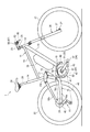
図1に示すように、電動補助自転車1は、ペダル33,34と電動モータ60とを有している。この電動補助自転車1は、運転者がペダル33,34を踏み込むことにより生じるペダルトルクと、電動モータ60から出力されるモータトルクとを合計した駆動トルクによって駆動される。電動モータ60のモータトルクが、運転者のペダル33,34の踏み込み動作をアシストする補助トルクとなる。また、この電動補助自転車1は、運転者がハンドル23を把持して押し歩きする際に、後輪22に電動モータ60が押し歩き補助トルクを付与可能である。
<Overall configuration of battery-assisted bicycle>
As shown in FIG. 1, the battery-assisted bicycle 1 includes
電動補助自転車1は、前後方向に延びる車体フレーム11を有する。また、電動補助自転車1は、前輪21、後輪22、ハンドル23、シート24及びパワーユニット40を有する。
The battery-assisted bicycle 1 has a body frame 11 extending in the front-rear direction. The battery-assisted bicycle 1 includes a
車体フレーム11は、ヘッドパイプ12、ダウンフレーム13、トップフレーム15、シートフレーム14、そしてシートフレーム14に上下揺動自在に懸架されたスイングアーム16を有する。ヘッドパイプ12は、電動補助自転車1の前部に配置される。ヘッドパイプ12には、後下方に延びるダウンフレーム13とトップフレーム15の前部が接続されている。シートフレーム14の下端部とダウンフレーム13の後部は車体前後方向に延在するブラケット19に接続されている。シートフレーム14は、ブラケット19の後端部から上方且つ斜め後方に向かって延びている。
The vehicle body frame 11 includes a
ヘッドパイプ12には、ハンドルステム25が回転自在に挿入されている。ハンドルステム25の上端部には、ハンドル23が固定されている。ハンドルステム25の下端部には、油圧緩衝器付のフロントフォーク26が固定されている。フロントフォーク26の下端部には、前輪21が車軸27によって回転可能に支持されている。フロントフォーク26の下端部には、前輪21の回転から車速を検出する前輪車速センサ37が設けられている。
A
円筒状のシートフレーム14の内方には、シートパイプ28が挿入されている。シートパイプ28の上端部には、シート24が設けられている。
A
スイングアーム16は一対のチェーンステイ16aと一対のシートステイ16bを一体化したものである。一対のチェーンステイ16aは、前端がシートフレーム14に第一の支軸16cを介して揺動自在に支持され、後輪22を左右から挟むように設けられている。一対のチェーンステイ16aは、第一の支軸16cから後輪22の回転中心に向かって延びている。シートフレーム14の中間部には、第二の支軸16d回りにリンク17が上下方向に揺動自在に支持されている。一対のシートステイ16bは、前端がリンク17を介してシートフレーム14に連結され、後端が後輪22の回転中心に向かって延びている。リンク17の他端とシートフレーム14との間には油圧緩衝器18が配置されている。チェーンステイ16aおよびシートステイ16bの後端部には、後輪22が回転可能に支持されている。
The
ダウンフレーム13には、パワーユニット40の電動モータ60に電力を供給するバッテリ35が載置されている。バッテリ35は、図示しない充放電可能な充電池及び電池制御部を有する。電池制御部は、充電池の充放電を制御するとともに、その出力電流及び残容量等を監視する。
A
パワーユニット40は、ユニットケース50に、クランク軸41、クランク回転入力軸(不図示)、ペダルトルク検出部57、クランク回転検出部58、電動モータ60および減速機(不図示)、合力出力軸59を組み込み、ユニット化したものである。パワーユニット40は、車体フレーム11のブラケット19にボルトで結合されている。
The
クランク軸41は、シートフレーム14の下方に回転可能に設けられている。クランク軸41はユニットケース50に左右方向に貫通して支持されている。クランク軸41の両端部にはクランクアーム31,32が取り付けられている。クランクアーム31,32の先端には、ペダル33,34が回転可能に取り付けられている。
The
クランク回転入力軸(不図示)は筒状に形成され、内部にクランク軸41が挿通される。クランク回転入力軸の一端はクランク軸41にスプライン結合され、他端は人力用一方向クラッチ(不図示)を介して合力出力軸59に結合される。
A crank rotation input shaft (not shown) is formed in a cylindrical shape, and a
ペダルトルク検出部57(トルクセンサの一例)は、クランク回転入力軸の周囲に配置され、運転者がペダル33,34を介してクランク軸41に入力したペダルトルクを検出する。
The pedal torque detector 57 (an example of a torque sensor) is disposed around the crank rotation input shaft, and detects pedal torque input by the driver to the
クランク回転検出部58は、運転者がペダル33,34を回転させたときのクランク回転入力軸またはこれに結合される人力用一方向クラッチの入力側の回転を検出する。
The
電動モータ60は、ユニットケース50内であって、クランク軸41の前方に配置されている。電動モータ60の回転は減速機(不図示)、モータ用一方向クラッチ(不図示)を介して、合力出力軸59に伝えられる。
The
駆動スプロケット42は、クランク軸41と同軸円筒状の合力出力軸59の右端に取り付けられている。この駆動スプロケット42はクランク軸41とともに回転する。従動スプロケット45は、後輪22の後輪軸29と同軸に複数段設けられている。従動スプロケット45は、図示せぬ一方向クラッチを介して後輪22に連結される。
The
無端状のチェーン46は、駆動スプロケット42と複数段の従動スプロケット45の何れかにリヤディレーラ51を介して掛け渡されている。これにより、運転者がペダル33,34を踏み込むと、合力出力軸59とともに駆動スプロケット42が回転する。さらに駆動スプロケット42の回転はチェーン46を介して従動スプロケット45に伝達され、後輪22が駆動される。
The
電動モータ60は、ユニットケース50内であって、クランク軸41の前方に配置されている。電動モータ60にはバッテリ35から電力が供給される。電動モータ60に電力を供給すると電動モータ60が回転する。電動モータ60の回転は、合力出力軸59上で人力と合力され、駆動スプロケット42を介してチェーン46に伝達される。このように、電動モータ60に電力を供給すると、電動モータ60にモータトルクが生じる。このモータトルクはチェーン46を介して後輪22に伝達される。
The
ハンドル23の左右端部にはグリップ部63が設けられている。グリップ部63は略左右方向に延びている。運転者は、これらのグリップ部63を把持可能である。
グリップ部63の近傍には、ブレーキレバー65が設けられている。運転者が右手で、右側のブレーキレバー65を操作すると、前輪21に制動力が付与される。運転者が左手で、左側のブレーキレバー65を操作すると、後輪22に制動力が付与される。
A
グリップ部63の近傍に操作部56が設けられている。操作部56は、グリップ部63を握る運転者の手指によって操作可能とされている。操作部56は、信号線(図示略)を介して、後述するモータ制御部95を含む制御装置100に接続されている。
An
このような電動補助自転車1は、制御装置100によって電動モータ60を制御し、後輪22にモータトルクを作用させる。
In such a battery-assisted bicycle 1, the
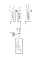
図2は、電動補助自転車1の機能を示すブロック図である。図2に示すように、制御装置100は、ペダルトルク算出部101、モータ制御部95、モータ駆動部105、変速段推定部97及びメモリ98を備えている。操作部56は、モータ制御部95に接続されている。
FIG. 2 is a block diagram showing functions of the battery-assisted bicycle 1. As shown in FIG. 2, the
<動力の伝達経路>
次に、動力の伝達経路について説明する。
運転者がペダル33,34を踏み込んでクランク軸41を回転させると、そのクランク軸41の回転が一方向クラッチ55を介して合力出力軸59に伝達される。一方向クラッチ55は、クランク軸41の順回転のみを合力出力軸59に伝達し、クランク軸41の逆回転は合力出力軸59に伝達させない。合力出力軸59の回転はチェーン46へ伝達される。
<Power transmission path>
Next, the power transmission path will be described.
When the driver steps on the
チェーン46の回転は後輪22側のリヤディレーラ51により所望の従動スプロケット45に伝達される。従動スプロケット45の回転は、一方向クラッチ92を介して後輪22に伝達される。
The rotation of the
リヤディレーラ51は運転者によって操作される変速操作器93に応じて変速段を変更できる機構である。変速操作器93には、変速段センサ94が設けられ、変速段センサ94は、変速操作器93における段数の情報を変速段推定部97へ送信する。
一方向クラッチ92は、従動スプロケット45の回転速度が後輪22の回転速度よりも速い場合にのみ、従動スプロケット45の回転を後輪22に伝える。従動スプロケット45の回転速度が後輪22の回転速度よりも遅い場合には、一方向クラッチ92は従動スプロケット45の回転を後輪22に伝えない。一方向クラッチ92には、後輪車速センサ96が設けられ、後輪車速センサ96は、後輪22の回転速度の情報を変速段推定部97へ送信する。
The
The one-way clutch 92 transmits the rotation of the driven
電動モータ60の回転は、減速機82を介して一方向クラッチ85に伝達される。一方向クラッチ85は、減速機82が合力出力軸59を順回転させる方向の回転のみを合力出力軸59に伝達し、減速機82が合力出力軸59を逆回転させる方向の回転は合力出力軸59に伝達させない。
The rotation of the
このように本実施形態に係る電動補助自転車1においては、クランク軸41に入力されるペダルトルクと電動モータ60のモータトルクは、合力出力軸59で合成されチェーン46へ伝達される。
Thus, in the battery-assisted bicycle 1 according to the present embodiment, the pedal torque input to the
<信号の経路>
次に、信号の経路を説明する。
運転者がクランク軸41を回転させると、車両に設けられたペダルトルク検出部57が、クランク軸41に入力されたペダルトルクに応じた信号を発生させる。ペダルトルク検出部57は、その信号をペダルトルク算出部101に入力する。
<Signal path>
Next, signal paths will be described.
When the driver rotates the
ペダルトルク算出部101は、ペダルトルク検出部57からの信号を運転者がペダル33,34に与えたペダルトルクに換算する。ペダルトルク算出部101は、そのペダルトルクの値をモータ制御部95に入力する。
The pedal
クランク回転検出部58は、クランク軸41の位相を検出するセンサである。クランク回転検出部58は、クランク軸41の位相に応じた信号を発生させる。クランク回転検出部58は、その信号をモータ制御部95に入力する。
The
前輪車速センサ37は、変速段推定部97に前輪21の回転速度の信号を送信する。変速段推定部97は、前輪21の回転速度から変速段を推定し、その情報をモータ制御部95へ送信する。
The front
電動モータ60には、モータ回転センサ99が設けられている。このモータ回転センサ99は、電動モータ60の回転数を検知し、変速段推定部97及びモータ駆動部105へ送信する。
The
<走行アシスト>
モータ制御部95は、ペダルトルク算出部101、クランク回転検出部58及び変速段推定部97からの出力、メモリ98に格納されている情報からの出力などから、適切なアシスト力を付与するための指令値を算出し、モータ駆動部105へ送信する。
<Running assist>
The
モータ駆動部105は、モータ制御部95からの指令値に基づいて、その指令値に応じた電力をバッテリ35から電動モータ60に供給する。これにより、電力が供給された電動モータ60が駆動し、所定のモータトルクを発生させる。
このように、モータ制御部95は、走行時の運転者のペダル33,34を漕ぐ動作をアシストするように、電動モータ60にモータトルクを発生させることができる。
Based on the command value from the
In this way, the
上記構成の電動補助自転車1は、モータ制御部95が、第一制御または第二制御に基づいて指令値を決定する。第二制御は、第一制御に対して、ペダルトルクの変動に対するアシストトルクの変動に要する時間が短く、かつ、ペダルトルクの変動に対するアシストトルクの変動量が大きい。
In the battery-assisted bicycle 1 configured as described above, the
図3は、実施形態に係る電動補助自転車1の操作部56の操作による制御の切り替わり動作を示すフローチャートである。図3に示すように、電動補助自転車1では、車両の電源ON後は、第一制御が選択されている(step1)。この第一制御が選択された状態において、運転者によって操作部56が操作されると、第二制御が選択される(step2)。また、この第二制御が選択された状態において、運転者によって操作部56が操作されると、第一制御が選択される(step1)。
このため、例えば、通常時は第一制御が選択されており、発進時、段差乗り越え時等の瞬間的なアシストが欲しい場合に、操作部56を操作して第二制御を選択することで、スムーズな発進や段差乗り越えができるようにアシストトルクを得ることができる。
FIG. 3 is a flowchart showing the control switching operation by the operation of the
For this reason, for example, the first control is normally selected, and when instantaneous assistance such as starting, stepping over a step, etc. is desired, by operating the
図4は、モータ制御部95による制御の切り替えを説明する模式図である。
図4に示すように、モータ制御部95は、操作部56が操作されることで、第一制御から第二制御へまたは第二制御から第一制御へ切り替える。モータ制御部95は、ペダルトルクの値P(t)、ペダルトルクの平均値PA(t)、クランク速度c、車速v等に基づいて、アシストトルクに応じた指令値を算出する。
FIG. 4 is a schematic diagram for explaining control switching by the
As shown in FIG. 4, the
次に、第一制御及び第二制御におけるモータ制御部95からモータ駆動部105へ送信される指令値の算出例について説明する。
Next, an example of calculating command values transmitted from the
モータ制御部95は、基本的には、時刻tのペダルトルクP(t)に応じたアシストトルクの成分を算出し、時刻tにおけるペダルトルクの平均値PA1(t)に応じたアシストトルクの成分を算出し、両方のアシストトルクの成分を合計して時刻tにおけるアシストトルクT(t)を定める。
The
モータ制御部95は、第一制御または、第一制御とは異なる第二制御に従って、アシストトルクを算出する。モータ制御部95は、アシストトルクに応じた指令値を算出し、指令値をモータ駆動部105に送信する。
The
第一制御では、以下の式(1)に基づいてアシストトルクT1(t)を算出する。
T1(t)={a×P(t)×α+b×PA1(t)×(1−α)}×A1・・・(1)
ここで、
P(t)は、現在時刻tにおけるペダルトルク、
PA1(t)は、スパン(t−t1)の間のペダルトルクの平均値、
a,b,A1は、定数、
αは、0≦α≦1の変数、である。
In the first control, the assist torque T1 (t) is calculated based on the following formula (1).
T1 (t) = {a * P (t) * [alpha] + b * PA1 (t) * (1- [alpha])} * A1 (1)
here,
P (t) is the pedal torque at the current time t,
PA1 (t) is an average value of the pedal torque during the span (t−t1),
a, b and A1 are constants,
α is a variable of 0 ≦ α ≦ 1.
第二制御では、以下の式(2)に基づいてアシストトルクT2(t)を算出する。
T2(t)={e×P(t)×β+f×PA2(t)×(1−β)}×A2・・・(2)
ここで、
P(t)は、現在時刻tにおけるペダルトルク、
PA2(t)は、スパン(t−t2)の間のペダルトルクの平均値、
t1,t2について、|t−t2|≦|t−t1|であり、
e,f,A2は、定数、(a/b<e/f)
βは、0≦β≦1の変数、α<β
である。
In the second control, the assist torque T2 (t) is calculated based on the following equation (2).
T2 (t) = {e × P (t) × β + f × PA2 (t) × (1-β)} × A2 (2)
here,
P (t) is the pedal torque at the current time t,
PA2 (t) is an average value of pedal torque during the span (t−t2),
For t1 and t2, | t−t2 | ≦ | t−t1 |
e, f, and A2 are constants, (a / b <e / f)
β is a variable of 0 ≦ β ≦ 1, α <β
It is.
ここで、ペダルトルクの平均値について、第一制御と第二制御とで、平均値を得るためのスパンが異なっている。|t−t2|<|t−t1|である場合には、第一制御で用いるペダルトルクの平均値PA1(t)は、第二制御で用いるペダルトルクの平均値PA2(t)よりも、ペダルトルクP(t)の変動に対するアシストトルクの変動に要する時間が長くなる傾向を有する。 Here, regarding the average value of the pedal torque, the span for obtaining the average value is different between the first control and the second control. When | t−t2 | <| t−t1 |, the average value PA1 (t) of the pedal torque used in the first control is larger than the average value PA2 (t) of the pedal torque used in the second control. There is a tendency that the time required for the variation of the assist torque with respect to the variation of the pedal torque P (t) becomes longer.
なお、t1=t2であってもよい。この場合には|t−t2|=|t−t1|である。
α<β、かつ、(a/b<e/f)であるため
第一制御において、ペダルトルクに基づいて算出されるアシストトルクの成分とペダルトルクの平均値に基づいて算出されるアシストトルクの成分との比率k1=(a×P(t)×α)/{b×PA1(t)×(1−α)}と、
第二制御において、ペダルトルクに基づいて算出されるアシストトルクの成分とペダルトルクの平均値に基づいて算出されるアシストトルクの成分との比率k2=(e×P(t)×β)/{f×PA2(t)×(1−β)}と、
を比較すると、k1<k2である。
It may be t1 = t2. In this case, | t−t2 | = | t−t1 |.
Since α <β and (a / b <e / f), in the first control, the assist torque component calculated based on the pedal torque and the average value of the assist torque calculated based on the pedal torque Ratio k1 = (a × P (t) × α) / {b × PA1 (t) × (1-α)}
In the second control, the ratio of the assist torque component calculated based on the pedal torque and the assist torque component calculated based on the average value of the pedal torque k2 = (e × P (t) × β) / { f × PA2 (t) × (1-β)},
Are k1 <k2.
つまり、第二制御は、第一制御よりも、時刻tにおけるペダルトルク(の瞬間値)P(t)に応じて算出されるアシストトルクの成分がペダルトルクの平均値PA1(t),PA2(t)に応じて算出されるアシストトルクの成分よりも大きい傾向を有する。このため、t1=t2であってPA1(t)=PA2(t)であっても、第二制御によれば、ペダルトルクの変動に応じて素早くアシストトルクを変動させやすい。 That is, in the second control, the assist torque component calculated according to the pedal torque (instantaneous value) P (t) at time t is greater than the first control in the pedal torque average values PA1 (t), PA2 ( It tends to be larger than the assist torque component calculated according to t). For this reason, even if t1 = t2 and PA1 (t) = PA2 (t), according to the second control, the assist torque can be easily changed according to the change in the pedal torque.
またk1<k2であるため、ペダルトルクP(t)が変動した場合、その変化量は、ペダルトルクの平均値の変動量よりも大きくなる。このため、第二制御は第一制御よりも、ペダルトルクの変動に対するアシストトルクの変動量が大きくなる。 Further, since k1 <k2, when the pedal torque P (t) varies, the variation amount is larger than the variation amount of the average value of the pedal torque. For this reason, the variation amount of the assist torque with respect to the variation of the pedal torque is larger in the second control than in the first control.
なお、上述した例においては、アシストトルクの指令値T1,T2を、ペダルトルクの時間的な平均値に基づいて算出する例を説明したが、本発明は、これに限らない。例えば、次に式(3),(4)を用いて説明するように、クランク軸41の所定回転あたりのペダルトルクの平均値に基づいて、アシストトルクの指令値T1,T2を算出してもよい。
In the example described above, the assist torque command values T1 and T2 are calculated based on the temporal average value of the pedal torque. However, the present invention is not limited to this. For example, the assist torque command values T1 and T2 may be calculated based on the average value of the pedal torque per predetermined rotation of the
第一制御では、以下の式(3)に基づいてアシストトルクT1(t)を算出する。
T1(t)={a×P(t)×α+b×QA1(t)×(1−α)}×A1・・・(3)
ここで、
P(t)は、現在時刻tにおけるペダルトルク、
QA1(t)は、現在時刻tにおけるクランク軸41の過去1/g周分のペダルトルクの平均値
a,b,A1は、定数、
αは、0≦α≦1の変数、である。
In the first control, the assist torque T1 (t) is calculated based on the following equation (3).
T1 (t) = {a × P (t) × α + b × QA1 (t) × (1-α)} × A1 (3)
here,
P (t) is the pedal torque at the current time t,
QA1 (t) is an average value a, b, A1 of the pedal torque for the past 1 / g of the
α is a variable of 0 ≦ α ≦ 1.
第二制御では、以下の式(4)に基づいてアシストトルクT2(t)を算出する。
T2(t)={e×P(t)×β+f×QA2(t)×(1−β)}×A2・・・(4)
ここで、
P(t)は、現在時刻tにおけるペダルトルク、
QA2(t)は、現在時刻tにおけるクランク軸41の過去1/h(g≦h)周分のペダルトルクの平均値
e,f,A2は、定数、(a/b<e/f)
βは、0≦β≦1の変数、α<β
である。
In the second control, the assist torque T2 (t) is calculated based on the following equation (4).
T2 (t) = {e × P (t) × β + f × QA2 (t) × (1-β)} × A2 (4)
here,
P (t) is the pedal torque at the current time t,
QA2 (t) is the average pedal torque e, f, A2 for the past 1 / h (g ≦ h) of the
β is a variable of 0 ≦ β ≦ 1, α <β
It is.
例えば、第一制御においてはg=1として、クランク軸41の1回転あたりのペダルトルクの平均値からアシストトルクT1(t)を算出し、第二制御においてはh=2として、クランク軸41の半回転あたりのペダルトルクの平均値からアシストトルクT2(t)を算出するように構成してもよい。
この場合においても、第二制御は、第一制御に対して、ペダルトルクの変動に対するアシストトルクの変動に要する時間が短い。かつ、第二制御は、第一制御に対して、ペダルトルクの変動に対するアシストトルクの変動量が大きくなる。
For example, the assist torque T1 (t) is calculated from the average value of the pedal torque per rotation of the
Even in this case, the second control requires a shorter time to change the assist torque relative to the pedal torque than the first control. In addition, in the second control, the amount of change in assist torque with respect to the change in pedal torque is greater than in the first control.
なお、上式(1)〜(4)において、α,βは以下のようにして設定することができる。
モータ制御部95は、ペダルトルクの変動から算出したクランク速度cもしくはクランク回転検出部58の出力から算出したクランク速度cに基づいて、クランク速度cが小さいほどαおよびβを大きく、クランク速度cが大きいほどαおよびβを小さく設定してもよい。
In the above formulas (1) to (4), α and β can be set as follows.
Based on the crank speed c calculated from the pedal torque fluctuation or the crank speed c calculated from the output of the
あるいは、モータ制御部95は、前輪車速センサ37や後輪車速センサ96などの車輪速センサの出力から算出した車輪速vに基づいて、車輪速vが小さいほどαおよびβを大きく、車輪速vが大きいほどαおよびβを小さく設定してもよい。
Or, based on the wheel speed v calculated from the output of the wheel speed sensor such as the front wheel
さらに、モータ制御部95は、α,βを、クランク速度cと車輪速vに基づいて、クランク速度cが小さいほどαおよびβを大きく、クランク速度cが大きいほどαおよびβを小さく、車輪速vが小さいほどαおよびβを大きく、車輪速vが大きいほどαおよびβを小さく設定してもよい。
Further, the
このように、クランク速度c及び車輪速vの何れか一方、または、クランク速度c及び車輪速vの両方に応じてαおよびβを大きくまたは小さく設定することで、発進時に力強いアシストトルクが素早く得られたり、巡航速度で走行するときに滑らかなアシストトルクが得られたりするなど、状況に応じた適切なアシストトルクが得られる。 In this way, by setting α and β large or small according to either the crank speed c and the wheel speed v or both the crank speed c and the wheel speed v, a powerful assist torque can be quickly obtained at the time of start. Appropriate assist torque according to the situation can be obtained, for example, smooth assist torque can be obtained when traveling at a cruise speed.
定数a,b,e,f,A1,A2は、例えばメモリ98に記録されたプリセットされた値である。あるいは、ユーザがa,b,e,f,A1,A2を変更可能に構成してもよい。aとeは互いに等しくても異なっていてもよい。bとfは互いに等しくても異なっていてもよい。A1とA2は互いに等しくても異なっていてもよい。 The constants a, b, e, f, A1, and A2 are preset values recorded in the memory 98, for example. Or you may comprise so that a user can change a, b, e, f, A1, and A2. a and e may be equal to or different from each other. b and f may be equal to or different from each other. A1 and A2 may be equal to or different from each other.
本実施形態によれば、第一制御と、第一制御とは運転者が感じるアシスト感が異なる第二制御とにより、アシストトルクが電動モータ60から出力される。
According to the present embodiment, the assist torque is output from the
第二制御は第一制御よりもペダルトルクの変動に対して迅速にアシストトルクを変動させ、かつ、ペダルトルクの変動に対するアシストトルクの変動量が大きい。このため、例えば、ユーザが走り出しの際に第二制御を選択することにより、ペダルトルクを入力したらすぐにアシストトルクが得られ、かつ入力したペダルトルクに応じて力強いアシストトルクが得られる。 The second control varies the assist torque more quickly with respect to the pedal torque variation than the first control, and the variation amount of the assist torque with respect to the pedal torque variation is larger. For this reason, for example, by selecting the second control when the user starts running, the assist torque is obtained as soon as the pedal torque is input, and a strong assist torque is obtained according to the input pedal torque.
第一制御は第二制御よりも、ペダルトルクの変動に対するアシストトルクの変動に要する時間が長く、かつペダルトルクの変動に対するアシストトルクの変動量が小さい。したがって、アシストトルクがペダルトルクの変動により変動しにくいため、例えば、ユーザが巡航速度で走行する際に第一制御を選択することにより、快適なアシスト感が得られる。 The first control requires a longer time for the assist torque variation with respect to the pedal torque variation and the assist torque variation amount with respect to the pedal torque variation is smaller than the second control. Therefore, the assist torque is unlikely to fluctuate due to fluctuations in the pedal torque. For example, a comfortable assist feeling can be obtained by selecting the first control when the user travels at the cruising speed.
このように、本実施形態に係る電動補助自転車1によれば、電動モータ60の出力特性の幅が広いので、ユーザの利便性が高められている。
あるいは、例えば、ユーザは、ダウンヒルコース等で、段差の少ない登坂路を、連続的にアシスト走行する際は、第一制御を実行し、頂上到達後、下る際は第二制御に切り替え、応答性の高いアシストでよりクイックな走行を実現することができる。
Thus, according to the battery-assisted bicycle 1 according to the present embodiment, the output characteristics of the
Alternatively, for example, when the user continuously assists on an uphill road with a small step on a downhill course or the like, the first control is executed, and after reaching the top, the user switches to the second control when going down and is responsive. A quicker driving can be realized with high assist.
なお、上記の説明では、アシストトルクをペダルトルクとペダルトルクの平均値から算出する例を説明したが、本発明はこれに限られない。アシストトルクをペダルトルクとペダルトルクの平均値の他に、車速やクランク回転数に応じて算出するように構成してもよい。 In the above description, the assist torque is calculated from the average value of the pedal torque and the pedal torque. However, the present invention is not limited to this. The assist torque may be calculated according to the vehicle speed and the crank rotation speed in addition to the pedal torque and the average value of the pedal torque.
また、モータ制御部95は、車両の走行中に第一制御と第二制御とを切り替える際に、現在の指令値と切替後の算出された指令値との変動量が所定の上限値を超える場合に、算出された指令値に代えて所定の上限値に設定しても良い。
このように制御することで、指令値の変動量を抑えることができ、第一制御と第二制御とを円滑に切り替えることができる。
Further, when the
By controlling in this way, the fluctuation amount of the command value can be suppressed, and the first control and the second control can be smoothly switched.
また、電動補助自転車1に、図1に示したように、モータ制御部95が第一制御または第二制御を実行中であることに応じて異なる色もしくは異なるパターンで光る表示器67を設けても良い。ここで異なるパターンとは消灯・点灯・点滅のうちの任意の2パターンである。
このような表示器67を設けることで、ユーザは、表示器67を視認することで、現在実行されている制御が第一制御または第二制御のいずれであるかを容易に確認することができる。表示器67の発光状態は、ユーザが注視しなくても容易に把握可能である。このため、ダウンヒルなどの起伏が激しい走行路を走行中に、頻繁に第一制御と第二制御とを切り替える際などに、好適である。
Further, as shown in FIG. 1, the battery-assisted bicycle 1 is provided with a
By providing such a
なお、上記実施形態では、ユーザが操作部56を操作することで、第一制御及び第二制御が順に切り替わる構成としたが、第一制御及び第二制御の切り替えの方式としては、上記の例に限定されない。
例えば、ユーザが操作部56を操作している間だけ(ボタンを押している間やレバーを握っている間だけ)第二制御を実行し、ユーザが操作部56を操作していない間だけ第一制御を実行するように構成してもよい。
In the above-described embodiment, the first control and the second control are sequentially switched when the user operates the
For example, the second control is executed only while the user operates the operation unit 56 (only while the button is pressed or the lever is held), and the first control is performed only while the user is not operating the
また、車両の電源ON後は第一制御が選択されており、ユーザが操作部56を操作することにより、第二制御が選択されるようにし、該操作の以降は操作部56が再び操作されるまで、第二制御が選択されるように構成してもよい。
また、車両の電源がOFFにされるとリセットされて、次の電源ON後は第一制御が選択されるように構成してもよい。あるいは、車両の電源がOFFにされても、再び操作部56が操作されるまでは、次の電源のONの後も第二制御が選択されるように構成してもよい。
In addition, the first control is selected after the vehicle is turned on, and the user operates the
Further, it may be configured to be reset when the power of the vehicle is turned off and to select the first control after the next power-on. Alternatively, even if the power of the vehicle is turned off, the second control may be selected even after the next power is turned on until the
さらには、操作部56は、ボタンやスイッチなどの電気式の操作盤の操作による、モードの選択であってもよいし、スマートフォンからのアシスト方式の選択信号を受信するように構成してもよい。
なお、操作部56は、レバーやトグル、ボタン、スイッチなど機械式の構成であってもよい。例えば、スイッチがそのポジションにある限り、電源ON/OFFに関わらず第一制御/第二制御の選択が保持されるようにしても良い。
Furthermore, the
The
また、本実施形態に係る電動補助自転車1としては、モータ制御部95が走行時の運転者のペダルトルクをアシストするほかに、押し歩き時に運転者の押し歩き動作を補助する押し歩き補助トルクを電動モータ60に出力させる押し歩き機能を搭載しても良い。このような押し歩きアシスト機能を車両に搭載する場合には、押し歩き補助トルクを発生させる押し歩き操作部と、第一制御/第二制御を選択する操作部とを別々に搭載してもよい。あるいは、単一の操作部を搭載し、操作部の1回押しで第一制御または第二制御の選択をし、長押しで押し歩き補助トルクを発生させるように構成してもよい。
Further, as the battery-assisted bicycle 1 according to the present embodiment, in addition to assisting the driver's pedal torque during traveling by the
1:電動補助自転車、11:車体フレーム、12:ヘッドパイプ、13:ダウンフレーム、14:シートフレーム、15:トップフレーム、16:スイングアーム、16a:チェーンステイ、16b:シートステイ、16c:第一の支軸、17:リンク、18:油圧緩衝器、19:ブラケット、21:前輪(車輪)、22:後輪(車輪)、23:ハンドル、24:シート、25:ハンドルステム、26:フロントフォーク、27:車軸、28:シートパイプ、29:後輪軸、31:クランクアーム、32:クランクアーム、33:ペダル、34:ペダル、35:バッテリ、37:前輪車速センサ(車輪速センサ)、40:パワーユニット、41:クランク軸、42:駆動スプロケット、45:従動スプロケット、46:チェーン、50:ユニットケース、51:リヤディレーラ、55:一方向クラッチ、56:操作部、57:ペダルトルク検出部(トルクセンサ)、58:クランク回転検出部、59:合力出力軸、60:電動モータ、63:グリップ部、65:ブレーキレバー、67:表示器、82:減速機、85:一方向クラッチ、92:一方向クラッチ、93:変速操作器、94:変速段センサ、95:モータ制御部(制御部)、96:後輪車速センサ(車輪速センサ)、97:変速段推定部、98:メモリ、99:モータ回転センサ、100:制御装置、101:ペダルトルク算出部、105:モータ駆動部 1: battery-assisted bicycle, 11: body frame, 12: head pipe, 13: down frame, 14: seat frame, 15: top frame, 16: swing arm, 16a: chain stay, 16b: seat stay, 16c: first 17: Link, 18: Hydraulic shock absorber, 19: Bracket, 21: Front wheel (wheel), 22: Rear wheel (wheel), 23: Handle, 24: Seat, 25: Handle stem, 26: Front fork 27: axle, 28: seat pipe, 29: rear axle, 31: crank arm, 32: crank arm, 33: pedal, 34: pedal, 35: battery, 37: front wheel vehicle speed sensor (wheel speed sensor), 40: Power unit 41: Crankshaft 42: Drive sprocket 45: Driven sprocket 46: Chain 50: Uni 51: Rear derailleur, 55: One-way clutch, 56: Operation unit, 57: Pedal torque detection unit (torque sensor), 58: Crank rotation detection unit, 59: Combined force output shaft, 60: Electric motor, 63: Grip , 65: Brake lever, 67: Indicator, 82: Reducer, 85: One-way clutch, 92: One-way clutch, 93: Shifting actuator, 94: Shift speed sensor, 95: Motor control unit (control unit) 96: Rear wheel speed sensor (wheel speed sensor), 97: Shift speed estimation unit, 98: Memory, 99: Motor rotation sensor, 100: Control device, 101: Pedal torque calculation unit, 105: Motor drive unit
Claims (7)
前記クランク軸を回転させるペダルと、
運転者が前記ペダルを踏む力をアシストする電動モータを有する電動補助自転車であって、
運転者の前記ペダルへのペダルトルクに応じた信号を出力するトルクセンサと、
少なくとも前記トルクセンサの出力に基づいて、アシストトルクの大きさを決定する指令値を算出する制御部と、
運転者が操作可能な操作部と、を備え、
前記制御部は、運転者の前記操作部の操作に応じて、
第一制御と、
前記第一制御に対して、前記ペダルトルクの変動に対する前記アシストトルクの変動に要する時間が短く、かつ、前記ペダルトルクの変動に対する前記アシストトルクの変動量が大きい第二制御と、を切り替え可能に構成されている、電動補助自転車。 A crankshaft,
A pedal for rotating the crankshaft;
A battery-assisted bicycle having an electric motor for assisting a driver to step on the pedal,
A torque sensor that outputs a signal corresponding to the pedal torque to the pedal of the driver;
A control unit that calculates a command value for determining the magnitude of the assist torque based on at least the output of the torque sensor;
An operation unit operable by the driver,
According to the operation of the operation unit of the driver, the control unit,
The first control,
It is possible to switch between the first control and the second control in which the time required for the assist torque variation with respect to the pedal torque variation is short and the assist torque variation amount with respect to the pedal torque variation is large. A motor-assisted bicycle that is configured.
現在時刻tにおけるペダルトルクの値P(t)、スパン(t−t1)の間のペダルトルクの平均値PA1(t)、スパン(t−t2,|t−t2|≦|t−t1|)の間のペダルトルクの平均値PA2(t)、定数a,b,e,f,A1,A2(a/b<e/f)、変数α,β(0≦α≦1,0≦β≦1,α<β)とすると、
前記第一制御により算出される指令値T1は、下記(1)式で算出し、
T1(t)={a×P(t)×α+b×PA1(t)×(1−α)}×A1・・・(1)
前記第二制御により算出される指令値T2は、下記(2)式で算出する、請求項1に記載の電動補助自転車。
T2(t)={e×P(t)×β+f×PA2(t)×(1−β)}×A2・・・(2) The controller is
Pedal torque value P (t) at the current time t, pedal torque average value PA1 (t) during span (t−t1), span (t−t2, | t−t2 | ≦ | t−t1 |) Pedal torque average value PA2 (t), constants a, b, e, f, A1, A2 (a / b <e / f), variables α, β (0 ≦ α ≦ 1, 0 ≦ β ≦) 1, α <β)
The command value T1 calculated by the first control is calculated by the following equation (1):
T1 (t) = {a * P (t) * [alpha] + b * PA1 (t) * (1- [alpha])} * A1 (1)
The battery-assisted bicycle according to claim 1, wherein the command value T2 calculated by the second control is calculated by the following equation (2).
T2 (t) = {e × P (t) × β + f × PA2 (t) × (1-β)} × A2 (2)
現在時刻tにおけるペダルトルクの値P(t)、現在時刻tにおける前記クランク軸の過去1/g周分のペダルトルクの平均値QA1(t)、現在時刻tにおける前記クランク軸の過去1/h(g≦h)周分のペダルトルクの平均値QA2(t)、定数a,b,e,f,A1,A2(a/b<e/f)、変数α,β(0≦α≦1,0≦β≦1,α<β)とすると、
前記第一制御により算出される指令値T1は、下記(3)式で算出し、
T1(t)={a×P(t)×α+b×QA1(t)×(1−α)}×A1・・・(3)
前記第二制御により算出される指令値T2は、下記(4)式で算出する、請求項1に記載の電動補助自転車。
T2(t)={e×P(t)×β+f×QA2(t)×(1−β)}×A2・・・(4) The controller is
The value P (t) of the pedal torque at the current time t, the average value QA1 (t) of the pedal torque for the past 1 / g of the crankshaft at the current time t, and the past 1 / h of the crankshaft at the current time t (G ≦ h) Pedal torque average value QA2 (t), constants a, b, e, f, A1, A2 (a / b <e / f), variables α, β (0 ≦ α ≦ 1) , 0 ≦ β ≦ 1, α <β)
The command value T1 calculated by the first control is calculated by the following equation (3):
T1 (t) = {a × P (t) × α + b × QA1 (t) × (1-α)} × A1 (3)
The battery-assisted bicycle according to claim 1, wherein the command value T2 calculated by the second control is calculated by the following equation (4).
T2 (t) = {e × P (t) × β + f × QA2 (t) × (1-β)} × A2 (4)
前記制御部は、前記車輪速センサの出力から算出した車輪速vに基づいて、前記車輪速vが小さいほどαおよびβを大きく、前記車輪速vが大きいほどαおよびβを小さく設定する、請求項2から4のいずれか一項に記載の電動補助自転車。 A wheel speed sensor that outputs a signal corresponding to the wheel speed of the wheel;
The control unit sets α and β larger as the wheel speed v is smaller, and α and β are smaller as the wheel speed v is larger, based on the wheel speed v calculated from the output of the wheel speed sensor. Item 5. The battery-assisted bicycle according to any one of items 2 to 4.
Priority Applications (3)
| Application Number | Priority Date | Filing Date | Title |
|---|---|---|---|
| JP2015234609A JP2017100540A (en) | 2015-12-01 | 2015-12-01 | Power-assisted bicycle |
| EP16201343.7A EP3176065B1 (en) | 2015-12-01 | 2016-11-30 | Electrically assisted bicycle |
| US15/364,372 US10173749B2 (en) | 2015-12-01 | 2016-11-30 | Electrically assisted bicycle |
Applications Claiming Priority (1)
| Application Number | Priority Date | Filing Date | Title |
|---|---|---|---|
| JP2015234609A JP2017100540A (en) | 2015-12-01 | 2015-12-01 | Power-assisted bicycle |
Publications (1)
| Publication Number | Publication Date |
|---|---|
| JP2017100540A true JP2017100540A (en) | 2017-06-08 |
Family
ID=57442544
Family Applications (1)
| Application Number | Title | Priority Date | Filing Date |
|---|---|---|---|
| JP2015234609A Pending JP2017100540A (en) | 2015-12-01 | 2015-12-01 | Power-assisted bicycle |
Country Status (3)
| Country | Link |
|---|---|
| US (1) | US10173749B2 (en) |
| EP (1) | EP3176065B1 (en) |
| JP (1) | JP2017100540A (en) |
Cited By (3)
| Publication number | Priority date | Publication date | Assignee | Title |
|---|---|---|---|---|
| JP2019038481A (en) * | 2017-08-29 | 2019-03-14 | パナソニックIpマネジメント株式会社 | Electrically driven tricycle |
| JP2019172214A (en) * | 2018-03-29 | 2019-10-10 | 株式会社シマノ | Controller for man-power drive vehicle |
| DE102021122286A1 (en) | 2020-09-03 | 2022-03-03 | Shimano Inc. | WHEEL SPEED SENSOR AND WHEEL SPEED SENSOR CLAMPING ARRANGEMENT |
Families Citing this family (9)
| Publication number | Priority date | Publication date | Assignee | Title |
|---|---|---|---|---|
| US9216791B2 (en) * | 2011-03-14 | 2015-12-22 | Christopher Hudec | Bicycle suspension system |
| JP2017013524A (en) * | 2015-06-26 | 2017-01-19 | ヤマハ発動機株式会社 | Power-assisted bicycle |
| US10507886B2 (en) * | 2016-07-29 | 2019-12-17 | Shimano Inc. | Bicycle controller |
| DE202017004040U1 (en) * | 2017-08-03 | 2018-11-06 | Canyon Bicycles Gmbh | E-bike bicycle frame |
| JP7146385B2 (en) * | 2017-11-15 | 2022-10-04 | 株式会社シマノ | Control device for human-powered vehicle |
| CN108284913A (en) * | 2018-01-30 | 2018-07-17 | 世同金属(昆山)有限公司 | A kind of moment sensing electric assisted bicycle |
| TWI770430B (en) * | 2019-10-24 | 2022-07-11 | 英屬開曼群島商睿能創意公司 | Electronic bicycle, transmission device, and operation method |
| JP7039545B2 (en) * | 2019-12-27 | 2022-03-22 | ヤマハ発動機株式会社 | Electric auxiliary bicycle, its drive system, and control method |
| DE102022118220B3 (en) * | 2022-07-21 | 2023-12-07 | Jochen Klieber | Method for controlling an electric drive of a two-wheeler and control device for carrying out the method and two-wheeler |
Citations (6)
| Publication number | Priority date | Publication date | Assignee | Title |
|---|---|---|---|---|
| JPH07187054A (en) * | 1993-10-29 | 1995-07-25 | Yamaha Motor Co Ltd | Vehicle with electric motor |
| JPH10114292A (en) * | 1996-10-11 | 1998-05-06 | Tec Corp | Bicycle with electric assist power unit |
| WO2012086458A1 (en) * | 2010-12-22 | 2012-06-28 | マイクロスペース株式会社 | Motor drive control device |
| JP2014208522A (en) * | 2013-03-29 | 2014-11-06 | ヤマハ発動機株式会社 | Control device for electric bicycle, power unit for electric bicycle, and electric bicycle |
| JP2015112994A (en) * | 2013-12-11 | 2015-06-22 | ブリヂストンサイクル株式会社 | Bicycle with electric motor |
| JP2015182600A (en) * | 2014-03-24 | 2015-10-22 | ブリヂストンサイクル株式会社 | Power-assisted bicycle |
Family Cites Families (10)
| Publication number | Priority date | Publication date | Assignee | Title |
|---|---|---|---|---|
| CN1095984C (en) * | 1995-10-17 | 2002-12-11 | 精工爱普生株式会社 | Sensor device, driving force supplementing device and zero point adjusting device for torque sensor for driving force supplementing device |
| JP2001080569A (en) * | 1999-09-17 | 2001-03-27 | Sanyo Electric Co Ltd | Vehicle with auxiliary motive power |
| JP2001122184A (en) | 1999-10-29 | 2001-05-08 | Sanyo Electric Co Ltd | Vehicle with auxiliary power |
| JP2006015887A (en) | 2004-07-02 | 2006-01-19 | Sanyo Electric Co Ltd | Motor-assisted bicycle |
| JP2013121797A (en) | 2011-12-12 | 2013-06-20 | Honda Motor Co Ltd | Power-assisted bicycle |
| CN105667693B (en) | 2014-12-05 | 2018-08-10 | 株式会社岛野 | Bicycle control |
| JP6277157B2 (en) | 2015-07-24 | 2018-02-07 | 株式会社シマノ | Bicycle control device |
| CN107428393B (en) * | 2015-02-13 | 2020-05-15 | 斯沃莱茨德塞格尔公司 | Electric bicycle transmission system, method and apparatus |
| JP6295223B2 (en) * | 2015-03-20 | 2018-03-14 | 株式会社シマノ | Shift control device |
| FR3035712B1 (en) * | 2015-04-30 | 2018-07-06 | Continental Automotive France | TORQUE MEASUREMENT DEVICE APPLIED TO ROTARY SHAFT AND ASSOCIATED TORQUE MEASUREMENT METHOD |
-
2015
- 2015-12-01 JP JP2015234609A patent/JP2017100540A/en active Pending
-
2016
- 2016-11-30 US US15/364,372 patent/US10173749B2/en active Active
- 2016-11-30 EP EP16201343.7A patent/EP3176065B1/en active Active
Patent Citations (6)
| Publication number | Priority date | Publication date | Assignee | Title |
|---|---|---|---|---|
| JPH07187054A (en) * | 1993-10-29 | 1995-07-25 | Yamaha Motor Co Ltd | Vehicle with electric motor |
| JPH10114292A (en) * | 1996-10-11 | 1998-05-06 | Tec Corp | Bicycle with electric assist power unit |
| WO2012086458A1 (en) * | 2010-12-22 | 2012-06-28 | マイクロスペース株式会社 | Motor drive control device |
| JP2014208522A (en) * | 2013-03-29 | 2014-11-06 | ヤマハ発動機株式会社 | Control device for electric bicycle, power unit for electric bicycle, and electric bicycle |
| JP2015112994A (en) * | 2013-12-11 | 2015-06-22 | ブリヂストンサイクル株式会社 | Bicycle with electric motor |
| JP2015182600A (en) * | 2014-03-24 | 2015-10-22 | ブリヂストンサイクル株式会社 | Power-assisted bicycle |
Cited By (4)
| Publication number | Priority date | Publication date | Assignee | Title |
|---|---|---|---|---|
| JP2019038481A (en) * | 2017-08-29 | 2019-03-14 | パナソニックIpマネジメント株式会社 | Electrically driven tricycle |
| JP2019172214A (en) * | 2018-03-29 | 2019-10-10 | 株式会社シマノ | Controller for man-power drive vehicle |
| US11377166B2 (en) | 2018-03-29 | 2022-07-05 | Shimano Inc. | Human-powered vehicle control device |
| DE102021122286A1 (en) | 2020-09-03 | 2022-03-03 | Shimano Inc. | WHEEL SPEED SENSOR AND WHEEL SPEED SENSOR CLAMPING ARRANGEMENT |
Also Published As
| Publication number | Publication date |
|---|---|
| US20170151998A1 (en) | 2017-06-01 |
| US10173749B2 (en) | 2019-01-08 |
| EP3176065A3 (en) | 2017-07-26 |
| EP3176065A2 (en) | 2017-06-07 |
| EP3176065B1 (en) | 2020-06-10 |
Similar Documents
| Publication | Publication Date | Title |
|---|---|---|
| JP2017100540A (en) | Power-assisted bicycle | |
| JP5986150B2 (en) | Bicycle control device, electric assist bicycle including the bicycle control device, and motor control method for electric assist bicycle | |
| US9896156B2 (en) | Gear changing control apparatus | |
| JP6811011B2 (en) | Electric auxiliary bicycle | |
| US8958935B2 (en) | Bicycle drive apparatus | |
| EP3109089B1 (en) | Electrically assisted bicycle | |
| TW201637933A (en) | Bicycle motor control system | |
| JP6325596B2 (en) | Bicycle control device and electric assist bicycle including bicycle control device | |
| JP6193931B2 (en) | Bicycle control device | |
| EP2783970B1 (en) | Controller for electric bicycle, power unit for electric bicycle, and electric bicycle | |
| JP6941541B2 (en) | Control device for human-powered vehicles | |
| EP3533700B1 (en) | Assist force calculation method for an electrically assisted bicycle, electrically assisted bicycle control unit, electrically assisted bicycle power unit, and electrically assisted bicycle | |
| JP5255347B2 (en) | Vehicle with assist power | |
| JP7277120B2 (en) | Control device for man-powered vehicles | |
| JP6562717B2 (en) | Electric assist bicycle | |
| JP3832688B2 (en) | Automatic transmission control device and battery-assisted bicycle using the same | |
| JP7344673B2 (en) | Control device and transmission system | |
| JP6546789B2 (en) | Electric assisted bicycle | |
| JP2020059422A (en) | Control device for man-power drive vehicle | |
| JP7229798B2 (en) | Controller and transmission system | |
| JP7045298B2 (en) | Control and speed change system | |
| JP7014666B2 (en) | Control and shifting system | |
| JP2022102548A (en) | Control device for human-powered vehicle | |
| JP2020062925A (en) | Controller and gear change system |
Legal Events
| Date | Code | Title | Description |
|---|---|---|---|
| A621 | Written request for application examination |
Free format text: JAPANESE INTERMEDIATE CODE: A621 Effective date: 20180816 |
|
| A977 | Report on retrieval |
Free format text: JAPANESE INTERMEDIATE CODE: A971007 Effective date: 20190424 |
|
| A131 | Notification of reasons for refusal |
Free format text: JAPANESE INTERMEDIATE CODE: A131 Effective date: 20190604 |
|
| A521 | Request for written amendment filed |
Free format text: JAPANESE INTERMEDIATE CODE: A523 Effective date: 20190725 |
|
| A131 | Notification of reasons for refusal |
Free format text: JAPANESE INTERMEDIATE CODE: A131 Effective date: 20200107 |
|
| A02 | Decision of refusal |
Free format text: JAPANESE INTERMEDIATE CODE: A02 Effective date: 20200630 |