JP2017021476A5 - - Google Patents
Download PDFInfo
- Publication number
- JP2017021476A5 JP2017021476A5 JP2015137013A JP2015137013A JP2017021476A5 JP 2017021476 A5 JP2017021476 A5 JP 2017021476A5 JP 2015137013 A JP2015137013 A JP 2015137013A JP 2015137013 A JP2015137013 A JP 2015137013A JP 2017021476 A5 JP2017021476 A5 JP 2017021476A5
- Authority
- JP
- Japan
- Prior art keywords
- frequency
- sweep signal
- signal
- output
- frequency band
- Prior art date
- Legal status (The legal status is an assumption and is not a legal conclusion. Google has not performed a legal analysis and makes no representation as to the accuracy of the status listed.)
- Granted
Links
- 230000007274 generation of a signal involved in cell-cell signaling Effects 0.000 claims description 3
- 238000000034 method Methods 0.000 description 8
- 238000006243 chemical reaction Methods 0.000 description 7
- 238000010586 diagram Methods 0.000 description 5
- 238000001514 detection method Methods 0.000 description 3
- 230000011218 segmentation Effects 0.000 description 2
- 230000005236 sound signal Effects 0.000 description 2
- 206010041349 Somnolence Diseases 0.000 description 1
- 230000004397 blinking Effects 0.000 description 1
- 230000001678 irradiating Effects 0.000 description 1
Images
Description
上記課題を解決するために、本発明に係る報知装置は、座席のクッション材部分であって当該座席の異なる位置に設置される複数のエキサイタと、該エキサイタで信号を振動として出力させることが可能な周波数帯域内において、一定の速度で所定波の周波数を変化させることにより、前記振動の周波数を連続的に変化させることが可能なスイープ信号を生成するスイープ信号生成手段と、前記スイープ信号において一定の速度で変化される周波数帯域内の一部の帯域をオーバーラップ周波数帯域とし、該オーバーラップ周波数帯域を含み当該オーバーラップ周波数帯域の周波数以上となる高域寄りの周波数帯域内で前記所定波の周波数を変化させることにより、前記振動の周波数を連続的に変化させる高域スイープ信号と、前記オーバーラップ周波数帯域を含み当該オーバーラップ周波数帯域の周波数以下となる低域寄りの周波数帯域内で前記所定波の周波数を変化させることにより、前記振動の周波数を連続的に変化させる低域スイープ信号とに、前記スイープ信号を分割するスイープ信号分割手段と、前記高域スイープ信号および前記低域スイープ信号のうち少なくとも一方の信号を、複数の前記エキサイタのうちのいずれかのエキサイタより出力させ、前記高域スイープ信号および前記低域スイープ信号のうち少なくとも他方の信号を、複数の前記エキサイタのうちのいずれか他のエキサイタより出力させることを決定する信号出力決定手段と、該信号出力決定手段の前記決定に基づいて、前記高域スイープ信号および前記低域スイープ信号を、決定された前記いずれかのエキサイタより出力させるための調整を行う信号出力調整手段とを備えることを特徴とする。 In order to solve the above-described problems, a notification device according to the present invention is capable of outputting a plurality of exciters that are cushion material portions of a seat and installed at different positions of the seat, and signals as vibrations by the exciters. A sweep signal generating means for generating a sweep signal capable of continuously changing the frequency of the vibration by changing the frequency of a predetermined wave at a constant speed within a certain frequency band, and constant in the sweep signal. A part of the frequency band that is changed at a speed of the overlap frequency band is an overlap frequency band, and the frequency of the predetermined wave is within a frequency band that includes the overlap frequency band and is higher than the frequency of the overlap frequency band. By changing the frequency, a high-frequency sweep signal that continuously changes the frequency of the vibration, and the overlap A low-frequency sweep signal that continuously changes the frequency of the vibration by changing the frequency of the predetermined wave in a frequency band near the low frequency that includes the frequency band of the frequency band and is equal to or lower than the frequency of the overlap frequency band. A sweep signal dividing means for dividing the sweep signal; and at least one of the high-frequency sweep signal and the low-frequency sweep signal is output from any one of the exciters, and the high frequency A signal output determining means for determining that at least the other of the sweep signal and the low-frequency sweep signal is output from any other exciter of the plurality of exciters, and the determination of the signal output determining means. Based on the high frequency sweep signal and the low frequency sweep signal, Characterized in that it comprises a signal output adjusting means for adjusting for outputting from Kisaita.
また、本発明に係る報知装置の報知方法は、座席のクッション材部分であって異なる位置に設置される複数のエキサイタで信号を振動として出力させることが可能な周波数帯域内において、一定の速度で所定波の周波数を変化させることにより、スイープ信号生成手段が、前記振動の周波数を連続的に変化させることが可能なスイープ信号を生成するスイープ信号生成ステップと、前記スイープ信号において一定の速度で変化される周波数帯域内の一部の帯域をオーバーラップ周波数帯域とし、スイープ信号分割手段が、該オーバーラップ周波数帯域を含み当該オーバーラップ周波数帯域の周波数以上となる高域寄りの周波数帯域内で前記所定波の周波数を変化させることにより、前記振動の周波数を連続的に変化させる高域スイープ信号と、前記オーバーラップ周波数帯域を含み当該オーバーラップ周波数帯域の周波数以下となる低域寄りの周波数帯域内で前記所定波の周波数を変化させることにより、前記振動の周波数を連続的に変化させる低域スイープ信号とに、前記スイープ信号を分割するスイープ信号分割ステップと、信号出力決定手段が、前記高域スイープ信号および前記低域スイープ信号のうち少なくとも一方の信号を、複数の前記エキサイタのうちのいずれかのエキサイタより出力させ、前記高域スイープ信号および前記低域スイープ信号のうち少なくとも他方の信号を、複数の前記エキサイタのうちのいずれか他のエキサイタより出力させることを決定する信号出力決定ステップと、該信号出力決定ステップによる前記決定に基づいて、信号出力調整手段が、前記高域スイープ信号および前記低域スイープ信号を、決定された前記いずれかのエキサイタより出力させるための調整を行う信号出力調整ステップとを備えることを特徴とする。 In addition, the notification method of the notification device according to the present invention is a cushion material portion of a seat and at a constant speed within a frequency band in which a plurality of exciters installed at different positions can output signals as vibrations. By changing the frequency of the predetermined wave, the sweep signal generating means generates a sweep signal capable of continuously changing the frequency of the vibration, and changes at a constant speed in the sweep signal. A part of the frequency band to be overlapped is defined as an overlap frequency band, and the sweep signal dividing means includes the overlap frequency band and includes the overlap frequency band, and the predetermined frequency within the frequency band closer to the high frequency that is equal to or higher than the frequency of the overlap frequency band A high-frequency sweep signal that continuously changes the frequency of the vibration by changing the frequency of the wave; A low-frequency sweep signal that continuously changes the frequency of the vibration by changing the frequency of the predetermined wave within a low frequency band that includes the overlap frequency band and is equal to or lower than the frequency of the overlap frequency band. In addition, a sweep signal dividing step for dividing the sweep signal, and a signal output determination unit, wherein at least one of the high-frequency sweep signal and the low-frequency sweep signal is selected from any of the plurality of exciters . An output from an exciter, and a signal output determination step for determining that at least the other of the high-frequency sweep signal and the low-frequency sweep signal is output from any other exciter of the plurality of exciters; Based on the determination by the signal output determination step, the signal output adjustment means High-frequency sweep signal and the low-frequency sweep signal, characterized in that it comprises a signal output adjusting step of adjusting for outputting from the determined said one of the exciter.
信号制御部2には、警報信号出力部100より警報信号が入力される。警報信号出力部100とは、車線逸脱信号や、車両接近信号や、居眠り検知信号や、急カーブ信号等の警報信号を出力する装置である。車線逸脱信号とは車両が車線を逸脱した場合に出力される警報信号である。車両接近信号とは、前方または後方に障害物(前後を走行中の車両等)が接近した場合に出力される警報信号である。居眠り検知信号とは、運転者の顔の角度やまばたき時間の間隔を検知したり、ステアリングのセンター位置のふらつきを検知したりすることによって、運転者の居眠りを検知した場合に出力される警報信号である。急カーブ信号とは、車両前方に急カーブがあることを検知した場合に出力される警報信号である。これらの警報対象の検出は、車両前方映像を撮影して画像解析する方法や、レーダー波を前方に照射して反射波を測定することにより検出する方法等、一般的に用いられている方法により行われる。 An alarm signal is input to the signal control unit 2 from the alarm signal output unit 100. An alarm signal output section 100, and auto line deviation signals, and vehicle approach signal, and dozing detection signal, a device for outputting an alarm signal, such as a sharp turn signal. The car line departing signals are alarm signals the vehicle is output when deviating from the lane. The vehicle approach signal is an alarm signal that is output when an obstacle (such as a vehicle that is traveling forward or backward) approaches forward or backward. A doze detection signal is an alarm signal that is output when a driver's drowsiness is detected by detecting the driver's face angle, blinking interval, or by detecting fluctuations in the center position of the steering wheel. It is. The sharp curve signal is an alarm signal that is output when it is detected that there is a sharp curve ahead of the vehicle. These alarm targets are detected by a commonly used method such as a method of photographing a vehicle front image and analyzing the image, or a method of detecting a reflected wave by irradiating a radar wave forward. Done.
信号制御部2は、警報信号出力部100より警報信号を受信した場合、スイープ信号生成部3に対してスイープ信号生成信号を出力する。また、信号制御部2は、警報信号出力部100より警報信号を受信した場合に、出力信号調整部9に対して、受信した警報信号の種類(車線逸脱信号、車両接近信号、居眠り検知信号、急カーブ信号のいずれか)に応じて、異なるスピーカ制御信号を出力する。受信した警報信号の種類に応じてどのようなスピーカ制御信号を出力するかについては、後述する。 When receiving a warning signal from the warning signal output unit 100, the signal control unit 2 outputs a sweep signal generation signal to the sweep signal generation unit 3. The signal control unit 2, when receiving the alarm signal from the alarm signal output section 100, the output signal adjusting section 9, the type of the received alarm signal (drive line deviation signals, vehicle approach signal, doze detection signal , One of the sharp curve signals), and a different speaker control signal is output. What kind of speaker control signal is output according to the type of the received alarm signal will be described later.
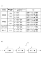
図8(a)は、信号制御部2より受信されるスピーカ制御信号の種類(警報種目)と、車両に対する警報対象の方向(警報対象の方向)と、出力を行うスピーカとその報知信号との組み合わせ(スピーカと報知信号との組み合わせ)と、その報知処理における説明(内容)とを示した表である。 FIG. 8A shows the types of speaker control signals received from the signal control unit 2 (alarm type), the direction of the alarm target with respect to the vehicle (the direction of the alarm target) , the speaker that performs output, and the notification signal thereof. It is the table | surface which showed the combination (combination of a speaker and an alerting signal) and the description (contents) in the alerting | reporting process.
さらに、上述したような車線逸脱に関する報知を行う場合には、座面部21および背もたれ部22の左側に設置されるスピーカEX1およびEX3に対してのみ、上述した時間差、周波数変化、さらにオーバーラップ処理による振動および音の出力処理が行われる。このため、運転者は、振動・音の出力が行われるスピーカの位置およびその組み合わせによって、どのような警報に対する報知が行われたのかを感覚的に判断することができると共に、注意を払うべき方向を判断することが可能となる。 Furthermore, when performing notification relating to vehicle lines departing as described above, only the speaker EX1 and EX3 are installed on the left side of the seat surface portion 21 and the backrest portion 22, the time difference described above, the frequency change, further overlap processing Vibration and sound output processing is performed. For this reason, the driver can sensuously determine what kind of alarm has been notified by the position of the speaker where vibration and sound are output and the combination thereof, and the direction in which attention should be paid Can be determined.
[車両接近報知(前方車両)の場合]
また、信号制御部2が、警報信号出力部100より車両接近に関する警報信号を受信した場合であって、車両が前方から接近する場合に、信号制御部2は、出力信号調整部9に対して、「車両接近に対する報知」であって、「前方車両である旨の情報」を、スピーカ制御信号として出力する。出力信号調整部9では、信号制御部2より受信したスピーカ制御信号に基づいて、座面部21の左右前方部分に設置されるスピーカEX1およびEX2に対して、報知信号V1の振動および音を出力する処理を行う。その後、出力信号調整部9は、背もたれ部22の左右上部に設置されるスピーカEX3およびEX4に対して、報知信号V2の振動および音を出力する処理を行う。
[If the car both approach warning (front vehicle)
In addition, when the signal control unit 2 receives an alarm signal related to vehicle approach from the alarm signal output unit 100 and the vehicle approaches from the front, the signal control unit 2 controls the output signal adjustment unit 9. , “Notification of approaching vehicle” and “information indicating that the vehicle is ahead” is output as a speaker control signal. Based on the speaker control signal received from the signal control unit 2, the output signal adjustment unit 9 outputs the vibration and sound of the notification signal V <b> 1 to the speakers EX <b> 1 and EX <b> 2 installed at the left and right front portions of the seat surface unit 21. Process. Thereafter, the output signal adjustment unit 9 performs a process of outputting vibration and sound of the notification signal V2 to the speakers EX3 and EX4 installed on the left and right upper portions of the backrest unit 22.
[車両接近報知(後方車両)の場合]
一方で、信号制御部2が、警報信号出力部100より車両接近に関する警報信号を受信した場合であって、車両が後方から接近する場合に、信号制御部2は、出力信号調整部9に対して、「車両接近に対する報知」であって、「後方車両である旨の情報」を、スピーカ制御信号として出力する。出力信号調整部9では、信号制御部2より受信したスピーカ制御信号に基づいて、背もたれ部22の左右上部に設置されるスピーカEX3およびEX4に対して、報知信号V1の振動および音を出力する処理を行う。その後、出力信号調整部9は、座面部21の左右前方部分に設置されるスピーカEX1およびEX2に対して、報知信号V2の振動および音を出力する処理を行う。
[In the case of car both approach warning (rear vehicle)]
On the other hand, when the signal control unit 2 receives an alarm signal related to vehicle approach from the alarm signal output unit 100 and the vehicle approaches from behind, the signal control unit 2 controls the output signal adjustment unit 9. Thus, “notification of approaching vehicle” and “information indicating that the vehicle is behind” is output as a speaker control signal. In the output signal adjustment unit 9, based on the speaker control signal received from the signal control unit 2, a process for outputting vibration and sound of the notification signal V <b> 1 to the speakers EX <b> 3 and EX <b> 4 installed on the left and right upper portions of the backrest unit 22. I do. Thereafter, the output signal adjustment unit 9 performs a process of outputting vibration and sound of the notification signal V2 to the speakers EX1 and EX2 installed in the left and right front portions of the seat surface portion 21.
また、車両用警報装置1では、座面部21及び背もたれ部22に設けられるスピーカ(エキサイタ)EX1〜EX4において、車線逸脱報知、車両接近報知、居眠り報知、急カーブ報知等を、時間分割および周波数分割されたスイープ信号により、振動として出力させることができると共に、周波数変換処理された中域の音信号により、音として出力させることができる。このため、運転者に対して効果的な報知を行うことが可能になると共に、方向性のある情報を報知することが可能となり、運転者に対する警報の認知向上を図ることが可能になる。 Further, in the vehicle alarm apparatus 1, the speaker (exciter) EX1~EX4 provided on the seat surface portion 21 and the backrest portion 22, the car line deviation notification, vehicle approach warning, snooze notification, Sharp notification, etc., time division and frequency The divided sweep signal can be output as vibration, and can be output as sound by the mid-range sound signal subjected to frequency conversion processing. For this reason, it becomes possible to perform effective notification to the driver, to notify directional information, and to improve recognition of an alarm for the driver.
Claims (2)
該エキサイタで信号を振動として出力させることが可能な周波数帯域内において、一定の速度で所定波の周波数を変化させることにより、前記振動の周波数を連続的に変化させることが可能なスイープ信号を生成するスイープ信号生成手段と、
前記スイープ信号において一定の速度で変化される周波数帯域内の一部の帯域をオーバーラップ周波数帯域とし、該オーバーラップ周波数帯域を含み当該オーバーラップ周波数帯域の周波数以上となる高域寄りの周波数帯域内で前記所定波の周波数を変化させることにより、前記振動の周波数を連続的に変化させる高域スイープ信号と、前記オーバーラップ周波数帯域を含み当該オーバーラップ周波数帯域の周波数以下となる低域寄りの周波数帯域内で前記所定波の周波数を変化させることにより、前記振動の周波数を連続的に変化させる低域スイープ信号とに、前記スイープ信号を分割するスイープ信号分割手段と、
前記高域スイープ信号および前記低域スイープ信号のうち少なくとも一方の信号を、複数の前記エキサイタのうちのいずれかのエキサイタより出力させ、前記高域スイープ信号および前記低域スイープ信号のうち少なくとも他方の信号を、複数の前記エキサイタのうちのいずれか他のエキサイタより出力させることを決定する信号出力決定手段と、
該信号出力決定手段の前記決定に基づいて、前記高域スイープ信号および前記低域スイープ信号を、決定された前記いずれかのエキサイタより出力させるための調整を行う信号出力調整手段と
を備えることを特徴とする報知装置。 A plurality of exciters which are cushion material portions of the seat and are installed at different positions of the seat;
A sweep signal capable of continuously changing the frequency of the vibration is generated by changing the frequency of a predetermined wave at a constant speed within a frequency band in which the exciter can output a signal as vibration. Sweep signal generating means for performing,
In the sweep signal, a part of the frequency band that is changed at a constant speed is defined as an overlap frequency band, and the frequency band is close to a high frequency band that includes the overlap frequency band and is equal to or higher than the frequency of the overlap frequency band. A high-frequency sweep signal that continuously changes the frequency of the vibration by changing the frequency of the predetermined wave, and a frequency near the low frequency that includes the overlap frequency band and is equal to or less than the frequency of the overlap frequency band A sweep signal dividing unit that divides the sweep signal into a low-frequency sweep signal that continuously changes the frequency of the vibration by changing the frequency of the predetermined wave within a band;
At least one of the high-frequency sweep signal and the low-frequency sweep signal is output from one of the exciters, and at least the other of the high-frequency sweep signal and the low-frequency sweep signal is output. A signal output determining means for determining that a signal is output from any other exciter among the plurality of exciters;
Signal output adjusting means for performing adjustment to output the high-frequency sweep signal and the low-frequency sweep signal from any of the determined exciters based on the determination of the signal output determining means. A characteristic notification device.
前記スイープ信号において一定の速度で変化される周波数帯域内の一部の帯域をオーバーラップ周波数帯域とし、スイープ信号分割手段が、該オーバーラップ周波数帯域を含み当該オーバーラップ周波数帯域の周波数以上となる高域寄りの周波数帯域内で前記所定波の周波数を変化させることにより、前記振動の周波数を連続的に変化させる高域スイープ信号と、前記オーバーラップ周波数帯域を含み当該オーバーラップ周波数帯域の周波数以下となる低域寄りの周波数帯域内で前記所定波の周波数を変化させることにより、前記振動の周波数を連続的に変化させる低域スイープ信号とに、前記スイープ信号を分割するスイープ信号分割ステップと、
信号出力決定手段が、前記高域スイープ信号および前記低域スイープ信号のうち少なくとも一方の信号を、複数の前記エキサイタのうちのいずれかのエキサイタより出力させ、前記高域スイープ信号および前記低域スイープ信号のうち少なくとも他方の信号を、複数の前記エキサイタのうちのいずれか他のエキサイタより出力させることを決定する信号出力決定ステップと、
該信号出力決定ステップによる前記決定に基づいて、信号出力調整手段が、前記高域スイープ信号および前記低域スイープ信号を、決定された前記いずれかのエキサイタより出力させるための調整を行う信号出力調整ステップと
を備えることを特徴とする報知装置の報知方法。 Sweep signal generation by changing the frequency of a predetermined wave at a constant speed within a frequency band where multiple exciters installed at different positions in the cushion material part of the seat can output signals as vibrations A means for generating a sweep signal capable of continuously changing a frequency of the vibration;
A part of the frequency band that changes at a constant speed in the sweep signal is defined as an overlap frequency band, and the sweep signal dividing means includes the overlap frequency band and has a frequency that is equal to or higher than the frequency of the overlap frequency band. A high-frequency sweep signal that continuously changes the frequency of the vibration by changing the frequency of the predetermined wave within a frequency band closer to the band, and the frequency of the overlap frequency band that is equal to or lower than the frequency of the overlap frequency band A sweep signal dividing step for dividing the sweep signal into a low-frequency sweep signal that continuously changes the frequency of the vibration by changing the frequency of the predetermined wave within a frequency band closer to the low frequency range,
The signal output determining means outputs at least one of the high-frequency sweep signal and the low-frequency sweep signal from any one of the exciters, and the high-frequency sweep signal and the low-frequency sweep A signal output determining step for determining that at least the other of the signals is output from any other exciter of the plurality of exciters;
Based on the determination in the signal output determination step, the signal output adjustment means performs adjustment for outputting the high-frequency sweep signal and the low-frequency sweep signal from any of the determined exciters. An informing method for an informing device comprising the steps of:
Priority Applications (5)
| Application Number | Priority Date | Filing Date | Title |
|---|---|---|---|
| JP2015137013A JP6511355B2 (en) | 2015-07-08 | 2015-07-08 | Informing apparatus and informing method |
| EP16821271.0A EP3310071B1 (en) | 2015-07-08 | 2016-06-28 | Notification device and notification method |
| US15/736,760 US10046773B2 (en) | 2015-07-08 | 2016-06-28 | Notification device and notification method |
| CN201680036003.8A CN107683609B (en) | 2015-07-08 | 2016-06-28 | Notify device and notification method |
| PCT/JP2016/069087 WO2017006802A1 (en) | 2015-07-08 | 2016-06-28 | Notification device and notification method |
Applications Claiming Priority (1)
| Application Number | Priority Date | Filing Date | Title |
|---|---|---|---|
| JP2015137013A JP6511355B2 (en) | 2015-07-08 | 2015-07-08 | Informing apparatus and informing method |
Publications (3)
| Publication Number | Publication Date |
|---|---|
| JP2017021476A JP2017021476A (en) | 2017-01-26 |
| JP2017021476A5 true JP2017021476A5 (en) | 2018-06-28 |
| JP6511355B2 JP6511355B2 (en) | 2019-05-15 |
Family
ID=57685495
Family Applications (1)
| Application Number | Title | Priority Date | Filing Date |
|---|---|---|---|
| JP2015137013A Active JP6511355B2 (en) | 2015-07-08 | 2015-07-08 | Informing apparatus and informing method |
Country Status (5)
| Country | Link |
|---|---|
| US (1) | US10046773B2 (en) |
| EP (1) | EP3310071B1 (en) |
| JP (1) | JP6511355B2 (en) |
| CN (1) | CN107683609B (en) |
| WO (1) | WO2017006802A1 (en) |
Families Citing this family (15)
| Publication number | Priority date | Publication date | Assignee | Title |
|---|---|---|---|---|
| JP6576225B2 (en) * | 2015-11-27 | 2019-09-18 | クラリオン株式会社 | Vehicle notification device and vehicle notification method |
| JP6511486B2 (en) * | 2017-05-30 | 2019-05-15 | クラリオン株式会社 | Vibration generating device and vibration generating method |
| JP6576402B2 (en) * | 2017-08-04 | 2019-09-18 | クラリオン株式会社 | Vehicle alarm device and vehicle alarm method |
| JP6954069B2 (en) * | 2017-12-08 | 2021-10-27 | トヨタ自動車株式会社 | Vehicle alert device |
| JP7176187B2 (en) * | 2017-12-11 | 2022-11-22 | 日産自動車株式会社 | Driving support method and driving support device |
| CN108325806B (en) * | 2017-12-29 | 2020-08-21 | 瑞声科技(新加坡)有限公司 | Vibration signal generation method and device |
| US10406976B2 (en) * | 2018-01-31 | 2019-09-10 | Ford Global Technologies, Llc | Multi-purpose automotive sound device |
| CN108769871B (en) * | 2018-05-17 | 2021-07-13 | Oppo广东移动通信有限公司 | Sound production method, sound production device, electronic device and storage medium |
| US10748391B2 (en) * | 2018-12-27 | 2020-08-18 | Immersion Corporation | Haptic signal conversion system |
| US11760371B2 (en) * | 2019-03-15 | 2023-09-19 | Honda Motor Co., Ltd | Vehicle communication device and non-transitory computer-readable recording medium storing program |
| JP2020187410A (en) * | 2019-05-10 | 2020-11-19 | 株式会社東海理化電機製作所 | Attention calling device |
| US20220207970A1 (en) * | 2019-05-17 | 2022-06-30 | Kabushiki Kaisha Tokai Rika Denki Seisakusho | Control system and presentation system |
| JP7262314B2 (en) * | 2019-06-05 | 2023-04-21 | フォルシアクラリオン・エレクトロニクス株式会社 | Vibration output device and program for vibration output |
| US11030863B2 (en) * | 2019-10-02 | 2021-06-08 | Toyota Motor Engineering & Manufacturing North America, Inc. | Systems and methods for providing audio information in a vehicle |
| JP2022119496A (en) * | 2021-02-04 | 2022-08-17 | 本田技研工業株式会社 | Seat belt device for vehicle |
Family Cites Families (26)
| Publication number | Priority date | Publication date | Assignee | Title |
|---|---|---|---|---|
| US6760451B1 (en) * | 1993-08-03 | 2004-07-06 | Peter Graham Craven | Compensating filters |
| WO2002002368A1 (en) * | 2000-07-03 | 2002-01-10 | Med-Dev Limited | Method and apparatus for determining the presence and/or absence and/or a characteristic of an object on a support |
| US7375728B2 (en) * | 2001-10-01 | 2008-05-20 | University Of Minnesota | Virtual mirror |
| US20050149251A1 (en) * | 2000-07-18 | 2005-07-07 | University Of Minnesota | Real time high accuracy geospatial database for onboard intelligent vehicle applications |
| US7245891B2 (en) * | 2003-10-21 | 2007-07-17 | Kyocera Wireless Corp. | Wireless mobile communication device having a speaker vibration alert and method of using same |
| US7681949B2 (en) * | 2006-04-12 | 2010-03-23 | Lear Corporation | Haptic vehicle seat |
| JP2008077631A (en) * | 2006-08-24 | 2008-04-03 | Toyota Central R&D Labs Inc | Seat, vehicle seat, and information presentation device for vehicle |
| JP4826441B2 (en) | 2006-11-17 | 2011-11-30 | トヨタ自動車株式会社 | Vehicle warning system |
| JP2008141465A (en) * | 2006-12-01 | 2008-06-19 | Fujitsu Ten Ltd | Sound field reproduction system |
| JP2008141477A (en) * | 2006-12-01 | 2008-06-19 | Fujitsu Ten Ltd | Sensory acoustic system |
| DE102007031677B4 (en) * | 2007-07-06 | 2010-05-20 | Sda Software Design Ahnert Gmbh | Method and apparatus for determining a room acoustic impulse response in the time domain |
| JP2009031946A (en) * | 2007-07-25 | 2009-02-12 | Toyota Central R&D Labs Inc | Information presentation device |
| JP2009039167A (en) * | 2007-08-06 | 2009-02-26 | Toyota Motor Corp | Sleepiness determining device |
| DE102008040113A1 (en) * | 2008-07-03 | 2010-01-07 | Robert Bosch Gmbh | Sensible driver feedback regarding the operational readiness of a vehicle |
| US8339285B2 (en) * | 2009-07-27 | 2012-12-25 | The Boeing Company | Tactile pilot alerting system and method |
| JP5003734B2 (en) | 2009-08-06 | 2012-08-15 | 株式会社日本自動車部品総合研究所 | Information presentation device |
| EP2501583B1 (en) * | 2009-11-18 | 2020-04-29 | Adient Luxembourg Holding S.à r.l. | Haptic feedback system for vehicle seating |
| JP5678894B2 (en) | 2009-12-08 | 2015-03-04 | 日本電気株式会社 | Information presentation device using tactile stimulation by vibrator |
| US8217767B2 (en) * | 2010-06-09 | 2012-07-10 | Denso Corporation | Vehicle presence notification apparatus |
| US8804093B2 (en) * | 2011-10-26 | 2014-08-12 | LeVoy Haight | Systems and methods for theater seat movement |
| DK2780906T3 (en) * | 2011-12-22 | 2017-01-02 | Cirrus Logic Int Semiconductor Ltd | METHOD AND APPARATUS FOR WIND NOISE DETECTION |
| US9421908B2 (en) * | 2012-06-22 | 2016-08-23 | GM Global Technology Operations LLC | Alert systems and methods for a vehicle with improved actuator placement |
| EP2918467A4 (en) * | 2012-11-08 | 2016-06-08 | Toyota Motor Co Ltd | Drive assist device and method, collision prediction device and method, and alerting device and method |
| US10434916B2 (en) * | 2013-12-27 | 2019-10-08 | Ts Tech Co., Ltd. | Seat with wakefulness-maintaining device |
| US9729961B2 (en) * | 2014-11-25 | 2017-08-08 | Bose Corporation | Actively suspended seat with bass loudspeakers |
| WO2016197068A1 (en) * | 2015-06-03 | 2016-12-08 | Levant Power Corporation | Methods and systems for controlling vehicle body motion and occupant experience |
-
2015
- 2015-07-08 JP JP2015137013A patent/JP6511355B2/en active Active
-
2016
- 2016-06-28 EP EP16821271.0A patent/EP3310071B1/en active Active
- 2016-06-28 US US15/736,760 patent/US10046773B2/en active Active
- 2016-06-28 CN CN201680036003.8A patent/CN107683609B/en active Active
- 2016-06-28 WO PCT/JP2016/069087 patent/WO2017006802A1/en active Application Filing
Similar Documents
| Publication | Publication Date | Title |
|---|---|---|
| JP2017021476A5 (en) | ||
| WO2017014035A1 (en) | Automobile proximity warning system | |
| JP5304735B2 (en) | Tracking control device | |
| JP6449195B2 (en) | Driving assistance device | |
| JP6146228B2 (en) | Object detection device and object detection system | |
| JP2008273251A (en) | Vehicular alarm device | |
| JP4823781B2 (en) | Vehicle travel safety device | |
| JP2017134826A (en) | System and method for external sound synthesis of vehicle | |
| JP5794381B2 (en) | Travel control device and travel control method | |
| JP6511355B2 (en) | Informing apparatus and informing method | |
| US9908469B2 (en) | Driving support device | |
| WO2013122030A1 (en) | Travel control device and travel control method | |
| JP6287614B2 (en) | Lane change support device and program | |
| JPWO2014203333A1 (en) | Overtaking support system | |
| CN105799584A (en) | Surrounding vehicle whistling sound microprocessor, prompt device and automatic driving system | |
| JP2019159682A (en) | Driving assistance system | |
| JP6000658B2 (en) | Obstacle avoidance support device and obstacle avoidance support method | |
| DE102015202628A1 (en) | VEHICLE-MOUNTED APPARATUS FOR SELECTING PRECEDING VEHICLE POSITIONED IN THE TRAVEL PATH OF THE HOST VEHICLE OF THE APPARATUS | |
| EP3378706A1 (en) | Vehicular notification device and vehicular notification method | |
| JP2008129734A (en) | Solid sound image warning device | |
| JP2009186277A (en) | Object detection device | |
| JP2019038363A (en) | Vehicular travelling control device | |
| JP2013015969A (en) | Alarm sound generating device and alarm sound generating method | |
| JP2011150578A (en) | Vehicle approach notification device | |
| JP2008226150A (en) | Periphery monitoring device and method |