JP2017017627A - Transmission equipment, transmission method and transmission system - Google Patents

Transmission equipment, transmission method and transmission system Download PDF

Info

Publication number
JP2017017627A
JP2017017627A JP2015134682A JP2015134682A JP2017017627A JP 2017017627 A JP2017017627 A JP 2017017627A JP 2015134682 A JP2015134682 A JP 2015134682A JP 2015134682 A JP2015134682 A JP 2015134682A JP 2017017627 A JP2017017627 A JP 2017017627A
Authority
JP
Japan
Prior art keywords
signal
path
otn
transmission device
line
Prior art date
Legal status (The legal status is an assumption and is not a legal conclusion. Google has not performed a legal analysis and makes no representation as to the accuracy of the status listed.)
Pending
Application number
JP2015134682A
Other languages
Japanese (ja)
Inventor
伸吾 弘中
Shingo Hironaka
伸吾 弘中
本田 崇
Takashi Honda
崇 本田
Current Assignee (The listed assignees may be inaccurate. Google has not performed a legal analysis and makes no representation or warranty as to the accuracy of the list.)
Fujitsu Ltd
Original Assignee
Fujitsu Ltd
Priority date (The priority date is an assumption and is not a legal conclusion. Google has not performed a legal analysis and makes no representation as to the accuracy of the date listed.)
Filing date
Publication date
Application filed by Fujitsu Ltd filed Critical Fujitsu Ltd
Priority to JP2015134682A priority Critical patent/JP2017017627A/en
Priority to US15/187,190 priority patent/US20170005934A1/en
Publication of JP2017017627A publication Critical patent/JP2017017627A/en
Pending legal-status Critical Current

Links

Images

Classifications

    • HELECTRICITY
    • H04ELECTRIC COMMUNICATION TECHNIQUE
    • H04LTRANSMISSION OF DIGITAL INFORMATION, e.g. TELEGRAPHIC COMMUNICATION
    • H04L47/00Traffic control in data switching networks
    • H04L47/10Flow control; Congestion control
    • H04L47/12Avoiding congestion; Recovering from congestion
    • HELECTRICITY
    • H04ELECTRIC COMMUNICATION TECHNIQUE
    • H04BTRANSMISSION
    • H04B10/00Transmission systems employing electromagnetic waves other than radio-waves, e.g. infrared, visible or ultraviolet light, or employing corpuscular radiation, e.g. quantum communication
    • H04B10/27Arrangements for networking
    • HELECTRICITY
    • H04ELECTRIC COMMUNICATION TECHNIQUE
    • H04LTRANSMISSION OF DIGITAL INFORMATION, e.g. TELEGRAPHIC COMMUNICATION
    • H04L49/00Packet switching elements
    • H04L49/50Overload detection or protection within a single switching element
    • HELECTRICITY
    • H04ELECTRIC COMMUNICATION TECHNIQUE
    • H04LTRANSMISSION OF DIGITAL INFORMATION, e.g. TELEGRAPHIC COMMUNICATION
    • H04L49/00Packet switching elements
    • H04L49/50Overload detection or protection within a single switching element
    • H04L49/505Corrective measures

Abstract

PROBLEM TO BE SOLVED: To provide transmission equipment etc. capable of automatically setting a second line to transfer a first signal.SOLUTION: The transmission equipment includes a plurality of first communication units, a second communication unit, a determination unit and a setting unit. Each first communication unit is connected to a first line which transmits a first signal. The second communication unit is connected to a second line which transmits a second signal enabling the insertion of the first signal. The determination unit determines whether or not a data amount of the first signal exceeds a predetermined threshold at each first communication unit. The setting unit sets to the second communication unit a second line which transfers the first signal, on the basis of destination information in the first signal, when the data amount of the first signal exceeds the predetermined threshold.SELECTED DRAWING: Figure 3

Description

本発明は、伝送装置、伝送方法及び伝送システムに関する。   The present invention relates to a transmission device, a transmission method, and a transmission system.

IEEE(Institute of Electrical and Electronic Engineers)及びITU−T(International Telecommunication Union−Telecommunication)G.709規格に示されるOTN(Optical Transport Network)伝送方式が標準化されている。OTNは、光ネットワーク(NW:Network)へ流入するクライアント信号をOTU(Optical channel Transport Unit)に格納して伝送する方式である。OTNは、WDM(Wavelength Division Multiplexing)技術を適用した光NWにおいて、種類の異なるクライアント信号をトランスペアレントに伝送できる技術である。   The OTN (Optical Transport Network) transmission system shown in IEEE (Institute of Electrical and Electronic Engineers) and ITU-T (International Telecommunication Union-Telecommunication) G.709 standard is standardized. OTN is a system in which a client signal flowing into an optical network (NW: Network) is stored in an OTU (Optical channel Transport Unit) and transmitted. OTN is a technology that can transparently transmit different types of client signals in an optical NW to which WDM (Wavelength Division Multiplexing) technology is applied.

近年、CAPEX(設備投資)とOPEX(運用コスト)を抑えるため、WDM(Layer 0)、OTN(Layer 1)やパケット(Layer 2)をサポートするマルチレイヤの伝送装置が開発されている。伝送装置は、受信パケットをビット当たりの伝送単価が低いOTNパス経由で宛先に転送することも可能である。   In recent years, multi-layer transmission apparatuses that support WDM (Layer 0), OTN (Layer 1), and packets (Layer 2) have been developed to reduce CAPEX (capital investment) and OPEX (operation cost). The transmission apparatus can also transfer the received packet to the destination via an OTN path having a low transmission unit cost per bit.

パケットNWでは、各伝送装置が宛先MACアドレス毎に転送先を管理するMACテーブルを生成し、MACテーブルを参照して、宛先MACアドレスに応じた転送先にパケットを転送する。また、OTNNWでは、管理装置でNW内の各伝送装置を集中管理し、管理者の設定でOTNパスを設定し、その設定したOTNパスでOTNフレームを伝送する。   In the packet NW, each transmission device generates a MAC table for managing a transfer destination for each destination MAC address, and refers to the MAC table to transfer the packet to a transfer destination corresponding to the destination MAC address. Further, in the OTNNNW, each transmission apparatus in the NW is centrally managed by the management apparatus, an OTN path is set by an administrator setting, and an OTN frame is transmitted through the set OTN path.

特開2013−106153号公報JP 2013-106153 A

パケットNWとOTNNWとを同一トポロジのNWで構築した伝送システム内の各伝送装置では、受信パケットをパケットパスではなく、OTNパスで伝送することも可能になる。しかしながら、OTNパスを自動設定するのは困難である。しかも、伝送システム内の伝送装置の数が増加するに連れて、その処理負荷が大きくなる。   In each transmission apparatus in the transmission system in which the packet NW and the OTNNNW are constructed with the NW having the same topology, it is possible to transmit the received packet not on the packet path but on the OTN path. However, it is difficult to automatically set the OTN path. Moreover, the processing load increases as the number of transmission devices in the transmission system increases.

一つの側面では、パケットを転送するためのOTNパスを自動設定できる伝送装置、伝送方法及び伝送システムを提供することを目的とする。   An object of one aspect is to provide a transmission apparatus, a transmission method, and a transmission system capable of automatically setting an OTN path for transferring a packet.

一つの案の伝送装置は、複数の第1の通信部と、第2の通信部と、判定部と、設定部とを有する。第1の通信部は、第1の信号を伝送する第1の回線と接続する。第2の通信部は、第1の信号を挿入可能にする第2の信号を伝送する第2の回線と接続する。判定部は、第1の通信部にて前記第1の信号のデータ量が所定閾値を超えたか否かを判定する。設定部は、第1の信号のデータ量が所定閾値を超えた場合に、第1の信号内の宛先情報に基づき、第2の通信部にて、第1の信号を転送する第2の回線を設定する。   One proposed transmission apparatus includes a plurality of first communication units, a second communication unit, a determination unit, and a setting unit. The first communication unit is connected to a first line that transmits the first signal. The second communication unit is connected to a second line that transmits a second signal enabling insertion of the first signal. The determination unit determines whether the data amount of the first signal exceeds a predetermined threshold value in the first communication unit. The setting unit uses the second communication unit to transfer the first signal based on the destination information in the first signal when the data amount of the first signal exceeds a predetermined threshold. Set.

第1の信号を転送するための第2の回線を自動設定できる。   The second line for transferring the first signal can be automatically set.

図1は、本実施例の伝送システムの一例を示す説明図である。FIG. 1 is an explanatory diagram illustrating an example of a transmission system according to the present embodiment. 図2は、伝送装置のハードウェア構成の一例を示すブロック図である。FIG. 2 is a block diagram illustrating an example of a hardware configuration of the transmission apparatus. 図3は、伝送装置の機能構成の一例を示す説明図である。FIG. 3 is an explanatory diagram illustrating an example of a functional configuration of the transmission apparatus. 図4は、MACテーブルの一例を示す説明図である。FIG. 4 is an explanatory diagram showing an example of the MAC table. 図5は、変換テーブルの一例を示す説明図である。FIG. 5 is an explanatory diagram showing an example of the conversion table. 図6は、OTNフレームのフォーマット構成の一例を示す説明図である。FIG. 6 is an explanatory diagram showing an example of the format configuration of the OTN frame. 図7は、パケットNWの受信パケットをOTNパスで転送する際の動作の一例を示す説明図である。FIG. 7 is an explanatory diagram showing an example of the operation when the received packet of the packet NW is transferred through the OTN path. 図8は、パス確認処理に関わる各伝送装置の処理動作の一例を示すシーケンスである。FIG. 8 is a sequence illustrating an example of a processing operation of each transmission apparatus related to the path confirmation process. 図9は、パス設定処理に関わる各伝送装置の処理動作の一例を示すシーケンスである。FIG. 9 is a sequence illustrating an example of a processing operation of each transmission apparatus related to the path setting process. 図10は、パス削除処理に関わる各伝送装置の処理動作の一例を示すシーケンスである。FIG. 10 is a sequence illustrating an example of a processing operation of each transmission apparatus related to the path deletion process. 図11は、始点側設定処理に関わる伝送装置の処理動作の一例を示すフローチャートである。FIG. 11 is a flowchart illustrating an example of a processing operation of the transmission apparatus related to the start point side setting process. 図12は、始点側転送処理に関わる伝送装置の処理動作の一例を示すフローチャートである。FIG. 12 is a flowchart illustrating an example of the processing operation of the transmission apparatus related to the start point side transfer process. 図13は、中継点側設定処理に関わる伝送装置の処理動作の一例を示すフローチャートである。FIG. 13 is a flowchart illustrating an example of the processing operation of the transmission apparatus related to the relay point side setting process. 図14は、終点側設定処理に関わる伝送装置の処理動作の一例を示すフローチャートである。FIG. 14 is a flowchart illustrating an example of processing operation of the transmission apparatus related to the end point setting process.

以下、図面に基づいて、本願の開示する伝送装置、伝送方法及び伝送システムの実施例を詳細に説明する。尚、本実施例により、開示技術が限定されるものではない。また、以下に示す各実施例は、矛盾を起こさない範囲で適宜組み合わせても良い。   Hereinafter, embodiments of a transmission device, a transmission method, and a transmission system disclosed in the present application will be described in detail based on the drawings. The disclosed technology is not limited by the present embodiment. Moreover, you may combine suitably each Example shown below in the range which does not cause contradiction.

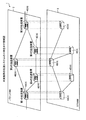
図1は、本実施例の伝送システム1の一例を示す説明図である。図1に示す伝送システム1は、パケットを格納したフレームを伝送するパケットNW2と、OTNフレームを伝送するOTNNW3とを有し、パケットNW2とOTNNW3とを同一トポロジのNWで構築したシステムである。パケットNW2は、第1の信号であるフレームを伝送する第1の回線であるパケットパスで接続して構成するL2(Layer 2)のNWである。OTNNW3は、パケットを挿入可能にする第2の信号であるOTNフレームを伝送する第2の回線であるOTNパスで接続して構成するL1(Layer 1)のNWである。   FIG. 1 is an explanatory diagram illustrating an example of a transmission system 1 according to the present embodiment. A transmission system 1 shown in FIG. 1 has a packet NW2 for transmitting a frame storing a packet and an OTNNW3 for transmitting an OTN frame, and the packet NW2 and the OTNNW3 are constructed by NWs having the same topology. The packet NW2 is an L2 (Layer 2) NW configured by connecting through a packet path that is a first line for transmitting a frame that is a first signal. The OTNNW 3 is an L1 (Layer 1) NW configured by connecting with an OTN path that is a second line for transmitting an OTN frame that is a second signal enabling insertion of a packet.

伝送システム1は、パケットNW2及びOTNNW3を光ファイバ5で接続する複数の伝送装置4、例えば、第1の伝送装置4A、第2の伝送装置4B、第3の伝送装置4C、第4の伝送装置4D及び第5の伝送装置4Eの5台の伝送装置4を有する。   The transmission system 1 includes a plurality of transmission apparatuses 4 that connect the packets NW2 and OTNNW3 with optical fibers 5, for example, a first transmission apparatus 4A, a second transmission apparatus 4B, a third transmission apparatus 4C, and a fourth transmission apparatus. It has five transmission devices 4 of 4D and fifth transmission device 4E.

図2は、伝送装置4のハードウェア構成の一例を示すブロック図である。尚、説明の便宜上、伝送装置4として説明するが、第1〜第5の伝送装置4A〜4Eは同一の構成であるため、同一の構成には同一符号を付すことで、その重複する構成及び動作の説明については省略する。   FIG. 2 is a block diagram illustrating an example of a hardware configuration of the transmission device 4. For convenience of explanation, the transmission device 4 is described. However, since the first to fifth transmission devices 4A to 4E have the same configuration, the same configuration is denoted by the same reference numeral, and the overlapping configuration and The explanation of the operation is omitted.

図2に示す伝送装置4は、複数枚のパケットカード11と、複数枚のOTNカード12と、SW(Switch)カード13と、CPU(Central Processing Unit)カード14とを有する。パケットカード11は、パケットNW2との通信インタフェースを実装したカードである。尚、説明の便宜上、パケットカード11は、例えば、第1のパケットカード11A及び第2のパケットカード11Bの2枚である。OTNカード12は、OTNNW3との通信インタフェースを実装したカードである。尚、説明の便宜上、OTNカード12は、例えば、第1のOTNカード12A及び第2のOTNカード12Bの2枚である。   The transmission apparatus 4 shown in FIG. 2 includes a plurality of packet cards 11, a plurality of OTN cards 12, a SW (Switch) card 13, and a CPU (Central Processing Unit) card 14. The packet card 11 is a card on which a communication interface with the packet NW2 is mounted. For convenience of explanation, there are two packet cards 11, for example, a first packet card 11A and a second packet card 11B. The OTN card 12 is a card on which a communication interface with the OTNNN3 is mounted. For convenience of explanation, there are two OTN cards 12, for example, a first OTN card 12A and a second OTN card 12B.

SWカード13は、パケットカード11同士、OTNカード12同士若しくは、パケットカード11とOTNカード12との間を切替接続するスイッチを実装したカードである。SWカード13は、第1のパケットカード11Aと第2のパケットカード11Bとの間を接続し、パケットNW2内のパケットパスでフレームを伝送する。SWカード13は、第1のOTNカード12Aと第2のOTNカード12Bとの間を接続し、OTNNW3内のOTNパスでOTNフレームを伝送する。また、SWカード13は、例えば、第1のパケットカード11Aと第2のOTNカード12Bとの間、又は第2のパケットカード11Bと第1のOTNカード12Aとの間を切替接続する。CPUカード14は、伝送装置4全体を制御するCPUを実装したカードである。   The SW card 13 is a card equipped with a switch for switching connection between the packet cards 11, between the OTN cards 12, or between the packet card 11 and the OTN card 12. The SW card 13 connects the first packet card 11A and the second packet card 11B, and transmits a frame through the packet path in the packet NW2. The SW card 13 connects the first OTN card 12A and the second OTN card 12B, and transmits the OTN frame through the OTN path in the OTNNN3. The SW card 13 switches and connects, for example, between the first packet card 11A and the second OTN card 12B or between the second packet card 11B and the first OTN card 12A. The CPU card 14 is a card on which a CPU that controls the entire transmission device 4 is mounted.

伝送装置4は、スロット番号#1のスロット内に第1のパケットカード11A、スロット番号#2のスロット内に第1のOTNカード12Aを装着している。更に、伝送装置4は、スロット番号#3のスロット内に第2のパケットカード11B、スロット番号#4のスロット内に第2のOTNカード12Bを装着している。   In the transmission apparatus 4, the first packet card 11A is installed in the slot of slot number # 1, and the first OTN card 12A is installed in the slot of slot number # 2. Further, the transmission apparatus 4 has the second packet card 11B installed in the slot of slot number # 3 and the second OTN card 12B installed in the slot of slot number # 4.

図3は、伝送装置4の機能構成の一例を示す説明図である。図3に示すパケットカード11は、パケット通信部21と、パケット処理部22とを有する。パケット通信部21は、パケットNW2と接続してパケット通信を実行する通信部である。パケット処理部22は、各種パケット通信に関わるパケット処理を実行する処理部である。OTNカード12は、OTN通信部31と、OTN処理部32とを有する。OTN通信部31は、OTNNW3と接続してOTN通信を実行する通信部である。OTN処理部32は、各種OTN通信に関わるフレーム処理を実行する処理部である。SWカード13は、マトリックススイッチ13Aを有する。マトリックススイッチ13Aは、パケット処理部22同士、OTN処理部32同士、パケット処理部22とOTN処理部32との間を切替接続するスイッチである。   FIG. 3 is an explanatory diagram illustrating an example of a functional configuration of the transmission device 4. The packet card 11 illustrated in FIG. 3 includes a packet communication unit 21 and a packet processing unit 22. The packet communication unit 21 is a communication unit that performs packet communication by connecting to the packet NW2. The packet processing unit 22 is a processing unit that executes packet processing related to various packet communications. The OTN card 12 includes an OTN communication unit 31 and an OTN processing unit 32. The OTN communication unit 31 is a communication unit that connects to the OTNNW 3 and executes OTN communication. The OTN processing unit 32 is a processing unit that executes frame processing related to various OTN communications. The SW card 13 has a matrix switch 13A. The matrix switch 13 </ b> A is a switch that switches between the packet processing units 22, the OTN processing units 32, and the packet processing unit 22 and the OTN processing unit 32.

CPUカード14は、流量モニタ部41と、OTNモニタ部42と、記憶部43と、制御部44とを有する。流量モニタ部41は、パケットカード11内のパケット通信部21と接続し、受信フレーム内の宛先MACアドレス毎のパケットの流量、すなわちデータ量を測定する。OTNモニタ部42は、OTN通信部31を通じてOTNパスの空き容量をモニタする。記憶部43は、MACテーブル43Aと、変換テーブル43Bと、設定テーブル43Cとを有する。   The CPU card 14 includes a flow rate monitor unit 41, an OTN monitor unit 42, a storage unit 43, and a control unit 44. The flow rate monitor unit 41 is connected to the packet communication unit 21 in the packet card 11 and measures the packet flow rate for each destination MAC address in the received frame, that is, the data amount. The OTN monitor unit 42 monitors the free space of the OTN path through the OTN communication unit 31. The storage unit 43 includes a MAC table 43A, a conversion table 43B, and a setting table 43C.

図4は、MACテーブル43Aの一例を示す説明図である。図4に示すMACテーブル43Aは、パケットの宛先MACアドレス毎に転送先のパケットカード11を識別する識別情報を管理している。尚、識別情報は、例えば、パケットカード11を装着するスロットのスロット番号及びポート番号を有する。制御部44は、受信パケット内の宛先MACアドレスを抽出した場合、MACテーブル43Aを参照し、抽出した宛先MACアドレスに対応する、当該パケットを転送すべき転送先のパケットカード11のスロット番号及びポート番号を認識する。   FIG. 4 is an explanatory diagram showing an example of the MAC table 43A. The MAC table 43A shown in FIG. 4 manages identification information for identifying the transfer destination packet card 11 for each destination MAC address of the packet. The identification information includes, for example, the slot number and port number of the slot in which the packet card 11 is installed. When the control unit 44 extracts the destination MAC address in the received packet, the control unit 44 refers to the MAC table 43A, and corresponds to the extracted destination MAC address and the slot number and port of the transfer destination packet card 11 to which the packet is to be transferred. Recognize the number.

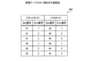
図5は、変換テーブル43Bの一例を示す説明図である。図5に示す変換テーブル43Bは、抽出した転送先のパケットカード11を転送先のOTNカード12に変換するテーブルである。変換テーブル43Bは、受信パケットの転送先のパケットカード11のスロット番号及びポート番号と、転送先のOTNカード12のスロット番号及びポート番号とを対応付けて管理している。制御部44は、受信パケットをOTNパスで転送する際、変換テーブル43Bを参照し、受信パケット内の宛先MACアドレスの転送先のパケットカード11に対応したOTNカード12のスロット番号及びポート番号を認識する。設定テーブル43Cは、OTNパスに関わる各種情報を記憶する。尚、各種情報は、例えば、パス確認要求の場合、そのリクエスト番号、ODU種別、送信元MACアドレス、宛先MACアドレス、受信ポート番号等である。   FIG. 5 is an explanatory diagram showing an example of the conversion table 43B. The conversion table 43B shown in FIG. 5 is a table for converting the extracted transfer destination packet card 11 into the transfer destination OTN card 12. The conversion table 43B manages the slot number and port number of the packet card 11 to which the received packet is transferred and the slot number and port number of the transfer destination OTN card 12 in association with each other. When transferring the received packet through the OTN path, the control unit 44 refers to the conversion table 43B and recognizes the slot number and port number of the OTN card 12 corresponding to the destination packet card 11 of the destination MAC address in the received packet. To do. The setting table 43C stores various information related to the OTN path. The various information includes, for example, a request number, an ODU type, a source MAC address, a destination MAC address, and a reception port number in the case of a path confirmation request.

制御部44は、CPUカード14全体を制御する。制御部44は、第1の判定部51と、第2の判定部52と、設定部53とを有する。第1の判定部51は、流量モニタ部41にて測定した受信パケットの流量が所定閾値を超えたか否かを判定する。第2の判定部52は、受信パケットの流量が所定閾値を超えた場合に、受信パケットの流量が設定可能なOTNパスの空き容量未満であるか否かを判定する。設定部53は、MACテーブル43Aを参照し、受信パケットの宛先MACアドレスに対応する転送先のパケットカード11を抽出する。更に、設定部53は、受信パケットの流量が設定可能なOTNパスの空き容量未満の場合、変換テーブル43Bを参照し、転送先のパケットカード11に対応する転送先のOTNカード12を抽出する。そして、設定部53は、抽出した転送先のOTNカード12を通じて、転送先のOTNパスを設定する。   The control unit 44 controls the entire CPU card 14. The control unit 44 includes a first determination unit 51, a second determination unit 52, and a setting unit 53. The first determination unit 51 determines whether or not the flow rate of the received packet measured by the flow rate monitor unit 41 exceeds a predetermined threshold value. When the flow rate of the received packet exceeds a predetermined threshold, the second determination unit 52 determines whether the flow rate of the received packet is less than a configurable OTN path free capacity. The setting unit 53 refers to the MAC table 43A and extracts the transfer destination packet card 11 corresponding to the destination MAC address of the received packet. Furthermore, when the flow rate of the received packet is less than the free capacity of the settable OTN path, the setting unit 53 refers to the conversion table 43B and extracts the transfer destination OTN card 12 corresponding to the transfer destination packet card 11. Then, the setting unit 53 sets the transfer destination OTN path through the extracted transfer destination OTN card 12.

また、設定部53は、受信パケットの流量が設定可能なOTNパスの空き容量未満でない場合、MACテーブル43Aを参照し、受信パケットの宛先MACアドレスに対応した転送先のパケットカード11を抽出する。そして、設定部53は、抽出した転送先のパケットカード11を通じて、転送先のパケットパスで受信パケットを伝送する。また、設定部53は、受信パケットをOTNパスで転送中に、受信パケットの流量が所定閾値を超えなくなった場合、設定中のOTNパスを削除し、受信パケットを転送先のパケットカード11のパケットパスに切替えて伝送する。   If the flow rate of the received packet is not less than the free capacity of the settable OTN path, the setting unit 53 refers to the MAC table 43A and extracts the transfer destination packet card 11 corresponding to the destination MAC address of the received packet. Then, the setting unit 53 transmits the received packet through the extracted transfer destination packet card 11 through the transfer destination packet path. Also, the setting unit 53 deletes the currently set OTN path and transfers the received packet to the packet of the transfer destination packet card 11 when the flow rate of the received packet does not exceed a predetermined threshold while the received packet is being transferred by the OTN path. Switch to the path and transmit.

図6は、OTNフレームのフォーマット構成の一例を示す説明図である。図6に示すOTNフレーム60は、OH領域61と、ペイロード領域62とを有する。OH領域61は、1列目〜16列目の16バイト×4行のフレームサイズであって、各種OH(Overhead)を格納する領域である。ペイロード領域62は、17列目〜3824列目の3808バイト×4行のフレームサイズであって、各種データを格納する領域である。   FIG. 6 is an explanatory diagram showing an example of the format configuration of the OTN frame. An OTN frame 60 illustrated in FIG. 6 includes an OH area 61 and a payload area 62. The OH area 61 has a frame size of 16 bytes × 4 rows in the first to sixteenth columns and stores various OH (Overhead). The payload area 62 has a frame size of 3808 bytes × 4 rows in the 17th to 3824th columns and stores various data.

OH領域61には、1行目の1列目〜7列目のフレーム同期OH(Frame Alignment OH)と、1行目の8列目〜14列目のOTUOHと、2行目〜4行目の1列目〜14列目のODUOHと、1行目〜4行目の15列目〜16列目のOPUOHとを有する。OTUOHは、OTUのOH領域である。ODUOHは、ODUのOH領域である。OPUOHは、OPUのOH領域である。   In the OH area 61, the first row to the seventh column, frame synchronization OH (Frame Alignment OH), the first row to the eighth column to the 14th column OTUOH, and the second row to the fourth row ODUOH in the 1st to 14th columns and OPUOH in the 15th to 16th columns of the 1st to 4th rows. OTUOH is the OH region of OTU. ODUOH is the OH area of ODU. OPUOH is the OH area of OPU.

フレーム同期OHは、FAS(Frame Alignment Signal)と、MFAS(Multi Frame Alignment Signal)とを有する。FASは、フレーム同期信号である。MFASは、マルチフレームの同期を検出するマルチフレーム同期信号である。OTUOHは、SM(Section Monitoring)と、GCC(General Communication Chanel)0と、RES(Reserved for future international standardization)とを有する。SMは、OTU終端点同士のモニタ状態を示す情報である。GCC0は、OTU終端点同士の通信チャネルをサポートするための情報である。   The frame synchronization OH has FAS (Frame Alignment Signal) and MFAS (Multi Frame Alignment Signal). FAS is a frame synchronization signal. The MFAS is a multi-frame synchronization signal that detects multi-frame synchronization. OTUOH has SM (Section Monitoring), GCC (General Communication Channel) 0, and RES (Reserved for future international standardization). SM is information indicating the monitoring state between the OTU end points. GCC0 is information for supporting a communication channel between OTU termination points.

ODUOHは、RES63と、TCMACT(Tandem Connection Monitoring Activation)と、TCM1〜6と、FTFL(Fault Type & Fault Location reporting channel)と、PM(Path Monitoring)と、EXP(Experimental)とを有する。更に、ODUOHは、GCC1〜2と、APS(Automatic Protection Switching)/PCC(Protection Communication Control channel)とを有する。TCMACTは、タンデムコネクション監視をアクティブ状態にするか否かを識別する情報である。FTFLは、故障タイプ及び故障位置を通知するための情報である。PMは、パス状態を監視した情報である。EXPは、試験用であるか否かを識別する情報である。APS/PCCは、自動予備切替及び切替通信チャネルである。   The ODUOH includes RES 63, TCMMAT (Tandem Connection Monitoring Activation), TCMs 1 to 6, FTFL (Fault Type & Fault Location reporting channel), PM (Path Monitoring), and EXP (Experimental). Furthermore, ODUOH has GCC1-2 and APS (Automatic Protection Switching) / PCC (Protection Communication Control channel). TCMACT is information for identifying whether or not to activate tandem connection monitoring. FTFL is information for notifying a failure type and a failure location. PM is information obtained by monitoring the path state. EXP is information for identifying whether or not it is for testing. APS / PCC is an automatic standby switching and switching communication channel.

ODUOH内のRES63は、リクエスト種別(Request Type)63Aと、リクエスト番号(Request Number)63Bと、RES63Cとを格納するReservation領域である。リクエスト種別63Aは、リクエストの種別を示し、例えば、パス確認要求の場合は“0”、パス確認応答の場合は“1”である。また、リクエスト種別63Aは、パス設定要求の場合は“2”、パス設定応答の場合は“3”、パス削除要求の場合は“4”である。RES63Cは、各種情報を格納可能にし、ODU種別の場合は“0”、送信元MACアドレスの場合は“1”、宛先MACアドレスの場合は“2”、TS番号が1〜64の場合は“3”、TS番号が65〜128の場合は“4”である。   The RES 63 in the ODUOH is a reservation area that stores a request type 63A, a request number 63B, and a RES 63C. The request type 63A indicates the type of request. For example, it is “0” for a path confirmation request and “1” for a path confirmation response. The request type 63A is “2” for a path setting request, “3” for a path setting response, and “4” for a path deletion request. The RES 63C can store various types of information, “0” for the ODU type, “1” for the source MAC address, “2” for the destination MAC address, and “2” for the TS number of 1 to 64. 3 ”and“ 4 ”when the TS number is 65 to 128.

次に本実施例の伝送システム1の動作について説明する。第1の伝送装置4Aは、パケットNW2経由で受信フレームを第3の伝送装置4Cに伝送する際、例えば、第4の伝送装置4D→第5の伝送装置4E→第3の伝送装置4Cの経路のパケットパスで接続する。その結果、第1の伝送装置4Aは、パケットNW2経由で受信フレームを第3の伝送装置4Cに伝送できる。また、第1の伝送装置4Aは、OTNNW3経由でOTNフレームを第3の伝送装置4Cに伝送する際、例えば、第4の伝送装置4D→第5の伝送装置4E→第3の伝送装置4Cの経路のOTNパスで接続する。その結果、第1の伝送装置4Aは、OTNNW3経由でOTNフレームを第3の伝送装置4Cに伝送できる。   Next, the operation of the transmission system 1 of this embodiment will be described. When the first transmission device 4A transmits the received frame to the third transmission device 4C via the packet NW2, for example, the route of the fourth transmission device 4D → the fifth transmission device 4E → the third transmission device 4C. Connect with the packet path. As a result, the first transmission device 4A can transmit the received frame to the third transmission device 4C via the packet NW2. Further, when the first transmission device 4A transmits the OTN frame to the third transmission device 4C via the OTNNN3, for example, the fourth transmission device 4D → the fifth transmission device 4E → the third transmission device 4C. Connect with the OTN path of the route. As a result, the first transmission device 4A can transmit the OTN frame to the third transmission device 4C via the OTNNNW3.

次に、図7は、パケットNW2の受信パケットをOTNパスで転送する際の動作の一例を示す説明図である。第1の伝送装置4Aは、受信パケットの流量が所定閾値を超え、かつ、受信パケットの流量が設定可能なOTNパスの空き容量未満の場合、受信パケット内の宛先MACアドレスの転送先のパケットカード11に対応するOTNカード12があるか否かを判定する。そして、第1の伝送装置4Aは、転送先のOTNカード12がある場合、そのOTNカード12を通じて受信パケットの宛先である第3の伝送装置4CまでのOTNパスの設定を要求すべく、第4の伝送装置4Dに対して受信パケット内の宛先MACアドレスを挿入したパス設定を要求する。   Next, FIG. 7 is an explanatory diagram showing an example of the operation when the received packet of the packet NW2 is transferred through the OTN path. When the flow rate of the received packet exceeds a predetermined threshold and the flow rate of the received packet is less than the free capacity of the settable OTN path, the first transmission device 4A transfers the packet card to which the destination MAC address in the received packet is transferred 11 is determined whether there is an OTN card 12 corresponding to 11. Then, when there is a transfer destination OTN card 12, the first transmission device 4A uses the OTN card 12 to request the setting of the OTN path to the third transmission device 4C that is the destination of the received packet. The transmission apparatus 4D is requested to set a path by inserting the destination MAC address in the received packet.

第4の伝送装置4Dは、第1の伝送装置4Aからのパス設定の要求を受信した場合、設定要求内の宛先MACアドレスの転送先のパケットカード11に対応するOTNカード12があるか否かを判定する。そして、第4の伝送装置4Dは、転送先のOTNカード12がある場合、そのOTNカード12を通じて、第5の伝送装置4Eに対して受信パケット内の宛先MACアドレスを挿入したパス設定を要求する。   When the fourth transmission device 4D receives the path setting request from the first transmission device 4A, whether or not there is an OTN card 12 corresponding to the packet card 11 that is the transfer destination of the destination MAC address in the setting request. Determine. Then, when there is the transfer destination OTN card 12, the fourth transmission device 4D requests the fifth transmission device 4E to set the path by inserting the destination MAC address in the received packet through the OTN card 12. .

第5の伝送装置4Eは、第4の伝送装置4Dからのパス設定の要求を受信した場合、設定要求内の宛先MACアドレスの転送先のパケットカード11に対応するOTNカード12があるか否かを判定する。しかし、第5の伝送装置4Eは、転送先のOTNカード12がない場合、宛先MACアドレスの転送先のパケットカード11を通じて第3の伝送装置4Cとの間のパケットパスで接続する。   When the fifth transmission device 4E receives the path setting request from the fourth transmission device 4D, whether or not there is an OTN card 12 corresponding to the packet card 11 that is the transfer destination of the destination MAC address in the setting request. Determine. However, when there is no transfer destination OTN card 12, the fifth transmission device 4E connects with the third transmission device 4C through the transfer destination packet card 11 of the destination MAC address.

その結果、第1の伝送装置4Aは、受信パケットを、第4の伝送装置4Dから第5の伝送装置4EまでのOTNパスで転送する。更に、第5の伝送装置4Eは、受信パケットを第3の伝送装置4Cまでのパケットパスで伝送する。   As a result, the first transmission device 4A transfers the received packet through the OTN path from the fourth transmission device 4D to the fifth transmission device 4E. Further, the fifth transmission device 4E transmits the received packet through the packet path to the third transmission device 4C.

図8は、パス確認処理に関わる各伝送装置4の処理動作の一例を示すシーケンスである。尚、図8に示すパス確認処理は、例えば、第1の伝送装置4Aから第3の伝送装置4Cまでの設定可能なOTNパスを確認する処理である。   FIG. 8 is a sequence showing an example of processing operation of each transmission device 4 related to the path confirmation processing. Note that the path confirmation process shown in FIG. 8 is a process for confirming an OTN path that can be set from the first transmission apparatus 4A to the third transmission apparatus 4C, for example.

図8において第1の伝送装置4Aは、使用可能なパス帯域がある場合、転送先の設定可能なOTNパスを確認すべく、転送先のOTNカード12を通じてパス確認要求を第4の伝送装置4Dに伝送する(ステップS111)。尚、パス確認要求は、リクエスト種別(Req Type)、リクエスト番号(Req Num)、ODU種別(ODU Type)、送信元MACアドレス(Source MAC)及び宛先MACアドレス(Dest MAC)を含むOTNフレームである。リクエスト種別“0”はパス確認要求を示す。リクエスト番号は、リクエストを識別する番号である。ODU種別は、希望の使用帯域種別、例えば、ODU2等である。送信元MACアドレスは、受信フレーム内の送信元を識別するMACアドレスである。宛先MACアドレスは、受信フレームの宛先を識別するMACアドレスである。第1の伝送装置4Aは、パス確認要求を第4の伝送装置4Dに伝送後、パス確認要求内のリクエスト番号、ODU種別、送信元MACアドレス及び宛先MACアドレスを設定テーブル43Cに記憶する(ステップS112)。   In FIG. 8, when there is a usable path bandwidth, the first transmission device 4A sends a path confirmation request through the transfer destination OTN card 12 to confirm the OTN path that can be set as the transfer destination. (Step S111). The path confirmation request is an OTN frame including a request type (Req Type), a request number (Req Num), an ODU type (ODU Type), a source MAC address (Source MAC), and a destination MAC address (Dest MAC). . The request type “0” indicates a path confirmation request. The request number is a number for identifying the request. The ODU type is a desired use band type, for example, ODU2. The transmission source MAC address is a MAC address that identifies the transmission source in the received frame. The destination MAC address is a MAC address that identifies the destination of the received frame. After transmitting the path confirmation request to the fourth transmission apparatus 4D, the first transmission apparatus 4A stores the request number, ODU type, transmission source MAC address, and destination MAC address in the path confirmation request in the setting table 43C (step) S112).

第4の伝送装置4Dは、第1の伝送装置4Aからパス確認要求を受信した場合、使用可能なパス帯域があるか否かを判定する。第4の伝送装置4Dは、使用可能なパス帯域がある場合、転送先のOTNカード12を通じてパス確認要求を第5の伝送装置4Eに伝送する(ステップS113)。第4の伝送装置4Dは、パス確認要求内のリクエスト番号、ODU種別、送信元MACアドレス、宛先MACアドレス及びパス確認要求の受信ポート番号を設定テーブル43Cに記憶する(ステップS114)。   When the fourth transmission device 4D receives the path confirmation request from the first transmission device 4A, the fourth transmission device 4D determines whether there is a usable path bandwidth. If there is a usable path bandwidth, the fourth transmission device 4D transmits a path confirmation request to the fifth transmission device 4E through the transfer destination OTN card 12 (step S113). The fourth transmission device 4D stores the request number in the path confirmation request, the ODU type, the transmission source MAC address, the destination MAC address, and the reception port number of the path confirmation request in the setting table 43C (step S114).

第5の伝送装置4Eは、第4の伝送装置4Dからパス確認要求を受信した場合、使用可能なパス帯域があるか否かを判定する。第5の伝送装置4Eは、使用可能なパス帯域がある場合、転送先のOTNカード12を通じてパス確認要求を第3の伝送装置4Cに伝送する(ステップS115)。第5の伝送装置4Eは、パス確認要求内のリクエスト番号、ODU種別、送信元MACアドレス、宛先MACアドレス及びパス確認要求の受信ポート番号を設定テーブル43Cに記憶する(ステップS116)。   When the fifth transmission device 4E receives the path confirmation request from the fourth transmission device 4D, the fifth transmission device 4E determines whether there is a usable path bandwidth. If there is a usable path bandwidth, the fifth transmission device 4E transmits a path confirmation request to the third transmission device 4C through the transfer destination OTN card 12 (step S115). The fifth transmission device 4E stores the request number, the ODU type, the source MAC address, the destination MAC address, and the reception port number of the path confirmation request in the path confirmation request in the setting table 43C (Step S116).

第3の伝送装置4Cは、第5の伝送装置4Eからパス確認要求を受信した場合、パス確認要求内のリクエスト番号、ODU種別、送信元MACアドレス、宛先MACアドレス及びパス確認要求の受信ポート番号を設定テーブル43Cに記憶する(ステップS117)。第3の伝送装置4Cは、第1の伝送装置4AとのOTNパスの確認応答を示すパス確認応答を第5の伝送装置4Eに伝送する(ステップS118)。尚、パス確認応答は、リクエスト種別と、リクエスト番号と、ODU種別と、送信元MACアドレス、宛先MACアドレス及びパス確認の応答結果とを有する。リクエスト種別“1”はパス確認応答を示す。   When the third transmission device 4C receives the path confirmation request from the fifth transmission device 4E, the request number, the ODU type, the source MAC address, the destination MAC address, and the reception port number of the path confirmation request in the path confirmation request Is stored in the setting table 43C (step S117). The third transmission device 4C transmits a path confirmation response indicating the confirmation response of the OTN path with the first transmission device 4A to the fifth transmission device 4E (step S118). The path confirmation response includes a request type, a request number, an ODU type, a transmission source MAC address, a destination MAC address, and a path confirmation response result. The request type “1” indicates a path confirmation response.

第5の伝送装置4Eは、パス確認応答を受信した場合、パス確認応答を、パス確認要求を受信したポート経由で第4の伝送装置4Dに転送する(ステップS119)。更に、第5の伝送装置4Eは、第3の伝送装置4Cからパス確認応答を受信した場合、パス確認応答を受信したポートを識別するパス確認応答の受信ポート番号を設定テーブル43Cに記憶する(ステップS120)。第4の伝送装置4Dは、パス確認応答を受信した場合、パス確認応答を、パス確認要求を受信したポート経由で第1の伝送装置4Aに伝送する(ステップS121)。更に、第4の伝送装置4Dは、第5の伝送装置4Eからパス確認応答を受信した場合、パス確認応答を受信したポートを識別するパス確認応答の受信ポート番号を設定テーブル43Cに記憶する(ステップS122)。更に、第1の伝送装置4Aは、第4の伝送装置4Dからパス確認応答を受信した場合、パス確認応答を受信したポートを識別するパス確認応答の受信ポート番号を設定テーブル43Cに記憶する(ステップS123)。   When the fifth transmission device 4E receives the path confirmation response, the fifth transmission device 4E transfers the path confirmation response to the fourth transmission device 4D via the port that has received the path confirmation request (step S119). Further, when the fifth transmission device 4E receives the path confirmation response from the third transmission device 4C, the fifth transmission device 4E stores the reception port number of the path confirmation response that identifies the port that has received the path confirmation response in the setting table 43C ( Step S120). When the fourth transmission device 4D receives the path confirmation response, the fourth transmission device 4D transmits the path confirmation response to the first transmission device 4A via the port that has received the path confirmation request (step S121). Further, when the fourth transmission device 4D receives the path confirmation response from the fifth transmission device 4E, the fourth transmission device 4D stores the reception port number of the path confirmation response for identifying the port that has received the path confirmation response in the setting table 43C ( Step S122). Further, when the first transmission device 4A receives the path confirmation response from the fourth transmission device 4D, the first transmission device 4A stores the reception port number of the path confirmation response that identifies the port that has received the path confirmation response in the setting table 43C ( Step S123).

図8に示すパス確認処理は、伝送装置4間のパス確認要求に対する応答で伝送装置4間の設定可能なOTNパスを確認できる。   The path confirmation process shown in FIG. 8 can confirm an OTN path that can be set between the transmission apparatuses 4 in response to a path confirmation request between the transmission apparatuses 4.

図9は、パス設定処理に関わる各伝送装置4の処理動作の一例を示すシーケンスである。尚、図9に示すパス設定処理は、第1の伝送装置4Aと第3の伝送装置4Cとの間でパス確認応答後にOTNパスを設定する処理である。   FIG. 9 is a sequence showing an example of processing operation of each transmission apparatus 4 related to the path setting process. The path setting process shown in FIG. 9 is a process for setting an OTN path after a path confirmation response between the first transmission apparatus 4A and the third transmission apparatus 4C.

第1の伝送装置4Aは、パス確認に関わる、リクエスト番号、ODU種別、送信元MACアドレス、宛先MACアドレス及びパス確認応答の受信ポート番号を設定テーブル43Cに記憶している。第4の伝送装置4Dは、パス確認に関わる、リクエスト番号、ODU種別、送信元MACアドレス、宛先MACアドレス、パス確認要求の受信ポート番号及びパス確認応答の受信ポート番号を設定テーブル43Cに記憶している。第5の伝送装置4Eは、パス確認に関わる、リクエスト番号、ODU種別、送信元MACアドレス、宛先MACアドレス、パス確認要求の受信ポート番号及びパス確認応答の受信ポート番号を設定テーブル43Cに記憶している。第3の伝送装置4Cは、パス確認に関わる、リクエスト番号、ODU種別、送信元MACアドレス、宛先MACアドレス及びパス確認要求の受信ポート番号を設定テーブル43Cに記憶している。   The first transmission device 4A stores a request number, an ODU type, a transmission source MAC address, a destination MAC address, and a reception port number of a path confirmation response related to path confirmation in the setting table 43C. The fourth transmission device 4D stores the request number, ODU type, transmission source MAC address, destination MAC address, reception port number of the path confirmation request, and reception port number of the path confirmation response related to the path confirmation in the setting table 43C. ing. The fifth transmission device 4E stores the request number, ODU type, transmission source MAC address, destination MAC address, reception port number of the path confirmation request, and reception port number of the path confirmation response related to the path confirmation in the setting table 43C. ing. The third transmission device 4C stores a request number, an ODU type, a transmission source MAC address, a destination MAC address, and a path confirmation request reception port number related to path confirmation in the setting table 43C.

図9において第1の伝送装置4Aは、設定テーブル43Cに記憶中のパス確認応答の受信ポート番号を参照し、そのポートを用いてパス設定要求を第4の伝送装置4Dに伝送する(ステップS131)。尚、パス設定要求は、リクエスト種別と、リクエスト番号と、ODU種別と、送信元MACアドレスと、宛先MACアドレスとを有するOTNフレームである。リクエスト種別“2”はパス設定要求を示す。   In FIG. 9, the first transmission device 4A refers to the reception port number of the path confirmation response stored in the setting table 43C, and transmits the path setting request to the fourth transmission device 4D using that port (step S131). ). The path setting request is an OTN frame having a request type, a request number, an ODU type, a source MAC address, and a destination MAC address. The request type “2” indicates a path setting request.

第4の伝送装置4Dは、第1の伝送装置4Aからのパス設定要求を受信した場合、設定テーブル43Cに記憶中のパス確認応答の受信ポート番号を参照し、そのポートを用いてパス設定要求を第5の伝送装置4Eに伝送する(ステップS132)。第5の伝送装置4Eは、第4の伝送装置4Dからパス設定要求を受信した場合、設定テーブル43Cに記憶中のパス確認応答の受信ポート番号を参照し、そのポートを用いてパス設定要求を第3の伝送装置4Cに伝送する(ステップS133)。   When the fourth transmission device 4D receives the path setting request from the first transmission device 4A, the fourth transmission device 4D refers to the reception port number of the path confirmation response stored in the setting table 43C and uses that port to make a path setting request. Is transmitted to the fifth transmission device 4E (step S132). When the fifth transmission device 4E receives the path setting request from the fourth transmission device 4D, the fifth transmission device 4E refers to the reception port number of the path confirmation response stored in the setting table 43C, and makes a path setting request using the port. The data is transmitted to the third transmission device 4C (step S133).

第3の伝送装置4Cは、第5の伝送装置4Eからパス設定要求を受信した場合、設定テーブル43Cに記憶中のパス確認要求の受信ポート番号を参照し、そのポートを用いてパス設定応答を第5の伝送装置4Eに伝送する(ステップS134)。第3の伝送装置4Cは、第5の伝送装置4Eと接続する第1のOTNカード12Aと第2のパケットカード11Bとの間のクロスコネクトを設定する(ステップS135)。尚、パス設定応答は、リクエスト種別と、リクエスト番号と、ODU種別と、送信元MACアドレスと、宛先MACアドレスと、TS番号とを有するOTNフレームである。リクエスト種別“3”はパス設定応答を示す。TS番号は、OTNパスに使用するTS(Tributary Slot)を識別する番号である。   When the third transmission device 4C receives the path setting request from the fifth transmission device 4E, the third transmission device 4C refers to the reception port number of the path confirmation request stored in the setting table 43C, and sends a path setting response using the port. The data is transmitted to the fifth transmission device 4E (step S134). The third transmission device 4C sets a cross-connection between the first OTN card 12A and the second packet card 11B connected to the fifth transmission device 4E (step S135). The path setting response is an OTN frame having a request type, a request number, an ODU type, a source MAC address, a destination MAC address, and a TS number. The request type “3” indicates a path setting response. The TS number is a number for identifying a TS (Tributary Slot) used for the OTN path.

第5の伝送装置4Eは、第3の伝送装置4Cからパス設定応答を受信した場合、設定テーブル43Cに記憶中のパス確認要求の受信ポート番号を参照し、そのポートを用いてパス設定応答を第4の伝送装置4Dに伝送する(ステップS136)。第5の伝送装置4Eは、第3の伝送装置4Cと接続する第2のOTNカード12Bと第4の伝送装置4Dと接続する第1のOTNカード12Aとの間のクロスコネクトを設定する(ステップS137)。第4の伝送装置4Dは、第5の伝送装置4Eからパス設定応答を受信した場合、設定テーブル43Cに記憶中のパス確認要求の受信ポート番号を参照し、そのポートを用いてパス設定応答を第1の伝送装置4Aに伝送する(ステップS138)。第4の伝送装置4Dは、第5の伝送装置4Eと接続する第2のOTNカード12Bと第1の伝送装置4Aと接続する第1のOTNカード12Aとの間のクロスコネクトを設定する(ステップS139)。更に、第1の伝送装置4Aは、第4の伝送装置4Dからパス設定応答を受信した場合、第4の伝送装置4Cと接続する第2のOTNカード12Bと第1のパケットカード11Aとの間のクロスコネクトを設定し(ステップS140)、図9に示す処理動作を終了する。その結果、第1の伝送装置4Aは、第3の伝送装置4Cとの間の各伝送装置4でクロスコネクトを設定して第3の伝送装置4Cとの間のOTNパスを自動設定することになる。   When the fifth transmission device 4E receives the path setting response from the third transmission device 4C, the fifth transmission device 4E refers to the reception port number of the path confirmation request stored in the setting table 43C, and sends the path setting response using the port. The data is transmitted to the fourth transmission device 4D (step S136). The fifth transmission device 4E sets a cross-connect between the second OTN card 12B connected to the third transmission device 4C and the first OTN card 12A connected to the fourth transmission device 4D (step). S137). When the fourth transmission device 4D receives the path setting response from the fifth transmission device 4E, the fourth transmission device 4D refers to the reception port number of the path confirmation request stored in the setting table 43C and uses the port to send a path setting response. The data is transmitted to the first transmission device 4A (step S138). The fourth transmission device 4D sets a cross-connect between the second OTN card 12B connected to the fifth transmission device 4E and the first OTN card 12A connected to the first transmission device 4A (step). S139). Further, when the first transmission device 4A receives the path setting response from the fourth transmission device 4D, the first transmission device 4A is connected between the second OTN card 12B and the first packet card 11A connected to the fourth transmission device 4C. Is set (step S140), and the processing operation shown in FIG. 9 ends. As a result, the first transmission device 4A automatically sets an OTN path with the third transmission device 4C by setting a cross-connect in each transmission device 4 with the third transmission device 4C. Become.

図9に示すパス設定処理は、第1の伝送装置4Aと第3の伝送装置4Cとの間でパス確認応答後にOTNパスの設定要求に対する応答に応じてOTNパスを自動設定できる。   The path setting process shown in FIG. 9 can automatically set an OTN path in response to a response to an OTN path setting request after a path confirmation response between the first transmission apparatus 4A and the third transmission apparatus 4C.

図10は、パス削除処理に関わる各伝送装置4の処理動作の一例を示すシーケンスである。尚、図10に示すパス削除処理は、第1の伝送装置4Aと第3の伝送装置4Cとの間の各クロスコネクトを削除して第1の伝送装置4Aと第3の伝送装置4Cとの間のOTNパスを削除する処理である。   FIG. 10 is a sequence illustrating an example of a processing operation of each transmission apparatus 4 related to the path deletion process. In the path deletion process shown in FIG. 10, each cross-connect between the first transmission device 4A and the third transmission device 4C is deleted, and the first transmission device 4A and the third transmission device 4C are connected. In this process, the OTN path is deleted.

図10において第1の伝送装置4Aは、例えば、受信パケットをOTNパスで転送中に、受信フレームの流量が所定閾値を超えなくなると、設定中のOTNパスのクロスコネクトを削除する(ステップS21)。そして、第1の伝送装置4Aは、第1のパケットカード11Aと第2のOTNカード12Bとの間のクロスコネクトを削除した場合、パス削除要求を第4の伝送装置4Dに伝送する(ステップS22)。尚、パス削除要求は、リクエスト種別と、リクエスト番号と、送信元MACアドレスと、宛先MACアドレスとを有するOTNフレームである。リクエスト種別“4”はパス削除要求を示す。   In FIG. 10, for example, if the flow rate of the received frame does not exceed a predetermined threshold while the received packet is being transferred via the OTN path, the first transmission device 4A deletes the cross connection of the set OTN path (step S21). . When the first transmission device 4A deletes the cross-connect between the first packet card 11A and the second OTN card 12B, the first transmission device 4A transmits a path deletion request to the fourth transmission device 4D (step S22). ). The path deletion request is an OTN frame having a request type, a request number, a source MAC address, and a destination MAC address. The request type “4” indicates a path deletion request.

第4の伝送装置4Dは、第1の伝送装置4Aからパス削除要求を受信した場合、第1のOTNカード12Aと第2のOTNカード12Bとの間のクロスコネクトを削除し(ステップS23)、パス削除要求を第5の伝送装置4Eに伝送する(ステップS24)。第5の伝送装置4Eは、第4の伝送装置4Dからパス削除要求を受信した場合、第1のOTNカード12Aと第2のOTNカード12Bとの間のクロスコネクトを削除し(ステップS25)、パス削除要求を第3の伝送装置4Cに伝送する(ステップS26)。第3の伝送装置4Cは、第5の伝送装置4Eからパス削除要求を受信した場合、第1のOTNカード12Aと第2のパケットカード11Bとの間のクロスコネクトを削除する(ステップS27)。その結果、第1の伝送装置4Aは、第3の伝送装置4Cとの間の各伝送装置4のクロスコネクトを削除して第3の伝送装置4Cとの間のOTNパスを削除する。   When the fourth transmission device 4D receives the path deletion request from the first transmission device 4A, the fourth transmission device 4D deletes the cross-connect between the first OTN card 12A and the second OTN card 12B (step S23). A path deletion request is transmitted to the fifth transmission device 4E (step S24). When the fifth transmission device 4E receives the path deletion request from the fourth transmission device 4D, the fifth transmission device 4E deletes the cross-connect between the first OTN card 12A and the second OTN card 12B (step S25). The path deletion request is transmitted to the third transmission device 4C (step S26). When the third transmission device 4C receives the path deletion request from the fifth transmission device 4E, the third transmission device 4C deletes the cross-connect between the first OTN card 12A and the second packet card 11B (step S27). As a result, the first transmission device 4A deletes the cross-connect of each transmission device 4 with the third transmission device 4C, and deletes the OTN path with the third transmission device 4C.

図10に示すパス削除処理は、伝送装置4間で設定中のOTNパスの各クロスコネクトを順次削除してOTNパスを削除できる。   The path deletion process shown in FIG. 10 can delete the OTN path by sequentially deleting each cross-connect of the OTN path being set between the transmission apparatuses 4.

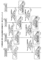
図11は、始点側設定処理に関わる伝送装置4の処理動作の一例を示すフローチャートである。尚、第1の伝送装置4Aを始点とし、第3の伝送装置4Cを終点とする。図11において伝送装置4内の制御部44は、パケットカード11を通じてパケットNW2からフレームを受信したか否かを判定する(ステップS31)。制御部44は、フレームを受信した場合(ステップS31肯定)、受信フレーム内の宛先MACアドレス毎の受信パケットの流量を監視する(ステップS32)。   FIG. 11 is a flowchart illustrating an example of a processing operation of the transmission apparatus 4 related to the start point side setting process. The first transmission device 4A is a starting point, and the third transmission device 4C is an end point. In FIG. 11, the control unit 44 in the transmission device 4 determines whether or not a frame is received from the packet NW2 through the packet card 11 (step S31). When the frame is received (Yes at Step S31), the control unit 44 monitors the flow rate of the received packet for each destination MAC address in the received frame (Step S32).

制御部44は、MACテーブル43Aを参照し、受信パケットの宛先MACアドレスに対応する転送先のパケットカード11を抽出する(ステップS33)。更に、制御部44は、第1の判定部51にて受信パケットの流量が所定閾値を超えたか否かを判定する(ステップS34)。制御部44は、受信パケットの流量が所定閾値を超えた場合(ステップS34肯定)、変換テーブル43Bを参照し、設定部53にて転送先のパケットカード11に対応した転送先のOTNカード12があるか否かを判定する(ステップS35)。   The control unit 44 refers to the MAC table 43A, and extracts the transfer destination packet card 11 corresponding to the destination MAC address of the received packet (step S33). Furthermore, the control unit 44 determines whether or not the flow rate of the received packet has exceeded a predetermined threshold at the first determination unit 51 (step S34). When the flow rate of the received packet exceeds the predetermined threshold (Yes at Step S34), the control unit 44 refers to the conversion table 43B, and sets the transfer destination OTN card 12 corresponding to the transfer destination packet card 11 in the setting unit 53. It is determined whether or not there is (step S35).

制御部44は、転送先のOTNカード12がある場合(ステップS35肯定)、転送先のOTNカード12に関わる設定可能なOTNパスの空き容量を確認する(ステップS36)。制御部44は、第2の判定部52にて受信パケットの流量が転送先のOTNカード12に関わる設定可能なOTNパスの空き容量未満であるか否かを判定する(ステップS37)。   When there is the transfer-destination OTN card 12 (Yes in step S35), the control unit 44 checks the available capacity of the settable OTN path related to the transfer-destination OTN card 12 (step S36). The control unit 44 determines whether or not the flow rate of the received packet is less than the available capacity of the settable OTN path related to the transfer destination OTN card 12 in the second determination unit 52 (step S37).

制御部44は、受信パケットの流量が設定可能なOTNパスの空き容量未満の場合(ステップS37肯定)、受信パケットの転送先として設定可能なOTNパスを確認すべく、パス確認処理を実行する(ステップS39)。尚、パス確認処理は、設定可能なOTNパスを確認すべく、パス確認要求を送信した後、そのパス確認要求に対するパス確認応答を受信した場合に、設定可能なOTNパスを確認できる。例えば、図8に示すステップS111、S112、S121及びS123等の処理を実行する。   When the flow rate of the received packet is less than the free capacity of the settable OTN path (Yes at Step S37), the control unit 44 executes a path check process to check the OTN path that can be set as the transfer destination of the received packet ( Step S39). Note that the path confirmation process can confirm the settable OTN path when a path confirmation response to the path confirmation request is received after transmitting the path confirmation request to confirm the settable OTN path. For example, processes such as steps S111, S112, S121, and S123 shown in FIG. 8 are executed.

更に、制御部44は、パス確認処理にて設定可能なOTNパスを確認後、受信フレームの転送先として設定可能なOTNパスを設定すべく、パス設定処理を実行し(ステップS40)、図11に示す処理動作を終了する。尚、パス設定処理は、パス確認済みの設定可能なOTNパスを設定すべく、パス設定要求を送信した後、そのパス設定要求に対するパス設定応答を受信した場合に、OTNパスを設定できる。例えば、図9に示すステップS131、S138及びS140等の処理を実行する。その結果、伝送装置4は、OTNNW3の設定中のOTNパスで受信フレームを転送できる。   Further, after confirming the OTN path that can be set in the path confirmation process, the control unit 44 executes the path setting process to set the OTN path that can be set as the transfer destination of the received frame (step S40). The processing operation shown in FIG. Note that the path setting process can set an OTN path when a path setting request is transmitted after a path setting request is transmitted in order to set a settable OTN path whose path has been confirmed. For example, processing such as steps S131, S138, and S140 shown in FIG. 9 is executed. As a result, the transmission apparatus 4 can transfer the received frame through the OTN path in which the OTNNW 3 is being set.

制御部44は、パケットカード11を通じてフレームを受信しなかった場合(ステップS31否定)、図11に示す処理動作を終了する。制御部44は、受信パケットの流量が所定閾値を超えなかった場合(ステップS34否定)、転送先のパケットカード11に受信フレームを転送し(ステップS41)、図11に示す処理動作を終了する。その結果、伝送装置4は、パケットNW2のパケットパスで受信フレームを伝送できる。   When the control unit 44 does not receive the frame through the packet card 11 (No at Step S31), the control unit 44 ends the processing operation illustrated in FIG. If the flow rate of the received packet does not exceed the predetermined threshold (No at Step S34), the control unit 44 transfers the received frame to the transfer destination packet card 11 (Step S41), and ends the processing operation illustrated in FIG. As a result, the transmission device 4 can transmit the received frame through the packet path of the packet NW2.

制御部44は、転送先のパケットカード11に対応した転送先OTNカードがない場合(ステップS35否定)、転送先のパケットカード11に受信フレームを転送すべく、ステップS41に移行する。制御部44は、受信パケットの流量が空き容量未満でない場合(ステップS37否定)、転送先のパケットカード11に受信フレームを転送すべく、ステップS41に移行する。   If there is no transfer destination OTN card corresponding to the transfer destination packet card 11 (No at Step S35), the control unit 44 proceeds to Step S41 to transfer the received frame to the transfer destination packet card 11. If the flow rate of the received packet is not less than the free capacity (No at Step S37), the control unit 44 proceeds to Step S41 to transfer the received frame to the transfer destination packet card 11.

図11において伝送装置4は、受信パケットの流量が所定閾値を超え、受信パケットの宛先MACアドレスのパケットカード11に対応する転送先のOTNカード12があるか否かを判定する。伝送装置4は、転送先のOTNカードがある場合、受信パケットの流量がOTNパスの空き容量未満であるか否かを判定する。そして、伝送装置4は、受信パケットの流量がOTNパスの空き容量未満の場合、転送先のOTNカード12を通じてOTNパスを設定する。その結果、伝送装置4は、受信パケットの流量が所定閾値を超えた場合に、受信パケットをOTNパスで転送できる。   In FIG. 11, the transmission device 4 determines whether or not the flow rate of the received packet exceeds a predetermined threshold and there is a transfer destination OTN card 12 corresponding to the packet card 11 of the destination MAC address of the received packet. When there is a transfer destination OTN card, the transmission device 4 determines whether or not the flow rate of the received packet is less than the free capacity of the OTN path. When the flow rate of the received packet is less than the free space of the OTN path, the transmission device 4 sets the OTN path through the transfer destination OTN card 12. As a result, the transmission device 4 can transfer the received packet through the OTN path when the flow rate of the received packet exceeds a predetermined threshold.

伝送装置4は、受信パケットの宛先MACアドレスのパケットカード11に対応する転送先のOTNカード12がない場合、転送先のパケットカード11を通じてパケットパスで受信パケットを伝送する。その結果、伝送装置4は、転送先のOTNカード12がない場合、受信パケットをパケットパスで伝送できる。   When there is no transfer destination OTN card 12 corresponding to the packet card 11 of the destination MAC address of the received packet, the transmission device 4 transmits the received packet through the packet path 11 through the transfer destination packet card 11. As a result, the transmission device 4 can transmit the received packet through the packet path when there is no transfer destination OTN card 12.

伝送装置4は、受信パケットの流量が所定閾値を超えていない場合、受信パケット内の宛先MACアドレスに対応した転送先のパケットカード11を通じて受信パケットを伝送する。その結果、伝送装置4は、受信パケットの流量が所定閾値を超えていない場合、受信パケットをパケットパスで伝送できる。   When the flow rate of the received packet does not exceed the predetermined threshold, the transmission device 4 transmits the received packet through the transfer destination packet card 11 corresponding to the destination MAC address in the received packet. As a result, the transmission device 4 can transmit the received packet through the packet path when the flow rate of the received packet does not exceed the predetermined threshold.

伝送装置4は、受信パケットの流量がOTNパスの空き容量未満でない場合、転送先のパケットカード11を通じて受信パケットを伝送する。その結果、伝送装置4は、受信パケットをパケットパスで伝送できる。   When the flow rate of the received packet is not less than the free space of the OTN path, the transmission device 4 transmits the received packet through the transfer destination packet card 11. As a result, the transmission device 4 can transmit the received packet through the packet path.

図12は、始点側転送処理に関わる伝送装置4の処理動作の一例を示すフローチャートである。尚、説明の便宜上、伝送装置4は、受信パケットをOTNパスで転送しているものとする。   FIG. 12 is a flowchart illustrating an example of the processing operation of the transmission apparatus 4 related to the start point side transfer process. For convenience of explanation, it is assumed that the transmission device 4 transfers the received packet through the OTN path.

図12において伝送装置4内の制御部44は、パケットカード11を通じて受信フレームを受信したか否かを判定する(ステップS51)。制御部44は、受信フレームを受信した場合(ステップS51肯定)、受信フレーム内の宛先MACアドレス毎の受信パケットの流量を監視する(ステップS52)。   In FIG. 12, the control unit 44 in the transmission device 4 determines whether or not a received frame has been received through the packet card 11 (step S51). When receiving the received frame (Yes at Step S51), the control unit 44 monitors the flow rate of the received packet for each destination MAC address in the received frame (Step S52).

制御部44は、宛先MACアドレス毎の受信パケットの流量が所定閾値未満であるか否かを判定する(ステップS53)。制御部44は、宛先MACアドレス毎の受信パケットの流量が所定閾値未満でない場合(ステップS53否定)、設定中のOTNパスに関わる転送先のOTNカード12に受信パケットを転送し(ステップS54)、図12に示す処理動作を終了する。   The control unit 44 determines whether or not the flow rate of received packets for each destination MAC address is less than a predetermined threshold (step S53). When the flow rate of the received packet for each destination MAC address is not less than the predetermined threshold (No at Step S53), the control unit 44 transfers the received packet to the transfer destination OTN card 12 related to the OTN path being set (Step S54). The processing operation shown in FIG.

制御部44は、受信パケットの流量が所定閾値未満の場合(ステップS53肯定)、MACテーブル43Aを参照し、受信パケットの宛先MACアドレスに対応した転送先のパケットカード12に受信パケットを転送する(ステップS55)。更に、制御部44は、受信フレーム転送で設定したクロスコネクトを削除し(ステップS56)、転送先のOTNカード12からパス削除要求を送信し(ステップS57)、図12に示す処理動作を終了する。制御部44は、パケットカード11を通じて受信フレームを受信しなかった場合(ステップS51否定)、図12に示す処理動作を終了する。   When the flow rate of the received packet is less than the predetermined threshold (Yes at Step S53), the control unit 44 refers to the MAC table 43A and transfers the received packet to the packet card 12 that is the transfer destination corresponding to the destination MAC address of the received packet ( Step S55). Further, the control unit 44 deletes the cross-connect set by the received frame transfer (step S56), transmits a path deletion request from the transfer destination OTN card 12 (step S57), and ends the processing operation shown in FIG. . When the control unit 44 does not receive the received frame through the packet card 11 (No at Step S51), the control unit 44 ends the processing operation illustrated in FIG.

図12において伝送装置4は、受信パケットを設定中のOTNパスで転送中に、受信パケットの流量が所定閾値未満となった場合、設定中のOTNパス内のクロスコネクトを削除する。そして、伝送装置4は、受信パケットを転送先のパケットカード11を通じてパケットパスで伝送する。その結果、伝送装置4は、受信パケットの流量が所定閾値未満になると、受信パケットを通常のパケットパスに切替えて伝送するため、OTNNW3へのトラフィックを軽減できる。   In FIG. 12, the transmission device 4 deletes the cross-connect in the OTN path being set when the flow rate of the received packet becomes less than a predetermined threshold during transfer of the received packet on the OTN path being set. Then, the transmission device 4 transmits the received packet through the packet card 11 of the transfer destination through the packet path. As a result, when the flow rate of the received packet becomes less than the predetermined threshold, the transmission device 4 switches the received packet to the normal packet path and transmits it, so that traffic to the OTNNW 3 can be reduced.

伝送装置4は、受信パケットを設定中のOTNパスで転送中に、受信パケットの流量が所定閾値未満にならなかった場合、設定中のOTNパスで受信パケットを転送する。その結果、伝送装置4は、設定中のOTNパスで継続して受信パスを転送できる。   If the flow rate of the received packet does not become less than the predetermined threshold during transfer of the received packet through the set OTN path, the transmission device 4 transfers the received packet through the set OTN path. As a result, the transmission apparatus 4 can continuously transfer the reception path using the set OTN path.

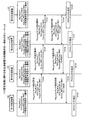
図13は、中継点側設定処理に関わる各伝送装置4の処理動作の一例を示すフローチャートである。尚、第1の伝送装置4Aを始点とし、第3の伝送装置4Cを終点とした場合、中継点の伝送装置4は、例えば、第4の伝送装置4D及び第5の伝送装置4Eである。   FIG. 13 is a flowchart illustrating an example of the processing operation of each transmission device 4 related to the relay point side setting process. When the first transmission device 4A is the starting point and the third transmission device 4C is the end point, the relay point transmission devices 4 are, for example, the fourth transmission device 4D and the fifth transmission device 4E.

図13において伝送装置4内の制御部44は、OTNカード12からパス確認要求を受信したか否かを判定する(ステップS61)。制御部44は、パス確認要求を受信した場合(ステップS61肯定)、パス確認要求内の宛先MACアドレスを抽出する(ステップS62)。   In FIG. 13, the control unit 44 in the transmission apparatus 4 determines whether a path confirmation request is received from the OTN card 12 (step S61). When receiving the path confirmation request (Yes at Step S61), the control unit 44 extracts the destination MAC address in the path confirmation request (Step S62).

制御部44は、MACテーブル43Aを参照し、宛先MACアドレスに対応する転送先のパケットカード11を抽出する(ステップS63)。制御部44は、変換テーブル43Bを参照し、抽出した転送先のパケットカード11に対応する転送先のOTNカード12があるか否かを判定する(ステップS64)。   The control unit 44 refers to the MAC table 43A and extracts the transfer destination packet card 11 corresponding to the destination MAC address (step S63). The control unit 44 refers to the conversion table 43B and determines whether there is a transfer destination OTN card 12 corresponding to the extracted transfer destination packet card 11 (step S64).

制御部44は、転送先のパケットカード11に対応する転送先のOTNカード12がある場合(ステップS64肯定)、転送先のOTNカード12に関わるOTNパスの空き容量を確認する(ステップS65)。制御部44は、受信パケットの流量が設定可能なOTNパスの空き容量未満であるか否かを判定する(ステップS66)。   When there is a transfer destination OTN card 12 corresponding to the transfer destination packet card 11 (Yes in step S64), the control unit 44 checks the free capacity of the OTN path related to the transfer destination OTN card 12 (step S65). The control unit 44 determines whether or not the flow rate of the received packet is less than the free capacity of the settable OTN path (step S66).

制御部44は、受信パケットの流量が設定可能なOTNパスの空き容量未満の場合(ステップS66肯定)、設定可能なOTNパスを確認すべく、パス確認処理を実行する(ステップS67)。尚、パス確認処理は、設定可能なOTNパスを確認すべく、パス確認要求を送信した後、そのパス確認要求に対するパス確認応答を受信した場合に、設定可能なOTNパスを確認できる。例えば、図8に示すステップS113、S114、S119及びS122等の処理を実行する。   When the flow rate of the received packet is less than the free capacity of the settable OTN path (Yes at Step S66), the control unit 44 executes a path check process to check the settable OTN path (Step S67). Note that the path confirmation process can confirm the settable OTN path when a path confirmation response to the path confirmation request is received after transmitting the path confirmation request to confirm the settable OTN path. For example, processes such as steps S113, S114, S119, and S122 shown in FIG. 8 are executed.

制御部44は、パス確認処理にて設定可能なOTNパスを確認後、受信フレームの転送先として設定可能なOTNパスを設定すべく、パス設定処理を実行し(ステップS68)、図13に示す処理動作を終了する。尚、パス設定処理は、パス確認済みの設定可能なOTNパスを設定すべく、パス設定要求を送信した後、そのパス設定要求に対するパス設定応答を受信した場合に、OTNパスを設定できる。例えば、図9に示すステップS132、S136及びS139等の処理を実行する。その結果、伝送装置4は、OTNNW3の設定中のOTNパスで受信フレームを転送できる。   After confirming the OTN path that can be set in the path confirmation process, the control unit 44 executes the path setting process to set the OTN path that can be set as the transfer destination of the received frame (step S68), as shown in FIG. The processing operation is terminated. Note that the path setting process can set an OTN path when a path setting request is transmitted after a path setting request is transmitted in order to set a settable OTN path whose path has been confirmed. For example, processing such as steps S132, S136, and S139 shown in FIG. 9 is executed. As a result, the transmission apparatus 4 can transfer the received frame through the OTN path in which the OTNNW 3 is being set.

制御部44は、転送先のパケットカード11に対応する転送先のOTNカード12がない場合(ステップS64否定)、パス設定要求を受信したOTNカード12と転送先パケットカード11とを接続する(ステップS69)。更に、制御部44は、パス設定応答内にTS番号を設定し、パス設定要求を受信したOTNカード12経由でパス設定応答を送信し(ステップS70)、図13に示す処理動作を終了する。   When there is no transfer destination OTN card 12 corresponding to the transfer destination packet card 11 (No at Step S64), the control unit 44 connects the OTN card 12 that has received the path setting request and the transfer destination packet card 11 (Step S64). S69). Further, the control unit 44 sets the TS number in the path setting response, transmits the path setting response via the OTN card 12 that has received the path setting request (step S70), and ends the processing operation shown in FIG.

制御部44は、空き容量が受信フレームの流量以上でない場合(ステップS66否定)、パス設定要求を受信したOTNカード12と転送先パケットカード11とを接続すべく、ステップS69に移行する。   If the available capacity is not equal to or greater than the flow rate of the received frame (No at Step S66), the control unit 44 proceeds to Step S69 to connect the OTN card 12 that has received the path setting request and the transfer destination packet card 11.

制御部44は、OTNカード12からパス設定要求を受信しなかった場合(ステップS61否定)、OTNカード12からパス削除要求を受信したか否かを判定する(ステップS71)。制御部44は、パス削除要求を受信した場合(ステップS71肯定)、パス削除要求内のMACアドレスを抽出する(ステップS72)。更に、制御部44は、MACテーブル43Aを参照し、パス削除要求内のMACアドレスに対応する転送先のパケットカード11を抽出する(ステップS73)。   When the control unit 44 has not received a path setting request from the OTN card 12 (No at Step S61), the control unit 44 determines whether a path deletion request has been received from the OTN card 12 (Step S71). When receiving the path deletion request (Yes at Step S71), the control unit 44 extracts the MAC address in the path deletion request (Step S72). Further, the control unit 44 refers to the MAC table 43A, and extracts the packet card 11 of the transfer destination corresponding to the MAC address in the path deletion request (step S73).

制御部44は、パケットカード11と転送先のパケットカード11とを接続し(ステップS74)、クロスコネクトを削除する(ステップS75)。そして、制御部44は、クロスコネクト削除前に設定していたOTNカード12からパス削除要求を送信し(ステップS76)、図13に示す処理動作を終了する。制御部44は、パス削除要求を受信しなかった場合(ステップS71否定)、図13に示す処理動作を終了する。   The control unit 44 connects the packet card 11 and the transfer destination packet card 11 (step S74), and deletes the cross-connect (step S75). Then, the control unit 44 transmits a path deletion request from the OTN card 12 set before the cross-connect deletion (step S76), and ends the processing operation shown in FIG. When the control unit 44 does not receive the path deletion request (No at Step S71), the control unit 44 ends the processing operation illustrated in FIG.

図13において伝送装置4は、パス確認要求を受信した場合、パス確認要求内の受信パケットの宛先MACアドレスのパケットカード11に対応する転送先のOTNカード12があるか否かを判定する。伝送装置4は、転送先のOTNカード12がある場合、受信パケットの流量が設定可能なOTNパスの空き容量未満であるか否かを判定する。そして、伝送装置4は、受信パケットの流量が設定可能なOTNパスの空き容量未満の場合、転送先のOTNカード12を通じて設定可能なOTNパスを確認する。そして、伝送装置4は、設定可能なOTNパスのパス設定要求に対してパス設定応答を受信した場合、OTNパスを設定する。その結果、伝送装置4は、受信パケットを転送するOTNパスを設定できる。   In FIG. 13, when the transmission device 4 receives the path confirmation request, the transmission device 4 determines whether or not there is a transfer destination OTN card 12 corresponding to the packet card 11 of the destination MAC address of the received packet in the path confirmation request. When there is the transfer destination OTN card 12, the transmission device 4 determines whether or not the flow rate of the received packet is less than the free capacity of the settable OTN path. Then, when the flow rate of the received packet is less than the free capacity of the settable OTN path, the transmission device 4 confirms the settable OTN path through the transfer destination OTN card 12. When the transmission apparatus 4 receives a path setting response in response to a path setting request for a settable OTN path, the transmission apparatus 4 sets an OTN path. As a result, the transmission device 4 can set an OTN path for transferring the received packet.

伝送装置4は、受信パケットの宛先MACアドレスのパケットカード11に対応する転送先のOTNカード12がない場合、転送先としてパケットカード11と接続する。その結果、伝送装置4は、転送先のOTNカード12がない場合、OTNパスで受信した受信パケットをパケットパスで中継できる。   When there is no transfer destination OTN card 12 corresponding to the packet card 11 of the destination MAC address of the received packet, the transmission device 4 connects to the packet card 11 as the transfer destination. As a result, when there is no transfer destination OTN card 12, the transmission apparatus 4 can relay the received packet received through the OTN path through the packet path.

伝送装置4は、受信パケットの流量が設定可能なOTNパスの空き容量未満でない場合、転送先としてパケットカード11と接続する。その結果、伝送装置4は、OTNパスで受信した受信パケットをパケットパスで転送先に中継できる。   The transmission device 4 is connected to the packet card 11 as a transfer destination when the flow rate of the received packet is not less than the free capacity of the settable OTN path. As a result, the transmission device 4 can relay the received packet received via the OTN path to the transfer destination via the packet path.

図14は、終点側設定処理に関わる伝送装置4の処理動作の一例を示すフローチャートである。尚、終点の伝送装置4は、例えば、第3の伝送装置4Cとする。   FIG. 14 is a flowchart illustrating an example of a processing operation of the transmission apparatus 4 related to the end point side setting process. The end point transmission apparatus 4 is, for example, the third transmission apparatus 4C.

図14において伝送装置4内の制御部44は、OTNカード12からパス設定要求を受信したか否かを判定する(ステップS91)。制御部44は、パス設定要求を受信した場合(ステップS91肯定)、パス設定要求内の宛先MACアドレスを抽出する(ステップS92)。   In FIG. 14, the control unit 44 in the transmission apparatus 4 determines whether or not a path setting request has been received from the OTN card 12 (step S91). When receiving the path setting request (Yes at Step S91), the control unit 44 extracts the destination MAC address in the path setting request (Step S92).

制御部44は、MACテーブル43Aを参照し、宛先MACアドレスに対応する転送先のパケットカード11を抽出する(ステップS93)。制御部44は、パス設定要求を受信したOTNカード12と転送先のパケットカード11とを接続し(ステップS94)、OTNパスのTS番号を設定する(ステップS95)。   The control unit 44 refers to the MAC table 43A and extracts the transfer destination packet card 11 corresponding to the destination MAC address (step S93). The control unit 44 connects the OTN card 12 that has received the path setting request to the transfer destination packet card 11 (step S94), and sets the TS number of the OTN path (step S95).

更に、制御部44は、設定TS番号を用いてクロスコネクトを設定し(ステップS96)、パス設定応答内にTS番号を設定し、パス設定要求を受信したOTNカード12からパス設定応答を送信し(ステップS97)、図14に示す処理動作を終了する。   Further, the control unit 44 sets a cross-connect using the set TS number (step S96), sets the TS number in the path setting response, and transmits a path setting response from the OTN card 12 that has received the path setting request. (Step S97), the processing operation shown in FIG. 14 is terminated.

制御部44は、OTNカード12からパス設定要求を受信しなかった場合(ステップS91否定)、OTNカード12からパス削除要求を受信したか否かを判定する(ステップS98)。制御部44は、パス削除要求を受信した場合(ステップS98肯定)、パス削除要求内のMACアドレスを抽出する(ステップS99)。更に、制御部44は、MACテーブル43Aを参照し、パス削除要求内のMACアドレスに対応する転送先のパケットカード11を抽出する(ステップS100)。   When the control unit 44 has not received a path setting request from the OTN card 12 (No at Step S91), the control unit 44 determines whether a path deletion request has been received from the OTN card 12 (Step S98). When receiving the path deletion request (Yes at Step S98), the control unit 44 extracts the MAC address in the path deletion request (Step S99). Furthermore, the control unit 44 refers to the MAC table 43A and extracts the packet card 11 that is the transfer destination corresponding to the MAC address in the path deletion request (step S100).

制御部44は、パケットカード11と転送先のパケット11とを接続し(ステップS101)、クロスコネクトを削除し(ステップS102)、図14に示す処理動作を終了する。制御部44は、OTNカード12からパス削除要求を受信しなかった場合(ステップS98否定)、図14に示す処理動作を終了する。   The control unit 44 connects the packet card 11 and the transfer destination packet 11 (step S101), deletes the cross-connect (step S102), and ends the processing operation shown in FIG. When the control unit 44 does not receive the path deletion request from the OTN card 12 (No at Step S98), the control unit 44 ends the processing operation illustrated in FIG.

図14において終点の伝送装置4は、パス設定要求を受信した場合、パス設定要求に応じてクロスコネクトを設定し、パス設定応答を返信する。終点の伝送装置4は、対向側の伝送装置4との間でクロスコネクトを順次設定し、OTNパスを設定する。その結果、伝送装置4は、OTNパスを自動設定できる。   In FIG. 14, when receiving the path setting request, the transmission apparatus 4 at the end point sets a cross-connect in response to the path setting request and returns a path setting response. The transmission apparatus 4 at the end point sequentially sets cross-connects with the transmission apparatus 4 on the opposite side, and sets an OTN path. As a result, the transmission device 4 can automatically set the OTN path.

終点の伝送装置4は、パス削除要求を受信した場合、パス削除要求に応じて設定中のクロスコネクトを削除する。その結果、伝送装置4は、設定中のOTNパスを削除できる。   When receiving the path deletion request, the transmission apparatus 4 at the end point deletes the cross-connect being set according to the path deletion request. As a result, the transmission apparatus 4 can delete the OTN path being set.

本実施例の伝送装置4は、受信パケットの流量が所定閾値を超えた場合に、受信パケット内の宛先MACアドレスに基づき、受信パケットを転送すべく、OTNパスを設定する。その結果、伝送装置4は、受信パケットの流量が増加した場合でも、OTNパスを自動設定し、受信パケットをOTNパスで転送できる。例えば、パケットNW2側のパスが不足している場合に、その容量不足分をOTNパスで補える。しかも、伝送システム1内の伝送装置4が増加した場合でも、従来技術に比較してOTNパス自動設定の処理負荷を軽減できる。   The transmission device 4 of this embodiment sets an OTN path to transfer a received packet based on a destination MAC address in the received packet when the flow rate of the received packet exceeds a predetermined threshold. As a result, the transmission device 4 can automatically set the OTN path and transfer the received packet through the OTN path even when the flow rate of the received packet increases. For example, when the path on the packet NW2 side is insufficient, the capacity shortage can be compensated by the OTN path. In addition, even when the number of transmission apparatuses 4 in the transmission system 1 increases, the processing load for OTN path automatic setting can be reduced as compared with the prior art.

伝送装置4は、受信パケット内の宛先MACアドレスをOTNフレーム内に挿入し、OTNフレーム内の宛先MACアドレスに基づき、OTNパスの設定を要求し、設定要求に対応する応答に応じてOTNパスを設定する。その結果、伝送装置4は、受信パケット内の宛先MACアドレスを利用してOTNパスを設定できる。   The transmission device 4 inserts the destination MAC address in the received packet into the OTN frame, requests the setting of the OTN path based on the destination MAC address in the OTN frame, and sets the OTN path according to the response corresponding to the setting request. Set. As a result, the transmission device 4 can set the OTN path using the destination MAC address in the received packet.

伝送装置4は、受信パケットの流量が所定閾値を超え、かつ、受信パケットの流量がOTNパスの空き容量未満の場合に、受信パケット内の宛先MACアドレスに基づき、受信パケットを転送すべく、OTNパスを設定する。その結果、伝送装置4は、受信パケットをOTNパスで転送できる。   When the flow rate of the received packet exceeds a predetermined threshold and the flow rate of the received packet is less than the free capacity of the OTN path, the transmission device 4 transmits the received packet based on the destination MAC address in the received packet. Set the path. As a result, the transmission device 4 can transfer the received packet through the OTN path.

伝送装置4は、受信フレーム内の宛先MACアドレス毎に受信パケットの流量を測定する。その結果、伝送装置4は、受信パケット毎の流量を認識できる。   The transmission device 4 measures the flow rate of the received packet for each destination MAC address in the received frame. As a result, the transmission device 4 can recognize the flow rate for each received packet.

伝送装置4は、受信パケット内の宛先MACアドレスに基づき、受信パケットを転送するOTNパスを設定中に、パケットカード11にて受信パケットの流量が所定閾値を超えなくなった場合に、OTNパスからパケットパスに切り替える。その結果、伝送装置4は、OTNNW3へのトラフィック量を軽減できる。   The transmission device 4 sets the packet from the OTN path when the flow rate of the received packet does not exceed a predetermined threshold in the packet card 11 while setting the OTN path for transferring the received packet based on the destination MAC address in the received packet. Switch to the path. As a result, the transmission device 4 can reduce the amount of traffic to the OTNNW 3.

尚、上記実施例では、受信パケットの流量が所定閾値を超えると、受信パケット内の宛先MACアドレスの転送先のパケットカード11に対応する転送先のOTNカード12を抽出し、抽出した転送先のOTNカード11を通じてOTNパスを自動設定する。OTNパスを自動設定する方法としては、例えば、Neighbor Discovery機能、Topology Table機能、Path Computation機能及びSignaling機能等のGMPLSを利用してOTNパスを自動設定できる。Neighbor Discovery機能は、例えば、LMPプロトコルを利用してOTNNW3内のリンクを認識する機能である。Topology Table機能は、例えば、OSPF−TEプロトコルを利用してOTNNW3内のトポロジ情報を生成する機能である。Path Computation機能は、例えば、OSPF−TEで作成したトポロジ情報及びCSPF(Constraint Shortest Path Fast)アルゴリズムを使用して宛先までの最短経路を探索する機能である。Signaling機能は、RSVP−TEプロトコルを使用して最短経路情報からエンドトゥエンドのOTNパスを設定する機能である。   In the above embodiment, when the flow rate of the received packet exceeds the predetermined threshold, the transfer destination OTN card 12 corresponding to the transfer destination packet card 11 of the destination MAC address in the received packet is extracted, and the extracted transfer destination An OTN path is automatically set through the OTN card 11. As a method for automatically setting an OTN path, for example, an OTN path can be automatically set using GMPLS such as a Neighbor Discovery function, a Topology Table function, a Path Computation function, and a Signaling function. The Neighbor Discovery function is a function that recognizes a link in the OTNNW 3 using, for example, the LMP protocol. The Topology Table function is a function for generating topology information in the OTNNW 3 using, for example, the OSPF-TE protocol. The Path Computation function is a function that searches for the shortest path to a destination using, for example, topology information created by OSPF-TE and a CSPF (Constraint Shortest Path Fast) algorithm. The Signaling function is a function for setting an end-to-end OTN path from the shortest path information using the RSVP-TE protocol.

しかしながら、GMPLSを使用してOTNパスを自動設定できるものの、OSPF−TEでOTNNW3全体のトポロジを認識した上で最短経路を計算する必要がある。OTNNW3内の全ての伝送装置4がOTNNW3内の全リンクのトポロジを認識する必要があるため、リアルタイムにトポロジ情報を認識するにはOSPF−TEプロトコルの処理負荷が大きくなる。しかも、OTNNW3内の伝送装置4の数が増えるに連れて、OSPF−TEの処理負荷及び最短経路の処理負荷が大きくなる。これに対して、本実施例では、GMPLSを使用しなくても、OTNパスを自動設定できるため、自動設定に要する処理負担が軽減できる。   However, although the OTN path can be automatically set using GMPLS, it is necessary to calculate the shortest path after recognizing the topology of the entire OTNNW 3 by OSPF-TE. Since all the transmission apparatuses 4 in the OTNNW 3 need to recognize the topology of all the links in the OTNNW 3, the processing load of the OSPF-TE protocol increases in order to recognize the topology information in real time. In addition, as the number of transmission apparatuses 4 in the OTNNW 3 increases, the processing load of OSPF-TE and the processing load of the shortest path increase. On the other hand, in this embodiment, since the OTN path can be automatically set without using GMPLS, the processing load required for the automatic setting can be reduced.

上記実施例では、パケットNW2とOTNNW3とを同一トポロジで構成する伝送システム1を例示したが、同一トポロジで構成されなくても、OTNパスを自動設定できる。   In the above embodiment, the transmission system 1 in which the packet NW2 and the OTNNW3 are configured with the same topology is illustrated, but the OTN path can be automatically set even if the packets NW2 and OTNNW3 are not configured with the same topology.

上記実施例では、パケットNW2としてEthernet(登録商標)のNWを例示したが、これらに限定されるものではなく、パケット内に宛先MACアドレスを有するNWであれば適用可能である。   In the above embodiment, an Ethernet (registered trademark) NW is exemplified as the packet NW2, but the present invention is not limited to this, and any NW having a destination MAC address in the packet can be applied.

また、図示した各部の各構成要素は、必ずしも物理的に図示の如く構成されていることを要しない。すなわち、各部の分散・統合の具体的形態は図示のものに限られず、その全部又は一部を、各種の負荷や使用状況等に応じて、任意の単位で機能的又は物理的に分散・統合して構成することができる。   In addition, each component of each part illustrated does not necessarily need to be physically configured as illustrated. In other words, the specific form of distribution / integration of each part is not limited to the one shown in the figure, and all or a part thereof may be functionally or physically distributed / integrated in arbitrary units according to various loads and usage conditions. Can be configured.

更に、各装置で行われる各種処理機能は、CPU(Central Processing Unit)(又はMPU(Micro Processing Unit)、MCU(Micro Controller Unit)等のマイクロ・コンピュータ)上で、その全部又は任意の一部を実行するようにしても良い。また、各種処理機能は、CPU(又はMPU、MCU等のマイクロ・コンピュータ)で解析実行するプログラム上、又はワイヤードロジックによるハードウェア上で、その全部又は任意の一部を実行するようにしても良いことは言うまでもない。   Furthermore, various processing functions performed in each device are performed on a CPU (Central Processing Unit) (or a microcomputer such as an MPU (Micro Processing Unit), MCU (Micro Controller Unit), etc.) in whole or in part. You may make it perform. Various processing functions may be executed entirely or arbitrarily on a program that is analyzed and executed by a CPU (or a microcomputer such as an MPU or MCU) or hardware based on wired logic. Needless to say.

1 伝送システム
2 パケットNW
3 OTNNW
4 伝送装置
11 パケットカード
11A 第1のパケットカード
11B 第2のパケットカード
12 OTNカード
51 第1の判定部
52 第2の判定部
53 設定部
1 Transmission system 2 Packet NW
3 OTNNNW
4 Transmission Device 11 Packet Card 11A First Packet Card 11B Second Packet Card 12 OTN Card 51 First Determination Unit 52 Second Determination Unit 53 Setting Unit

Claims (9)

第1の信号を伝送する第1の回線と接続する複数の第1の通信部と、
前記第1の信号を挿入可能にする第2の信号を伝送する第2の回線と接続する第2の通信部と、
前記第1の通信部にて前記第1の信号のデータ量が所定閾値を超えたか否かを判定する判定部と、
前記第1の信号のデータ量が前記所定閾値を超えた場合に、前記第1の信号内の宛先情報に基づき、前記第2の通信部にて、前記第1の信号を転送する前記第2の回線を設定する設定部と
を有することを特徴とする伝送装置。
A plurality of first communication units connected to a first line for transmitting a first signal;
A second communication unit connected to a second line for transmitting a second signal enabling insertion of the first signal;
A determination unit that determines whether or not a data amount of the first signal exceeds a predetermined threshold in the first communication unit;
When the data amount of the first signal exceeds the predetermined threshold, the second communication unit transfers the first signal based on the destination information in the first signal. And a setting unit for setting the line.
前記第1の信号のデータ量が前記所定閾値を超えた場合に、前記第1の信号のデータ量が前記第2の回線の空き容量未満であるか否かを判定する第1の判定部を更に有し、
前記設定部は、
前記第1の判定部にて前記第1の信号のデータ量が前記第2の回線の空き容量未満の場合に、前記第1の信号内の宛先情報に基づき、前記第2の通信部にて、前記第1の信号を転送すべく、前記第2の回線に設定することを特徴とする請求項1に記載の伝送装置。
A first determination unit configured to determine whether or not the data amount of the first signal is less than a free capacity of the second line when the data amount of the first signal exceeds the predetermined threshold; In addition,
The setting unit
When the data amount of the first signal is less than the free capacity of the second line at the first determination unit, based on the destination information in the first signal, at the second communication unit The transmission apparatus according to claim 1, wherein the transmission apparatus is set to the second line so as to transfer the first signal.
前記設定部は、
前記第1の信号内の宛先情報を前記第2の信号内に挿入し、前記第1の信号の宛先情報を挿入した前記第2の信号に関わる設定要求を対向側の伝送装置に送信し、前記対向側の伝送装置から前記設定要求に対する応答を受信した場合に、前記第1の信号を転送する前記第2の回線を設定することを特徴とする請求項1又は2に記載の伝送装置。
The setting unit
Inserting destination information in the first signal into the second signal, sending a setting request relating to the second signal into which the destination information of the first signal has been inserted, to the opposite transmission device; 3. The transmission apparatus according to claim 1, wherein the second line for transferring the first signal is set when a response to the setting request is received from the transmission apparatus on the opposite side.
前記第1の回線の前記第1の信号のデータ量を前記第1の信号内の宛先情報毎に監視する監視部を更に有することを特徴とする請求項1〜3の何れか一つに記載の伝送装置。   The monitoring unit that further monitors the data amount of the first signal of the first line for each destination information in the first signal. Transmission equipment. 前記設定部は、
前記第1の信号内の宛先情報に基づき、前記第1の信号を転送すべく、前記第2の回線に設定中に、前記判定部にて前記第1の信号のデータ量が所定閾値を超えなくなった場合に、前記第1の信号を前記第2の回線から前記第1の回線に切り替えるべく、前記第1の信号を前記第1の回線に設定することを特徴とする請求項1〜4の何れか一つに記載の伝送装置。
The setting unit
Based on the destination information in the first signal, the data amount of the first signal exceeds a predetermined threshold in the determination unit while setting the second line to transfer the first signal. 5. The first signal is set to the first line in order to switch the first signal from the second line to the first line when the first signal is lost. The transmission device according to any one of the above.
前記第1の回線と前記第2の回線とを同一トポロジで接続する伝送システム内に配置したことを特徴とする請求項1〜5の何れか一つに記載の伝送装置。   6. The transmission apparatus according to claim 1, wherein the transmission apparatus is arranged in a transmission system that connects the first line and the second line with the same topology. 前記第1の通信部は、
前記第1の信号としてパケットを伝送する、前記第1の回線としてのパケット網と接続すると共に、
前記第2の通信部は、
前記第2の信号としてOTNフレームを伝送する、前記第2の回線としてのOTN網と接続することを特徴とする請求項1〜6の何れか一つに記載の伝送装置。
The first communication unit is
A packet is transmitted as the first signal, connected to a packet network as the first line, and
The second communication unit is
The transmission apparatus according to claim 1, wherein the transmission apparatus is connected to an OTN network serving as the second line that transmits an OTN frame as the second signal.
第1の信号を伝送する第1の回線と接続する複数の第1の通信部と、前記第1の信号を挿入可能にする第2の信号を伝送する第2の回線と接続する第2の通信部とを有する伝送装置の伝送方法であって、
前記伝送装置は、
前記第1の通信部にて前記第1の信号のデータ量が所定閾値を超えたか否かを判定し、
前記第1の信号のデータ量が前記所定閾値を超えた場合に、前記第1の信号内の宛先情報に基づき、前記第2の通信部にて、前記第1の信号を転送する前記第2の回線を設定する
処理を実行することを特徴とする伝送方法。
A plurality of first communication units connected to a first line for transmitting a first signal, and a second line connected to a second line for transmitting a second signal enabling insertion of the first signal. A transmission method of a transmission device having a communication unit,
The transmission device is
Determining whether or not the data amount of the first signal exceeds a predetermined threshold in the first communication unit;
When the data amount of the first signal exceeds the predetermined threshold, the second communication unit transfers the first signal based on the destination information in the first signal. A transmission method characterized by executing a process of setting up a line of the network.
第1の信号を伝送する第1の回線と接続する複数の第1の通信部と、前記第1の信号を挿入可能にする第2の信号を伝送する第2の回線と接続する第2の通信部とを備えた複数の伝送装置を有する伝送システムであって、
各伝送装置は、
前記第1の通信部にて前記第1の信号のデータ量が所定閾値を超えたか否かを判定する判定部と、
前記第1の信号のデータ量が前記所定閾値を超えた場合に、前記第1の信号内の宛先情報を前記第2の信号内に挿入し、前記第1の信号の宛先情報を挿入した前記第2の信号に関わる設定要求を対向側の伝送装置に送信すると共に、前記対向側の伝送装置から前記設定要求に対する応答を受信した場合に、前記第1の信号を転送する前記第2の回線を設定する設定部と
を有することを特徴とする伝送システム。
A plurality of first communication units connected to a first line for transmitting a first signal, and a second line connected to a second line for transmitting a second signal enabling insertion of the first signal. A transmission system having a plurality of transmission devices including a communication unit,
Each transmission device
A determination unit that determines whether or not a data amount of the first signal exceeds a predetermined threshold in the first communication unit;
When the data amount of the first signal exceeds the predetermined threshold, the destination information in the first signal is inserted into the second signal, and the destination information of the first signal is inserted The second line that transmits the setting signal related to the second signal to the opposite transmission apparatus and transfers the first signal when a response to the setting request is received from the opposite transmission apparatus. And a setting unit for setting the transmission system.
JP2015134682A 2015-07-03 2015-07-03 Transmission equipment, transmission method and transmission system Pending JP2017017627A (en)

Priority Applications (2)

Application Number Priority Date Filing Date Title
JP2015134682A JP2017017627A (en) 2015-07-03 2015-07-03 Transmission equipment, transmission method and transmission system
US15/187,190 US20170005934A1 (en) 2015-07-03 2016-06-20 Apparatus and method for transferring data onto another network depending on an amount of data flow in a network

Applications Claiming Priority (1)

Application Number Priority Date Filing Date Title
JP2015134682A JP2017017627A (en) 2015-07-03 2015-07-03 Transmission equipment, transmission method and transmission system

Publications (1)

Publication Number Publication Date
JP2017017627A true JP2017017627A (en) 2017-01-19

Family

ID=57683092

Family Applications (1)

Application Number Title Priority Date Filing Date
JP2015134682A Pending JP2017017627A (en) 2015-07-03 2015-07-03 Transmission equipment, transmission method and transmission system

Country Status (2)

Country Link
US (1) US20170005934A1 (en)
JP (1) JP2017017627A (en)

Families Citing this family (2)

* Cited by examiner, † Cited by third party
Publication number Priority date Publication date Assignee Title
CN109428647B (en) * 2017-08-31 2020-04-14 华为技术有限公司 Method, device and storage medium for realizing fault cause positioning
US11689453B2 (en) * 2021-03-29 2023-06-27 Cisco Technology, Inc. Layer 2 virtual private network traffic steering over optical transport networks

Citations (4)

* Cited by examiner, † Cited by third party
Publication number Priority date Publication date Assignee Title
JP2002199007A (en) * 2000-10-12 2002-07-12 Lucent Technol Inc Method used in packet network node
JP2003250143A (en) * 2002-02-26 2003-09-05 Cuebs:Kk Moving picture distribution apparatus and method, and program for controlling moving picture distribution apparatus
JP2011250143A (en) * 2010-05-27 2011-12-08 Fujitsu Ltd Switching apparatus and switching method
US20140147106A1 (en) * 2012-11-27 2014-05-29 Infinera Corporation Rapid recovery in packet and optical networks

Family Cites Families (2)

* Cited by examiner, † Cited by third party
Publication number Priority date Publication date Assignee Title
US7583664B2 (en) * 2004-12-28 2009-09-01 Michael Ho Techniques for transmitting and receiving traffic over advanced switching compatible switch fabrics
US9942097B2 (en) * 2015-01-05 2018-04-10 Brocade Communications Systems LLC Power management in a network of interconnected switches

Patent Citations (4)

* Cited by examiner, † Cited by third party
Publication number Priority date Publication date Assignee Title
JP2002199007A (en) * 2000-10-12 2002-07-12 Lucent Technol Inc Method used in packet network node
JP2003250143A (en) * 2002-02-26 2003-09-05 Cuebs:Kk Moving picture distribution apparatus and method, and program for controlling moving picture distribution apparatus
JP2011250143A (en) * 2010-05-27 2011-12-08 Fujitsu Ltd Switching apparatus and switching method
US20140147106A1 (en) * 2012-11-27 2014-05-29 Infinera Corporation Rapid recovery in packet and optical networks

Also Published As

Publication number Publication date
US20170005934A1 (en) 2017-01-05

Similar Documents

Publication Publication Date Title
EP1887733B2 (en) A method for processing network resource, a network unit in an intelligent optical network thereof
US10587500B2 (en) Intelligent optical restoration in integrated multi-layer networks
US9124522B2 (en) Multi-level recovery in transport networks
JP2010016691A (en) Communication system and communication apparatus
JP5460886B2 (en) Logical link management method and communication apparatus
US20180324505A1 (en) Protection Switching Method and Node
CN102498683B (en) Method and apparatus for automatic discovery in optical transport networks
US20180041423A1 (en) Virtual network protection method and apparatus
US7881299B2 (en) Method and apparatus for managing and transmitting fine granularity services
US20230232139A1 (en) Service Protection Method and Network Node
CN109787895B (en) Dual-homing protection method, access node, equipment and communication network
US9356870B2 (en) Contention handling in SMP based networks
US8542687B2 (en) Node apparatus and route calculation method
JP2017017627A (en) Transmission equipment, transmission method and transmission system
US20090297141A1 (en) Transmission apparatus, path testing method, and storage medium
JP6603644B2 (en) Optical concentrator network system and signal transmission method
JP2008277893A (en) Multi-rate pon system, and station-side device, terminal device, and transmission rate setting method thereof
CN104618257A (en) Traffic control method, optical network unit (ONU) and optical line terminal (OLT) device
WO2021238195A1 (en) Service resource pre-configuration method, device, and system
EP3220581B1 (en) Method and system for restoring optical layer service
ES2661521T3 (en) Procedure, apparatus and control channel setting system
JP5541806B2 (en) COMMUNICATION SYSTEM AND TERMINAL DEVICE
US9871580B2 (en) Transmission apparatus and network control method
JP5326700B2 (en) In-station communication apparatus, delay amount assignment method, communication method, control program for delay amount assignment means, and star communication system
CN113169939B (en) Method, network equipment and system for establishing service path

Legal Events

Date Code Title Description
A621 Written request for application examination

Free format text: JAPANESE INTERMEDIATE CODE: A621

Effective date: 20180413

A977 Report on retrieval

Free format text: JAPANESE INTERMEDIATE CODE: A971007

Effective date: 20190228

A131 Notification of reasons for refusal

Free format text: JAPANESE INTERMEDIATE CODE: A131

Effective date: 20190305

A521 Request for written amendment filed

Free format text: JAPANESE INTERMEDIATE CODE: A523

Effective date: 20190411

A131 Notification of reasons for refusal

Free format text: JAPANESE INTERMEDIATE CODE: A131

Effective date: 20190611

A02 Decision of refusal

Free format text: JAPANESE INTERMEDIATE CODE: A02

Effective date: 20191203