JP2017012432A - Ophthalmic microscope system - Google Patents
Ophthalmic microscope system Download PDFInfo
- Publication number
- JP2017012432A JP2017012432A JP2015132087A JP2015132087A JP2017012432A JP 2017012432 A JP2017012432 A JP 2017012432A JP 2015132087 A JP2015132087 A JP 2015132087A JP 2015132087 A JP2015132087 A JP 2015132087A JP 2017012432 A JP2017012432 A JP 2017012432A
- Authority
- JP
- Japan
- Prior art keywords
- light
- illumination
- amount
- oct
- eye
- Prior art date
- Legal status (The legal status is an assumption and is not a legal conclusion. Google has not performed a legal analysis and makes no representation as to the accuracy of the status listed.)
- Granted
Links
- 238000005286 illumination Methods 0.000 claims abstract description 160
- 230000003287 optical effect Effects 0.000 claims abstract description 154
- 238000005259 measurement Methods 0.000 claims abstract description 121
- 238000001514 detection method Methods 0.000 claims description 37
- 230000008859 change Effects 0.000 claims description 22
- 230000000670 limiting effect Effects 0.000 claims description 9
- 230000035945 sensitivity Effects 0.000 claims description 3
- 238000000034 method Methods 0.000 abstract description 10
- 210000000695 crystalline len Anatomy 0.000 description 87
- 238000012014 optical coherence tomography Methods 0.000 description 86
- 210000001508 eye Anatomy 0.000 description 84
- 238000012545 processing Methods 0.000 description 20
- 230000006870 function Effects 0.000 description 19
- 238000003384 imaging method Methods 0.000 description 19
- 230000004048 modification Effects 0.000 description 16
- 238000012986 modification Methods 0.000 description 16
- 239000013307 optical fiber Substances 0.000 description 14
- 239000000835 fiber Substances 0.000 description 13
- 230000010287 polarization Effects 0.000 description 12
- 230000007246 mechanism Effects 0.000 description 11
- 230000008569 process Effects 0.000 description 7
- 238000004891 communication Methods 0.000 description 6
- 239000006185 dispersion Substances 0.000 description 5
- 210000001747 pupil Anatomy 0.000 description 5
- 238000001356 surgical procedure Methods 0.000 description 5
- 230000002207 retinal effect Effects 0.000 description 4
- 238000012937 correction Methods 0.000 description 3
- 230000000694 effects Effects 0.000 description 3
- 238000003780 insertion Methods 0.000 description 3
- 230000037431 insertion Effects 0.000 description 3
- 238000012544 monitoring process Methods 0.000 description 3
- 230000004075 alteration Effects 0.000 description 2
- 230000004323 axial length Effects 0.000 description 2
- 210000004087 cornea Anatomy 0.000 description 2
- 230000006866 deterioration Effects 0.000 description 2
- 230000006872 improvement Effects 0.000 description 2
- 238000013532 laser treatment Methods 0.000 description 2
- 230000007935 neutral effect Effects 0.000 description 2
- 230000004044 response Effects 0.000 description 2
- 230000002441 reversible effect Effects 0.000 description 2
- 238000000926 separation method Methods 0.000 description 2
- 238000001228 spectrum Methods 0.000 description 2
- 238000010408 sweeping Methods 0.000 description 2
- 210000004127 vitreous body Anatomy 0.000 description 2
- 230000009471 action Effects 0.000 description 1
- 238000007792 addition Methods 0.000 description 1
- 230000002411 adverse Effects 0.000 description 1
- 230000002238 attenuated effect Effects 0.000 description 1
- 230000017531 blood circulation Effects 0.000 description 1
- 210000003161 choroid Anatomy 0.000 description 1
- 210000004240 ciliary body Anatomy 0.000 description 1
- 238000010835 comparative analysis Methods 0.000 description 1
- 239000002131 composite material Substances 0.000 description 1
- 230000008878 coupling Effects 0.000 description 1
- 238000010168 coupling process Methods 0.000 description 1
- 238000005859 coupling reaction Methods 0.000 description 1
- 238000013461 design Methods 0.000 description 1
- 238000005516 engineering process Methods 0.000 description 1
- 210000000744 eyelid Anatomy 0.000 description 1
- 230000004907 flux Effects 0.000 description 1
- 230000002452 interceptive effect Effects 0.000 description 1
- 210000004279 orbit Anatomy 0.000 description 1
- 230000008520 organization Effects 0.000 description 1
- 230000002093 peripheral effect Effects 0.000 description 1
- 210000001525 retina Anatomy 0.000 description 1
- 230000003595 spectral effect Effects 0.000 description 1
- 238000006467 substitution reaction Methods 0.000 description 1
- 210000001519 tissue Anatomy 0.000 description 1
- 238000011282 treatment Methods 0.000 description 1
Images


Classifications
-
- A—HUMAN NECESSITIES
- A61—MEDICAL OR VETERINARY SCIENCE; HYGIENE
- A61B—DIAGNOSIS; SURGERY; IDENTIFICATION
- A61B3/00—Apparatus for testing the eyes; Instruments for examining the eyes
- A61B3/10—Objective types, i.e. instruments for examining the eyes independent of the patients' perceptions or reactions
- A61B3/13—Ophthalmic microscopes
-
- A—HUMAN NECESSITIES
- A61—MEDICAL OR VETERINARY SCIENCE; HYGIENE
- A61B—DIAGNOSIS; SURGERY; IDENTIFICATION
- A61B3/00—Apparatus for testing the eyes; Instruments for examining the eyes
- A61B3/10—Objective types, i.e. instruments for examining the eyes independent of the patients' perceptions or reactions
- A61B3/102—Objective types, i.e. instruments for examining the eyes independent of the patients' perceptions or reactions for optical coherence tomography [OCT]
-
- A—HUMAN NECESSITIES
- A61—MEDICAL OR VETERINARY SCIENCE; HYGIENE
- A61B—DIAGNOSIS; SURGERY; IDENTIFICATION
- A61B3/00—Apparatus for testing the eyes; Instruments for examining the eyes
- A61B3/10—Objective types, i.e. instruments for examining the eyes independent of the patients' perceptions or reactions
- A61B3/13—Ophthalmic microscopes
- A61B3/135—Slit-lamp microscopes
-
- A—HUMAN NECESSITIES
- A61—MEDICAL OR VETERINARY SCIENCE; HYGIENE
- A61B—DIAGNOSIS; SURGERY; IDENTIFICATION
- A61B3/00—Apparatus for testing the eyes; Instruments for examining the eyes
- A61B3/18—Arrangement of plural eye-testing or -examining apparatus
-
- A—HUMAN NECESSITIES
- A61—MEDICAL OR VETERINARY SCIENCE; HYGIENE
- A61F—FILTERS IMPLANTABLE INTO BLOOD VESSELS; PROSTHESES; DEVICES PROVIDING PATENCY TO, OR PREVENTING COLLAPSING OF, TUBULAR STRUCTURES OF THE BODY, e.g. STENTS; ORTHOPAEDIC, NURSING OR CONTRACEPTIVE DEVICES; FOMENTATION; TREATMENT OR PROTECTION OF EYES OR EARS; BANDAGES, DRESSINGS OR ABSORBENT PADS; FIRST-AID KITS
- A61F9/00—Methods or devices for treatment of the eyes; Devices for putting-in contact lenses; Devices to correct squinting; Apparatus to guide the blind; Protective devices for the eyes, carried on the body or in the hand
- A61F9/007—Methods or devices for eye surgery
- A61F9/008—Methods or devices for eye surgery using laser
Landscapes
- Health & Medical Sciences (AREA)
- Life Sciences & Earth Sciences (AREA)
- Ophthalmology & Optometry (AREA)
- Surgery (AREA)
- General Health & Medical Sciences (AREA)
- Engineering & Computer Science (AREA)
- Biomedical Technology (AREA)
- Heart & Thoracic Surgery (AREA)
- Veterinary Medicine (AREA)
- Public Health (AREA)
- Animal Behavior & Ethology (AREA)
- Physics & Mathematics (AREA)
- Medical Informatics (AREA)
- Molecular Biology (AREA)
- Biophysics (AREA)
- Nuclear Medicine, Radiotherapy & Molecular Imaging (AREA)
- Vascular Medicine (AREA)
- Radiology & Medical Imaging (AREA)
- Optics & Photonics (AREA)
- Eye Examination Apparatus (AREA)
Abstract
Description
この発明は、眼科用顕微鏡システムに関する。 The present invention relates to an ophthalmic microscope system.
眼科分野では眼を拡大観察するために各種の顕微鏡が使用されている。そのような眼科用顕微鏡として、スリットランプ顕微鏡や手術用顕微鏡などがある。眼科用顕微鏡には、眼を撮影するための撮像素子を備えるものや、立体観察のための両眼視差を与える双眼光学系を備えるものがある。 In the field of ophthalmology, various microscopes are used for magnifying and observing the eye. Examples of such an ophthalmic microscope include a slit lamp microscope and a surgical microscope. Some ophthalmic microscopes include an image sensor for photographing an eye, and others include a binocular optical system that provides binocular parallax for stereoscopic observation.
眼科用顕微鏡は、他の眼科装置と組み合わせて使用されることがある。たとえば、特許文献1に開示されているように、OCT(Optical Coherence Tomography)装置を眼科用顕微鏡に組み合わせたシステムが知られている。OCT装置は、眼の断面像や3次元画像の取得や、眼組織のサイズ(網膜厚等)の測定や、眼の機能情報(血流情報等)の取得などに使用される。
Ophthalmic microscopes may be used in combination with other ophthalmic devices. For example, as disclosed in
眼内又は眼に向けて光放射を行う眼光学機器には、光放射の安全性に関する要求事項が規定された規格が適用される。このような規格には、光ハザードからの保護に関する規格などがある。光ハザードからの保護については、たとえば、ISO(International Organization for Standardization) 15004−2:2007(Ophthalmic instruments −− Fundamental requirements and test methods −− Part 2: light hazard protection)(JIS T 15004−2:2013)に規定されている。 Standards that define requirements for the safety of light emission are applied to ophthalmic optical devices that emit light in or toward the eye. Such standards include standards related to protection from optical hazards. Regarding protection from optical hazards, for example, ISO (International Organization for Standardization) 150004-2: 2007 (Ophthalmic instruments: -2) It is stipulated in.
しかしながら、OCT装置を眼科用顕微鏡に組み合わせたシステムでは、たとえば手術中にOCT画像を取得するために眼科用顕微鏡からの照明光とOCT装置からの測定光とが被検眼に同時に照射される場合がある。前述の規格を満足するように双方の光を被検眼に照射したとき、被検眼に照射される照明光や測定光の光量が不十分となることがある。これらの光量が不十分である場合、照明光の戻り光に基づく観察像やOCT画像の画質が低下する。これに対して、照明光や測定光の光量を増加させると、前述の規格を満足することができなくなり、被検者に有害な影響を与えるおそれが生じる。このように、被検眼の安全性と画質の向上との間にはトレードオフの関係があり、これらを両立させることは困難であるという問題がある。 However, in a system in which an OCT apparatus is combined with an ophthalmic microscope, for example, illumination light from an ophthalmic microscope and measurement light from an OCT apparatus may be simultaneously irradiated to an eye to acquire an OCT image during surgery. is there. When both eyes are irradiated to the subject eye so as to satisfy the above-mentioned standard, the amount of illumination light and measurement light emitted to the subject eye may be insufficient. When these light quantities are insufficient, the image quality of the observation image or OCT image based on the return light of the illumination light is degraded. On the other hand, if the amount of illumination light or measurement light is increased, the above-mentioned standard cannot be satisfied, and there is a possibility that the subject may be adversely affected. Thus, there is a trade-off relationship between the safety of the eye to be examined and the improvement of the image quality, and there is a problem that it is difficult to achieve both.
この発明は、このような問題を解決するためになされたものであり、その目的は、OCT装置を眼科用顕微鏡に組み合わせた場合でも光ハザードからの保護を図りつつ観察像やOCT画像の画質の向上が可能な新たな技術を提供することにある。 The present invention has been made to solve such problems, and its purpose is to improve the image quality of observation images and OCT images while protecting against optical hazards even when the OCT apparatus is combined with an ophthalmic microscope. It is to provide a new technology that can be improved.
実施形態の眼科用顕微鏡システムは、照明系と、受光系と、干渉光学系と、指定部と、制御部とを含む。照明系は、被検眼に照明光を照射する。受光系は、被検眼に照射された照明光の戻り光を撮像素子又は接眼レンズ系に導く。干渉光学系は、OCT光源からの光を測定光と参照光とに分割し、被検眼に照射された測定光の戻り光と参照光との干渉光を検出する。指定部は、動作モードを指定するために用いられる。制御部は、指定部により観察優先モードが指定されたときに照明光と測定光の合成光量が既定値以下となるように測定光の光量を制限する第1光量制御を行う。制御部は、指定部によりOCT優先モードが指定されたときに合成光量が既定値以下となるように照明光の光量を制限する第2光量制御を行う。 The ophthalmic microscope system according to the embodiment includes an illumination system, a light receiving system, an interference optical system, a designation unit, and a control unit. The illumination system irradiates the eye to be examined with illumination light. The light receiving system guides the return light of the illumination light applied to the eye to be examined to the image sensor or the eyepiece lens system. The interference optical system divides the light from the OCT light source into measurement light and reference light, and detects interference light between the return light of the measurement light irradiated on the eye to be examined and the reference light. The designation unit is used for designating an operation mode. The control unit performs first light amount control for limiting the light amount of the measurement light so that the combined light amount of the illumination light and the measurement light is equal to or less than a predetermined value when the observation priority mode is designated by the designation unit. The control unit performs second light amount control for limiting the amount of illumination light so that the combined light amount is equal to or less than a predetermined value when the OCT priority mode is specified by the specifying unit.
実施形態によれば、OCT装置を眼科用顕微鏡に組み合わせた場合でも光ハザードからの保護を図りつつ観察像やOCT画像の画質の向上が可能になる。 According to the embodiment, even when the OCT apparatus is combined with an ophthalmic microscope, it is possible to improve the image quality of an observation image and an OCT image while protecting from an optical hazard.
この発明に係る眼科用顕微鏡システムの実施形態の例について、図面を参照しながら詳細に説明する。なお、この明細書において引用された文献の記載内容や任意の公知技術を、以下の実施形態に援用することが可能である。 An example of an embodiment of an ophthalmic microscope system according to the present invention will be described in detail with reference to the drawings. In addition, it is possible to use the description content of the literature referred in this specification, and arbitrary well-known techniques for the following embodiment.
眼科用顕微鏡システムは、眼科分野における診療や手術において被検眼の拡大像を観察(撮影)するために使用される。観察対象部位は、患者眼の任意の部位であってよく、たとえば、前眼部においては角膜や隅角や硝子体や水晶体や毛様体などであってよく、後眼部においては網膜や脈絡膜や硝子体であってよい。また、観察対象部位は、瞼や眼窩など眼の周辺部位であってもよい。 The ophthalmic microscope system is used for observing (capturing) an enlarged image of an eye to be examined in medical treatment or surgery in the ophthalmic field. The observation target part may be an arbitrary part of the patient's eye. For example, the anterior segment may be a cornea, a corner, a vitreous body, a crystalline lens, a ciliary body, or the like, and the retinal segment may be a retina or choroid. Or a vitreous body. Further, the observation target part may be a peripheral part of the eye such as a eyelid or an eye socket.
眼科用顕微鏡システムは、被検眼を拡大観察するための顕微鏡としての機能に加え、他の眼科装置としての機能を有する。以下の実施形態では、他の眼科装置としての機能として、OCT機能を有する。なお、他の眼科装置としての機能として、OCT機能に加えてレーザ治療、眼軸長測定、屈折力測定、高次収差測定などを有していてもよい。また、OCT機能に代えて、レーザ治療、眼軸長測定、屈折力測定、高次収差測定などを有していてもよい。他の眼科装置は、被検眼の検査や測定や画像化を光学的手法で行うことが可能な任意の構成を備えるものであってよい。 The ophthalmic microscope system has a function as another ophthalmologic apparatus in addition to a function as a microscope for magnifying and observing an eye to be examined. In the following embodiments, an OCT function is provided as a function as another ophthalmologic apparatus. Other functions as an ophthalmologic apparatus may include laser treatment, axial length measurement, refractive power measurement, and higher-order aberration measurement in addition to the OCT function. Further, instead of the OCT function, laser treatment, axial length measurement, refractive power measurement, higher-order aberration measurement, and the like may be included. The other ophthalmologic apparatus may be provided with an arbitrary configuration capable of performing examination, measurement, and imaging of the eye to be examined by an optical method.
以下、被検眼に照射された照明光の戻り光を撮像素子に導き、接眼部が備えている表示部に撮像素子からの出力に基づく画像を表示させることにより、観察者に被検眼の像を提示する眼科用顕微鏡システムに実施形態が適用される場合について説明する。しかしながら、被検眼に照射された照明光の戻り光を接眼レンズ系に導くことにより観察者に被検眼の像を提示する眼科用顕微鏡システムに以下の実施形態を適用することも可能である。 Hereinafter, the return light of the illumination light applied to the eye to be examined is guided to the image sensor, and an image based on the output from the image sensor is displayed on the display unit provided in the eyepiece, thereby allowing the observer to view the image of the eye to be examined. A case where the embodiment is applied to an ophthalmic microscope system that presents However, it is also possible to apply the following embodiment to an ophthalmic microscope system that presents an image of the subject's eye to the observer by guiding the return light of the illumination light applied to the subject's eye to the eyepiece lens system.
[構成]
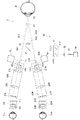
図1〜図5に、実施形態に係る眼科用顕微鏡システムの構成例を示す。図1〜図3、図5は、眼科用顕微鏡システムの光学系の構成例を示す。図1は後眼部を観察するときの光学系を示し、図2は前眼部を観察するときの光学系を示す。図4は、処理系の構成を示す。
[Constitution]
1 to 5 show a configuration example of an ophthalmic microscope system according to an embodiment. 1 to 3 and FIG. 5 show configuration examples of optical systems of an ophthalmic microscope system. FIG. 1 shows an optical system for observing the posterior eye part, and FIG. 2 shows an optical system for observing the anterior eye part. FIG. 4 shows the configuration of the processing system.
眼科用顕微鏡システム1は、照明系10(10L、10R)と、受光系20(20L、20R)と、接眼系30(30L、30R)と、照射系40と、OCT系60とを備える。後眼部(網膜等)を観察するときには、被検眼Eの直前に前置レンズ90が配置される。なお、図1に示すような非接触の前置レンズ90の代わりにコンタクトレンズ等を用いることが可能である。また、隅角を観察するときにはコンタクトミラー(三面鏡等)等を用いることができる。
The
(照明系10)
照明系10は、被検眼Eに照明光を照射する。図示は省略するが、照明系10は、照明光を発する光源や、変更可能な絞り値に応じて照明野を規定する絞りや、レンズ系などを含む。照明系10は、後述の制御部100の制御の下で、被検眼Eに照射される照明光の光量及び強度の少なくとも一方を変更可能である。なお、光の「強度」は単位面積における単位時間当たりの光量であり、「光量」は「強度」を時間積分することにより得られる物理量である。したがって、以下の実施形態では、特に言及しない限り「光量」と「強度」を同一視するものとする。
(Lighting system 10)
The
たとえば、照明光を発する光源は、制御部100からの制御信号により指定された制御量(電圧値、電流値など)に応じた光量で照明光を発する。それにより、制御部100は、光源に対して制御を行うことにより照明光の光量を変更することが可能である。また、制御部100は、光源に対して設定された制御量(電圧値、電流値など)を取得し、取得された制御量に対応した照明光の光量を検出することが可能である。たとえば、制御部100には、制御量と制御量に対応した照明光の光量とを対応付けた制御テーブルが予め記憶されている。制御部100は、この制御テーブルを参照することにより、取得された制御量に対応した照明光の光量を特定する。或いは、照明系10は、光源により発せられた照明光の光量を検出する照明光量検出部を含んでもよい。この場合、制御部100は、照明光量検出部による検出結果に基づいて照明光の光量を検出することが可能である。
For example, a light source that emits illumination light emits illumination light with a light amount corresponding to a control amount (voltage value, current value, etc.) specified by a control signal from the
また、制御部100からの制御信号により絞り値を指定することにより、被検眼Eに照射される照明光の光量を変更することが可能である。また、照明系10は、光源の向きや受光系20の光軸に対する後述のビームスプリッタ11L(11R)の角度を変更することにより、被検眼Eに対する照明光の照射角度を変更可能であってよい。制御部100からの制御信号に基づいて照明光の照射角度を変更することにより、被検眼Eに照射される照明光の光量を変更することが可能である。
In addition, by specifying an aperture value by a control signal from the
照明系10は、照明光の光量を低下させるND(Neutral Density)フィルタを含んでもよい。NDフィルタは、照明光の光路に挿脱可能な減光フィルタである。この場合、照明系10は、照明光の光路にNDフィルタを挿入したり、当該光路からNDフィルタを退避したりするための図示しない移動機構を含む。移動機構は、制御部100から制御信号を受け、当該制御信号に基づいて、照明光の光路にNDフィルタを挿入したり当該光路からNDフィルタを退避したりする。それにより、被検眼Eに照射される照明光の光量を変更することが可能である。照明光路の任意の位置でNDフィルタを挿脱させてよい。
The
照明系10の構成は、従来の眼科装置(たとえばスリットランプ顕微鏡、眼底カメラ、レフラクトメータ等)と同様であってよい。
The configuration of the
本実施形態の照明系10L及び10Rは、それぞれ受光系20L及び20Rと同軸に構成されている。具体的には、観察者の左眼E0Lに提示される像を取得するための左受光系20Lには、たとえばハーフミラーからなるビームスプリッタ11Lが斜設されている。ビームスプリッタ11Lは、左受光系20Lの光路に左照明系10Lの光路を同軸に結合している。左照明系10Lから出力された照明光は、ビームスプリッタ11Lにより反射され、左受光系20Lと同軸で被検眼Eを照明する。同様に、観察者の右眼E0Rに提示される像を取得するための右受光系20Rには、右受光系20Rの光路に右照明系10Rの光路を結合するビームスプリッタ11Rが斜設されている。ビームスプリッタ11Rは、右受光系20Rの光路に右照明系10Rの光路を同軸に結合している。右照明系10Rから出力された照明光は、ビームスプリッタ11Rにより反射され、右受光系20Rと同軸で被検眼Eを照明する。
The
受光系20L(20R)の光軸に対する照明光の位置を変更可能に構成することができる。この構成は、たとえば、従来の眼科手術用顕微鏡と同様に、ビームスプリッタ11L(11R)に対する照明光の照射位置を変更するための手段を設けることにより実現される。
The position of the illumination light with respect to the optical axis of the
本例では、対物レンズ21L(21R)と被検眼Eとの間にビームスプリッタ11L(11R)が配置されているが、照明光の光路が受光系20L(20R)に結合される位置は、受光系20L(20R)の任意の位置でよい。
In this example, the
(受光系20)
本実施形態では、左右一対の受光系20L及び20Rが設けられている。左受光系20Lは、観察者の左眼E0Lに提示される像を取得するための構成を有し、右受光系20Rは、右眼E0Rに提示される像を取得するための構成を有する。左受光系20Lと右受光系20Rは同じ構成を備える。左受光系20L(右受光系20R)は、対物レンズ21L(21R)と、結像レンズ22L(22R)と、撮像素子23L(23R)とを含む。
(Light receiving system 20)
In the present embodiment, a pair of left and right
なお、結像レンズ22L(22R)が設けられていない構成を適用することも可能である。本実施形態のように結像レンズ22L(22R)が設けられている場合、対物レンズ21L(21R)と結像レンズ22L(22R)との間をアフォーカルな光路(平行光路)とすることができる。それにより、フィルタ等の光学素子を配置することや、光路結合部材を配置して他の光学系からの光路を結合することが容易になる(すなわち、光学的構成の自由度や拡張性が向上される)。
A configuration in which the
符号AL1は、左受光系20Lの対物レンズ21Lの光軸(対物光軸)を示し、符号AR1は、右受光系20Rの対物レンズ21Rの光軸(対物光軸)を示す。撮像素子23L(23R)は、たとえばCCDイメージセンサやCMOSイメージセンサ等のエリアセンサである。
Symbol AL1 indicates the optical axis (objective optical axis) of the
以上は、被検眼Eの後眼部(眼底)を観察するときの受光系20の構成である(図1)。一方、前眼部を観察するときには、図2に示すように、対物レンズ21L(21R)に対して被検眼E側の位置に、フォーカスレンズ24L(24R)とウェッジプリズム25L(25R)とが配置される。本例のフォーカスレンズ24L(24R)は凹レンズであり、対物レンズ21L(21R)の焦点距離を延長するように作用する。ウェッジプリズム25L(25R)は、左受光系20L(右受光系20R)の光路(対物光軸AL1(AR1))を所定角度だけ外側に偏向する(符号AL2及びAR2で示す)。このように、フォーカスレンズ24L及びウェッジプリズム25Lが左受光系20Lに配置され、かつ、フォーカスレンズ24R及びウェッジプリズム25Rが右受光系20Rに配置される。それにより、後眼部観察用の焦点位置F1から前眼部観察用の焦点位置F2に切り替えられる。
The above is the configuration of the light receiving system 20 when observing the posterior segment (fundus) of the eye E (FIG. 1). On the other hand, when observing the anterior segment, as shown in FIG. 2, the
フォーカスレンズとして凸レンズを用いることが可能である。その場合、フォーカスレンズは、後眼部観察時に光路に配置され、前眼部観察時に光路から退避される。フォーカスレンズの挿入/退避によって焦点距離を切り替える代わりに、たとえば光軸方向に移動可能なフォーカスレンズを設けることにより焦点距離を連続的又は段階的に変更できるように構成することが可能である。 A convex lens can be used as the focus lens. In this case, the focus lens is disposed in the optical path when observing the posterior eye part, and is retracted from the optical path when observing the anterior eye part. Instead of switching the focal length by inserting / retracting the focus lens, for example, by providing a focus lens that can move in the optical axis direction, the focal length can be changed continuously or stepwise.
図2に示す例では、ウェッジプリズム25L(25R)の基底方向は外側である(つまりベースアウト配置である)が、ベースイン配置のウェッジプリズムを用いることができる。その場合、ウェッジプリズムは、後眼部観察時に光路に配置され、前眼部観察時に光路から退避される。ウェッジプリズムの挿入/退避によって光路の方向を切り替える代わりに、プリズム量(及びプリズム方向)が可変なプリズムを設けることにより光路の向きを連続的又は段階的に変更できるように構成することが可能である。
In the example shown in FIG. 2, the
(接眼系30)
本実施形態では、左右一対の接眼系30L及び30Rが設けられている。左接眼系30Lは、左受光系20Lにより取得された被検眼Eの像を観察者の左眼E0Lに提示するための構成を有し、右接眼系30Rは、右受光系20Rにより取得された被検眼Eの像を右眼E0Rに提示するための構成を有する。左接眼系30Lと右接眼系30Rは同じ構成を備える。左接眼系30L(右接眼系30R)は、表示部31L(31R)と、接眼レンズ系32L(32R)とを含む。
(Eyepiece 30)
In the present embodiment, a pair of left and
表示部31L(31R)は、たとえばLCD等のフラットパネルディスプレイである。表示部31L(31R)の表示面のサイズは、たとえば(対角線長)7インチ以下とされる。左右一対の接眼系30L及び30Rに設けられる表示デバイスの画面サイズは、観察者の眼幅(瞳孔間距離等)や、装置のサイズや、装置の設計(光学系や機構の配置等)などに制約を受ける。すなわち、このような制約条件と見掛け視野の広さはトレードオフの関係にある。このような観点から、表示部31L及び31Rの画面サイズの最大値は7インチ程度と考えられる。なお、接眼レンズ系32L及び32Rの構成や機構の配置を工夫することにより、7インチを超える画面サイズの表示部31L及び31Rを適用することができ、或いは、小サイズの表示部31L及び31Rを適用することができる。
左接眼系30Lと右接眼系30Rとの間隔を変更することが可能である。それにより、観察者の眼幅に応じて左接眼系30Lと右接眼系30Rとの間隔を調整することができる。また、左接眼系30Lと右接眼系30Rとの相対的向きを変更することが可能である。つまり、左接眼系30Lの光軸と右接眼系30Rの光軸とがなす角度を変更することが可能である。それにより、両眼E0L及びE0Rの輻輳を誘発することができ、観察者による立体視を支援することができる。
It is possible to change the interval between the
(照射系40)
照射系40は、前述した「他の眼科装置」としての機能を実現するための光を、受光系20の対物光軸(AL1及びAR1、並びにAL2及びAR2)と異なる方向から被検眼Eに照射する。本例の照射系40は、OCTのための光(測定光)を被検眼Eに照射する。
(Irradiation system 40)
The
照射系40は、光スキャナ41と、結像レンズ42と、偏向ミラー43と、OCT対物レンズ44とを含む。光スキャナ41には、OCT系60からの光が導かれる。結像レンズ42は、フォーカスレンズとしてOCT系60からの光の光路に沿って移動可能であってよい。この場合、図示しない移動機構が、後述の制御部100から制御信号を受け、当該制御信号により指定された移動方向に、指定された移動量だけ結像レンズ42を移動させる。
The
OCT系60からの光(測定光)は、光ファイバ51により導かれ、そのファイバ端面から出射する。このファイバ端面に臨む位置には、コリメートレンズ52が配置されている。コリメートレンズ52は、ファイバ端面から出射した測定光を平行光束にする。コリメートレンズ52により平行光束とされた測定光は、光スキャナ41に導かれる。なお、コリメートレンズ52は、フォーカスレンズ(或いはフォーカスレンズを構成するレンズ群の1つ)として測定光の光路に沿って移動可能であってよい。この場合、図示しない移動機構が、後述の制御部100からの制御信号を受け、当該制御信号により指定された移動方向に、指定された移動量だけコリメートレンズ52を移動させる。結像レンズ42及びコリメートレンズ52の双方が、移動機構により連動して又は独立に移動されてもよい。
Light (measurement light) from the
光スキャナ41は、2次元光スキャナであり、水平方向(x方向)へ光を偏向するxスキャナ41Hと、垂直方向(y方向)へ光を偏向するyスキャナ41Vとを含む。xスキャナ41H及びyスキャナ41Vは、それぞれ任意の形態の光スキャナであってよく、たとえばガルバノミラーが使用される。光スキャナ41は、たとえば、コリメートレンズ52の射出瞳位置又はその近傍位置に配置される。更に、光スキャナ41は、たとえば、結像レンズ42の入射瞳位置又はその近傍位置に配置される。
The
本例のように2つの1次元光スキャナを組み合わせて2次元光スキャナを構成する場合、2つの1次元光スキャナは所定距離(たとえば10mm程度)だけ離れて配置される。それにより、たとえば、いずれかの1次元光スキャナを上記射出瞳位置及び/又は上記入射瞳位置に配置することができる。 When a two-dimensional optical scanner is configured by combining two one-dimensional optical scanners as in this example, the two one-dimensional optical scanners are arranged apart from each other by a predetermined distance (for example, about 10 mm). Thereby, for example, any one-dimensional optical scanner can be arranged at the exit pupil position and / or the entrance pupil position.
結像レンズ42は、光スキャナ41を通過した平行光束(測定光)を一旦結像させる。結像レンズ42を通過した光は、偏向ミラー43によりOCT対物レンズ44に向けて反射される。OCT対物レンズ44を通過した光は、被検眼Eに照射される。
The
照射系40により導かれてきた光が受光系20の対物光軸(AL1及びAR1、並びにAL2及びAR2)と異なる方向から被検眼Eに照射されるように、偏向ミラー43の位置は予め決定されている。本例では、互いの対物光軸が非平行に配置された左受光系20Lと右受光系20Rとの間の位置に偏向ミラー43が配置されている。
The position of the
(OCT系60)
OCT系60は、OCTを実行するための干渉光学系を含む。OCT系60の構成の例を図3に示す。図3に示す光学系は、スウェプトソースOCTの例であり、波長走査型(波長掃引型)光源からの光を測定光と参照光とに分割し、被検眼Eからの測定光の戻り光と参照光路を経由した参照光とを干渉させて干渉光を生成し、この干渉光を検出する。干渉光学系による干渉光の検出結果(検出信号)は、干渉光のスペクトルを示す信号であり、制御部100に送られる。
(OCT system 60)
The
光源ユニット61は、一般的なスウェプトソースタイプのOCT装置と同様に、出射光の波長を走査(掃引)可能な波長走査型(波長掃引型)光源を含む。光源ユニット61は、人眼では視認できない近赤外の波長帯において、出力波長を時間的に変化させる。
The
OCT系60は、光源ユニット61から出力された光L0又は後述の測定光LSの光量を変更可能である。たとえば、光源ユニット61は、制御部100からの制御信号により指定された制御量(電圧値、電流値など)に応じた光量で光L0を出力する。それにより、制御部100は、光源ユニット61に対して制御を行うことにより光L0の光量を変更することが可能である。また、光源ユニット61と後述の偏波コントローラ63との間にアッテネータを設け、制御部100からの制御の下で、光源ユニット61から出力された光L0の光量が変更されてもよい。
The
被検眼Eに導かれる測定光LSの光路にアッテネータを設け、制御部100からの制御の下で測定光LSの光量が変更されてもよい。この場合、参照光LRの光路にもアッテネータを設け、制御部100からの制御の下で測定光LSの光量の変化分に応じて参照光LRの光量が変更されてもよい。図3に示す構成では、後述のように測定光LSの戻り光が同一経路で戻るため、測定光LSの戻り光も当該アッテネータにより光量が変更される。したがって、参照光LRの光量の変化分(減衰量)をRAとし、測定光LSの光量の変化分(減衰量)をSAとしたとき、RA>SAとなるように参照光LRの光量が変更されてよい。
An attenuator may be provided in the optical path of the measurement light LS guided to the eye E, and the light amount of the measurement light LS may be changed under the control of the
光源ユニット61から出力された光L0は、光ファイバ62により偏波コントローラ63に導かれてその偏光状態が調整される。光源ユニット61と偏波コントローラ63との間にアッテネータが設けられている場合、光L0は光ファイバによりアッテネータに導かれてその光量が調整される。光量が調整された光L0は、光ファイバ62により偏波コントローラ63に導かれる。偏波コントローラ63により偏光状態が調整された光L0は、光ファイバ64によりファイバカプラ65に導かれて測定光LSと参照光LRとに分割される。
The light L0 output from the
参照光LRは、光ファイバ66Aによりコリメータ67に導かれて平行光束に変換され、光路長補正部材68及び分散補償部材69を経由し、コーナーキューブ70に導かれる。光路長補正部材68は、参照光LRの光路長(光学距離)と測定光LSの光路長とを合わせるための遅延手段として作用する。分散補償部材69は、参照光LRと測定光LSとの間の分散特性を合わせるための分散補償手段として作用する。
The reference light LR is guided to the
コーナーキューブ70は、参照光LRの進行方向を逆方向に折り返す。コーナーキューブ70は、参照光LRの入射光路及び出射光路に沿う方向に移動可能とされ、それにより参照光LRの光路の長さが変更される。なお、測定光LSの光路の長さを変更するための手段と、参照光LRの光路の長さを変更するための手段のうちのいずれか一方が設けられていればよい。
The
コーナーキューブ70を経由した参照光LRは、分散補償部材69及び光路長補正部材68を経由し、コリメータ71によって平行光束から集束光束に変換されて光ファイバ72に入射し、偏波コントローラ73に導かれて参照光LRの偏光状態が調整される。更に、参照光LRは、光ファイバ74によりアッテネータ75に導かれて、制御部100の制御の下で光量が調整される。光量が調整された参照光LRは、光ファイバ76によりファイバカプラ77に導かれる。
The reference light LR that has passed through the
一方、ファイバカプラ65により生成された測定光LSは、光ファイバ51により導かれてファイバ端面から出射され、コリメートレンズ52により平行光束とされる。平行光束にされた測定光LSは、光スキャナ41、結像レンズ42、偏向ミラー43及びOCT対物レンズ44を経由して被検眼Eに照射される。測定光LSは、被検眼Eの様々な深さ位置において反射・散乱される。被検眼Eからの測定光LSの戻り光は、反射光や後方散乱光を含み、往路と同じ経路を逆向きに進行してファイバカプラ65に導かれ、光ファイバ66Bを経由してファイバカプラ77に到達する。
On the other hand, the measurement light LS generated by the
ファイバカプラ77は、光ファイバ66Bを介して入射された測定光LSと、光ファイバ76を介して入射された参照光LRとを合成して(干渉させて)干渉光を生成する。ファイバカプラ77は、所定の分岐比(たとえば1:1)でこの干渉光を分割することにより、一対の干渉光LCを生成する。ファイバカプラ77から出射した一対の干渉光LCは、それぞれ光ファイバ78A及び78Bにより検出器79に導かれる。
The
検出器79は、たとえば一対の干渉光LCをそれぞれ検出する一対のフォトディテクタを含み、これらによる検出結果の差分を出力するバランスドフォトダイオード(Balanced Photo Diode)である。検出器79は、その検出結果(検出信号)を制御部100に送る。
The
この実施形態では、事前に指定された動作モードに応じて照明光と測定光LSのいずれかの光量を制限することにより、照明光と測定光LSの合成光量が既定値以下となるように被検眼Eに照明光と測定光LSを照射する。合成光量は、被検眼Eに同時に照射される照明光の光量と測定光LSの光量との和である。既定値は、たとえば、光ハザードからの保護に関する規格において規定された値に基づいて予め決められている。OCT系60は、上記の合成光量をモニタするために、光源ユニット61からの光L0又は測定光LSの光量を検出する光量検出部80を含んでもよい。光量検出部80により光L0又は測定光LSの光量を検出することで、制御部100は、測定光LSの光量の制限量を特定することができる。また、制御部100は、たとえば、照明系10の光源に対して設定された制御量などを取得することにより、照明光の光量を特定することができる。それにより、制御部100は、照明光及び測定光LSの光量をモニタしつつ、合成光量が既定値以下となるように照明光又は測定光LSのいずれかの光量を制限することができる。
In this embodiment, the amount of light of the illumination light and the measurement light LS is limited according to the operation mode designated in advance, so that the combined light amount of the illumination light and the measurement light LS is less than a predetermined value. The optometry E is irradiated with illumination light and measurement light LS. The combined light amount is the sum of the light amount of illumination light and the light amount of the measurement light LS that are simultaneously irradiated to the eye E. The predetermined value is determined in advance based on, for example, a value defined in a standard related to protection from optical hazard. The
本例ではスウェプトソースOCTが適用されているが、他のタイプのOCT、たとえばスペクトラルドメインOCTを適用することが可能である。 In this example, swept source OCT is applied, but other types of OCT, such as spectral domain OCT, can be applied.
(制御部100)
制御部100は、眼科用顕微鏡システム1の各部の制御を実行する(図4参照)。照明系10の制御の例として次のものがある:光源の点灯、消灯、光量調整、光量検出;絞り10aの絞り値の変更;NDフィルタ10bの挿脱制御;スリット照明が可能な場合にはスリット幅の調整。光量調整は、光源に対して制御量を設定することにより行われる照明光の光量調整である。光量検出は、光源に対して設定された制御量を取得することにより行われる照明光の光量検出である。撮像素子23の制御として、露光調整やゲイン調整や撮影レート調整などがある。
(Control unit 100)
The
制御部100は、各種の情報を表示部31に表示させる。たとえば、制御部100は、撮像素子23Lにより取得された画像(又はそれを処理して得られた画像)を表示部31Lに表示させ、かつ、撮像素子23Rにより取得された画像(又はそれを処理して得られた画像)を表示部31Rに表示させる。
The
光スキャナ41の制御として、たとえば、予め設定されたOCTスキャンパターンに応じた複数の位置に測定光LSが照射されるように、測定光LSを順次に偏向する。
As control of the
OCT系60に含まれる制御対象としては、光源ユニット61、アッテネータ62a、偏波コントローラ63、コーナーキューブ70、偏波コントローラ73、アッテネータ75、検出器79、光量検出部80などがある。
Control targets included in the
アッテネータ62aは、前述のように光源ユニット61と偏波コントローラ63との間に設けられており、光源ユニット61からの光L0の光量を調整する。アッテネータ62aの制御として、制御信号により指定された減衰量だけ光L0の光量を減衰させる。
As described above, the
光量検出部80は、光源ユニット61からの光L0又は測定光LSの光量を検出する。たとえば、光L0の光路又は測定光LSの光路に光路分離部材が配置される。光路分離部材は、光L0の光路又は測定光LSの光路からモニタ用光路を分離する。光量検出部80は、光路分離部材により分離されたモニタ用光路に配置される。このような光量検出部80は、たとえば図3に示す構成と同様に、ファイバカプラと検出器とを含む。光量検出部80の検出信号は、制御部100に送られる。
The light
更に、制御部100は、各種の機構を制御する。そのような機構としては、ステレオ角変更部20A、合焦部24A、光路偏向部25A、間隔変更部30A、及び向き変更部30Bが設けられている。
Furthermore, the
ステレオ角変更部20Aは、左受光系20Lと右受光系20Rとを相対的に回転移動する。すなわち、ステレオ角変更部20Aは、互いの対物光軸(たとえばAL1とAR1)がなす角度を変更するように左受光系20Lと右受光系20Rとを相対移動させる。この相対移動は、たとえば、左受光系20Lと右受光系20Rとを反対の回転方向に同じ角度だけ移動させるものである。この移動態様においては、互いの対物光軸(たとえばAL1とAR1)がなす角の二等分線の向きは一定である。一方、当該二等分線の向きが変化するように上記相対移動を行うことも可能である。
The stereo
図2に示す状態からステレオ角が拡大された状態の例を図5に示す。なお、ステレオ角は、左受光系20Lの対物光軸AL1と右受光系20Rの対物光軸AR1とがなす角として定義されてもよいし、左受光系20Lの対物光軸AL2と右受光系20Rの対物光軸AR2とがなす角として定義されてもよい。ステレオ角変更部20Aによりステレオ角が変更されても、左右の接眼系30L及び30Rの相対位置(間隔、相対的向き)は変化しない。また、ステレオ角の変化に対応して、被検眼Eに対する左右の受光系20L及び20Rの距離を調整したり、左右の受光系20L及び20Rの焦点距離を変更したりすることにより、焦点位置が移動しないように制御を行うことができる。
An example of a state in which the stereo angle is enlarged from the state shown in FIG. 2 is shown in FIG. The stereo angle may be defined as an angle formed by the objective optical axis AL1 of the left
合焦部24Aは、左右のフォーカスレンズ24L及び24Rを光路に対して挿入/退避させる。合焦部24Aは、左右のフォーカスレンズ24L及び24Rを同時に挿入/退避させるように構成されていてよい。他の例において、合焦部24Aは、左右のフォーカスレンズ24L及び24Rを(同時に)光軸方向に移動させることによって焦点位置を変更するように構成されてよい。或いは、合焦部24Aは、左右のフォーカスレンズ24L及び24Rの屈折力を(同時に)変更することによって焦点距離を変更するように構成されてよい。
The focusing
光路偏向部25Aは、左右のウェッジプリズム25L及び25Rを光路に対して挿入/退避させる。光路偏向部25Aは、左右のウェッジプリズム25L及び25Rを同時に挿入/退避させるように構成されていてよい。他の例において、光路偏向部25Aは、左右のウェッジプリズム25L及び25Rのプリズム量(及びプリズム方向)を(同時に)変更することによって左右の受光系20L及び20Rの光路の向きを変更するように構成されてよい。
The optical
間隔変更部30Aは、左右の接眼系30L及び30Rの間隔を変更する。間隔変更部30Aは、互いの光軸の相対的向きを変化させずに左右の接眼系30L及び30Rを相対的に移動するように構成されてよい。
The
向き変更部30Bは、左右の接眼系30L及び30Rの相対的向きを変更する。向き変更部30Bは、互いの光軸がなす角度を変更するように左接眼系30Lと右接眼系30Rとを相対移動させる。この相対移動は、たとえば、左接眼系30Lと右接眼系30Rとを反対の回転方向に同じ角度だけ移動させるものである。この移動態様においては、互いの光軸がなす角の二等分線の向きは一定である。一方、当該二等分線の向きが変化するように上記相対移動を行うことも可能である。
The
制御部100は、前述のように照明光の光量と測定光LSの光量とを特定することが可能である。制御部100は、特定された照明光の光量と測定光LSの光量とに基づいて、照明光と測定光LSとの合成光量が既定値以下となるように測定光LSの光量を制限する第1光量制御を実行することが可能である。制御部100は、光源ユニット61及びアッテネータ62aの少なくとも一方を制御することにより測定光LSの光量を制限することができる。また、制御部100は、特定された照明光の光量と測定光LSの光量とに基づいて、照明光と測定光LSとの合成光量が既定値以下となるように照明光の光量を制限する第2光量制御を実行することが可能である。制御部100は、照明系10の光源、被検眼Eに対する照明光の照射角度、絞り10aの絞り値及びNDフィルタ10bの少なくとも1つを制御することにより照明光の光量を制限することができる。
As described above, the
制御部100は、動作モードに応じて第1光量制御又は第2光量制御を実行する。この実施形態では、動作モードには、観察優先モード(照明光優先モード)とOCT優先モード(OCT光優先モード)とがある。観察優先モードは、既定値以下の合成光量となるように測定光LSの光量を制限することにより、照明光の光量を確保しつつ照明光と測定光LSとを被検眼Eに同時に照射するための動作モードである。観察優先モードでは、光ハザードからの保護を図りつつ、OCT画像の画質よりも照明光の戻り光に基づく観察像の画質を向上させることが可能になる。OCT優先モードは、既定値以下の合成光量となるように照明光の光量を制限することにより、測定光LSの光量を確保しつつ照明光と測定光LSとを被検眼Eに同時に照射するための動作モードである。OCT優先モードでは、光ハザードからの保護を図りつつ、観察像の画質よりもOCT画像の画質を向上させることが可能になる。このとき、制御部100は、光量検出部80による検出結果に基づいて第1光量制御及び第2光量制御の少なくとも一方を行うことが可能である。
The
なお、制御部100は、被検眼Eに対する測定光LS又は照明光の照射時間を低減させることにより測定光LS又は照明光の光量を制限してもよい。それにより、測定光LS又は照明光の強度を制限することなく、測定光LS又は照明光の光量を制限することが可能になり、第1光量制御又は第2光量制御を簡素化することができる。
In addition, the
また、制御部100は、観察優先モードのときに干渉光LCの検出感度が上がるように検出器79を制御してもよい。検出器79の制御には、検出器79により得られた検出信号に対するゲインを上げたり、検出信号の取得タイミングを長くしたりすることなどがある。それにより、観察優先モードにおいて測定光LSの光量が制限された場合であっても、OCT画像の画質の劣化を抑えることができるようになる。
Further, the
(データ処理部200)
データ処理部200は、各種のデータ処理を実行する。このデータ処理には、画像を形成する処理や、画像を加工する処理などが含まれる。また、データ処理部200は、画像や検査結果や測定結果の解析処理や、被検者に関する情報(電子カルテ情報等)に関する処理を実行可能であってよい。データ処理部200には、変倍処理部210と、OCT画像形成部220とが含まれる。
(Data processing unit 200)
The
変倍処理部210は、撮像素子23により取得された画像を拡大する。この処理は、いわゆるデジタルズーム処理であり、撮像素子23により取得された画像の一部を切り取る処理と、その部分の拡大画像を作成する処理とを含む。画像の切り取り範囲は、観察者により又は制御部100により設定される。変倍処理部210は、左受光系20Lの撮像素子23Lにより取得された画像(左画像)と、右受光系20Rの撮像素子23Rにより取得された画像(右画像)とに対して、同じ処理を施す。それにより、観察者の左眼E0Lと右眼E0Rとに同じ倍率の画像が提示される。
The scaling
なお、このようなデジタルズーム機能に加えて、又はそれの代わりに、いわゆる光学ズーム機能を設けることが可能である。光学ズーム機能は、左右の受光系20L及び20Rのそれぞれに変倍レンズ(変倍レンズ系)を設けることにより実現される。具体例として、変倍レンズを(選択的に)光路に対して挿入/退避する構成や、変倍レンズを光軸方向に移動させる構成がある。光学ズーム機能に関する制御は制御部100によって実行される。
In addition to or instead of such a digital zoom function, a so-called optical zoom function can be provided. The optical zoom function is realized by providing a variable magnification lens (variable lens system) in each of the left and right
OCT画像形成部220は、OCT系60の検出器79により得られる干渉光LCの検出結果に基づいて、被検眼Eの画像を形成する。制御部100は、検出器79から順次に出力される検出信号をOCT画像形成部220に送る。OCT画像形成部220は、たとえば一連の波長走査毎に(Aライン毎に)、検出器79により得られた検出結果に基づくスペクトル分布にフーリエ変換等を施すことにより、各Aラインにおける反射強度プロファイルを形成する。更に、OCT画像形成部220は、各Aラインプロファイルを画像化することにより画像データを形成する。それにより、Bスキャン像(断面像)やボリュームデータ(3次元画像データ)が得られる。
The OCT
データ処理部200は、OCT画像形成部220により形成された画像(OCT画像)を解析する機能を備えていてよい。この解析機能としては、網膜厚解析や、正常眼との比較解析などがある。このような解析機能は、公知のアプリケーションを用いて実行される。また、データ処理部200は、受光系20により取得された画像を解析する機能を備えていてよい。また、データ処理部200は、受光系20により取得された画像の解析とOCT画像の解析とを組み合わせた解析機能を備えていてもよい。
The
(ユーザインターフェイス300)
ユーザインターフェイス(UI)300は、観察者等と眼科用顕微鏡システム1との間で情報のやりとりを行うための機能を備える。ユーザインターフェイス300は、表示デバイスと操作デバイス(入力デバイス)とを含む。この実施形態では、ユーザインターフェイス300は、たとえば、眼科用顕微鏡システム1の動作モードの指定や、OCT測定の実行の指示などに用いられる。表示デバイスは、表示部31を含んでよく、それ以外の表示デバイスを含んでもよい。操作デバイスは、各種のハードウェアキー及び/又はソフトウェアキーを含む。操作デバイスの少なくとも一部と表示デバイスの少なくとも一部とを一体的に構成することが可能である。タッチパネルディスプレイはその一例である。
(User interface 300)
The user interface (UI) 300 has a function for exchanging information between an observer or the like and the
(通信部400)
通信部400は、他の装置に情報を送信する処理と、他の装置から送られた情報を受信する処理とを行う。通信部400は、既定のネットワーク(LAN、インターネット等)に準拠した通信デバイスを含んでいてよい。たとえば、通信部400は、医療機関内に設けられたLANを介して、電子カルテデータベースや医用画像データベースから情報を取得する。また、外部モニタが設けられている場合、通信部400は、眼科用顕微鏡システム1により取得される画像(受光系20により取得される画像、OCT画像等)を、実質的にリアルタイムで外部モニタに送信することができる。
(Communication unit 400)
The
OCT系60は、実施形態に係る「干渉光学系」の一例である。光源ユニット61は、実施形態に係る「OCT光源」の一例である。ユーザインターフェイス300は、実施形態に係る「指定部」の一例である。NDフィルタ10bは、実施形態に係る「フィルタ」の一例である。
The
[動作例]
図6に、実施形態に係る眼科用顕微鏡システム1の動作例のフロー図を示す。図6は、眼科用顕微鏡システム1の動作モードを切り換える場合の動作例を表す。
[Operation example]
FIG. 6 shows a flowchart of an operation example of the
眼科用顕微鏡システム1の動作モードは、制御部100により自動で指定される場合と、ユーザインターフェイス300を用いて手動で指定される場合とがある。制御部100は、眼科用顕微鏡システム1の動作モードを任意のタイミングで当該指定された動作モードに切り換えることが可能である。
The operation mode of the
(S1)
眼科用顕微鏡システム1の電源が投入されたとき、制御部100は、眼科用顕微鏡システム1の動作モードを観察優先モードに設定する。
(S1)
When the power of the
(S2)
制御部100は、OCT測定を実行するか否かを判定する。たとえば、OCT測定を実行するか否かは、ユーザインターフェイス300を用いてユーザにより指示される。制御部100は、ユーザインターフェイス300に対するユーザの操作内容に基づいて、OCT測定を実行するか否かを判定することが可能である。OCT測定を実行すると判定されたとき(S2:Y)、眼科用顕微鏡システム1の動作はS3に移行する。OCT測定を実行すると判定されなかったとき(S2:N)、眼科用顕微鏡システム1の動作はS4に移行する。
(S2)
The
(S3)
OCT測定を実行すると判定されたとき(S2:Y)、制御部100は、眼科用顕微鏡システム1の動作モードを観察優先モードからOCT優先モードに切り換える。OCT優先モードでは、前述のように、特定された照明光の光量と測定光LSの光量とに基づいて、既定値以下の合成光量となるように測定光LSの光量を確保しつつ照明光の光量が制限される。眼科用顕微鏡システム1の動作はS8に移行する。
(S3)
When it is determined that the OCT measurement is to be executed (S2: Y), the
(S4)
OCT測定を実行すると判定されなかったとき(S2:N)、制御部100は、動作モードを切り換えるか否かを判定する。たとえば、動作モードを切り換えるか否かは、ユーザインターフェイス300を用いてユーザにより指示される。制御部100は、ユーザインターフェイス300に対するユーザの操作内容に基づいて、動作モードを切り換えるか否かを判定することが可能である。動作モードを切り換えると判定されたとき(S4:Y)、眼科用顕微鏡システム1の動作はS5に移行する。動作モードを切り換えると判定されなかったとき(S4:N)、眼科用顕微鏡システム1の動作はS8に移行する。
(S4)
When it is not determined to execute the OCT measurement (S2: N), the
(S5)
動作モードを切り換えると判定されたとき(S4:Y)、制御部100は、観察優先モードに切り換えるか否かを判定する。たとえば、制御部100は、ユーザインターフェイス300に対するユーザの操作内容に基づいて、観察優先モードに切り換えるか否かを判定することが可能である。観察優先モードに切り換えると判定されたとき(S5:Y)、眼科用顕微鏡システム1の動作はS6に移行する。観察優先モードに切り換えると判定されなかったとき(S5:N)、眼科用顕微鏡システム1の動作はS7に移行する。
(S5)
When it is determined that the operation mode is to be switched (S4: Y), the
(S6)
観察優先モードに切り換えると判定されたとき(S5:Y)、制御部100は、切り換え後の動作モードを観察優先モードに設定する。切り換え前の動作モードが観察優先モードのとき、制御部100はそのまま動作モードを観察優先モードとして継続させる。切り換え前の動作モードがOCT優先モードのとき、制御部100は、動作モードをOCT優先モードから観察優先モードに切り換える。観察優先モードでは、前述のように、特定された照明光の光量と測定光LSの光量とに基づいて、既定値以下の合成光量となるように照明光の光量を確保しつつ測定光LSの光量が制限される。それにより、手術中にOCT画像を取得する場合であっても、光ハザードからの保護を図りつつ、高画質の観察像を取得することが可能になる。眼科用顕微鏡システム1の動作はS8に移行する。
(S6)
When it is determined to switch to the observation priority mode (S5: Y), the
(S7)
観察優先モードに切り換えると判定されなかったとき(S5:N)、制御部100は、切り換え後の動作モードをOCT優先モードに設定する。切り換え前の動作モードがOCT優先モードのとき、制御部100はそのまま動作モードをOCT優先モードとして継続させる。切り換え前の動作モードが観察優先モードのとき、制御部100は、動作モードを観察優先モードからOCT優先モードに切り換える。それにより、手術中にOCT画像を取得する場合であっても、光ハザードからの保護を図りつつ、一時的に高画質のOCT画像を取得することが可能になる。眼科用顕微鏡システム1の動作はS8に移行する。
(S7)
When it is not determined to switch to the observation priority mode (S5: N), the
(S8)
制御部100は、眼科用顕微鏡システム1の動作を終了するか否かを判定する。たとえば、動作の終了は、ユーザインターフェイス300を用いてユーザにより指示される。制御部100は、ユーザインターフェイス300に対するユーザの操作内容に基づいて、動作を終了するか否かを判定することが可能である。動作を終了すると判定されなかったとき(S8:N)、眼科用顕微鏡システム1の動作はS4に移行する。動作を終了すると判定されたとき(S8:Y)、眼科用顕微鏡システム1の動作は終了する(エンド)。
(S8)
The
[効果]
実施形態の眼科用顕微鏡システムの効果について説明する。
[effect]
The effect of the ophthalmic microscope system of the embodiment will be described.
実施形態に係る眼科用顕微鏡システム(眼科用顕微鏡システム1)は、照明系(照明系10)と、受光系(受光系20)と、干渉光学系(OCT系60)と、指定部(ユーザインターフェイス300)と、制御部(制御部100)とを含む。照明系は、被検眼(被検眼E)に照明光を照射する。受光系は、被検眼に照射された照明光の戻り光を撮像素子(撮像素子23)又は接眼レンズ系に導く。干渉光学系は、OCT光源(光源ユニット61)からの光(光L0)を測定光(測定光LS)と参照光(参照光LR)とに分割し、被検眼に照射された測定光の戻り光と参照光との干渉光(干渉光LC)を検出する。指定部は、動作モードを指定するために用いられる。制御部は、指定部により観察優先モードが指定されたときに照明光と測定光の合成光量が既定値以下となるように測定光の光量を制限する第1光量制御を行う。制御部は、指定部によりOCT優先モードが指定されたときに合成光量が既定値以下となるように照明光の光量を制限する第2光量制御を行う。 An ophthalmic microscope system (ophthalmic microscope system 1) according to the embodiment includes an illumination system (illumination system 10), a light receiving system (light receiving system 20), an interference optical system (OCT system 60), and a designation unit (user interface). 300) and a control unit (control unit 100). The illumination system irradiates the eye to be examined (eye E to be examined) with illumination light. The light receiving system guides the return light of the illumination light applied to the eye to be examined to the imaging device (imaging device 23) or the eyepiece lens system. The interference optical system divides light (light L0) from the OCT light source (light source unit 61) into measurement light (measurement light LS) and reference light (reference light LR), and returns the measurement light irradiated to the eye to be examined. Interference light (interference light LC) between the light and the reference light is detected. The designation unit is used for designating an operation mode. The control unit performs first light amount control for limiting the light amount of the measurement light so that the combined light amount of the illumination light and the measurement light is equal to or less than a predetermined value when the observation priority mode is designated by the designation unit. The control unit performs second light amount control for limiting the amount of illumination light so that the combined light amount is equal to or less than a predetermined value when the OCT priority mode is specified by the specifying unit.
このような構成によれば、照明光と測定光との合成光量が既定値になるように動作モードに応じて照明光又は測定光の光量を制限するようにしたので、被検眼の安全性と動作モードに応じた画像の画質の向上とを両立させることができるようになる。それにより、干渉光学系を受光系に組み合わせた場合でも光ハザードからの保護を図りつつ、動作モードに対応した画像の画質の向上が可能になる。 According to such a configuration, the light amount of the illumination light or the measurement light is limited according to the operation mode so that the combined light amount of the illumination light and the measurement light becomes a predetermined value. It is possible to achieve both improvement in image quality according to the operation mode. Thereby, even when the interference optical system is combined with the light receiving system, the image quality corresponding to the operation mode can be improved while protecting from the light hazard.
また、実施形態に係る眼科用顕微鏡システムは、光量検出部(光量検出部80)を含んでもよい。光量検出部は、OCT光源からの光又は測定光の光量を検出する。制御部は、光量検出部による検出結果に基づいて第1光量制御及び第2光量制御の少なくとも一方を行う。 The ophthalmic microscope system according to the embodiment may include a light amount detection unit (light amount detection unit 80). The light quantity detection unit detects the light quantity of the light from the OCT light source or the measurement light. The control unit performs at least one of the first light amount control and the second light amount control based on the detection result by the light amount detection unit.
このような構成によれば、OCT光源からの光又は測定光の光量の検出結果に基づいて、合成光量が既定値以下となるように照明光又は測定光LSのいずれかの光量を制限することが可能になる。 According to such a configuration, based on the detection result of the light amount of the OCT light source or the measurement light, the light amount of the illumination light or the measurement light LS is limited so that the combined light amount is equal to or less than a predetermined value. Is possible.
また、実施形態に係る眼科用顕微鏡システムは、アッテネータ(アッテネータ62a)を含んでもよい。アッテネータは、OCT光源からの光又は測定光の光量を調整する。制御部は、OCT光源及びアッテネータの少なくとも一方を制御することにより測定光の光量を制限する。
The ophthalmic microscope system according to the embodiment may include an attenuator (
このような構成によれば、観察優先モードにおいて測定光の光量を、容易、かつ、高精度に制限することが可能になる。 According to such a configuration, it is possible to easily and accurately limit the amount of measurement light in the observation priority mode.
また、実施形態に係る眼科用顕微鏡システムでは、照明系は、被検眼に対する照明光の照射角度を変更可能であってよい。照明系は、絞り(絞り10a)と、フィルタ(NDフィルタ10b)とを含む。絞りは、絞り値が可変である。フィルタは、照明光の光路に挿脱可能である。制御部は、照明系の光源、照射角度、絞り値及びフィルタの少なくとも1つを制御することにより照明光の光量を制限する。
In the ophthalmic microscope system according to the embodiment, the illumination system may be able to change the irradiation angle of the illumination light with respect to the eye to be examined. The illumination system includes a stop (stop 10a) and a filter (
このような構成によれば、OCT優先モードにおいて照明光の光量を、容易、かつ、高精度に制限することが可能になる。 According to such a configuration, it is possible to easily and accurately limit the amount of illumination light in the OCT priority mode.
また、実施形態に係る眼科用顕微鏡システムでは、制御部は、被検眼に対する測定光又は照明光の照射時間を低減させることにより測定光又は照明光の光量を制限してもよい。 In the ophthalmic microscope system according to the embodiment, the control unit may limit the amount of the measurement light or the illumination light by reducing the irradiation time of the measurement light or the illumination light on the eye to be examined.
このような構成によれば、測定光又は照明光の強度を制限することなく、測定光又は照明光の光量を制限することが可能になり、第1光量制御又は第2光量制御を簡素化することができるようになる。 According to such a configuration, it becomes possible to limit the light amount of the measurement light or the illumination light without limiting the intensity of the measurement light or the illumination light, thereby simplifying the first light amount control or the second light amount control. Will be able to.
また、実施形態に係る眼科用顕微鏡システムでは、干渉光学系は、検出器(検出器79)を含んでもよい。検出器は、干渉光を検出する。制御部は、観察優先モードが指定されたときに干渉光の検出感度が上がるように検出器を制御する。 In the ophthalmic microscope system according to the embodiment, the interference optical system may include a detector (detector 79). The detector detects the interference light. The control unit controls the detector so that the detection sensitivity of the interference light increases when the observation priority mode is designated.
このような構成によれば、観察優先モードにおいて測定光の光量が制限された場合であっても、干渉光の検出結果に基づく画像の画質の劣化を抑えることができるようになる。 According to such a configuration, even when the amount of measurement light is limited in the observation priority mode, it is possible to suppress deterioration in image quality based on the detection result of interference light.
[変形例]
上記の実施形態は、本発明を実施するための例示に過ぎない。本発明を実施しようとする者は、本発明の要旨の範囲内において任意の変形、省略、追加、置換等を施すことが可能である。以下、上記の実施形態における図面を適宜に参照する。
[Modification]
The above embodiments are merely examples for carrying out the present invention. A person who intends to implement the present invention can make arbitrary modifications, omissions, additions, substitutions and the like within the scope of the present invention. Hereinafter, the drawings in the above embodiments will be referred to as appropriate.
(変形例1)
上記の実施形態において、フォーカスレンズ24L及び24R並びにウェッジプリズム25L及び25Rは、眼底観察時には光路から退避され、前眼部観察時には光路に挿入される。このような動作を自動化することが可能である。実施形態では、被検眼の観察部位を変更するための補助光学部材が使用される。たとえば、眼底観察時には光路に前置レンズ90が配置され、前眼部観察時には光路から退避される。
(Modification 1)
In the above embodiment, the
本変形例の眼科用顕微鏡システムは、補助光学部材の状態(つまり観察部位の選択)に応じてフォーカスレンズ24L及び24Rの状態を変更する。つまり、制御部100は、補助光学部材による観察部位の変更に応じて、フォーカスレンズ24L及び24Rを連係動作するための第2機構を制御する。同様に、制御部100は、補助光学部材による観察部位の変更に応じて、ウェッジプリズム25L及び25Rを連係動作させるための第3機構を制御する。
The ophthalmic microscope system according to the present modification changes the states of the
具体例を説明する。制御部100は、前置レンズ90が光路から退避されたことを受けて、フォーカスレンズ24L及び24R並びにウェッジプリズム25L及び25Rを光路に挿入するように合焦部24A及び光路偏向部25Aを制御する。逆に、制御部100は、前置レンズ90が光路に挿入されたことを受けて、フォーカスレンズ24L及び24R並びにウェッジプリズム25L及び25Rから退避させるように合焦部24A及び光路偏向部25Aを制御する。
A specific example will be described. When the
本変形例の眼科用顕微鏡システムは、補助光学部材の状態(たとえば、前置レンズ90が光路に挿入されているか否か)を示す情報を生成する構成を備えてよい。たとえば、前置レンズ90を保持するアームの配置状態をマイクロスイッチ等のセンサを用いて検出することができる。或いは、前置レンズ90の挿入/退避を制御部100からの信号に基づき行う構成の場合、制御の履歴を参照することによって前置レンズ90の現在の状態を認識することができる。
The ophthalmic microscope system according to this modification may include a configuration for generating information indicating the state of the auxiliary optical member (for example, whether or not the
他の例として、撮像素子23L及び/又は23Rにより取得される画像と、フォーカスレンズ24L及び24R並びにウェッジプリズム25L及び25Rの現在の状態とに基づいて、前置レンズ90が光路に配置されているか否か判定することができる。たとえば、フォーカスレンズ24L等が光路に配置されている状態において取得された画像をデータ処理部200にて解析することにより当該画像のボケ状態を示す量を求める。このボケ量が閾値以上である場合、前置レンズ90が光路に配置されていると判定する。逆に、ボケ量が閾値未満である場合、前置レンズ90は光路から退避されていると判定する。フォーカスレンズ24L等が光路から退避されている状態において取得された画像を解析する場合についても、同様にして前置レンズ90の状態を判定することが可能である。
As another example, based on the image acquired by the
本変形例によれば、焦点位置を変更するためのレンズ(フォーカスレンズ24L及び24R)の状態や、光路を偏向するための偏向部材(ウェッジプリズム25L及び25R)の状態を、観察部位の切り替えに応じて自動で変更することができる。したがって、操作性の更なる向上を図ることができる。
According to this modification, the state of the lens for changing the focal position (focus
(変形例2)
上記の実施形態の照明系(10L及び10R)は、一対の受光系(20L及び20R)と同軸に配置されている。本変形例では、一対の受光系に対して非同軸に照明系が配置された構成、つまり、一対の受光系の対物光軸と異なる方向から照明光を照射可能な構成について説明する。本変形例の光学系の構成例を図7に示す。眼科用顕微鏡システム1Aの照明系10Sは、付属照明系として、たとえばスリット光を被検眼に照射可能である。このような眼科用顕微鏡の典型的な例としてスリットランプ顕微鏡がある。本変形例では、スリットランプ顕微鏡のように、照明系10Sと、受光系20L及び20Rとの相対位置を変更可能である。つまり、照明系10Sと、受光系20L及び20Rとが、同一の軸周りに回動可能に構成される。それにより、スリット光で照明されている角膜等の断面を斜め方向から観察することが可能である。
(Modification 2)
The illumination systems (10L and 10R) of the above embodiment are arranged coaxially with the pair of light receiving systems (20L and 20R). In this modification, a configuration in which an illumination system is arranged non-coaxially with respect to a pair of light receiving systems, that is, a configuration in which illumination light can be irradiated from a direction different from the objective optical axis of the pair of light receiving systems will be described. A configuration example of the optical system of this modification is shown in FIG. The
照明系10Sによるスリット光は、上記の実施形態に係る照明光の一部又は全部に相当する。すなわち、照明系10Sによるスリット光と上記の実施形態に係る照明光とを本変形に係る照明光として上記の実施形態に適用することが可能である。したがって、眼科用顕微鏡システム1Aの制御部は、照明系10Sによるスリット光と照明光と測定光LSとの合成光量が既定値以下となるように測定光LSの光量を制限する第1光量制御を実行することが可能である。また、この制御部は、照明系10Sによるスリット光と照明光と測定光LSとの合成光量が既定値以下となるようにスリット光又は照明光の光量を制限する第2光量制御を実行することが可能である。制御部は、照明系10Sの光源や照明系10Sに含まれる絞りやフィルタなどを制御することによりスリット光の光量を制限することができる。
The slit light by the
眼科用顕微鏡システムは、上記実施形態のような同軸照明系と、本変形例のような非同軸照明系との一方又は双方を備えていてよい。双方の照明系を備える場合、たとえば観察部位の切り替えに応じて、使用される照明系の切り替えを行うことができる。 The ophthalmic microscope system may include one or both of a coaxial illumination system as in the above embodiment and a non-coaxial illumination system as in this modification. When both illumination systems are provided, the illumination system to be used can be switched in accordance with, for example, switching of the observation site.
上記の実施形態又は変形例では、照明光と測定光の合成光量が既定値以下となるように照明光又は測定光の光量を制限する場合について説明したが、当該合成光量が既定未満となるように照明光又は測定光の光量を制限してもよい。 In the embodiment or the modification described above, the case where the light amount of the illumination light or the measurement light is limited so that the combined light amount of the illumination light and the measurement light is equal to or less than the predetermined value has been described, but the combined light amount is less than the predetermined value. In addition, the amount of illumination light or measurement light may be limited.
上記の実施形態又は変形例において、第1光量制御における測定光の光量の制限は、測定光の光量をゼロにすること(測定光の照射を停止)を含んでもよい。また、第2光量制御における照明光の光量の制限は、照明光の光量をほぼゼロ(照明光の光量>0)にすることを含んでもよい。 In the embodiment or the modification described above, the limitation of the light amount of the measurement light in the first light amount control may include setting the light amount of the measurement light to zero (stopping the measurement light irradiation). Further, the limitation of the amount of illumination light in the second light amount control may include setting the amount of illumination light to be substantially zero (the amount of illumination light> 0).
上記の実施形態又は変形例では、照明光の光路に挿脱可能なフィルタとしてNDフィルタを例に説明したが、当該フィルタはNDフィルタ以外のフィルタであってもよい。 In the above embodiment or modification, the ND filter has been described as an example of a filter that can be inserted into and removed from the optical path of the illumination light. However, the filter may be a filter other than the ND filter.
1 眼科用顕微鏡システム
10 照明系
20 受光系
21L 対物レンズ
21R 対物レンズ
23、23L、23R 撮像素子
30、30L、30R 接眼系
40 照射系
43 偏向ミラー
44 OCT対物レンズ
60 OCT系
80 光量検出部
100 制御部
300 ユーザインターフェイス
DESCRIPTION OF
Claims (6)
前記被検眼に照射された前記照明光の戻り光を撮像素子又は接眼レンズ系に導く受光系と、
OCT光源からの光を測定光と参照光とに分割し、前記被検眼に照射された前記測定光の戻り光と前記参照光との干渉光を検出する干渉光学系と、
動作モードを指定するための指定部と、
前記指定部により観察優先モードが指定されたときに前記照明光と前記測定光の合成光量が既定値以下となるように前記測定光の光量を制限する第1光量制御を行い、前記指定部によりOCT優先モードが指定されたときに前記合成光量が前記既定値以下となるように前記照明光の光量を制限する第2光量制御を行う制御部と、
を含む眼科用顕微鏡システム。 An illumination system that illuminates the eye to be examined; and
A light receiving system that guides the return light of the illumination light applied to the eye to be imaged to an image sensor or an eyepiece system;
An interference optical system that divides light from the OCT light source into measurement light and reference light, and detects interference light between the return light of the measurement light irradiated on the eye to be examined and the reference light;
A specification part for specifying an operation mode;
When the observation priority mode is designated by the designation unit, a first light amount control is performed to limit a light amount of the measurement light so that a combined light amount of the illumination light and the measurement light is not more than a predetermined value. A control unit that performs second light amount control for limiting the amount of illumination light so that the combined light amount is equal to or less than the predetermined value when the OCT priority mode is designated;
Including ophthalmic microscope system.
前記制御部は、前記光量検出部による検出結果に基づいて前記第1光量制御及び前記第2光量制御の少なくとも一方を行う
ことを特徴とする請求項1に記載の眼科用顕微鏡システム。 A light amount detection unit for detecting the light amount of the OCT light source or the measurement light,
The ophthalmic microscope system according to claim 1, wherein the control unit performs at least one of the first light amount control and the second light amount control based on a detection result by the light amount detection unit.
前記制御部は、前記OCT光源及び前記アッテネータの少なくとも一方を制御することにより前記測定光の光量を制限する
ことを特徴とする請求項1又は請求項2に記載の眼科用顕微鏡システム。 An attenuator for adjusting the amount of light from the OCT light source or the measurement light;
The ophthalmic microscope system according to claim 1, wherein the control unit limits the amount of the measurement light by controlling at least one of the OCT light source and the attenuator.
前記照明系は、
絞り値が可変な絞りと、
前記照明光の光路に挿脱可能なフィルタと、
を含み、
前記制御部は、前記照明系の光源、前記照射角度、前記絞り値及び前記フィルタの少なくとも1つを制御することにより前記照明光の光量を制限する
ことを特徴とする請求項1〜請求項3のいずれか一項に記載の眼科用顕微鏡システム。 The illumination system can change an irradiation angle of the illumination light with respect to the eye to be examined,
The illumination system is
An aperture with variable aperture value,
A filter that can be inserted into and removed from the optical path of the illumination light;
Including
The said control part restrict | limits the light quantity of the said illumination light by controlling at least 1 of the light source of the said illumination system, the said irradiation angle, the said aperture value, and the said filter. The ophthalmic microscope system according to any one of the above.
ことを特徴とする請求項1〜請求項4のいずれか一項に記載の眼科用顕微鏡システム。 The said control part restrict | limits the light quantity of the said measurement light or the said illumination light by reducing the irradiation time of the said measurement light or the said illumination light with respect to the said eye to be examined. The ophthalmic microscope system according to claim 1.
前記制御部は、前記観察優先モードが指定されたときに前記干渉光の検出感度が上がるように前記検出器を制御する
ことを特徴とする請求項1〜請求項5のいずれか一項に記載の眼科用顕微鏡システム。 The interference optical system includes a detector that detects the interference light,
The said control part controls the said detector so that the detection sensitivity of the said interference light rises when the said observation priority mode is designated. The Claim 1 characterized by the above-mentioned. Ophthalmic microscope system.
Priority Applications (3)
| Application Number | Priority Date | Filing Date | Title |
|---|---|---|---|
| JP2015132087A JP6490519B2 (en) | 2015-06-30 | 2015-06-30 | Ophthalmic microscope system |
| US15/738,807 US10758123B2 (en) | 2015-06-30 | 2016-02-03 | Ophthalmological microscope system |
| PCT/JP2016/053285 WO2017002381A1 (en) | 2015-06-30 | 2016-02-03 | Ophthalmological microscope system |
Applications Claiming Priority (1)
| Application Number | Priority Date | Filing Date | Title |
|---|---|---|---|
| JP2015132087A JP6490519B2 (en) | 2015-06-30 | 2015-06-30 | Ophthalmic microscope system |
Publications (2)
| Publication Number | Publication Date |
|---|---|
| JP2017012432A true JP2017012432A (en) | 2017-01-19 |
| JP6490519B2 JP6490519B2 (en) | 2019-03-27 |
Family
ID=57609327
Family Applications (1)
| Application Number | Title | Priority Date | Filing Date |
|---|---|---|---|
| JP2015132087A Active JP6490519B2 (en) | 2015-06-30 | 2015-06-30 | Ophthalmic microscope system |
Country Status (3)
| Country | Link |
|---|---|
| US (1) | US10758123B2 (en) |
| JP (1) | JP6490519B2 (en) |
| WO (1) | WO2017002381A1 (en) |
Cited By (2)
| Publication number | Priority date | Publication date | Assignee | Title |
|---|---|---|---|---|
| JP2017047061A (en) * | 2015-09-04 | 2017-03-09 | キヤノン株式会社 | Optical coherent tomographic apparatus and control method |
| JP2020146375A (en) * | 2019-03-15 | 2020-09-17 | 株式会社トプコン | Ophthalmologic apparatus and operation method thereof |
Families Citing this family (4)
| Publication number | Priority date | Publication date | Assignee | Title |
|---|---|---|---|---|
| CA3099238A1 (en) | 2017-05-04 | 2018-11-08 | Junebrain. Inc. | Brain monitoring system |
| WO2018216788A1 (en) | 2017-05-25 | 2018-11-29 | 株式会社トプコン | Ophthalmic microscope and function expansion unit |
| EP3636137B1 (en) | 2017-05-25 | 2024-04-17 | Topcon Corporation | Ophthalmic microscope and function expansion unit |
| WO2024074469A1 (en) | 2022-10-05 | 2024-04-11 | Incellvu S.A. | System for a full-field oct eye measurement |
Citations (2)
| Publication number | Priority date | Publication date | Assignee | Title |
|---|---|---|---|---|
| US20120092615A1 (en) * | 2010-01-20 | 2012-04-19 | Izatt Joseph A | Systems and Methods for Surgical Microscope and Optical Coherence Tomography (OCT) Imaging |
| JP2015104582A (en) * | 2013-11-29 | 2015-06-08 | 株式会社ニデック | Optical tomographic imaging device and optical tomographic imaging program |
Family Cites Families (4)
| Publication number | Priority date | Publication date | Assignee | Title |
|---|---|---|---|---|
| JP5117787B2 (en) * | 2007-08-13 | 2013-01-16 | 株式会社トプコン | Optical image measuring device |
| EP2103249B9 (en) | 2008-03-19 | 2016-10-19 | Carl Zeiss Meditec AG | Surgical microscopy system having an optical coherence tomography facility |
| JP2014083232A (en) * | 2012-10-24 | 2014-05-12 | Canon Inc | Ophthalmologic apparatus, ophthalmology control method, and program |
| JP6518044B2 (en) * | 2014-07-18 | 2019-05-22 | 株式会社トプコン | Visual function inspection device and visual function inspection system |
-
2015
- 2015-06-30 JP JP2015132087A patent/JP6490519B2/en active Active
-
2016
- 2016-02-03 WO PCT/JP2016/053285 patent/WO2017002381A1/en active Application Filing
- 2016-02-03 US US15/738,807 patent/US10758123B2/en active Active
Patent Citations (2)
| Publication number | Priority date | Publication date | Assignee | Title |
|---|---|---|---|---|
| US20120092615A1 (en) * | 2010-01-20 | 2012-04-19 | Izatt Joseph A | Systems and Methods for Surgical Microscope and Optical Coherence Tomography (OCT) Imaging |
| JP2015104582A (en) * | 2013-11-29 | 2015-06-08 | 株式会社ニデック | Optical tomographic imaging device and optical tomographic imaging program |
Cited By (3)
| Publication number | Priority date | Publication date | Assignee | Title |
|---|---|---|---|---|
| JP2017047061A (en) * | 2015-09-04 | 2017-03-09 | キヤノン株式会社 | Optical coherent tomographic apparatus and control method |
| JP2020146375A (en) * | 2019-03-15 | 2020-09-17 | 株式会社トプコン | Ophthalmologic apparatus and operation method thereof |
| JP7204546B2 (en) | 2019-03-15 | 2023-01-16 | 株式会社トプコン | Ophthalmic device and method of operation thereof |
Also Published As
| Publication number | Publication date |
|---|---|
| US10758123B2 (en) | 2020-09-01 |
| US20180184897A1 (en) | 2018-07-05 |
| JP6490519B2 (en) | 2019-03-27 |
| WO2017002381A1 (en) | 2017-01-05 |
Similar Documents
| Publication | Publication Date | Title |
|---|---|---|
| JP6499937B2 (en) | Ophthalmic microscope system | |
| JP6490469B2 (en) | Ophthalmic microscope system | |
| JP6490519B2 (en) | Ophthalmic microscope system | |
| JP6502720B2 (en) | Ophthalmic microscope | |
| JP6499936B2 (en) | Ophthalmic microscope system | |
| WO2016170816A1 (en) | Ophthalmic surgical microscope | |
| JP6505539B2 (en) | Ophthalmic microscope | |
| JP6915968B2 (en) | Ophthalmic Surgical Microscope | |
| JP6538466B2 (en) | Ophthalmic microscope | |
| JP2017029333A (en) | Ophthalmologic microscope | |
| EP3620104B1 (en) | Ophthalmic microscope and functionality enhancement unit | |
| WO2016170815A1 (en) | Ophthalmic surgical microscope | |
| WO2017002383A1 (en) | Opthalmologic microscope system | |
| WO2017110145A1 (en) | Ophthalmic microscope system | |
| JP6505527B2 (en) | Ophthalmic microscope | |
| JP6588750B2 (en) | Ophthalmic microscope system | |
| JP6577266B2 (en) | Ophthalmic microscope | |
| JP2017012536A (en) | Ophthalmic microscope | |
| JP7133660B2 (en) | ophthalmic operating microscope | |
| JP6707162B2 (en) | Ophthalmic microscope system | |
| CN117653018A (en) | Ophthalmic device, control method for ophthalmic device, and recording medium |
Legal Events
| Date | Code | Title | Description |
|---|---|---|---|
| RD01 | Notification of change of attorney |
Free format text: JAPANESE INTERMEDIATE CODE: A7421 Effective date: 20161226 |
|
| A621 | Written request for application examination |
Free format text: JAPANESE INTERMEDIATE CODE: A621 Effective date: 20180606 |
|
| TRDD | Decision of grant or rejection written | ||
| A01 | Written decision to grant a patent or to grant a registration (utility model) |
Free format text: JAPANESE INTERMEDIATE CODE: A01 Effective date: 20190205 |
|
| A61 | First payment of annual fees (during grant procedure) |
Free format text: JAPANESE INTERMEDIATE CODE: A61 Effective date: 20190227 |
|
| R150 | Certificate of patent or registration of utility model |
Ref document number: 6490519 Country of ref document: JP Free format text: JAPANESE INTERMEDIATE CODE: R150 |
|
| R250 | Receipt of annual fees |
Free format text: JAPANESE INTERMEDIATE CODE: R250 |
|
| R250 | Receipt of annual fees |
Free format text: JAPANESE INTERMEDIATE CODE: R250 |
|
| R250 | Receipt of annual fees |
Free format text: JAPANESE INTERMEDIATE CODE: R250 |