JP2017011902A - motor - Google Patents
motor Download PDFInfo
- Publication number
- JP2017011902A JP2017011902A JP2015125730A JP2015125730A JP2017011902A JP 2017011902 A JP2017011902 A JP 2017011902A JP 2015125730 A JP2015125730 A JP 2015125730A JP 2015125730 A JP2015125730 A JP 2015125730A JP 2017011902 A JP2017011902 A JP 2017011902A
- Authority
- JP
- Japan
- Prior art keywords
- candidate
- signal
- hall element
- reference data
- rotational position
- Prior art date
- Legal status (The legal status is an assumption and is not a legal conclusion. Google has not performed a legal analysis and makes no representation as to the accuracy of the status listed.)
- Pending
Links
Images

Classifications
-
- H—ELECTRICITY
- H02—GENERATION; CONVERSION OR DISTRIBUTION OF ELECTRIC POWER
- H02P—CONTROL OR REGULATION OF ELECTRIC MOTORS, ELECTRIC GENERATORS OR DYNAMO-ELECTRIC CONVERTERS; CONTROLLING TRANSFORMERS, REACTORS OR CHOKE COILS
- H02P6/00—Arrangements for controlling synchronous motors or other dynamo-electric motors using electronic commutation dependent on the rotor position; Electronic commutators therefor
- H02P6/14—Electronic commutators
- H02P6/16—Circuit arrangements for detecting position
-
- H—ELECTRICITY
- H02—GENERATION; CONVERSION OR DISTRIBUTION OF ELECTRIC POWER
- H02K—DYNAMO-ELECTRIC MACHINES
- H02K29/00—Motors or generators having non-mechanical commutating devices, e.g. discharge tubes or semiconductor devices
- H02K29/06—Motors or generators having non-mechanical commutating devices, e.g. discharge tubes or semiconductor devices with position sensing devices
- H02K29/08—Motors or generators having non-mechanical commutating devices, e.g. discharge tubes or semiconductor devices with position sensing devices using magnetic effect devices, e.g. Hall-plates, magneto-resistors
-
- H—ELECTRICITY
- H02—GENERATION; CONVERSION OR DISTRIBUTION OF ELECTRIC POWER
- H02P—CONTROL OR REGULATION OF ELECTRIC MOTORS, ELECTRIC GENERATORS OR DYNAMO-ELECTRIC CONVERTERS; CONTROLLING TRANSFORMERS, REACTORS OR CHOKE COILS
- H02P25/00—Arrangements or methods for the control of AC motors characterised by the kind of AC motor or by structural details
- H02P25/02—Arrangements or methods for the control of AC motors characterised by the kind of AC motor or by structural details characterised by the kind of motor
- H02P25/022—Synchronous motors
- H02P25/024—Synchronous motors controlled by supply frequency
Landscapes
- Engineering & Computer Science (AREA)
- Power Engineering (AREA)
- Transmission And Conversion Of Sensor Element Output (AREA)
- Control Of Motors That Do Not Use Commutators (AREA)
Abstract
Description
本発明は、回転位置を検出するエンコーダ機能を備えるモータに関する。 The present invention relates to a motor having an encoder function for detecting a rotational position.
モータの回転位置を制御するため、回転子の位置情報(回転位置)を検出するエンコーダ機能をモータに持たせたものがある。例えば、光学式エンコーダをモータに搭載し、光学式エンコーダのパルス信号に基づき、位置情報を検出することができる。あるいは、複数のホール素子をモータに搭載し、ホール素子が出力する信号を演算して回転子の回転位置を求めることもできる。特許文献1、2には、この種のモータが開示されている。
In order to control the rotational position of the motor, there is a motor provided with an encoder function for detecting position information (rotational position) of the rotor. For example, an optical encoder can be mounted on a motor, and position information can be detected based on a pulse signal of the optical encoder. Alternatively, a plurality of Hall elements can be mounted on a motor, and a rotation position of the rotor can be obtained by calculating a signal output from the Hall elements.
特許文献1、2には、3個のホール素子を異なる角度位置に配置し、これら3個のホール素子が出力する信号を比較演算して位置情報を得ることが開示されている。しかしながら、特許文献1、2の構成は、モータにホール素子を3個搭載しなければならず、このことはモータの小型化や低コスト化に不利である。また、モータの回転を高精度に制御するためには、位置情報(回転位置)を精度良く求める必要がある。
本発明の課題は、このような点に鑑みて、小型化および低コスト化に有利で、回転位置を精度良く検出できるモータを提案することにある。 In view of such a point, an object of the present invention is to propose a motor that is advantageous for downsizing and cost reduction and that can detect a rotational position with high accuracy.
上記の課題を解決するために、本発明のモータは、ロータおよびステータと、前記ロータが備える駆動マグネットに対して異なる角度位置で対向する第1ホール素子および第2ホール素子と、前記ロータの回転位置と、該回転位置で得られる前記第1ホール素子の信号および前記第2ホール素子の信号と、を対応付けた参照データを記憶する記憶部と、前記ロータが検出対象の回転位置にあるときの、前記第1ホール素子および前記第2ホール素子の信号をそれぞれ、第1信号および第2信号とするとき、前記第1信号および前記第2信号に基づいて前記参照データを参照して、前記検出対象の回転位置を求める位置検出部と、を有することを特徴とする。 In order to solve the above-described problems, a motor of the present invention includes a rotor and a stator, first and second Hall elements that face the drive magnet included in the rotor at different angular positions, and rotation of the rotor. A storage unit that stores reference data that associates the position, the signal of the first Hall element and the signal of the second Hall element obtained at the rotational position, and the rotor is at the rotational position of the detection target When the signals of the first Hall element and the second Hall element are the first signal and the second signal, respectively, referring to the reference data based on the first signal and the second signal, And a position detection unit that obtains the rotational position of the detection target.
本発明によれば、2つのホール素子から、ロータの回転位置に応じて変化する信号を得ることができる。そして、この信号に基づき、予め作成しておいた参照データを参照して、ロータの回転位置を求めることができる。従って、回転位置検出用のマグネットや光学式エンコーダなどを用いることなく、モータに2つのホール素子を追加するだけでロータの回転位置を検出できる。よって、モータの小型化および低コスト化に有利である。また、予め、モータ毎に作成した参照データを用いて回転位置を求めるので、簡単なアルゴリズムで、精度良く回転位置を検出できる。また、検出した回転位置を用いてフィードバック制御を行うことにより、精度良くモータの回転を制御できる。 According to the present invention, a signal that changes in accordance with the rotational position of the rotor can be obtained from the two Hall elements. Based on this signal, the rotational position of the rotor can be obtained by referring to reference data prepared in advance. Therefore, the rotational position of the rotor can be detected by simply adding two Hall elements to the motor without using a rotational position detecting magnet or an optical encoder. Therefore, it is advantageous for miniaturization and cost reduction of the motor. Further, since the rotational position is obtained in advance using reference data created for each motor, the rotational position can be detected with high accuracy by a simple algorithm. Also, by performing feedback control using the detected rotational position, the rotation of the motor can be controlled with high accuracy.
本発明において、前記位置検出部は、前記参照データから、前記第1信号に対応する回転位置の候補である第1候補と、前記第2信号に対応する回転位置の候補である第2候補
と、の組み合わせを全て求め、前記求めた組み合わせのそれぞれに対して、前記第1候補と前記第2候補との差分を算出し、該差分の値が最も小さい組み合わせから、前記検出対象の回転位置を求めることが望ましい。このようにすると、簡単なアルゴリズムで、精度良く回転位置を検出できる。
In the present invention, the position detection unit, from the reference data, a first candidate that is a candidate for a rotational position corresponding to the first signal, and a second candidate that is a candidate for a rotational position corresponding to the second signal, For each of the obtained combinations, the difference between the first candidate and the second candidate is calculated, and the rotation position of the detection target is determined from the combination having the smallest difference value. Desirable. In this way, the rotational position can be detected with high accuracy by a simple algorithm.
あるいは、前記位置検出部は、前記第1信号に対応する回転位置の候補である第1候補と、前記第2信号に対応する回転位置の候補である第2候補のうち、隣り合う回転位置の候補である前記第1候補と前記第2候補の組み合わせを全て求め、前記求めた組み合わせのそれぞれに対して、前記第1候補と前記第2候補との差分を算出し、前記差分の値が最も小さい組み合わせから、前記検出対象の回転位置を求めることが望ましい。このようにすると、比較判定の対象とする組み合わせの数を絞り込むことができるので、回転位置を検出するための処理を短時間で行うことができる。 Alternatively, the position detection unit may include an adjacent rotation position among a first candidate that is a rotation position candidate corresponding to the first signal and a second candidate that is a rotation position candidate corresponding to the second signal. All the combinations of the first candidate and the second candidate that are candidates are obtained, the difference between the first candidate and the second candidate is calculated for each of the obtained combinations, and the value of the difference is the largest It is desirable to obtain the rotational position of the detection target from a small combination. In this way, since the number of combinations to be compared and determined can be narrowed down, the process for detecting the rotational position can be performed in a short time.
本発明において、駆動マグネットの極数が4以上である場合、前記参照データは、前記ロータの回転位置と、該回転位置で得られる前記第1ホール素子の信号とを対応づけた第1参照データ、および、前記ロータの回転位置と、該回転位置で得られる前記第2ホール素子の信号とを対応付けた第2参照データを含み、前記第1参照データと前記第2参照データは、それぞれ、複数のピーク値および複数のボトム値を備え、且つ、隣り合う前記ピーク値と前記ボトム値の間に位置する傾斜部を複数備え、前記位置検出部は、前記第1参照データを参照して、直近に検出した前記ロータの回転位置を含む前記傾斜部およびその両側に位置する2つの前記傾斜部から、それぞれ1つずつ前記第1候補を求め、前記第2参照データを参照して、直近に検出した前記ロータの回転位置を含む前記傾斜部およびその両側に位置する2つの前記傾斜部から、それぞれ1つずつ前記第2候補を求め、前記求めた3つの前記第1候補と、前記求めた3つの前記第2候補の組み合わせの中で、前記第1候補と前記第2候補との差分が最も小さい組み合わせから、前記検出対象の回転位置を求めることが望ましい。このようにすると、比較判定の対象とする組み合わせを9つに絞り込むことができる。従って、回転位置を検出するための処理を短時間で行うことができる。 In the present invention, when the number of poles of the drive magnet is 4 or more, the reference data is first reference data in which a rotational position of the rotor is associated with a signal of the first Hall element obtained at the rotational position. And the second reference data in which the rotational position of the rotor and the signal of the second Hall element obtained at the rotational position are associated with each other, and the first reference data and the second reference data are respectively A plurality of peak values and a plurality of bottom values, and a plurality of slope portions located between the adjacent peak value and the bottom value, the position detection unit, referring to the first reference data, The first candidate is obtained one by one from the inclined portion including the rotation position of the rotor detected most recently and the two inclined portions located on both sides thereof, and the latest reference is made with reference to the second reference data. The second candidate is obtained one by one from the inclined part including the rotation position of the rotor that has been taken out and the two inclined parts located on both sides of the inclined part, and the obtained three first candidates are obtained. It is desirable to obtain the rotation position of the detection target from the combination having the smallest difference between the first candidate and the second candidate among the three combinations of the second candidates. In this way, it is possible to narrow down the combinations to be compared and determined to nine. Therefore, the process for detecting the rotational position can be performed in a short time.
あるいは、前記位置検出部は、前記3つの前記第1候補と、前記3つの前記第2候補の組み合わせの中から、前記第1候補と前記第2候補のどちらかまたは両方が、直近に検出した前記ロータの回転位置を含む傾斜部に位置する組み合わせを求め、前記求めた組み合わせの中で、前記第1候補と前記第2候補との差分が最も小さい組み合わせから、前記検出対象の回転位置を求めることが望ましい。このようにすると、比較判定の対象とする組み合わせを5つまで絞り込むことができる。従って、回転位置を検出するための処理を短時間で行うことができる。 Alternatively, the position detection unit has detected the most recent one or both of the first candidate and the second candidate from the combination of the three first candidates and the three second candidates. The combination located in the inclined part including the rotation position of the rotor is obtained, and the rotation position of the detection target is obtained from the combination having the smallest difference between the first candidate and the second candidate among the obtained combinations. It is desirable. In this way, it is possible to narrow down to five combinations to be compared and determined. Therefore, the process for detecting the rotational position can be performed in a short time.
本発明において、前記位置検出部は、前記第1候補と前記第2候補との差分が最も小さい組み合わせから求めた回転位置を、前記ロータの回転位置の原点に設定することが望ましい。このようにすると、原点からの角度差に基づいて回転位置を検出できるので、インクリメンタルエンコーダの機能を持たせることができる。 In the present invention, it is preferable that the position detection unit sets a rotational position obtained from a combination having a smallest difference between the first candidate and the second candidate as an origin of the rotational position of the rotor. In this way, since the rotational position can be detected based on the angle difference from the origin, the function of an incremental encoder can be provided.
また、この場合に、前記記憶部は、前記第1候補と前記第2候補との差分が2番目に小さい組み合わせから求めた回転位置を、前記原点を修正するための修正候補位置として記憶することが望ましい。このようにすると、原点に設定した位置が正確でなかった場合に、修正候補を用いて簡単かつ速やかに原点を修正できる。 In this case, the storage unit stores a rotation position obtained from a combination having the second smallest difference between the first candidate and the second candidate as a correction candidate position for correcting the origin. Is desirable. In this way, when the position set as the origin is not accurate, the origin can be easily and quickly corrected using the correction candidates.
本発明において、前記位置検出部は、前記第1ホール素子の信号および前記第2ホール素子の信号を正規化した正規化データに基づいて前記参照データを参照して、前記ロータの回転位置を求めることが望ましい。このようにすると、2つのホール素子間の感度バラ
ツキや実装位置差の影響を少なくすることができる。
In the present invention, the position detection unit obtains the rotational position of the rotor by referring to the reference data based on normalized data obtained by normalizing the signal of the first Hall element and the signal of the second Hall element. It is desirable. In this way, it is possible to reduce the influence of sensitivity variations and mounting position differences between the two Hall elements.
また、この場合に、前記位置検出部は、予め設定したタイミングで、前記第1ホール素子の信号および前記第2ホール素子の信号を正規化する処理に用いる係数を更新することが望ましい。このようにすると、周囲温度や供給電圧等の変動による、ホール素子の信号変動の影響を少なくすることができる。従って、精度良く回転位置を検出できる。 In this case, it is preferable that the position detection unit updates a coefficient used for a process of normalizing the signal of the first Hall element and the signal of the second Hall element at a preset timing. In this way, it is possible to reduce the influence of signal variation of the Hall element due to variations in ambient temperature, supply voltage, and the like. Therefore, the rotational position can be detected with high accuracy.
本発明において、前記参照データは、複数のピーク値および複数のボトム値を備え、前記位置検出部は、前記複数のピーク値および前記複数のボトム値の大小関係および配列順に基づき、前記ロータの現在位置を求めることが望ましい。このように、ピーク値とボトム値の大小関係および配列順を識別してその情報との関係で回転位置を検出すれば、絶対位置および回転方向を検出することが可能である。 In the present invention, the reference data includes a plurality of peak values and a plurality of bottom values, and the position detection unit is configured to determine a current state of the rotor based on the magnitude relationship and arrangement order of the plurality of peak values and the plurality of bottom values. It is desirable to determine the position. Thus, if the rotational position is detected based on the relationship between the magnitude relationship between the peak value and the bottom value and the order of arrangement and the information, the absolute position and the rotational direction can be detected.
本発明によれば、前記駆動マグネットの着磁パターンが正弦波状であることが望ましい。このような駆動マグネットを用いると、ロータの回転に伴う第1、第2ホール素子の信号の変化が緩やかになる。従って、回転位置の分解能が高い参照データを得ることができる。従って、参照データを用いて回転位置を検出する場合の検出精度が高まる。 According to the present invention, it is desirable that the magnetization pattern of the drive magnet is sinusoidal. When such a drive magnet is used, the change in the signals of the first and second Hall elements accompanying the rotation of the rotor becomes gradual. Therefore, it is possible to obtain reference data with a high resolution of the rotational position. Therefore, the detection accuracy when the rotational position is detected using the reference data is increased.
本発明によれば、回転位置検出用のマグネットや光学式エンコーダなどを用いることなく、モータに2つのホール素子を追加するだけでロータの回転位置を検出できる。従って、モータの小型化および低コスト化に有利である。また、予め、モータ毎に作成した参照データを用いて回転位置を求めるので、簡単なアルゴリズムで、精度良く回転位置を検出できる。 According to the present invention, the rotational position of the rotor can be detected simply by adding two Hall elements to the motor without using a rotational position detection magnet or an optical encoder. Therefore, it is advantageous for miniaturization and cost reduction of the motor. Further, since the rotational position is obtained in advance using reference data created for each motor, the rotational position can be detected with high accuracy by a simple algorithm.
以下に、図面を参照して、本発明を適用したモータの実施の形態を説明する。 Embodiments of a motor to which the present invention is applied will be described below with reference to the drawings.
(モータの構造)
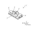
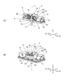
図1は本発明を適用したモータの外観斜視図である。また、図2は本発明を適用したモータの構造を示す説明図であり、図2(a)は断面図、図2(b)はロータを部分的に切り欠いた斜視図である。図1、2に示すXYZ方向は互いに直交する方向である。モータ1は、長方形の回路基板2と、回路基板2の中央部分に取り付けられたモータ本体3と、回路基板2上に実装されたモータ制御ユニット4と、回路基板2の長手方向(X方向)でモータ本体3を挟んだ両側に取り付けられた第1コネクタ5および第2コネクタ6を備えるモータユニットである。第1コネクタ5はモータ本体3の長手方向Xの第1方向−Xに固定されており、第2コネクタ6はモータ本体3の長手方向Xの第2方向+Xに固定されている。ここで、図2(a)では、モータ1を第2方向+Xから見ており、図2(b)では、モータ1を第1方向−Xから見ている。図2(b)ではモータ本体3を構成するロータ本体を部分的に切り欠いて示す。
(Motor structure)
FIG. 1 is an external perspective view of a motor to which the present invention is applied. FIG. 2 is an explanatory view showing the structure of a motor to which the present invention is applied. FIG. 2 (a) is a sectional view and FIG. 2 (b) is a perspective view in which a rotor is partially cut away. The XYZ directions shown in FIGS. 1 and 2 are directions orthogonal to each other. The
回路基板2は、アルミニウム製の基材の片面(表面)にビルドアップ工法により多層の配線層および絶縁層を形成したものである。回路基板2の中央部分には、図2(a)に示すように、モータ本体3を固定するための固定孔11(固定部)が設けられている。
The
回路基板2は、配線層内の配線パターンに接続されるランドを備える。このランドを介して、モータ制御ユニット4の端子が回路基板2に接続される。また、回路基板2は、ランドと重なる位置に形成されたビアフィルメッキによって複数の配線層が導通する。回路基板2は、モータ制御ユニット4の熱が、モータ制御ユニット4の端子から回路基板2のランドおよびビアフィルメッキを介して、熱伝導率の高い絶縁層に伝達され、アルミニウム製の基材にまで伝わる。従って、基材を介して、モータ制御ユニット4の熱を効率よく放熱することが可能である。
The
モータ制御ユニット4としては、例えば、ウエハーレベルチップサイズパッケージ(WLCSP)を用いる。モータ制御ユニット4は、モータ本体3を駆動するためのドライバ回路、モータ本体3の駆動を制御するためのコントローラ回路、および、アンプ回路等を備える。つまり、本例のモータ1は、モータ本体3と当該モータ本体3の制御基板を一体化したものである。
For example, a wafer level chip size package (WLCSP) is used as the
モータ本体3は3相永久磁石同期モータ(PMSM)である。モータ本体3は、ステータ12と、出力軸13を備えるロータ14と、固定孔11を貫通した状態でステータ12を支持するスリーブ15と、スリーブ15に固定されたベアリング16を有する。モータ本体3の軸線L(出力軸13の回転中心線)は、回路基板2と直交する方向(Z方向)に延びる。ベアリング16はスリーブ15における回路基板2の裏面2bの側の端部分に固定されている。ベアリング16は、出力軸13(ロータ14)を軸線L回りに回転可能に支持する。
The
ステータ12は、半径方向に突出する複数の突極を備える環状のステータコア18と、各突極に巻き回された駆動コイル19を備える。ステータコア18は回路基板2の表面2aの側に位置する。ステータコア18の中心穴には、スリーブ15において回路基板2の表面2aの側に突出した表面側突出部分が挿入されている。これにより、ステータコア18はスリーブ15を介して回路基板2に固定される。
The
ロータ14は、円形の底板部21と底板部21の外周縁部分から回路基板2の側に向って延びる環状板部22を備えるロータケース23と、環状板部22の内周面に固定された駆動マグネット24を備える。出力軸13は底板部21の中心に固定されて環状板部22の内側をロータケース23と同軸に延びる。出力軸13はロータケース23の円形開口部(回路基板2の側の開口)から突出する。
The
ロータ14は、ロータケース23が回路基板2の表面2aの側からステータコア18に被せられ、出力軸13がスリーブ15に挿入され、出力軸13の先端部分がスリーブ15から回路基板2の裏面2bの側に突出した状態に組み付けられる。これにより、ステータコア18の突極と駆動マグネット24が径方向に対向する。
In the
駆動マグネット24は、回路基板2の表面2aに実装された第1ホール素子25および第2ホール素子26と所定間隔で対向する。第1ホール素子25と第2ホール素子26は、ロータ14の軸線Lを中心として見た場合に、周方向に離れた位置に配置される。ステータ12は3相の駆動コイル19を備えており、第1ホール素子25と第2ホール素子26は、隣り合う駆動コイル19の隙間に配置される。
The
駆動マグネット24は、正弦波状の着磁パターンで6極着磁されている。ロータ14が回転すると、第1ホール素子25および第2ホール素子26の位置では、駆動マグネット24の回転に伴って周期的な磁界の変化が生じる。第1ホール素子25および第2ホール素子26は、ロータ14の回転に伴う磁界の変化に基づき、周期的に変動する信号Ha、Hbを出力する。第1ホール素子25と第2ホール素子26は、信号Ha、Hbが電気角で120度位相のずれた信号となるように配置されている。なお、信号Ha、Hbの位相のずれが120度以外の値となるように、第1ホール素子25と第2ホール素子26を配置してもよい。
The
(モータ制御ユニット)
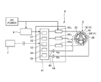
図3はモータ1の制御系の概略ブロック図である。モータ制御ユニット4は、MPU、DSP等を内蔵するコントロールユニット41を備える。コントロールユニット41には、上位装置7からの制御信号が入力され、電源回路8を介して電源が供給される。コントロールユニット41の出力側には、U相、V相、W相の駆動コイル19への通電を制御するドライバ回路42u、42v、42wが接続される。上述したように、モータ本体3は、異なる角度位置に配置された第1ホール素子25および第2ホール素子26を備えており、第1ホール素子25および第2ホール素子26が出力する信号Ha、Hbは、差動アンプ回路43、44で増幅されたのち、コントロールユニット41に入力される。なお、差動アンプ回路43、44は第1ホール素子25および第2ホール素子26の側に組み込まれていても良い。
(Motor control unit)
FIG. 3 is a schematic block diagram of the control system of the
コントロールユニット41は、第1ホール素子25と第2ホール素子26の信号Ha、Hbを最大振幅に対応する係数で除して正規化データに変換する処理を行う正規化処理部51と、予め作成された参照データ等を記憶する記憶部52と、記憶部52で記憶する参照データを用いてロータ14の回転位置を検出する位置検出部53と、参照データを作成するためのキャリブレーションを実行するキャリブレーション実行部54と、位置検出部53で検出した回転位置と目標位置とを比較して、回転位置を目標位置に一致させるための制御信号(PWM信号)をドライバ回路42u、42v、42wに供給するフィードバック制御部55等を備える。
The
(正規化処理)
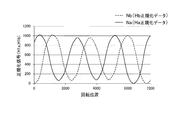
図4は第1ホール素子25の信号Haと第2ホール素子26の信号Hbを正規化した正規化データの説明図であり、ロータ14が1回転する範囲(機械角で360度)の正規化データを示す。図4の横軸はロータ14の回転位置であり、ロータ1回転がパルス数で7200に相当する。また、図4の縦軸はホール素子の信号を正規化した値であり、最大振幅を1024とするように信号Ha、Hbを変換したことを示す。図4の実線は、第1ホール素子25の信号Haを正規化した正規化信号H1aをロータ14が1回転する範囲で生成した第1正規化データNaである。また、図4の破線は、第2ホール素子26の信号Hbを正規化した正規化信号H1bをロータ14が1回転する範囲で生成した第2正規化データNbである。
(Normalization processing)
FIG. 4 is an explanatory diagram of normalized data obtained by normalizing the signal Ha of the
正規化処理部51は、コントロールユニット41に入力された信号Ha、Hbに対してノイズ除去処理を行うフィルタ回路を備えており、ノイズ除去後の信号Ha、Hbに対して正規化処理を行って正規化信号H1a、H1bを求め、第1正規化データNaおよび第2正規化データNbを生成する。また、正規化処理部51は、最大振幅が1024となるように信号Ha、Hbを変換する処理を行うが、この変換処理に用いる係数(例えば、信号Ha、Hbの最大振幅値をそれぞれ1024で除した値)を、予め定めたタイミングで更新する。例えば、一定時間毎に係数を更新する。
The
(参照データ)
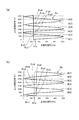
図5は、回転位置の検出処理に用いる参照データの説明図であり、図5(a)は第1参照データのグラフ表示であり、図5(b)は第2参照データのグラフ表示である。キャリブレーション実行部54は、モータ1の製造後、出荷前や修理時、メンテナンス時などの各種のタイミングで、参照用のエンコーダを用いてロータ14の回転位置を検出しながら第1ホール素子25の信号Haおよび第2ホール素子26の信号Hbを検出し、第1参照データRa(図5(a)参照)および第2参照データRb(図5(b)参照)を作成して記憶部52に記憶させるキャリブレーションを実行する。
(Reference data)
FIG. 5 is an explanatory diagram of the reference data used for the rotation position detection process, FIG. 5A is a graph display of the first reference data, and FIG. 5B is a graph display of the second reference data. . The
キャリブレーションを実行するときには、モータ1に参照用のエンコーダを装着し、参照用のエンコーダの信号をモータ制御ユニット4に入力するようにモータ1と参照用のエンコーダとを接続する。この状態で、キャリブレーション実行部54は、まず、ロータ14を1回転させる間、参照用のエンコーダを用いてロータ14の回転位置を検出しながら、第1ホール素子25の信号Haを取得して信号Haを正規化し、且つ、第2ホール素子26の信号Hbを取得して信号Hbを正規化する。これにより、図4の横軸が参照回転位置である場合の、第1正規化データNaおよび第2正規化データNbを求める。
When executing the calibration, a reference encoder is attached to the
続いて、キャリブレーション実行部54は、第1正規化データNaを図5(a)に示す第1参照データRaに変換する。また、第2正規化データNbを図5(b)に示す第2参照データRbに変換する。第1参照データRaは、ロータ1回転分の第1正規化データNaに含まれる、1024段階の正規化信号H1aのそれぞれの値に対して、ロータ14の回転位置(出力回転位置)を対応付けたものである。また、第2参照データRbは、ロータ1回転分の第2正規化データNaに含まれる、1024段階の正規化信号H1bのそれぞれの値に対して、ロータ14の回転位置(出力回転位置)を対応付けたものである。
Subsequently, the
本形態では、駆動マグネット24が6極着磁されているので、ロータ14が1回転する間の、第1ホール素子25および第2ホール素子26の信号の変化は、いずれも、図4に示すような3つのピーク値と3つのボトム値が交互に現れる曲線となる。図5(a)に示すように、第1参照データRaは、隣り合うピーク値とボトム値の間にそれぞれ傾斜部が位置しており、6つの傾斜部A(1)、A(2)、A(3)、A(4)、A(5)、A(6)を備える。同様に、図5(b)に示す第2参照データRbは、隣り合うピーク値とボトム値の間にそれぞれ傾斜部が位置しており、6つの傾斜部B(1)、B(2)、B(3)、B(4)、B(5)、B(6)を備える。
In this embodiment, since the
図5(a)に示すように、第1参照データRaは、横軸上の1つの値(1つの正規化信号H1a)に対して、それぞれ、6個の出力回転位置θa1、θa2、θa3、θa4、θa5、θa6が対応付けられている。出力回転位置θa1〜θa6は、6つの傾斜部A(1)〜A(6)上にそれぞれ1つずつ存在する。すなわち、傾斜部A(1)上に出力回転位置θa1が位置し、傾斜部A(2)上に出力回転位置θa2が位置し、傾斜部A(3)上に出力回転位置θa3が位置し、傾斜部A(4)上に出力回転位置θa4が位置し、傾斜部A(5)上に出力回転位置θa5が位置し、傾斜部A(6)上に出力回転位置θa6が位置する。 As shown in FIG. 5 (a), the first reference data Ra has six output rotation positions θa1, θa2, θa3, and one value (one normalized signal H1a) on the horizontal axis. θa4, θa5, and θa6 are associated with each other. One output rotation position θa1 to θa6 exists on each of the six inclined portions A (1) to A (6). That is, the output rotation position θa1 is positioned on the inclined portion A (1), the output rotation position θa2 is positioned on the inclined portion A (2), and the output rotation position θa3 is positioned on the inclined portion A (3). The output rotation position θa4 is positioned on the inclined portion A (4), the output rotation position θa5 is positioned on the inclined portion A (5), and the output rotation position θa6 is positioned on the inclined portion A (6).
また、図5(b)に示すように、第2参照データRbは、横軸上の1つの値(1つの正規化信号H1b)に対して、それぞれ、6個の出力回転位置θb1、θb2、θb3、θb4、θb5、θb6が対応付けられている。出力回転位置θb1〜θb6は、6つの傾斜部B(1)〜B(6)上にそれぞれ1つずつ存在する。すなわち、傾斜部B(1)上に出力回転位置θb1が位置し、傾斜部B(2)上に出力回転位置θb2が位置し、傾斜部B(3)上に出力回転位置θb3が位置し、傾斜部B(4)上に出力回転位置θb4が位置し、傾斜部B(5)上に出力回転位置θb5が位置し、傾斜部B(6)上に出力回転位置θb6が位置する。 Further, as shown in FIG. 5B, the second reference data Rb has six output rotational positions θb1, θb2, and one value (one normalized signal H1b) on the horizontal axis, respectively. θb3, θb4, θb5, and θb6 are associated with each other. One output rotation position θb1 to θb6 exists on each of the six inclined portions B (1) to B (6). That is, the output rotation position θb1 is located on the inclined portion B (1), the output rotation position θb2 is located on the inclined portion B (2), and the output rotation position θb3 is located on the inclined portion B (3). The output rotation position θb4 is located on the inclined portion B (4), the output rotation position θb5 is located on the inclined portion B (5), and the output rotation position θb6 is located on the inclined portion B (6).
記憶部52が記憶する第1参照データRaと第2参照データRbは、1024段階の正規化信号H1a、H1bのそれぞれに対して、出力回転位置θの値を6個ずつ対応付けたマトリクステーブルである。位置検出部53は、このマトリクステーブルに基づき、必要に応じて線形補完を行って、第1ホール素子25の信号Haおよび第2ホール素子26の信号Hbに対応する回転位置の候補を求める。そして、求めた候補位置の中から、適切な候補位置を選択することにより、回転位置を検出する。
The first reference data Ra and the second reference data Rb stored in the
(回転位置の検出方法)
図6は、参照データを用いた回転位置の検出方法を模式的に示す説明図である。本形態では、ロータ14が検出対象の回転位置θ(0)に位置するときに得られる第1ホール素子25の信号を第1信号Ha(0)とし、ロータ14が検出対象の回転位置θ(0)に位置するときに得られる第2ホール素子26の信号を第2信号Hb(0)とする。位置検出部53は、検出対象の回転位置θ(0)を求める場合には、第1信号Haと第2信号Hbを取得して、これに基づいて第1参照データRaと第2参照データRbを参照して、検出対象の回転位置θ(0)を求める。
(Rotation position detection method)
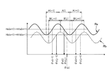
FIG. 6 is an explanatory diagram schematically showing a rotational position detection method using reference data. In this embodiment, the signal of the
具体的には、位置検出部53は、第1信号Haの正規化信号H1a(0)およびと第2信号Hbの正規化信号H1b(0)を求める。しかる後に、第1参照データRaを用いて、正規化信号H1a(0)に対応する回転位置θ(0)の候補を全て抽出する。これにより、6個の第1候補θa1(0)、θa2(0)、θa3(0)、θa4(0)、θa5(0)、θa6(0)が抽出される。同様に、第2参照データRbを用いて、正規化信号H1b(0)に対応する回転位置θ(0)の候補を全て抽出する。これにより、6個の第2候補θb1(0)、θb2(0)、θb3(0)、θb4(0)、θb5(0)、θb6(0)が抽出される。
Specifically, the
図6は、第1信号Ha(0)に対応する全ての第1候補θa1(0)、〜θa6(0)と、第2信号Hb(0)に対応する全ての第2候補θb1(0)〜θb6(0)が横軸上に分布する状態を示す。位置検出部53は、第1候補θa1(0)、〜θa6(0)と、第2候補θb1(0)〜θb6(0)の組み合わせを総当たりで全て求める。そして、求めた組み合わせのそれぞれに対して、2つの候補位置(第1候補と第2候補)の差分を算出する。例えば、第1候補θa1(0)と第2候補θb1(0)の組み合わせに対して、第1候補θa1(0)と第2候補θb1(0)との差分を算出する。同様に、他の組み合わせについても全て差分を算出して、全ての差分の大小を比較する。そして、差分の値が最も小さい組み合わせから、検出対象の回転位置θ(0)を求める。本形態では、差分の値が最も小さい組み合わせを構成する2つの候補位置(第1候補と第2候補)の平均値を、検出対象の回転位置θ(0)とする。例えば、図6に示した例の場合、第1候補θa2(0)と第2候補θb2(0)の組み合わせが横軸上で最も近くに位置しており、第1候補θa2(0)と第2候補θb2(0)の差分が最も小さい。従って、位置検出部53は、第1候補θa2(0)と第2候補θb2(0)の平均値を、検出対象の回転位置θ(0)とする。
FIG. 6 shows all first candidates θa1 (0) to ˜θa6 (0) corresponding to the first signal Ha (0) and all second candidates θb1 (0) corresponding to the second signal Hb (0). ~ Θb6 (0) is shown distributed on the horizontal axis. The
(初期原点の設定)
位置検出部53は、モータ1を駆動開始する前の初期化処理として、上記の検出方法によってロータ14の回転位置(初期回転位置)を検出する処理を行う。初期回転位置を検出する処理は、例えば、モータ1が第1ホール素子25および第2ホール素子26の信号を監視しない状態から、第1ホール素子25および第2ホール素子26の信号を監視する状態に移行した場合に行う。例えば、電源投入時や、一旦休止状態になってから再起動したときなどに、初期回転位置を検出する処理を行う。
(Initial origin setting)
The
位置検出部53は、検出した初期回転位置をロータ14の回転位置の原点に設定する。また、位置検出部53は、初期回転位置を検出する処理で、差分の値が2番目に小さい組み合わせの平均値を、原点を修正するための候補データ(修正候補位置)として記憶部52に記憶させる。例えば、図6の例では、第1候補θa4(0)と第2候補θb4(0)の組み合わせの差分が2番目に小さい。そこで、第1候補θa4(0)と第2候補θb4(0)の平均値θ´(0)を、修正候補位置として記憶部52に記憶させる。
The
第1参照データRaと第2参照データRbは、それぞれ、複数のピーク値と複数のボトム値を持つので、差分の値が近い候補位置の組み合わせが複数存在する。例えば、図6の例では、第1候補θa2(0)と第2候補θb2(0)の組み合わせで最も差分の値が小さいが、第1候補θa4(0)と第2候補θb4(0)の組み合わせや、第1候補θa6(0)と第2候補θb6(0)の組み合わせも差分の値が小さい。従って、第1ホール素子25および第2ホール素子26の出力変動や各種の検出誤差等が生じると、正しい回転位置と異なる候補位置の差分が最も小さい値になってしまう場合があり、この場合には、正しい初期回転位置を検出できない。従って、原点位置がずれて設定されるおそれがある。本形態のコントロールユニット41は、モータ1の駆動開始後、最初に原点に設定した初期回転位置(例えば、図6のθ(0))が正しい回転位置でないことが判明した場合には、記憶部52に記憶させておいた修正候補位置(例えば、図6のθ´(0))を読み出して、原点を修正候補位置に置き換える処理を行う。
Since the first reference data Ra and the second reference data Rb each have a plurality of peak values and a plurality of bottom values, there are a plurality of combinations of candidate positions having close difference values. For example, in the example of FIG. 6, the combination of the first candidate θa2 (0) and the second candidate θb2 (0) has the smallest difference value, but the first candidate θa4 (0) and the second candidate θb4 (0) The combination and the combination of the first candidate θa6 (0) and the second candidate θb6 (0) also have a small difference value. Therefore, if output fluctuations of the
(作用効果)
以上のように、本形態のモータ1は、第1ホール素子25および第2ホール素子26から、ロータ14の回転位置に応じて変化する信号Ha、Hbを得ることができる。そして、この信号Ha、Hbを用いて第1参照データRaおよび第2参照データRbを参照して、回転位置を求めることができる。従って、回転位置検出用のマグネットや光学式エンコーダなどを用いることなく、モータ本体3に2つのホール素子を追加するだけでロータ14の回転位置を検出できる。よって、モータ本体3の小型化および低コスト化に有利である。また、予めモータ1毎にキャリブレーションを行って作成した第1参照データRaおよび第2参照データRbを用いて回転位置を判定するので、簡単なアルゴリズムで、精度良く回転位置を検出できる。また、検出した回転位置を用いてフィードバック制御を行うことにより、精度良くモータ1の回転を制御できる。
(Function and effect)
As described above, the
本形態の位置検出部53は、第1参照データRaと第2参照データRbから、第1信号Ha(0)に対応する回転位置の候補である第1候補θa1(0)〜θa6(0)と、第2信号Hb(0)に対応する回転位置の候補である第2候補θb1(0)〜θb6(0)の組み合わせを全て求め、求めた全ての組み合わせに対して、2つの候補位置の差分を算出し、該差分の値が最も小さい組み合わせを構成する2つの候補位置の平均値を検出対象の回転位置θ(0)とする。従って、簡単なアルゴリズムで、精度良く回転位置を検出できる。
The
本形態では、モータ1の初期化処理で検出した回転位置を原点に設定する。従って、以降は原点からの角度差に基づいて回転位置を検出でき、インクリメンタルエンコーダの機能を持たせることができる。従って、インクリメンタルな制御を行うことができる。なお、本形態は6極着磁された駆動マグネット24を用いているが、他の極数にすることもできる。例えば、2極着磁の駆動マグネットを用いれば、電気角と機械角が一致するので、アブソリュートエンコーダの機能を持たせることができる。
In this embodiment, the rotational position detected in the initialization process of the
本形態では、モータ1の初期化処理で回転位置を検出する場合に、2つの候補位置の差分の値が最も小さい組み合わせだけでなく、2つの候補位置の差分の値が2番目に小さい組み合わせを求め、この組み合わせを構成する2つの候補位置の平均値を、原点を修正す
るための修正候補位置として記憶する。従って、原点に設定した位置が正確でなかった場合に、修正候補位置を用いて簡単かつ速やかに原点を修正できる。
In this embodiment, when the rotation position is detected in the initialization process of the
本形態では、第1ホール素子25の信号Haおよび第2ホール素子26の信号Hbを正規化した正規化信号H1a、H1bに基づいて第1参照データRaおよび第2参照データRbを参照して、ロータ14の回転位置を求めるので、2つのホール素子間の感度バラツキや実装位置差の影響を少なくすることができる。
In this embodiment, referring to the first reference data Ra and the second reference data Rb based on the normalized signals H1a and H1b obtained by normalizing the signal Ha of the
本形態では、予め設定したタイミングで、第1ホール素子25の信号Haおよび第2ホール素子26の信号Hbを正規化する処理に用いる係数を更新するので、周囲温度や供給電圧等の変動による、ホール素子の信号変動の影響を少なくすることができる。従って、精度良く回転位置を検出できる。
In this embodiment, the coefficient used for normalizing the signal Ha of the
本形態では、駆動マグネット24の着磁パターンが正弦波状であるため、ロータ14の回転に伴う第1ホール素子25と第2ホール素子26の信号の変化が緩やかである。従って、回転位置の分解能が高い参照データを得ることができ、参照データを用いて回転位置を検出する場合の検出精度が高まる。なお、駆動マグネット24の着磁パターンが正弦波状でなくても、モータ1の回転位置を検出することは可能である。
In this embodiment, since the magnetization pattern of the
(変形例)
上記形態は、第1参照データRaと第2参照データRbから、第1信号Ha(0)と第2信号Hb(0)に対応する回転位置の候補を全て求め、2つの候補位置(第1候補と第2候補)の組み合わせを総当たりで作成し、その全てについて2つの候補位置の差分を算出して、差分の値が最も小さい組み合わせを探していたが、2つの候補位置(第1候補と第2候補)の組み合わせの数を減らすことも可能である。
(Modification)
In the above embodiment, all candidates for rotational positions corresponding to the first signal Ha (0) and the second signal Hb (0) are obtained from the first reference data Ra and the second reference data Rb, and two candidate positions (first The combinations of the candidate and the second candidate) are created with brute force, the difference between the two candidate positions is calculated for all of them, and the combination having the smallest difference value is searched for. And the number of combinations of the second candidate) can be reduced.
例えば、図6に示すように第1候補と第2候補がそれぞれ6つずつ存在する場合には、総当たりの場合には組み合わせの数が36通りであるのに対し、2つの候補位置(第1候補と第2候補)の組み合わせを隣り合う第1候補と第2候補の組み合わせに限定すれば、組み合わせの数を9通りに減らすことができる。従って、短時間で回転位置を検出することができる。 For example, as shown in FIG. 6, when there are six first candidates and six second candidates, there are 36 combinations in the case of round robin, whereas there are two candidate positions (first If the combination of the first candidate and the second candidate) is limited to the combination of the first candidate and the second candidate that are adjacent to each other, the number of combinations can be reduced to nine. Therefore, the rotational position can be detected in a short time.
また、上記形態では、第1参照データRaの6つの傾斜部A(1)〜A(6)から、第1信号Ha(0)に対応する回転位置の候補(第1候補)を1つずつ求め、第2参照データRbの6つの傾斜部B(1)〜B(6)から、第2信号Hb(0)に対応する回転位置の候補(第2候補)を1つずつ求めていたため、第1候補と第2候補がそれぞれ6つずつ存在していたが、第1候補と第2候補をより少ない数に限定することもできる。 Moreover, in the said form, the candidate (1st candidate) of the rotation position corresponding to 1st signal Ha (0) one by one from six inclination part A (1) -A (6) of 1st reference data Ra. Since the rotation position candidates (second candidates) corresponding to the second signal Hb (0) are obtained one by one from the six inclined portions B (1) to B (6) of the second reference data Rb, Although there are six first candidates and six second candidates, it is also possible to limit the number of first candidates and second candidates to a smaller number.
図7は、変形例の回転位置の検出方法の説明図である。例えば、回転位置を繰り返し検出する場合で、直近に検出した回転位置がθ(n)である場合には、直近に検出した回転位置θ(n)に基づき、第1候補と第2候補を3つずつに限定して抽出することができる。具体的には、第1参照データRaの6つの傾斜部A(1)〜A(6)のうち、直近に検出した回転位置θ(n)を含む傾斜部A(i)とその両側に位置する傾斜部A(i−1)、A(i+1)の範囲に限って第1候補θa(i−1)、θa(i)、θa(i+1)の3つを求める。また、第2参照データRbの6つの傾斜部B(1)〜B(6)のうち、直近に検出した回転位置θ(n)を含む傾斜部B(j)とその両側に位置する傾斜部B(j−1)、B(j+1)の範囲に限って第2候補θb(j−1)、θb(j)、θb(j+1)の3つを求める。このように、直近に検出した回転位置θ(n)を含む傾斜部A(i)、傾斜部B(j)を中心とする連続した3つの傾斜部A(i−1)〜A(i+1)、傾斜部B(j−1)〜B(j+1)に限って候補位置を取得すれば、第1候補と第2候補を
3つずつに限って求めることができる。その結果、第1候補と第2候補の組み合わせの数は、総当たりで作成しても9通りである。従って、短時間で回転位置を検出することができる。また、この方法では、直近に検出した回転位置θ(n)に近い位置を候補位置としているので、回転位置の検出精度が低下するおそれは少ない。
FIG. 7 is an explanatory diagram of a rotation position detection method according to a modification. For example, when the rotation position is repeatedly detected and the most recently detected rotation position is θ (n), the first candidate and the second candidate are determined based on the most recently detected rotation position θ (n). Extraction can be limited to one by one. Specifically, among the six inclined portions A (1) to A (6) of the first reference data Ra, the inclined portion A (i) including the most recently detected rotational position θ (n) and positions on both sides thereof. The first candidates θa (i−1), θa (i), and θa (i + 1) are obtained only in the range of the inclined portions A (i−1) and A (i + 1). Of the six inclined portions B (1) to B (6) of the second reference data Rb, the inclined portion B (j) including the most recently detected rotational position θ (n) and the inclined portions located on both sides thereof. Three second candidates θb (j−1), θb (j), and θb (j + 1) are obtained only in the range of B (j−1) and B (j + 1). In this way, three consecutive inclined portions A (i−1) to A (i + 1) centered on the inclined portion A (i) and the inclined portion B (j) including the most recently detected rotational position θ (n). If candidate positions are acquired only in the inclined portions B (j−1) to B (j + 1), the first candidate and the second candidate can be obtained only in three. As a result, the number of combinations of the first candidate and the second candidate is nine even if created in a round robin. Therefore, the rotational position can be detected in a short time. Further, in this method, since the position close to the most recently detected rotational position θ (n) is set as the candidate position, there is little possibility that the detection accuracy of the rotational position is lowered.
あるいは、上記のように、直近に検出した回転位置θ(n)を含む傾斜部A(i)、傾斜部B(j)を中心とする3つの傾斜部A(i−1)〜A(i+1)および傾斜部B(j−1)〜B(j+1)に限定して候補位置を取得する場合には、第1候補と第2候補のどちらかが、直近に検出した回転位置θ(n)を含む傾斜部A(i)、傾斜部B(j)に存在する候補位置であるような組み合わせに限定してもよい。具体的には、第1候補θa(i)と第2候補θb(j)、第1候補θa(i)と第2候補θb(j−1)、第1候補θa(i)と第2候補θb(j+1)、第1候補θa(i−1)と第2候補θb(j)、第1候補θa(i+1)と第2候補θb(j)の5通りの組み合わせに限定する。この場合には、更に組み合わせの数が減るので、短時間で回転位置を検出することができる。 Alternatively, as described above, the three inclined portions A (i−1) to A (i + 1) centered on the inclined portion A (i) and the inclined portion B (j) including the most recently detected rotational position θ (n). ) And inclined portions B (j−1) to B (j + 1), when acquiring candidate positions, the rotation position θ (n) detected most recently by either the first candidate or the second candidate. May be limited to combinations that are candidate positions existing in the inclined portion A (i) and the inclined portion B (j). Specifically, the first candidate θa (i) and the second candidate θb (j), the first candidate θa (i) and the second candidate θb (j−1), the first candidate θa (i) and the second candidate It is limited to five combinations of θb (j + 1), first candidate θa (i−1) and second candidate θb (j), and first candidate θa (i + 1) and second candidate θb (j). In this case, since the number of combinations is further reduced, the rotational position can be detected in a short time.
また、上記形態の第1参照データRaと第2参照データRbは、それぞれ3つのピーク値と3つのボトム値を持つが、これらの値は完全に一致することはない。このように、3つのピーク値と3つのボトム値が完全に一致することがなく、これらの値の大小関係がモータ固有の特性であるとすれば、ピーク値とボトム値の大小関係とその配列順を識別して、どのピーク値とどのボトム値の間に回転位置が存在するかを判定することが可能である。従って、予め、3つのピーク値と3つのボトム値の大小関係とその配列順のデータを作成して記憶部52に記憶させておけば、絶対位置および回転方向を検出することが可能である。
In addition, the first reference data Ra and the second reference data Rb in the above form have three peak values and three bottom values, respectively, but these values do not completely match. As described above, if the three peak values and the three bottom values do not completely coincide with each other, and the magnitude relationship between these values is characteristic of the motor, the magnitude relationship between the peak value and the bottom value and the arrangement thereof. It is possible to identify the order and determine which peak value and which bottom value a rotational position exists. Therefore, if the magnitude relationship between the three peak values and the three bottom values and the data in the arrangement order are created and stored in the
1…モータ
2…回路基板
2a…表面
2b…裏面
3…モータ本体
4…モータ制御ユニット
5…第1コネクタ
6…第2コネクタ
7…上位装置
8…電源回路
11…固定孔
12…ステータ
13…出力軸
14…ロータ
15…スリーブ
16…ベアリング
18…ステータコア
19…駆動コイル
21…底板部
22…環状板部
23…ロータケース
24…駆動マグネット
25…第1ホール素子
26…第2ホール素子
41…コントロールユニット
42u、42v、43w…ドライバ回路
43、44…差動アンプ回路
51…正規化処理部
52…記憶部
53…位置検出部
54…キャリブレーション実行部
55…フィードバック制御部
A(1)〜A(6)…傾斜部
B(1)〜B(6)…傾斜部
H1a…正規化信号
H1b…正規化信号
Ha…第1信号(第1ホール素子の信号)
Hb…第2信号(第1ホール素子の信号)
L…軸線
Na…第1正規化データ
Nb…第2正規化データ
Ra…第1参照データ
Rb…第2参照データ
DESCRIPTION OF
Hb ... 2nd signal (1st Hall element signal)
L ... Axis Na ... First normalized data Nb ... Second normalized data Ra ... First reference data Rb ... Second reference data
Claims (11)
前記ロータが備える駆動マグネットに対して異なる角度位置で対向する第1ホール素子および第2ホール素子と、
前記ロータの回転位置と、該回転位置で得られる前記第1ホール素子の信号および前記第2ホール素子の信号と、を対応付けた参照データを記憶する記憶部と、
前記ロータが検出対象の回転位置にあるときの、前記第1ホール素子および前記第2ホール素子の信号をそれぞれ、第1信号および第2信号とするとき、前記第1信号および前記第2信号に基づいて前記参照データを参照して、前記検出対象の回転位置を求める位置検出部と、を有することを特徴とするモータ。 A rotor and a stator;
A first Hall element and a second Hall element facing the drive magnet included in the rotor at different angular positions;
A storage unit for storing reference data in which the rotational position of the rotor is associated with the signal of the first Hall element and the signal of the second Hall element obtained at the rotational position;
When the signals of the first Hall element and the second Hall element when the rotor is in the rotation position to be detected are the first signal and the second signal, respectively, the first signal and the second signal And a position detecting unit that obtains a rotational position of the detection target with reference to the reference data based on the reference data.
前記参照データから、前記第1信号に対応する回転位置の候補である第1候補と、前記第2信号に対応する回転位置の候補である第2候補と、の組み合わせを全て求め、
前記求めた組み合わせのそれぞれに対して、前記第1候補と前記第2候補との差分を算出し、該差分の値が最も小さい組み合わせから、前記検出対象の回転位置を求めることを特徴とする請求項1に記載のモータ。 The position detector is
From the reference data, all combinations of a first candidate that is a candidate for a rotational position corresponding to the first signal and a second candidate that is a candidate for a rotational position corresponding to the second signal are obtained,
The difference between the first candidate and the second candidate is calculated for each of the obtained combinations, and the rotation position of the detection target is obtained from the combination having the smallest difference value. Item 4. The motor according to Item 1.
前記第1信号に対応する回転位置の候補である第1候補と、前記第2信号に対応する回転位置の候補である第2候補のうち、隣り合う回転位置の候補である前記第1候補と前記第2候補の組み合わせを全て求め、
前記求めた組み合わせのそれぞれに対して、前記第1候補と前記第2候補との差分を算出し、前記差分の値が最も小さい組み合わせから、前記検出対象の回転位置を求めることを特徴とする請求項1または2に記載のモータ。 The position detector is
A first candidate that is a candidate for a rotational position corresponding to the first signal and a second candidate that is a candidate for a rotational position corresponding to the second signal; Find all combinations of the second candidates,
The difference between the first candidate and the second candidate is calculated for each of the obtained combinations, and the rotation position of the detection target is obtained from the combination having the smallest difference value. Item 3. The motor according to Item 1 or 2.
前記参照データは、前記ロータの回転位置と、該回転位置で得られる前記第1ホール素子の信号とを対応づけた第1参照データ、および、前記ロータの回転位置と、該回転位置で得られる前記第2ホール素子の信号とを対応付けた第2参照データを含み、
前記第1参照データと前記第2参照データは、それぞれ、複数のピーク値および複数のボトム値を備え、且つ、隣り合う前記ピーク値と前記ボトム値の間に位置する傾斜部を複数備え、
前記位置検出部は、
前記第1参照データを参照して、直近に検出した前記ロータの回転位置を含む前記傾斜部およびその両側に位置する2つの前記傾斜部から、それぞれ1つずつ前記第1候補を求め、
前記第2参照データを参照して、直近に検出した前記ロータの回転位置を含む前記傾斜部およびその両側に位置する2つの前記傾斜部から、それぞれ1つずつ前記第2候補を求め、
前記求めた3つの前記第1候補と、前記求めた3つの前記第2候補の組み合わせの中で、前記第1候補と前記第2候補との差分が最も小さい組み合わせから、前記検出対象の回転位置を求めることを特徴とする請求項2または3に記載のモータ。 The number of poles of the drive magnet is 4 or more;
The reference data is obtained from first reference data that associates the rotational position of the rotor with the signal of the first Hall element obtained at the rotational position, and the rotational position of the rotor and the rotational position. Including second reference data associated with a signal of the second Hall element;
Each of the first reference data and the second reference data includes a plurality of peak values and a plurality of bottom values, and includes a plurality of inclined portions located between the adjacent peak values and the bottom values,
The position detector is
With reference to the first reference data, the first candidate is obtained one by one from the inclined portion including the rotation position of the rotor detected most recently and the two inclined portions located on both sides thereof,
With reference to the second reference data, the second candidate is obtained one by one from the inclined part including the rotation position of the rotor detected most recently and the two inclined parts located on both sides thereof,
Among the combinations of the three obtained first candidates and the three obtained second candidates, the rotation position of the detection target is selected from the combination having the smallest difference between the first candidate and the second candidate. The motor according to claim 2, wherein the motor is obtained.
前記3つの前記第1候補と、前記3つの前記第2候補の組み合わせの中から、前記第1候補と前記第2候補のどちらかまたは両方が、直近に検出した前記ロータの回転位置を含む前記傾斜部に位置する組み合わせを求め、
前記求めた組み合わせの中で、前記第1候補と前記第2候補との差分が最も小さい組み
合わせから、前記検出対象の回転位置を求めることを特徴とする請求項4に記載のモータ。 The position detector is
Among the combinations of the three first candidates and the three second candidates, one or both of the first candidate and the second candidate includes the rotation position of the rotor detected most recently. Find the combination located on the slope,
5. The motor according to claim 4, wherein the rotation position of the detection target is obtained from a combination having the smallest difference between the first candidate and the second candidate among the obtained combinations.
前記第1候補と前記第2候補との差分が最も小さい組み合わせから求めた回転位置を、前記ロータの回転位置の原点に設定することを特徴とする請求項2ないし5のいずれかの項に記載のモータ。 The position detector is
6. The rotation position obtained from a combination having the smallest difference between the first candidate and the second candidate is set as an origin of the rotation position of the rotor. 6. Motor.
前記第1候補と前記第2候補との差分が2番目に小さい組み合わせから求めた回転位置を、前記原点を修正するための修正候補位置として記憶することを特徴とする請求項6に記載のモータ。 The storage unit
The motor according to claim 6, wherein a rotational position obtained from a combination having the second smallest difference between the first candidate and the second candidate is stored as a correction candidate position for correcting the origin. .
前記第1ホール素子の信号および前記第2ホール素子の信号を正規化した正規化データに基づいて前記参照データを参照して、前記ロータの回転位置を求めることを特徴とする請求項1ないし7のいずれかの項に記載のモータ。 The position detector is
8. The rotational position of the rotor is obtained by referring to the reference data based on normalized data obtained by normalizing the signal of the first Hall element and the signal of the second Hall element. The motor according to any one of the items.
予め設定したタイミングで、前記第1ホール素子の信号および前記第2ホール素子の信号を正規化する処理に用いる係数を更新することを特徴とする請求項8に記載のモータ。 The position detector is
9. The motor according to claim 8, wherein a coefficient used for processing for normalizing the signal of the first Hall element and the signal of the second Hall element is updated at a preset timing.
前記位置検出部は、
前記複数のピーク値および前記複数のボトム値の大小関係および配列順に基づき、前記ロータの現在位置を求めることを特徴とする請求項1ないし9のいずれかの項に記載のモータ。 The reference data includes a plurality of peak values and a plurality of bottom values,
The position detector is
10. The motor according to claim 1, wherein a current position of the rotor is obtained based on a magnitude relationship and an arrangement order of the plurality of peak values and the plurality of bottom values.
The motor according to any one of claims 1 to 10, wherein the magnetizing pattern of the drive magnet is sinusoidal.
Priority Applications (4)
| Application Number | Priority Date | Filing Date | Title |
|---|---|---|---|
| JP2015125730A JP2017011902A (en) | 2015-06-23 | 2015-06-23 | motor |
| US15/739,447 US20180234040A1 (en) | 2015-06-23 | 2016-06-15 | Motor |
| CN201680036506.5A CN107750428A (en) | 2015-06-23 | 2016-06-15 | Motor |
| PCT/JP2016/067830 WO2016208474A1 (en) | 2015-06-23 | 2016-06-15 | Motor |
Applications Claiming Priority (1)
| Application Number | Priority Date | Filing Date | Title |
|---|---|---|---|
| JP2015125730A JP2017011902A (en) | 2015-06-23 | 2015-06-23 | motor |
Publications (1)
| Publication Number | Publication Date |
|---|---|
| JP2017011902A true JP2017011902A (en) | 2017-01-12 |
Family
ID=57585631
Family Applications (1)
| Application Number | Title | Priority Date | Filing Date |
|---|---|---|---|
| JP2015125730A Pending JP2017011902A (en) | 2015-06-23 | 2015-06-23 | motor |
Country Status (4)
| Country | Link |
|---|---|
| US (1) | US20180234040A1 (en) |
| JP (1) | JP2017011902A (en) |
| CN (1) | CN107750428A (en) |
| WO (1) | WO2016208474A1 (en) |
Cited By (3)
| Publication number | Priority date | Publication date | Assignee | Title |
|---|---|---|---|---|
| JP6438176B1 (en) * | 2018-02-16 | 2018-12-12 | 株式会社 五十嵐電機製作所 | DC motor control device |
| CN113890429A (en) * | 2021-10-29 | 2022-01-04 | 广东工业大学 | Hall element-based motor reducer absolute angle fitting system and fitting method |
| JP7490602B2 (en) | 2021-03-10 | 2024-05-27 | 株式会社東芝 | Brushless motor drive unit |
Families Citing this family (1)
| Publication number | Priority date | Publication date | Assignee | Title |
|---|---|---|---|---|
| JP6967040B2 (en) * | 2019-07-25 | 2021-11-17 | 株式会社ソニー・インタラクティブエンタテインメント | Electric angle calculation device, electric angle calculation method and program |
Family Cites Families (8)
| Publication number | Priority date | Publication date | Assignee | Title |
|---|---|---|---|---|
| US4507591A (en) * | 1983-07-26 | 1985-03-26 | Rca Corporation | Linear pulse width to current converter for brushless DC motors |
| US4697125A (en) * | 1986-03-24 | 1987-09-29 | Performance Controls, Inc. | Method and apparatus for determining shaft position and for providing commutation signals |
| US5969489A (en) * | 1996-07-31 | 1999-10-19 | Victor Company Of Japan, Ltd. | Motor driving system for driving brushless motor |
| JP2001119914A (en) * | 1999-10-15 | 2001-04-27 | Yamaha Motor Co Ltd | Detector for rotor position of motor |
| DE10249641A1 (en) * | 2002-10-24 | 2004-05-06 | Iropa Ag | Sensor system and method for vector control |
| GB2413905B (en) * | 2004-05-05 | 2006-05-03 | Imra Europ S A S Uk Res Ct | Permanent magnet synchronous motor and controller therefor |
| JP5477292B2 (en) * | 2008-08-26 | 2014-04-23 | 株式会社ニコン | Encoder system and signal processing method |
| JP6014989B2 (en) * | 2011-10-28 | 2016-10-26 | 株式会社リコー | Motor drive control apparatus and method |
-
2015
- 2015-06-23 JP JP2015125730A patent/JP2017011902A/en active Pending
-
2016
- 2016-06-15 US US15/739,447 patent/US20180234040A1/en not_active Abandoned
- 2016-06-15 CN CN201680036506.5A patent/CN107750428A/en not_active Withdrawn
- 2016-06-15 WO PCT/JP2016/067830 patent/WO2016208474A1/en active Application Filing
Cited By (4)
| Publication number | Priority date | Publication date | Assignee | Title |
|---|---|---|---|---|
| JP6438176B1 (en) * | 2018-02-16 | 2018-12-12 | 株式会社 五十嵐電機製作所 | DC motor control device |
| WO2019159311A1 (en) * | 2018-02-16 | 2019-08-22 | 株式会社五十嵐電機製作所 | Control device for dc motor |
| JP7490602B2 (en) | 2021-03-10 | 2024-05-27 | 株式会社東芝 | Brushless motor drive unit |
| CN113890429A (en) * | 2021-10-29 | 2022-01-04 | 广东工业大学 | Hall element-based motor reducer absolute angle fitting system and fitting method |
Also Published As
| Publication number | Publication date |
|---|---|
| US20180234040A1 (en) | 2018-08-16 |
| CN107750428A (en) | 2018-03-02 |
| WO2016208474A1 (en) | 2016-12-29 |
Similar Documents
| Publication | Publication Date | Title |
|---|---|---|
| JP5824660B2 (en) | Phase shift detection device, motor drive device, brushless motor, and phase shift detection method | |
| WO2016208474A1 (en) | Motor | |
| JP2018537942A5 (en) | ||
| US9893590B2 (en) | Inner-rotor brushless motor | |
| KR20200002823A (en) | Rotation Angle Detection Device and Rotation Angle Detection Method | |
| WO2018150908A1 (en) | Motor control device and method for controlling motor control device | |
| JP6695247B2 (en) | Motor control device and control method of motor control device | |
| JP5672507B2 (en) | Rotating electric machine | |
| JP2015211593A (en) | Rotational position detection device, and brushless dc motor sinusoidal wave drive controller employing the rotational position detection device | |
| JP2016133376A (en) | Rotation angle detection device | |
| JP5676558B2 (en) | Motor for linear and rotary motion | |
| KR101749522B1 (en) | A device of Hall sensors installation position error correction for BLDC motors having linear Hall sensors and a method thereof | |
| JP6504261B2 (en) | Method and apparatus for manufacturing rotor of motor | |
| KR101655297B1 (en) | Apparatus for correcting position of linear hole sensor and control method of thereof | |
| JP6844617B2 (en) | Motor modules, motor step motion control systems, and motor controls | |
| JP2014168361A (en) | Motor | |
| JP2008178237A (en) | Magnetic pole position correcting method of linear system, and linear system using the same | |
| JP6791013B2 (en) | Two-axis integrated motor | |
| JP5749535B2 (en) | motor | |
| JP2018031677A (en) | motor | |
| US10910921B2 (en) | Device for detecting position of rotor, and motor comprising same | |
| JP2018064340A (en) | Motor controller | |
| JP2015231242A (en) | Dc motor and control method of dc motor | |
| JP2017083357A (en) | Rotor centering method of reluctance resolver | |
| JP2006325311A (en) | Dc brushless motor apparatus and rotary vacuum pump |