JP2016533856A - Conditional mandatory priming - Google Patents
Conditional mandatory priming Download PDFInfo
- Publication number
- JP2016533856A JP2016533856A JP2016543402A JP2016543402A JP2016533856A JP 2016533856 A JP2016533856 A JP 2016533856A JP 2016543402 A JP2016543402 A JP 2016543402A JP 2016543402 A JP2016543402 A JP 2016543402A JP 2016533856 A JP2016533856 A JP 2016533856A
- Authority
- JP
- Japan
- Prior art keywords
- priming
- fluid
- release
- time length
- control unit
- Prior art date
- Legal status (The legal status is an assumption and is not a legal conclusion. Google has not performed a legal analysis and makes no representation as to the accuracy of the status listed.)
- Pending
Links
- 230000037452 priming Effects 0.000 title claims abstract description 130
- 239000012530 fluid Substances 0.000 claims abstract description 144
- 238000000034 method Methods 0.000 claims abstract description 56
- 230000008569 process Effects 0.000 claims abstract description 45
- 238000012360 testing method Methods 0.000 claims abstract description 30
- 238000007599 discharging Methods 0.000 claims abstract description 8
- 239000003814 drug Substances 0.000 claims description 95
- 229940079593 drug Drugs 0.000 claims description 92
- 238000002347 injection Methods 0.000 claims description 34
- 239000007924 injection Substances 0.000 claims description 34
- 230000008878 coupling Effects 0.000 claims description 11
- 238000010168 coupling process Methods 0.000 claims description 11
- 238000005859 coupling reaction Methods 0.000 claims description 11
- 230000003213 activating effect Effects 0.000 claims description 4
- 230000000977 initiatory effect Effects 0.000 claims description 2
- 239000007788 liquid Substances 0.000 claims 1
- JUFFVKRROAPVBI-PVOYSMBESA-N chembl1210015 Chemical compound C([C@@H](C(=O)N[C@@H]([C@@H](C)CC)C(=O)N[C@@H](CCC(O)=O)C(=O)N[C@@H](CC=1C2=CC=CC=C2NC=1)C(=O)N[C@@H](CC(C)C)C(=O)N[C@@H](CCCCN)C(=O)N[C@@H](CC(=O)N[C@H]1[C@@H]([C@@H](O)[C@H](O[C@H]2[C@@H]([C@@H](O)[C@@H](O)[C@@H](CO[C@]3(O[C@@H](C[C@H](O)[C@H](O)CO)[C@H](NC(C)=O)[C@@H](O)C3)C(O)=O)O2)O)[C@@H](CO)O1)NC(C)=O)C(=O)NCC(=O)NCC(=O)N1[C@@H](CCC1)C(=O)N[C@@H](CO)C(=O)N[C@@H](CO)C(=O)NCC(=O)N[C@@H](C)C(=O)N1[C@@H](CCC1)C(=O)N1[C@@H](CCC1)C(=O)N1[C@@H](CCC1)C(=O)N[C@@H](CO)C(N)=O)NC(=O)[C@H](CC(C)C)NC(=O)[C@H](CCCNC(N)=N)NC(=O)[C@@H](NC(=O)[C@H](C)NC(=O)[C@H](CCC(O)=O)NC(=O)[C@H](CCC(O)=O)NC(=O)[C@H](CCC(O)=O)NC(=O)[C@H](CCSC)NC(=O)[C@H](CCC(N)=O)NC(=O)[C@H](CCCCN)NC(=O)[C@H](CO)NC(=O)[C@H](CC(C)C)NC(=O)[C@H](CC(O)=O)NC(=O)[C@H](CO)NC(=O)[C@@H](NC(=O)[C@H](CC=1C=CC=CC=1)NC(=O)[C@@H](NC(=O)CNC(=O)[C@H](CCC(O)=O)NC(=O)CNC(=O)[C@@H](N)CC=1NC=NC=1)[C@@H](C)O)[C@@H](C)O)C(C)C)C1=CC=CC=C1 JUFFVKRROAPVBI-PVOYSMBESA-N 0.000 description 82
- RLSSMJSEOOYNOY-UHFFFAOYSA-N m-cresol Chemical compound CC1=CC=CC(O)=C1 RLSSMJSEOOYNOY-UHFFFAOYSA-N 0.000 description 76
- 108010011459 Exenatide Proteins 0.000 description 48
- 208000028659 discharge Diseases 0.000 description 48
- 229960001519 exenatide Drugs 0.000 description 48
- 101000976075 Homo sapiens Insulin Proteins 0.000 description 22
- 238000012377 drug delivery Methods 0.000 description 22
- PBGKTOXHQIOBKM-FHFVDXKLSA-N insulin (human) Chemical compound C([C@@H](C(=O)N[C@@H](CC(C)C)C(=O)N[C@H]1CSSC[C@H]2C(=O)N[C@H](C(=O)N[C@@H](CO)C(=O)N[C@H](C(=O)N[C@H](C(N[C@@H](CO)C(=O)N[C@@H](CC(C)C)C(=O)N[C@@H](CC=3C=CC(O)=CC=3)C(=O)N[C@@H](CCC(N)=O)C(=O)N[C@@H](CC(C)C)C(=O)N[C@@H](CCC(O)=O)C(=O)N[C@@H](CC(N)=O)C(=O)N[C@@H](CC=3C=CC(O)=CC=3)C(=O)N[C@@H](CSSC[C@H](NC(=O)[C@H](C(C)C)NC(=O)[C@H](CC(C)C)NC(=O)[C@H](CC=3C=CC(O)=CC=3)NC(=O)[C@H](CC(C)C)NC(=O)[C@H](C)NC(=O)[C@H](CCC(O)=O)NC(=O)[C@H](C(C)C)NC(=O)[C@H](CC(C)C)NC(=O)[C@H](CC=3NC=NC=3)NC(=O)[C@H](CO)NC(=O)CNC1=O)C(=O)NCC(=O)N[C@@H](CCC(O)=O)C(=O)N[C@@H](CCCNC(N)=N)C(=O)NCC(=O)N[C@@H](CC=1C=CC=CC=1)C(=O)N[C@@H](CC=1C=CC=CC=1)C(=O)N[C@@H](CC=1C=CC(O)=CC=1)C(=O)N[C@@H]([C@@H](C)O)C(=O)N1[C@@H](CCC1)C(=O)N[C@@H](CCCCN)C(=O)N[C@@H]([C@@H](C)O)C(O)=O)C(=O)N[C@@H](CC(N)=O)C(O)=O)=O)CSSC[C@@H](C(N2)=O)NC(=O)[C@H](CCC(N)=O)NC(=O)[C@H](CCC(O)=O)NC(=O)[C@H](C(C)C)NC(=O)[C@@H](NC(=O)CN)[C@@H](C)CC)[C@@H](C)CC)[C@@H](C)O)NC(=O)[C@H](CCC(N)=O)NC(=O)[C@H](CC(N)=O)NC(=O)[C@@H](NC(=O)[C@@H](N)CC=1C=CC=CC=1)C(C)C)C1=CN=CN1 PBGKTOXHQIOBKM-FHFVDXKLSA-N 0.000 description 21
- 230000036541 health Effects 0.000 description 20
- 150000001875 compounds Chemical class 0.000 description 18
- 239000012085 test solution Substances 0.000 description 18
- 239000003795 chemical substances by application Substances 0.000 description 15
- 238000004891 communication Methods 0.000 description 13
- 238000002474 experimental method Methods 0.000 description 11
- 239000012634 fragment Substances 0.000 description 10
- 240000004808 Saccharomyces cerevisiae Species 0.000 description 9
- 235000001014 amino acid Nutrition 0.000 description 9
- 150000001413 amino acids Chemical class 0.000 description 9
- 230000036512 infertility Effects 0.000 description 9
- 239000003755 preservative agent Substances 0.000 description 9
- 230000001276 controlling effect Effects 0.000 description 8
- NOESYZHRGYRDHS-UHFFFAOYSA-N insulin Chemical compound N1C(=O)C(NC(=O)C(CCC(N)=O)NC(=O)C(CCC(O)=O)NC(=O)C(C(C)C)NC(=O)C(NC(=O)CN)C(C)CC)CSSCC(C(NC(CO)C(=O)NC(CC(C)C)C(=O)NC(CC=2C=CC(O)=CC=2)C(=O)NC(CCC(N)=O)C(=O)NC(CC(C)C)C(=O)NC(CCC(O)=O)C(=O)NC(CC(N)=O)C(=O)NC(CC=2C=CC(O)=CC=2)C(=O)NC(CSSCC(NC(=O)C(C(C)C)NC(=O)C(CC(C)C)NC(=O)C(CC=2C=CC(O)=CC=2)NC(=O)C(CC(C)C)NC(=O)C(C)NC(=O)C(CCC(O)=O)NC(=O)C(C(C)C)NC(=O)C(CC(C)C)NC(=O)C(CC=2NC=NC=2)NC(=O)C(CO)NC(=O)CNC2=O)C(=O)NCC(=O)NC(CCC(O)=O)C(=O)NC(CCCNC(N)=N)C(=O)NCC(=O)NC(CC=3C=CC=CC=3)C(=O)NC(CC=3C=CC=CC=3)C(=O)NC(CC=3C=CC(O)=CC=3)C(=O)NC(C(C)O)C(=O)N3C(CCC3)C(=O)NC(CCCCN)C(=O)NC(C)C(O)=O)C(=O)NC(CC(N)=O)C(O)=O)=O)NC(=O)C(C(C)CC)NC(=O)C(CO)NC(=O)C(C(C)O)NC(=O)C1CSSCC2NC(=O)C(CC(C)C)NC(=O)C(NC(=O)C(CCC(N)=O)NC(=O)C(CC(N)=O)NC(=O)C(NC(=O)C(N)CC=1C=CC=CC=1)C(C)C)CC1=CN=CN1 NOESYZHRGYRDHS-UHFFFAOYSA-N 0.000 description 8
- 230000002335 preservative effect Effects 0.000 description 8
- 241000894006 Bacteria Species 0.000 description 7
- 241000233866 Fungi Species 0.000 description 7
- 239000000427 antigen Substances 0.000 description 7
- 102000036639 antigens Human genes 0.000 description 7
- 108091007433 antigens Proteins 0.000 description 7
- 150000003839 salts Chemical class 0.000 description 7
- 238000011109 contamination Methods 0.000 description 6
- 230000006870 function Effects 0.000 description 5
- 108090000765 processed proteins & peptides Proteins 0.000 description 5
- 229930000044 secondary metabolite Natural products 0.000 description 5
- 108010088406 Glucagon-Like Peptides Proteins 0.000 description 4
- 108060003951 Immunoglobulin Proteins 0.000 description 4
- 108010057186 Insulin Glargine Proteins 0.000 description 4
- COCFEDIXXNGUNL-RFKWWTKHSA-N Insulin glargine Chemical compound C([C@@H](C(=O)N[C@@H](CC(C)C)C(=O)N[C@H]1CSSC[C@H]2C(=O)N[C@H](C(=O)N[C@@H](CO)C(=O)N[C@H](C(=O)N[C@H](C(N[C@@H](CO)C(=O)N[C@@H](CC(C)C)C(=O)N[C@@H](CC=3C=CC(O)=CC=3)C(=O)N[C@@H](CCC(N)=O)C(=O)N[C@@H](CC(C)C)C(=O)N[C@@H](CCC(O)=O)C(=O)N[C@@H](CC(N)=O)C(=O)N[C@@H](CC=3C=CC(O)=CC=3)C(=O)N[C@@H](CSSC[C@H](NC(=O)[C@H](C(C)C)NC(=O)[C@H](CC(C)C)NC(=O)[C@H](CC=3C=CC(O)=CC=3)NC(=O)[C@H](CC(C)C)NC(=O)[C@H](C)NC(=O)[C@H](CCC(O)=O)NC(=O)[C@H](C(C)C)NC(=O)[C@H](CC(C)C)NC(=O)[C@H](CC=3NC=NC=3)NC(=O)[C@H](CO)NC(=O)CNC1=O)C(=O)NCC(=O)N[C@@H](CCC(O)=O)C(=O)N[C@@H](CCCNC(N)=N)C(=O)NCC(=O)N[C@@H](CC=1C=CC=CC=1)C(=O)N[C@@H](CC=1C=CC=CC=1)C(=O)N[C@@H](CC=1C=CC(O)=CC=1)C(=O)N[C@@H]([C@@H](C)O)C(=O)N1[C@@H](CCC1)C(=O)N[C@@H](CCCCN)C(=O)N[C@@H]([C@@H](C)O)C(=O)N[C@@H](CCCNC(N)=N)C(=O)N[C@@H](CCCNC(N)=N)C(O)=O)C(=O)NCC(O)=O)=O)CSSC[C@@H](C(N2)=O)NC(=O)[C@H](CCC(N)=O)NC(=O)[C@H](CCC(O)=O)NC(=O)[C@H](C(C)C)NC(=O)[C@@H](NC(=O)CN)[C@@H](C)CC)[C@@H](C)CC)[C@@H](C)O)NC(=O)[C@H](CCC(N)=O)NC(=O)[C@H](CC(N)=O)NC(=O)[C@@H](NC(=O)[C@@H](N)CC=1C=CC=CC=1)C(C)C)C1=CN=CN1 COCFEDIXXNGUNL-RFKWWTKHSA-N 0.000 description 4
- 239000013543 active substance Substances 0.000 description 4
- 230000008901 benefit Effects 0.000 description 4
- 230000007423 decrease Effects 0.000 description 4
- 102000018358 immunoglobulin Human genes 0.000 description 4
- 239000000243 solution Substances 0.000 description 4
- 108010047041 Complementarity Determining Regions Proteins 0.000 description 3
- 208000002249 Diabetes Complications Diseases 0.000 description 3
- 102000004877 Insulin Human genes 0.000 description 3
- 108090001061 Insulin Proteins 0.000 description 3
- 239000000853 adhesive Substances 0.000 description 3
- 230000001070 adhesive effect Effects 0.000 description 3
- 210000003719 b-lymphocyte Anatomy 0.000 description 3
- -1 carboxymethyl hepta decanoyl Chemical group 0.000 description 3
- 238000012864 cross contamination Methods 0.000 description 3
- 230000000881 depressing effect Effects 0.000 description 3
- 150000004676 glycans Chemical class 0.000 description 3
- 229940125396 insulin Drugs 0.000 description 3
- 239000003055 low molecular weight heparin Substances 0.000 description 3
- 229940127215 low-molecular weight heparin Drugs 0.000 description 3
- 230000007246 mechanism Effects 0.000 description 3
- 239000000203 mixture Substances 0.000 description 3
- 229920001282 polysaccharide Polymers 0.000 description 3
- 239000005017 polysaccharide Substances 0.000 description 3
- 230000009467 reduction Effects 0.000 description 3
- 238000011287 therapeutic dose Methods 0.000 description 3
- 208000004476 Acute Coronary Syndrome Diseases 0.000 description 2
- 206010012689 Diabetic retinopathy Diseases 0.000 description 2
- 208000005189 Embolism Diseases 0.000 description 2
- 102000006771 Gonadotropins Human genes 0.000 description 2
- 108010086677 Gonadotropins Proteins 0.000 description 2
- HTTJABKRGRZYRN-UHFFFAOYSA-N Heparin Chemical compound OC1C(NC(=O)C)C(O)OC(COS(O)(=O)=O)C1OC1C(OS(O)(=O)=O)C(O)C(OC2C(C(OS(O)(=O)=O)C(OC3C(C(O)C(O)C(O3)C(O)=O)OS(O)(=O)=O)C(CO)O2)NS(O)(=O)=O)C(C(O)=O)O1 HTTJABKRGRZYRN-UHFFFAOYSA-N 0.000 description 2
- 102000002265 Human Growth Hormone Human genes 0.000 description 2
- 108010000521 Human Growth Hormone Proteins 0.000 description 2
- 239000000854 Human Growth Hormone Substances 0.000 description 2
- 208000001435 Thromboembolism Diseases 0.000 description 2
- 239000002253 acid Substances 0.000 description 2
- 150000001447 alkali salts Chemical class 0.000 description 2
- 238000004458 analytical method Methods 0.000 description 2
- 230000000712 assembly Effects 0.000 description 2
- 238000000429 assembly Methods 0.000 description 2
- 230000001580 bacterial effect Effects 0.000 description 2
- 230000009286 beneficial effect Effects 0.000 description 2
- 125000000151 cysteine group Chemical group N[C@@H](CS)C(=O)* 0.000 description 2
- 206010012601 diabetes mellitus Diseases 0.000 description 2
- 238000010586 diagram Methods 0.000 description 2
- 108010015174 exendin 3 Proteins 0.000 description 2
- LMHMJYMCGJNXRS-IOPUOMRJSA-N exendin-3 Chemical compound C([C@@H](C(=O)N[C@@H]([C@@H](C)CC)C(=O)N[C@@H](CCC(O)=O)C(=O)N[C@@H](CC=1C2=CC=CC=C2NC=1)C(=O)N[C@@H](CC(C)C)C(=O)N[C@@H](CCCCN)C(=O)N[C@@H](CC(N)=O)C(=O)NCC(=O)NCC(=O)N1[C@@H](CCC1)C(=O)N[C@@H](CO)C(=O)N[C@@H](CO)C(=O)NCC(=O)N[C@@H](C)C(=O)N1[C@@H](CCC1)C(=O)N1[C@@H](CCC1)C(=O)N1[C@@H](CCC1)C(=O)N[C@@H](CO)C(N)=O)NC(=O)[C@H](CC(C)C)NC(=O)[C@H](CCCNC(N)=N)NC(=O)[C@@H](NC(=O)[C@H](C)NC(=O)[C@H](CCC(O)=O)NC(=O)[C@H](CCC(O)=O)NC(=O)[C@H](CCC(O)=O)NC(=O)[C@H](CCSC)NC(=O)[C@H](CCC(N)=O)NC(=O)[C@H](CCCCN)NC(=O)[C@H](CO)NC(=O)[C@H](CC(C)C)NC(=O)[C@H](CC(O)=O)NC(=O)[C@H](CO)NC(=O)[C@@H](NC(=O)[C@H](CC=1C=CC=CC=1)NC(=O)[C@@H](NC(=O)CNC(=O)[C@H](CC(O)=O)NC(=O)[C@H](CO)NC(=O)[C@@H](N)CC=1N=CNC=1)[C@H](C)O)[C@H](C)O)C(C)C)C1=CC=CC=C1 LMHMJYMCGJNXRS-IOPUOMRJSA-N 0.000 description 2
- 230000002538 fungal effect Effects 0.000 description 2
- 239000002622 gonadotropin Substances 0.000 description 2
- 229940088597 hormone Drugs 0.000 description 2
- 239000005556 hormone Substances 0.000 description 2
- 229940072221 immunoglobulins Drugs 0.000 description 2
- 229960002869 insulin glargine Drugs 0.000 description 2
- 239000000463 material Substances 0.000 description 2
- 238000005259 measurement Methods 0.000 description 2
- 239000000178 monomer Substances 0.000 description 2
- 239000006187 pill Substances 0.000 description 2
- 230000002265 prevention Effects 0.000 description 2
- 102000004196 processed proteins & peptides Human genes 0.000 description 2
- 230000001681 protective effect Effects 0.000 description 2
- 239000011734 sodium Substances 0.000 description 2
- 239000012453 solvate Substances 0.000 description 2
- 229960004532 somatropin Drugs 0.000 description 2
- 230000001954 sterilising effect Effects 0.000 description 2
- 238000004659 sterilization and disinfection Methods 0.000 description 2
- KIUKXJAPPMFGSW-DNGZLQJQSA-N (2S,3S,4S,5R,6R)-6-[(2S,3R,4R,5S,6R)-3-Acetamido-2-[(2S,3S,4R,5R,6R)-6-[(2R,3R,4R,5S,6R)-3-acetamido-2,5-dihydroxy-6-(hydroxymethyl)oxan-4-yl]oxy-2-carboxy-4,5-dihydroxyoxan-3-yl]oxy-5-hydroxy-6-(hydroxymethyl)oxan-4-yl]oxy-3,4,5-trihydroxyoxane-2-carboxylic acid Chemical compound CC(=O)N[C@H]1[C@H](O)O[C@H](CO)[C@@H](O)[C@@H]1O[C@H]1[C@H](O)[C@@H](O)[C@H](O[C@H]2[C@@H]([C@@H](O[C@H]3[C@@H]([C@@H](O)[C@H](O)[C@H](O3)C(O)=O)O)[C@H](O)[C@@H](CO)O2)NC(C)=O)[C@@H](C(O)=O)O1 KIUKXJAPPMFGSW-DNGZLQJQSA-N 0.000 description 1
- 125000004169 (C1-C6) alkyl group Chemical group 0.000 description 1
- 108091032973 (ribonucleotides)n+m Proteins 0.000 description 1
- 208000035285 Allergic Seasonal Rhinitis Diseases 0.000 description 1
- QGZKDVFQNNGYKY-UHFFFAOYSA-O Ammonium Chemical compound [NH4+] QGZKDVFQNNGYKY-UHFFFAOYSA-O 0.000 description 1
- 206010002383 Angina Pectoris Diseases 0.000 description 1
- 201000001320 Atherosclerosis Diseases 0.000 description 1
- 108010017384 Blood Proteins Proteins 0.000 description 1
- 102000004506 Blood Proteins Human genes 0.000 description 1
- 108010037003 Buserelin Proteins 0.000 description 1
- 125000000882 C2-C6 alkenyl group Chemical group 0.000 description 1
- 125000000041 C6-C10 aryl group Chemical group 0.000 description 1
- 108010041986 DNA Vaccines Proteins 0.000 description 1
- 108010000437 Deamino Arginine Vasopressin Proteins 0.000 description 1
- 206010012655 Diabetic complications Diseases 0.000 description 1
- 108090000790 Enzymes Proteins 0.000 description 1
- 102000004190 Enzymes Human genes 0.000 description 1
- 102000003886 Glycoproteins Human genes 0.000 description 1
- 108090000288 Glycoproteins Proteins 0.000 description 1
- 102400000932 Gonadoliberin-1 Human genes 0.000 description 1
- 108010069236 Goserelin Proteins 0.000 description 1
- BLCLNMBMMGCOAS-URPVMXJPSA-N Goserelin Chemical compound C([C@@H](C(=O)N[C@H](COC(C)(C)C)C(=O)N[C@@H](CC(C)C)C(=O)N[C@@H](CCCN=C(N)N)C(=O)N1[C@@H](CCC1)C(=O)NNC(N)=O)NC(=O)[C@H](CO)NC(=O)[C@H](CC=1C2=CC=CC=C2NC=1)NC(=O)[C@H](CC=1NC=NC=1)NC(=O)[C@H]1NC(=O)CC1)C1=CC=C(O)C=C1 BLCLNMBMMGCOAS-URPVMXJPSA-N 0.000 description 1
- 101500026183 Homo sapiens Gonadoliberin-1 Proteins 0.000 description 1
- 108010024118 Hypothalamic Hormones Proteins 0.000 description 1
- 102000015611 Hypothalamic Hormones Human genes 0.000 description 1
- DGAQECJNVWCQMB-PUAWFVPOSA-M Ilexoside XXIX Chemical compound C[C@@H]1CC[C@@]2(CC[C@@]3(C(=CC[C@H]4[C@]3(CC[C@@H]5[C@@]4(CC[C@@H](C5(C)C)OS(=O)(=O)[O-])C)C)[C@@H]2[C@]1(C)O)C)C(=O)O[C@H]6[C@@H]([C@H]([C@@H]([C@H](O6)CO)O)O)O.[Na+] DGAQECJNVWCQMB-PUAWFVPOSA-M 0.000 description 1
- 108010021625 Immunoglobulin Fragments Proteins 0.000 description 1
- 102000008394 Immunoglobulin Fragments Human genes 0.000 description 1
- 102000006496 Immunoglobulin Heavy Chains Human genes 0.000 description 1
- 108010019476 Immunoglobulin Heavy Chains Proteins 0.000 description 1
- 102000013463 Immunoglobulin Light Chains Human genes 0.000 description 1
- 108010065825 Immunoglobulin Light Chains Proteins 0.000 description 1
- 206010061218 Inflammation Diseases 0.000 description 1
- 108010000817 Leuprolide Proteins 0.000 description 1
- XVVOERDUTLJJHN-UHFFFAOYSA-N Lixisenatide Chemical compound C=1NC2=CC=CC=C2C=1CC(C(=O)NC(CC(C)C)C(=O)NC(CCCCN)C(=O)NC(CC(N)=O)C(=O)NCC(=O)NCC(=O)N1C(CCC1)C(=O)NC(CO)C(=O)NC(CO)C(=O)NCC(=O)NC(C)C(=O)N1C(CCC1)C(=O)N1C(CCC1)C(=O)NC(CO)C(=O)NC(CCCCN)C(=O)NC(CCCCN)C(=O)NC(CCCCN)C(=O)NC(CCCCN)C(=O)NC(CCCCN)C(=O)NC(CCCCN)C(N)=O)NC(=O)C(CCC(O)=O)NC(=O)C(C(C)CC)NC(=O)C(NC(=O)C(CC(C)C)NC(=O)C(CCCNC(N)=N)NC(=O)C(NC(=O)C(C)NC(=O)C(CCC(O)=O)NC(=O)C(CCC(O)=O)NC(=O)C(CCC(O)=O)NC(=O)C(CCSC)NC(=O)C(CCC(N)=O)NC(=O)C(CCCCN)NC(=O)C(CO)NC(=O)C(CC(C)C)NC(=O)C(CC(O)=O)NC(=O)C(CO)NC(=O)C(NC(=O)C(CC=1C=CC=CC=1)NC(=O)C(NC(=O)CNC(=O)C(CCC(O)=O)NC(=O)CNC(=O)C(N)CC=1NC=NC=1)C(C)O)C(C)O)C(C)C)CC1=CC=CC=C1 XVVOERDUTLJJHN-UHFFFAOYSA-N 0.000 description 1
- 108010092217 Long-Acting Insulin Proteins 0.000 description 1
- 102000016261 Long-Acting Insulin Human genes 0.000 description 1
- 229940100066 Long-acting insulin Drugs 0.000 description 1
- 102000009151 Luteinizing Hormone Human genes 0.000 description 1
- 108010073521 Luteinizing Hormone Proteins 0.000 description 1
- 241000124008 Mammalia Species 0.000 description 1
- 108010021717 Nafarelin Proteins 0.000 description 1
- 206010028980 Neoplasm Diseases 0.000 description 1
- 108091034117 Oligonucleotide Proteins 0.000 description 1
- 208000012868 Overgrowth Diseases 0.000 description 1
- 108090000526 Papain Proteins 0.000 description 1
- 102000057297 Pepsin A Human genes 0.000 description 1
- 108090000284 Pepsin A Proteins 0.000 description 1
- 108010047386 Pituitary Hormones Proteins 0.000 description 1
- 102000006877 Pituitary Hormones Human genes 0.000 description 1
- ONIBWKKTOPOVIA-UHFFFAOYSA-N Proline Chemical group OC(=O)C1CCCN1 ONIBWKKTOPOVIA-UHFFFAOYSA-N 0.000 description 1
- 239000004365 Protease Substances 0.000 description 1
- 208000010378 Pulmonary Embolism Diseases 0.000 description 1
- 108010050144 Triptorelin Pamoate Proteins 0.000 description 1
- 206010067584 Type 1 diabetes mellitus Diseases 0.000 description 1
- 230000009471 action Effects 0.000 description 1
- 230000004913 activation Effects 0.000 description 1
- 230000032683 aging Effects 0.000 description 1
- 239000003513 alkali Substances 0.000 description 1
- 125000000539 amino acid group Chemical group 0.000 description 1
- 239000005557 antagonist Substances 0.000 description 1
- 239000011230 binding agent Substances 0.000 description 1
- 229960002719 buserelin Drugs 0.000 description 1
- CUWODFFVMXJOKD-UVLQAERKSA-N buserelin Chemical compound CCNC(=O)[C@@H]1CCCN1C(=O)[C@H](CCCN=C(N)N)NC(=O)[C@H](CC(C)C)NC(=O)[C@@H](COC(C)(C)C)NC(=O)[C@@H](NC(=O)[C@H](CO)NC(=O)[C@H](CC=1C2=CC=CC=C2NC=1)NC(=O)[C@H](CC=1NC=NC=1)NC(=O)[C@H]1NC(=O)CC1)CC1=CC=C(O)C=C1 CUWODFFVMXJOKD-UVLQAERKSA-N 0.000 description 1
- 201000011510 cancer Diseases 0.000 description 1
- 150000001720 carbohydrates Chemical class 0.000 description 1
- 235000014633 carbohydrates Nutrition 0.000 description 1
- 125000003178 carboxy group Chemical group [H]OC(*)=O 0.000 description 1
- POIUWJQBRNEFGX-XAMSXPGMSA-N cathelicidin Chemical compound C([C@@H](C(=O)N[C@@H](CCCNC(N)=N)C(=O)N[C@@H](CCCCN)C(=O)N[C@@H](CO)C(=O)N[C@@H](CCCCN)C(=O)N[C@@H](CCC(O)=O)C(=O)N[C@@H](CCCCN)C(=O)N[C@@H]([C@@H](C)CC)C(=O)NCC(=O)N[C@@H](CCCCN)C(=O)N[C@@H](CCC(O)=O)C(=O)N[C@@H](CC=1C=CC=CC=1)C(=O)N[C@@H](CCCCN)C(=O)N[C@@H](CCCNC(N)=N)C(=O)N[C@@H]([C@@H](C)CC)C(=O)N[C@@H](C(C)C)C(=O)N[C@@H](CCC(N)=O)C(=O)N[C@@H](CCCNC(N)=N)C(=O)N[C@@H]([C@@H](C)CC)C(=O)N[C@@H](CCCCN)C(=O)N[C@@H](CC(O)=O)C(=O)N[C@@H](CC=1C=CC=CC=1)C(=O)N[C@@H](CC(C)C)C(=O)N[C@@H](CCCNC(N)=N)C(=O)N[C@@H](CC(N)=O)C(=O)N[C@@H](CC(C)C)C(=O)N[C@@H](C(C)C)C(=O)N1[C@@H](CCC1)C(=O)N[C@@H](CCCNC(N)=N)C(=O)N[C@@H]([C@@H](C)O)C(=O)N[C@@H](CCC(O)=O)C(=O)N[C@@H](CO)C(O)=O)NC(=O)[C@H](CC=1C=CC=CC=1)NC(=O)[C@H](CC(O)=O)NC(=O)CNC(=O)[C@H](CC(C)C)NC(=O)[C@@H](N)CC(C)C)C1=CC=CC=C1 POIUWJQBRNEFGX-XAMSXPGMSA-N 0.000 description 1
- 150000001768 cations Chemical class 0.000 description 1
- 230000008859 change Effects 0.000 description 1
- 230000001332 colony forming effect Effects 0.000 description 1
- 229940000425 combination drug Drugs 0.000 description 1
- 238000002648 combination therapy Methods 0.000 description 1
- 230000000295 complement effect Effects 0.000 description 1
- 238000004590 computer program Methods 0.000 description 1
- 235000018417 cysteine Nutrition 0.000 description 1
- 230000003247 decreasing effect Effects 0.000 description 1
- 238000013461 design Methods 0.000 description 1
- 229960004281 desmopressin Drugs 0.000 description 1
- NFLWUMRGJYTJIN-NXBWRCJVSA-N desmopressin Chemical compound C([C@H]1C(=O)N[C@H](C(N[C@@H](CC(N)=O)C(=O)N[C@@H](CSSCCC(=O)N[C@@H](CC=2C=CC(O)=CC=2)C(=O)N1)C(=O)N1[C@@H](CCC1)C(=O)N[C@@H](CCCNC(N)=N)C(=O)NCC(N)=O)=O)CCC(=O)N)C1=CC=CC=C1 NFLWUMRGJYTJIN-NXBWRCJVSA-N 0.000 description 1
- 230000029087 digestion Effects 0.000 description 1
- 239000000539 dimer Substances 0.000 description 1
- 201000010099 disease Diseases 0.000 description 1
- 208000037265 diseases, disorders, signs and symptoms Diseases 0.000 description 1
- 238000001647 drug administration Methods 0.000 description 1
- 238000005516 engineering process Methods 0.000 description 1
- 229960000610 enoxaparin Drugs 0.000 description 1
- 229940088598 enzyme Drugs 0.000 description 1
- 238000011010 flushing procedure Methods 0.000 description 1
- 238000009472 formulation Methods 0.000 description 1
- 239000011521 glass Substances 0.000 description 1
- 229960001442 gonadorelin Drugs 0.000 description 1
- XLXSAKCOAKORKW-AQJXLSMYSA-N gonadorelin Chemical compound C([C@@H](C(=O)NCC(=O)N[C@@H](CC(C)C)C(=O)N[C@@H](CCCNC(N)=N)C(=O)N1[C@@H](CCC1)C(=O)NCC(N)=O)NC(=O)[C@H](CO)NC(=O)[C@H](CC=1C2=CC=CC=C2NC=1)NC(=O)[C@H](CC=1N=CNC=1)NC(=O)[C@H]1NC(=O)CC1)C1=CC=C(O)C=C1 XLXSAKCOAKORKW-AQJXLSMYSA-N 0.000 description 1
- 229960002913 goserelin Drugs 0.000 description 1
- 229960002897 heparin Drugs 0.000 description 1
- 229920000669 heparin Polymers 0.000 description 1
- 125000001072 heteroaryl group Chemical group 0.000 description 1
- 229920002674 hyaluronan Polymers 0.000 description 1
- 229960003160 hyaluronic acid Drugs 0.000 description 1
- 229910052739 hydrogen Inorganic materials 0.000 description 1
- 239000001257 hydrogen Substances 0.000 description 1
- 125000004435 hydrogen atom Chemical class [H]* 0.000 description 1
- 239000000960 hypophysis hormone Substances 0.000 description 1
- 229940043650 hypothalamic hormone Drugs 0.000 description 1
- 239000000601 hypothalamic hormone Substances 0.000 description 1
- 238000005286 illumination Methods 0.000 description 1
- 230000004054 inflammatory process Effects 0.000 description 1
- 238000001802 infusion Methods 0.000 description 1
- 239000002054 inoculum Substances 0.000 description 1
- 239000004026 insulin derivative Substances 0.000 description 1
- 230000003993 interaction Effects 0.000 description 1
- 230000009191 jumping Effects 0.000 description 1
- GFIJNRVAKGFPGQ-LIJARHBVSA-N leuprolide Chemical compound CCNC(=O)[C@@H]1CCCN1C(=O)[C@H](CCCNC(N)=N)NC(=O)[C@H](CC(C)C)NC(=O)[C@@H](CC(C)C)NC(=O)[C@@H](NC(=O)[C@H](CO)NC(=O)[C@H](CC=1C2=CC=CC=C2NC=1)NC(=O)[C@H](CC=1N=CNC=1)NC(=O)[C@H]1NC(=O)CC1)CC1=CC=C(O)C=C1 GFIJNRVAKGFPGQ-LIJARHBVSA-N 0.000 description 1
- 229960004338 leuprorelin Drugs 0.000 description 1
- 108010004367 lixisenatide Proteins 0.000 description 1
- 229960001093 lixisenatide Drugs 0.000 description 1
- 208000002780 macular degeneration Diseases 0.000 description 1
- 238000004519 manufacturing process Methods 0.000 description 1
- 239000012528 membrane Substances 0.000 description 1
- 230000000813 microbial effect Effects 0.000 description 1
- 244000005700 microbiome Species 0.000 description 1
- 208000010125 myocardial infarction Diseases 0.000 description 1
- RWHUEXWOYVBUCI-ITQXDASVSA-N nafarelin Chemical compound C([C@@H](C(=O)N[C@H](CC=1C=C2C=CC=CC2=CC=1)C(=O)N[C@@H](CC(C)C)C(=O)N[C@@H](CCCN=C(N)N)C(=O)N1[C@@H](CCC1)C(=O)NCC(N)=O)NC(=O)[C@H](CO)NC(=O)[C@H](CC=1C2=CC=CC=C2NC=1)NC(=O)[C@H](CC=1NC=NC=1)NC(=O)[C@H]1NC(=O)CC1)C1=CC=C(O)C=C1 RWHUEXWOYVBUCI-ITQXDASVSA-N 0.000 description 1
- 229960002333 nafarelin Drugs 0.000 description 1
- 229940055729 papain Drugs 0.000 description 1
- 235000019834 papain Nutrition 0.000 description 1
- 229940111202 pepsin Drugs 0.000 description 1
- 239000008194 pharmaceutical composition Substances 0.000 description 1
- 239000000825 pharmaceutical preparation Substances 0.000 description 1
- 229940127557 pharmaceutical product Drugs 0.000 description 1
- 229920001184 polypeptide Polymers 0.000 description 1
- 125000002924 primary amino group Chemical group [H]N([H])* 0.000 description 1
- 125000001500 prolyl group Chemical group [H]N1C([H])(C(=O)[*])C([H])([H])C([H])([H])C1([H])[H] 0.000 description 1
- 230000013777 protein digestion Effects 0.000 description 1
- 235000018102 proteins Nutrition 0.000 description 1
- 102000004169 proteins and genes Human genes 0.000 description 1
- 108090000623 proteins and genes Proteins 0.000 description 1
- 239000012088 reference solution Substances 0.000 description 1
- 230000001105 regulatory effect Effects 0.000 description 1
- 206010039073 rheumatoid arthritis Diseases 0.000 description 1
- 230000003248 secreting effect Effects 0.000 description 1
- 229910052708 sodium Inorganic materials 0.000 description 1
- 241000894007 species Species 0.000 description 1
- 230000001225 therapeutic effect Effects 0.000 description 1
- 231100000027 toxicology Toxicity 0.000 description 1
- 229960004824 triptorelin Drugs 0.000 description 1
- VXKHXGOKWPXYNA-PGBVPBMZSA-N triptorelin Chemical compound C([C@@H](C(=O)N[C@H](CC=1C2=CC=CC=C2NC=1)C(=O)N[C@@H](CC(C)C)C(=O)N[C@@H](CCCNC(N)=N)C(=O)N1[C@@H](CCC1)C(=O)NCC(N)=O)NC(=O)[C@H](CO)NC(=O)[C@H](CC=1C2=CC=CC=C2NC=1)NC(=O)[C@H](CC=1N=CNC=1)NC(=O)[C@H]1NC(=O)CC1)C1=CC=C(O)C=C1 VXKHXGOKWPXYNA-PGBVPBMZSA-N 0.000 description 1
- 208000001072 type 2 diabetes mellitus Diseases 0.000 description 1
- 210000003462 vein Anatomy 0.000 description 1
Images


Classifications
-
- A—HUMAN NECESSITIES
- A61—MEDICAL OR VETERINARY SCIENCE; HYGIENE
- A61M—DEVICES FOR INTRODUCING MEDIA INTO, OR ONTO, THE BODY; DEVICES FOR TRANSDUCING BODY MEDIA OR FOR TAKING MEDIA FROM THE BODY; DEVICES FOR PRODUCING OR ENDING SLEEP OR STUPOR
- A61M5/00—Devices for bringing media into the body in a subcutaneous, intra-vascular or intramuscular way; Accessories therefor, e.g. filling or cleaning devices, arm-rests
- A61M5/178—Syringes
- A61M5/31—Details
- A61M5/3146—Priming, e.g. purging, reducing backlash or clearance
-
- A—HUMAN NECESSITIES
- A61—MEDICAL OR VETERINARY SCIENCE; HYGIENE
- A61M—DEVICES FOR INTRODUCING MEDIA INTO, OR ONTO, THE BODY; DEVICES FOR TRANSDUCING BODY MEDIA OR FOR TAKING MEDIA FROM THE BODY; DEVICES FOR PRODUCING OR ENDING SLEEP OR STUPOR
- A61M5/00—Devices for bringing media into the body in a subcutaneous, intra-vascular or intramuscular way; Accessories therefor, e.g. filling or cleaning devices, arm-rests
- A61M5/178—Syringes
- A61M5/24—Ampoule syringes, i.e. syringes with needle for use in combination with replaceable ampoules or carpules, e.g. automatic
-
- A—HUMAN NECESSITIES
- A61—MEDICAL OR VETERINARY SCIENCE; HYGIENE
- A61M—DEVICES FOR INTRODUCING MEDIA INTO, OR ONTO, THE BODY; DEVICES FOR TRANSDUCING BODY MEDIA OR FOR TAKING MEDIA FROM THE BODY; DEVICES FOR PRODUCING OR ENDING SLEEP OR STUPOR
- A61M5/00—Devices for bringing media into the body in a subcutaneous, intra-vascular or intramuscular way; Accessories therefor, e.g. filling or cleaning devices, arm-rests
- A61M5/50—Devices for bringing media into the body in a subcutaneous, intra-vascular or intramuscular way; Accessories therefor, e.g. filling or cleaning devices, arm-rests having means for preventing re-use, or for indicating if defective, used, tampered with or unsterile
- A61M5/5086—Devices for bringing media into the body in a subcutaneous, intra-vascular or intramuscular way; Accessories therefor, e.g. filling or cleaning devices, arm-rests having means for preventing re-use, or for indicating if defective, used, tampered with or unsterile for indicating if defective, used, tampered with or unsterile
-
- A—HUMAN NECESSITIES
- A61—MEDICAL OR VETERINARY SCIENCE; HYGIENE
- A61M—DEVICES FOR INTRODUCING MEDIA INTO, OR ONTO, THE BODY; DEVICES FOR TRANSDUCING BODY MEDIA OR FOR TAKING MEDIA FROM THE BODY; DEVICES FOR PRODUCING OR ENDING SLEEP OR STUPOR
- A61M5/00—Devices for bringing media into the body in a subcutaneous, intra-vascular or intramuscular way; Accessories therefor, e.g. filling or cleaning devices, arm-rests
- A61M5/14—Infusion devices, e.g. infusing by gravity; Blood infusion; Accessories therefor
- A61M2005/1401—Functional features
- A61M2005/1402—Priming
Abstract
本発明は、流体を放出する装置であって、流体用量放出工程を制御するとともに、放出チャネルを通した流体量の最後の放出以降の時間長であるプライミング時間長(Tprime)を決定するように構成された、装置を制御するための制御ユニット(510)を有し、ここで、制御ユニット(510)はさらに:プライミング時間長(Tprime)が所定のプライミング閾値時間長(Tthreshold)よりも長いか否かを決定する工程と;プライミング時間長(Tprime)がプライミング閾値時間長(Tthreshold)よりも長い場合に、放出チャネルプライミング工程(622〜628)を実行した後にのみ、さらなる流体用量放出工程が可能にされる状態に装置を設定する工程とを含むプライミング試験工程(612〜618)を行うように構成される、装置に関する。The present invention is a device for discharging a fluid, which controls the fluid dose release process and determines a priming time length (Tprime) which is the length of time since the last release of the fluid volume through the discharge channel. Having a configured control unit (510) for controlling the device, wherein the control unit (510) further: if the priming time length (Tprime) is longer than a predetermined priming threshold time length (Tthreshold) Determining whether or not; if the priming time length (Tprime) is longer than the priming threshold time length (Tthreshold), only after performing the release channel priming step (622-628), further fluid dose release steps are possible Priming test step (61 ~618) is configured to perform, an apparatus.
Description
本発明は、流体リザーバから放出チャネルを通した流体用量の放出を制御するように構成された、装置を制御するための制御ユニットを有する、流体を放出する装置に関する。例えば、装置は、医療用デバイス、特に薬剤注射デバイスであってもよい。 The present invention relates to a device for discharging a fluid having a control unit for controlling the device, which is configured to control the release of a fluid dose from a fluid reservoir through a discharge channel. For example, the apparatus may be a medical device, in particular a drug injection device.
この医療用デバイスは、注射器、例えば手持ち型の注射器、特に、1つ以上の複数回用量カートリッジから医薬製品を注射によって投与する種類の注射器である、ペン型注射器とすることができる。特に、本発明は、ユーザが用量を設定することができる注射器に関する。 The medical device may be a syringe, for example a hand-held syringe, in particular a pen-type syringe, which is a type of syringe that administers a pharmaceutical product from one or more multi-dose cartridges. In particular, the present invention relates to a syringe that allows a user to set a dose.
薬作用物質は、独立した薬作用物質(単一の薬物化合物)または予め混合された薬作用物質(共調合した薬物化合物)をそれぞれ収容する、2つ以上の複数回用量リザーバ、容器、またはパッケージに収容される。 Medicinal agents are two or more multi-dose reservoirs, containers, or packages that each contain a separate medicinal agent (single drug compound) or premixed medicinal agent (co-formulated drug compound) Is housed.
特定の疾病状態は、1つ以上の異なる薬剤を使用する治療を要する。最適の治療用量を送達するために、一部の薬物化合物は互いに特定の関係で送達する必要がある。本特許出願は、併用療法が望ましいが、安定性、治療効果の不全、および毒物学などであるがそれらに限定されない理由で、単一の配合物では不可能である場合に特に有益である。 Certain disease states require treatment using one or more different drugs. In order to deliver an optimal therapeutic dose, some drug compounds need to be delivered in a specific relationship to each other. This patent application is particularly beneficial where combination therapy is desirable but is not possible with a single formulation for reasons such as, but not limited to, stability, poor therapeutic efficacy, and toxicology.
例えば、場合によっては、長時間作用型インスリン(第1のまたは一次薬剤と呼ばれることもある)を、GLP−1またはGLP−1類似体(第2の薬物または二次薬剤と呼ばれることもある)と併用して、糖尿病患者を治療するのが有益なことがある。 For example, in some cases, long-acting insulin (sometimes referred to as a first or primary drug) and GLP-1 or GLP-1 analog (sometimes referred to as a second drug or secondary drug) It may be beneficial to treat diabetic patients in combination with
したがって、薬物送達デバイスの複雑な物理的操作なしにユーザが簡単に行える、単一の注射または送達工程で2つ以上の薬剤を送達するデバイスを提供することが求められている。提案する薬物送達デバイスは、2つ以上の活性薬作用物質に対して、別個の収容容器またはカートリッジ保持器を提供する。次に、これらの活性薬作用物質は、単一の送達処置中に、組み合わされ、かつ/または患者に送達される。これらの活性薬剤は、ともに組み合わされた用量で投与してもよく、あるいはこれらの活性薬剤は、次々に連続した形で組み合わせることもできる。 Accordingly, there is a need to provide a device that delivers two or more drugs in a single injection or delivery step that can be easily performed by a user without the complex physical manipulation of the drug delivery device. The proposed drug delivery device provides separate containment containers or cartridge holders for two or more active agent agents. These active agent agents are then combined and / or delivered to the patient during a single delivery procedure. These active agents may be administered together in combined doses, or these active agents may be combined in a sequential manner.
薬物送達デバイスにより、薬剤の量を変更する機会も可能になる。例えば、ある流体量を、注射デバイスの性質を変える(例えば、ユーザ可変用量を設定する、またはデバイスの「固定」用量を変える)ことによって、変更することができる。第2の薬剤量は、各可変要素が異なる量および/または濃度の第2の活性薬剤を収容する、様々な二次薬物を収容したパッケージを製造することによって変えることができる。 Drug delivery devices also allow the opportunity to change the amount of drug. For example, an amount of fluid can be changed by changing the nature of the injection device (eg, setting a user variable dose or changing the “fixed” dose of the device). The second drug amount can be varied by manufacturing packages containing various secondary drugs, each variable containing a different amount and / or concentration of the second active drug.
薬物送達デバイスは単一の投薬インターフェースを有してもよい。このインターフェースは、少なくとも1つの薬作用物質を収容する、薬剤の一次リザーバおよび二次リザーバと流体連通するように構成される。薬物投薬インターフェースは、2つ以上の薬剤がシステムを出て患者に送達されることが可能になる、一種の出口とすることができる。 The drug delivery device may have a single dosing interface. The interface is configured to be in fluid communication with the primary and secondary reservoirs of the drug containing at least one drug agent. The drug dispensing interface can be a type of outlet that allows two or more drugs to exit the system and be delivered to the patient.
別個のリザーバからの化合物の組合せを、両頭ニードルアセンブリを介して身体に送達することができる。これは、ユーザの視点から見て、標準的なニードルアセンブリを使用する現在利用可能な注射デバイスと緊密に合致する形で薬物送達を達成する、組合せ薬物注射システムを提供する。1つの可能な送達処置は次の工程を伴ってもよい。 A combination of compounds from separate reservoirs can be delivered to the body via a double-ended needle assembly. This provides a combination drug injection system that achieves drug delivery in a manner that closely matches currently available injection devices that use standard needle assemblies from the user's perspective. One possible delivery procedure may involve the following steps.
1.投薬インターフェースを電気機械的注射デバイスの遠位端に取り付ける。投薬インターフェースは第1および第2の近位針を含む。第1および第2の針はそれぞれ、一次化合物を収容した第1のリザーバと、二次化合物を収容した第2のリザーバとを穿孔する。
2.両頭ニードルアセンブリなどの用量ディスペンサを投薬インターフェースの遠位端に取り付ける。このようにして、ニードルアセンブリの近位端は一次化合物および二次化合物の両方と流体連通している。
3.例えばグラフィカルユーザインターフェース(GUI)を介して、注射デバイスからの一次化合物の所望の用量をダイヤルアップ/設定する。
4.ユーザが一次化合物の用量を設定した後、マイクロプロセッサ制御の制御ユニットが、二次化合物の用量を決定または計算してもよく、好ましくは、それまで格納した治療用量プロファイルに基づいて、この第2の用量を決定または計算してもよい。次にユーザによって注射されるのは、この計算された薬剤の組合せである。治療用量プロファイルはユーザ選択可能であってもよい。あるいは、ユーザは、二次化合物の所望の用量をダイヤル設定または設定することができる。
5.場合により、第2の用量が設定された後、デバイスは装填済み状態に置かれる。任意の装填済み状態は、制御パネルの「OK」または「装填」ボタンを押下げおよび/または保持することによって達成される。装填済み状態は、デバイスを使用して組合せ用量を投薬することができる、所定の期間の間提供される。
6.次に、ユーザは、用量ディスペンサ(例えば、両頭ニードルアセンブリ)の遠位端を所望の注射部位に挿入または適用する。一次化合物および二次化合物(また場合によっては第3の薬剤)の組合せの用量は、注射ユーザインターフェース(例えば、注射ボタン)を起動することによって投与される。
1. A dosing interface is attached to the distal end of the electromechanical injection device. The medication interface includes first and second proximal needles. Each of the first and second needles pierces a first reservoir containing a primary compound and a second reservoir containing a secondary compound.
2. A dose dispenser, such as a double-ended needle assembly, is attached to the distal end of the dosing interface. In this way, the proximal end of the needle assembly is in fluid communication with both the primary compound and the secondary compound.
3. Dial up / set the desired dose of the primary compound from the injection device, eg, via a graphical user interface (GUI).
4). After the user sets the dose of the primary compound, the microprocessor-controlled control unit may determine or calculate the dose of the secondary compound, preferably based on the therapeutic dose profile stored so far. The dose may be determined or calculated. It is this calculated combination of drugs that is then injected by the user. The therapeutic dose profile may be user selectable. Alternatively, the user can dial or set the desired dose of the secondary compound.
5. Optionally, after the second dose is set, the device is placed in a loaded state. Any loaded state is achieved by depressing and / or holding the “OK” or “Load” button on the control panel. The loaded state is provided for a predetermined period of time during which the device can be used to dispense a combined dose.
6). The user then inserts or applies the distal end of a dose dispenser (eg, a double-ended needle assembly) at the desired injection site. A dose of the combination of primary compound and secondary compound (and possibly a third agent) is administered by activating an injection user interface (eg, an injection button).
両方の薬剤は、1つの注射針または用量ディスペンサを介して、1つの注射工程で送達してもよい。これは、2つの別個の注射を投与するのと比べて、ユーザ工程の低減という点でユーザにとって便利な利益を提供する。 Both drugs may be delivered in a single injection step via a single needle or dose dispenser. This provides a convenient benefit for the user in terms of reducing user processes compared to administering two separate injections.
一般に、流体を放出する装置のユーザ安全性および信頼性を改善することが望まれている。しかしながら、かかる装置のユーザ安全性および信頼性は、例えば、許容されるレベルを越えて出現または増加する細菌または酵母/菌類などの微生物によって、放出される流体が放出チャネル内で劣化した、または汚染された場合に危険に晒されることがある。 In general, it is desirable to improve user safety and reliability of devices that discharge fluids. However, the user safety and reliability of such a device is that the fluid released is degraded or contaminated in the release channel by, for example, microorganisms such as bacteria or yeast / fungi that emerge or increase beyond acceptable levels. May be in danger if done.
医療用デバイスの場合、デバイスと共に使用される薬物の滅菌性を維持し、それによって生物学的健全性を維持することが特に重要である。薬剤注射デバイスは、デバイスに取り付けることができ、例えば放出チャネルの一部を形成することによって、薬物と直接接触する、使い捨て部材を含む場合が多い。これらの使い捨て部材は、一般に滅菌され封止されるので、デバイスに取り付けられるまで滅菌性が維持される。部材の滅菌シールが破壊された後の、かかる部材内にある薬物の滅菌性および生物学的健全性を維持するため、薬物は、m−クレゾールなどの防腐剤を含む場合が多い。m−クレゾールは、例えば使い捨て部材によって形成される放出チャネル内における、細菌または酵母/菌類の濃度を減少させる。 In the case of medical devices, it is particularly important to maintain the sterility of the drug used with the device, thereby maintaining biological health. The drug injection device can be attached to the device and often includes a disposable member that is in direct contact with the drug, eg, by forming part of a release channel. These disposable members are generally sterilized and sealed, so that sterility is maintained until attached to the device. In order to maintain the sterility and biological health of the drug in such a member after the sterilization seal of the member has been broken, the drug often includes a preservative such as m-cresol. m-cresol reduces the concentration of bacteria or yeast / fungi, for example, in the release channel formed by the disposable.
医療用デバイスは、Ph.Eur.(ヨーロッパ薬局方)基準AもしくはBまたはUSP(米国薬局方)基準など、販売の認可を受ける、または顧客によって合格と認められるために様々な基準を満たさなければならない。これらの基準は、特定量の細菌または酵母/菌類が薬物中に発生した場合に、それらの濃度が規定の時間にわたって特定の規模で減少するような、十分な防腐効率を要する。 Medical devices are described in Ph. Eur. (European Pharmacopoeia) Standards such as A or B or USP (US Pharmacopoeia) standards must be met in order to be approved for sale or to be accepted by the customer. These criteria require sufficient preservative efficiency such that when a specific amount of bacteria or yeast / fungi are generated in a drug, their concentration decreases at a specific scale over a defined time.
Ph.Eur.およびUSP基準を表1に示す。表中、数字は、汚染時点(T0)からの経過時間の関数として、求められる減少の程度をCFU(コロニー形成単位)で示している。 Ph. Eur. And USP criteria are shown in Table 1. In the table, the numbers indicate the degree of reduction required in CFU (colony forming units) as a function of the elapsed time from the point of contamination (T0).

これらの基準を満たすため、例えば、Ph.Eur.基準AおよびUSP基準の両方を満たすのに十分であることが見出されている、m−クレゾール1ml当たり2.7mgなど、薬物溶液中の十分な防腐剤(例えば、m−クレゾール)濃度が必要である。 In order to satisfy these criteria, for example, Ph. Eur. A sufficient preservative (eg, m-cresol) concentration in the drug solution is required, such as 2.7 mg / ml m-cresol, found to be sufficient to meet both Standard A and USP standards It is.
薬剤投与のために患者が毎日使用してもよい薬剤送達デバイスなど、一部の医療用デバイスは、一般的に特定の時間間隔で使用される。二回の連続した毎日の薬剤投与間の時間の間、即ち約24時間の間、通常、放出チャネル内に残留している流体量に含まれる防腐剤が微生物の過剰成長を抑制するので、放出チャネルが汚染されるリスクはほとんどない。 Some medical devices are typically used at specific time intervals, such as drug delivery devices that a patient may use daily for drug administration. Release because the preservative contained in the amount of fluid remaining in the release channel usually suppresses microbial overgrowth during the time between two consecutive daily drug doses, ie about 24 hours There is little risk of channel contamination.
しかしながら、例えばユーザがデバイスを使用するのを忘れることによって、またはユーザが2つの異なるデバイスを交互に使用していることによって、二回の放出間の時間長が延長されることがある。そのような場合にも、即ちデバイスからの二回の放出間の時間長が長くなった場合にも、滅菌性および生物学的健全性が維持されることが望ましい。 However, the length of time between two releases may be extended, for example, by the user forgetting to use the device, or by the user using two different devices alternately. In such cases as well, i.e. when the length of time between two releases from the device is increased, it is desirable to maintain sterility and biological health.
上述に照らして、特に、本発明の目的は、特に流体を放出しない時間長が長い場合における、ユーザ安全性および信頼性が改善された流体を放出する装置を、特に医療用デバイスを提供することである。 In light of the above, in particular, the object of the present invention is to provide an apparatus for discharging fluid, in particular a medical device, with improved user safety and reliability, especially when the time length for not discharging the fluid is long. It is.
本発明の目的はまた、かかる装置を含む対応するシステム、およびかかる装置またはシステムを制御する方法を提供することである。 It is also an object of the present invention to provide a corresponding system including such a device and a method for controlling such a device or system.
この目的は、流体用量が放出チャネルを通して流体リザーバから放出される流体用量放出工程を制御するように構成された、装置を制御するための制御ユニットを有し、ここで、制御ユニットはさらに、放出チャネルを通した流体量の最後の放出以降の時間長であるプライミング時間長を決定するように構成され、制御ユニットはさらに:プライミング時間長が所定のプライミング閾値時間長よりも長いか否かを決定する工程と;プライミング時間長がプライミング閾値時間長よりも長い場合に、放出チャネルプライミング工程を実行した後にのみ、さらなる流体用量放出工程が可能にされる状態に装置を設定する工程とを含むプライミング試験工程を行うように構成された、流体を放出する装置によって少なくとも部分的に解決される。 This object has a control unit for controlling the device, which is configured to control the fluid dose release process in which the fluid dose is released from the fluid reservoir through the release channel, wherein the control unit further comprises a release Configured to determine a priming time length that is a time length since the last discharge of the fluid volume through the channel, the control unit further: determining whether the priming time length is longer than a predetermined priming threshold time length A priming test comprising: setting the device in such a way that a further fluid dose release step is only allowed after performing the release channel priming step if the priming time length is longer than the priming threshold time length. Solved at least in part by a fluid emitting device configured to perform the process.
装置は、送達デバイス、特に、注入デバイスまたは注射デバイス、例えばインスリン注射ペンなど、薬作用物質(例えば、薬剤の用量)を放出するように構成された医療用デバイスなどの、薬物送達デバイスであってもよい。注射デバイスは、医療関係者または患者自身のどちらかが使用してもよい。一例として、1型および2型糖尿病は、例えば一日当たり一回または数回、インスリン用量を注射することによって患者自身が治療することができる。 The apparatus is a drug delivery device, such as a delivery device, particularly a medical device configured to release a drug agent (eg, a dose of a drug), such as an infusion device or injection device, eg, an insulin injection pen. Also good. The injection device may be used either by the healthcare professional or the patient himself. As an example, type 1 and type 2 diabetes can be treated by the patient himself, for example by injecting an insulin dose once or several times per day.
特に、装置は、少なくとも2つの薬作用物質を、2つの別個の保持器に入れられた別個のカートリッジから送達(即ち、放出)するように構成された、医療用デバイスであってもよい。 In particular, the apparatus may be a medical device configured to deliver (ie, release) at least two drug agents from separate cartridges contained in two separate holders.
あるいは、装置は例えば、二液型接着剤の第1の成分(即ち、結合剤)および二液型接着剤の第2の成分(即ち、硬化剤)をそれぞれ含む別個のカートリッジから、二液型接着剤を送達(即ち、放出)するように構成される。 Alternatively, the device may be, for example, from a separate cartridge containing a first component of a two-part adhesive (ie, a binder) and a second component of the two-part adhesive (ie, a curing agent), respectively. It is configured to deliver (ie, release) the adhesive.
装置は、装置を制御する制御ユニットを含む。制御ユニットは、好ましくは、マイクロプロセッサと、RAM、ROM、フラッシュメモリ、ハードディスクなど、マイクロプロセッサが実行することによって装置を制御するコマンドを収容した記憶装置とを含む、マイクロプロセッサ制御ユニットである。 The apparatus includes a control unit that controls the apparatus. The control unit is preferably a microprocessor control unit including a microprocessor and a storage device containing commands for controlling the device when executed by the microprocessor, such as RAM, ROM, flash memory, and hard disk.
制御ユニットは、流体用量が放出チャネルを通して流体リザーバから放出される流体用量放出工程を制御するように構成される。流体用量放出工程は、規定用量の流体が流体リザーバから排出されて、装置の外に放出されることを意味するものと理解される。薬剤送達デバイスの場合、かかる用量は、例えば、患者に投与される薬剤の丸薬とすることができる。流体リザーバは装置の一体部材であってもよい。装置はまた、流体を収容したカートリッジのコネクタまたは保持器を提供してもよい。放出チャネルは、流体リザーバと、流体用量がそこを通して装置から放出される、装置の出口との間を流体連通させるチャネルを示すものと理解される。薬剤注射デバイスの場合、放出チャネルは、例えば、薬剤を収容したカートリッジと、薬物を患者に投与するための、デバイスに連結されたニードルアセンブリの出口との間のチャネルであってもよい。 The control unit is configured to control the fluid dose release process in which the fluid dose is released from the fluid reservoir through the release channel. A fluid dose release process is understood to mean that a defined dose of fluid is drained from the fluid reservoir and released out of the device. In the case of a drug delivery device, such a dose can be, for example, a drug pill administered to a patient. The fluid reservoir may be an integral part of the device. The apparatus may also provide a connector or retainer for the cartridge containing the fluid. A discharge channel is understood to indicate a channel in fluid communication between a fluid reservoir and an outlet of the device through which a fluid dose is discharged from the device. In the case of a drug injection device, the release channel may be, for example, a channel between a cartridge containing a drug and an outlet of a needle assembly coupled to the device for administering a drug to a patient.
制御ユニットは、放出チャネルを通した流体量の最後の放出以降の時間長である、プライミング時間長を決定するように構成される。この目的のため、制御ユニットは、例えば、流体量が放出チャネルを通して放出された時間を格納し、この時間を現在時間から減算してもよく、この減算の結果がプライミング時間長となる。実時間を決定するため、制御ユニットは、クロックを含むかまたはそれに連結される。あるいは、制御ユニットはまた、流体量が放出チャネルを通して放出された時に時間計測を開始し、再びある量が放出チャネルを通して放出された時に時間計測をリセットしてもよい。その結果、時間計測からの現在時間が現在のプライミング時間長となる。 The control unit is configured to determine a priming time length, which is the length of time since the last discharge of the fluid volume through the discharge channel. For this purpose, the control unit may store, for example, the time when the fluid volume is discharged through the discharge channel and subtract this time from the current time, the result of this subtraction being the priming time length. In order to determine the real time, the control unit includes or is linked to a clock. Alternatively, the control unit may also start timing when a fluid quantity is released through the discharge channel and reset the time measurement again when a quantity is released through the discharge channel. As a result, the current time from the time measurement becomes the current priming time length.
制御ユニットは、プライミング時間長が所定のプライミング閾値時間長よりも長いか否かを決定する工程を含むプライミング試験工程を行うように構成される。所定のプライミング閾値時間長は、例えば、制御ユニットの記憶装置の変数に格納された値であってもよい。 The control unit is configured to perform a priming test process that includes determining whether the priming time length is longer than a predetermined priming threshold time length. The predetermined priming threshold time length may be, for example, a value stored in a variable in the storage device of the control unit.
プライミング試験工程は、プライミング時間長がプライミング閾値時間長よりも長い場合に、放出チャネルプライミング工程を実行した後にのみ、さらなる流体用量放出工程が可能にされる状態に装置を設定する工程をさらに含む。装置を特定の状態に設定することは、例えば、制御ユニットの記憶装置における状態変数を所定の値に設定することを含んでもよく、制御ユニットは、装置の起こり得る制御工程の少なくとも1つが状態変数に応じるように構成される。例えば、状態変数の値「0」は通常動作を示してもよく、「1」は待機状態を示してもよく、「2」は、さらなる流体用量放出工程が可能にされない状態を示してもよい。あるいは、装置を特定の状態に設定することは、例えば、特定のサブルーチンまたは特定のコマンドシーケンスなど、制御ユニットによって稼働するコンピュータプログラムのプログラムフローにおける特定の位置にジャンプすることを含んでもよい。 The priming test step further includes the step of setting the device to a condition that allows further fluid dose release steps only after performing the release channel priming step if the priming time length is greater than the priming threshold time length. Setting the device to a particular state may include, for example, setting a state variable in the storage device of the control unit to a predetermined value, wherein the control unit may have at least one of the possible control steps of the device being a state variable. It is configured to respond to. For example, a state variable value “0” may indicate normal operation, “1” may indicate a standby state, and “2” may indicate a state in which no further fluid dose release steps are allowed. . Alternatively, setting the device to a particular state may include jumping to a particular position in the program flow of a computer program run by the control unit, eg, a particular subroutine or a particular command sequence.
さらなる流体用量放出工程が一時的に可能にされない状態において、制御ユニットは、流体用量放出工程とは異なる工程の間、特に放出チャネルプライミング工程の間、流体量の放出を依然として可能にしてもよい。 In the situation where no further fluid dose release steps are temporarily enabled, the control unit may still allow the release of fluid volume during a different step than the fluid dose release step, in particular during the release channel priming step.
放出チャネルプライミング工程は、放出チャネルの滅菌性および生物学的健全性が確保または回復される工程を示す。 The release channel priming process refers to a process in which the sterility and biological health of the release channel is ensured or restored.
薬剤送達デバイスにおける使用中薬剤安定性の研究において、放出チャネルを形成する投薬インターフェースまたはニードルアセンブリなど、デバイスの使い捨て部材内にある残留流体量のm−クレゾール含量は、新しい流体量と置き換えられなかった場合、時間に伴って影響を受けるものと決定されている。放出チャネルを通した流体量の最後の放出からの経過時間が長すぎた場合、残留流体量中のm−クレゾール濃度は、例えばPhEur基準AまたはUSP基準を満たすのに十分なレベルよりも低下していることがあるので、放出チャネルおよびその中の流体が細菌または酵母/菌類に汚染されていることがある。 In drug stability studies during use in drug delivery devices, the m-cresol content of the residual fluid volume within the device disposable member, such as the dosing interface or needle assembly that forms the release channel, was not replaced with the new fluid volume. The case has been determined to be affected over time. If the elapsed time from the last release of the fluid volume through the release channel is too long, the m-cresol concentration in the residual fluid volume will fall below a level sufficient to meet, for example, the PhEur Criteria A or USP criteria. As such, the release channel and the fluid therein may be contaminated with bacteria or yeast / fungi.
放出チャネルの滅菌性および生物学的健全性を確保または回復するため、放出チャネルプライミング工程は、特に、放出チャネルを通して流体を放出する工程を含んでもよいので、放出チャネルが流体リザーバからの新しい流体によって洗い流される。放出チャネルプライミング工程は、それに加えて、放出チャネルを通して流体を放出する工程の前に、使い捨て部材などの放出チャネルの部材を新しい滅菌した部材と交換する工程を含んでもよい。 In order to ensure or restore the sterility and biological health of the release channel, the release channel priming step may include, in particular, the step of releasing fluid through the release channel, so that the release channel is driven by new fluid from the fluid reservoir. Washed away. The release channel priming step may additionally include replacing a member of the release channel, such as a disposable member, with a new sterilized member prior to releasing the fluid through the release channel.
上述したように構成された制御ユニットにより、放出チャネル汚染のリスクがある場合に流体用量放出工程を防ぐ装置が提供される。放出チャネルおよびその中の流体の生物学的健全性を維持するため、例えばm−クレゾール含量などの防腐剤含量を十分なレベルまで再び上昇させるように、放出チャネルを特定の時間間隔内で流体によって洗い流さなければならない。最後の流体放出が所定のプライミング閾値時間長よりも前である場合に放出チャネルプライミング工程を強制的に行うことによって、装置は、さらなる流体用量放出の前にプライミングが行われ、したがって汚染された流体用量が装置から放出されることを防ぐ。 A control unit configured as described above provides an apparatus that prevents the fluid dose release process when there is a risk of discharge channel contamination. In order to maintain the biological health of the release channel and the fluid therein, the release channel can be fluidized within a certain time interval so that the preservative content, for example m-cresol content, is raised again to a sufficient level. Must be washed away. By forcing the release channel priming step when the last fluid release is before a predetermined priming threshold time length, the device is primed before further fluid dose release, and thus contaminated fluid Prevent the dose from being released from the device.
上述の目的はさらに、上述したような装置と、装置の連結部材に取り付けられ、それによって放出チャネルの少なくとも一部を形成する、使い捨てアセンブリとを含むシステムによって、少なくとも部分的に解決される。 The above objects are further solved, at least in part, by a system comprising a device as described above and a disposable assembly attached to a coupling member of the device, thereby forming at least a portion of the discharge channel.
上述の目的はさらに、流体を放出する装置、特に上述の装置を制御する方法であって:流体用量が放出チャネルを通して流体リザーバから放出される流体用量放出工程を制御する工程と;放出チャネルを通した流体量の最後の放出以降の時間長である、プライミング時間長を決定する工程と;プライミング時間長が所定のプライミング閾値時間長よりも長いか否かを決定する工程と;プライミング時間長がプライミング閾値時間長よりも長い場合に、放出チャネルプライミング工程を実行した後にのみ、さらなる流体用量放出工程が可能にされる状態に装置を設定する工程とを含む方法によって、少なくとも部分的に解決される。 The above-mentioned object is further a device for discharging a fluid, in particular a method for controlling a device as described above: controlling a fluid dose release process in which a fluid dose is released from a fluid reservoir through a release channel; Determining a priming time length that is a length of time since the last release of the fluid volume; determining whether the priming time length is longer than a predetermined priming threshold time length; and priming time length priming And at least in part by a method comprising the step of setting the device in a state that allows further fluid dose release steps only after performing the release channel priming step if longer than the threshold time length.
結果として、装置に関して上述した利点は上述のシステムおよび方法に当てはまる。 As a result, the advantages described above with respect to the apparatus apply to the systems and methods described above.
装置、システム、および方法の多数の実施形態について以下に記載する。これらの実施形態は特に装置を参照して記載しているが、装置に限定されるものではなく、結果として、かかる装置を含むシステム、および上述の装置などの装置を制御する方法にも当てはまる。 A number of embodiments of the apparatus, system, and method are described below. Although these embodiments have been described with particular reference to devices, they are not limited to devices, and as a result also apply to systems including such devices and methods for controlling devices such as those described above.
装置の一実施形態によれば、プライミング時間長は、放出チャネルを通した流体量の最後の放出以降の時間長であり、流体量は所定の最小放出量以上である。このようにして、十分な量の流体が放出チャネルを通して流される流体量放出イベントから、プライミング時間長が決定されることが確保されるので、例えば、放出チャネル内の防腐剤濃度を安全レベルまで上昇させることによって、その中の生物学的健全性が維持または回復された。 According to one embodiment of the device, the priming time length is the length of time since the last discharge of the fluid volume through the discharge channel, and the fluid volume is greater than or equal to a predetermined minimum discharge volume. In this way, it is ensured that a priming time length is determined from a fluid volume release event in which a sufficient amount of fluid is flowed through the discharge channel, for example, increasing the preservative concentration in the discharge channel to a safe level. By doing so, the biological health in it was maintained or restored.
所定の最小放出量は、例えば放出チャネルの容積であってもよい。これにより、放出チャネルが新しい流体で完全に洗い流されることが確保されるので、放出チャネル内の流体を完全に交換することができる。 The predetermined minimum discharge amount may be, for example, the volume of the discharge channel. This ensures that the discharge channel is completely flushed with new fluid, so that the fluid in the discharge channel can be completely replaced.
装置のさらなる実施形態によれば、制御ユニットは、流体用量放出工程および/または放出チャネルプライミング工程を少なくとも含む工程の群から最後に行われた工程以降の時間長を決定することによって、プライミング時間長を決定するように構成される。流体量、特に少なくとも最小放出量の流体量の放出は、制御ユニットによって行われる特定の工程の間に起こってもよい。したがって、制御ユニットは、かかる工程を最後に実行した時間を決定することによって、流体量を最後に放出した時間を簡単に決定してもよい。十分な量の、特に少なくとも最小放出量に等しい流体量は、一般的に、流体用量放出工程の間に、即ちデバイスの目的にしたがった用量の通常放出、例えば薬剤送達デバイスの場合は薬剤丸薬放出の間に放出される。特に十分なサイズの、流体量の放出を含む放出チャネルプライミング工程の時間は、プライミング時間長を決定するための始点としても使用することができる。 According to a further embodiment of the device, the control unit determines the length of time for the priming time by determining the length of time since the last performed step from the group of steps comprising at least a fluid dose release step and / or a release channel priming step. Configured to determine. The release of a fluid quantity, in particular at least a minimum release quantity of fluid quantity, may take place during a particular step performed by the control unit. Thus, the control unit may simply determine the time at which the fluid volume was last released by determining the time at which such a process was last performed. A sufficient amount of fluid, particularly at least equal to the minimum release amount, generally results in a normal release of the dose during the fluid dose release process, ie according to the purpose of the device, eg drug pill release in the case of a drug delivery device. Released during. The time of the release channel priming process, including the release of fluid volume, particularly of sufficient size can also be used as a starting point for determining the length of priming time.
装置のさらなる実施形態によれば、放出チャネルプライミング工程は、放出チャネルを通した流体量の放出を含み、その流体量は所定の最小プライミング量以上である。実験中に、細菌もしくは酵母/菌類を放出チャネルから流し出す、かつ/または放出チャネル内の防腐剤含量を増加させるのに十分な流体量で、放出チャネルを洗い流すことによって、放出チャネル内の滅菌性および生物学的健全性を回復できることが見出された。 According to a further embodiment of the device, the discharge channel priming step comprises the discharge of a fluid amount through the discharge channel, the fluid amount being greater than or equal to a predetermined minimum priming amount. During the experiment, sterility in the release channel by flushing the release channel with a sufficient amount of fluid to flush bacteria or yeast / fungi out of the release channel and / or increase the preservative content in the release channel. And was found to be able to restore biological health.
最小プライミング量は、例えば、特に流体リザーバから放出チャネルの出口までの、放出チャネルの容積以上であってもよい。このようにして、放出チャネル内の流体を完全に交換することができる。例えば、放出チャネルの一部を形成する使い捨てアセンブリを装置に取付け可能である場合、最小プライミング量は、特に、使い捨てアセンブリによって形成される放出チャネルの部分の容積を考慮に入れた、放出チャネルの容積以上であってもよい。使い捨てアセンブリが、1つを超える部材を、例えば投薬インターフェースおよびニードルアセンブリを含む場合、制御ユニットは、ニードルアセンブリなど、使い捨てアセンブリの部材の1つのみをプライミングする工程、および使い捨てアセンブリのすべての部材をプライミングする工程など、異なるプライミング工程を行うように構成してもよい。この場合、制御ユニットは、特に、放出チャネルの生物学的健全性を維持または回復するため、放出チャネルプライミング工程の間に、使い捨てアセンブリのすべての部材に対してプライミング工程が行われるように構成してもよい。 The minimum priming amount may be, for example, greater than or equal to the volume of the discharge channel, in particular from the fluid reservoir to the outlet of the discharge channel. In this way, the fluid in the discharge channel can be completely exchanged. For example, if a disposable assembly that forms part of the discharge channel can be attached to the device, the minimum priming amount is, in particular, the volume of the discharge channel, taking into account the volume of the part of the discharge channel formed by the disposable assembly. It may be the above. If the disposable assembly includes more than one member, eg, a dosing interface and a needle assembly, the control unit primes only one member of the disposable assembly, such as the needle assembly, and all members of the disposable assembly. Different priming steps such as a priming step may be performed. In this case, the control unit is configured such that the priming process is performed on all members of the disposable assembly, particularly during the release channel priming process, in order to maintain or restore the biological health of the release channel. May be.
最小プライミング量はまた、最小放出量以上であってもよい。 The minimum priming amount may also be greater than or equal to the minimum release amount.
制御ユニットは、異なるタイプのプライミング工程を、例えば、針またはニードルアセンブリをプライミングする針プライミング工程を行うように構成してもよい。 The control unit may be configured to perform different types of priming steps, eg, a needle priming step for priming a needle or needle assembly.
さらなる実施形態によれば、装置は、流体を収容したカートリッジを保持するように構成されたカートリッジ保持器を含む。装置はまた、流体を収容したカートリッジをそれぞれ保持する、1つを超える、例えば2つのカートリッジ保持器を含んでもよい。1つを越えるカートリッジ保持器の場合、放出チャネルプライミング工程は、これらカートリッジのそれぞれ1つから放出チャネルを通して流体量を放出することを含んでもよい。これにより、放出チャネル全体の生物学的健全性を維持または回復することが可能になる。 According to a further embodiment, the apparatus includes a cartridge holder configured to hold a cartridge containing fluid. The apparatus may also include more than one, for example two cartridge holders, each holding a cartridge containing fluid. In the case of more than one cartridge holder, the discharge channel priming step may include discharging a fluid quantity from each one of these cartridges through the discharge channel. This makes it possible to maintain or restore the biological health of the entire release channel.
さらなる実施形態によれば、装置は、使い捨てアセンブリを取外し可能に取り付けるためのコネクタを含み、使い捨てアセンブリは、コネクタに取り付けられたとき放出チャネルの少なくとも一部を形成する。放出チャネルの一部を形成することは、使い捨てアセンブリが放出チャネル全体を形成することを包含するものと理解される。放出チャネルの滅菌性および生物学的健全性は、特定の時間後に新しいものと交換してもよい、使い捨てアセンブリを使用することによって改善される。しかしながら、例えば、使い捨てアセンブリが予想よりも長時間使用された場合、または装置を二回使用する間の時間がプライミング閾値時間長よりも長い場合に、放出チャネル汚染のリスクが依然として存在し得る。したがって、本明細書に記載する実施形態は、使い捨てアセンブリと共に使用されるような装置のユーザ安全性を向上する。最小プライミング量は、特に、その量が、使い捨てアセンブリによって形成される放出チャネル部材の容積を考慮に入れた、放出チャネルの容積以上であるように選択してもよい。 According to a further embodiment, the apparatus includes a connector for removably attaching the disposable assembly, the disposable assembly forming at least a portion of the discharge channel when attached to the connector. Forming part of the discharge channel is understood to include forming the entire discharge channel by the disposable assembly. The sterility and biological health of the release channel is improved by using a disposable assembly that may be replaced with a new one after a certain time. However, there may still be a risk of discharge channel contamination if, for example, the disposable assembly is used for longer than expected or if the time between two use of the device is longer than the priming threshold time length. Thus, the embodiments described herein improve the user safety of devices such as those used with disposable assemblies. The minimum priming amount may in particular be selected such that the amount is greater than or equal to the volume of the discharge channel, taking into account the volume of the discharge channel member formed by the disposable assembly.
装置のさらなる実施形態によれば、使い捨てアセンブリは投薬するインターフェースである。かかる投薬インターフェースは、例えば、装置のカートリッジ保持器に入れられた流体を収容したカートリッジのメンブレンを穿孔し、それによって流体を収容したカートリッジから投薬インターフェースの出口まで放出シャネルを設ける針を含んでもよい。投薬インターフェースは、特に薬剤を患者に投与するため、ニードルアセンブリを取り付けるコネクタを含んでもよい。 According to a further embodiment of the device, the disposable assembly is a dispensing interface. Such a dosing interface may include, for example, a needle that pierces the membrane of a cartridge containing fluid contained in a cartridge holder of the device, thereby providing a discharge channel from the cartridge containing fluid to the outlet of the dosing interface. The medication interface may include a connector for attaching a needle assembly, particularly for administering medication to a patient.
さらなる実施形態によれば、装置は、ユーザが装置を操作するための操作要素を含み、制御ユニットは、ユーザが操作要素を操作するとプライミング試験工程を行うように構成される。このようにして、ユーザが装置の特定の操作要素を操作するたびに、プライミング試験工程が行われることが確保される。操作要素は、物理的ボタン、またはタッチスクリーン上の仮想ボタン、またはユーザ動作によって起動するセンサであってもよい。 According to a further embodiment, the device includes an operating element for a user to operate the device, and the control unit is configured to perform a priming test process when the user operates the operating element. In this way, it is ensured that the priming test process is performed each time the user operates a specific operating element of the device. The operating element may be a physical button, a virtual button on a touch screen, or a sensor activated by a user action.
装置のさらなる実施形態によれば、操作要素は、例えば待機状態から、装置を起動するための操作要素である。このようにして、装置を起動させるたびに、例えばユーザがデバイスのいずれかまたは特定のボタンを押し下げると、プライミング試験工程が行われる。これにより、ユーザが装置をさらに操作する前に、プライミング試験工程が行われることが確保される。別の方法として、またはそれに加えて、操作要素は、流体用量放出工程を準備または開始するための操作要素、例えば注射ボタンであってもよい。これにより、プライミング試験工程が各流体用量放出工程の前に実施されることが確保されるので、放出チャネルの生物学的健全性が流体用量の放出の直前に確保される。特に、ユーザが用量ダイヤルメニューに移動して投与する用量を選択する場合に、プライミング試験工程を行ってもよい。 According to a further embodiment of the device, the operating element is an operating element for activating the device, for example from a standby state. In this way, each time the apparatus is activated, for example, when the user depresses any one of the devices or a specific button, the priming test process is performed. This ensures that the priming test process is performed before the user further operates the device. Alternatively or in addition, the operating element may be an operating element for preparing or initiating a fluid dose release process, such as an injection button. This ensures that the priming test process is performed before each fluid dose release step, so that the biological health of the release channel is ensured just prior to the release of the fluid dose. In particular, the priming test process may be performed when the user moves to a dose dial menu and selects a dose to be administered.
さらなる実施形態によれば、装置は、キャップを取り付けるためのキャップ連結部材と、キャップが連結部材に取り付けられているか否かを決定するように構成されたセンサとを備えたハウジングを含み、制御ユニットは、キャップが取り外されるとプライミング試験工程を行うように構成される。キャップの取外しは、通常、ユーザが流体用量放出のために装置を使用しようとしていることを示す信頼性の高い指標である。したがって、キャップが取り外されるとプライミング試験工程を行うことによって、ユーザが装置を使用する可能性があるたびに、プライミング試験工程が実施されることが確保される。 According to a further embodiment, the apparatus includes a housing with a cap coupling member for attaching the cap and a sensor configured to determine whether the cap is attached to the coupling member, the control unit Is configured to perform a priming test process when the cap is removed. Cap removal is usually a reliable indicator that a user is about to use the device for fluid dose release. Therefore, by performing the priming test process when the cap is removed, it is ensured that the priming test process is performed whenever the user may use the device.
上述の実施形態では、プライミング試験工程は、必ずしも操作要素の起動またはキャップの取外しの直後に行わなくてもよい。より正確に言えば、プライミング試験工程はまた、これらのイベントの際に実施される特定の一連の工程の一部であってもよい。例えば、キャップを取り外した後、制御ユニットは、プライミング試験工程を行う前に、最初に装置の自己試験を行ってもよい。 In the above-described embodiment, the priming test process does not necessarily have to be performed immediately after activation of the operating element or removal of the cap. More precisely, the priming test process may also be part of a specific series of steps performed during these events. For example, after removing the cap, the control unit may first self-test the device before performing the priming test process.
装置のさらなる実施形態によれば、所定のプライミング閾値時間長は24時間〜10日間、好ましくは36時間〜5日間の範囲である。流体中で防腐剤を、特に薬剤の場合はm−クレゾールを使用すると、放出チャネル内の生物学的健全性は、放出チャネル内の流体を交換しなかった場合、1日〜10日の時間後に、特に5〜10日の間に損なわれる場合が多い。所定のプライミング閾値時間長を適宜設定することによって、プライミング時間長が一般的に放出チャネルの汚染をもたらす時間長よりも長い場合に、放出チャネルプライミング工程が行われることが確保される。 According to a further embodiment of the device, the predetermined priming threshold time length ranges from 24 hours to 10 days, preferably from 36 hours to 5 days. Using preservatives in the fluid, especially m-cresol in the case of a drug, the biological health in the release channel is determined after a time of 1-10 days if the fluid in the release channel is not changed. In particular, it is often damaged during 5 to 10 days. By appropriately setting a predetermined priming threshold time length, it is ensured that the emission channel priming step is performed when the priming time length is generally longer than the time length that causes contamination of the emission channel.
さらなる実施形態によれば、装置は、医療用デバイス、特に薬剤注射デバイスである。汚染された薬剤は、患者に対して深刻な健康上のリスクを引き起こすことがあるので、滅菌性および生物学的健全性は、医療用デバイスおよび薬剤注射デバイスにとって特に重要である。したがって、装置に関して上述した利点は特に医療用デバイスに当てはまる。 According to a further embodiment, the apparatus is a medical device, in particular a drug injection device. Sterilization and biological health are particularly important for medical and drug injection devices because contaminated drugs can pose serious health risks to the patient. Thus, the advantages described above with respect to the apparatus apply particularly to medical devices.
さらなる実施形態によれば、装置は手持ち型である。手持ち型の装置は、多くの場合、デバイスの生物学的健全性および滅菌性を外部からモニタまたは維持することが実行不能である場合が多い、患者自身などの素人によって使用される。上述の装置は、汚染された流体、特に汚染された薬剤が装置から放出されるのを防ぐ、一体化されたシステムを含み、それと併せてユーザ安全性を改善する。 According to a further embodiment, the device is handheld. Handheld devices are often used by amateurs, such as patients themselves, who are often infeasible to monitor or maintain the biological health and sterility of the device externally. The device described above includes an integrated system that prevents contaminated fluids, particularly contaminated medication, from being released from the device, in conjunction with improving user safety.
本発明の様々な態様のこれらならびに他の利点は、添付図面を適切に参照しながら以下の詳細な説明を読むことによって、当業者には明白となるであろう。 These as well as other advantages of various aspects of the present invention will become apparent to those of ordinary skill in the art by reading the following detailed description, with appropriate reference to the accompanying drawings.
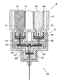
図1に示される薬物送達デバイスは、近位端16から遠位端15まで延びる本体14を含む。遠位端15には、取外し可能なエンドキャップまたはカバー18が設けられる。このエンドキャップ18および本体14の遠位端15はともに働いて、スナップ嵌めまたは形状嵌め連結を提供するので、カバー18を本体14の遠位端15上に嵌めると、キャップと本体の外表面20との間のこの摩擦嵌めによって、カバーが本体から不用意に落下するのを防ぐ。
The drug delivery device shown in FIG. 1 includes a
本体14は、マイクロプロセッサ制御ユニット、電気機械的ドライブトレーン、および少なくとも2つの薬剤リザーバを収容する。エンドキャップまたはカバー18が(図1に示されるように)デバイス10から取り外されると、投薬インターフェース200が本体14の遠位端15に装着され、用量ディスペンサ(例えば、ニードルアセンブリ)がインターフェースに取り付けられる。薬物送達デバイス10を使用して、第2の薬剤(二次薬物化合物)の計算された用量と、第1の薬剤(一次薬物化合物)の可変用量とを、両頭ニードルアセンブリなどの単一のニードルアセンブリを通して投与することができる。
The
ドライブトレーンは、第1および第2の薬剤の用量をそれぞれ排出するために、各カートリッジの栓に圧力をかけてもよい。例えば、ピストンロッドがカートリッジの栓を押して、薬剤の単回用量の所定量を送ってもよい。カートリッジが空のとき、ピストンロッドは完全に本体14の内部に撤回されるので、空のカートリッジを除去し、新しいカートリッジを挿入することができる。
The drive train may apply pressure to the stoppers of each cartridge to drain the first and second drug doses, respectively. For example, a piston rod may push a plug on a cartridge to deliver a predetermined amount of a single dose of drug. When the cartridge is empty, the piston rod is completely retracted into the
制御パネル領域60は、本体14の近位端付近に設けられる。好ましくは、この制御パネル領域60は、組合せ用量を設定し注射するのにユーザが操作することができる、複数のヒューマンインターフェース要素とともに、デジタルディスプレイ80を含む。この配置では、制御パネル領域は、第1の用量設定ボタン62、第2の用量設定ボタン64、および記号「OK」で指定された第3のボタン66を含む。それに加えて、本体の最近位端に沿って、注射ボタン74も設けられる(図1の斜視図では見えない)。薬物送達デバイスのユーザインターフェースは、「メニュー」ボタン、「戻る」ボタン、またはディスプレイの照明のスイッチを入れる「点灯」ボタンなど、追加のボタンを含んでもよい。
The
カートリッジホルダ40は、本体14に取外し可能に取り付けることができ、少なくとも2つのカートリッジ保持器50および52を収容してもよい。各保持器は、ガラスカートリッジなど、1つの薬剤リザーバを収容するように構成される。好ましくは、各カートリッジは異なる薬剤を収容する。
The
それに加えて、カートリッジホルダ40の遠位端では、図1に示される薬物送達デバイスは投薬インターフェース200を含む。図4に関連して記載するように、1つの配置では、この投薬インターフェース200は、カートリッジハウジング40の遠位端42に取外し可能に取り付けられる外側本体212を含む。図1で分かるように、投薬インターフェース200の遠位端214は、好ましくはニードルハブ216を含む。このニードルハブ216は、従来のペン型注射ニードルアセンブリなどの用量ディスペンサを、薬物送達デバイス10に取外し可能に装着することを可能にするように構成してもよい。
In addition, at the distal end of the
デバイスのスイッチがオンにされると、図1に示されるデジタルディスプレイ80が明るくなり、特定のデバイス情報、好ましくはカートリッジホルダ40内に収容された薬剤に関する情報をユーザに提供する。例えば、ユーザには、一次薬剤(薬物A)および二次薬剤(薬物B)の両方に関連する特定の情報が提供される。
When the device is switched on, the
図3に示されるように、第1および第2のカートリッジ保持器50、52は、ヒンジ連結されたカートリッジ保持器であってもよい。これらのヒンジ連結された保持器によって、ユーザがカートリッジにアクセスできるようになる。図3は、第1のヒンジ連結されたカートリッジ保持器50が開位置にある、図1に示されるカートリッジホルダ40の斜視図を示す。図3は、第1の保持器50を開き、それによって第1のカートリッジ90へのアクセスを有することにより、ユーザが第1のカートリッジ90にアクセスする方法を示している。
As shown in FIG. 3, the first and
図1について考察する際に上述したように、投薬インターフェース200は、カートリッジホルダ40の遠位端に連結することができる。図4は、カートリッジホルダ40の遠位端に連結されていない投薬インターフェース200の平面図を示す。インターフェース200とともに使用してもよい用量ディスペンサまたはニードルアセンブリ400も示されており、保護用の外キャップ420内に設けられる。
As discussed above in discussing FIG. 1, the
図5では、図4に示される投薬インターフェース200はカートリッジホルダ40に連結されて示されている。投薬インターフェース200とカートリッジホルダ40との間の軸方向取付け手段48は、スナップロック、スナップ嵌め、スナップリング、キー溝付きスロット、およびかかる連結の組合せを含む、当業者には知られている任意の軸方向取付け手段とすることができる。投薬インターフェースとカートリッジホルダとの間の連結または取付けはまた、コネクタ、止め具、スプライン、リブ、溝、ピップ、クリップ、および類似の設計機構など、特定のハブが適合する薬物送達デバイスのみに取付け可能であることを確保する、追加の機能(図示なし)を含んでもよい。かかる追加の機能は、適切でない補助カートリッジが適合しない注射デバイスに挿入されるのを防ぐ。
In FIG. 5, the
図5はまた、インターフェース200のニードルハブにねじ留めしてもよい、投薬インターフェース200の遠位端に連結されたニードルアセンブリ400および保護カバー420を示す。図6は、図5の投薬インターフェース200上に装着された両頭ニードルアセンブリ400の断面図を示す。
FIG. 5 also shows the
図6に示されるニードルアセンブリ400は両頭針406およびハブ401を含む。両頭針またはカニューレ406は、ニードルハブ401内に固定的に装着される。このニードルハブ401は、その周囲に沿って円周方向の垂下するスリーブ403を有する円板状の要素を含む。このハブ部材401の内壁に沿って、ねじ山404が設けられる。このねじ山404によって、ニードルハブ401を、好ましい一実施形態では遠位ハブに沿って対応する雄ねじ山を備える、投薬インターフェース200上にねじ留めすることができる。ハブ要素401の中央部分には、突出部402が設けられる。この突出部402は、スリーブ部材の反対方向でハブから突出する。両頭針406は、突出部402およびニードルハブ401の中心を通って装着される。この両頭針406は、両頭針の第1のまたは遠位の穿孔端部405が、注射部位(例えば、ユーザの皮膚)を穿孔する注射部材を形成するようにして装着される。
The
同様に、ニードルアセンブリ400の第2のまたは近位の穿孔端部408は、スリーブ403によって同心で取り囲まれるようにして円板の反対側から突出する。1つのニードルアセンブリ構成では、第2のまたは近位の穿孔端部408はスリーブ403よりも短いので、このスリーブはバックスリーブの尖った端部をある程度保護する。図4および5に示される針カバーキャップ420は、ハブ401の外表面403の周りに形状嵌めを提供する。
Similarly, the second or proximal
次に図4〜11を参照して、このインターフェース200の1つの好ましい構成について考察する。この好ましい1つの構成では、このインターフェース200は:
a.外側本体210、
b.第1の内側本体220、
c.第2の内側本体230、
d.第1の穿孔針240、
e.第2の穿孔針250、
f.弁シール260、および、
g.セプタム270、を含む。
With reference now to FIGS. 4-11, one preferred configuration of this
a.
b. First
c. A second
d. First piercing
e. A second piercing
f.
g. A
外側本体210は、本体近位端212および本体遠位端214を含む。外側本体210の近位端212において、連結部材は、投薬インターフェース200をカートリッジホルダ40の遠位端に取り付けるのを可能にするように構成される。好ましくは、連結部材は、投薬インターフェースをカートリッジホルダ40に取外し可能に連結するのを可能にするように構成される。1つの好ましいインターフェース構成では、インターフェース200の近位端は、少なくとも1つの凹部を有する上方に延びる壁218を備えて構成される。例えば、図8から分かるように、上方に延びる壁218は少なくとも1つの第1の凹部217および第2の凹部219を含む。
好ましくは、第1および第2の凹部217、219は、薬物送達デバイス10のカートリッジハウジング40の遠位端近くにある、外向きに突出する部材と協働するようにして、この外側本体壁内に位置する。例えば、カートリッジハウジングのこの外向きに突出する部材48は、図4および5で見られる。第2の同様の突出する部材は、カートリッジハウジングの対向面に設けられる。そのため、カートリッジハウジング40の遠位端の上でインターフェース200を軸方向で滑らせると、外向きに突出する部材は、第1および第2の凹部217、219と協働して、干渉嵌め、形状嵌め、またはスナップロックを形成する。あるいは、当業者であれば認識するように、投薬インターフェースおよびカートリッジハウジング40を軸方向で連結できるようにする、他の任意の類似の連結機構を同様に使用することができる。
Preferably, the first and
外側本体210およびカートリッジホルダ40の遠位端は、カートリッジハウジングの遠位端上に軸方向で滑らせることができる、軸方向で係合するスナップロックまたはスナップ嵌め構成を形成するように作用する。1つの代替構成では、投薬インターフェース200は、不用意な投薬インターフェースの混同を防ぐように、コーディング機能を備えてもよい。即ち、ハブの内側本体は、1つまたは複数の投薬インターフェースの不用意な混同を防ぐように、幾何学的に構成することができる。
The
取付けハブは、投薬インターフェース200の外側本体210の遠位端に設けられる。かかる取付けハブは、ニードルアセンブリに解放可能に連結されるように構成することができる。単なる一例として、この連結手段216は、図6に示されるニードルアセンブリ400など、ニードルアセンブリのニードルハブの内壁表面に沿って設けられる雌ねじ山を係合する雄ねじ山を含んでもよい。スナップロック、ねじによって解放されるスナップロック、バヨネットロック、形状嵌め、または他の類似の連結構成など、代替の解放可能なコネクタも設けることができる。
A mounting hub is provided at the distal end of the
投薬インターフェース200は第1の内側本体220をさらに含む。この内側本体の特定の詳細は図8〜11に示される。好ましくは、この第1の内側本体220は、外側本体210の延びる壁218の内表面215に連結される。より好ましくは、この第1の内側本体220は、リブおよび溝の形状嵌め構成を用いて、外側本体210の内表面に連結される。例えば、図9から分かるように、外側本体210の延びる壁218には第1のリブ213aおよび第2のリブ213bが設けられる。この第1のリブ213aは図10にも示される。これらのリブ213aおよび213bは、外側本体210の壁218の内表面215に沿って位置し、第1の内側本体220の協働する溝224aおよび224bとともに、形状嵌めまたはスナップロック係合を作成する。好ましい構成では、これらの協働する溝224aおよび224bは、第1の内側本体220の外表面222に沿って設けられる。
The
それに加えて、図8〜10で分かるように、第1の内側本体220の近位端付近の近位面226は、近位穿孔端部分244を含む少なくとも第1の近位に位置する穿孔針240を備えて構成することができる。同様に、第1の内側本体220は、近位穿孔端部分254を含む第2の近位に位置する穿孔針250を備えて構成される。第1および第2の針240、250は両方とも、第1の内側本体220の近位面226に堅く装着される。
In addition, as can be seen in FIGS. 8-10, the
好ましくは、この投薬インターフェース200はさらに弁構成を含む。かかる弁構成は、第1および第2のリザーバにそれぞれ収容された第1および第2の薬剤の相互汚染を防ぐように構築することができる。好ましい弁構成はまた、第1および第2の薬剤の逆流と相互汚染を防ぐように構成される。
Preferably, the
1つの好ましいシステムでは、投薬インターフェース200は弁シール260の形態の弁構成を含む。かかる弁シール260は、第2の内側本体230によって画成される定義されたキャビティ231内に設けられて、保持チャンバ280を形成してもよい。好ましくは、キャビティ231は第2の内側本体230の上面に沿って存在する。この弁シールは、第1の流体溝264および第2の流体溝266の両方を画成する上面を含む。例えば、図9は、第1の内側本体220と第2の内側本体230との間に収まっている、弁シール260の位置を示す。注射工程の間、このシール弁260は、第1の経路内の一次薬剤が第2の経路内の二次薬剤へと移動するのを防ぐとともに、第2の経路内の二次薬剤が第1の経路内の一次薬剤へと移動するのも防ぐ助けとなる。好ましくは、このシール弁260は第1の逆止め弁262および第2の逆止め弁268を含む。そのため、第1の逆止め弁262は、第1の流体経路264、例えばシール弁260の溝に沿って移動する流体が、この経路264に逆戻りするのを防ぐ。同様に、第2の逆止め弁268は、第2の流体経路266に沿って移動する流体がこの経路266に逆戻りするのを防ぐ。
In one preferred system, the dispensing
第1および第2の溝264、266はともに、逆止め弁262および268に向かってそれぞれ収束し、結果的に出力流路または保持チャンバ280を提供する。この保持チャンバ280は、第2の内側本体の遠位端と、第1および第2の逆止め弁262、268の両方と、穿孔可能なセプタム270とによって画成される、内側チャンバによって画成される。図示されるように、この穿孔可能なセプタム270は、第2の内側本体230の遠位端部分と、外側本体210のニードルハブによって画成される内表面との間に位置する。
Both the first and
保持チャンバ280はインターフェース200の出口ポートで終端する。この出口ポート290は、好ましくは、インターフェース200のニードルハブの中央に位置し、穿孔可能なシール270を固定位置で維持するのを支援する。そのため、両頭ニードルアセンブリがインターフェース(図6に示される両頭針など)のニードルハブに取り付けられたとき、出口流路によって、両方の薬剤を取り付けられたニードルアセンブリと流体連通させることができる。
The holding
ハブインターフェース200は第2の内側本体230をさらに含む。図9から分かるように、この第2の内側本体230は凹部を画成する上面を有し、弁シール260はこの凹部内に位置する。したがって、インターフェース200が図9に示されるように組み立てられると、第2の内側本体230は、外側本体210の遠位端と第1の内側本体220との間に位置するようになる。第2の内側本体230および外側本体はともに、セプタム270を適所で保持する。内側本体230の遠位端はまた、弁シールの第1の溝264および第2の溝266と流体連通するように構成することができる、キャビティまたは保持チャンバを形成してもよい。
The
薬物送達デバイスの遠位端の上で外側本体210を軸方向で滑らせることで、投薬インターフェース200が複数回用デバイスに取り付けられる。このように、第1の針240と第2の針250との間で、それぞれ第1のカートリッジの一次薬剤および第2のカートリッジの二次薬剤と流体連通させることができる。
The
図11は、図1に示される薬物送達デバイス10のカートリッジホルダ40の遠位端42上に装着された後の投薬インターフェース200を示す。両頭針400もこのインターフェースの遠位端に装着されている。カートリッジホルダ40は、第1の薬剤を収容した第1のカートリッジ、および第2の薬剤を収容した第2のカートリッジを有するものとして示されている。
FIG. 11 shows the dispensing
インターフェース200がカートリッジホルダ40の遠位端の上に最初に装着されると、第1の穿孔針240の近位穿孔端部244は第1のカートリッジ90のセプタムを穿孔し、それによって第1のカートリッジ90の一次薬剤92と流体連通する。第1の穿孔針240の遠位端も、弁シール260によって画成される第1の流体経路溝264と流体連通するようになる。
When the
同様に、第2の穿孔針250の近位穿孔端部254は第2のカートリッジ100のセプタムを穿孔し、それによって第2のカートリッジ100の二次薬剤102と流体連通する。この第2の穿孔針250の遠位端も、弁シール260によって画成される第2の流体経路溝266と流体連通するようになる。
Similarly, the proximal piercing
図11は、薬物送達デバイス10の本体14の遠位端15に連結されるような投薬インターフェース200の好ましい構成を示す。好ましくは、かかる投薬インターフェース200は、薬物送達デバイス10のカートリッジホルダ40に取外し可能に連結される。
FIG. 11 shows a preferred configuration of the dispensing
図11に示されるように、投薬インターフェース200は、カートリッジハウジング40の遠位端に連結される。このカートリッジホルダ40は、一次薬剤92を収容した第1のカートリッジ90、および第2の薬剤102を収容した第2のカートリッジ100を収容するものとして示されている。カートリッジハウジング40に連結されると、投薬インターフェース200は本質的に、第1および第2のカートリッジ90、100から共通の保持チャンバ280までの流体連通経路を提供する機構となる。この保持チャンバ280は、用量ディスペンサと流体連通しているものとして示される。ここで、図示されるように、この用量ディスペンサは両頭ニードルアセンブリ400を含む。図示されるように、両頭ニードルアセンブリの近位端はチャンバ280と流体連通している。
As shown in FIG. 11, the
1つの好ましい構成では、投薬インターフェースは、1つの配向のみで本体に付着するように、即ち一方向でのみ適合されるように構成される。そのため、図11に示されるように、投薬インターフェース200がカートリッジホルダ40に取り付けられたとき、主要な針240のみを第1のカートリッジ90の一次薬剤92と流体連通させるのに使用することができ、インターフェース200をホルダ40に取り付け直し、主要な針240を今度は、第2のカートリッジ100の二次薬剤102と流体連通させるのに使用することを妨げることができる。かかる一方向の連結機構は、2つの薬剤92および102の間で起こり得る相互汚染を低減する助けとすることができる。
In one preferred configuration, the dosing interface is configured to attach to the body in only one orientation, ie, adapted in only one direction. Thus, as shown in FIG. 11, when the
投薬インターフェース200およびニードルアセンブリ400は両方とも、2つのカートリッジ90、100の少なくとも一方からの薬剤を、遠位穿孔端部405から放出する放出チャネルを形成する。図11に示されるように、放出チャネルは、特に、第1および第2の穿孔針240、250、第1および第2の流体溝264、266、保持チャンバ280、および両頭針406の管腔によって形成される。
Both the dispensing
カートリッジ90、100内の薬剤92、102は、通常、例えば2.7mg/mlの濃度で、m−クレゾールなどの防腐剤を含む。薬剤用量が放出チャネルを通してカートリッジ90、100の少なくとも一方から放出される場合、放出チャネル内のm−クレゾール濃度も2.7mg/mlである。しかしながら、時間に伴って、放出チャネル内のm−クレゾール含量は減少することが観察されたので、特にm−クレゾール含量が約1.8mg/mlを下回った場合に、放出チャネルの生物学的健全性は危険に晒される。その際のm−クレゾール含量は、細菌または酵母/菌類の十分な低減を確保するには低すぎることがある。
The
m−クレゾール含量レベルは、放出チャネルを通して流体量をカートリッジ90、100から放出し、それによって放出チャネル内の流体の少なくとも一部を交換することによって、安全レベルまで回復させることができる。デバイスが、例えばユーザが少なくとも一日一回インスリンを注射することによって、一日単位で使用される場合、放出チャネル内の十分な流体交換は恒常的な使用によって確保される。しかしながら、ユーザが2つの異なるデバイスを交互に使用するか、またはデバイスを使用し忘れることなどによって、デバイスが長時間使用されない場合、放出デバイス内のm−クレゾールレベルは、デバイスが次に使用される前には臨界レベルまで下がっていることがある。
The m-cresol content level can be restored to a safe level by releasing the amount of fluid from the
プライミング試験工程を行うことにより、例えばデバイスの任意のボタンを押し下げることによってデバイスを起動させると、またはユーザが注射ボタン74を押し下げることによって流体用量放出工程を開始すると、放出チャネル内の生物学的健全性を確保することができ、それに伴ってユーザ安全性を改善することができる。制御ユニットを用いて送達デバイスを適宜制御する一例について、図12および13を参照して次に記載する。
By performing the priming test process, for example, by activating the device by depressing any button on the device, or when the user initiates the fluid dose release process by depressing the
図12は、図1に示される送達デバイスの制御ユニットの概略図を示す。送達デバイスの本体14は、特に、次の構成要素を含む:
a.制御ユニット510;
b.流体放出用のアクチュエータ520;および、
c.記憶装置530。
FIG. 12 shows a schematic diagram of the control unit of the delivery device shown in FIG. The
a. Control unit 510;
b. An
c.
制御ユニット510はマイクロプロセッサ制御ユニットであり、送達デバイスの機能を制御するように構成される。特に、制御ユニット510は、例えば、カートリッジ90、100の一方から放出チャネルを通して薬剤を放出するために、デバイスのドライブトレーンを作動させるドライブトレーンアクチュエータであってもよい、流体注射用のアクチュエータ520を制御するように構成される。例えば、ユーザが注射ボタン74を押し下げた場合、制御ユニット510は流体用量放出工程を行ってもよく、その間、制御ユニット510はアクチュエータ520を制御してデバイスのドライブトレーンを作動させ、それによって規定の薬剤用量が、カートリッジ90、100の少なくとも一方から放出チャネルを通して放出され、例えば患者に投与される。
Control unit 510 is a microprocessor control unit and is configured to control the function of the delivery device. In particular, the control unit 510 controls an
制御ユニット510はさらに、放出チャネルを通した流体量の最後の放出以降の時間長である、プライミング時間長を決定するように構成され、本例におけるその流体量は、デバイスの放出チャネルの容積以上である。この目的のため、制御ユニット510は、流体用量放出工程または放出チャネルプライミング工程が行われた時間を格納するように構成されるので、この時間を現在時間から減算することによってプライミング時間長を決定することができる。 The control unit 510 is further configured to determine a priming time length, which is the length of time since the last discharge of the fluid volume through the discharge channel, where the fluid volume is greater than or equal to the volume of the discharge channel of the device. It is. For this purpose, the control unit 510 is configured to store the time when the fluid dose release step or the release channel priming step was performed, so that the priming time length is determined by subtracting this time from the current time. be able to.
制御ユニット510はさらに、ユーザが注射ボタン74を押し下げた場合にプライミング試験工程を行うように構成される。プライミング試験工程について図13を参照して次に説明する。
The control unit 510 is further configured to perform a priming test process when the user depresses the
図13は、例示的なプライミング試験工程のフローチャートを示す。ユーザがデバイスの操作要素を、この例では注射ボタン74を操作すると(工程610)、制御ユニット510はプライミング試験工程を開始する(工程612)。工程614で、制御ユニット510は、次式の通り、現在時間Tnowから、流体用量放出工程または放出チャネルプライミング工程を最後に行った時間Tlast_ejectionを減算することによって、プライミング時間長Tprimeを決定する。
Tprime=Tnow−Tlast_ejection (1)
FIG. 13 shows a flowchart of an exemplary priming test process. When the user operates the operating element of the device, in this example the injection button 74 (step 610), the control unit 510 initiates the priming test process (step 612). In
T prime = T now −T last_ejection (1)
次に、プライミング時間長の値を、工程616で、所定のプライミング閾値時間長Tthresholdと比較する。プライミング閾値時間長Tthresholdは、例えば、記憶装置530の変数に格納してもよく、記憶装置530は、例えば、RAM、ROM、ハードドライブ、フラッシュメモリなどであってもよい。例えば、プライミング閾値時間長Tthresholdは48時間の値を有してもよい。
Next, in
プライミング時間長Tprimeがプライミング閾値時間長Tthresholdよりも短い場合、放出チャネル内のm−クレゾール含量は安全レベルのはずなので、放出チャネルの汚染のリスクはほとんどまたはまったくない。したがって、この場合、制御ユニット510は、プライミング試験工程を終了し(工程618)、例えば流体用量放出工程を行うなど、デバイスのさらなる動作の制御を継続する(工程620)。 If the priming time length T prime is shorter than the priming threshold time length T threshold , the m-cresol content in the release channel should be at a safe level so there is little or no risk of contamination of the release channel. Thus, in this case, the control unit 510 ends the priming test process (step 618) and continues to control further operation of the device (step 620), eg, performing a fluid dose release process.
しかしながら、プライミング時間長Tprimeがプライミング閾値時間長Tthresholdを上回る場合、m−クレゾールレベルが臨界レベルまで減少している傾向があるので、放出チャネルが、細菌、酵母、または菌類で汚染されていることがある。この場合、制御ユニット510は、放出チャネルプライミング工程の実行後にのみ、さらなる流体用量放出工程が可能にされる状態にデバイスを設定する。この例では、これは、制御ユニット510が放出チャネルプライミング工程を即座に開始することによって達成されるので(工程622)、この工程は、デバイスのさらなる動作を継続する前に行わなければならない。 However, if the priming time length T prime exceeds the priming threshold time length T threshold , the release channel is contaminated with bacteria, yeast, or fungi because the m-cresol level tends to decrease to a critical level. Sometimes. In this case, the control unit 510 sets the device in a state that allows further fluid dose release steps only after performing the release channel priming step. In this example, this is accomplished by the control unit 510 immediately starting the emission channel priming process (step 622), which must be done before continuing further operation of the device.
放出チャネルプライミング工程の間、制御ユニット510は、所定の最小プライミング量以上である流体量の、放出チャネルを通した放出を強制的に行う(工程624)。最小プライミング量の値は、例えば、記憶装置530の変数に格納してもよい。この例では、最小プライミング量は放出チャネルの総容積に設定される。流体量の放出を強制的に行うため、制御ユニット510は、プライミングの開始を要求するために、例えば、「プライミングが必要!注射ボタンを押してプライミングを行ってください!」などのメッセージをデジタル表示80に表示させてもよい。それによってユーザが注射ボタン74を押し下げた場合、制御ユニット510は、所定量が放出チャネルを通してカートリッジ90、100それぞれから放出されるように、流体放出用のアクチュエータ520を制御する。
During the discharge channel priming step, the control unit 510 forces a discharge through the discharge channel of an amount of fluid that is greater than or equal to a predetermined minimum priming amount (step 624). The value of the minimum priming amount may be stored in a variable of the
プライミングの間に放出チャネルのm−クレゾール含量が回復するので、制御ユニット510は、例えばTlast_ejectionをTnowに設定することによって、プライミング時間長Tprimeをリセットし(工程626)、次に、放出チャネルプライミングおよびプライミング試験工程を終了し(工程628、618)、最後にデバイスのさらなる動作を継続する(工程620)。
As the m-cresol content of the release channel is restored during priming, the control unit 510 resets the priming time length T prime (step 626), for example by setting T last_ejection to T now (step 626), and then the release. The channel priming and priming test process is terminated (
本発明の過程において、m−クレゾールを含有する薬剤の生物学的健全性をどのようにして保存できるかを決定するため、多くの実験を行った。これらの実験について以下に記載する: In the course of the present invention, a number of experiments were conducted to determine how the biological health of drugs containing m-cresol can be preserved. These experiments are described below:
第1の実験:
第1の実験では、生物学的健全性を確保するのに必要な最小m−クレゾール濃度を決定した。
First experiment:
In the first experiment, the minimum m-cresol concentration required to ensure biological health was determined.
2.7mg/ml〜1.5mg/mlのm−クレゾール濃度を有する試験溶液に、異なる細菌および菌類/酵母の接種材料を接種し、28日間貯蔵した。試験中、試験溶液の細菌および菌類/酵母の母集団を繰り返し分析した。一例として、1.8mg/mlの試験溶液に関する結果を表2に示す。 Test solutions with m-cresol concentrations from 2.7 mg / ml to 1.5 mg / ml were inoculated with different bacterial and fungal / yeast inoculum and stored for 28 days. During the test, the bacterial and fungal / yeast populations of the test solution were repeatedly analyzed. As an example, the results for the 1.8 mg / ml test solution are shown in Table 2.
表2に示される1.8mg/mlのm−クレゾール試験溶液に対する分析を、別のm−クレゾール含量を有する試験溶液に対しても行った。次に、結果をPh.Eur.およびUSP基準と比較して、どのm−クレゾール含量がこれらの基準を満たすのに十分であるかを決定した。その結果の概要を表3に示す: Analysis for the 1.8 mg / ml m-cresol test solution shown in Table 2 was also performed for test solutions with different m-cresol contents. Next, the results are shown in Ph. Eur. And compared to USP criteria, it was determined which m-cresol content was sufficient to meet these criteria. A summary of the results is shown in Table 3:
表3は、1.5mg/ml以上のすべてのm−クレゾール含量に関して、USP基準が満たされていることを示している。Ph.Eur.基準Aは、少なくとも2.1mg/ml以上、またはさらには1.8mg/ml以上のすべてのm−クレゾール含量に関して満たされている。 Table 3 shows that USP criteria are met for all m-cresol content above 1.5 mg / ml. Ph. Eur. Criterion A is met for all m-cresol content of at least 2.1 mg / ml or more, or even 1.8 mg / ml or more.
したがって、この実験から、2.1mg/mlまたはさらには1.8mg/mlのm−クレゾール含量は依然として、Ph.Eur.基準AおよびUSP基準の両方を十分に満たすものと結論付けられた。 Therefore, from this experiment, an m-cresol content of 2.1 mg / ml or even 1.8 mg / ml is still Ph. Eur. It was concluded that both criteria A and USP criteria were fully met.
第2の実験:
第2の実験では、使用中薬剤安定性、即ち時間に伴う放出チャネル内における薬剤量のm−クレゾール含量について分析した。
Second experiment:
In a second experiment, the drug stability during use, ie the m-cresol content of the drug amount in the release channel with time, was analyzed.
第2の実験に対して、
m−クレゾール2.7mg/ml、
リキシセナチド(AVE1101)400μg/ml、および
インスリングラルギン(HOE901)100U/mlを含む第1の水性試験溶液と、
m−クレゾール2.7mg/ml、および
インスリングラルギン(HOE901)100U/mlを含む第2の水性試験溶液とを提供した。特に、それぞれの試験溶液を収容する、図2に示されるカートリッジ90のような複数のカートリッジを、第1および第2の試験溶液両方に対して提供した。
For the second experiment,
m-cresol 2.7 mg / ml,
A first aqueous test solution comprising lixisenatide (AVE1101) 400 μg / ml and insulin glargine (HOE901) 100 U / ml;
A second aqueous test solution containing 2.7 mg / ml m-cresol and 100 U / ml insulin glargine (HOE901) was provided. In particular, a plurality of cartridges, such as
さらに、図9に示される投薬インターフェース200のような複数の投薬インターフェースを、第1および第2の試験溶液両方に対して提供した。各投薬インターフェースは、図6に示されるニードルアセンブリ400のようなニードルアセンブリに連結した。各投薬インターフェースの死空間は20μlであった。
In addition, multiple dosing interfaces, such as the
第1および第2の試験溶液はそれぞれ、毎回それぞれの溶液20μlの量がそれぞれの投薬インターフェース内に残るようにして、それぞれの投薬インターフェースを通して洗い流した。投薬インターフェース、および参照として第1および第2の試験溶液両方に対する複数の充填済みカートリッジを、次に、14日間の最大期間にわたってインキュベータ内に収納した。 Each of the first and second test solutions was flushed through each dosing interface, leaving an amount of 20 μl of each solution in each dosing interface each time. The dosing interface and multiple filled cartridges for both the first and second test solutions as a reference were then housed in an incubator for a maximum period of 14 days.
実験の開始時(T0)、ならびに5日後(T5)、10日後(T10)、および14日後(T14)に、第1および第2の試験溶液両方について、一度に1つの投薬インターフェースおよび1つのカートリッジをインキュベータから取り出し、それぞれの投薬インターフェースおよびカートリッジ内の試験溶液のm−クレゾール含量を分析した。 One dosing interface and one cartridge at a time for both the first and second test solutions at the start of the experiment (T0) and after 5 days (T5), 10 days (T10), and 14 days (T14) Were removed from the incubator and analyzed for the m-cresol content of the test solution in each dosing interface and cartridge.
表4は、投薬インターフェース(投薬インターフェース)およびカートリッジ(参照)内からの、試験溶液に対するm−クレゾール分析の結果を要約している。 Table 4 summarizes the results of m-cresol analysis for the test solution from within the dosing interface (dosing interface) and cartridge (reference).
カートリッジ内からの、即ち投薬インターフェース材料と接触していなかった溶液からの参照溶液に関する結果は、2.7mg/mlという一定のm−クレゾールレベルを示している。エージング、UV光などによる自然なm−クレゾールの減少は、14日間の最大試験期間に関して、無視できることが判明した。 The results for the reference solution from within the cartridge, ie from the solution that was not in contact with the dosing interface material, show a constant m-cresol level of 2.7 mg / ml. Natural m-cresol reduction due to aging, UV light, etc. was found to be negligible for a maximum test period of 14 days.
それとは対照的に、投薬インターフェース内からの試験溶液に関する結果は、第1および第2の試験溶液両方に対してm−クレゾールレベルの低下を示している。したがって、m−クレゾールレベルのこの減少は、溶液と投薬インターフェース材料の接触に起因している。 In contrast, the results for the test solution from within the dosing interface indicate a decrease in m-cresol levels for both the first and second test solutions. Thus, this decrease in m-cresol levels is due to contact between the solution and the dosing interface material.
インキュベータ内での5〜10日間の時間後、投薬インターフェース内の試験溶液のm−クレゾール含量は2.1mg/mlの含量未満に低下したが、これは第1の実験によれば、依然として生物学的健全性の安全レベルであると仮定される。したがって、m−クレゾールレベルを再び上昇させるため、デバイスの放出チャネルは、5〜10日間の最大時間後に新しい流体で洗い流すべきである。したがって、プライミング閾値時間長は、24時間〜10日間、好ましくは36時間〜5日間の範囲から選択されるのが好ましい。 After 5-10 days in the incubator, the m-cresol content of the test solution in the dosing interface dropped below a content of 2.1 mg / ml, which is still biological according to the first experiment. Is assumed to be a safe level of sanity. Therefore, in order to raise the m-cresol level again, the release channel of the device should be flushed with fresh fluid after a maximum time of 5-10 days. Therefore, the priming threshold time length is preferably selected from the range of 24 hours to 10 days, preferably 36 hours to 5 days.
本明細書で使用する用語「薬物」または「薬剤」は、少なくとも1つの薬学的に活性な化合物を含む医薬製剤を意味し、
ここで、一実施形態において、薬学的に活性な化合物は、最大1500Daまでの分子量を有し、および/または、ペプチド、タンパク質、多糖類、ワクチン、DNA、RNA、酵素、抗体もしくはそのフラグメント、ホルモンもしくはオリゴヌクレオチド、または上述の薬学的に活性な化合物の混合物であり、
ここで、さらなる実施形態において、薬学的に活性な化合物は、糖尿病、または糖尿病性網膜症などの糖尿病関連の合併症、深部静脈血栓塞栓症または肺血栓塞栓症などの血栓塞栓症、急性冠症候群(ACS)、狭心症、心筋梗塞、がん、黄斑変性症、炎症、枯草熱、アテローム性動脈硬化症および/または関節リウマチの処置および/または予防に有用であり、
ここで、さらなる実施形態において、薬学的に活性な化合物は、糖尿病または糖尿病性網膜症などの糖尿病に関連する合併症の処置および/または予防のための少なくとも1つのペプチドを含み、
ここで、さらなる実施形態において、薬学的に活性な化合物は、少なくとも1つのヒトインスリンもしくはヒトインスリン類似体もしくは誘導体、グルカゴン様ペプチド(GLP−1)もしくはその類似体もしくは誘導体、またはエキセンジン−3もしくはエキセンジン−4もしくはエキセンジン−3もしくはエキセンジン−4の類似体もしくは誘導体を含む。
The term “drug” or “agent” as used herein means a pharmaceutical formulation comprising at least one pharmaceutically active compound,
Here, in one embodiment, the pharmaceutically active compound has a molecular weight of up to 1500 Da and / or a peptide, protein, polysaccharide, vaccine, DNA, RNA, enzyme, antibody or fragment thereof, hormone Or an oligonucleotide, or a mixture of the above-mentioned pharmaceutically active compounds,
Here, in a further embodiment, the pharmaceutically active compound is diabetic or diabetes related complications such as diabetic retinopathy, thromboembolism such as deep vein thromboembolism or pulmonary thromboembolism, acute coronary syndrome (ACS), useful for the treatment and / or prevention of angina pectoris, myocardial infarction, cancer, macular degeneration, inflammation, hay fever, atherosclerosis and / or rheumatoid arthritis,
Here, in a further embodiment, the pharmaceutically active compound comprises at least one peptide for the treatment and / or prevention of diabetes-related complications such as diabetes or diabetic retinopathy,
Here, in a further embodiment, the pharmaceutically active compound is at least one human insulin or human insulin analogue or derivative, glucagon-like peptide (GLP-1) or analogue or derivative thereof, or exendin-3 or exendin -4 or exendin-3 or analogs or derivatives of exendin-4.
インスリン類似体は、例えば、Gly(A21),Arg(B31),Arg(B32)ヒトインスリン;Lys(B3),Glu(B29)ヒトインスリン;Lys(B28),Pro(B29)ヒトインスリン;Asp(B28)ヒトインスリン;B28位におけるプロリンがAsp、Lys、Leu、Val、またはAlaで置き換えられており、B29位において、LysがProで置き換えられていてもよいヒトインスリン;Ala(B26)ヒトインスリン;Des(B28−B30)ヒトインスリン;Des(B27)ヒトインスリン、およびDes(B30)ヒトインスリンである。 Insulin analogues include, for example, Gly (A21), Arg (B31), Arg (B32) human insulin; Lys (B3), Glu (B29) human insulin; Lys (B28), Pro (B29) human insulin; B28) human insulin; proline at position B28 is replaced with Asp, Lys, Leu, Val, or Ala, and at position B29, human insulin where Lys may be replaced with Pro; Ala (B26) human insulin; Des (B28-B30) human insulin; Des (B27) human insulin, and Des (B30) human insulin.
インスリン誘導体は、例えば、B29−N−ミリストイル−des(B30)ヒトインスリン;B29−N−パルミトイル−des(B30)ヒトインスリン;B29−N−ミリストイルヒトインスリン;B29−N−パルミトイルヒトインスリン;B28−N−ミリストイルLysB28ProB29ヒトインスリン;B28−N−パルミトイル−LysB28ProB29ヒトインスリン;B30−N−ミリストイル−ThrB29LysB30ヒトインスリン;B30−N−パルミトイル−ThrB29LysB30ヒトインスリン;B29−N−(N−パルミトイル−γ−グルタミル)−des(B30)ヒトインスリン;B29−N−(N−リトコリル−γ−グルタミル)−des(B30)ヒトインスリン;B29−N−(ω−カルボキシヘプタデカノイル)−des(B30)ヒトインスリン、およびB29−N−(ω−カルボキシヘプタデカノイル)ヒトインスリンである。 Insulin derivatives include, for example, B29-N-myristoyl-des (B30) human insulin; B29-N-palmitoyl-des (B30) human insulin; B29-N-myristoyl human insulin; B29-N-palmitoyl human insulin; B28- N-myristoyl LysB28ProB29 human insulin; B28-N-palmitoyl-LysB28ProB29 human insulin; B30-N-myristoyl-ThrB29LysB30 human insulin; B30-N-palmitoyl-ThrB29LysB30 human insulin; B29-N- (N-palmitoyl) -Des (B30) human insulin; B29-N- (N-ritocryl-γ-glutamyl) -des (B30) human insulin; B29-N- (ω-ca Bo carboxymethyl hepta decanoyl) -des (B30) human insulin, and B29-N- (ω- carboxyheptadecanoyl) human insulin.
エキセンジン−4は、例えば、H−His−Gly−Glu−Gly−Thr−Phe−Thr−Ser−Asp−Leu−Ser−Lys−Gln−Met−Glu−Glu−Glu−Ala−Val−Arg−Leu−Phe−Ile−Glu−Trp−Leu−Lys−Asn−Gly−Gly−Pro−Ser−Ser−Gly−Ala−Pro−Pro−Pro−Ser−NH2配列のペプチドであるエキセンジン−4(1−39)を意味する。 Exendin-4 is, for example, H-His-Gly-Glu-Gly-Thr-Phe-Thr-Ser-Asp-Leu-Ser-Lys-Gln-Met-Glu-Glu-Glu-Ala-Val-Arg-Leu Exendin-4 (1-39, which is a peptide of the sequence -Phe-Ile-Glu-Trp-Leu-Lys-Asn-Gly-Gly-Pro-Ser-Ser-Gly-Ala-Pro-Pro-Pro-Ser-NH2 ).
エキセンジン−4誘導体は、例えば、以下のリストの化合物:
H−(Lys)4−desPro36,desPro37エキセンジン−4(1−39)−NH2、
H−(Lys)5−desPro36,desPro37エキセンジン−4(1−39)−NH2、
desPro36[Asp28]エキセンジン−4(1−39)、
desPro36[IsoAsp28]エキセンジン−4(1−39)、
desPro36[Met(O)14,Asp28]エキセンジン−4(1−39)、
desPro36[Met(O)14,IsoAsp28]エキセンジン−(1−39)、
desPro36[Trp(O2)25,Asp28]エキセンジン−4(1−39)、
desPro36[Trp(O2)25,IsoAsp28]エキセンジン−4(1−39)、
desPro36[Met(O)14,Trp(O2)25,Asp28]エキセンジン−4(1−39)、
desPro36[Met(O)14Trp(O2)25,IsoAsp28]エキセンジン−4(1−39);または
desPro36[Asp28]エキセンジン−4(1−39)、
desPro36[IsoAsp28]エキセンジン−4(1−39)、
desPro36[Met(O)14,Asp28]エキセンジン−4(1−39)、
desPro36[Met(O)14,IsoAsp28]エキセンジン−(1−39)、
desPro36[Trp(O2)25,Asp28]エキセンジン−4(1−39)、
desPro36[Trp(O2)25,IsoAsp28]エキセンジン−4(1−39)、
desPro36[Met(O)14,Trp(O2)25,Asp28]エキセンジン−4(1−39)、
desPro36[Met(O)14,Trp(O2)25,IsoAsp28]エキセンジン−4(1−39)、
(ここで、基−Lys6−NH2が、エキセンジン−4誘導体のC−末端に結合していてもよい);
Exendin-4 derivatives are, for example, compounds of the following list:
H- (Lys) 4-desPro36, desPro37 exendin-4 (1-39) -NH2,
H- (Lys) 5-desPro36, desPro37 exendin-4 (1-39) -NH2,
desPro36 [Asp28] exendin-4 (1-39),
desPro36 [IsoAsp28] exendin-4 (1-39),
desPro36 [Met (O) 14, Asp28] exendin-4 (1-39),
desPro36 [Met (O) 14, IsoAsp28] Exendin- (1-39),
desPro36 [Trp (O2) 25, Asp28] exendin-4 (1-39),
desPro36 [Trp (O2) 25, IsoAsp28] exendin-4 (1-39),
desPro36 [Met (O) 14, Trp (O2) 25, Asp28] exendin-4 (1-39),
desPro36 [Met (O) 14Trp (O2) 25, IsoAsp28] Exendin-4 (1-39); or desPro36 [Asp28] Exendin-4 (1-39),
desPro36 [IsoAsp28] exendin-4 (1-39),
desPro36 [Met (O) 14, Asp28] exendin-4 (1-39),
desPro36 [Met (O) 14, IsoAsp28] Exendin- (1-39),
desPro36 [Trp (O2) 25, Asp28] exendin-4 (1-39),
desPro36 [Trp (O2) 25, IsoAsp28] exendin-4 (1-39),
desPro36 [Met (O) 14, Trp (O2) 25, Asp28] exendin-4 (1-39),
desPro36 [Met (O) 14, Trp (O 2) 25, IsoAsp 28] Exendin-4 (1-39),
(Wherein the group -Lys6-NH2 may be attached to the C-terminus of the exendin-4 derivative);
または、以下の配列のエキセンジン−4誘導体:
H−(Lys)6−desPro36[Asp28]エキセンジン−4(1−39)−Lys6−NH2、
desAsp28Pro36,Pro37,Pro38エキセンジン−4(1−39)−NH2、
H−(Lys)6−desPro36,Pro38[Asp28]エキセンジン−4(1−39)−NH2、
H−Asn−(Glu)5desPro36,Pro37,Pro38[Asp28]エキセンジン−4(1−39)−NH2、
desPro36,Pro37,Pro38[Asp28]エキセンジン−4(1−39)−(Lys)6−NH2、
H−(Lys)6−desPro36,Pro37,Pro38[Asp28]エキセンジン−4(1−39)−(Lys)6−NH2、
H−Asn−(Glu)5−desPro36,Pro37,Pro38[Asp28]エキセンジン−4(1−39)−(Lys)6−NH2、
H−(Lys)6−desPro36[Trp(O2)25,Asp28]エキセンジン−4(1−39)−Lys6−NH2、
H−desAsp28Pro36,Pro37,Pro38[Trp(O2)25]エキセンジン−4(1−39)−NH2、
H−(Lys)6−desPro36,Pro37,Pro38[Trp(O2)25,Asp28]エキセンジン−4(1−39)−NH2、
H−Asn−(Glu)5−desPro36,Pro37,Pro38[Trp(O2)25,Asp28]エキセンジン−4(1−39)−NH2、
desPro36,Pro37,Pro38[Trp(O2)25,Asp28]エキセンジン−4(1−39)−(Lys)6−NH2、
H−(Lys)6−desPro36,Pro37,Pro38[Trp(O2)25,Asp28]エキセンジン−4(1−39)−(Lys)6−NH2、
H−Asn−(Glu)5−desPro36,Pro37,Pro38[Trp(O2)25,Asp28]エキセンジン−4(1−39)−(Lys)6−NH2、
H−(Lys)6−desPro36[Met(O)14,Asp28]エキセンジン−4(1−39)−Lys6−NH2、
desMet(O)14,Asp28Pro36,Pro37,Pro38エキセンジン−4(1−39)−NH2、
H−(Lys)6−desPro36,Pro37,Pro38[Met(O)14,Asp28]エキセンジン−4(1−39)−NH2、
H−Asn−(Glu)5−desPro36,Pro37,Pro38[Met(O)14,Asp28]エキセンジン−4(1−39)−NH2;
desPro36,Pro37,Pro38[Met(O)14,Asp28]エキセンジン−4(1−39)−(Lys)6−NH2、
H−(Lys)6−desPro36,Pro37,Pro38[Met(O)14,Asp28]エキセンジン−4(1−39)−(Lys)6−NH2、
H−Asn−(Glu)5desPro36,Pro37,Pro38[Met(O)14,Asp28]エキセンジン−4(1−39)−(Lys)6−NH2、
H−Lys6−desPro36[Met(O)14,Trp(O2)25,Asp28]エキセンジン−4(1−39)−Lys6−NH2、
H−desAsp28,Pro36,Pro37,Pro38[Met(O)14,Trp(O2)25]エキセンジン−4(1−39)−NH2、
H−(Lys)6−desPro36,Pro37,Pro38[Met(O)14,Asp28]エキセンジン−4(1−39)−NH2、
H−Asn−(Glu)5−desPro36,Pro37,Pro38[Met(O)14,Trp(O2)25,Asp28]エキセンジン−4(1−39)−NH2、
desPro36,Pro37,Pro38[Met(O)14,Trp(O2)25,Asp28]エキセンジン−4(1−39)−(Lys)6−NH2、
H−(Lys)6−desPro36,Pro37,Pro38[Met(O)14,Trp(O2)25,Asp28]エキセンジン−4(S1−39)−(Lys)6−NH2、
H−Asn−(Glu)5−desPro36,Pro37,Pro38[Met(O)14,Trp(O2)25,Asp28]エキセンジン−4(1−39)−(Lys)6−NH2;
または前述のいずれか1つのエキセンジン−4誘導体の薬学的に許容される塩もしくは溶媒和化合物
から選択される。
Or an exendin-4 derivative of the following sequence:
H- (Lys) 6-desPro36 [Asp28] Exendin-4 (1-39) -Lys6-NH2,
desAsp28Pro36, Pro37, Pro38 exendin-4 (1-39) -NH2,
H- (Lys) 6-desPro36, Pro38 [Asp28] Exendin-4 (1-39) -NH2,
H-Asn- (Glu) 5desPro36, Pro37, Pro38 [Asp28] Exendin-4 (1-39) -NH2,
desPro36, Pro37, Pro38 [Asp28] Exendin-4 (1-39)-(Lys) 6-NH2,
H- (Lys) 6-desPro36, Pro37, Pro38 [Asp28] Exendin-4 (1-39)-(Lys) 6-NH2,
H-Asn- (Glu) 5-desPro36, Pro37, Pro38 [Asp28] Exendin-4 (1-39)-(Lys) 6-NH2,
H- (Lys) 6-desPro36 [Trp (O2) 25, Asp28] exendin-4 (1-39) -Lys6-NH2,
H-desAsp28Pro36, Pro37, Pro38 [Trp (O2) 25] exendin-4 (1-39) -NH2,
H- (Lys) 6-desPro36, Pro37, Pro38 [Trp (O2) 25, Asp28] exendin-4 (1-39) -NH2,
H-Asn- (Glu) 5-desPro36, Pro37, Pro38 [Trp (O2) 25, Asp28] exendin-4 (1-39) -NH2,
desPro36, Pro37, Pro38 [Trp (O2) 25, Asp28] exendin-4 (1-39)-(Lys) 6-NH2,
H- (Lys) 6-desPro36, Pro37, Pro38 [Trp (O2) 25, Asp28] exendin-4 (1-39)-(Lys) 6-NH2,
H-Asn- (Glu) 5-desPro36, Pro37, Pro38 [Trp (O2) 25, Asp28] exendin-4 (1-39)-(Lys) 6-NH2,
H- (Lys) 6-desPro36 [Met (O) 14, Asp28] exendin-4 (1-39) -Lys6-NH2,
desMet (O) 14, Asp28Pro36, Pro37, Pro38 exendin-4 (1-39) -NH2,
H- (Lys) 6-desPro36, Pro37, Pro38 [Met (O) 14, Asp28] exendin-4 (1-39) -NH2,
H-Asn- (Glu) 5-desPro36, Pro37, Pro38 [Met (O) 14, Asp28] exendin-4 (1-39) -NH2;
desPro36, Pro37, Pro38 [Met (O) 14, Asp28] Exendin-4 (1-39)-(Lys) 6-NH2,
H- (Lys) 6-desPro36, Pro37, Pro38 [Met (O) 14, Asp28] exendin-4 (1-39)-(Lys) 6-NH2,
H-Asn- (Glu) 5desPro36, Pro37, Pro38 [Met (O) 14, Asp28] Exendin-4 (1-39)-(Lys) 6-NH2,
H-Lys6-desPro36 [Met (O) 14, Trp (O2) 25, Asp28] Exendin-4 (1-39) -Lys6-NH2,
H-desAsp28, Pro36, Pro37, Pro38 [Met (O) 14, Trp (O2) 25] exendin-4 (1-39) -NH2,
H- (Lys) 6-desPro36, Pro37, Pro38 [Met (O) 14, Asp28] exendin-4 (1-39) -NH2,
H-Asn- (Glu) 5-desPro36, Pro37, Pro38 [Met (O) 14, Trp (O2) 25, Asp28] Exendin-4 (1-39) -NH2,
desPro36, Pro37, Pro38 [Met (O) 14, Trp (O2) 25, Asp28] Exendin-4 (1-39)-(Lys) 6-NH2,
H- (Lys) 6-desPro36, Pro37, Pro38 [Met (O) 14, Trp (O2) 25, Asp28] Exendin-4 (S1-39)-(Lys) 6-NH2,
H-Asn- (Glu) 5-desPro36, Pro37, Pro38 [Met (O) 14, Trp (O2) 25, Asp28] Exendin-4 (1-39)-(Lys) 6-NH2;
Or a pharmaceutically acceptable salt or solvate of any one of the aforementioned exendin-4 derivatives.
ホルモンは、例えば、ゴナドトロピン(フォリトロピン、ルトロピン、コリオンゴナドトロピン、メノトロピン)、ソマトロピン(ソマトロピン)、デスモプレシン、テルリプレシン、ゴナドレリン、トリプトレリン、ロイプロレリン、ブセレリン、ナファレリン、ゴセレリンなどの、Rote Liste、2008年版、50章に列挙されている脳下垂体ホルモンまたは視床下部ホルモンまたは調節性活性ペプチドおよびそれらのアンタゴニストである。 The hormones include, for example, gonadotropin (folytropin, lutropin, corion gonadotropin, menotropin), somatropin (somatropin), desmopressin, telluripressin, gonadorelin, triptorelin, leuprorelin, buserelin, nafarelin, goserelin, etc. Rote Liste, 2008 Pituitary hormones or hypothalamic hormones or regulatory active peptides and antagonists thereof.
多糖類としては、例えば、グルコサミノグリカン、ヒアルロン酸、ヘパリン、低分子量ヘパリン、もしくは超低分子量ヘパリン、またはそれらの誘導体、または上述の多糖類の硫酸化形態、例えば、ポリ硫酸化形態、および/または、薬学的に許容されるそれらの塩がある。ポリ硫酸化低分子量ヘパリンの薬学的に許容される塩の例としては、エノキサパリンナトリウムがある。 Polysaccharides include, for example, glucosaminoglycan, hyaluronic acid, heparin, low molecular weight heparin, or ultra low molecular weight heparin, or derivatives thereof, or sulfated forms of the above-mentioned polysaccharides, such as polysulfated forms, and Or a pharmaceutically acceptable salt thereof. An example of a pharmaceutically acceptable salt of polysulfated low molecular weight heparin is sodium enoxaparin.
抗体は、基本構造を共有する免疫グロブリンとしても知られている球状血漿タンパク質(約150kDa)である。これらは、アミノ酸残基に付加された糖鎖を有するので、糖タンパク質である。各抗体の基本的な機能単位は免疫グロブリン(Ig)単量体(1つのIg単位のみを含む)であり、分泌型抗体はまた、IgAなどの2つのIg単位を有する二量体、硬骨魚のIgMのような4つのIg単位を有する四量体、または哺乳動物のIgMのように5つのIg単位を有する五量体でもあり得る。 Antibodies are globular plasma proteins (about 150 kDa), also known as immunoglobulins that share a basic structure. These are glycoproteins because they have sugar chains attached to amino acid residues. The basic functional unit of each antibody is an immunoglobulin (Ig) monomer (including only one Ig unit), and the secretory antibody is also a dimer having two Ig units such as IgA, teleost It can also be a tetramer with 4 Ig units, such as IgM, or a pentamer with 5 Ig units, like mammalian IgM.
Ig単量体は、4つのポリペプチド鎖、即ち、システイン残基間のジスルフィド結合によって結合された2つの同一の重鎖および2本の同一の軽鎖から構成される「Y」字型の分子である。それぞれの重鎖は約440アミノ酸長であり、それぞれの軽鎖は約220アミノ酸長である。重鎖および軽鎖はそれぞれ、これらの折り畳み構造を安定化させる鎖内ジスルフィド結合を含む。それぞれの鎖は、Igドメインと呼ばれる構造ドメインから構成される。これらのドメインは約70〜110個のアミノ酸を含み、そのサイズおよび機能に基づいて異なるカテゴリー(例えば、可変即ちV、および定常即ちC)に分類される。これらは、2つのβシートが、保存されたシステインと他の荷電アミノ酸との間の相互作用によって一緒に保持される「サンドイッチ」形状を作り出す特徴的な免疫グロブリン折り畳み構造を有する。 An Ig monomer is a “Y” -shaped molecule composed of four polypeptide chains, two identical heavy chains and two identical light chains joined by a disulfide bond between cysteine residues. It is. Each heavy chain is about 440 amino acids long and each light chain is about 220 amino acids long. Heavy and light chains each contain intrachain disulfide bonds that stabilize these folded structures. Each chain is composed of structural domains called Ig domains. These domains contain about 70-110 amino acids and are classified into different categories (eg, variable or V, and constant or C) based on their size and function. They have a characteristic immunoglobulin fold that creates a “sandwich” shape in which two β-sheets are held together by the interaction between conserved cysteines and other charged amino acids.
α、δ、ε、γおよびμで表される5種類の哺乳類Ig重鎖が存在する。存在する重鎖の種類により抗体のアイソタイプが定義され、これらの鎖はそれぞれ、IgA、IgD、IgE、IgGおよびIgM抗体中に見出される。 There are five types of mammalian Ig heavy chains represented by α, δ, ε, γ and μ. The type of heavy chain present defines the isotype of the antibody, and these chains are found in IgA, IgD, IgE, IgG, and IgM antibodies, respectively.
異なる重鎖はサイズおよび組成が異なり、αおよびγは約450個のアミノ酸を含み、δは約500個のアミノ酸を含み、μおよびεは約550個のアミノ酸を有する。各重鎖は、2つの領域、即ち定常領域(CH)と可変領域(VH)を有する。1つの種において、定常領域は、同じアイソタイプのすべての抗体で本質的に同一であるが、異なるアイソタイプの抗体では異なる。重鎖γ、α、およびδは、3つのタンデム型のIgドメインと、可撓性を加えるためのヒンジ領域とから構成される定常領域を有し、重鎖μおよびεは、4つの免疫グロブリン・ドメインから構成される定常領域を有する。重鎖の可変領域は、異なるB細胞によって産生された抗体では異なるが、単一B細胞またはB細胞クローンによって産生された抗体すべてについては同じである。各重鎖の可変領域は、約110アミノ酸長であり、単一のIgドメインから構成される。 Different heavy chains differ in size and composition, α and γ contain about 450 amino acids, δ contain about 500 amino acids, and μ and ε have about 550 amino acids. Each heavy chain has two regions: a constant region (CH) and a variable region (VH). In one species, the constant region is essentially the same for all antibodies of the same isotype, but different for antibodies of different isotypes. Heavy chains γ, α, and δ have a constant region composed of three tandem Ig domains and a hinge region to add flexibility, and heavy chains μ and ε are four immunoglobulins -It has a constant region composed of domains. The variable region of the heavy chain is different for antibodies produced by different B cells, but is the same for all antibodies produced by a single B cell or B cell clone. The variable region of each heavy chain is approximately 110 amino acids long and is composed of a single Ig domain.
哺乳類では、λおよびκで表される2種類の免疫グロブリン軽鎖がある。軽鎖は2つの連続するドメイン、即ち1つの定常ドメイン(CL)および1つの可変ドメイン(VL)を有する。軽鎖のおおよその長さは、211〜217個のアミノ酸である。各抗体は、常に同一である2本の軽鎖を有し、哺乳類の各抗体につき、軽鎖κまたはλの1つのタイプのみが存在する。 In mammals, there are two types of immunoglobulin light chains, denoted λ and κ. The light chain has two consecutive domains, one constant domain (CL) and one variable domain (VL). The approximate length of the light chain is 211-217 amino acids. Each antibody has two light chains that are always identical, and there is only one type of light chain κ or λ for each mammalian antibody.
すべての抗体の一般的な構造は非常に類似しているが、所与の抗体の固有の特性は、上記で詳述したように、可変(V)領域によって決定される。より具体的には、各軽鎖(VL)について3つおよび重鎖(HV)に3つの可変ループが、抗原との結合、即ちその抗原特異性に関与する。これらのループは、相補性決定領域(CDR)と呼ばれる。VHドメインおよびVLドメインの両方からのCDRが抗原結合部位に寄与するので、最終的な抗原特異性を決定するのは重鎖と軽鎖の組合せであり、どちらか単独ではない。 Although the general structure of all antibodies is very similar, the unique properties of a given antibody are determined by the variable (V) region, as detailed above. More specifically, three variable loops for each light chain (VL) and three variable loops for heavy chain (HV) are involved in antigen binding, ie, its antigen specificity. These loops are called complementarity determining regions (CDRs). Since CDRs from both the VH and VL domains contribute to the antigen binding site, it is the combination of heavy and light chains that determines the final antigen specificity, not either alone.
「抗体フラグメント」は、上記で定義した少なくとも1つの抗原結合フラグメントを含み、そのフラグメントが由来する完全抗体と本質的に同じ機能および特異性を示す。パパインによる限定的なタンパク質消化は、Igプロトタイプを3つのフラグメントに切断する。1つの完全なL鎖および約半分のH鎖をそれぞれが含む2つの同一のアミノ末端フラグメントが、抗原結合フラグメント(Fab)である。サイズが同等であるが、鎖間ジスルフィド結合を有する両方の重鎖の半分の位置でカルボキシル末端を含む第3のフラグメントは、結晶可能なフラグメント(Fc)である。Fcは、炭水化物、相補結合部位、およびFcR結合部位を含む。限定的なペプシン消化により、Fab片とH−H鎖間ジスルフィド結合を含むヒンジ領域の両方を含む単一のF(ab’)2フラグメントが得られる。F(ab’)2は、抗原結合に対して二価である。F(ab’)2のジスルフィド結合は、Fab’を得るために切断することができる。さらに、重鎖および軽鎖の可変領域は、縮合して単鎖可変フラグメント(scFv)を形成することもできる。 “Antibody fragments” comprise at least one antigen-binding fragment as defined above and exhibit essentially the same function and specificity as the complete antibody from which the fragment is derived. Limited protein digestion with papain cleaves the Ig prototype into three fragments. Two identical amino terminal fragments, each containing one complete light chain and about half the heavy chain, are antigen-binding fragments (Fabs). A third fragment that is equivalent in size but contains a carboxyl terminus at half the positions of both heavy chains with interchain disulfide bonds is a crystallizable fragment (Fc). Fc includes a carbohydrate, a complementary binding site, and an FcR binding site. Limited pepsin digestion yields a single F (ab ') 2 fragment containing both the Fab piece and the hinge region containing the H-H interchain disulfide bond. F (ab ') 2 is divalent for antigen binding. The disulfide bond of F (ab ') 2 can be cleaved to obtain Fab'. In addition, the variable regions of the heavy and light chains can be condensed to form a single chain variable fragment (scFv).
薬学的に許容される塩は、例えば、酸付加塩および塩基性塩である。酸付加塩としては、例えば、HClまたはHBr塩がある。塩基性塩は、例えば、アルカリまたはアルカリ土類、例えば、Na+、またはK+、またはCa2+から選択されるカチオン、または、アンモニウムイオンN+(R1)(R2)(R3)(R4)(式中、R1〜R4は互いに独立に:水素、場合により置換されたC1〜C6アルキル基、場合により置換されたC2〜C6アルケニル基、場合により置換されたC6〜C10アリール基、または場合により置換されたC6〜C10ヘテロアリール基を意味する)を有する塩である。薬学的に許容される塩のさらなる例は、「Remington’s Pharmaceutical Sciences」17版、Alfonso R.Gennaro(編)、Mark Publishing Company、Easton、Pa.、U.S.A.、1985およびEncyclopedia of Pharmaceutical Technologyに記載されている。 Pharmaceutically acceptable salts are, for example, acid addition salts and basic salts. Acid addition salts include, for example, HCl or HBr salts. The basic salt is, for example, a cation selected from alkali or alkaline earth, for example, Na +, or K +, or Ca2 +, or ammonium ion N + (R1) (R2) (R3) (R4) (wherein R1 ~ R4 are independently of each other: hydrogen, optionally substituted C1-C6 alkyl group, optionally substituted C2-C6 alkenyl group, optionally substituted C6-C10 aryl group, or optionally substituted C6- Meaning a C10 heteroaryl group). Additional examples of pharmaceutically acceptable salts can be found in “Remington's Pharmaceutical Sciences” 17th edition, Alfonso R. et al. Gennaro (eds.), Mark Publishing Company, Easton, Pa. U. S. A. 1985, and Encyclopedia of Pharmaceutical Technology.
薬学的に許容される溶媒和物は、例えば、水和物である。 A pharmaceutically acceptable solvate is, for example, a hydrate.
Claims (15)
流体用量が放出チャネルを通して流体リザーバから放出される流体用量放出工程を制御するように構成された、該装置を制御するための制御ユニット(510)を有し、
ここで、制御ユニット(510)はさらに、放出チャネルを通した流体量の最後の放出以降の時間長であるプライミング時間長(Tprime)を決定するように構成され、
制御ユニット(510)はさらに:
プライミング時間長(Tprime)が所定のプライミング閾値時間長(Tthreshold)よりも長いか否かを決定する工程と;
プライミング時間長(Tprime)がプライミング閾値時間長(Tthreshold)よりも長い場合に、放出チャネルプライミング工程(622〜628)を実行した後にのみ、さらなる流体用量放出工程が可能にされる状態に該装置を設定する工程とを含むプライミング試験工程(612〜618)を行うように構成される、前記装置。 A device for discharging a fluid,
A control unit (510) for controlling the device configured to control a fluid dose release process in which the fluid dose is released from the fluid reservoir through the release channel;
Here, the control unit (510) is further configured to determine a priming time length (T prime ) that is a time length since the last discharge of the fluid quantity through the discharge channel,
The control unit (510) further:
Determining whether the priming time length (T prime ) is longer than a predetermined priming threshold time length (T threshold );
If the priming time length (T prime ) is longer than the priming threshold time length (T threshold ), then only after performing the release channel priming step (622-628) is the state allowed to allow further fluid dose release steps. Said apparatus configured to perform a priming test step (612-618) comprising the step of setting the device.
請求項1〜13のいずれか1項に記載の装置と、
該装置の連結部材に取り付けられ、それによって放出チャネルの少なくとも一部を形成する使い捨てアセンブリとを含む前記システム。 The system is:
The device according to any one of claims 1 to 13,
A disposable assembly attached to a coupling member of the device, thereby forming at least a portion of a discharge channel.
流体用量が放出チャネルを通して流体リザーバから放出される流体用量放出工程を制御する工程と;
放出チャネルを通した流体量の最後の放出以降の時間長である、プライミング時間長(Tprime)を決定する工程と;
プライミング時間長(Tprime)が所定のプライミング閾値時間長(Tthreshold)よりも長いか否かを決定する工程と;
プライミング時間長(Tprime)がプライミング閾値時間長(Tthreshold)よりも長い場合に、放出チャネルプライミング工程(622〜628)を実行した後にのみ、さらなる流体用量放出工程が可能にされる状態に装置を設定する工程とを含む前記方法。 A method for controlling a device for discharging liquid, in particular a method for controlling a device according to any one of claims 1-13:
Controlling the fluid dose release process in which the fluid dose is released from the fluid reservoir through the release channel;
Determining a priming time length (T prime ), which is the length of time since the last release of the fluid volume through the discharge channel;
Determining whether the priming time length (T prime ) is longer than a predetermined priming threshold time length (T threshold );
If the priming time length (T prime ) is longer than the priming threshold time length (T threshold ), the device is in a state that allows further fluid dose release steps only after performing the release channel priming step (622-628). The method comprising the steps of:
Applications Claiming Priority (3)
| Application Number | Priority Date | Filing Date | Title |
|---|---|---|---|
| EP13185258.4 | 2013-09-20 | ||
| EP13185258 | 2013-09-20 | ||
| PCT/EP2014/069916 WO2015040122A1 (en) | 2013-09-20 | 2014-09-18 | Conditional required priming |
Publications (2)
| Publication Number | Publication Date |
|---|---|
| JP2016533856A true JP2016533856A (en) | 2016-11-04 |
| JP2016533856A5 JP2016533856A5 (en) | 2017-10-19 |
Family
ID=49322146
Family Applications (1)
| Application Number | Title | Priority Date | Filing Date |
|---|---|---|---|
| JP2016543402A Pending JP2016533856A (en) | 2013-09-20 | 2014-09-18 | Conditional mandatory priming |
Country Status (6)
| Country | Link |
|---|---|
| US (1) | US20160213849A1 (en) |
| EP (1) | EP3046604B1 (en) |
| JP (1) | JP2016533856A (en) |
| CN (1) | CN105555340A (en) |
| HK (1) | HK1226003A1 (en) |
| WO (1) | WO2015040122A1 (en) |
Families Citing this family (1)
| Publication number | Priority date | Publication date | Assignee | Title |
|---|---|---|---|---|
| FR3063015B1 (en) * | 2017-02-20 | 2021-10-01 | Aptar France Sas | AUTOMATIC FLUID PRODUCT INJECTION DEVICE. |
Citations (2)
| Publication number | Priority date | Publication date | Assignee | Title |
|---|---|---|---|---|
| JP2012525180A (en) * | 2009-04-30 | 2012-10-22 | サノフィ−アベンティス・ドイチュラント・ゲゼルシャフト・ミット・ベシュレンクテル・ハフツング | Pen syringe with ergonomic button arrangement |
| WO2012160157A1 (en) * | 2011-05-25 | 2012-11-29 | Sanofi-Aventis Deutschland Gmbh | Medicament injection device and priming operation |
Family Cites Families (13)
| Publication number | Priority date | Publication date | Assignee | Title |
|---|---|---|---|---|
| US5378231A (en) * | 1992-11-25 | 1995-01-03 | Abbott Laboratories | Automated drug infusion system |
| US6554798B1 (en) * | 1998-08-18 | 2003-04-29 | Medtronic Minimed, Inc. | External infusion device with remote programming, bolus estimator and/or vibration alarm capabilities |
| DE19840992A1 (en) * | 1998-09-08 | 2000-03-09 | Disetronic Licensing Ag | Pressure monitoring of a product fluid to be administered in doses during an infusion or injection |
| US8308457B2 (en) * | 2004-11-24 | 2012-11-13 | Q-Core Medical Ltd. | Peristaltic infusion pump with locking mechanism |
| EP2389207B1 (en) * | 2009-01-22 | 2016-12-14 | Medtronic, Inc. | User interface indicating fluid location for an implantable fluid delivery device |
| WO2010111505A2 (en) * | 2009-03-25 | 2010-09-30 | Deka Products Limited Partnership | Infusion pump methods and systems |
| JP5778143B2 (en) * | 2009-07-08 | 2015-09-16 | ノボ・ノルデイスク・エー/エス | Automatic priming injection device |
| EP3594961A1 (en) * | 2010-10-31 | 2020-01-15 | Trustees of Boston University | Blood glucose control system |
| US10251583B2 (en) * | 2010-12-22 | 2019-04-09 | Roche Diabetes Care, Inc. | Insulin pump and methods for operating the insulin pump |
| WO2012126745A2 (en) * | 2011-03-18 | 2012-09-27 | Gambro Lundia Ab | Methods and devices for operating an infusion system |
| SG195155A1 (en) * | 2011-05-24 | 2013-12-30 | Deka Products Lp | Blood treatment systems and methods |
| US20140276536A1 (en) * | 2013-03-14 | 2014-09-18 | Asante Solutions, Inc. | Infusion Pump System and Methods |
| US9446186B2 (en) * | 2013-03-01 | 2016-09-20 | Bigfoot Biomedical, Inc. | Operating an infusion pump system |
-
2014
- 2014-09-18 EP EP14767010.3A patent/EP3046604B1/en active Active
- 2014-09-18 US US14/917,357 patent/US20160213849A1/en not_active Abandoned
- 2014-09-18 CN CN201480051509.7A patent/CN105555340A/en active Pending
- 2014-09-18 WO PCT/EP2014/069916 patent/WO2015040122A1/en active Application Filing
- 2014-09-18 JP JP2016543402A patent/JP2016533856A/en active Pending
-
2016
- 2016-12-15 HK HK16114255A patent/HK1226003A1/en unknown
Patent Citations (2)
| Publication number | Priority date | Publication date | Assignee | Title |
|---|---|---|---|---|
| JP2012525180A (en) * | 2009-04-30 | 2012-10-22 | サノフィ−アベンティス・ドイチュラント・ゲゼルシャフト・ミット・ベシュレンクテル・ハフツング | Pen syringe with ergonomic button arrangement |
| WO2012160157A1 (en) * | 2011-05-25 | 2012-11-29 | Sanofi-Aventis Deutschland Gmbh | Medicament injection device and priming operation |
Also Published As
| Publication number | Publication date |
|---|---|
| EP3046604B1 (en) | 2019-11-06 |
| WO2015040122A1 (en) | 2015-03-26 |
| HK1226003A1 (en) | 2017-09-22 |
| CN105555340A (en) | 2016-05-04 |
| EP3046604A1 (en) | 2016-07-27 |
| US20160213849A1 (en) | 2016-07-28 |
Similar Documents
| Publication | Publication Date | Title |
|---|---|---|
| US10213557B2 (en) | Medicament delivery device and method of controlling the device | |
| JP6050331B2 (en) | Drug delivery device with medication interface sensor and method for controlling the device | |
| JP6335779B2 (en) | Drug delivery device having a cartridge sensor and a cartridge holder door sensor and method for controlling the device | |
| JP6055819B2 (en) | Drug injection device and priming action | |
| JP6200901B2 (en) | Cartridge hub with active valve | |
| US8998856B2 (en) | Handheld medicament injection device with illuminated dose button | |
| JP2016532516A (en) | Error handling in the operation process | |
| JP2014515950A (en) | Active valve for drug delivery | |
| JP2017196472A (en) | Valve construction for medical device | |
| JP2015516250A (en) | Medication interface | |
| US20140088558A1 (en) | Use of switches to facilitate a safe and convenient attachment and removal procedure | |
| JP6285363B2 (en) | Method and medical device for adjusting the dose of a fluid medicament | |
| JP2015530134A (en) | Dosing interface for ejection device | |
| JP2015516249A (en) | Medication interface | |
| JP2015516248A (en) | Medication interface | |
| JP2016533856A (en) | Conditional mandatory priming | |
| JP2015516247A (en) | Dosing interface for drainage device | |
| JP2018108385A (en) | Medication interface equipped with lockout element | |
| JP2014519363A (en) | Annular center needle | |
| JP2015516251A (en) | Medication interface | |
| JP2014515675A (en) | Dosing interface with lockout element | |
| JP2014519935A (en) | Valve mechanism |
Legal Events
| Date | Code | Title | Description |
|---|---|---|---|
| A521 | Request for written amendment filed |
Free format text: JAPANESE INTERMEDIATE CODE: A523 Effective date: 20170831 |
|
| A621 | Written request for application examination |
Free format text: JAPANESE INTERMEDIATE CODE: A621 Effective date: 20170831 |
|
| A977 | Report on retrieval |
Free format text: JAPANESE INTERMEDIATE CODE: A971007 Effective date: 20180706 |
|
| A131 | Notification of reasons for refusal |
Free format text: JAPANESE INTERMEDIATE CODE: A131 Effective date: 20180717 |
|
| A02 | Decision of refusal |
Free format text: JAPANESE INTERMEDIATE CODE: A02 Effective date: 20190226 |