JP2016530118A - Security structure with diffractive optical elements - Google Patents
Security structure with diffractive optical elements Download PDFInfo
- Publication number
- JP2016530118A JP2016530118A JP2016518621A JP2016518621A JP2016530118A JP 2016530118 A JP2016530118 A JP 2016530118A JP 2016518621 A JP2016518621 A JP 2016518621A JP 2016518621 A JP2016518621 A JP 2016518621A JP 2016530118 A JP2016530118 A JP 2016530118A
- Authority
- JP
- Japan
- Prior art keywords
- opaque
- diffractive optical
- optical element
- security
- microregion
- Prior art date
- Legal status (The legal status is an assumption and is not a legal conclusion. Google has not performed a legal analysis and makes no representation as to the accuracy of the status listed.)
- Pending
Links
Images


Classifications
-
- B—PERFORMING OPERATIONS; TRANSPORTING
- B42—BOOKBINDING; ALBUMS; FILES; SPECIAL PRINTED MATTER
- B42D—BOOKS; BOOK COVERS; LOOSE LEAVES; PRINTED MATTER CHARACTERISED BY IDENTIFICATION OR SECURITY FEATURES; PRINTED MATTER OF SPECIAL FORMAT OR STYLE NOT OTHERWISE PROVIDED FOR; DEVICES FOR USE THEREWITH AND NOT OTHERWISE PROVIDED FOR; MOVABLE-STRIP WRITING OR READING APPARATUS
- B42D25/00—Information-bearing cards or sheet-like structures characterised by identification or security features; Manufacture thereof
- B42D25/30—Identification or security features, e.g. for preventing forgery
- B42D25/346—Perforations
-
- B—PERFORMING OPERATIONS; TRANSPORTING
- B42—BOOKBINDING; ALBUMS; FILES; SPECIAL PRINTED MATTER
- B42D—BOOKS; BOOK COVERS; LOOSE LEAVES; PRINTED MATTER CHARACTERISED BY IDENTIFICATION OR SECURITY FEATURES; PRINTED MATTER OF SPECIAL FORMAT OR STYLE NOT OTHERWISE PROVIDED FOR; DEVICES FOR USE THEREWITH AND NOT OTHERWISE PROVIDED FOR; MOVABLE-STRIP WRITING OR READING APPARATUS
- B42D25/00—Information-bearing cards or sheet-like structures characterised by identification or security features; Manufacture thereof
- B42D25/30—Identification or security features, e.g. for preventing forgery
- B42D25/328—Diffraction gratings; Holograms
-
- B—PERFORMING OPERATIONS; TRANSPORTING
- B42—BOOKBINDING; ALBUMS; FILES; SPECIAL PRINTED MATTER
- B42D—BOOKS; BOOK COVERS; LOOSE LEAVES; PRINTED MATTER CHARACTERISED BY IDENTIFICATION OR SECURITY FEATURES; PRINTED MATTER OF SPECIAL FORMAT OR STYLE NOT OTHERWISE PROVIDED FOR; DEVICES FOR USE THEREWITH AND NOT OTHERWISE PROVIDED FOR; MOVABLE-STRIP WRITING OR READING APPARATUS
- B42D25/00—Information-bearing cards or sheet-like structures characterised by identification or security features; Manufacture thereof
- B42D25/30—Identification or security features, e.g. for preventing forgery
- B42D25/355—Security threads
-
- B42D2033/22—
-
- B42D2035/36—
-
- B42D2035/50—
Landscapes
- Credit Cards Or The Like (AREA)
- Diffracting Gratings Or Hologram Optical Elements (AREA)
- Printing Methods (AREA)
- Inspection Of Paper Currency And Valuable Securities (AREA)
Abstract
本発明は、1,000,000μm2以下の断面積を有する少なくとも1つの非不透明微小ゾーン(30)と、少なくとも1つの回折光学要素(40)であって、非不透明微小ゾーン(30)に少なくとも部分的に垂直に隣接した回折光学要素(40)から隔てられたビュー平面(62)に少なくとも1つの干渉パターン(66)を生成する前記少なくとも1つの回折光学要素(40)とを備えているセキュリティ構造(1)に関する。【選択図】図1The present invention comprises at least one non-opaque microzone (30) having a cross-sectional area of 1,000,000 μm 2 or less and at least one diffractive optical element (40) at least partially in the non-opaque microzone (30). Said at least one diffractive optical element (40) for generating at least one interference pattern (66) in a view plane (62) separated from a vertically adjacent diffractive optical element (40) Regarding (1). [Selection] Figure 1
Description
本発明は、セキュリティ構造、及び該構造を備えているセキュア物品(secure article)、特に文書(document)、に関する。 The present invention relates to a security structure and a secure article, in particular a document, comprising the structure.
セキュリティ要素としての複数の回折光学要素(diffractive optical elements:DOEs)を使用することは、光源から始まる干渉パターン(an interference pattern)を生成する為に知られている。これら要素は、像形成平面に向かってその要素を通り抜ける際の回折及び透過によって干渉パターンを生成するために、単色光又は多色光によって照明されることを目的にして形成されうる。場合によって、この像形成平面は、仮想の平面であり、要素と光源との間に置かれ、又は、源から見て要素の後ろに位置する実在の表面によって実現されうる。 The use of multiple diffractive optical elements (DOEs) as security elements is known for generating an interference pattern starting from a light source. These elements can be formed for the purpose of being illuminated by monochromatic or polychromatic light to produce an interference pattern by diffraction and transmission as it passes through the element towards the imaging plane. In some cases, this imaging plane is an imaginary plane and can be realized by a real surface that is placed between the element and the light source or located behind the element as viewed from the source.
国際公開第01/00418号は、レーザーアブレーションによって文書上に直接的に形成された回折光学要素を記載する。 WO 01/00418 describes a diffractive optical element formed directly on a document by laser ablation.
オーストラリア国特許出願第AU2013100172号は、レーザーアブレーションによって形成された、回折光学要素を生み出す多数の開口と、一連の溝及び液晶層を表面に有する反射層とを備えているセキュリティ文書を記載する。 Australian Patent Application No. AU20130100172 describes a security document comprising a number of apertures created by laser ablation to create a diffractive optical element and a reflective layer having a series of grooves and a liquid crystal layer on its surface.
国際公開第99/37488号は、可塑性材料を使用したセキュリティ文書であって、上記要素から距離を置いて位置する同じ文書上の別の窓の存在のおかげで平行多色光源を使用して見られるような態様で、回折光学要素が、透明又は半透明の窓上又は窓の中に配置されたセキュリティ文書を記載する。 WO 99/37488 is a security document using a plastic material, which is viewed using a parallel polychromatic light source thanks to the presence of another window on the same document located at a distance from the element. In such a manner, a security document is described in which a diffractive optical element is placed on or in a transparent or translucent window.
国際公開第2007/079549号は、セキュリティ文書上の回折光学要素の使用及びビューイング(viewing)を記載する。それらの要素は、個々のデータ、特に文書、上の他の場所に存在するデータ、例えば識別文書の場合の顔写真又は婚姻上の身分、を記録するような態様で形成される。 WO 2007/079549 describes the use and viewing of diffractive optical elements on security documents. These elements are formed in such a way as to record individual data, especially documents, data present elsewhere on the document, for example facial photographs or marital status in the case of identification documents.
国際公開第2008/031170号は、少なくとも1つの回折光学要素と、レンズを含み、又はエンボス加工によって形成されたレリーフ構造を有する別のセキュリティ要素を含む、光学構造とを備えているセキュリティ文書の製造及び使用を記載する。この出願はさらに、バイナリー回折光学要素又は幾つかの位相レベルを有する要素の使用及びビューイングを記載する。 WO 2008/031170 manufactures a security document comprising at least one diffractive optical element and an optical structure comprising a lens or another security element having a relief structure formed by embossing And use. This application further describes the use and viewing of binary diffractive optical elements or elements having several phase levels.
オーストラリア国特許出願第AU2011101567号は、少なくとも3つの異なる波長に感応する、セキュリティ文書上の回折光学要素の使用及びビューイングを記載する。それらの回折光学要素は、3つの異なる長さを用いて記録され、干渉パターンは、適当な波長で照明することによって再現される。 Australian Patent Application No. AU2011101567 describes the use and viewing of diffractive optical elements on security documents that are sensitive to at least three different wavelengths. These diffractive optical elements are recorded using three different lengths, and the interference pattern is reproduced by illuminating at the appropriate wavelength.
回折光学要素の製造時に文書の全体が存在する必要なしに、回折光学要素を、様々な種類の基体とともに使用することができる必要性がある。 There is a need to be able to use a diffractive optical element with various types of substrates without the need for the entire document to be present when the diffractive optical element is manufactured.
特に偽造をより困難にするために、セキュリティ構造及び該構造を統合したセキュア物品をさらに強化する必要性がまたある。 There is also a need to further strengthen the security structure and secure articles that integrate the structure, in particular to make counterfeiting more difficult.
本発明は、これらの必要性の全て又は一部を満たすことを目的とする。 The present invention aims to meet all or part of these needs.
本発明の1つの主題は、その観点のうちの第1の観点に従うと、
1000000μm2以下の断面積を有する少なくとも1つの非不透明微小領域と、
上記非不透明微小領域の上に少なくとも部分的に重ねられた少なくとも1つの回折光学要素であって、回折光学要素から距離を置いて位置する像形成平面に少なくとも1つの干渉パターンを生成する上記少なくとも1つの回折光学要素と
を備えているセキュリティ構造である。
One subject of the present invention, according to a first of its aspects,
At least one non-opaque microregion having a cross-sectional area of 1000000 μm 2 or less;
At least one diffractive optical element at least partially superimposed on the non-opaque microregion, wherein the at least one interference pattern is generated in an imaging plane located at a distance from the diffractive optical element; Security structure with two diffractive optical elements.
本発明は、本発明の非限定的な例示的実施形態の以下の詳細な説明を読み、添付図面を検討することによって、より良く理解されることができる。 The invention can be better understood by reading the following detailed description of non-limiting exemplary embodiments of the invention and examining the accompanying drawings.
模式的であるこれらの図において、様々な構成要素の実際の相対的比率は、図面の明瞭さのために、必ずしも従われていない。ある種の層は、簡潔さのために一体であるとして表されうるのに対し、現実では、それらの層は、幾つかのサブ層から構成されうる。加えて、ある種の層は、層間に配置された接着層を用いて結合されてもよく、接着層は、図面において常に示されているとは限らない。最後に、並置された不透明及び非不透明領域の存在において、この存在は、並んで配置された2つの領域だけにより、単に模式的に示されるが、現実では、これらの様々な領域は、ほとんどの場合、2つを超え、その場合、配置は、例えばテキスト又はラスター画像を画定するために、複雑となりうることが理解される。図において、回折光学要素は、非常に単純に且つ模式的に示されている。エンボス加工によって生じうる潜在的な表面レリーフは特に示されていない。表面レリーフが示されていないことは、表面レリーフが存在する可能性を全く排除しない。 In these figures, which are schematic, the actual relative proportions of the various components are not necessarily followed for clarity of the drawings. Some layers may be represented as unity for the sake of brevity, while in reality they may be composed of several sub-layers. In addition, certain layers may be bonded using an adhesive layer disposed between the layers, which is not always shown in the drawings. Finally, in the presence of juxtaposed opaque and non-opaque regions, this presence is simply shown schematically by only two regions arranged side by side, but in reality these various regions are mostly In some cases, it is understood that more than two, in which case the placement can be complex, for example to define text or raster images. In the figure, the diffractive optical element is shown very simply and schematically. The potential surface relief that can be generated by embossing is not specifically shown. The absence of a surface relief does not preclude the possibility that a surface relief exists.
非不透明微小領域
語「非不透明微小領域」は、この領域を通過した光によって干渉パターンを見ることを可能にするために光に対して十分に透過性である領域であって、1000000μm2以下、又は望ましくは200000μm2以下、又はさらに望ましくは10μm2〜200000μm2の範囲、又はさらに望ましくは5000μm2〜200000μm2の範囲、の表面積を有する横断面を有する領域をいう。好ましくは、非不透明微小領域が、透過光中でDOEを観察するのに十分に大きく、且つ反射中で実質的に可視できないように十分に小さい横断面積を有する。従って、非不透明微小領域は、限定された広がりを有し、不透明な周縁によって境界が画定される。非不透明微小領域は、半透明であって、特に領域を通過した光の一部分を散乱させてもよく、又は、透明であって、領域を通過した光を散乱させなくてもよい。好ましくは、非不透明微小領域が透明である。
The non-opaque micro-region word “non-opaque micro-region” is a region that is sufficiently transparent to light to allow an interference pattern to be seen by the light that has passed through this region, and is less than 1000000 μm 2 , or preferably 200000Myuemu 2 or less, or more preferably in the range of 10μm 2 ~200000μm 2, or more desirably refers to a region having a cross section having a surface area in the range of 5000μm 2 ~200000μm 2,. Preferably, the non-opaque microregions have a cross-sectional area that is large enough to observe the DOE in transmitted light and small enough so that it is substantially invisible in reflection. Thus, non-opaque microregions have a limited extent and are bounded by an opaque periphery. The non-opaque micro-regions are translucent and may in particular scatter part of the light that has passed through the region, or may be transparent and not scatter the light that has passed through the region. Preferably, the non-opaque microregion is transparent.
語「不透明な周縁」は、周縁のより高い光学濃度、又は1若しくは望ましくは1.5に等しい光学濃度、を意味することが理解されるべきである。 It should be understood that the term “opaque periphery” means a higher optical density at the periphery, or an optical density equal to 1 or desirably 1.5.
非不透明微小領域は、ある種の観察条件下でのみ容易に検出可能であるという利点を提供し、従って、これらの観察条件が満たされない場合、非不透明微小領域は、肉眼によって容易には見えない。従って、非不透明微小領域の使用は、回折光学要素がより容易に隠されることを可能にし、偽造の達成をより困難にする。 Non-opaque microregions offer the advantage that they are easily detectable only under certain viewing conditions, and therefore, if these viewing conditions are not met, non-opaque microregions are not easily visible by the naked eye . Thus, the use of non-opaque microregions allows the diffractive optical element to be more easily hidden and makes counterfeiting more difficult to achieve.
非不透明微小領域は、円形の断面、或いは非円形の断面、特に多角形、具体的には正多角形若しくは非正多角形、又は長円形、特に楕円形の断面、を有しうる。 Non-opaque microregions can have a circular cross-section, or a non-circular cross-section, in particular a polygon, in particular a regular or non-regular polygon, or an oval, in particular an elliptical cross-section.
非不透明微小領域は、非不透明微小領域の全周に沿って広がる繊維質材料の層又は非繊維質材料の層の中に形成されうる。 Non-opaque microregions may be formed in a layer of fibrous material or a layer of non-fibrous material that extends along the entire circumference of the non-opaque microregion.
非不透明微小領域は、透明材料、特に保護接着剤材料を含む透明材料、によって少なくとも部分的に、好ましくは完全に満たされた、実質的に不透明な材料の層の微小穿孔でありうる。微小穿孔の中へ入り込むことによって、この透明材料は、実質的に不透明な材料の層と回折光学要素を担持する層とが一緒に堅く接合されることを可能にする。微小穿孔が少なくとも部分的に満たされていることは、微小穿孔が、外部環境、特に塵埃、から保護されることを可能にする。 The non-opaque microregions can be microperforations of a layer of substantially opaque material, at least partially, preferably completely filled with a transparent material, in particular a transparent material comprising a protective adhesive material. By entering into the microperforations, this transparent material allows the substantially opaque layer of material and the layer carrying the diffractive optical element to be tightly bonded together. The at least partial filling of the microperforations allows the microperforations to be protected from the external environment, in particular dust.
例えば、非不透明微小領域又はそれぞれの非不透明微小領域は、実質的に不透明な材料の層内における材料の不在によって画定されてもよく、特に、この不透明材料が例えば繊維質基体であるときには、この不透明材料を貫通する微小穿孔によって画定されてもよく、又は、この不透明材料が金属であるときには、脱金属化によって画定されうる。 For example, a non-opaque microregion or each non-opaque microregion may be defined by the absence of material within a layer of substantially opaque material, particularly when the opaque material is, for example, a fibrous substrate. It may be defined by microperforations that penetrate the opaque material, or when the opaque material is a metal, it may be defined by demetallization.
微小穿孔が存在する場合、微小穿孔は、好ましくは、レーザーによって形成される。変形例として、微小穿孔は、微小針又は水ジェットによって形成される。 Where microperforations are present, the microperforations are preferably formed by a laser. As a variant, the microperforations are formed by microneedles or water jets.
非不透明微小領域が微小穿孔からなるとき、この微小穿孔の軸は、好ましくは、微小穿孔が形成されている層の表面に対して実質的に垂直に向けられる。この軸は、変形例として、微小穿孔によって横断されている層の表面に対する垂線と角度を形成しうる。 When the non-opaque microregion consists of microperforations, the axis of the microperforations is preferably oriented substantially perpendicular to the surface of the layer in which the microperforations are formed. This axis can alternatively form a normal and angle to the surface of the layer being traversed by the microperforations.
非不透明微小領域は、微小穿孔によって画定されているときに、微小穿孔によって横断されている層の厚さの全体にわたって、一定の横断面積又は一定でない横断面積を有しうる。 Non-opaque microregions, when defined by microperforations, can have a constant cross-sectional area or a non-constant cross-sectional area throughout the thickness of the layer being traversed by the microperforations.
さらに、非不透明微小領域の境界は、不透明インクを用いた、特に可塑性材料の透明フィルム、例えば回折光学要素がその上に形成されたフィルムと同じフィルムの印刷によって画定されうる。 Furthermore, the boundaries of the non-opaque microregions can be defined by printing a transparent film of opaque material, in particular a plastic material, for example the same film on which the diffractive optical element is formed.
本発明に従う構造の同じ層は、同じ回折光学要素の上にそれぞれが少なくとも部分的に重ねられた複数の非不透明微小領域を有しうる。 The same layer of the structure according to the invention may have a plurality of non-opaque microregions each at least partially superimposed on the same diffractive optical element.
該1又は複数の非不透明微小領域はそれぞれ、上記回折光学要素によって生成された干渉パターンの少なくとも一部分の範囲内で見つけられるパターンを形成しうる。 Each of the one or more non-opaque microregions may form a pattern that is found within at least a portion of an interference pattern generated by the diffractive optical element.
例えば、非不透明微小領域は、干渉パターンの範囲内に位置する輪郭、例えば同じ幾何学的形状、を有する。 For example, non-opaque microregions have contours that are located within the interference pattern, eg, the same geometric shape.
幾つかの非不透明微小領域は、全体として、干渉パターンの少なくとも一部分の範囲内で見つけられるパターン、例えば、同じ有名人、場所、モニュメント若しくは物体の画像、又は同じテキスト、例えば紙幣の価値若しくは銀行名、を画定しうる。該パターンは、上記パターンを干渉パターンと比較することによって、観察者による認証を容易にする。偽造では、セキュリティ構造の微小領域内と干渉パターン内の両方でパターンを再現する必要があるため、この配置は、文書のセキュリティを強化する。 Some non-opaque micro-regions are generally patterns found within at least a portion of the interference pattern, such as images of the same celebrity, place, monument or object, or the same text, such as the value or bank name of a banknote, Can be defined. The pattern facilitates authentication by an observer by comparing the pattern with an interference pattern. This arrangement enhances the security of the document because forgery requires that the pattern be reproduced both within the micro-region of the security structure and within the interference pattern.
微小穿孔によって形成された非不透明微小領域の場合、微小穿孔によって横断されている層の厚さは、10〜1000000μmの範囲でありうる。 For non-opaque microregions formed by microperforations, the thickness of the layer traversed by the microperforations can range from 10 to 1000000 μm.
非不透明微小領域の数は、好ましくは、1cm2当たり1〜1500個、好ましくは1cm2当たり10〜500個、よりいっそう好ましくは1cm2当たり10〜300個、の範囲である。 The number of non-opaque micro-region is preferably 1 to 1500 per 1 cm 2, preferably 10 to 500 per 1 cm 2, and even more preferably 10 to 300 per 1 cm 2, the range of.
回折光学要素
回折光学要素から距離を置いて位置する像形成平面に干渉パターンを生成する回折光学要素は、好ましくは、ディジタル型である。その場合、回折光学要素の製造は、国際公開第2008/031170号に記載されているように、2次元の干渉パターンを形成するように像形成平面において再構成された複素数データの関数として適用されるダイパターニング(die patterning)に基づく。従って、平行光源によって照明されたとき、回折光学要素は、この像形成平面に像を生み出す干渉パターンを生成し、これは、この平面に配置された表面上で見ることができ、又はこの平面から始まる透過中で見ることができる。
Diffractive optical element The diffractive optical element that generates the interference pattern in an imaging plane located at a distance from the diffractive optical element is preferably of the digital type. In that case, the fabrication of the diffractive optical element is applied as a function of complex data reconstructed in the imaging plane to form a two-dimensional interference pattern, as described in WO 2008/031170. Based on die patterning. Thus, when illuminated by a collimated light source, the diffractive optical element generates an interference pattern that produces an image in this imaging plane, which can be viewed on or out of the surface located in this plane. Can be seen in the beginning transmission.
要素と像形成平面との間の数学的変換は、高速フーリエ変換(FFT)に関係付けられることができる。従って、位相情報及び振幅情報を含む複素数データは、この要素の微細構造内に物理的に符合化されていなければならない。微細構造に与えられるレリーフは、像形成平面における所望のパターンの逆FFT変換を実行することによって計算されうる。 The mathematical transformation between the element and the imaging plane can be related to a fast Fourier transform (FFT). Therefore, complex data including phase information and amplitude information must be physically encoded within the fine structure of this element. The relief imparted to the microstructure can be calculated by performing an inverse FFT transform of the desired pattern in the imaging plane.
回折光学要素は時に、コンピューター生成ホログラムとして分類され、他の種類のホログラム、例えばレインボー、フレネル(Fresnel)又は3D反射ホログラムとは異なる。 Diffractive optical elements are sometimes classified as computer generated holograms, and are different from other types of holograms, such as rainbow, Fresnel or 3D reflection holograms.
好ましくは、回折光学要素が、エンボス加工された構造である。 Preferably, the diffractive optical element is an embossed structure.
好ましくは、回折光学要素によって生成された干渉パターンは、少なくとも部分的に、又は望ましくはその全体が、セキュリティ構造上で、又はセキュリティ構造を特に、印刷された特徴(feature)の形態、ウォーターマーク(watermark)の形態、及び/又は微小穿孔又は金属化若しくは脱金属化によって生成されたパターンの形態で組み込んだ物品、特に文書、上で見つけられる。微小穿孔の場合、そのうちの1つの微小穿孔が、非不透明微小領域を画定することができる。 Preferably, the interference pattern generated by the diffractive optical element is at least partially, or preferably entirely, on the security structure or in particular in the form of printed features, watermarks ( watermark) and / or articles, especially documents, incorporated in the form of micro-perforations or patterns generated by metallization or demetallization. In the case of microperforations, one of the microperforations can define a non-opaque microregion.
例えば、回折光学要素は有名人の像を生成し、非不透明微小領域を画定する微小穿孔が形成された繊維質基体上には、同じ有名人を再現するウォーターマークが存在する。 For example, a diffractive optical element produces an image of a celebrity, and there is a watermark that reproduces the same celebrity on a fibrous substrate formed with microperforations that define non-opaque microregions.
非不透明微小領域も、干渉パターンの全部又は一部を再現するセキュリティ要素に属しうる。例えば、非不透明微小領域は、金属化されたセキュリティスレッド(security thread)の脱金属化によって形成され、干渉パターンによって生成された有名人の像は、スレッド上での脱金属化によって形成された、回折光学要素と重ね合わされた又は重ね合わされていない、そのスレッド上で見つけられる。 Non-opaque micro-regions can also belong to security elements that reproduce all or part of the interference pattern. For example, non-opaque microregions are formed by demetalization of metalized security threads, and celebrity images generated by interference patterns are formed by demetalization on threads, diffraction It is found on the thread that is superimposed or not superimposed with the optical element.
好ましくは、回折光学要素が、特にその平面の全方向において、非不透明微小領域よりも小さい。変形例として、回折光学要素が、その平面の少なくとも1つの方向において、非不透明微小領域よりも大きいことがありうる。 Preferably, the diffractive optical element is smaller than the non-opaque microregion, particularly in all directions of its plane. As a variant, the diffractive optical element can be larger than the non-opaque microregion in at least one direction of its plane.
回折光学要素は、好ましくは、50μm以下の厚さを有する、好ましくは透明な、熱可塑性フィルム上に、特にこのフィルムのエンボス加工によって形成される。この熱可塑性フィルムは、少なくとも部分的に、非不透明微小領域を担持する層又はそれを貫いて非不透明微小領域が形成された層と積層されうる。変形例として、回折光学要素を備えている熱可塑性フィルムは、非不透明微小領域を担持する層に、接着剤によって、好ましくは接着剤材料を含む保護構造によって固定される。以前に記載された通り、この接着剤構造は、液体状態で、熱可塑性フィルムと非不透明微小領域を担持する層との間に、少なくとも1つの微小穿孔を介して、特に、少なくとも1つの非不透明微小領域を形成している少なくとも1つの微小穿孔を介して、導入されうる。 The diffractive optical element is preferably formed on a thermoplastic film, preferably transparent, having a thickness of 50 μm or less, in particular by embossing of this film. The thermoplastic film can be laminated at least in part with a layer carrying non-opaque microregions or a layer through which non-opaque microregions are formed. As a variant, the thermoplastic film comprising the diffractive optical element is fixed to the layer carrying the non-opaque microregions by means of an adhesive, preferably by a protective structure comprising an adhesive material. As previously described, this adhesive structure is in the liquid state via at least one microperforation, in particular at least one non-opaque, between the thermoplastic film and the layer carrying the non-opaque microregions. It can be introduced via at least one microperforation forming a microregion.
該熱可塑性フィルムの存在は、回折光学要素が、セキュア物品の残りの部分から独立して形成されること、従って回折光学要素の製造が容易にされることを可能にする。 The presence of the thermoplastic film allows the diffractive optical element to be formed independently of the rest of the secure article and thus facilitates the manufacture of the diffractive optical element.
該熱可塑性フィルムは、回折光学要素と少なくとも部分的に重ね合わされた少なくとも1つの透明領域、特に非不透明微小領域、を有するセキュリティ要素と、特にセキュリティスレッド又はフォイル(foil)と、積層又は接合されうる。このセキュリティ要素は、セキュリティ化パターン(securitizing pattern)、特に、印刷された特徴の形態、微小穿孔の形態、又は金属化若しくは脱金属化の形態のセキュリティ化パターンを含みうる。上で指摘されている通り、このパターンは、少なくとも部分的に、回折光学要素によって生成された干渉パターンに対応しうる。 The thermoplastic film may be laminated or bonded with a security element having at least one transparent region, in particular a non-opaque microregion, at least partially superimposed with a diffractive optical element, and in particular with a security thread or foil. . This security element may comprise a security pattern, in particular in the form of printed features, in the form of micro-perforations or in the form of metallization or demetallization. As pointed out above, this pattern may correspond at least in part to the interference pattern generated by the diffractive optical element.
該回折光学要素は、「ロールツーロール(roll-to-roll)」プロセスによって熱可塑性フィルム上に記録されうる。 The diffractive optical element can be recorded on a thermoplastic film by a “roll-to-roll” process.
該回折光学要素は、多色光又は単色光の下で見られうる。 The diffractive optical element can be seen under polychromatic or monochromatic light.
該回折光学要素は、回折光学要素に到達する光又は回折光学要素を出た光の経路中に置かれた干渉型、イリデサント(iridescent)型又は吸収型の光学フィルターと関連付けられうる。このフィルターは、セキュリティ構造又は物品に属してもよく、そのため、追加のセキュリティ要素を構成しうる。 The diffractive optical element may be associated with an interference, iridescent or absorption optical filter placed in the path of light that reaches or exits the diffractive optical element. This filter may belong to a security structure or article and may therefore constitute an additional security element.
セキュリティ構造
セキュリティ構造は、繊維質基体の製造中に繊維質基体中に統合された、又は繊維質基体の表面に移された要素の形態をとりうる。
Security structure The security structure may take the form of elements integrated into the fiber substrate during the manufacture of the fiber substrate or transferred to the surface of the fiber substrate.
セキュリティ構造は、パッチ、セキュリティスレッド、フォイル又はフィルムの形態をとりうる。 The security structure may take the form of a patch, security thread, foil or film.
セキュリティ構造は、セキュリティ構造の反対側の2つの面が外部環境にさらされ、若しくは、それらの面のうち一方の面だけが外部環境にさらされうるか、又は、セキュリティ構造の両方の面が、完全に不透明ではない1つ又は複数の層、例えば保護フィルム又はワニスでコーティングされうる。 The security structure may have two opposite sides of the security structure exposed to the external environment, or only one of those faces may be exposed to the external environment, or both sides of the security structure may be fully May be coated with one or more layers that are not opaque, such as protective films or varnishes.
セキュリティ構造は、物品、特に文書、の残りの部分中若しくは部分上へのセキュリティ構造の統合時に、単一の要素からなってもよく、又は、物品、特に文書、の残りの部分によって結合された、例えば文書の基体の異なる面に移された、幾つかのサブ要素から構成されうる。これらのサブ要素は、互いに接触しても又は接触しなくてもよい。例えば、第1のサブ要素は、回折光学要素を担持してもよく、第2のサブ要素は、関連付けられた非不透明微小領域を担持してもよく、これらの2つのサブ要素は、文書の少なくとも1つの基体層によって分離されてもよく、又は、お互いに直接に結合されうる。 The security structure may consist of a single element during the integration of the security structure in or on the remaining part of the article, in particular the document, or is joined by the remaining part of the article, in particular the document Can consist of several sub-elements, for example transferred to different sides of the document substrate. These sub-elements may or may not contact each other. For example, the first sub-element may carry a diffractive optical element, the second sub-element may carry an associated non-opaque microregion, and these two sub-elements may be They may be separated by at least one substrate layer or may be directly bonded to each other.
好ましくは、セキュリティ構造が、回折光学要素を担持する第1のサブ要素、特に回折光学要素と、非不透明微小領域を担持する第2のサブ要素との間に配置された、保護接着剤構造、又は保護構造に関連付けられた接着剤構造を備えている。 Preferably, a protective adhesive structure in which the security structure is arranged between a first sub-element carrying a diffractive optical element, in particular between a diffractive optical element and a second sub-element carrying a non-opaque microregion, Or an adhesive structure associated with the protective structure.
語「保護接着剤構造又は保護構造」は、特に回折光学要素がエンボス加工された構造であるときに、回折光学要素を機械的及び/又は光学的に保護するように設計された1又は複数の層を意味することが理解される。 The term “protective adhesive structure or protective structure” refers to one or more designed to mechanically and / or optically protect a diffractive optical element, particularly when the diffractive optical element is an embossed structure. It is understood to mean a layer.
保護接着剤構造は、好ましくは、回折光学要素上に配置された、HRI(高屈折率(high refractive index))材料と接着剤材料との混合物の層を含む。 The protective adhesive structure preferably comprises a layer of a mixture of HRI (high refractive index) material and adhesive material disposed on the diffractive optical element.
変形例として、第1のサブ要素は、HRI材料の層、好ましくは真空蒸着によって回折光学要素上に堆積させたHRI材料の層を含み、好ましくは、その上に接着剤材料の層が配置されており、この接着剤材料の層は、好ましくは、HRI材料の層と、非不透明微小領域を担持する第2のサブ要素との間に配置される。このHRI材料の層と接着剤材料の層との重ね合わせが保護接着剤構造を形成する。この接着層は、回折光学要素に機械的保護を提供する。 As a variant, the first subelement comprises a layer of HRI material, preferably a layer of HRI material deposited on the diffractive optical element by vacuum evaporation, preferably on which a layer of adhesive material is arranged. This layer of adhesive material is preferably disposed between the layer of HRI material and the second subelement carrying the non-opaque microregions. This superposition of the layer of HRI material and the layer of adhesive material forms a protective adhesive structure. This adhesive layer provides mechanical protection for the diffractive optical element.
HRI材料は、回折光学要素が、接着剤材料の存在によって生じうる、回折光学要素の光学的効果の減衰又は取り消しから保護されることを可能にする。 The HRI material allows the diffractive optical element to be protected from attenuation or cancellation of the optical effects of the diffractive optical element that may be caused by the presence of the adhesive material.
他の変形例として、接着剤構造に関連付けられた保護構造は、回折光学要素上に配置された、HRI(高屈折率)材料と結合剤との混合物を含み、接着剤構造は、好ましくは、保護構造上に配置され、特に、非不透明微小領域を担持する第2のサブ要素と保護構造との間に配置される。 As another variation, the protective structure associated with the adhesive structure includes a mixture of HRI (high refractive index) material and binder disposed on the diffractive optical element, the adhesive structure preferably comprising: Arranged on the protective structure, in particular between the second sub-element carrying the non-opaque microregion and the protective structure.
他の変形例として、第1のサブ要素は、回折光学構造上に配置されたHRI材料の層、特に真空蒸着によって堆積させたHRI材料の層、を含み、その上に、結合剤を含む層が配置されており、HRI材料の層と結合剤を含む層との重ね合わせが、接着剤構造に関連付けられた保護構造を形成する。接着剤構造は、好ましくは、保護構造上に配置され、特に、保護構造と非不透明微小領域を担持する第2のサブ要素との間に配置される。 As another variant, the first sub-element comprises a layer of HRI material arranged on the diffractive optical structure, in particular a layer of HRI material deposited by vacuum evaporation, on which a layer comprising a binder The overlay of the layer of HRI material and the layer containing the binder forms a protective structure associated with the adhesive structure. The adhesive structure is preferably arranged on the protective structure, in particular between the protective structure and the second sub-element carrying the non-opaque microregion.
好ましくは、該結合剤が、例えば特定のマーカー又は発光性化合物の存在によってセキュアにされる。HRI材料の層は、回折光学要素に光学的保護を提供し、結合剤の層は、回折光学要素に機械的保護を提供する。 Preferably, the binding agent is secured, for example by the presence of specific markers or luminescent compounds. The layer of HRI material provides optical protection to the diffractive optical element, and the layer of binder provides mechanical protection to the diffractive optical element.
HRI材料は、回折光学要素が、接着剤材料の存在及び/又は結合剤を含む層の存在によって生じうる、回折光学要素の光学的効果の減衰又は取り消しから保護されることを可能にする。 The HRI material allows the diffractive optical element to be protected from attenuation or cancellation of the optical effects of the diffractive optical element, which can be caused by the presence of the adhesive material and / or the presence of the layer containing the binder.
「HRI材料」は、高い屈折率、好ましくは1.7以上の高い屈折率を有する材料を意味することが理解される。HRI材料は好ましくは、硫化亜鉛(ZnS)、酸化亜鉛(ZnO)、酸化ジルコニウム(ZrO2)、二酸化チタン(TiO2)、炭素(C)、酸化インジウム(In2O3)、酸化インジウムスズ(ITO)、五酸化タンタル(Ta2O5)、酸化セリウム(CeO2)、酸化イットリウム(Y2O3)、酸化ユウロピウム(Eu2O3)、酸化鉄、窒化ハフニウム(HfN)、炭化ハフニウム(HfC)、酸化ハフニウム(HfO2)、酸化ランタン(La2O3)、酸化マグネシウム(MgO)、酸化ネオジム(Nd2O3)、酸化プラセオジム(Pr6O11)、酸化サマリウム(Sm2O3)、三酸化アンチモン(Sb2O3)、炭化ケイ素(SiC)、窒化ケイ素(SizNu)、一酸化ケイ素(SiO)、三酸化セレン(Se2O3)、酸化スズ(SnO2)、三酸化タングステン(WO3)、これらの組合せ及び他の同種の化合物の中から選択される。 "HRI material" is understood to mean a material having a high refractive index, preferably a high refractive index of 1.7 or higher. The HRI material is preferably zinc sulfide (ZnS), zinc oxide (ZnO), zirconium oxide (ZrO 2 ), titanium dioxide (TiO 2 ), carbon (C), indium oxide (In 2 O 3 ), indium tin oxide ( ITO), tantalum pentoxide (Ta 2 O 5 ), cerium oxide (CeO 2 ), yttrium oxide (Y 2 O 3 ), europium oxide (Eu 2 O 3 ), iron oxide, hafnium nitride (HfN), hafnium carbide ( HfC), hafnium oxide (HfO 2 ), lanthanum oxide (La 2 O 3 ), magnesium oxide (MgO), neodymium oxide (Nd 2 O 3 ), praseodymium oxide (Pr 6 O 11 ), samarium oxide (Sm 2 O 3) ), antimony trioxide (Sb 2 O 3), silicon carbide (SiC), silicon nitride (Si z N u), monoxide Ke Containing (SiO), selenium trioxide (Se 2 O 3), tin oxide (SnO 2), three tungsten oxide (WO 3), is selected from among these combinations and other compounds of the same type.
保護接着剤構造、又は保護構造に関連付けられた接着剤構造は、第2のサブ要素の1つ又は複数の微小穿孔、特に非不透明微小領域を画定する少なくとも1つの微小穿孔、を介して導入されうる。保護接着剤構造、又は保護構造に関連付けられた接着剤構造は、1又は複数の微小穿孔を、部分的に、又は好ましくは完全に、満たしうる。 The protective adhesive structure, or the adhesive structure associated with the protective structure, is introduced via one or more microperforations of the second subelement, in particular at least one microperforation that defines a non-opaque microregion. sell. The protective adhesive structure, or the adhesive structure associated with the protective structure, can fill one or more microperforations, partially or preferably completely.
変形例として、回折光学要素は、第1のサブ要素の第1の側に配置され、回折光学要素を何ら有していないサブ要素の第2の側及び接着剤構造は、第2のサブ要素と第1のサブ要素の第2の側との間に配置される。従って、接着剤構造は、回折光学要素と接触していない。 As a variant, the diffractive optical element is arranged on the first side of the first sub-element, the second side of the sub-element not having any diffractive optical element and the adhesive structure is the second sub-element And the second side of the first sub-element. Thus, the adhesive structure is not in contact with the diffractive optical element.
セキュリティ構造は、複数の上記回折光学要素を備えていてもよく、それらの回折光学要素はそれぞれ、回折光学要素から距離を置いて位置する像形成平面に干渉パターンを生成しうる。 The security structure may comprise a plurality of the above diffractive optical elements, each of which can generate an interference pattern in an imaging plane located at a distance from the diffractive optical element.
これらの回折光学要素は、相補的であり又は相補的ではない、異なる干渉パターン又は同一の干渉パターンを生成しうる。 These diffractive optical elements can produce different or identical interference patterns that are complementary or not complementary.
好ましくは、保護接着剤構造又は保護構造が、全ての回折光学要素に施与される。 Preferably, a protective adhesive structure or protective structure is applied to all diffractive optical elements.
セキュリティ構造は、複数の非不透明微小領域を備えていてもよく、それらの非不透明微小領域はそれぞれ、少なくとも1つの対応するそれぞれの回折光学要素の上に少なくとも部分的に重ねられうる。 The security structure may comprise a plurality of non-opaque microregions, each of which can be at least partially overlaid on at least one corresponding respective diffractive optical element.
好ましくは、同じ回折光学要素の上に複数の非不透明微小領域が重ねられる。 Preferably, a plurality of non-opaque microregions are overlaid on the same diffractive optical element.
1又は複数の非不透明微小領域は、少なくとも1つの回折光学要素によって生成された干渉パターンの範囲内で少なくとも部分的に見つけられるパターンを視覚的に画定しうる。例えば、幾つかの非不透明微小領域は、1つ又は複数の英数字を再現する配置に従い配置され、干渉パターンは、これらの同じ英数字の像を像形成平面に生成する。このパターンは、このパターンを干渉のパターンと比較することによる認証を容易にする。この配置はさらに、セキュリティ構造の微小領域内と干渉パターン内の両方でパターンを再現しなければならないであろう潜在的偽造者の困難を増大させる。 The one or more non-opaque microregions may visually define a pattern that is at least partially found within the interference pattern generated by the at least one diffractive optical element. For example, some non-opaque microregions are arranged according to an arrangement that reproduces one or more alphanumeric characters, and the interference pattern produces these same alphanumeric images in the imaging plane. This pattern facilitates authentication by comparing this pattern with the pattern of interference. This arrangement further increases the potential for potential counterfeiters who will have to reproduce the pattern both within the micro area of the security structure and within the interference pattern.
該セキュリティ構造は、非不透明微小領域の上に少なくとも部分的に重ねられた少なくとも1つの吸収又は干渉フィルター、特に着色フィルター、を備えうる。 The security structure may comprise at least one absorption or interference filter, in particular a colored filter, at least partially superimposed on non-opaque microregions.
該セキュリティ構造は、セキュリティ構造の表面に対する垂線と角度を形成する軸を有する微小穿孔によってそれぞれが形成された、少なくとも2つの非不透明微小領域を備えていてもよく、それらの角度は異なりうる。少なくとも2つの回折光学要素がそれぞれ、対応するそれぞれの非不透明微小領域の上に少なくとも部分的に重ねられうる。この配置は、光ビームを異なる向きに向けることによって、生成される干渉パターンのうちの一方の干渉パターン又はもう一方の干渉パターンを見る能力を可能にし、例えば、これらの2つの干渉パターンを交互に観察することによってアニメーションを生み出す能力を可能にする。 The security structure may comprise at least two non-opaque microregions, each formed by a microperforation having an axis that forms an angle with the normal to the surface of the security structure, and the angles may be different. Each of the at least two diffractive optical elements can be at least partially overlaid on a corresponding non-opaque microregion. This arrangement allows the ability to see one or the other of the generated interference patterns by directing the light beam in different orientations, for example by alternating these two interference patterns. Allows the ability to produce animation by observing.
セキュア物品、特に文書
本発明の他の主題は、本発明に従うセキュリティ構造を備えているセキュア物品、特に文書、である。
Secure article, in particular document Another subject of the invention is a secure article, in particular a document, provided with a security structure according to the invention.
該セキュア文書は、少なくとも1つの窓を有する基体、特に繊維質の基体、を備えていてもよく、この窓は、回折光学要素の上と非不透明微小領域の上の両方に、少なくとも部分的に重ねられうる。このセキュリティ構造は、この基体上に移され、又はこの基体中に統合されうる。 The secure document may comprise a substrate having at least one window, in particular a fibrous substrate, the window being at least partly on both the diffractive optical element and the non-opaque microregion. Can be overlaid. The security structure can be transferred onto or integrated into the substrate.
該セキュア物品は、回折光学要素の上と第1の非不透明微小領域の上の両方に少なくとも部分的に重ねられた、少なくとも第2の非不透明微小領域を有しうる。その非不透明微小領域又はそれぞれの非不透明微小領域は、材料の不在、特に微小穿孔によって画定されうる。微小穿孔はそれぞれ、繊維質層中に形成されうる。観察は、これらの2つの非不透明微小領域を通して実施される。 The secure article may have at least a second non-opaque microregion that is at least partially overlaid on both the diffractive optical element and the first non-opaque microregion. The non-opaque microregions or each non-opaque microregion can be defined by the absence of material, in particular microperforations. Each microperforation can be formed in the fibrous layer. Observation is performed through these two non-opaque microregions.
該セキュア物品は、非不透明微小領域を画定する微小穿孔を備えている基体、特に繊維質の基体、を備えていてもよく、回折光学要素は、上記基体上に移され又は上記基体中に統合されたセキュリティ要素上に存在しうる。この場合、セキュリティ構造は、セキュリティ要素と基体とからなる。 The secure article may comprise a substrate, in particular a fibrous substrate, comprising microperforations that define non-opaque microregions, and the diffractive optical element is transferred onto or integrated into the substrate Can exist on a designated security element. In this case, the security structure comprises a security element and a base.
該セキュア物品は、回折光学要素の上に重ねられた少なくとも1つの非不透明微小領域を有するセキュリティ要素を備えうる。回折光学要素は、例えば積層によってセキュリティ要素に結合された熱可塑性フィルム上に形成されてもよく、一方、セキュリティ要素は既に所定の位置にあるか又は文書上にない。 The secure article can comprise a security element having at least one non-opaque microregion overlying a diffractive optical element. The diffractive optical element may be formed on a thermoplastic film that is bonded to the security element, for example by lamination, while the security element is already in place or not on the document.
該セキュア物品は、パスポート、識別カード、アクセスカード、運転免許証、インタラクティブプレイングカード若しくはコレクターズカード、支払い手段、特にペイメントカード、紙幣、納税印紙、ビネット(vignette)、クーポン、トラベルカード、ロイヤルティカード、サービスカード若しくはメンバーシップカード、トークン、又はカジノチップでありうる。 The secure article includes a passport, an identification card, an access card, a driver's license, an interactive playing card or a collector's card, a payment means, in particular a payment card, a banknote, a tax stamp, a vignette, a coupon, a travel card, a loyalty card, It can be a service card or membership card, token, or casino chip.
該セキュア物品は、好ましくは、干渉パターンと少なくとも部分的に同一であるか又は類似している少なくとも1つのセキュリティ要素又はパターンを担持する。 The secure article preferably carries at least one security element or pattern that is at least partially identical or similar to the interference pattern.
「類似している」は、変換、特にリスケーリング(re-scaling)、を適用することによって、2つのパターンが同一になりうること、2つのパターンが同じ形状でありうること、2つのパターンが同じ情報、特に英数字の情報、を提示しうること、を意味することが理解される。この場合、タイポグラフィ(typography)は異なることができる。それらの2つのパターンは、例えば、同じ文字情報、特に婚姻上の身分、紙幣の通貨、場所の名称、日付、又は同じ視覚情報、特に写真又は図、を含む。 “Similar” means that by applying a transformation, especially re-scaling, the two patterns can be the same, the two patterns can be the same shape, the two patterns are It is understood that this means that the same information, in particular alphanumeric information, can be presented. In this case, the typography can be different. These two patterns include, for example, the same textual information, in particular marital status, banknote currency, place name, date, or the same visual information, in particular photos or figures.
認証方法
本発明の他の1つの主題は、本発明に従うセキュリティ構造又はセキュア物品、特に文書、の認証方法であって、
回折光学要素を光源を用いて照明する工程、
回折光学要素から距離を置いて位置する像形成平面における干渉パターンの存在を、特に非不透明微小領域を通して、検証する工程
を含む方法である。
Authentication method Another subject of the present invention is a method for authenticating a security structure or a secure article, in particular a document, according to the invention, comprising:
Illuminating the diffractive optical element with a light source;
Verifying the presence of an interference pattern in an imaging plane located at a distance from the diffractive optical element, particularly through non-opaque microregions.
該光は、好ましくは平行光である。 The light is preferably parallel light.
好ましくは、該回折光学要素が照明されたときに、光が、非不透明微小領域を横切り、その後に、回折光学要素に遭遇し、干渉パターンを生成する。 Preferably, when the diffractive optical element is illuminated, light traverses the non-opaque microregions before encountering the diffractive optical element and generating an interference pattern.
光源は、多色光源でもよく、像形成平面は、仮想の平面でもよく、光源とセキュリティ構造との間に配置されうる。この多色光は白色光でありうる。この干渉パターンは、ビューファインダーの働きをする非不透明微小領域を通して観察される。 The light source may be a multicolor light source and the imaging plane may be a virtual plane and may be disposed between the light source and the security structure. This polychromatic light can be white light. This interference pattern is observed through a non-opaque minute region that acts as a viewfinder.
該方法は、少なくとも1つのフィルター、例えば着色フィルター又は干渉フィルターを、光ビームとセキュリティ構造の間又は像形成平面と観察者の間に配置する工程を含みうる。 The method may include placing at least one filter, such as a colored filter or interference filter, between the light beam and the security structure or between the imaging plane and the viewer.
該フィルターの存在は、単一の波長が選択されること、及び、特に、異なる色を有する単純なパターンの重ね合わせからなる複雑なマルチトーンパターンの場合に、隠された要素又はフィルターなしで見ることが困難な要素がより容易に見られることを可能にする。 The presence of the filter is seen without hidden elements or filters, where a single wavelength is selected and, in particular, in the case of complex multi-tone patterns consisting of a superposition of simple patterns with different colors Allows difficult elements to be seen more easily.
変形例として、光源は、単色光源、特にコヒーレントで且つ/又は平行な光である単色光源でもよく、像形成平面は、実在の平面でもよく、光源から見てセキュリティ構造の後ろに配置されうる。 Alternatively, the light source may be a monochromatic light source, in particular a monochromatic light source that is coherent and / or parallel light, and the imaging plane may be a real plane and may be placed behind the security structure as viewed from the light source.
干渉パターンの存在の検証は、像形成平面にフォーカシングが位置するカメラを備えている装置、特に携帯電話によって実施されうる。目以外の装置の使用は、高強度光に関連付けられた目に対する任意の危険性、特にレーザーの使用の場合の危険性が回避されることを可能にする。 Verification of the presence of the interference pattern can be performed by a device, in particular a mobile phone, equipped with a camera whose focusing is located in the imaging plane. The use of a device other than the eye allows any risk to the eye associated with high intensity light, especially in the case of laser use, to be avoided.
該方法は、回折光学要素によって生成された干渉パターンを、物品上に存在するパターン、特に、ウォーターマーク、印刷された特徴、金属化若しくは脱金属化、又は微小穿孔によって画定されたパターン、或いは、例えばRFIDチップ上又はサーバ上に記録された直接には観測できない形態のパターンと比較する工程を含みうる。RFIDチップ上又はサーバ上に記録されたパターンへのアクセスは、文書上に存在するリンクによって得られうる。 The method converts an interference pattern generated by a diffractive optical element into a pattern present on an article, in particular a pattern defined by watermarks, printed features, metallization or demetallization, or microperforations, or For example, it may include a step of comparing with a pattern that is not directly observable recorded on an RFID chip or on a server. Access to the pattern recorded on the RFID chip or on the server can be obtained by a link present on the document.
該方法は、干渉パターンからのデータが、その文書の他の場所によって担持されたデータと実際に対応することを検証する工程を含みうる。 The method may include verifying that the data from the interference pattern actually corresponds to the data carried by other places in the document.
回折光学要素によって生成された干渉パターンの電子装置による観察の場合、物品、特に文書、の認証を検証するために、その電子装置は、観察された像を自動的に分析するように構成されてもよく、例えば、その像を参照情報と比較するように構成され、又は、参照情報と比較される情報をその像から抽出するためにその像を解読するように構成されうる。 In the case of observation by an electronic device of an interference pattern generated by a diffractive optical element, the electronic device is configured to automatically analyze the observed image in order to verify the authentication of an article, particularly a document. For example, it may be configured to compare the image with reference information, or it may be configured to decode the image to extract information compared with the reference information from the image.
該電子装置は、観察された干渉パターンを分析するように構成され、さらに、物品、特に文書、の認証が検証されることを可能にするデータベースにアクセスするように構成されうる。 The electronic device may be configured to analyze the observed interference pattern and may further be configured to access a database that allows the authentication of an article, particularly a document, to be verified.
物品、特に文書、は、遠隔サーバを介して参照データにアクセスされることを可能にする情報を担持しうる。このデータは次いで、観察された像が本物の回折光学要素から生じたものであることが検証されることを可能にする。 Articles, particularly documents, may carry information that allows reference data to be accessed via a remote server. This data then allows the observed image to be verified as originating from a genuine diffractive optical element.
この情報は、文書上に存在するRFIDチップに記憶され、干渉パターンを、例えばNFC技術を使用して観察する目的に使用される装置によって読まれうる。 This information is stored on an RFID chip present on the document and can be read by a device used for the purpose of observing the interference pattern, for example using NFC technology.
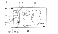
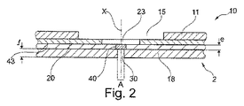
図1及び図2に示されたセキュア物品10、例えば文書、例えば紙幣、は、非不透明微小領域30の上に少なくとも部分的に重ねられた回折光学要素40を備えている、本発明に従うセキュリティ構造2を備えている。
The
物品10は、回折光学要素40への視覚的アクセスを与える窓15を有する基体11、特に紙製の基体11、を備えている。
The
検討されている例において、非不透明微小領域30は、基体11とともに結合された文書10の基体18、特に紙製の基体18、を貫いて形成された、軸Xを有する微小穿孔によって形成されている。
In the example being considered, the
該回折光学要素は、透明可塑性材料のフィルム43上に形成されており、フィルム43は、回折光学要素40の上及び微小穿孔30の上に少なくとも部分的に重ねられた非不透明領域23を有するセキュリティ要素20とともに結合されている。
The diffractive optical element is formed on a
熱可塑性フィルム43は、ポリエチレンテレフタレート(PET)製でありうる。
The
回折光学要素40は、距離を置いて位置する像形成平面に干渉パターンを生成する。
The diffractive
これらの様々な開口及び透明領域の少なくとも部分的な整列は、セキュア文書1の一方の面からもう一方の面まで延びる非不透明領域Aを画定する。
These at least partial alignments of the various openings and transparent regions define a non-opaque region A that extends from one side of the
図29及び図30を参照して、セキュリティ構造2を見る本発明に従う方法の例が説明される。
With reference to FIGS. 29 and 30, an example of a method according to the invention for viewing the
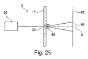
セキュリティ構造2の干渉パターンを見ることは、光源60を用いて非不透明微小領域30を照明することにより、回折光学要素40から距離を置いて位置する平面62において達成される。
Viewing the interference pattern of the
セキュリティ構造2は、好ましくは、セキュリティ構造2の平面が、光源60から生じた入射光に対して垂直に向けられ、非不透明微小領域30が好ましくは光源60の側に配置されるような態様で配置される。
The
非不透明微小領域30は特に、回折光学要素40が入射ビームのターゲットとされることを可能にする。
The
光源60は、好ましくは平行光源である。
The
図29に示されているように、光源60は、単色光源、特にレーザー、でありうる。その場合、像形成平面62は実在の平面であり、光源60から見てセキュリティ構造2の下流に配置される。干渉パターン66を見ることは、可搬式装置、特に、写真モード又はビデオ・モードに設定され像形成平面62に配置された携帯電話、の助けを借りて達成されることができる。干渉パターン66は、非不透明微小領域30を通して見られる。
As shown in FIG. 29, the
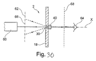
図30に示されているように、光源60は多色源でありうる。その場合、像形成平面62は仮想の平面であり、光源60から見てセキュリティ構造2の上流に配置される。干渉パターン66は、非不透明微小領域30を通して光源60を観察することによって見られる。
As shown in FIG. 30, the
セキュリティ構造2の認証は、セキュリティ構造2の上流又は下流に配置されたフィルター68の使用を必要としうる。このフィルターは、目で見ることができる波長がフィルターにかけられることを可能にすることができる。
Authentication of
セキュリティ構造2は、回折光学要素40によって生成された干渉パターン66を、セキュリティ構造2上又は関連物品10上に存在する1つ又は複数の追加の情報片、例えば、ウォーターマーク、印刷された特徴、金属化若しくは脱金属化、又は微小穿孔によって画定された比較パターン、と比較することによって、認証されることができる。非不透明微小領域30、特に脱金属化又は微小穿孔である非不透明微小領域30は、少なくとも部分的に、この比較パターンを構成しうる。
The
本発明は、特定のセキュア物品だけに限定されず、セキュア物品は、有価文書以外、特に識別文書又はカード、でありうる。従って、図1及び図2の例の基体11及び18は非繊維質でありうる。
The present invention is not limited to a specific secure article, and the secure article may be an identification document or card other than a valuable document. Accordingly, the
回折光学要素40は、以前に記載された方法のうちの1つの方法に従い熱可塑性フィルム43上に形成されうる。回折光学要素40の厚さeは、好ましくは50μm以下、又は、望ましくは25μm以下である。
The diffractive
回折光学要素40は、図2に示されているように、非不透明微小領域30の断面積よりも大きな断面積を有しうる。
The diffractive
非不透明微小領域30は、好ましくは1000000μm2未満、又は、望ましくは200000μm2以下、又は、さらに望ましくは10μm2〜200000μm2の範囲、又は、さらに望ましくは5000μm2〜200000μm2の範囲、の断面積Sを有する。
Non
非不透明微小領域30は、微小穿孔の形態をとるときに、様々なやり方で構成されうる。
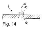
図14に示されているように、非不透明微小領域30は、可変断面積、特に、回折光学要素40の方向に次第に狭くなる可変断面積、を有しうる。
As shown in FIG. 14, the
図15は、その軸Xが、セキュリティ構造2の表面に対する垂線と非ゼロの角度αを形成する微小穿孔によって形成される非不透明微小領域30を示す。角度αは、−45°〜45°の範囲でありうる。
FIG. 15 shows a
図16に示されているように、セキュリティ構造2は、同じ表面S12上に開いた少なくとも2つの非不透明微小領域301及び302を備えていてもよく、その場合、それぞれの非不透明微小領域301及び302は、対応するそれぞれの回折光学要素401又は402の上に重ねられうる。見る角度を変化させることによって、この構成は、それを観察することが望まれている回折光学要素が選択されることを可能にする。望まれる場合には、これらの2つの干渉パターンを交互に見ることによって、アニメーションが観察されることができる。
As shown in FIG. 16, the
非不透明微小領域30は、不透明層を貫通する微小穿孔のそれとは異なる態様で形成されうる。
図17に示されているように、非不透明微小領域30は、無色又は非無色の透明非不透明材料で満たされうる。
As shown in FIG. 17, the
図18に示されているように、非不透明微小領域30は、印刷された特徴35によって境界が画定されうる。印刷された特徴がその上に形成された層38は、印刷された特徴とは反対側の面に回折光学要素40を担持する透明フィルムでありうる。
As shown in FIG. 18,
変形例として、非不透明微小領域30は、図19に示されているように、金属層37の脱金属化によって形成されうる。
As a modification, the
セキュリティ構造2は、回折光学要素に到達する光又は回折光学要素を出た光の経路中に置かれた光学フィルターを備えうる。
The
図20は、非不透明微小領域30の上に重ねられた吸収又は干渉光学フィルター80、特に着色フィルター80、を備えているセキュリティ構造2を示す。
FIG. 20 shows a
フィルター80は、回折光学要素40の上流又は下流に配置されうる。フィルター80は、干渉パターンが見られるときに、1つ又は複数の光波長が選択されることを可能にする。このフィルターは、表示色の選択を可能にすることによって、干渉パターンがパーソナライズされる(personalized)ことを可能にする。
The
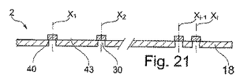
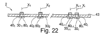
図21に示されているように、セキュリティ構造2は、複数の回折光学要素401、...、40iと、対応するそれぞれの軸X1、...、Xiを有する複数の対応するそれぞれの非不透明微小領域301、...、30iと、を備えうる。非不透明微小領域301、...、30iは、対応する回折光学要素401、...、40iの上にそれぞれ重ね合わせられる。
As shown in FIG. 21, the
セキュリティ構造2は、それぞれが少なくとも1つの回折光学要素401、...、40iと少なくとも部分的に重ね合わされた1つ又は複数の非不透明領域23を備えているセキュリティ要素20を備えうる。非不透明領域23は、少なくとも2つの回折光学要素401、...、40iと重ね合わされうる。
The
図23に示された変形例において、セキュリティ構造2は、複数の着色フィルター601、...、60i、特に、異なる色の着色フィルター601、...、60i、を備えている。複数の着色フィルター601、...、60iのそれぞれは、少なくとも1つの対応するそれぞれの回折光学要素401、...、40iの上にそれぞれ重ね合わせられる。
In the modification shown in FIG. 23, the
回折光学要素40の上及び非不透明微小領域30の上に少なくとも部分的に重ねられたセキュリティ要素20を、セキュリティ構造2が備えうることは、特に図2において見られることができる。より具体的には、示されているように、このセキュリティ要素20は、窓15を通して見られることができ、基体11と回折光学要素40を担持するフィルム43との間に置かれることができる。
It can be seen in particular in FIG. 2 that the
セキュリティ要素20は、好ましくは、少なくとも部分的に不透明であり、例えば少なくとも部分的に金属化されている。
The
非不透明領域23は、脱金属化又は穿孔によって形成されうる。
The
図1に示されているように、要素20は、窓15を通して見ることができるセキュリティ特徴、例えば、非不透明領域23の外側に置かれたパターン50の形態のセキュリティ特徴、を提供することができ、このパターン50は例えば、印刷又は脱金属化によって形成される。
As shown in FIG. 1, the
図1に示されているように、パターン50は例えば英数字から構成される。これは、銀行名、国名及び/又は紙幣の価値に関する情報を提供するテキストでありうる。
As shown in FIG. 1, the
パターン50は、国際公開第2006/066927号の教示に従い、透過光中の像を再現するラスター点の形態で形成されてもよく、その場合、パターン50の複数の脱金属化又は穿孔のうちの1つの脱金属化又は穿孔が非不透明微小領域30を形成することができる。
The
パターン50は、好ましくは、回折光学要素40によって生成された干渉パターン66の範囲内で部分的に、又は完全に見つけられる。例えば、図1において、紙幣の価値を表すパターン50は、やはり紙幣の価値を表す干渉パターンの範囲内で見つけられ、その場合、タイポグラフィは、同一でも又は異なっていてもよい。
The
一般的に言って、金属化された層を備えているセキュリティ要素20の場合、使用可能な金属として、アルミニウム、銅、金、鉄、銀、クロム、ニッケル、亜鉛、カドミウム、ビスマス、並びにこれらの合金及び酸化物の名が挙げられうる。
Generally speaking, in the case of a
セキュリティ要素20は、セキュリティパッチ、スレッド又はフォイルの形態をとりうる。
セキュリティ要素20がセキュリティスレッドである場合、セキュリティ要素20の幅は比較的に小さくてもよく、好ましくは10mm以下でありうる。
When the
窓15は、切抜きによって形成されてもよく、任意の形状の輪郭、例えば円形、楕円形又は図1に示されているような多角形、特に正多角形又は非正多角形の輪郭、を有しうる。
The
文書上に単一の窓15があってもよく、又は、文書は、幾つかの窓15を備えうる。この場合、窓15は、文書の同じ面又は反対側の面に配置されうる。
There may be a
窓15は、例えば、形成用の紙匹上での繊維の集積を変更することによって形成されてもよく、非不透明微小領域30は特に、微小針又は水ジェットによって、好ましくはレーザーアブレーションによって形成されうる。層11、18は例えば、湿っている段階において結合された繊維質層である。
The
2つの層11、18はそれぞれ、例えば10〜1000μm、又は、望ましくは50〜700μm、の範囲の厚さlを有する。
Each of the two
2つの層11、18は、天然繊維及び/又は合成繊維を含みうる。
The two
基体11及び18は、代替的に、非繊維質でありうる。
The
より一般的には、文書10が、少なくとも1つの繊維質層と熱可塑性材料の層とを含む多層構造を有しうる。
More generally, the
好ましくは、セキュア文書1に組み込まれる前に、回折光学要素40がセキュリティ要素20と積層される。
Preferably, the diffractive
変形例として、回折光学要素40は、熱又は冷での接着結合によってセキュリティ要素20に固定される。使用される接着剤は例えばポリマー接着剤型の透明接着剤、例えばNOLAXである。
As a variant, the diffractive
図2に示されているように、セキュリティ要素20と回折光学要素40とから構成されたアセンブリは、2つの層11、18間に組み込まれてもよく、セキュリティ要素20は、窓15の側に配置されうる。
As shown in FIG. 2, the assembly composed of the
一般的に言って、物品10は、様々な第1、第2又は第3レベルの付加されたセキュリティ要素を備えうる。追加的なセキュリティ要素のうち、幾つかは、特定の装置を用いることなく、日光又は人工の光の下で、目によって見ることが可能である。これらのセキュリティ要素は、例えば、繊維又は着色プランセット(planchette)、印刷されるか、又は全体若しくは一部が金属化されたスレッド、を含む。これらのセキュリティ要素は、第1レベルの要素であると言われる。
Generally speaking, the
他の種類の追加のセキュリティ要素は、比較的簡素な装置、例えば紫外(UV)又は赤外(IR)範囲で発光するランプ、の助けを借りることによってのみ見ることができる。これらのセキュリティ要素は、例えば、繊維、プランセット、ストリップ(strip)、スレッド又は粒子を含む。これらのセキュリティ要素は、肉眼によって可視であってもなくてもよく、例えば、365nmの波長を発するウッドランプ(Wood lamp)からの照明下で発光しうる。これらのセキュリティ要素は、第2レベルの要素であると言われる。 Other types of additional security elements can only be seen with the help of relatively simple devices, such as lamps that emit in the ultraviolet (UV) or infrared (IR) range. These security elements include, for example, fibers, plan sets, strips, threads or particles. These security elements may or may not be visible to the naked eye and can, for example, emit light under illumination from a wood lamp that emits a wavelength of 365 nm. These security elements are said to be second level elements.
他の追加の種類のセキュリティ要素は、それらの検出のために、より洗練された検出装置を必要とする。これらのセキュリティ要素は、例えば、1つ又は複数の外部励起源に対して同時に又は同時でなしに付された際に、特定の信号を生成することが可能である。信号の自動検出は、望まれる場合に、その文書が本物であると証明されることを可能とする。これらのセキュリティ要素は、例えば、アクティブ材料、粒子又は繊維の形態をとるトレーサーを備えており、これらのトレーサーが、オプトロニック、電気的、磁気的又は電磁的な励起に付される際に、特定の信号を生成することが可能である。これらのセキュリティ要素は、第3レベルの要素であると言われる。 Other additional types of security elements require more sophisticated detection devices for their detection. These security elements can generate specific signals when applied, for example, to one or more external excitation sources simultaneously or without. Automatic detection of the signal allows the document to be proven authentic if desired. These security elements comprise, for example, tracers in the form of active materials, particles or fibers, which are identified when subjected to optronic, electrical, magnetic or electromagnetic excitation. Can be generated. These security elements are said to be third level elements.
これらのセキュリティ要素のうちの少なくとも1つのセキュリティ要素は、回折光学要素40によって生成された干渉パターンの範囲内で見つけられる情報を定義しうる。
At least one of these security elements may define information found within the interference pattern generated by the diffractive
特に図2の例の場合がそうであるように、回折光学要素40と非不透明微小領域30を画定する層18とは互いに接触しうる。
As is the case in the example of FIG. 2 in particular, the diffractive
変形例として、回折光学要素40と非不透明微小領域30を画定する層18とは、1つ又は複数の中間層によって分離されうる。
As a variant, the diffractive
例えば、図3に示されているように、回折光学要素40を担持するフィルム43は、窓15を備えている基体11に隣接するような態様で配置されてもよく、セキュリティ要素20は、フィルム43と非不透明微小領域30との間に置かれうる。
For example, as shown in FIG. 3, the
好ましくは、図23に示されているように、回折光学要素40、特にフィルム43の回折光学要素40を担持する側の回折光学要素40、と層18とが、保護接着剤構造45、好ましくは接着剤材料とHRI材料との混合物の層を含む保護接着剤構造45、によって分離される。保護接着剤構造45は、回折光学要素40を担持するフィルム43と層18とが一緒にしっかりと取り付けられることを可能にする。HRI材料の存在は、接着剤材料と回折光学要素40との重ね合わせによって引き起こされることができる、回折光学要素の光学的効果の減衰又は取り消しを回避する。
Preferably, as shown in FIG. 23, the diffractive
回折光学要素40は、変形例として、接着剤材料の層をそれ自体が担持するHRI材料の層47、特に、真空蒸着によって回折光学要素40上に堆積させたHRI材料の層47、を担持しうる。この場合、層47は、この接着剤構造の存在に起因する、回折光学要素40の光学的効果の減衰又は取り消しから、回折光学要素40が保護されることを可能にする。接着剤構造の機械的保護は、接着剤材料の層46によって得られる。
The diffractive
変形例として、図24に示されているように、回折光学要素40、特にフィルム43の回折光学要素を担持する側、と層18とは、接着剤材料を含む接着剤構造46とHRI材料を含む保護構造47とによって分離され、保護構造47は、回折光学要素40、特に、フィルム43の回折光学要素40を担持する側、に施与され、接着剤構造46は、保護構造47と層18との間に配置される。
As an alternative, as shown in FIG. 24, the diffractive
保護構造47は、結合剤、好ましくはセキュアにされた結合剤、を含みうる。
The
図25に示された変形例において、フィルム43と層18とは、接着剤構造46によって分離されており、層18は、フィルム43の回折光学要素40のない側に位置する。回折光学要素40上に、HRI材料を含む保護構造47があってもよく、特に、保護構造47は、回折光学要素40を完全に覆いうる。この保護構造47は特に、セキュリティ構造2と物品10との結合の間、回折光学要素40が機械的に保護され、同時に光学的特性を維持することを可能にする。
In the variant shown in FIG. 25, the
図26に示された変形例において、フィルム43と層18とは、HRI材料の層47aと、結合剤の層47bと、接着剤材料を含む接着剤構造46とを含む保護構造47によって分離されている。HRI材料の層47aは、好ましくは、回折光学要素40を少なくとも部分的に覆い、結合剤の層47bは、好ましくは、HRI材料の層47aを覆う。
In the variation shown in FIG. 26, the
好ましくは、結合剤が、特にUV光、可視光及び/又はIR光による励起の下で発光性又は吸収性である1種又は複数種の物質によって、セキュアにされる。好ましくは、それらの発光性又は吸収性の物質が非散乱性であり、結合剤の層47bが透明である。それらの発光性又は吸収性の物質は、好ましくは、ナノメートルサイズの粒子である。 Preferably, the binder is secured by one or more substances that are luminescent or absorbing, especially under excitation by UV light, visible light and / or IR light. Preferably, the luminescent or absorbing material is non-scattering and the binder layer 47b is transparent. These luminescent or absorbing materials are preferably nanometer sized particles.
好ましくは、回折光学要素によって生み出される光学的効果を妨げないように、層47a、47b及び46が透明である。 Preferably, layers 47a, 47b and 46 are transparent so as not to interfere with the optical effects produced by the diffractive optical element.
保護構造47の堆積は、仏国特許出願公開第2961319号明細書の中で説明されているように、回折光学要素40上への印刷によって実施されてもよく、言い換えると、回折光学要素40の空洞がHRI材料で満たされる。
The deposition of the
保護構造47又は保護接着剤構造45は、金属酸化物、例えばTiO2、のナノ粒子、特に、1〜100nm、若しくは望ましくは5〜25nm、の範囲の直径を有するナノ粒子、及び/又は透明ワニス、及び/又は網状化可能な(reticulatable)有機結合剤、及び/又は顔料分散剤を含みうる。
保護接着剤構造45の厚さは、好ましくは1〜10ミクロン、又は望ましくは2〜5ミクロンの範囲である。
The thickness of the
好ましくは、接着剤構造46又は保護接着剤構造45が、回折光学要素40及び/又は回折光学要素40を担持するフィルム43と層18との間に、微小穿孔を介して導入される。好ましくは、独国特許出願公開第102011004935号明細書の中で説明されているように、微小穿孔を、外部環境、特に塵埃、から保護するために、層46又は45が、図23及び図24に示されているように、微小穿孔を満たすように導入される。
Preferably, an
図4に示されているように、セキュリティ要素20は、窓15の中に配置されてもよく、フィルム43はやはり、2つの層11と18の間に広がりうる。
As shown in FIG. 4, the
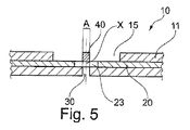
回折光学要素40は、回折光学要素40の周囲に連続して広がるフィルム43の範囲内に形成されうる。変形例として、回折光学要素40を形成するために使用されたフィルム43は、図5に示されているように、回折光学要素40を超えて広がらない。
The diffractive
図6に示されているように、フィルム43は、窓15の中に配置されうる。存在する場合、セキュリティ要素20に対しても同じことが当てはまりうる。
As shown in FIG. 6, the
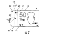
図7及び図8に示されているように、セキュリティ構造2は、回折光学要素40と、回折光学要素40の上に少なくとも部分的に重ねられた非不透明微小領域30を有するセキュリティ要素20とを備えうる。
As shown in FIGS. 7 and 8, the
第1の層11は窓15を有してもよく、第2の層18は非不透明領域32を有しうる。窓15と非不透明領域32とは、同じ形状及び同じサイズを有していても又は有していなくてもよく、セキュア文書1上及びセキュア文書1内に透明領域Aを形成するような態様で、窓15及び非不透明領域32は、回折光学要素40及び非不透明微小領域30と、少なくとも部分的に重ね合わされうる。セキュリティ構造2は、窓15と実質的に同じ形状を有してもよく、窓15の中に配置されうる。
The
図9に示されているセキュア文書1は、第1及び第2の層11、18によって形成された2つの基体11、18を備え、第1及び第2の層11、18はそれぞれ、微小穿孔30、16、好ましくはレーザーアブレーションによって形成された微小穿孔30、16、を有し、それらの微小穿孔の間に回折光学要素40を受け取る。回折光学要素40及び2つの微小穿孔30、16は重ね合わされている。
The
図11に示されているセキュア文書1は、窓15を有する第1の層を形成する第1の基体11と、非不透明微小領域30を有する第2の層を形成する第2の基体18とを備えている。セキュア文書1の一方の側からもう一方の側へ延び、回折光学要素40がその中に配置された透明領域Aをセキュア文書内に形成するように、窓15と微小穿孔30とは重ね合わされている。
The
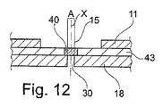
図12に示されているように、特に、回折光学要素40が熱可塑性フィルム43によって担持されるときには、回折光学要素40が2つの層11、18間に配置されてもよく、フィルム43は、2つの層11、18とじかに接触しうる。
As shown in FIG. 12, particularly when the diffractive
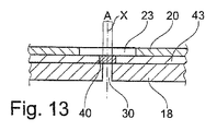
図13に示されているように、光学セキュリティ要素40は、基体18とセキュリティ要素20との間に配置されてもよく、この基体は、非不透明微小領域30を備えうる。
As shown in FIG. 13, the
図27に示されているように、セキュリティ要素20は、複数の微小穿孔19によって形成されたパターン50、ここでは文字AWを備えていてもよく、その場合、これらの微小穿孔のうちの1つが、非不透明微小領域30、例えばAの点、を形成することができる。パターンAWは、回折光学要素40によって生成された干渉パターン上に再現されることができる。
As shown in FIG. 27, the
非不透明微小領域40は、様々な形状、特に図1に示されているような円形の形状、又は他の任意の形状、例えば図28Aに示されているような三角形若しくは図28Bに示されているような三日月形の形状、でありうる。
The
本発明は、示された実施例に限定されない。 The invention is not limited to the embodiments shown.
示された実施例の特徴は、示されない変形例内に組み合わされうる。 The features of the embodiments shown can be combined in variants not shown.
表現「1つを備えている」は、反対のことが指定されている場合を除き、「少なくとも1つを備えている」と同義である。 The expression “having one” is synonymous with “having at least one” unless the opposite is specified.
Claims (34)
前記非不透明微小領域(30)の上に少なくとも部分的に重ねられたディジタル型の少なくとも1つの回折光学要素(40)であって、前記回折光学要素(40)から距離を置いて位置する像形成平面(62)に少なくとも1つの干渉パターン(66)を生成する前記少なくとも1つの回折光学要素(40)と
を備えているセキュリティ構造(2)。 At least one non-opaque microregion (30) having a cross-sectional area of 1000000 μm 2 or less;
At least one diffractive optical element (40) of digital type at least partially superimposed on the non-opaque microregion (30), the imaging being located at a distance from the diffractive optical element (40) Said at least one diffractive optical element (40) generating at least one interference pattern (66) in a plane (62).
前記回折光学要素を光源(60)を用いて照明する工程、
前記回折光学要素(40)から距離を置いて位置する像形成平面(62)における干渉パターン(66)の存在を、特に前記非不透明微小領域を通して、検証する工程
を含む、前記方法。 The security structure authentication method according to any one of claims 1 to 26, wherein:
Illuminating the diffractive optical element with a light source (60);
Verifying the presence of an interference pattern (66) in an imaging plane (62) located at a distance from the diffractive optical element (40), in particular through the non-opaque microregions.
The interference pattern (66) generated by the diffractive optical element (40) and the pattern (50) present on the document, in particular watermarks, printed features, metallization or demetallization, or microperforations. 34. A method according to claim 32 or 33, comprising comparing to a pattern (50) defined by.
Applications Claiming Priority (3)
| Application Number | Priority Date | Filing Date | Title |
|---|---|---|---|
| FR1355344 | 2013-06-10 | ||
| FR1355344A FR3006795B1 (en) | 2013-06-10 | 2013-06-10 | SAFETY STRUCTURE WITH DIFFRACTIVE OPTICAL ELEMENT |
| PCT/IB2014/062097 WO2014199296A1 (en) | 2013-06-10 | 2014-06-10 | Security structure having a diffractive optical element |
Publications (2)
| Publication Number | Publication Date |
|---|---|
| JP2016530118A true JP2016530118A (en) | 2016-09-29 |
| JP2016530118A5 JP2016530118A5 (en) | 2016-11-17 |
Family
ID=49322498
Family Applications (1)
| Application Number | Title | Priority Date | Filing Date |
|---|---|---|---|
| JP2016518621A Pending JP2016530118A (en) | 2013-06-10 | 2014-06-10 | Security structure with diffractive optical elements |
Country Status (5)
| Country | Link |
|---|---|
| EP (1) | EP3007903B1 (en) |
| JP (1) | JP2016530118A (en) |
| AU (1) | AU2014279723B2 (en) |
| FR (1) | FR3006795B1 (en) |
| WO (1) | WO2014199296A1 (en) |
Cited By (1)
| Publication number | Priority date | Publication date | Assignee | Title |
|---|---|---|---|---|
| JP2018529118A (en) * | 2015-08-07 | 2018-10-04 | ギーゼッケプルスデフリエント カーレンシー テクノロジー ゲーエムベーハーGiesecke+Devrient Currency Technology Gmbh | Security elements |
Families Citing this family (5)
| Publication number | Priority date | Publication date | Assignee | Title |
|---|---|---|---|---|
| GB2542783B (en) | 2015-09-29 | 2018-02-07 | De La Rue Int Ltd | Security print media and method of manufacture thereof |
| TWI699293B (en) * | 2015-10-02 | 2020-07-21 | 日商凸版印刷股份有限公司 | Forgery prevention structure |
| US10479128B2 (en) * | 2017-10-27 | 2019-11-19 | Assa Abloy Ab | Security feature |
| FR3080324B1 (en) * | 2018-04-23 | 2022-04-01 | Oberthur Fiduciaire Sas | SECURE SHEET |
| FR3085974B1 (en) * | 2018-09-14 | 2020-12-18 | Oberthur Fiduciaire Sas | METHOD OF MANUFACTURING A MATERIAL IN SHEET, MACHINE, SHEET MATERIAL AND CORRESPONDING SECURITY DOCUMENT |
Family Cites Families (13)
| Publication number | Priority date | Publication date | Assignee | Title |
|---|---|---|---|---|
| DE2451732A1 (en) * | 1974-10-31 | 1976-05-06 | Unitec Gmbh & Co Kg | IDENTITY CARRIER AND READING DEVICE FOR IT |
| WO1999037488A1 (en) | 1998-01-21 | 1999-07-29 | Securency Pty. Ltd. | Method of verifying the authenticity of a security document and document for use in such a method |
| AUPQ125999A0 (en) | 1999-06-28 | 1999-07-22 | Securency Pty Ltd | Method of producing a diffractive structure in security documents |
| ATE495908T2 (en) * | 2004-08-27 | 2011-02-15 | Kxo Ag | SECURITY DOCUMENT WITH PARTIAL MOTIF-FORMING VOLUME HOLOGRAM |
| SI1674286T1 (en) | 2004-12-23 | 2011-06-30 | Arjowiggins Security | Security element having a digitised mark and security support or document comprising same |
| CA2637399A1 (en) | 2006-01-16 | 2007-07-19 | Securency International Pty Ltd | Data storage in a diffractive optical element |
| CA2881437C (en) * | 2006-09-15 | 2018-11-27 | Innovia Security Pty Ltd | Radiation curable embossed ink security devices for security documents |
| GB2456449B (en) * | 2006-10-12 | 2010-06-02 | Australia Reserve Bank | A security document with micro-prisms |
| MTP4301B (en) | 2010-03-25 | 2011-10-26 | Securency Int Pty Ltd | High refractive index coatings and their use in the protection of surface relief structures |
| DE102010015302A1 (en) * | 2010-04-14 | 2011-10-20 | Bundesdruckerei Gmbh | Self-activating optical security element |
| DE102011004935A1 (en) | 2011-03-01 | 2012-09-06 | Bundesdruckerei Gmbh | Composite body and method of making a composite having an internal security feature |
| AU2011101567B4 (en) | 2011-11-30 | 2012-08-09 | Innovia Security Pty Ltd | Diffractive device |
| AU2013100172B4 (en) | 2013-02-19 | 2013-08-22 | Ccl Secure Pty Ltd | Security device with covert images |
-
2013
- 2013-06-10 FR FR1355344A patent/FR3006795B1/en not_active Expired - Fee Related
-
2014
- 2014-06-10 EP EP14733373.6A patent/EP3007903B1/en active Active
- 2014-06-10 WO PCT/IB2014/062097 patent/WO2014199296A1/en active Application Filing
- 2014-06-10 JP JP2016518621A patent/JP2016530118A/en active Pending
- 2014-06-10 AU AU2014279723A patent/AU2014279723B2/en active Active
Cited By (1)
| Publication number | Priority date | Publication date | Assignee | Title |
|---|---|---|---|---|
| JP2018529118A (en) * | 2015-08-07 | 2018-10-04 | ギーゼッケプルスデフリエント カーレンシー テクノロジー ゲーエムベーハーGiesecke+Devrient Currency Technology Gmbh | Security elements |
Also Published As
| Publication number | Publication date |
|---|---|
| FR3006795A1 (en) | 2014-12-12 |
| AU2014279723A1 (en) | 2015-12-24 |
| EP3007903A1 (en) | 2016-04-20 |
| EP3007903B1 (en) | 2020-05-20 |
| FR3006795B1 (en) | 2016-12-09 |
| AU2014279723B2 (en) | 2018-04-26 |
| WO2014199296A1 (en) | 2014-12-18 |
Similar Documents
| Publication | Publication Date | Title |
|---|---|---|
| JP4613178B2 (en) | Valuables that make up the moire pattern | |
| US9701151B2 (en) | Security thread | |
| JP4695327B2 (en) | Security paper and valuable documents created from it | |
| US20100253062A1 (en) | Banknote with edge windows | |
| US20140151996A1 (en) | Element for security document comprising an optical structure | |
| AU2014279723B2 (en) | Security structure having a diffractive optical element | |
| US20160075164A1 (en) | Security element comprising a volume hologram | |
| US8439402B2 (en) | Optical structure, in particular for a security document and/or a document of value | |
| US20150129780A1 (en) | Multilayer structure | |
| US20130003150A1 (en) | Security element including an optical structure | |
| FR3007318A1 (en) | MULTILAYER SAFETY STRUCTURE AND METHOD OF MANUFACTURING THE SAME | |
| RU2493969C2 (en) | Gonioluminiscent protective element and method of its production | |
| JP4728335B2 (en) | Anti-counterfeiting security object | |
| US20180117950A1 (en) | A security document or token | |
| KR100638978B1 (en) | Hologram thin film for anti-counterfeit using digital hidden image and preparing method thereof | |
| CN102774047B (en) | Anti-fake film structure of optical window | |
| AU2015100387B4 (en) | A Security Document or Token | |
| JP5621308B2 (en) | Anti-counterfeit media | |
| RU2374080C1 (en) | Protective element on basis of multilayer transparent colour-contrast damaged polymer structure for protected printing item, method of its production, material and printing item with counterfeit protection | |
| JP2014174294A (en) | Optical element | |
| RU2344047C1 (en) | Multilayer protective element (versions), counterfeit protected material and printing product | |
| JP2021005104A (en) | Optical element, printed matter and forgery prevention medium |
Legal Events
| Date | Code | Title | Description |
|---|---|---|---|
| A521 | Written amendment |
Free format text: JAPANESE INTERMEDIATE CODE: A523 Effective date: 20160927 |