JP2016524709A - Sensor system with active illumination - Google Patents
Sensor system with active illumination Download PDFInfo
- Publication number
- JP2016524709A JP2016524709A JP2016517191A JP2016517191A JP2016524709A JP 2016524709 A JP2016524709 A JP 2016524709A JP 2016517191 A JP2016517191 A JP 2016517191A JP 2016517191 A JP2016517191 A JP 2016517191A JP 2016524709 A JP2016524709 A JP 2016524709A
- Authority
- JP
- Japan
- Prior art keywords
- imaging system
- time
- illumination light
- imaging
- flight
- Prior art date
- Legal status (The legal status is an assumption and is not a legal conclusion. Google has not performed a legal analysis and makes no representation as to the accuracy of the status listed.)
- Pending
Links
Images


Classifications
-
- G—PHYSICS
- G01—MEASURING; TESTING
- G01S—RADIO DIRECTION-FINDING; RADIO NAVIGATION; DETERMINING DISTANCE OR VELOCITY BY USE OF RADIO WAVES; LOCATING OR PRESENCE-DETECTING BY USE OF THE REFLECTION OR RERADIATION OF RADIO WAVES; ANALOGOUS ARRANGEMENTS USING OTHER WAVES
- G01S7/00—Details of systems according to groups G01S13/00, G01S15/00, G01S17/00
- G01S7/48—Details of systems according to groups G01S13/00, G01S15/00, G01S17/00 of systems according to group G01S17/00
- G01S7/483—Details of pulse systems
- G01S7/484—Transmitters
-
- G—PHYSICS
- G01—MEASURING; TESTING
- G01S—RADIO DIRECTION-FINDING; RADIO NAVIGATION; DETERMINING DISTANCE OR VELOCITY BY USE OF RADIO WAVES; LOCATING OR PRESENCE-DETECTING BY USE OF THE REFLECTION OR RERADIATION OF RADIO WAVES; ANALOGOUS ARRANGEMENTS USING OTHER WAVES
- G01S17/00—Systems using the reflection or reradiation of electromagnetic waves other than radio waves, e.g. lidar systems
- G01S17/88—Lidar systems specially adapted for specific applications
- G01S17/89—Lidar systems specially adapted for specific applications for mapping or imaging
- G01S17/894—3D imaging with simultaneous measurement of time-of-flight at a 2D array of receiver pixels, e.g. time-of-flight cameras or flash lidar
-
- G—PHYSICS
- G01—MEASURING; TESTING
- G01S—RADIO DIRECTION-FINDING; RADIO NAVIGATION; DETERMINING DISTANCE OR VELOCITY BY USE OF RADIO WAVES; LOCATING OR PRESENCE-DETECTING BY USE OF THE REFLECTION OR RERADIATION OF RADIO WAVES; ANALOGOUS ARRANGEMENTS USING OTHER WAVES
- G01S7/00—Details of systems according to groups G01S13/00, G01S15/00, G01S17/00
- G01S7/48—Details of systems according to groups G01S13/00, G01S15/00, G01S17/00 of systems according to group G01S17/00
- G01S7/491—Details of non-pulse systems
- G01S7/4911—Transmitters
-
- G—PHYSICS
- G01—MEASURING; TESTING
- G01S—RADIO DIRECTION-FINDING; RADIO NAVIGATION; DETERMINING DISTANCE OR VELOCITY BY USE OF RADIO WAVES; LOCATING OR PRESENCE-DETECTING BY USE OF THE REFLECTION OR RERADIATION OF RADIO WAVES; ANALOGOUS ARRANGEMENTS USING OTHER WAVES
- G01S7/00—Details of systems according to groups G01S13/00, G01S15/00, G01S17/00
- G01S7/48—Details of systems according to groups G01S13/00, G01S15/00, G01S17/00 of systems according to group G01S17/00
- G01S7/491—Details of non-pulse systems
- G01S7/4912—Receivers
- G01S7/4915—Time delay measurement, e.g. operational details for pixel components; Phase measurement
Landscapes
- Engineering & Computer Science (AREA)
- Physics & Mathematics (AREA)
- Computer Networks & Wireless Communication (AREA)
- General Physics & Mathematics (AREA)
- Radar, Positioning & Navigation (AREA)
- Remote Sensing (AREA)
- Electromagnetism (AREA)
- Optical Radar Systems And Details Thereof (AREA)
- Length Measuring Devices By Optical Means (AREA)
- Image Analysis (AREA)
- Image Input (AREA)
Abstract
本発明は、能動照明に基づいた視覚センサに関する。撮像システムは、撮像センサを含み、各々が近赤外域に波長を有する少なくとも2つの異なる照明光源によって照明されるシーンの画像を処理するように構成されている。一変形例では、撮像システムは、3次元飛行時間測定を行うために使用される変調周波数よりも低い変調周波数を有する照明光源を使用するように構成されている。一変形例では、撮像システムは、飛行時間の測定に使用されたフレーム単位サンプル数よりも少ないフレーム単位サンプル数を取得するように構成されている。The present invention relates to a visual sensor based on active illumination. The imaging system includes an imaging sensor and is configured to process an image of a scene illuminated by at least two different illumination sources each having a wavelength in the near infrared region. In one variation, the imaging system is configured to use an illumination light source having a modulation frequency that is lower than the modulation frequency used to perform the three-dimensional time-of-flight measurement. In one variation, the imaging system is configured to acquire a number of frame-unit samples that is less than the number of frame-unit samples used to measure time of flight.
Description
発明の分野
本発明は、能動照明に基づいた視覚センサに関する。本発明は、能動撮像システムの画像品質、動作範囲および背景光安定性を改善する。このようなセンサは、一般的には、周囲環境、物体または人間を検出および測定するために使用される。
The present invention relates to visual sensors based on active illumination. The present invention improves the image quality, operating range and background light stability of an active imaging system. Such sensors are typically used to detect and measure the surrounding environment, objects or people.
背景技術
能動照明は、多くのカメラの設計に実装され、カメラの測定結果を改善する。カメラは、ピクセル配列を有する撮像センサを含む電気光学装置として理解される。
Background Art Active lighting is implemented in many camera designs and improves camera measurement results. A camera is understood as an electro-optical device that includes an imaging sensor having a pixel array.
多くの機械視覚設備において、能動照明は、カメラシステムの特定の光強度レベルを保証するために使用される。これによって、能動システムの性能は、周囲環境の照明変化を受けにくくなり、安定性および信頼性が改善される。また、システムに照明パワーを追加することにより、より短い露光を設定することができ、より高いフレームレートを達成することができる。 In many machine vision facilities, active illumination is used to ensure a specific light intensity level of the camera system. This makes the performance of the active system less susceptible to ambient lighting changes and improves stability and reliability. Also, by adding illumination power to the system, shorter exposures can be set and higher frame rates can be achieved.
能動照明カメラシステムを備える他のセンサは、シーンに位置する対象物の特定性質を使用する。たとえば、設備は、シーンに配置され、容易に認識されかつ追跡され得る反射板を使用する場合がある。 Other sensors with active illumination camera systems use the specific nature of objects located in the scene. For example, the equipment may use reflectors that are placed in the scene and can be easily recognized and tracked.
他の設備は、対象物の特定の反射特性、たとえば眼の反射特性を使用している。能動照明を備えたシステムによって捕捉された眼の典型的な後方反射を使用して、眼を検出および追跡し、眼の瞬きをカウントすることによって、たとえば運転者の眠気を検出し、疲労測定センサを構築することができる。 Other equipment uses certain reflection characteristics of the object, such as the reflection characteristics of the eye. A typical back reflection of the eye captured by a system with active illumination is used to detect and track the eye and count eye blinks, for example to detect driver drowsiness and fatigue measurement sensors Can be built.
干渉計装置において、能動システムは、対象物および参照物を照明する。反射光の干渉に基づき、深度を測定および分析することができる。 In the interferometer apparatus, the active system illuminates objects and references. Based on the interference of reflected light, the depth can be measured and analyzed.
その他の能動システムは、照明を変調することによって、周囲環境に関する情報をより詳細に取得する。一般的には、このような照明は、時間上変調され(時間変調)または空間上変調されるため、たとえば周囲環境を3次元にマッピングするための距離測定に適用することができる。時間変調は、いわゆる飛行時間型(TOF、time-of-flight)カメラに(間接または直接に)実装されている。空間変調は、三角測量に基づく深度測定システムに使用され、構造化光技術とも呼ばれている。 Other active systems obtain more detailed information about the surrounding environment by modulating the lighting. In general, such illumination is time-modulated (time-modulated) or spatially-modulated, so that it can be applied, for example, to distance measurements for mapping the surrounding environment in three dimensions. Time modulation is implemented (indirectly or directly) in so-called time-of-flight (TOF) cameras. Spatial modulation is used in depth measurement systems based on triangulation and is also called structured light technology.
飛行時間型撮像センサのピクセルは、光生成電荷を記憶ノードに非常に高速に転送することを保証するための専用ピクセル設計である。より高い変調周波数は、より良い深度ノイズ性能をもたらす。したがって、TOF復調ピクセルは、一般的には、数十MHzから数百MHzまでの範囲に動作する。また、TOF撮像システムの動作範囲を増加するために、TOFピクセルは、しばしば背景光をピクセルレベルで抑制する。殆どの実装において、TOFピクセルは、2つのサンプル信号をピクセルごとに格納および積算するための2つの記憶ノードを含む。 The pixels of the time-of-flight imaging sensor are a dedicated pixel design to ensure that photogenerated charges are transferred very quickly to the storage node. A higher modulation frequency results in better depth noise performance. Thus, TOF demodulating pixels typically operate in the range of tens to hundreds of MHz. Also, TOF pixels often suppress background light at the pixel level to increase the operating range of the TOF imaging system. In most implementations, the TOF pixel includes two storage nodes for storing and accumulating two sample signals pixel by pixel.
発明の開示
太陽光などの背景光信号を除去することができれば、すべての能動照明撮像システムのロバスト性が改善される。殆どの場合、背景光信号のキャンセルは、照明をオンにしたときおよび照明をオフにした場合に各々2つの連続画像を取得することによって達成される。2つの画像に対して減算を行うことによって、能動照明のみの光強度情報を含む画像が得られる。このような手法の欠点は、まず、システムが2つの別々の画像を取得する必要があることである。シーンまたはシーン内の対象物は、画像ごとに変動する可能性があり、この場合に、背景の減算は、理想的ではない。また、取得した2つの画像に対し、背景光から能動光までのすべての動作信号範囲を処理する必要がある。背景光信号が必要とされなくても、システムの動作範囲を食い尽くす。
DISCLOSURE OF THE INVENTION The robustness of all active illumination imaging systems is improved if background light signals such as sunlight can be removed. In most cases, cancellation of the background light signal is achieved by acquiring two successive images each when the illumination is turned on and when the illumination is turned off. By performing subtraction on the two images, an image including light intensity information of only active illumination is obtained. The disadvantage of such an approach is that the system first needs to acquire two separate images. The scene or objects within the scene can vary from image to image, in which case background subtraction is not ideal. Further, it is necessary to process the entire operation signal range from background light to active light for the two acquired images. Even if a background light signal is not required, it will eat up the operating range of the system.
本発明の目的は、改善された動作範囲を有する撮像システムを提供することである。本発明のさらなる目的は、改善された解像度およびより少ない光電力消費で3次元計測を行うための撮像システムを提供することである。さらに、本発明の目的は、2次元強度および3次元撮像システムを提供することである。 It is an object of the present invention to provide an imaging system with an improved operating range. It is a further object of the present invention to provide an imaging system for performing three-dimensional measurements with improved resolution and less optical power consumption. Furthermore, an object of the present invention is to provide a two-dimensional intensity and three-dimensional imaging system.
本発明によれば、これらの目的は、特に独立請求項の特徴により達成される。また、さらなる有利な実施形態は、従属請求項および明細書に依存する。 According to the invention, these objects are achieved in particular by the features of the independent claims. Further advantageous embodiments also depend on the dependent claims and the description.
本発明によれば、撮像システムは、撮像センサを含む。撮像システムは、各々が近赤外域に波長を有する少なくとも2つの異なる照明光源によって照明されるシーンの画像を処理するように構成されている。好ましくは、波長は、800〜1000nmである。照明光源は、撮像センサに隣接して配置されてもよく、撮像センサと同調されてもよい。少なくとも2つの照明光源は、閉塞を最小化するように配置されてもよい。 According to the present invention, the imaging system includes an imaging sensor. The imaging system is configured to process an image of a scene illuminated by at least two different illumination sources each having a wavelength in the near infrared region. Preferably, the wavelength is 800 to 1000 nm. The illumination light source may be disposed adjacent to the imaging sensor and may be tuned with the imaging sensor. The at least two illumination light sources may be arranged to minimize occlusion.
いくつかの実施形態において、少なくとも2つの異なる照明光源の波長は、異なる。たとえば、少なくとも1つの照明光源の波長は、約850nmであり、少なくとも1つの照明光源の波長は、約940nmである。 In some embodiments, the wavelengths of at least two different illumination sources are different. For example, the wavelength of the at least one illumination light source is about 850 nm, and the wavelength of the at least one illumination light source is about 940 nm.
いくつかの実施形態において、少なくとも2つの異なる照明光源は、少なくとも1つの構造化照明光源を含む。たとえば、撮像センサが飛行時間型撮像センサである場合、飛行時間の測定および構造化照明光源の測定による利点を提供する。 In some embodiments, the at least two different illumination sources include at least one structured illumination source. For example, if the imaging sensor is a time-of-flight imaging sensor, it provides advantages by measuring time-of-flight and structured illumination sources.
いくつかの実施形態において、少なくとも2つの異なる照明光源は、少なくとも1つの均一照明光源を含む。 In some embodiments, the at least two different illumination sources include at least one uniform illumination source.
いくつかの実施形態において、少なくとも2つの異なる照明光源は、各々が近赤外域に波長を有するが、少なくとも1つの均一照明光源と少なくとも1つの構造化照明光源とを含む。構造化照明光源による画像の取得と均一照明光源による画像の取得とは、交互に行われてもよい。構造化照明光源に基づいて取得した実際の原始画像は、通常の色または強度表現で画像を取得した環境を表さないため、構造化照明光源に基づいた最新のシステムは、第2の撮像センサ装置、一般的にはRGBセンサを追加する。本発明により提案されたように、2つの異なる照明光源、たとえば1つの構造化照明光源および1つの均一照明光源を実装することによって、撮像システムは、同一の撮像センサを用いて、深度情報を導出し、代表強度の(または白黒の)画像を生成するができる。これにより、3Dマップを2D強度画像に容易にかつ一対一にマッピングすることができる。撮像センサがTOF撮像センサである場合、TOF撮像センサおよび2つの異なる照明光源をさらに時間的に変調および同期してもよい。 In some embodiments, the at least two different illumination sources each have a wavelength in the near infrared range, but include at least one uniform illumination source and at least one structured illumination source. Acquisition of an image with a structured illumination light source and acquisition of an image with a uniform illumination light source may be performed alternately. Since the actual original image acquired based on the structured illumination light source does not represent the environment in which the image was acquired with a normal color or intensity representation, the latest system based on the structured illumination light source is the second imaging sensor. Add device, generally RGB sensor. As proposed by the present invention, by implementing two different illumination sources, eg, one structured illumination source and one uniform illumination source, the imaging system uses the same imaging sensor to derive depth information. Then, a representative intensity (or black and white) image can be generated. As a result, the 3D map can be easily and one-to-one mapped to the 2D intensity image. If the imaging sensor is a TOF imaging sensor, the TOF imaging sensor and the two different illumination sources may be further modulated and synchronized in time.
いくつかの実施形態において、撮像システムは、構造化照明光源と均一照明光源とを含む。構造化照明光源と均一照明光源とは、同様の中心波長、好ましくは800〜1000nmの間の中心波長を有する。このような実施形態において、構造化照明光源からの画像および均一照明光源からの画像は、それぞれ同一の光路を介して撮像されることができ、この光路には狭帯域通過光学フィルタを実装することができる。狭帯域通過フィルタを実装することによって、できるだけ多くの背景光信号を光学的に遮断することができる。 In some embodiments, the imaging system includes a structured illumination source and a uniform illumination source. The structured illumination light source and the uniform illumination light source have similar center wavelengths, preferably between 800 and 1000 nm. In such an embodiment, the image from the structured illumination light source and the image from the uniform illumination light source can each be imaged through the same optical path, and a narrow band pass optical filter is implemented in this optical path. Can do. By implementing a narrow band pass filter, as many background light signals as possible can be optically blocked.
いくつかの実施形態において、撮像センサは、飛行時間型センサである。
いくつかの実施形態において、少なくとも2つの異なる照明光源は、露光中に時間的に変調される少なくとも1つの照明光源を含む。適切な時間変調方式は、画像取得中にシーンの変化または物体の移動によって生じた画像の乱れを低減することができ、範囲内の他の撮像システムからの干渉を回避することもできる。
In some embodiments, the imaging sensor is a time-of-flight sensor.
In some embodiments, the at least two different illumination sources include at least one illumination source that is temporally modulated during exposure. Appropriate time modulation schemes can reduce image perturbations caused by scene changes or object movement during image acquisition, and can also avoid interference from other imaging systems in range.
いくつかの実施形態において、少なくとも2つの異なる照明光源は、同一の発光ダイに設けられる。このことは、少なくとも2つの照明光源が構造化照明光源であり、両方とも時間的に変調される場合に、特に有用である。同一の発光ダイに設けられた少なくとも2つの構造化照明光源を備え、撮像センサと同期するように少なくとも2つの構造化照明光源を変調するように構築されたシステムは、より高い情報密度で構造化画像を取得することができる。 In some embodiments, at least two different illumination sources are provided on the same light emitting die. This is particularly useful when at least two illumination sources are structured illumination sources, both of which are modulated in time. A system built with at least two structured illumination sources on the same light emitting die and configured to modulate at least two structured illumination sources to synchronize with the imaging sensor is structured with higher information density Images can be acquired.
さらに、本発明は、撮像センサを用いた撮像方法に関する。各々が近赤外域に波長を有する少なくとも2つの異なる照明光源によって照明されるシーンの画像が処理される。一変形例において、少なくとも2つの異なる照明光源は、異なる波長を有する。一変形例において、少なくとも2つの異なる照明光源は、少なくとも1つの構造化照明光源を含む。一変形例において、少なくとも2つの異なる照明光源は、少なくとも1つの均一照明光源を含む。一変形例において、使用された撮像センサは、飛行時間型センサである。一変形例において、少なくとも2つの異なる照明光源は、飛行時間の測定に使用された変調周波数よりも低い変調周波数で時間的に変調される少なくとも1つの均一照明光源を含む。一変形例において、少なくとも2つの異なる照明光源は、露光中に時間的に変調される少なくとも1つの構造化照明光源を含む。一変形例において、少なくとも2つの異なる照明光源は、同一の発光ダイに設けられる。 Furthermore, the present invention relates to an imaging method using an imaging sensor. An image of the scene illuminated by at least two different illumination sources each having a wavelength in the near infrared region is processed. In one variation, the at least two different illumination sources have different wavelengths. In one variation, the at least two different illumination sources include at least one structured illumination source. In one variation, the at least two different illumination sources include at least one uniform illumination source. In one variant, the imaging sensor used is a time-of-flight sensor. In one variation, the at least two different illumination sources include at least one uniform illumination source that is temporally modulated with a modulation frequency that is lower than the modulation frequency used to measure time of flight. In one variation, the at least two different illumination sources include at least one structured illumination source that is temporally modulated during exposure. In a variant, at least two different illumination sources are provided on the same light emitting die.
本発明によれば、飛行時間型センサを含む撮像システムは、飛行時間の3次元測定に使用された変調周波数よりも低い変調周波数を有する照明光源を使用するように構成されている。 In accordance with the present invention, an imaging system that includes a time-of-flight sensor is configured to use an illumination light source that has a modulation frequency that is lower than the modulation frequency used for the three-dimensional measurement of time of flight.
特定の好ましい実施形態において、本発明は、典型的に各ピクセルに2つの記憶ノードを有する飛行時間型センサまたは飛行時間型構造、好ましくはある種のインピクセル背景抑制機能を有する飛行時間型センサまたは飛行時間型構造を撮像システムに実装することを提案する。また、能動的に照明される撮像システムにおいて、飛行時間型撮像センサおよび照明光源は、低い変調周波数に制御されるため、実際の飛行時間型信号は、サンプリング信号に殆ど影響を与えない。さらに、本発明は、飛行時間の実際測定の実行に十分ではないサンプル数および取得回数を獲得する取得タイミングを撮像システム上で実行し、これらの取得画像のみに基づき画像を評価することを提案する。最も実用的な実装において、飛行時間型ピクセルは、2つの記憶ノードを含み、少なくとも2つ、最も一般的に4つの連続かつ位相遅延の画像を捕捉することによって深度情報を導き出す。この実施形態において、好ましくは、ピクセルの一方の記憶ノードを用いて、背景光信号のみを積算した後、背景光信号と能動的に出射され、反射された光とを積算する他方の記憶ノードから積算された背景光信号を減算する。信号の取得、信号の積算および2つの飛行時間型ピクセル記憶ノードへの転送は、好ましくは、取得中に複数回に繰り返し且つ交互に行われる。得られたピクセル差分の出力は、能動的に出射された信号のみを表すことになり、システムを周囲環境の照明条件の変化に対してよりロバストにすることができる。 In certain preferred embodiments, the present invention typically includes a time-of-flight sensor or time-of-flight structure with two storage nodes in each pixel, preferably a time-of-flight sensor with some in-pixel background suppression function or It is proposed to implement a time-of-flight structure in an imaging system. In an imaging system that is actively illuminated, the time-of-flight imaging sensor and the illumination light source are controlled to have a low modulation frequency, so that the actual time-of-flight signal has little effect on the sampling signal. Furthermore, the present invention proposes to execute an acquisition timing on the imaging system to acquire the number of samples and the number of acquisitions that are not sufficient for performing the actual measurement of the flight time, and to evaluate the image based only on these acquired images. . In the most practical implementation, a time-of-flight pixel includes two storage nodes and derives depth information by capturing at least two, most commonly four consecutive and phase delayed images. In this embodiment, preferably, one storage node of the pixel is used to integrate only the background light signal, and then from the other storage node that integrates the background light signal and the actively emitted and reflected light. The accumulated background light signal is subtracted. Signal acquisition, signal integration, and transfer to two time-of-flight pixel storage nodes are preferably repeated and alternated multiple times during acquisition. The resulting pixel difference output represents only actively emitted signals, making the system more robust to changes in ambient lighting conditions.
いくつかの実施形態において、変調周波数は、100Hz〜1MHzの間にある。より遅い変調は、数十MHzでトグルする最先端の飛行時間測定システムに比べて、撮像システムの電力消費を低減する。また、より遅い変調は、照明光源および駆動系の速度要件を低減し、変調効率および復調効率を向上させる。一般的に飛行時間の測定に遅すぎる高出力LEDのような高効率高出力の光源を実現することができる。 In some embodiments, the modulation frequency is between 100 Hz and 1 MHz. Slower modulation reduces the power consumption of the imaging system compared to state-of-the-art time-of-flight measurement systems that toggle at tens of MHz. Slower modulation also reduces the speed requirements of the illumination light source and drive system and improves modulation efficiency and demodulation efficiency. In general, a high-efficiency high-power light source such as a high-power LED that is too slow for time-of-flight measurement can be realized.
いくつかの実施形態において、撮像システムは、飛行時間型センサのピクセルレベルに対して直接減算を行うように構成されている。飛行時間型ピクセルのオンピクセル背景光のキャンセルは、背景光による飽和を回避するように、能動照明光源を備える他のシステムを援助することができる。また、背景レベルが既にピクセルレベルで減算され、変換する必要がないため、アナログからデジタルに変換する要件が緩和される。さらに、能動照明を備えるシステム内に光を変調すること、同一フレームの取得時に信号光と背景光との積算を交互に行うことおよび数サイクルに亘って信号光と背景光とを積算することは、シーンの変動を軽減し、適切な時間変調方式とともに実行すれば、干渉を減少しながら、いくつかのシステム上で並列処理を行うことができる。 In some embodiments, the imaging system is configured to perform a direct subtraction on the pixel level of the time-of-flight sensor. On-pixel background light cancellation of time-of-flight pixels can assist other systems with active illumination sources to avoid saturation with background light. Also, since the background level is already subtracted at the pixel level and does not need to be converted, the requirement to convert from analog to digital is relaxed. Furthermore, modulating light within a system with active illumination, alternately integrating signal light and background light during acquisition of the same frame, and integrating signal light and background light over several cycles If executed with an appropriate time modulation scheme to reduce scene variations, parallel processing can be performed on several systems while reducing interference.
いくつかの実施形態において、撮像システムは、構造化照明光源を使用するように構成されている。構造化照明光源は、飛行時間型撮像センサと同期され、構造化照明光源に基づいて画像を取得し、深度情報を導き出すために使用される。 In some embodiments, the imaging system is configured to use a structured illumination light source. The structured illumination light source is synchronized with the time-of-flight imaging sensor and is used to acquire an image and derive depth information based on the structured illumination light source.
いくつかの実施形態において、撮像システムは、飛行時間型撮像センサと、少なくとも1つの照明光源とを含む。飛行時間型撮像センサは、後方反射光をサンプリングするために使用される。信号は、飛行時間原理に基づいて深度情報を導き出すのに十分ではない取得回数および取得されたフレームあたりのサンプルに基づいて評価される。 In some embodiments, the imaging system includes a time-of-flight imaging sensor and at least one illumination source. Time-of-flight imaging sensors are used to sample back reflected light. The signal is evaluated based on the number of acquisitions and samples per acquired frame that are not sufficient to derive depth information based on the time-of-flight principle.
いくつかの実施形態において、撮像システムは、擬似ランダムに変調される照明光源を使用することによって、異なる取得システムの間の異なる干渉を最小化にするように構成されている。 In some embodiments, the imaging system is configured to minimize different interference between different acquisition systems by using a pseudo-randomly modulated illumination source.
いくつかの実施形態において、撮像システムは、少なくとも2つの異なる波長を有する少なくとも2つの照明光源を使用するように構成されている。差分読み出しまたはオンピクセル減算を行うことによって、2つの照明光源の差分画像を直接測定することができる。これにより、たとえば、非常に強固な眼追跡システムを構築することができる。 In some embodiments, the imaging system is configured to use at least two illumination sources having at least two different wavelengths. By performing differential readout or on-pixel subtraction, the differential image of the two illumination sources can be measured directly. Thereby, for example, a very strong eye tracking system can be constructed.
いくつかの実施形態において、本発明は、飛行時間型センサを用いた撮像システムを提供する。撮像システム内の照明光源は、3次元時間の飛行測定を実行するために使用された変調周波数よりも低い変調周波数を有する。 In some embodiments, the present invention provides an imaging system using a time-of-flight sensor. The illumination source in the imaging system has a modulation frequency that is lower than the modulation frequency used to perform the three-dimensional time flight measurement.
いくつかの実施形態において、撮像システムは、飛行時間の測定を行うために必要とされたフレーム単位サンプル数よりも少ないフレーム単位サンプル数を取得するように構成されている。 In some embodiments, the imaging system is configured to acquire a number of frame-unit samples that is less than the number of frame-unit samples required to perform the time-of-flight measurement.
いくつかの実施形態において、飛行時間型センサと少なくとも1つの照明光源とを含む撮像システムのタイミングは、飛行時間の測定を導き出すために必要とされたフレーム単位サンプル数よりも少ないフレーム単位サンプル数を取得するように構成されている。 In some embodiments, the timing of an imaging system that includes a time-of-flight sensor and at least one illumination source has a number of frame-unit samples that is less than the number of frame-unit samples required to derive a time-of-flight measurement. Is configured to get.
さらに、本発明は、飛行時間型センサを用いた撮像方法に関する。飛行時間の測定に使用された変調周波数よりも低い変調周波数を有する照明光源が使用される。一変形例において、使用された前記変調周波数は、100Hz〜1MHzの間にある。一変形例において、飛行時間型センサのピクセルレベルに対して、直接減算を行う。一変形例において、構造化照明光源を使用する。一変形例において、少なくとも2つの異なる波長を有する2つの照明光源を使用する。一変形例において、擬似ランダムに変調される照明光源を使用する。一変形例において、飛行時間の測定に必要とされたフレーム単位サンプル数よりも少ないフレーム単位サンプル数を取得する。 Furthermore, the present invention relates to an imaging method using a time-of-flight sensor. An illumination source is used that has a modulation frequency that is lower than the modulation frequency used to measure the time of flight. In a variant, the modulation frequency used is between 100 Hz and 1 MHz. In one variation, direct subtraction is performed on the pixel level of the time-of-flight sensor. In one variation, a structured illumination source is used. In one variation, two illumination sources having at least two different wavelengths are used. In one variation, a pseudo-randomly modulated illumination source is used. In one variation, a number of frame-unit samples is obtained that is less than the number of frame-unit samples required for time-of-flight measurement.
本発明によれば、撮像システムは、飛行時間の測定に必要とされたフレーム単位サンプル数よりも少ないフレーム単位サンプル数を取得するように構成されている。 According to the present invention, the imaging system is configured to acquire a number of frame-unit samples that is less than the number of frame-unit samples required for time-of-flight measurement.
いくつかの実施形態において、撮像システムは、飛行時間の測定に使用された変調周波数よりも低い変調周波数、特に100Hz〜1MHzの間の変調周波数を有する照明光源を使用するように構成されている。 In some embodiments, the imaging system is configured to use an illumination light source that has a modulation frequency that is lower than the modulation frequency used for time-of-flight measurements, particularly between 100 Hz and 1 MHz.
いくつかの実施形態において、撮像システムは、飛行時間型センサのピクセルレベルに対して、直接減算を行うように構成されている。 In some embodiments, the imaging system is configured to perform direct subtraction on the pixel level of the time-of-flight sensor.
いくつかの実施形態において、撮像システムは、構造化照明光源を使用するように構成されている。 In some embodiments, the imaging system is configured to use a structured illumination light source.
いくつかの実施形態において、撮像システムは、少なくとも2つの異なる波長を有する少なくとも2つの照明光源を使用するように構成されている。 In some embodiments, the imaging system is configured to use at least two illumination sources having at least two different wavelengths.
いくつかの実施形態において、撮像システムは、擬似ランダム時間に変調された照明光源を使用するように構成されている。 In some embodiments, the imaging system is configured to use an illumination light source modulated in pseudo-random time.
さらに、本発明は、飛行時間型センサを用いた撮像方法に関する。方法は、飛行時間の測定に必要とされたフレーム単位サンプル数よりも少ないフレーム単位サンプル数を取得する。一変形例において、使用された照明光源は、飛行時間の測定に使用された変調周波数よりも低い変調周波数、特に100Hz〜1MHzの間の変調周波数を有する。一変形例において、飛行時間型センサのピクセルレベルに対して、直接減算を行う。一変形例において、構造化照明光源を使用する。一変形例において、少なくとも2つの異なる波長を有する2つの照明光源を使用する。一変形例において、擬似ランダム時間に変調される照明光源を使用する。 Furthermore, the present invention relates to an imaging method using a time-of-flight sensor. The method obtains a number of frame-by-frame samples that is less than the number of frame-by-frame samples required to measure time of flight. In one variant, the illumination source used has a modulation frequency that is lower than the modulation frequency used for the measurement of time of flight, in particular between 100 Hz and 1 MHz. In one variation, direct subtraction is performed on the pixel level of the time-of-flight sensor. In one variation, a structured illumination source is used. In one variation, two illumination sources having at least two different wavelengths are used. In one variation, an illumination source that is modulated in pseudo-random time is used.
本明細書に記載の本発明は、本明細書の以下の詳細な説明および添付図面からより理解されるであろう。詳細な説明および添付図面は、添付の特許請求の範囲に記載の本発明を限定するものと考えるべきではない。 The invention described herein will be better understood from the following detailed description of the specification and the accompanying drawings. The detailed description and accompanying drawings should not be construed to limit the invention as set forth in the appended claims.
発明を実施するための形態
飛行時間型撮像システムは、出射光が測定システムから対象物まで走行して、対象物から測定システムに戻って来る時間を決定することができる。出射光信号は、一定の距離に位置する対象物によって反射される。この距離は、光が測定システムから対象物まで走行して、対象物から測定システムに戻って来る走行時間により起因した出射信号と受信信号との間の時間遅延に対応する。間接的な飛行時間測定において、この距離に依存する時間遅延は、出射信号と受信信号との間の位相遅延に対応する。また、受信信号は、後方に反射された出射信号だけでなく、たとえば太陽または他の光源からの背景光信号を含む場合がある。最新の飛行時間型ピクセルは、図1aに示されている。飛行時間型ピクセルは、第1のスイッチSW1を介して記憶ノードC1に接続され、第2のスイッチSW2を介して記憶ノードC2に接続された感光性領域Pを含む。光生成電子のサンプリングは、スイッチSW1を閉合してSW2を開放することにまたはその逆によって行われる。スイッチSW1およびSW2は、制御部によって照明光源と同期される。妥当な飛行時間測定を可能にするために、スイッチSW1、SW2および照明光源が約10MHzから200MHzを超える範囲に動作する必要があり、数ナノ秒の時間に光生成電荷を感光領域Pから記憶ノードC1またはC2のいずれかに転送しなければならない。飛行時間型ピクセルは、このような高速サンプリングに満たすように特別に設計されたのものである。このような高速飛行時間型ピクセル構造の可能な実装例は、米国特許US5856667、欧州特許出願EP1009984B1、欧州特許出願EP1513202B1または米国特許出願US7884310B2に記載されている。飛行時間型ピクセルの出力回路Cは、一般的に、読み出し増幅器とリセットノードとを含む。多くの飛行時間型ピクセルの実現例において、インピクセル出力回路Cは、記憶ノードC1およびC2内の2つのサンプルに対して共通レベル除去または背景減算を行う回路をさらに含む。このようなインピクセル共通信号レベルの除去は、飛行時間型ピクセルの動作範囲を大幅に増大する。サンプルを積算しながら、共通レベルの除去を行う可能な実現例は、PCT公開WO2009135952A2および米国特許出願US7574190B2に開示されている。データを読み出すサイクル中に露光した後にサンプルの共通信号レベルの減算を行う別の手法は、米国特許出願US7897928B2に記載されている。
DETAILED DESCRIPTION OF THE INVENTION A time-of-flight imaging system can determine the time when emitted light travels from a measurement system to an object and returns from the object to the measurement system. The emitted light signal is reflected by an object located at a certain distance. This distance corresponds to the time delay between the outgoing signal and the received signal due to the travel time when light travels from the measurement system to the object and returns from the object to the measurement system. In indirect time-of-flight measurements, this distance dependent time delay corresponds to the phase delay between the outgoing and received signals. In addition, the received signal may include a background light signal from, for example, the sun or other light source as well as the outgoing signal reflected backward. The latest time-of-flight pixel is shown in FIG. The time-of-flight pixel includes a photosensitive region P connected to the storage node C1 via the first switch SW1 and connected to the storage node C2 via the second switch SW2. The photogenerated electrons are sampled by closing switch SW1 and opening SW2, or vice versa. The switches SW1 and SW2 are synchronized with the illumination light source by the control unit. In order to enable reasonable time-of-flight measurements, the switches SW1, SW2 and the illumination source need to operate in the range of about 10 MHz to over 200 MHz, and the photogenerated charge is stored from the photosensitive region P to the storage node in a time of a few nanoseconds. Must be transferred to either C1 or C2. Time-of-flight pixels are specially designed to meet such high speed sampling. Possible implementations of such a fast time-of-flight pixel structure are described in US Pat. No. 5,856,667, European patent application EP1009984B1, European patent application EP1513202B1 or US patent application US7884310B2. The time-of-flight pixel output circuit C typically includes a readout amplifier and a reset node. In many time-of-flight pixel implementations, the in-pixel output circuit C further includes circuitry that performs common level removal or background subtraction on the two samples in storage nodes C1 and C2. Such removal of the in-pixel common signal level greatly increases the operating range of the time-of-flight pixel. Possible implementations of performing a common level of removal while accumulating samples are disclosed in PCT Publication WO2003955952A and US Patent Application US7574190B2. Another technique for subtracting the common signal level of a sample after exposure during a data read cycle is described in US patent application US7897928B2.
市販の3次元飛行時間測定システムは、正弦波変調または擬似ノイズ変調のいずれかに基づいている。両方の変調は各々、相または深度情報、オフセット情報および振幅情報を導き出すために、少なくとも3つのサンプルを必要とする。設計の簡素化および信号ロバスト性の理由で、飛行時間型システムは、一般的に入射する光信号を4回サンプリングする。しかしながら、図1aに示すように、最も敏感で、よって最も広く使用されている飛行時間型ピクセル構造は、2つの記憶ノードのみを含む。4つのサンプルを取得するために、システムは、少なくとも2つの連続画像を取得する必要がある。正弦波サンプリングのタイミング図は、図1bに示されている。受光信号によって、図1aのピクセルから光電流が生成される。図1bに示されたように、この光電流は、その後、第1の露光E1の間にサンプリングされ、積算される。第1の露光E1の後、読み出しRO1を行う。第2の露光E2は、第1の露光E1に比べて、90°の遅延でサンプルを取得する。第2の露光E2の後、新たに取得したサンプルに読み出しRO2を行う。時間Dの時点で、すべてのデータは、受信信号の位相情報、オフセット情報および振幅情報を決定できるために、用意される。露光E1のサンプリング過程における時間の拡大図は、図1cに示されており、露光E2のサンプリング過程における時間の拡大図は、図1dに示されている。サンプリング時間は、周期の半分であると仮定され、数千回から数百万回まで積算される。図1cに示されたように、第1の露光E1の間に、0°および180°に位置するサンプルは、スイッチSW1およびSW2によって記憶ノードC1およびC2にそれぞれ導かれる。露光E2のサンプリング過程における時間の拡大図は、図1dに示されている。第2の露光E2は、第1の露光E1に比べて、90°の遅延でサンプルを取得する。90°および270°に位置するサンプルは、記憶ノードC1およびC2に積算される。露光E1および露光E2の積算時間は、同様である。時間Dにおいて、すべての4つのサンプルは、測定され、位相情報、オフセット情報および振幅情報の計算に利用可能である。位相情報は、測定対象物の距離情報に直接対応している。 Commercially available three-dimensional time-of-flight measurement systems are based on either sinusoidal modulation or pseudo-noise modulation. Both modulations each require at least three samples to derive phase or depth information, offset information and amplitude information. For reasons of design simplicity and signal robustness, time-of-flight systems typically sample the incoming optical signal four times. However, as shown in FIG. 1a, the most sensitive and therefore most widely used time-of-flight pixel structure includes only two storage nodes. In order to acquire four samples, the system needs to acquire at least two consecutive images. A timing diagram for sinusoidal sampling is shown in FIG. 1b. A photocurrent is generated from the pixel of FIG. This photocurrent is then sampled and integrated during the first exposure E1, as shown in FIG. 1b. After the first exposure E1, readout RO1 is performed. The second exposure E2 acquires a sample with a delay of 90 ° compared to the first exposure E1. After the second exposure E2, read RO2 is performed on the newly acquired sample. At time D, all data is prepared so that the phase information, offset information and amplitude information of the received signal can be determined. An enlarged view of the time during the sampling process of exposure E1 is shown in FIG. 1c, and an enlarged view of the time during the sampling process of exposure E2 is shown in FIG. 1d. Sampling time is assumed to be half of the period and is accumulated from thousands to millions of times. As shown in FIG. 1c, during the first exposure E1, the samples located at 0 ° and 180 ° are guided to the storage nodes C1 and C2 by the switches SW1 and SW2, respectively. An enlarged view of the time during the sampling process of exposure E2 is shown in FIG. 1d. The second exposure E2 acquires a sample with a delay of 90 ° compared to the first exposure E1. Samples located at 90 ° and 270 ° are integrated into storage nodes C1 and C2. The integration time of exposure E1 and exposure E2 is the same. At time D, all four samples are measured and available for calculation of phase information, offset information and amplitude information. The phase information directly corresponds to the distance information of the measurement object.
しかしながら、米国特許出願US7462808B2に提案されおよび図2に示されたように、不整合によって、殆どの実装は、実際に2つの画像のみではなく4つの画像を取得する必要がる。第1の露光E1および第2の露光E2ならびにそれらの読み出しRO1およびRO2は、図1bに記載したように行われる。第1の露光E1および第2の露光E2の後、2つの露光E3およびE4ならびに読み出しRO3およびRO4が行われる。露光E3は、第1の露光から180°遅延したサンプルを取得する。露光E4は、180°位相遅延した露光E2に対応する。時間Dの時点で、すべての4つのサンプルは、受信信号の位相(または深度)情報、オフセット情報および振幅情報の計算に利用可能である。米国特許出願US7462808B2に記載されたように、この手法は、たとえばピクセル回路および応答不整合または非対称駆動を補償することができる。 However, as proposed in US patent application US7462808B2 and shown in FIG. 2, due to misalignment, most implementations actually need to acquire four images instead of only two images. The first exposure E1 and the second exposure E2 and their readout RO1 and RO2 are performed as described in FIG. 1b. After the first exposure E1 and the second exposure E2, two exposures E3 and E4 and readout RO3 and RO4 are performed. In the exposure E3, a sample delayed by 180 ° from the first exposure is obtained. The exposure E4 corresponds to the exposure E2 delayed by 180 °. At time D, all four samples are available for calculation of received signal phase (or depth) information, offset information and amplitude information. As described in US patent application US7462808B2, this approach can compensate for pixel circuits and response mismatch or asymmetric drive, for example.
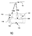
撮像システム100に基づいた本発明の第1の一般的な実施形態は、図3aに示されている。その粗調タイミング図は、図3bに示されており、微調タイミング図は、図3cに示されている。撮像システムは、図1aに示された飛行時間型ピクセルからなる飛行時間型撮像センサ110と、照明光源120と、光学系130と、制御部140とを含む。出射光120aは、対象物10によって反射される。後方反射光120bは、光学系130により飛行時間型撮像センサ110上に結像される。飛行時間型撮像センサ110および照明光源120は、制御部140によって時間的に変調および同期される。よって、照射源120がオンにされている間に、飛行時間型撮像センサ110上の飛行時間型ピクセルの1つの記憶ノードは、すべての光生成電子を積算し、照明光源120がオフされている間に、第2の記憶ノードは、すべての光生成電子を収集する。このオン/オフサイクルは、複数回に繰り返されてもよい。本発明は、出射光および後方反射光の飛行時間に対する実際の影響を無視することができ、すべての出射光を飛行時間型撮像センサの各ピクセルの単一の記憶ノードに好ましく捕捉するように、このような低い変調周波数を高速飛行時間型撮像センサおよびピクセルに適用することを提案する。また、図3bに示すように、本発明は、現行の飛行時間測定値を導き出すことができない程のより少ないサンプル数および取得回数を取得することを提案している。第1の露光Eの後、読み出しROを行う。露光Eの間に、光生成電荷は、記憶ノードC1または記憶ノードC2に転送され、照明光源120と同期される。所定の実施形態において、TOF情報を導き出すためのすべての必要(少なくとも3つ)のサンプルを収集するために必要とされた取得回数を少なくとも2回または4回ではなく1回にすることを提案した。時間Dにおいて、サンプルの数は、捕捉した信号の飛行時間情報を推定することはできない。本発明の変形例としての単一露光例において、2つのサンプルの差分撮影が行われる。図3aに示唆したように、擬似ランダム方法で変調を行うことができる。これにより、異なる撮像システム100の間の干渉を最小化することができる。擬似ランダムコーディングの他に、他の既知の技術、たとえば相ホッピングまたは周波数ホッピング、チャープまたは他の分割多重アクセス手法を実行することによって、システムの干渉を最小化することができる。
A first general embodiment of the present invention based on the
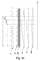
図3cは、図3bに示された単一露光のタイミング図をより詳細に示している。図3cの場合、積算中に、2つの記憶ノードC1およびC2を互いに減算する回路を含む。Fは、総フレームを表し、Eは、実際の露光を表し、ROは、読み出し時間を表し、RSは、リセット時間をを表す。本実施形態の現在タイミングにおける変調周波数は、合理的な飛行時間撮像を行うために必要とされた変調周波数よりもはるかに低い。光L1は、照明光源120によって出射され、飛行時間型撮像センサ110と同期される。よって、「点灯」時に、すべての光生成電荷が第1の記憶ノードC1に転送され、「消灯」時に、すべての光生成電荷が第2の記憶ノードC2に転送される。時間tに亘って後方に反射され受信された光信号は、L2として描かれ、いくつかの背景光成分LBGを有する。S1は、「点灯」時に第1の記憶ノードC1に対する積算を示し、S2は、「消灯」時に記憶ノードC2に対する積算を示す。Sdiffは、現行のインピクセル背景除去を実施したときの信号差分を示している。インピクセル回路Cは、差分を構築することによって、背景光信号を除去する。図示の例において、飛行時間型撮像センサ110上の飛行時間型ピクセルは、積算中に、Sdiffに基づき、2つのノードの直接減算を行う。他の実現例において、飛行時間型ピクセルは、積算時間の終了時に減算を行う。両方の実現例は、能動撮像システムの動作範囲を増大する。露光Eの間に、「点灯」および「消灯」は、複数回に繰り返される。数百Hz〜1MHz範囲に位置する変調周波数は、光パルスの到達時間に与える影響を軽減することができる。同一量の背景光を飛行時間型撮像センサ110のピクセル上の第1の記憶ノードC1および第2の記憶ノードC2に積算し、サンプルから同一の背景レベルまたは共通モードレベルを減算するために、好ましくは、露光中に飛行時間型ピクセルの第1の記憶ノードC1および第2の記憶ノードC2の両方の総積算時間を同等にする。両方の露光時間を同一にした場合、光パルスは、その記憶ノードに転送されるサンプリング期間よりも短くなる可能性がある。これにより、パルスの到着時間に影響を与えないことがさらに保証される。いずれの場合、できる限り最大の背景光除去を達成するために、2つの記憶ノードへの総露光時間を同一に維持すべきだろう。露光量Eの後、ピクセル値に読み出しROを行い、読み出されたピクセル値は、制御部140に転送される。、一般的には、次回の取得を開始する前に、ピクセルに対してリセットRSを行う。2つの記憶ノードの光応答における不整合を低減するために、撮像センサのピクセルの光反応に応じて、第1の露光Eに比べて第2の露光を逆にスイッチングし、2つの画像を減算することは、有益であり得る。しかしながら、取得されたサンプルの数は、依然として飛行時間情報を導き出すのに十分ではないであろう。
FIG. 3c shows in more detail the timing diagram for the single exposure shown in FIG. 3b. 3c includes a circuit that subtracts the two storage nodes C1 and C2 from each other during integration. F represents the total frame, E represents the actual exposure, RO represents the readout time, and RS represents the reset time. The modulation frequency at the current timing of this embodiment is much lower than the modulation frequency required to perform reasonable time-of-flight imaging. The light L1 is emitted by the
図4は、本発明に係る撮像システム100を示している。撮像システム100は、図1aに示された飛行時間型ピクセルからなる飛行時間型撮像センサ110と、光学系130と、構造化照明光源121と、制御部140とを含む。制御部140は、飛行時間型撮像センサ110および構造化照明光源121を同期し、時間的に変調する。構造化照明光源121は、時間変調された光121aを出射する。光121aは、対象物10によって反射される。シーン10によって後方に反射された光121は、光学系130によって飛行時間型撮像センサ110上に投光される。そこで、飛行時間型ピクセルは、入射信号を2つの2つの記憶ノードに復調する。撮像システム100のタイミングは、図3に記載のものと同様であってもよい。PCT公開WO2007/105205A2により提示されたように、構造化照明光源および3次元マッピング技術を適用することができる。WO2007/105205A2に記載されたように、構造化照明光源には、干渉によって生じたスペックルに基づいた投光技術を適用することができる。しかしながら、たとえば屈折に基づく光学系またはパターン生成マスクを用いた他の投光技術を構造化照明光源121に適用することもできる。好ましくは、ランダムドットパターンの光を投光する。欧州特許出願EP2519001A2は、第1および第2の記憶ノードへの転送ゲートを有する特別に設計されたセンサピクセルを備えるセンサに基づき、標準の低速フォトダイオードを用いる構造化光システムの使用を教示した。対照的に、本発明は、特別設計のピクセルを使用せず、既存の高速飛行時間型撮像センサ110およびピクセルを使用して、制御部140によって光の実際の走行時間(飛行時間)に与える影響を無視できる程度の低い変調周波数を構造化照明光源121および飛行時間型撮像センサ110に適用して、撮像センサ110上で後方に反射された光121bのサンプリングおよび格納を行うことを提案している。また、提案された飛行時間型撮像センサ110は、少なくとも3つの必要なサンプルを捕捉せず、飛行時間型撮像センサ110からのサンプルをより少ない数で評価するモードで動作する。現行の飛行時間型撮像システムに必要とされた典型的な90°の位相シフトが採用されず、飛行時間型撮像センサ110上のすべてのピクセルの2つの記憶ノードから生じた差分画像のみが評価される。前述したすべての高速飛行時間型撮像センサは、現行の飛行時間測定システムに使用できないような低周波数で、反射光を少なくとも2つの記憶ノードに時間的に復調することができる。また、前述したすべての高速飛行時間型撮像センサは、飛行時間型撮像に必要とされたサンプル数よりも少ない数のサンプルを取得することができる。したがって、前述したすべてのピクセル設計は、本発明に係る飛行時間型撮像センサとして組み込むことができる。適切なインピクセル回路を備えれば、飛行時間型撮像センサ110は、サンプルから共通信号レベルを減算し、または単に2つの記憶ノードのサンプルを互いに減算することができる。これにより、一方では、撮像システムの動作範囲を増加することができ、他方では、動的背景光信号が画像から除去されるため、深度マッピング用の相関アルゴリズムを簡略化することができる。さらに、コードまたは周波数分割多重アクセスなどの適切な時間変調方式を適用することによって、3次元撮像システムの異なる構造光の妨害干渉を回避することができる。
FIG. 4 shows an
理想的には、飛行時間型撮像センサ110の飛行時間型ピクセルは、「点灯」時間中に電荷を第1の記憶ノードに転送し、「消灯」時間中に電荷を第2の記憶ノードに転送して、減算を行う。時間変調および飛行時間型ピクセルの背景キャンセル回路は、上記のすべての利点を構造化光システムに追加する。変調周波数は、好ましくは、現行のTOF測定に対して低すぎる数百Hzから1MHzまでの範囲内にある。図4に記載されたように、このような撮像システム100は、構造化照明光源121と飛行時間型センサ100とを含み、構造化照明光源121と飛行時間型センサ100との両方が飛行時間による撮像に必要とされた変調周波数よりも低い変調周波数で動作するため、PCT公開WO2007/105205A2および/またはWO2014/014341A1に記載したように、この撮像システム100は、既存の3次元撮像装置の動作範囲を大幅に増加する。
Ideally, the time-of-flight pixel of the time-of-
図5は、疲労センサとして使用される本発明の撮像システム100を示している。本実施形態によれば、たとえば運転者の眠気測定または疲労推定に使用されることのできる非常に強固な眼追跡システムを構築することができる。本発明の撮像システム100は、各々が近赤外域に波長を有する2つの異なる照明光源を含む。第1の照明光源122は、たとえば約850nmに位置する第1の波長を有し、第2の照明光源123は、たとえば約940nmに位置する第2の波長を有する。本発明の撮像システム100は、図1aの飛行時間型ピクセルを有する飛行時間型撮像センサ110と、光学系130と、制御部140とをさらに含む。両方の照明光源122および123は、制御部140によって飛行時間型撮像センサ110と同期される。露光中に、第1の波長を有する第1の照明光源122がオンにされると、第2の波長を有する第2の照明光源123がオフにされ、その逆も同様である。第1の波長を有する第1の照明光源122は、光122aを出射し、第2の波長を有する第2の照明光源123は、光123aを出射する。第1の波長を有する第1の照明光源122の後方反射光122bは、光学系130により飛行時間型撮像センサ110の飛行時間型ピクセル上で結像し、飛行時間型ピクセルの第1の記憶ノードに転送される。第2の波長を有する第2の照明光源123の後方反射光123bは、同一の飛行時間型撮像センサ110により捕捉され、飛行時間型ピクセルの第2の記憶ノードに転送される。露光後、差分読み出しまたはオンピクセル信号減算を行うことによって、2つの照明光源の差分画像を直接測定することができる。人間の目の網膜が約850nmで直接反射を示し、約940nmで大幅に減少した反射を示すため、差分画像から瞳孔をはっきり見ることができ、瞳孔を簡単かつロバストに追跡することができる。差分画像から瞳孔を容易に識別することができ、眼の開閉を容易に検出することができる。眼の瞬きに基づき、たとえばバス運転手のPERCLOS値(一分間に目が80%閉じている時間の割合/百分率)または眠気係数を測定することができ、対応する行動をとることができる。Hammoudらによって米国特許出願US7253739B2に記載されたように、運転者の眠気を決定する最新の方法は、主に標準撮像および煩雑な画像処理に基づき、運転者の眠気を決定する。
FIG. 5 shows an
図6に示された撮像システム105の実施形態は、本発明の3次元撮像システムを例示している。撮像システム105は、異なる構造種類の第1の構造化照明光源121と第2の構造化照明光源125とを含む。両方の照明光源は、近赤外波長を有する。また、この撮像システムは、撮像センサ115と、光学系130と、制御部140とを含む。システム105は、第1の構造化照明光源121と第2構造化照明光源125とを用いて、両方の照明光源を撮像センサ115の隣りに配置することによって構築される。制御部140は、構造化照明光源121、125および撮像センサ115を同期する。2つの照明光源121および125は、好ましくは、閉塞を最小化するように配置される。第1の構造化照明光源121からの出射光121aは、反射され、後方反射光121bは、光学系130によって撮像センサ115に投光される。同様に、第2の構造化照明光源125からの出射光125aは、反射され、後方反射光125bは、同一の光学系130によって同一の撮像センサ115に投光される。画像取得中に、照明光源121および125は、時間変調されてもよい。この場合、照明光源121および125は、第1の構造化照明光源121からのすべての光が撮像センサ115のピクセルの第1の記憶ノードに収集され、第2の構造化照明光源125からの後方反射光125bが撮像センサ115のピクセルの第2の記憶ノードに収集されることができるように、好ましくは露光中に反転される。時間変調として、たとえば方形波、擬似雑音などを使用してもよい。撮像センサ115のピクセルが背景減算回路を含む場合、第1の構造化照明光源121からの信号が正となり、第2の構造化照明光源125からの信号が負となる。2つの照明光源を物理的に分離し、時間的に交互に扱うこの手法の欠点は、第1の構造化照明光源121および第2の構造化照明光源125からの信号を含むピクセルが互いにキャンセルする可能性があることである。したがって、たとえば、ランダムスペックルパターンを有するように第1の構造化照明光源121を設計し、ストライプパターンを有するように第2の構造化照明光源125を設計することは、考えられる。また、両方の構造化照明光源を構成化パターンとして同一の発光ダイ、たとえばVCSELアレイに集積化することも考えられる。VCSELアレイは、同一のVCSELアレイダイ上に設けられ、別々に制御されることができる2つのグループの発光レーザダイオード、すなわち、第1の構造化照明光源121に対応する第1のグループの発光レーザダイオードと、第2の構造化照明光源125に対応する第2のグループの発光レーザダイオードとから構成されてもよい。同一のダイ上に設けられ、構造化照明光源に基づいた撮像システムの投光器として使用されるVCSELアレイ、および単一の駆動信号を用いてアレイの全体を制御することは、米国特許出願US2013038881A1に開示されている。しかしながら、第1のグループのレーザダイオード発光スポットをダイ上にランダムに配置し、第2のグループのレーザダイオード発光スポットを第1のグループのレーザダイオード発光スポットと同一のパターンでわずかなシフトすることによって同一のダイに配置することも考えられる。このVCSELアレイのパターンに投光することによって、第1のグループのレーザダイオードまたは第1の構造化照明光源121から投光されるスポットおよび第2のグループのレーザダイオードまたは第2の構造化照明光源125から投光されるスポットは、VCSELアレイダイ上で物理的に分離されているため、空間上互いに干渉しない。スポットからの出射光は、同一の投光光学系によって空間に投光される。また、2つのグループのレーザダイオードは、第1の構造化照明光源121のすべての後方反射光121bが撮像センサ115のピクセルの第1の記憶ノードに記憶され、第2の構造化照明光源125のすべての後方反射光125bが撮像センサ115のピクセルの第2の記憶ノードに記憶されるように、制御されることができる。また、動作範囲を増大するために、撮像センサ115のピクセルは、背景光キャンセル回路を含んでもよい。さらに、撮像センサ115は、飛行時間型撮像センサ110であってもよい。
The embodiment of the
図7a〜7dは、本発明の撮像システム105の一実施形態を示している。本発明の撮像システム105は、構造化照明光源121と、均一照明光源126と、光学系130と、撮像センサ115と、制御部140とを含む。両方の照明光源は、近赤外域に波長を有する。図7aに示すように、第1の露光中に、構造化照明光源121は、オンにされ、均一照明光源は、オフにされる。図7aにより示唆したように、構造化照明光源121は、制御部140によって変調され、撮像センサ115と同期することができる。構造化照明光源121からの出射光121aは、対象物10に到達してから反射される。構造化照明光源121からの後方反射光121bは、光学系130によって撮像センサ115上に結像される。撮像センサ115により捕捉された構造化照明光源121の画像は、従来の方法に使用され、シーンから深度情報を導き出すことができる。しかしながら、構造化照明光源121に基づいた撮像センサ115から提供されたグレースケール取得画像は、代表的なものではなく、多くの場合に対象物および詳細をはっきり視認できない。ランダムドットパターンを有する構造化照明光源121に基づいて得られたこのようなグレースケール画像は、図7cに示されている。細部の損失がはっきり見える。それでも通常画像を得られるように、構造化照明光源に基づいた最新の撮像システムは、独自の光路を有する第2の撮像装置を第1の撮像センサ115の隣りに追加する。第2の撮像センサは、一般的には、RGBセンサであり、完全に独立したカラー画像を提供する。しかしながら、異なる光路を介して第2の画像を取得することは、第1に高価になり、第2に2つの画像のマッピングが多くの課題に面する。本発明の方法の実施形態は、均一照明光源126をオンにし、同一の光学系130と撮像センサ115とを使用して、撮像システム105による第2の画像を取得することを提案した。均一照明光源126からの出射光126aは、シーン内の対象物10に達すると、反射される。均一照明光源126からの後方反射光126bは、光学系130によって撮像センサ115上に結像される。第2の画像の取得動作は、図7bに示されている。図7bにより示唆されたように、均一照明光源126と撮像センサ115とは、制御部140によって同期され、変調されることができる。均一照明光源126に基づいて得られたこの第2の画像のグレースケール画像は、図7dに示されている。その詳細は、よりはっきり視認することができるため、構造化照明光源121および均一照明光源126からのグレースケール画像からの3次元画像のマッピングは、簡単になる。
7a-7d show one embodiment of the
適切な帯域通過光学フィルタを光学系130に実装するためには、構造化照明光源121と均一照明光源126とが同様の波長を有することが有利である。また、制御部140を用いて、構造化照明光源121および均一照明光源126を撮像センサ115と同期し、変調することができる。動作範囲を増加するために、撮像センサ115は、インピクセル背景キャンセル回路をさらに有することができる。
In order to implement a suitable bandpass optical filter in the
また、撮像センサ115は、飛行時間型撮像センサ110であってもよい。
図8は、本発明の実際の実施形態を示している。撮像システム105は、光学系130と、構造化照明光源121と、均一照明光源126とを含む。各照明光源は、近赤外域に波長を有する。光学系の後方にある撮像センサ115と制御部140とは、撮像システム105の筐体の後方に隠されているため、図面から見ることができない。図8に与えられた例において、均一照明光源126は、中央に配置された構造化照明光源126の近隣に配置された2つの同様の照明光源から構成される。均一照明光源126に基づき、撮像センサ115によって撮像された画像は、シーンの代表的なグレースケール図として使用されることができる一方、構造化照明光源121に基づき、撮像センサ115によって撮像された画像は、三角測量の原理に基づき、深度情報を導き出すために使用されることができる。光学系130に実装された狭帯域通過フィルタが構造化照明光源121および均一照明光源126からの光をできるだけ多く通過して撮像センサ115上に到達するとともに、可能な限り多くの背景光を遮断することを可能にするために、構造化照明光源121の波長および均一照明光源126の波長は、好ましくは同様である。また、図7で説明したように、撮像センサ115と構造化照明光源121とは、同期化され、変調されてもよい。また、図7で説明したように、均一照明光源126と撮像センサ115とは、同期され変調されてもよい。さらに、撮像センサ115は、飛行時間型撮像センサ110であってもよいが、好ましくはインピクセル背景キャンセル回路を含む。均一照明光源126に基づいて得られた画像に基づき、適切な画像処理アルゴリズムは、構造化照明光源121に基づいて得られた画像を評価することによって再構成された深度マップを改善することができる。
The
FIG. 8 shows an actual embodiment of the present invention. The
前述の変調照明光源を備える実装形態のすべてにおいて、光源パルスは、好ましくは、記憶ノードのうち1つに対するサンプリング期間と同一またはそれより短い持続時間を有する。さらに、両方の記憶ノード内に同等の背景光をキャンセルするために、記憶ノードのサンプリング期間は、好ましくは、2つのノードに対して等しい。 In all implementations comprising a modulated illumination light source as described above, the light source pulses preferably have a duration that is the same as or shorter than the sampling period for one of the storage nodes. Furthermore, in order to cancel the equivalent background light in both storage nodes, the storage node sampling period is preferably equal for the two nodes.
構造化照明光源は、固定のパターンで発光する空間的に変調する光源として理解される。可能なパターンは、スペックルパターン(ランダム、擬似ランダムまたは通常)、ストライプパターン、ランダムバイナリパターンなどを含む。 A structured illumination light source is understood as a spatially modulated light source that emits light in a fixed pattern. Possible patterns include speckle patterns (random, pseudo-random or normal), stripe patterns, random binary patterns, and the like.
Claims (40)
前記撮像システム(105)は、各々が近赤外域に波長を有する少なくとも2つの異なる照明光源によって照明されるシーンの画像を処理するように構成されている、撮像システム(105)。 An imaging system (105) including an imaging sensor (115),
The imaging system (105) is configured to process images of a scene illuminated by at least two different illumination sources, each having a wavelength in the near infrared region.
各々が近赤外域に波長を有する少なくとも2つの異なる照明光源によって照明されるシーンの画像が処理されることを特徴とする、撮像方法。 An imaging method using an imaging sensor (115),
An imaging method characterized in that images of a scene illuminated by at least two different illumination sources, each having a wavelength in the near infrared region, are processed.
前記撮像システム(100)は、飛行時間の測定に使用された変調周波数よりも低い変調周波数を有する照明光源(120)を使用するように構成されていることを特徴とする、撮像システム(100)。 An imaging system (100) including a time-of-flight sensor (110),
The imaging system (100), wherein the imaging system (100) is configured to use an illumination light source (120) having a modulation frequency that is lower than the modulation frequency used to measure time of flight. .
飛行時間の測定に使用された変調周波数よりも低い変調周波数を有する照明光源(120)を使用することを特徴とする、撮像方法。 An imaging method using a time-of-flight sensor (110),
An imaging method, characterized in that an illumination light source (120) having a modulation frequency lower than the modulation frequency used for time-of-flight measurement is used.
前記撮像システムは、飛行時間の測定に必要とされたフレーム単位サンプル数よりも少ないフレーム単位サンプル数を取得することを特徴とする、撮像システム(100)。 An imaging system (100) including a time-of-flight sensor (110),
The imaging system (100), wherein the imaging system acquires a number of frame-unit samples that is smaller than the number of frame-unit samples required for measurement of time of flight.
飛行時間の測定に必要とされたフレーム単位サンプル数よりも少ないフレーム単位サンプル数を取得することを特徴とする、撮像方法。 An imaging method using a time-of-flight sensor (110),
An imaging method characterized by acquiring a number of frame-unit samples that is smaller than the number of frame-unit samples required for measuring time of flight.
Priority Applications (1)
| Application Number | Priority Date | Filing Date | Title |
|---|---|---|---|
| JP2019075455A JP6983192B2 (en) | 2013-06-06 | 2019-04-11 | Imaging system and how to operate it |
Applications Claiming Priority (3)
| Application Number | Priority Date | Filing Date | Title |
|---|---|---|---|
| US201361831647P | 2013-06-06 | 2013-06-06 | |
| US61/831,647 | 2013-06-06 | ||
| PCT/EP2014/001526 WO2014195020A1 (en) | 2013-06-06 | 2014-06-05 | Sensor system with active illumination |
Related Child Applications (1)
| Application Number | Title | Priority Date | Filing Date |
|---|---|---|---|
| JP2019075455A Division JP6983192B2 (en) | 2013-06-06 | 2019-04-11 | Imaging system and how to operate it |
Publications (2)
| Publication Number | Publication Date |
|---|---|
| JP2016524709A true JP2016524709A (en) | 2016-08-18 |
| JP2016524709A5 JP2016524709A5 (en) | 2017-07-20 |
Family
ID=50942645
Family Applications (2)
| Application Number | Title | Priority Date | Filing Date |
|---|---|---|---|
| JP2016517191A Pending JP2016524709A (en) | 2013-06-06 | 2014-06-05 | Sensor system with active illumination |
| JP2019075455A Active JP6983192B2 (en) | 2013-06-06 | 2019-04-11 | Imaging system and how to operate it |
Family Applications After (1)
| Application Number | Title | Priority Date | Filing Date |
|---|---|---|---|
| JP2019075455A Active JP6983192B2 (en) | 2013-06-06 | 2019-04-11 | Imaging system and how to operate it |
Country Status (7)
| Country | Link |
|---|---|
| US (1) | US10401498B2 (en) |
| EP (1) | EP3004924B1 (en) |
| JP (2) | JP2016524709A (en) |
| KR (1) | KR102203318B1 (en) |
| CN (1) | CN105705962B (en) |
| SG (2) | SG11201509788QA (en) |
| WO (1) | WO2014195020A1 (en) |
Cited By (5)
| Publication number | Priority date | Publication date | Assignee | Title |
|---|---|---|---|---|
| JP2019533134A (en) * | 2017-08-14 | 2019-11-14 | シェンチェン グディックス テクノロジー カンパニー,リミテッド | Three-dimensional imaging system and electronic device |
| JP2020101377A (en) * | 2018-12-20 | 2020-07-02 | 三星電子株式会社Samsung Electronics Co.,Ltd. | Three-dimensional information calculation device, three-dimensional measurement device, three-dimensional information calculation method, and three-dimensional information calculation program |
| JP2020109977A (en) * | 2020-02-28 | 2020-07-16 | シェンチェン グディックス テクノロジー カンパニー,リミテッド | Three-dimensional imaging system and electronic device |
| WO2021172070A1 (en) * | 2020-02-26 | 2021-09-02 | 株式会社デンソー | Optical detection device and method for determining optical axis offset in optical detection device |
| JP2021135292A (en) * | 2020-02-26 | 2021-09-13 | 株式会社デンソー | Optical detector and method for determining displacement of optical axis in optical detector |
Families Citing this family (40)
| Publication number | Priority date | Publication date | Assignee | Title |
|---|---|---|---|---|
| KR102311688B1 (en) | 2015-06-17 | 2021-10-12 | 엘지전자 주식회사 | Mobile terminal and method for controlling the same |
| WO2016204363A1 (en) | 2015-06-17 | 2016-12-22 | Lg Electronics Inc. | Mobile terminal and method for controlling the same |
| DE102015010421A1 (en) | 2015-08-11 | 2017-02-16 | Daimler Ag | Three-dimensional detection of the vehicle interior |
| US10101154B2 (en) * | 2015-12-21 | 2018-10-16 | Intel Corporation | System and method for enhanced signal to noise ratio performance of a depth camera system |
| EP3232224B1 (en) * | 2016-04-12 | 2018-06-13 | Sick Ag | Distance-measuring opto-electronic sensor and method for detecting and determining the distance from objects |
| US10924638B2 (en) | 2016-06-27 | 2021-02-16 | Intel Corporation | Compact, low cost VCSEL projector for high performance stereodepth camera |
| US20180064399A1 (en) * | 2016-09-07 | 2018-03-08 | Heptagon Micro Optics Pte. Ltd. | Imaging systems including multi-tap demodulation pixels for biometric measurements |
| US10627494B2 (en) * | 2016-09-16 | 2020-04-21 | Analog Devices, Inc. | Interference handling in time-of-flight depth sensing |
| DE102016219099A1 (en) * | 2016-09-30 | 2018-04-05 | Robert Bosch Gmbh | Optical sensor for distance and / or speed measurement, system for mobility monitoring of autonomous vehicles and method for monitoring the mobility of autonomous vehicles |
| EP3301479A1 (en) | 2016-10-03 | 2018-04-04 | Xenomatix NV | Method for subtracting background light from an exposure value of a pixel in an imaging array, and pixel for use in same |
| US10582178B2 (en) * | 2016-11-02 | 2020-03-03 | Omnivision Technologies, Inc. | Systems and methods for active depth imager with background subtract |
| US10771768B2 (en) | 2016-12-15 | 2020-09-08 | Qualcomm Incorporated | Systems and methods for improved depth sensing |
| WO2018139237A1 (en) * | 2017-01-25 | 2018-08-02 | 国立研究開発法人産業技術総合研究所 | Image processing method |
| CN106934394B (en) * | 2017-03-09 | 2024-01-19 | 奥比中光科技集团股份有限公司 | Dual wavelength image acquisition system and method |
| US10445893B2 (en) | 2017-03-10 | 2019-10-15 | Microsoft Technology Licensing, Llc | Dot-based time of flight |
| US10928489B2 (en) * | 2017-04-06 | 2021-02-23 | Microsoft Technology Licensing, Llc | Time of flight camera |
| US10401956B2 (en) | 2017-05-11 | 2019-09-03 | Microsoft Technology Licensing, Llc | Infrared eye-tracking in high ambient light conditions |
| US10613228B2 (en) | 2017-09-08 | 2020-04-07 | Microsoft Techology Licensing, Llc | Time-of-flight augmented structured light range-sensor |
| CN107607957B (en) * | 2017-09-27 | 2020-05-22 | 维沃移动通信有限公司 | Depth information acquisition system and method, camera module and electronic equipment |
| US10215856B1 (en) | 2017-11-27 | 2019-02-26 | Microsoft Technology Licensing, Llc | Time of flight camera |
| US11675048B2 (en) * | 2017-11-30 | 2023-06-13 | Sony Semiconductor Solutions Corporation | Time-of-flight acquisition method and time-of-flight camera |
| US11543525B2 (en) * | 2017-12-22 | 2023-01-03 | Sony Semiconductor Solutions Corporation | Signal generation apparatus |
| WO2019123830A1 (en) | 2017-12-22 | 2019-06-27 | ソニーセミコンダクタソリューションズ株式会社 | Signal generator |
| US11592536B2 (en) * | 2018-01-10 | 2023-02-28 | Sony Semiconductor Solutions Corporation | Control of image capture |
| US10901087B2 (en) | 2018-01-15 | 2021-01-26 | Microsoft Technology Licensing, Llc | Time of flight camera |
| DE102018204902A1 (en) | 2018-03-29 | 2019-10-02 | Zf Friedrichshafen Ag | Functional safety for a three-dimensional interior camera |
| US10663567B2 (en) | 2018-05-04 | 2020-05-26 | Microsoft Technology Licensing, Llc | Field calibration of a structured light range-sensor |
| JP2020031120A (en) * | 2018-08-22 | 2020-02-27 | ソニーセミコンダクタソリューションズ株式会社 | Light source device, temperature detection method and sensing module |
| DE102018215513A1 (en) | 2018-09-12 | 2020-03-12 | Zf Friedrichshafen Ag | Arrangement of TOF sensors for detecting a passenger room of a people mover, evaluation device for perceiving a passenger room of a people mover and perception system for detecting a blocking of a passenger door of a people mover, a number of passengers in the people mover and of positions, body poses and activities of the passengers |
| EP3640677B1 (en) | 2018-10-17 | 2023-08-02 | Trimble Jena GmbH | Tracker of a surveying apparatus for tracking a target |
| EP3640590B1 (en) | 2018-10-17 | 2021-12-01 | Trimble Jena GmbH | Surveying apparatus for surveying an object |
| EP3696498A1 (en) | 2019-02-15 | 2020-08-19 | Trimble Jena GmbH | Surveying instrument and method of calibrating a survey instrument |
| CN109916279B (en) * | 2019-03-04 | 2020-09-22 | Oppo广东移动通信有限公司 | Flatness detection method and device for terminal cover plate, test machine table and storage medium |
| WO2021030034A1 (en) | 2019-08-15 | 2021-02-18 | Apple Inc. | Depth mapping using spatial multiplexing of illumination phase |
| US11474249B2 (en) * | 2019-08-29 | 2022-10-18 | Wisconsin Alumni Reseach Foundation | Systems, methods, and media for stochastic exposure coding that mitigates multi-camera interference in continuous wave time-of-flight imaging |
| US11592568B2 (en) | 2019-10-18 | 2023-02-28 | Ai4 International Oy | Measurement device and method of operating therefor |
| US20210262787A1 (en) * | 2020-02-21 | 2021-08-26 | Hamamatsu Photonics K.K. | Three-dimensional measurement device |
| US11763472B1 (en) | 2020-04-02 | 2023-09-19 | Apple Inc. | Depth mapping with MPI mitigation using reference illumination pattern |
| US11558569B2 (en) | 2020-06-11 | 2023-01-17 | Apple Inc. | Global-shutter image sensor with time-of-flight sensing capability |
| CN112379389B (en) * | 2020-11-11 | 2024-04-26 | 杭州蓝芯科技有限公司 | Depth information acquisition device and method combining structured light camera and TOF depth camera |
Citations (6)
| Publication number | Priority date | Publication date | Assignee | Title |
|---|---|---|---|---|
| JP2002123837A (en) * | 2000-08-30 | 2002-04-26 | Microsoft Corp | Method and system for animating feature of face, and method and system for expression transformation |
| JP2006071784A (en) * | 2004-08-31 | 2006-03-16 | Tokyo Seimitsu Co Ltd | Confocal microscope, outside appearance inspecting device and semiconductor outside appearance inspecting device |
| JP2010091569A (en) * | 2008-10-13 | 2010-04-22 | Koh Young Technology Inc | Method and apparatus of measuring three-dimensional shape |
| JP2011027707A (en) * | 2009-06-25 | 2011-02-10 | Sharp Corp | Person motion detecting device, play apparatus, person motion detecting method, gaming method, control program, and readable recording medium |
| JP2011520116A (en) * | 2008-05-09 | 2011-07-14 | フリーイェ・ユニヴェルシテイト・ブリュッセル | TOF region advantageous for suppression of background radiation |
| US20130002823A1 (en) * | 2011-06-28 | 2013-01-03 | Samsung Electronics Co., Ltd. | Image generating apparatus and method |
Family Cites Families (29)
| Publication number | Priority date | Publication date | Assignee | Title |
|---|---|---|---|---|
| JPS60174905A (en) * | 1984-02-22 | 1985-09-09 | Hitachi Ltd | Distance measuring apparatus |
| BR9712804B1 (en) * | 1996-09-05 | 2011-04-19 | Method and apparatus for determining the phase and / or amplitude information of an electromagnetic wave. | |
| JP2917953B2 (en) * | 1997-02-05 | 1999-07-12 | 日本電気株式会社 | View point position detection device |
| WO2001031570A2 (en) * | 1999-10-27 | 2001-05-03 | Digital Ink, Inc. | Tracking motion of a writing instrument |
| US7420148B2 (en) | 2002-09-13 | 2008-09-02 | Conti Temic Microelectronic Gmbh | Method and device for determining a pixel gray scale value image |
| JP4161910B2 (en) * | 2004-01-28 | 2008-10-08 | 株式会社デンソー | Distance image data generation device, generation method, and program |
| US7583863B2 (en) * | 2004-05-10 | 2009-09-01 | Avago Technologies General Ip (Singapore) Pte. Ltd. | Method and system for wavelength-dependent imaging and detection using a hybrid filter |
| WO2007105205A2 (en) * | 2006-03-14 | 2007-09-20 | Prime Sense Ltd. | Three-dimensional sensing using speckle patterns |
| US7586077B2 (en) * | 2007-07-18 | 2009-09-08 | Mesa Imaging Ag | Reference pixel array with varying sensitivities for time of flight (TOF) sensor |
| EP2026097A1 (en) * | 2007-08-08 | 2009-02-18 | Harman Becker Automotive Systems GmbH | Vehicle illumination system |
| JP2009180690A (en) * | 2008-02-01 | 2009-08-13 | Nikon Corp | Three-dimensional shape measuring apparatus |
| CN102027388B (en) | 2008-04-11 | 2013-08-28 | 瑞士联邦理工大学,洛桑(Epfl) | Time-of-flight based imaging system using a display as illumination source |
| JP2010002326A (en) * | 2008-06-20 | 2010-01-07 | Stanley Electric Co Ltd | Movement vector detector |
| WO2010021090A1 (en) * | 2008-08-20 | 2010-02-25 | パナソニック株式会社 | Distance estimating device, distance estimating method, program, integrated circuit, and camera |
| JP2010219436A (en) * | 2009-03-18 | 2010-09-30 | Sony Corp | Multi-wavelength semiconductor laser and optical recording and reproducing device |
| JP5799211B2 (en) * | 2009-04-24 | 2015-10-21 | パナソニックIpマネジメント株式会社 | Distance image sensor |
| JP5469446B2 (en) * | 2009-12-22 | 2014-04-16 | パナソニック株式会社 | Object detection device |
| JP5740413B2 (en) * | 2010-01-06 | 2015-06-24 | メサ・イメージング・アー・ゲーMesa Imaging Ag | Demodulation sensor with separate pixel array and storage array |
| JP2012002780A (en) * | 2010-06-21 | 2012-01-05 | Shinko Electric Ind Co Ltd | Shape measurement instrument, shape measurement method, and semiconductor package manufacturing method |
| JP5671281B2 (en) * | 2010-08-20 | 2015-02-18 | キヤノン株式会社 | Position / orientation measuring apparatus, control method and program for position / orientation measuring apparatus |
| KR101753312B1 (en) * | 2010-09-17 | 2017-07-03 | 삼성전자주식회사 | Apparatus and method for generating depth image |
| EP2477043A1 (en) * | 2011-01-12 | 2012-07-18 | Sony Corporation | 3D time-of-flight camera and method |
| GB2490872B (en) * | 2011-05-09 | 2015-07-29 | Toshiba Res Europ Ltd | Methods and systems for capturing 3d surface geometry |
| KR101799522B1 (en) * | 2011-06-07 | 2017-11-21 | 삼성전자 주식회사 | 3D image acquisition apparatus employing interchangeable lens type |
| TWI575494B (en) * | 2011-08-19 | 2017-03-21 | 半導體能源研究所股份有限公司 | Method for driving semiconductor device |
| JP2014207493A (en) * | 2011-08-24 | 2014-10-30 | パナソニック株式会社 | Imaging apparatus |
| US8982363B2 (en) * | 2011-10-07 | 2015-03-17 | Massachusetts Institute Of Technology | Method and apparatus to determine depth information for a scene of interest |
| JP2013096941A (en) * | 2011-11-04 | 2013-05-20 | Sony Corp | Imaging device, imaging method, and program |
| US9046359B2 (en) * | 2012-05-23 | 2015-06-02 | Jds Uniphase Corporation | Range imaging devices and methods |
-
2014
- 2014-06-05 CN CN201480032296.3A patent/CN105705962B/en active Active
- 2014-06-05 WO PCT/EP2014/001526 patent/WO2014195020A1/en active Application Filing
- 2014-06-05 US US14/895,068 patent/US10401498B2/en active Active
- 2014-06-05 EP EP14730078.4A patent/EP3004924B1/en active Active
- 2014-06-05 KR KR1020167000211A patent/KR102203318B1/en active IP Right Grant
- 2014-06-05 JP JP2016517191A patent/JP2016524709A/en active Pending
- 2014-06-05 SG SG11201509788QA patent/SG11201509788QA/en unknown
- 2014-06-05 SG SG10201710025WA patent/SG10201710025WA/en unknown
-
2019
- 2019-04-11 JP JP2019075455A patent/JP6983192B2/en active Active
Patent Citations (6)
| Publication number | Priority date | Publication date | Assignee | Title |
|---|---|---|---|---|
| JP2002123837A (en) * | 2000-08-30 | 2002-04-26 | Microsoft Corp | Method and system for animating feature of face, and method and system for expression transformation |
| JP2006071784A (en) * | 2004-08-31 | 2006-03-16 | Tokyo Seimitsu Co Ltd | Confocal microscope, outside appearance inspecting device and semiconductor outside appearance inspecting device |
| JP2011520116A (en) * | 2008-05-09 | 2011-07-14 | フリーイェ・ユニヴェルシテイト・ブリュッセル | TOF region advantageous for suppression of background radiation |
| JP2010091569A (en) * | 2008-10-13 | 2010-04-22 | Koh Young Technology Inc | Method and apparatus of measuring three-dimensional shape |
| JP2011027707A (en) * | 2009-06-25 | 2011-02-10 | Sharp Corp | Person motion detecting device, play apparatus, person motion detecting method, gaming method, control program, and readable recording medium |
| US20130002823A1 (en) * | 2011-06-28 | 2013-01-03 | Samsung Electronics Co., Ltd. | Image generating apparatus and method |
Cited By (8)
| Publication number | Priority date | Publication date | Assignee | Title |
|---|---|---|---|---|
| JP2019533134A (en) * | 2017-08-14 | 2019-11-14 | シェンチェン グディックス テクノロジー カンパニー,リミテッド | Three-dimensional imaging system and electronic device |
| US10659765B2 (en) | 2017-08-14 | 2020-05-19 | Shenzhen GOODIX Technology Co., Ltd. | Three-dimensional (3D) image system and electronic device |
| JP2020101377A (en) * | 2018-12-20 | 2020-07-02 | 三星電子株式会社Samsung Electronics Co.,Ltd. | Three-dimensional information calculation device, three-dimensional measurement device, three-dimensional information calculation method, and three-dimensional information calculation program |
| JP7130544B2 (en) | 2018-12-20 | 2022-09-05 | 三星電子株式会社 | 3D information calculation device, 3D measurement device, 3D information calculation method, and 3D information calculation program |
| WO2021172070A1 (en) * | 2020-02-26 | 2021-09-02 | 株式会社デンソー | Optical detection device and method for determining optical axis offset in optical detection device |
| JP2021135292A (en) * | 2020-02-26 | 2021-09-13 | 株式会社デンソー | Optical detector and method for determining displacement of optical axis in optical detector |
| JP7322908B2 (en) | 2020-02-26 | 2023-08-08 | 株式会社デンソー | Optical detection device and method for determining optical axis deviation in optical detection device |
| JP2020109977A (en) * | 2020-02-28 | 2020-07-16 | シェンチェン グディックス テクノロジー カンパニー,リミテッド | Three-dimensional imaging system and electronic device |
Also Published As
| Publication number | Publication date |
|---|---|
| EP3004924A1 (en) | 2016-04-13 |
| KR20160039177A (en) | 2016-04-08 |
| CN105705962B (en) | 2019-02-01 |
| CN105705962A (en) | 2016-06-22 |
| KR102203318B1 (en) | 2021-01-15 |
| JP2019144261A (en) | 2019-08-29 |
| JP6983192B2 (en) | 2021-12-17 |
| SG11201509788QA (en) | 2015-12-30 |
| WO2014195020A1 (en) | 2014-12-11 |
| SG10201710025WA (en) | 2018-01-30 |
| EP3004924B1 (en) | 2021-10-06 |
| US10401498B2 (en) | 2019-09-03 |
| US20160109575A1 (en) | 2016-04-21 |
Similar Documents
| Publication | Publication Date | Title |
|---|---|---|
| JP6983192B2 (en) | Imaging system and how to operate it | |
| CN109863418B (en) | Interference handling in time-of-flight depth sensing | |
| CN109791205B (en) | Method for subtracting background light from exposure values of pixel cells in an imaging array and pixel cell for use in the method | |
| CN108139483B (en) | System and method for determining distance to an object | |
| CN108010073B (en) | Systems and methods for active depth imagers with background removal | |
| CN110868518B (en) | System and method for pulsed light pattern capture using dynamic vision sensors | |
| US11029391B2 (en) | System for determining a distance to an object | |
| EP3519860A1 (en) | System and method for determining a distance to an object | |
| KR20200096828A (en) | Systems and methods for determining distance to objects | |
| JP2018531374A6 (en) | System and method for measuring distance to an object | |
| US11375174B2 (en) | System and method of reducing ambient background light in a pulse-illuminated image | |
| EP3519855A1 (en) | System for determining a distance to an object | |
| US20180255280A1 (en) | Filtering imaging system and applications thereof | |
| US11108957B1 (en) | Low power operation of differential image sensor pixels |
Legal Events
| Date | Code | Title | Description |
|---|---|---|---|
| A521 | Request for written amendment filed |
Free format text: JAPANESE INTERMEDIATE CODE: A523 Effective date: 20170605 |
|
| A621 | Written request for application examination |
Free format text: JAPANESE INTERMEDIATE CODE: A621 Effective date: 20170605 |
|
| A977 | Report on retrieval |
Free format text: JAPANESE INTERMEDIATE CODE: A971007 Effective date: 20180329 |
|
| A131 | Notification of reasons for refusal |
Free format text: JAPANESE INTERMEDIATE CODE: A131 Effective date: 20180410 |
|
| A601 | Written request for extension of time |
Free format text: JAPANESE INTERMEDIATE CODE: A601 Effective date: 20180709 |
|
| A521 | Request for written amendment filed |
Free format text: JAPANESE INTERMEDIATE CODE: A523 Effective date: 20180906 |
|
| A131 | Notification of reasons for refusal |
Free format text: JAPANESE INTERMEDIATE CODE: A131 Effective date: 20190115 |
|
| A02 | Decision of refusal |
Free format text: JAPANESE INTERMEDIATE CODE: A02 Effective date: 20191203 |