JP2016521641A - System and method for abnormal cathode event control to control welding current according to status detection voltage - Google Patents
System and method for abnormal cathode event control to control welding current according to status detection voltage Download PDFInfo
- Publication number
- JP2016521641A JP2016521641A JP2016519554A JP2016519554A JP2016521641A JP 2016521641 A JP2016521641 A JP 2016521641A JP 2016519554 A JP2016519554 A JP 2016519554A JP 2016519554 A JP2016519554 A JP 2016519554A JP 2016521641 A JP2016521641 A JP 2016521641A
- Authority
- JP
- Japan
- Prior art keywords
- welding
- voltage
- current
- background
- phase
- Prior art date
- Legal status (The legal status is an assumption and is not a legal conclusion. Google has not performed a legal analysis and makes no representation as to the accuracy of the status listed.)
- Pending
Links
Images


Classifications
-
- B—PERFORMING OPERATIONS; TRANSPORTING
- B23—MACHINE TOOLS; METAL-WORKING NOT OTHERWISE PROVIDED FOR
- B23K—SOLDERING OR UNSOLDERING; WELDING; CLADDING OR PLATING BY SOLDERING OR WELDING; CUTTING BY APPLYING HEAT LOCALLY, e.g. FLAME CUTTING; WORKING BY LASER BEAM
- B23K9/00—Arc welding or cutting
- B23K9/095—Monitoring or automatic control of welding parameters
- B23K9/0953—Monitoring or automatic control of welding parameters using computing means
-
- B—PERFORMING OPERATIONS; TRANSPORTING
- B23—MACHINE TOOLS; METAL-WORKING NOT OTHERWISE PROVIDED FOR
- B23K—SOLDERING OR UNSOLDERING; WELDING; CLADDING OR PLATING BY SOLDERING OR WELDING; CUTTING BY APPLYING HEAT LOCALLY, e.g. FLAME CUTTING; WORKING BY LASER BEAM
- B23K9/00—Arc welding or cutting
- B23K9/09—Arrangements or circuits for arc welding with pulsed current or voltage
- B23K9/091—Arrangements or circuits for arc welding with pulsed current or voltage characterised by the circuits
-
- B—PERFORMING OPERATIONS; TRANSPORTING
- B23—MACHINE TOOLS; METAL-WORKING NOT OTHERWISE PROVIDED FOR
- B23K—SOLDERING OR UNSOLDERING; WELDING; CLADDING OR PLATING BY SOLDERING OR WELDING; CUTTING BY APPLYING HEAT LOCALLY, e.g. FLAME CUTTING; WORKING BY LASER BEAM
- B23K9/00—Arc welding or cutting
- B23K9/10—Other electric circuits therefor; Protective circuits; Remote controls
- B23K9/1006—Power supply
- B23K9/1043—Power supply characterised by the electric circuit
- B23K9/1056—Power supply characterised by the electric circuit by using digital means
- B23K9/1062—Power supply characterised by the electric circuit by using digital means with computing means
-
- B—PERFORMING OPERATIONS; TRANSPORTING
- B23—MACHINE TOOLS; METAL-WORKING NOT OTHERWISE PROVIDED FOR
- B23K—SOLDERING OR UNSOLDERING; WELDING; CLADDING OR PLATING BY SOLDERING OR WELDING; CUTTING BY APPLYING HEAT LOCALLY, e.g. FLAME CUTTING; WORKING BY LASER BEAM
- B23K9/00—Arc welding or cutting
- B23K9/16—Arc welding or cutting making use of shielding gas
- B23K9/173—Arc welding or cutting making use of shielding gas and of a consumable electrode
Landscapes
- Engineering & Computer Science (AREA)
- Physics & Mathematics (AREA)
- Plasma & Fusion (AREA)
- Mechanical Engineering (AREA)
- Theoretical Computer Science (AREA)
- Arc Welding Control (AREA)
Abstract
溶接システム(10)を操作する方法は、複数のパルス周期を通して溶接電流および溶接電圧を電極(18)に供給することを含み、複数のパルス周期の各パルス周期は、バックグラウンド相およびピーク相を含む。本方法はまた、いつ溶接電圧の電圧値が検出電圧を超えるかに少なくとも基づいて、複数のパルス周期の第1のパルス周期のバックグラウンド相の間の異常陰極事象の発生を検出することも含む。本方法はまた、異常陰極事象の一部の間に溶接電流を望ましい電流に制御することも含む。上記一部は、第1のパルス周期のバックグラウンド相の間隔を含み、溶接電流は、異常陰極事象の上記一部の間の溶接電圧とは無関係に制御される。A method of operating a welding system (10) includes supplying a welding current and welding voltage to an electrode (18) through a plurality of pulse periods, each pulse period of the plurality of pulse periods comprising a background phase and a peak phase. Including. The method also includes detecting the occurrence of an abnormal cathode event during the background phase of the first pulse period of the plurality of pulse periods based at least on when the voltage value of the welding voltage exceeds the detected voltage. . The method also includes controlling the welding current to a desired current during a portion of the abnormal cathode event. The portion includes a background phase interval of a first pulse period, and the welding current is controlled independently of the welding voltage during the portion of the abnormal cathode event.
Description
[関連出願の相互参照]
本出願は、2013年6月13日出願の「ANOMALOUS CATHODE EVENT CONTROL」と題する米国仮特許出願第61/834,738号からの優先権および利益を主張するものであり、あらゆる目的から、引用することによりその全体が本明細書の一部をなす。
[Cross-reference of related applications]
This application claims priority and benefit from US Provisional Patent Application No. 61 / 834,738 entitled “ANOMALOUS CATHODE EVENT CONTROL” filed June 13, 2013, and is incorporated by reference for all purposes. The entirety of which forms part of this specification.
本発明は、包括的には溶接システムに関し、特に、ガスメタルアーク溶接(GMAW)用の溶接システムの制御に関する。 The present invention relates generally to welding systems, and more particularly to controlling a welding system for gas metal arc welding (GMAW).
アーク溶接システムは、一般に、電極と加工物との間にアークを通し、それにより電極および加工物を加熱して溶接部を生成するように、電極に電流を印加する電源を含む。多くのシステムでは、電極は、溶接トーチを通して送られるワイヤから構成されている。溶接プロセス中、溶融ワイヤの一部が、アークを介して加工物の上に溶着する。不都合なことに、アークの不安定性が、溶接部への電極の適用に影響を与える。 Arc welding systems generally include a power source that applies current to the electrodes to pass an arc between the electrodes and the workpiece, thereby heating the electrodes and workpiece to create a weld. In many systems, the electrode consists of a wire that is routed through a welding torch. During the welding process, a portion of the molten wire is deposited on the workpiece via the arc. Unfortunately, arc instability affects the application of the electrode to the weld.
最初に特許請求された発明と範囲が等しい幾つかの態様を以下に説明する。これらの態様は、単に、本発明が取り得る幾つかの形態の簡単な概要を読み手に提供するために提示されること、およびこれらの態様は、本発明の範囲を限定することを意図していないことを理解すべきである。実際、本発明は、以下で説明されない場合がある様々な態様を包含することができる。 Several embodiments having the same scope as the originally claimed invention are described below. These aspects are presented merely to provide the reader with a brief overview of some of the forms that the invention can take, and these aspects are intended to limit the scope of the invention. It should be understood that there is no. Indeed, the invention may encompass a variety of aspects that may not be set forth below.
一実施形態では、溶接システムは、電源と電源に結合された制御回路とを含む。電源は、複数のパルス周期でトーチに溶接電力を供給するように構成されており、各パルス周期はピーク相およびバックグラウンド相を含む。溶接電力は、溶接電流および溶接電圧を含む。制御回路は、バックグラウンド相において溶接電圧の電圧値が検出電圧より大きい場合に、溶接電流をバックグラウンド電流となるように制御するように構成されている。 In one embodiment, the welding system includes a power source and a control circuit coupled to the power source. The power source is configured to supply welding power to the torch at a plurality of pulse periods, each pulse period including a peak phase and a background phase. The welding power includes a welding current and a welding voltage. The control circuit is configured to control the welding current to become the background current when the voltage value of the welding voltage is larger than the detection voltage in the background phase.
別の実施形態では、溶接システムを操作する方法は、複数のパルス周期を通して溶接電流および溶接電圧を電極に供給することを含み、複数のパルス周期の各パルス周期は、バックグラウンド相およびピーク相を含む。本方法はまた、複数のパルス周期の第1のパルス周期のバックグラウンド相の間に、いつ溶接電圧の電圧値が検出電圧を超えるかに少なくとも部分的に基づいて異常陰極事象の発生を検出することも含む。本方法はまた、異常陰極事象の一部の間に溶接電流を望ましい電流になるように制御することも含む。上記一部は、第1のパルス周期のバックグラウンド相の間隔を含み、溶接電流は、異常陰極事象の上記一部の間の溶接電圧とは無関係に制御される。 In another embodiment, a method for operating a welding system includes supplying a welding current and a welding voltage to an electrode through a plurality of pulse periods, each pulse period of the plurality of pulse periods comprising a background phase and a peak phase. Including. The method also detects the occurrence of an abnormal cathode event during the background phase of the first pulse period of the plurality of pulse periods based at least in part on when the voltage value of the welding voltage exceeds the detection voltage. Including. The method also includes controlling the welding current to a desired current during a portion of the abnormal cathode event. The portion includes a background phase interval of a first pulse period, and the welding current is controlled independently of the welding voltage during the portion of the abnormal cathode event.
別の実施形態では、溶接システムを操作する方法は、第1のパルス周期の第1のピーク相においてピーク電流値の溶接電流およびピーク電圧値の溶接電圧を溶接ワイヤに供給することを含む。溶接電流は、第1のピーク相の間の溶接電圧に少なくとも部分的に基づいて間接的に制御される。本方法はまた、第1のパルス周期のバックグラウンド相の第1の部分においてバックグラウンド電流値の溶接電流およびバックグラウンド電圧値の溶接電圧を溶接ワイヤに供給することも含む。本方法はまた、第1のパルス周期のバックグラウンド相の第2の部分の間の溶接電圧とは無関係に、溶接電流をバックグラウンド電流値になるように制御することも含み、バックグラウンド相の第2部分は異常陰極事象を含む。 In another embodiment, a method of operating a welding system includes supplying a welding current at a peak current value and a welding voltage at a peak voltage value to a welding wire in a first peak phase of a first pulse period. The welding current is indirectly controlled based at least in part on the welding voltage during the first peak phase. The method also includes supplying a welding current having a background current value and a welding voltage having a background voltage value to the welding wire in a first portion of the background phase of the first pulse period. The method also includes controlling the welding current to be a background current value independent of the welding voltage during the second portion of the background phase of the first pulse period, The second part contains abnormal cathode events.
本発明のこれらの特徴、態様および利点並びに他の特徴、態様および利点は、同様の符号が図全体を通して同様の部品を表す添付の図面を参照しながら以下の詳細な記載を読めば、よりよく理解されることであろう。 These features, aspects and advantages of the present invention, as well as other features, aspects and advantages will be better understood when the following detailed description is read with reference to the accompanying drawings in which like numerals represent like parts throughout the drawings, wherein: It will be understood.
本発明の1または複数の特定の実施形態を以下で説明する。これらの実施形態の簡潔な説明を提供するために、実際の実施態様の全ての特徴が明細書において記載されていない場合がある。任意の工学または設計計画におけるような任意のそのような実際の実施態様の開発において、開発者の特定の目標を達成するには、実施態様ごとに変動する場合があるシステム関連制約および事業関連制約の遵守等の多数の実施態様に固有の決定を行わなくてはならないことを理解すべきである。さらに、そのような開発努力は複雑でありかつ時間がかかる場合があるが、それにもかかわらず、この開示の利益を有する当業者にとっては、設計、製作および製造のルーチンワークであることを理解すべきである。 One or more specific embodiments of the present invention are described below. In an effort to provide a concise description of these embodiments, all features of an actual implementation may not be described in the specification. In developing any such actual implementation, such as in any engineering or design plan, to achieve a developer's specific goals, system-related and business-related constraints that may vary from implementation to implementation It should be understood that a number of implementation specific decisions must be made, such as compliance. Further, although such development efforts may be complex and time consuming, it will nevertheless be understood by those skilled in the art having the benefit of this disclosure that it is a routine work of design, fabrication and manufacture. Should.
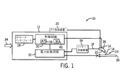
ここで図面に目を向け、先ず図1を参照すると、例示的な溶接システム10が、ワイヤー送給装置14に結合された電源12を含むものとして示されている。図示する実施形態では、電源12はワイヤー送給装置14とは別個であり、そのため、ワイヤー送給装置14は、溶接位置の近くの電源12から幾分かの距離に配置することができる。しかしながら、幾つかの実施態様では、ワイヤー送給装置14は電源12と一体型とすることができることを理解すべきである。電源12は、ワイヤー送給装置14を介してトーチ16に溶接電力を供給することができ、または、電源12は、トーチ16に溶接電力を直接供給することができる。ワイヤー送給装置14は、トーチ16にワイヤ電極18(例えば、ソリッドワイヤ、コアードワイヤ、コーテッドワイヤ)を供給する。電源12と一体に設ける或いは別個に設けることができるガス供給装置20は、トーチ16にガス(例えば、CO2、アルゴン)を供給する。オペレーターは、電極18と加工物26との間にアーク24を点火するようにトーチ16の引金22を引くことができる。幾つかの実施形態では、溶接システム10は、限定されないがプログラマブルロジックコントローラー(PLC)またはロボットコントローラーを含む自動化インターフェースによって作動させることができる。溶接システム10は、溶接ワイヤ(例えば、電極18)、溶接電力およびシールドガスを溶接トーチ16に提供するように設計されている。当業者には理解されるように、溶接トーチ16は、多くの異なるタイプとすることができ、電極18およびガスの様々な組合せの使用を容易にすることができる。
Turning now to the drawings and referring first to FIG. 1, an
溶接システム10は、電源12に設けられたオペレーターインターフェース28を介してオペレーターからデータ設定を受け取ることができる。オペレーターインターフェース28は、電源12の面板に組み込むことができ、溶接プロセス(例えば、スティック、TIG、MIG)、使用するワイヤのタイプ、電圧および電流設定、移行形態(例えば、短絡、パルス、スプレー、パルス)等の設定の選択を可能にすることができる。特に、溶接システム10は、鋼またはアルミニウム等の様々な材料の電極18(例えば、溶接ワイヤ)がトーチ16内に通されるMIG溶接(例えば、パルスMIG、スプレー、短絡、調整金属堆積(Regulated Metal Deposition)(すなわち、RMD(商標))を可能にする。溶接設定は、電源12内の制御回路30に通信される。さらに、または代替的に、制御回路30は、ワイヤー送給装置14、トーチ16、ガス供給装置20、または溶接システム10の別の構成要素内にある。
The
後により詳細に記載する制御回路30は、所望の溶接作業を実行する電力変換回路32によって電極18に印加される溶接電力出力の生成を制御するように動作する。幾つかの実施形態では、制御回路30は、溶接ワイヤから進行中の溶接部の溶融溶接池への溶融金属の短絡移行および/またはスプレー移行の態様を有することができるパルスMIG溶接法を、調整するように適合することができる。後により十分に記載するように、こうした移行形態は、作業中に、電極18と加工物26との間に生じるアーク24に対して電流パルスおよび電圧パルスの動作パラメーターを調整することによって、制御することができる。「パルス溶接」または「パルスMIG溶接」は、進行中の溶融池内への金属溶滴の溶着を制御するように、パルス電力波形が生成される技法を指す。本発明の特定の実施形態では、アークの溶接電流が、溶接電圧に影響を与える異常陰極事象の間に望ましい電流になるように制御される、パルス溶接法を実施することができる。すなわち、異常陰極事象の間の溶接電圧とは無関係に、溶接電流を制御することができる。
The
制御回路30は、トーチ16において電極18に印加される溶接電力(例えば、パルス波形)を供給する電力変換回路32に結合されている。電力変換回路32は、矢印34によって示すように、電力源に結合されている。電力変換回路32に印加される電力は、送配電網において発生することができるが、エンジン駆動発電機、バッテリー、燃料電池または他の代替源によって生成される電力等、他の電力源を使用することもできる。電力変換回路32の構成要素としては、チョッパー、ブーストコンバーター、バックコンバーター、インバーター等を挙げることができる。
The
制御回路30は、トーチ16に供給される溶接電力の電流および/または電圧を制御する。制御回路30は、ワイヤー送給装置14またはトーチ16内の1または複数のセンサー36に少なくとも部分的に基づいて、アーク24の電流および/または電圧を監視することができる。幾つかの実施形態では、制御回路30のプロセッサ38は、センサー36からのフィードバックに少なくとも部分的に基づいて、アーク長または突出し長さを求めおよび/または制御する。アーク長は、本明細書では、電極18と加工物26との間のアークの長さとして定義される。プロセッサ38は、メモリ40に格納されたデータ(例えば、アルゴリズム、命令、動作点)を利用して、アーク長または突出し長さを求めおよび/または制御する。メモリ40に格納されたデータは、オペレーターインターフェース28若しくはネットワーク接続を介して受け取ることができるか、または制御回路30を組み立てる前に予めロードすることができる。電源12の動作は、制御回路30が、溶接作業中に溶接電流を変更する一方で溶接電圧を実質的に一定であるように制御する、定電圧(CV)調整モード等、1または複数のモードで制御することができる。すなわち、溶接電流は、溶接電圧に少なくとも部分的に基づくことができる。さらに、または代替的に、電源12は、溶接電流が溶接電圧とは無関係に制御される電流制御モードで制御することができる。幾つかの実施形態では、電源12は、制御回路30が、溶接作業中に溶接電圧を変更する一方で溶接電流を実質的に一定であるように制御する、定電流(CC)モードで動作するように制御される。
The
図2は、パルス溶接プロセスの溶接電圧50および溶接電流52の波形の実施形態である。パルス周期A、BおよびCにわたる溶接電圧50波形および溶接電流52波形が示されている。各パルス周期のピーク相54の間、制御回路は、電極に供給される溶接電圧50を増大させ、溶融ボールを形成しおよび/または電極の先端から分離して加工物または溶融池に溶着させる。溶接電圧50は、バックグラウンド電圧レベル60から概ねピーク電圧62まで増大し、それにより、溶接電流52をバックグラウンド電流レベル56から概ねピーク電流58まで増大させる。溶接電圧50および溶接電流52は、ピークレベルからバックグラウンド相64まで低減することができる。言い換えれば、溶接電流52は、溶接電圧50に少なくとも部分的に基づいて、ピーク相54の間に間接的に制御される。幾つかの実施形態では、バックグラウンド相64の間、溶融ボールは、溶接電圧50を低減させる短絡事象66において、電極を溶融池に短い時間連結することができる。幾つかの実施形態では、溶融ボールは、短絡事象66なしに電極から溶融池に溶着する。バックグラウンド相64では、制御回路は、概して溶融電圧50をバックグラウンド電圧60で維持することができ、溶接電流52は、電極と加工物との間にアークを維持するように概ねバックグラウンド電流56であり続けることができる。溶接電流52および溶接電圧50を介する溶接電力は、バックグラウンド相64の間、電極の先端に別の溶融ボールを形成し始めることができる。したがって、各パルス周期は、概して、溶接電圧50が増大するピーク相54と、溶接電流52が実質的に定電流値であることが望まれるバックグラウンド相64とによって記述することができる。
FIG. 2 is an embodiment of the waveform of the
本明細書において考察するとき、パルス周期という用語は、パルスMIG溶接法のみに対する溶接電圧50および溶接電流52の波形のサイクル(例えば、ピーク相54、バックグラウンド相64)に限定されるようには意図されていない。理解することができるように、様々なMIG溶接プロセス(例えば、パルスMIG、短絡、スプレーおよびRMD)の溶接電圧50および溶接電流52は周期的である。すなわち、MIGプロセスの各サイクルは、溶接電圧50が上昇した1または複数のピーク相54と溶接電流52が所望であるように実質的に一定である1または複数のバックグラウンド相64とを含む。例えば、ピーク相54は、RMDプロセスのピンチ(pinch)段階、クリア(clear)段階および/またはボール(ball)段階を含むことができ、バックグラウンド相64は、RMDプロセスのブリンク(blink)段階、バックグラウンド(background)段階、短絡前(pre-short)段階および/または湿潤(wet)段階を含むことができる。本明細書で利用するとき、パルス周期という用語は、限定されないが、パルスMIG溶接法、短絡プロセス、スプレープロセス若しくはRMDプロセスまたはそれらの任意の組合せのサイクル(例えば、ピーク相54およびバックグラウンド相64の1または複数のシーケンス)を含むことができる。
As discussed herein, the term pulse period is intended to be limited to the waveform of the
理解することができるように、制御回路30のプロセッサ38は、オペレーターインターフェースを介して入力される所望の溶接パラメーター、すなわち電極、電極の送給速度、ガス、加工物またはそれらの任意の組合せに少なくとも部分的に基づいて、種々の範囲内で溶接電圧50および溶接電流52の値を制御することができる。例えば、バックグラウンド電流レベル56は、約25Aから250Aの間とすることができる。ピーク電流58は、約300Aから700Aの間とすることができる。幾つかの実施形態では、バックグラウンド電圧レベル60は、約15Vから25Vの間とすることができ、ピーク電圧62は約25Vから40Vの間とすることができる。
As can be appreciated, the
パルスプロセスの溶接電圧50および溶接電流52の波形は、概してパルス周期Aに類似することができる。しかしながら、幾つかのパルス周期のバックグラウンド相64において、異常陰極事象68が開始し、様々な時間、持続する可能性がある。幾つかの異常陰極事象68は、バックグラウンド相64の一部の間のみに持続する可能性があり、他の異常陰極事象68は、バックグラウンド相64を通してピーク相54の一部まで持続する可能性がある。異常陰極事象68は、パルス周期BおよびCに示すように、溶接電圧50および溶接電流52に影響を与える可能性がある。パルス周期BおよびCの異常陰極事象68は、後述するような制御回路による制御アルゴリズムが適用されない溶接電圧50および溶接電流52の波形を示す。ピーク相54の後、溶接電圧50は異常陰極事象68において上昇する可能性がある。緩和されない異常陰極事象68は、電極と加工物との間のアークに、アークを制限するかまたは狭めることによって影響を与える。すなわち、パルス周期Bの異常陰極事象68の間のアークは、パルス周期Aのバックグラウンド相64の間の相対的に幅が広いおよび/またはベル状アークと比較して相対的に幅が狭い可能性がある。後述する制御アルゴリズムがない場合、溶接電圧50に基づいて制御される溶接電流52は、制御回路が溶接電圧50を所望のバックグラウンド電圧60で維持しようとしている間に、低電流レベル70まで低減する可能性がある。溶接プロセスに対する緩和されない異常陰極事象68の影響としては、限定されないが、スパッターの発生の増大、一貫しないボール移行、不規則な溶接部外観、アーク安定性の低下、若しくは後続する異常陰極事象68の可能性の増大、またはそれらの任意の組合せを挙げることができる。
The waveforms of the
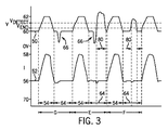
制御回路30のプロセッサ38は、異常陰極事象の発生を確定し、制御アルゴリズムによって溶接電流52を制御して溶接プロセスに対する影響を低減させることができる。図3は、溶接プロセスのパルス周期D、EおよびFにわたるパルスプロセスの溶接電圧50および溶接電流52の波形の一実施形態を示す。パルス周期E、FおよびGは、パルス持続時間が実質的に均一であろう。制御回路は、溶接電圧50を監視して、異常陰極事象80の開始(例えば、溶接電圧50の上昇)を検出する。幾つかの実施形態では、制御回路は、異常陰極事象80の開始について溶接電圧50をバックグラウンド相64の間のみ監視し、および/またはピーク相54の間では監視しない。制御回路30のプロセッサ38は、溶接電圧50を、異常陰極事象80の発生時およびその間に超過する可能性がある検出電圧(例えば、Vdetect)と比較することができる。溶接電圧50が、(例えば、異常陰極事象80の間)検出電圧を概ね超える場合、制御回路30のプロセッサ38は、溶接電圧50に基づいて溶接電流52を制御するのではなく、メモリ40に格納された制御アルゴリズムに少なくとも部分的に基づいて溶接電流52を制御することができる。例えば、制御アルゴリズムは、溶接電圧50のバックグラウンド電圧60からのずれにも関らず異常陰極事象80の間に溶接電流52を概ねバックグラウンド電流56または他の望ましい電流値になるように制御するように、制御回路に対して指示することができる。異常陰極事象80の持続時間としては、限定されないが、バックグラウンド相64の概ね10%、25%、50%若しくは75%未満またはそれより長いバックグラウンド相64の間隔(例えば、部分)を挙げることができる。制御アルゴリズムは、パルス周期EおよびFにおける異常陰極事象80の間に、溶接電流52を、バックグラウンド相64の間にパルス周期Dの間と概ね同じ値になるように制御するように、制御回路30のプロセッサ38に対して指示し、それにより、異常陰極事象80の間に溶接電圧50の上昇によって実質的に影響を受けないように溶接電流52を制御することができる。メモリ40に格納された制御アルゴリズムは、異常陰極事象80の少なくとも一部の間に溶接電圧50とは無関係であるように溶接電流52を制御するように、制御回路30のプロセッサ38に対して指示することができる。幾つかの実施形態では、制御アルゴリズムは、溶接電圧50がバックグラウンド電圧60の近くにない異常陰極事象80の間に、溶接電流52をバックグラウンド電流56で実質的に維持するように、制御回路30のプロセッサ38に対して指示する。
The
異常陰極事象80は、溶接電圧50が概ね最終電圧(例えば、Vend)未満に低下したときに終了する可能性がある。異常陰極事象80がバックグラウンド相64の間に終了する場合、制御アルゴリズムは、バックグラウンド相64の残りの部分に対する電極の動作点に基づいて、溶接電流52をバックグラウンド電流56または別の所定の動的電流値で維持するように、制御回路30のプロセッサ38に対して指示することができる。幾つかの実施形態では、制御アルゴリズムは、異常陰極事象80の前に適所で電圧調整方法(例えば、定電圧)を再開するように、制御回路30のプロセッサ38に対して指示することができる。異常陰極事象80が別の相(例えば、ピーク相54)の間に終了する場合、制御アルゴリズムは、溶接電流52を適切な電流レベルに調整するように制御回路30のプロセッサ38に対して指示することができる。例えば、異常陰極事象80がピーク相54において終了する場合、制御アルゴリズムは、溶接電流52をバックグラウンド電流56とピーク電流レベル58との間の適切な電流レベルになるように制御するように、制御回路30のプロセッサ38に対して指示し、それにより、溶接電流波形52は、パルス周期の間に電流波形の均一性を実質的に維持することができる。例えば、バックグラウンド相64は、各パルス周期に対して同じバックグラウンド時間(例えば、約1ミリ秒から20ミリ秒、2ミリ秒から15ミリ秒、または3ミリ秒から10ミリ秒)を有することができ、ピーク相54は、同じピーク時間(例えば、約0.5ミリ秒から5ミリ秒、0.75ミリ秒から4ミリ秒、または1ミリ秒から3ミリ秒)を有することができる。制御アルゴリズムは、制御回路30のプロセッサ38が、通常の調整モード(例えば、定電圧調整)外にある異常陰極事象80の間に溶接電流52を制御するのを可能にし、それにより、スパッターの発生を低減させ、溶融池へのボール移行の一貫性を向上させ、溶接部の外観を改善し、アーク安定性を向上させ、若しくは後続する異常陰極事象80の可能性を低減させ、またはそれらの任意の組合せをもたらす。
The abnormal cathode event 80 may end when the
検出電圧(Vdetect)および最終電圧(Vend)は、電極特性、溶接作業中に利用されるガス、電極の動作点および/またはシールドガスの動作点に少なくとも部分的に基づくことができる。電極の動作点およびシールドガスの動作点は、実験的に求めて制御回路30のメモリ40に格納することができる。例えば、動作点は、制御アルゴリズムと共にメモリ40に格納することができる。幾つかの実施形態では、VdetectおよびVendは、バックグラウンド電圧60より大きく、ピーク電圧62より小さい可能性がある。例えば、Vdetectは、約25Vから35Vまでの間とすることができ、Vendは、約15Vから25Vまでの間とすることができる。Vdetectに対する電圧値は、約1V、2V、3V,4V、5V、6V、7V、8V、9V若しくは10V、またはバックグラウンド電圧60を超えることができる。さらに、または代替的に、Vdetectは、バックグラウンド電圧60より約1%、2%、3%、5%、10%または20%大きい可能性がある。幾つかの実施形態では、電極およびガスの様々な組合せに対するVdetectおよび/またはVendの値は、溶接プロセスの前にまたはその間に、メモリから制御回路内にロードすることができる。Vdetectおよび/またはVendの値は、電流フィードバック、突出し長さ若しくはアーク長、またはそれらの任意の組合せに少なくとも部分的に基づく模擬電圧とすることができる。非異常陰極パルス周期(例えば、パルス周期D)の間の溶接電圧50は、電極における電圧成分(例えば、VEE)、アークにおける電圧成分(例えば、Varc、Vanode、Vcathode)および加工物における電圧成分を有することができる。幾つかの実施形態では、模擬電圧は、1または複数の非異常陰極パルス周期中の溶接電圧50の別個に計算された電圧成分の合計に少なくとも部分的に基づくことができる。例えば、模擬電圧は、制御回路、電力変換回路およびセンサーのうちの少なくとも1つからリアルタイムフィードバックを受け取る状態観測器(例えば、カルマンフィルター)からのフィードバックに少なくとも部分的に基づくことができる。制御回路30のプロセッサ38は、トーチにおけるセンサーからのフィードバックに少なくとも部分的に基づいて突出し長さおよび/またはアーク長を求めることができる。
The detection voltage (V detect ) and final voltage (V end ) can be based at least in part on electrode characteristics, gas utilized during the welding operation, electrode operating point and / or shielding gas operating point. The operating point of the electrode and the operating point of the shielding gas can be obtained experimentally and stored in the
図4は、溶接システムを動作させ、上述した制御アルゴリズムを開始する方法100の一実施形態を示す。オペレーターは、オペレーターインターフェースを介しておよび/または構成要素(例えば、ワイヤー送給装置、トーチ、ガス供給装置)を電源に結合することにより、溶接作業に対する溶接パラメーターを設定することができる(ブロック102)。溶接パラメーターとしては、限定されないが、電流、電圧、移行形態、パルス持続時間、パルス周波数、加工物材料、電極および供給部、並びにそれらの任意の組合せを挙げることができる。電源がトーチに電力を供給し(ブロック104)、オペレーターは、トーチの電極と加工物との間にアークを点火するように引金を引くことができる(ブロック106)。バックグラウンド相(ブロック108)の間、トーチを介して電極に供給される溶接電力は、ボールを形成し(ブロック110)、電極と加工物との間にアークを維持する。幾つかの実施形態では、制御回路30のプロセッサ38は、バックグラウンド相の間に実質的に一定値であるように溶接電流および溶接電圧を制御することができる。制御回路30のプロセッサ38が、バックグラウンド相が終了した(例えば、バックグラウンド相における時間tがパルス周期のバックグラウンド間隔を超過した)と判断した(ノード112)後、制御回路30は、ピーク相(ブロック114)に遷移することができる。ピーク相(ブロック114)の間、溶融ボールが、溶融池に溶着するために電極から分離することができる(ブロック116)。制御回路30は、ピーク相の間に増大するように溶接電流および溶接電圧を制御することができる。バックグラウンド相(ブロック108)およびピーク相(ブロック114)は、オペレーターが引金を引く(ブロック106)かまたは自動化インターフェースが溶接システムに関与している間、溶接プロセスの持続時間にわたって繰り返すことができる。幾つかの実施形態では、制御回路30のプロセッサ38は、繰り返されるバックグラウンド相とピーク相との間に追加の相を置いて、溶接電流および溶接電圧を制御することができる。
FIG. 4 illustrates one embodiment of a
バックグラウンド相(ブロック108)の間、制御回路30のプロセッサ38は、溶接電圧を監視する。ノード118において、制御回路30のプロセッサ38は、溶接電圧を溶接検出値(Vdetect)と比較して、異常陰極事象が発生しているか否かを判断する。Vdetectは、動的に求めおよび/または制御回路のメモリからロードすることができる。溶接電圧が電圧検出値を超える場合、制御回路30のプロセッサ38は、制御アルゴリズム120を利用して、溶接プロセスに対する異常陰極事象の影響を緩和する。制御アルゴリズム120では、制御回路30のプロセッサ38は、アクティブな電圧調整方法を停止する(ブロック122)かまたは一時停止する。例えば、制御回路30のプロセッサ38は、電圧調整方法(例えば、定電圧方法)を利用して、所望のアーク長または突出し長さを維持するように溶接電圧および/または溶接電流を制御することができる。幾つかの実施形態では、制御回路30のプロセッサ38は、メモリ40から格納されたデータ(例えば、移動平均、センサーフィードバック)を消去すること等によって、アクティブな電圧調整方法をリセットすることができる(ブロック124)。アクティブな電圧調整方法をリセットすることにより、電圧調整方法の精度および/または信頼性を向上させることができ、それにより、アークの安定性が向上する。例えば、アクティブな電圧調整方法は、メモリ40に格納された、事前に測定された電流測定値および/または電圧測定値を利用することができる。異常陰極事象の間のアークの状態(例えば、測定された電流および/または電圧)は、非異常陰極事象(例えば、パルス周期D)のバックグラウンド相の間とは異なる。したがって、アクティブな電圧調整方法で利用されるメモリ40に格納された、事前に測定された電流測定値および/または電圧測定値がリセットされ(ブロック124)、アクティブな電圧調整方法は、アクティブな電圧調整方法に対して異常陰極事象からの測定された電流測定値および/または電圧測定値を利用することなく、ブロック132において再開することができる。
During the background phase (block 108), the
制御アルゴリズム120は、溶接電流を所望のバックグラウンド電流、所定の電流値、または動的に求められる電流値に調整する(ブロック126)ように制御回路30のプロセッサ38に対して指示する。幾つかの実施形態では、所望のバックグラウンド電流は、先行するパルス周期からの以前のバックグラウンド相の間のバックグラウンド電流と概ね同じであろう。制御回路30のプロセッサ38は、電極、ワイヤまたはそれらの任意の組合せに少なくとも部分的に基づいて、溶接電流を所望のバックグラウンド電流までランプ速度(例えば、線形)で増大または低減させることができる。ランプ速度は、メモリ40に格納するか、または他の方法でバックグラウンド相の間に制御回路30内で求めることができる。さらに、または代替的に、ランプ速度は、実験的に求めてアルゴリズムと共にメモリ40に格納することができる。
The
制御回路30のプロセッサ38が、バックグラウンド相が終了していない(例えば、バックグラウンド相における時間tがバックグラウンド間隔を超過していない)と判断した場合(ノード128)、制御回路30のプロセッサ38は、溶接電圧が最終電圧Vend未満であるか否かを判断する(ノード130)。溶接電圧がVend未満である場合、制御アルゴリズムは、異常陰極事象が終了したと判断することができ、制御アルゴリズムは、アクティブな電圧調整方法を再開し(ブロック132)ブロック110に戻るように、制御回路30のプロセッサ38に対して指示する。溶接電圧がVendを超える場合、制御アルゴリズムは、溶接電流をバックグラウンド電流に調整し(ブロック126)、バックグラウンド相が終了するかまたは溶接電圧がVend未満となる(例えば、異常陰極事象が終了する)まで、ノード128および130を循環することができる。溶接電圧がVendを超えている間にバックグラウンド相が終了した場合、制御アルゴリズムは、次の相(例えば、ピーク相114)に対して溶接電流を調整し(ブロック134)、アクティブな電圧調整方法を再開する(ブロック136)ように、制御回路に対して指示する。例えば、異常陰極事象がピーク相114まで持続する場合、制御アルゴリズムは、以前のピーク溶接電流波形に実質的に対応するように溶接電流を適切な溶接電流まで増大させるように、制御回路30のプロセッサ38に対して指示し、それにより、溶接電流のピーク相に対する異常陰極事象の影響を低減させる。
If the
本明細書において、本発明の幾つかの特徴だけが図示および説明されてきたが、当業者には多くの変更および変形が思い浮かぶであろう。それゆえ、添付の特許請求の範囲は、本発明の真の趣旨に入るような全ての変更および変形を包含することを意図していることを理解されたい。 While only certain features of the invention have been illustrated and described herein, many modifications and changes will occur to those skilled in the art. Therefore, it is to be understood that the appended claims are intended to cover all such changes and modifications as fall within the true spirit of the invention.
10 溶接システム
12 電源
14 ワイヤー送給装置
16 溶接トーチ
18 ワイヤ電極
20 ガス供給装置
22 引金
24 アーク
26 加工物
28 オペレーターインターフェース
30 制御回路
32 電力変換回路
34 矢印
36 センサー
38 プロセッサ
40 メモリ
50 溶融電圧
50 溶接電圧
52 溶接電流
54 ピーク相
56 バックグラウンド電流
58 ピーク電流
60 バックグラウンド電圧
62 ピーク電圧
64 バックグラウンド相
66 短絡事象
68 異常陰極事象
70 低電流レベル
80 異常陰極事象
114 ピーク相
118 ノード
120 制御アルゴリズム
128 ノード
132 ブロック
DESCRIPTION OF
Claims (20)
前記電源に結合された制御回路であって、前記バックグラウンド相において前記溶接電圧の電圧値が検出電圧を超える場合に、前記溶接電流をバックグラウンド電流になるように制御する制御回路とを具備する溶接システム。 A power supply for supplying a welding power consisting of a welding current and a welding voltage to the torch in a plurality of pulse periods each including a peak phase and a background phase;
A control circuit coupled to the power supply, wherein the control circuit controls the welding current to become a background current when a voltage value of the welding voltage exceeds a detection voltage in the background phase. Welding system.
前記溶接電圧をバックグラウンド電圧に制御し、かつ前記溶接電流を前記溶接電圧に少なくとも部分的に基づいて制御する定電圧モードと、
前記溶接電圧とは無関係に前記溶接電流を制御する電流制御モードであって、前記制御回路は、前記バックグラウンド相において前記電圧値が前記検出電圧を超える場合に、前記電源の動作を該電流制御モードに変更するように構成され、前記制御回路は、前記ピーク相において前記電源の動作を前記定電圧モードに変更するように構成されている、電流制御モードとを含む請求項1に記載の溶接システム。 The power source is configured to operate in a plurality of control modes during the background phase, the plurality of control modes being:
A constant voltage mode for controlling the welding voltage to a background voltage and controlling the welding current based at least in part on the welding voltage;
A current control mode for controlling the welding current independently of the welding voltage, wherein the control circuit controls the operation of the power supply when the voltage value exceeds the detection voltage in the background phase. The welding according to claim 1, further comprising: a current control mode configured to change to a mode, wherein the control circuit is configured to change the operation of the power source to the constant voltage mode in the peak phase. system.
各パルス周期がバックグラウンド相とピーク相とを含む複数のパルス周期を通して溶接電流および溶接電圧を電極に供給し、
前記複数のパルス周期の第1のパルス周期の前記バックグラウンド相の間、前記溶接電圧の電圧値が検出電圧を超えたときに少なくとも部分的に基づいて異常陰極事象の発生を検出し、
前記異常陰極事象の一部の間に前記溶接電流を望ましい電流になるように制御することを含み、
異常陰極事象の前記一部は、前記第1のパルス周期の前記バックグラウンド相の間隔を含み、前記溶接電流は、前記異常陰極事象の前記一部の間の前記溶接電圧とは無関係に制御されるようにした溶接システムの操作方法。 A method of operating a welding system, comprising:
Supplying welding current and welding voltage to the electrodes through multiple pulse periods, each pulse period including background phase and peak phase,
Detecting an occurrence of an abnormal cathode event based at least in part when a voltage value of the welding voltage exceeds a detection voltage during the background phase of the first pulse period of the plurality of pulse periods;
Controlling the welding current to be a desired current during a portion of the abnormal cathode event;
The portion of the abnormal cathode event includes an interval of the background phase of the first pulse period, and the welding current is controlled independently of the welding voltage during the portion of the abnormal cathode event. To operate the welding system.
前記検知された電流値、前記検知された電圧値またはそれらの任意の組合せに少なくとも部分的に基づいて、前記検出電圧を求めることと、
を含む請求項7に記載の方法。 Detecting the current value of the welding current and the voltage value of the welding voltage;
Determining the detected voltage based at least in part on the sensed current value, the sensed voltage value, or any combination thereof;
The method of claim 7 comprising:
前記第1のパルス周期の前記バックグラウンド相における前記異常陰極事象の検出時に、前記定電圧調整方法を一時停止することと、
前記溶接電圧の前記電圧値が、前記第1のパルス周期の前記バックグラウンド相の間の最終電圧未満である場合、前記第1パルス周期の前記バックグラウンド相に続くピーク相が開始した場合、またはそれらの任意の組合せの場合に、前記定電圧調整方法を再開することと、
を含む請求項7に記載の方法。 Controlling the welding current during each pulse period of the plurality of pulse periods based at least in part on a constant voltage adjustment method;
Suspending the constant voltage adjustment method upon detection of the abnormal cathode event in the background phase of the first pulse period;
When the voltage value of the welding voltage is less than the final voltage during the background phase of the first pulse period, when the peak phase following the background phase of the first pulse period starts, or In the case of any combination thereof, restarting the constant voltage adjustment method;
The method of claim 7 comprising:
前記第1のパルス周期のバックグラウンド相の第1の部分では、バックグラウンド電流値の溶接電流およびバックグラウンド電圧値の溶接電圧を前記溶接ワイヤに供給し、
前記第1のパルス周期の前記バックグラウンド相において異常陰極事象を含む第2の部分では、溶接電圧とは無関係に溶接電流を前記バックグラウンド電流値になるように制御することを含む方法。 During the first peak phase of the first pulse period, the welding current is indirectly controlled based at least in part on the welding voltage during the first peak phase, so that the welding current and the peak voltage at the peak current value are controlled. Supply the welding voltage of the value to the welding wire,
In a first part of the background phase of the first pulse period, a welding current having a background current value and a welding voltage having a background voltage value are supplied to the welding wire;
Controlling a welding current to be the background current value independent of a welding voltage in a second portion including an abnormal cathode event in the background phase of the first pulse period.
Applications Claiming Priority (5)
| Application Number | Priority Date | Filing Date | Title |
|---|---|---|---|
| US201361834738P | 2013-06-13 | 2013-06-13 | |
| US61/834,738 | 2013-06-13 | ||
| US14/291,972 | 2014-05-30 | ||
| US14/291,972 US11045891B2 (en) | 2013-06-13 | 2014-05-30 | Systems and methods for anomalous cathode event control |
| PCT/US2014/041201 WO2014200825A1 (en) | 2013-06-13 | 2014-06-06 | System and methods for anomalous cathode event control with control of welding current according to the state detected voltage |
Publications (2)
| Publication Number | Publication Date |
|---|---|
| JP2016521641A true JP2016521641A (en) | 2016-07-25 |
| JP2016521641A5 JP2016521641A5 (en) | 2017-07-20 |
Family
ID=52018336
Family Applications (1)
| Application Number | Title | Priority Date | Filing Date |
|---|---|---|---|
| JP2016519554A Pending JP2016521641A (en) | 2013-06-13 | 2014-06-06 | System and method for abnormal cathode event control to control welding current according to status detection voltage |
Country Status (10)
| Country | Link |
|---|---|
| US (1) | US11045891B2 (en) |
| EP (1) | EP3007849B1 (en) |
| JP (1) | JP2016521641A (en) |
| KR (1) | KR102174279B1 (en) |
| CN (1) | CN105307808B (en) |
| AU (1) | AU2014278502B2 (en) |
| BR (1) | BR112015031305A2 (en) |
| CA (1) | CA2912182C (en) |
| MX (1) | MX348871B (en) |
| WO (1) | WO2014200825A1 (en) |
Families Citing this family (29)
| Publication number | Priority date | Publication date | Assignee | Title |
|---|---|---|---|---|
| US10040143B2 (en) | 2012-12-12 | 2018-08-07 | Illinois Tool Works Inc. | Dabbing pulsed welding system and method |
| US10906114B2 (en) | 2012-12-21 | 2021-02-02 | Illinois Tool Works Inc. | System for arc welding with enhanced metal deposition |
| US9950383B2 (en) | 2013-02-05 | 2018-04-24 | Illinois Tool Works Inc. | Welding wire preheating system and method |
| US10828728B2 (en) | 2013-09-26 | 2020-11-10 | Illinois Tool Works Inc. | Hotwire deposition material processing system and method |
| US11154946B2 (en) | 2014-06-30 | 2021-10-26 | Illinois Tool Works Inc. | Systems and methods for the control of welding parameters |
| US11198189B2 (en) | 2014-09-17 | 2021-12-14 | Illinois Tool Works Inc. | Electrode negative pulse welding system and method |
| US11478870B2 (en) | 2014-11-26 | 2022-10-25 | Illinois Tool Works Inc. | Dabbing pulsed welding system and method |
| US10189106B2 (en) | 2014-12-11 | 2019-01-29 | Illinois Tool Works Inc. | Reduced energy welding system and method |
| US11370050B2 (en) | 2015-03-31 | 2022-06-28 | Illinois Tool Works Inc. | Controlled short circuit welding system and method |
| US11285559B2 (en) | 2015-11-30 | 2022-03-29 | Illinois Tool Works Inc. | Welding system and method for shielded welding wires |
| US10610946B2 (en) | 2015-12-07 | 2020-04-07 | Illinois Tool Works, Inc. | Systems and methods for automated root pass welding |
| US10675699B2 (en) | 2015-12-10 | 2020-06-09 | Illinois Tool Works Inc. | Systems, methods, and apparatus to preheat welding wire |
| US10695856B2 (en) * | 2016-10-07 | 2020-06-30 | Illinois Tool Works Inc. | System and method for short arc welding |
| US10766092B2 (en) | 2017-04-18 | 2020-09-08 | Illinois Tool Works Inc. | Systems, methods, and apparatus to provide preheat voltage feedback loss protection |
| US10870164B2 (en) | 2017-05-16 | 2020-12-22 | Illinois Tool Works Inc. | Systems, methods, and apparatus to preheat welding wire |
| CA3066666A1 (en) | 2017-06-09 | 2018-12-13 | Illinois Tool Works Inc. | Contact tips with screw threads and head to enable unthreading of the screw threads comprising longitudinal slots for gas flow; welding torch with contact tips |
| EP3634684B1 (en) | 2017-06-09 | 2022-10-05 | Illinois Tool Works Inc. | Welding torch with a first contact tip to preheat welding wire and a second contact tip |
| US11524354B2 (en) | 2017-06-09 | 2022-12-13 | Illinois Tool Works Inc. | Systems, methods, and apparatus to control weld current in a preheating system |
| US11590597B2 (en) | 2017-06-09 | 2023-02-28 | Illinois Tool Works Inc. | Systems, methods, and apparatus to preheat welding wire |
| WO2018227196A1 (en) | 2017-06-09 | 2018-12-13 | Illinois Tool Works Inc. | Welding torch, with two contact tips and a plurality of liquid cooling assemblies for conducting currents to the contact tips |
| US11020813B2 (en) | 2017-09-13 | 2021-06-01 | Illinois Tool Works Inc. | Systems, methods, and apparatus to reduce cast in a welding wire |
| US11897059B2 (en) * | 2018-02-26 | 2024-02-13 | Illinois Tool Works Inc. | Current limiting secondary contact |
| JP7026576B2 (en) * | 2018-05-28 | 2022-02-28 | 株式会社神戸製鋼所 | Welding condition determination device, welding condition determination method, and program |
| US11654503B2 (en) | 2018-08-31 | 2023-05-23 | Illinois Tool Works Inc. | Submerged arc welding systems and submerged arc welding torches to resistively preheat electrode wire |
| US11014185B2 (en) | 2018-09-27 | 2021-05-25 | Illinois Tool Works Inc. | Systems, methods, and apparatus for control of wire preheating in welding-type systems |
| US11958142B2 (en) | 2018-10-19 | 2024-04-16 | Illinois Tool Works Inc. | Systems and methods to control pulse welding |
| US20200122260A1 (en) * | 2018-10-22 | 2020-04-23 | Illinois Tool Works Inc. | Systems and methods for controlling arc initiation and termination in a welding process |
| WO2020132251A2 (en) | 2018-12-19 | 2020-06-25 | Illinois Tool Works Inc. | Systems, methods and apparatus to preheat welding wire |
| US11772182B2 (en) | 2019-12-20 | 2023-10-03 | Illinois Tool Works Inc. | Systems and methods for gas control during welding wire pretreatments |
Citations (2)
| Publication number | Priority date | Publication date | Assignee | Title |
|---|---|---|---|---|
| JPS5719166A (en) * | 1980-07-08 | 1982-02-01 | Mitsubishi Electric Corp | Pulse arc welding device |
| JP2006205189A (en) * | 2005-01-26 | 2006-08-10 | Matsushita Electric Ind Co Ltd | Arc blow countermeasures control method, and consumable electrode type pulse arc welding equipment |
Family Cites Families (192)
| Publication number | Priority date | Publication date | Assignee | Title |
|---|---|---|---|---|
| US2416047A (en) | 1943-07-10 | 1947-02-18 | George A Dolan | Combined reactor and induction preheater for use in electrode arc welding |
| US2365958A (en) | 1943-07-10 | 1944-12-26 | Electric Arc Inc | Continuous arc welding system |
| GB1103882A (en) | 1964-03-14 | 1968-02-21 | Yawata Iron & Steel Co | High speed arc welding method |
| FR1443701A (en) | 1965-08-06 | 1966-06-24 | British Oxygen Co Ltd | Electric Arc Welding Improvements |
| US4188419A (en) | 1971-02-12 | 1980-02-12 | Licentia Patent-Verwaltungs-G.M.B.H. | Method for preventing cracks below seams during plating and welding |
| US3946349A (en) | 1971-05-03 | 1976-03-23 | The United States Of America As Represented By The Secretary Of The Air Force | High-power, low-loss high-frequency electrical coil |
| US3725629A (en) | 1971-07-16 | 1973-04-03 | Park O Ind Inc | Slab heating device |
| US3809853A (en) | 1972-08-24 | 1974-05-07 | Union Carbide Corp | Method for short circuit metal transfer arc welding |
| US3849871A (en) | 1973-08-06 | 1974-11-26 | Neander H | Method for welding pipes |
| DE2501928A1 (en) | 1975-01-18 | 1976-07-22 | Maschf Augsburg Nuernberg Ag | Preventing high short circuit currents when striking an arc - for the metal inert-gas welding of aluminium |
| GB1580443A (en) | 1976-08-21 | 1980-12-03 | Lucas Industries Ltd | Electrical coil assembly |
| ZA793101B (en) | 1978-07-05 | 1980-04-30 | Lucas Industries Ltd | Electrical coil assembly |
| SU872102A1 (en) | 1979-11-20 | 1981-10-15 | Уфимский авиационный институт им.С.Орджоникидзе | Arc-length stabilization method |
| DE3021659C2 (en) | 1980-06-10 | 1985-01-17 | M.A.N. Maschinenfabrik Augsburg-Nürnberg AG, 4200 Oberhausen | Process for measuring and controlling the feed rate of automatic welding machines |
| JPS57109573A (en) | 1980-12-27 | 1982-07-08 | Mitsubishi Electric Corp | Pulse arc welding method |
| US4447703A (en) | 1981-11-13 | 1984-05-08 | Westinghouse Electric Corp. | Method and apparatus for arc welding |
| JPS58107274U (en) | 1982-01-08 | 1983-07-21 | 三菱電機株式会社 | Hot wire type arc welding torch |
| US4536634A (en) | 1982-01-08 | 1985-08-20 | Mitsubishi Denki Kabushiki Kaisha | Hot wire arc welding torch assembly |
| US4531040A (en) | 1982-01-11 | 1985-07-23 | Mitsubishi Denki K.K. | Hot wire type arc welding torch and cable |
| US4546234A (en) | 1983-08-11 | 1985-10-08 | Kabushiki Kaisha Kobe Seiko Sho | Output control of short circuit welding power source |
| JPH0679781B2 (en) | 1984-07-02 | 1994-10-12 | バブコツク日立株式会社 | Hot wire TIG welding equipment |
| JPS60108176A (en) | 1983-11-18 | 1985-06-13 | Osaka Denki Kk | Arc starting method in consumable electrode type arc welding method |
| JPS60108175A (en) | 1983-11-18 | 1985-06-13 | Osaka Denki Kk | Arc starting method in consumable electrode type arc welding method |
| CN86101294B (en) | 1985-02-13 | 1988-11-23 | 巴布考克日立株式会社 | Tungsten arc semiautomatic welding apparatus with inert atmosphere |
| US4631385A (en) | 1985-03-29 | 1986-12-23 | Dimetrics, Inc. | Automated position detectors and welding system utilizing same |
| US4604510A (en) | 1985-05-20 | 1986-08-05 | Tocco, Inc. | Method and apparatus for heat treating camshafts |
| US4580026A (en) | 1985-06-05 | 1986-04-01 | Westinghouse Electric Corp. | Method and apparatus for controlling the temperature of continuously fed wires |
| US4667083A (en) | 1986-02-14 | 1987-05-19 | Westinghouse Electric Corp. | Torch for preheating a continuously fed welding wire |
| US4954691A (en) | 1986-12-10 | 1990-09-04 | The Lincoln Electric Company | Method and device for controlling a short circuiting type welding system |
| US5001326A (en) | 1986-12-11 | 1991-03-19 | The Lincoln Electric Company | Apparatus and method of controlling a welding cycle |
| US4897523A (en) | 1986-12-11 | 1990-01-30 | The Lincoln Electric Company | Apparatus and method of short circuiting arc welding |
| US5148001A (en) | 1986-12-11 | 1992-09-15 | The Lincoln Electric Company | System and method of short circuiting arc welding |
| JPS6471575A (en) | 1987-09-10 | 1989-03-16 | Matsushita Electric Ind Co Ltd | Method for restraining and controlling over welding current |
| JPH07115183B2 (en) | 1988-06-29 | 1995-12-13 | 三菱電機株式会社 | Load voltage detection system, pulse arc welding apparatus, pulse laser apparatus and surface treatment apparatus using the detection system |
| US4950348A (en) | 1988-10-13 | 1990-08-21 | Elva Induksjon A/S | Method for joining structural elements by heating of a binder |
| GB8900738D0 (en) | 1989-01-13 | 1989-03-08 | Central Electr Generat Board | Welding method and apparatus |
| SE8900758A0 (en) | 1989-03-06 | 1990-09-07 | Esab Ab | Turn on the pulse arc welding |
| US4973821A (en) | 1989-04-03 | 1990-11-27 | Donald L. Martin | Control unit for welding apparatus having offset and tracking control features |
| US5118028A (en) | 1989-08-29 | 1992-06-02 | Sumitomo Metal Industries, Ltd. | Diffusion bonding method for corrosion-resistant materials |
| JP2935434B2 (en) | 1990-03-30 | 1999-08-16 | 日立ビアメカニクス株式会社 | Method and apparatus for controlling TIG welding power supply |
| US5140123A (en) | 1990-05-25 | 1992-08-18 | Kusakabe Electric & Machinery Co., Ltd. | Continuous manufacturing method for a metal welded tube and a manufacturing apparatus therefor |
| FR2663490B1 (en) | 1990-06-15 | 1992-09-11 | Rotelec Sa | INDUCTIVE HEATING COIL. |
| US5101086A (en) | 1990-10-25 | 1992-03-31 | Hydro-Quebec | Electromagnetic inductor with ferrite core for heating electrically conducting material |
| US5352871A (en) | 1991-02-20 | 1994-10-04 | Metcal Inc | System and method for joining plastic materials |
| US5270516A (en) | 1991-04-01 | 1993-12-14 | Matsushita Electric Industrial Co., Ltd. | Arc welding machine |
| DE4121237C2 (en) | 1991-06-27 | 1994-07-21 | Utp Schweissmaterial | Electronic welding current generator for pulsed arc welding |
| US5343023A (en) | 1991-08-23 | 1994-08-30 | Miller Electric Mfg. Co. | Induction heater having a power inverter and a variable frequency output inverter |
| DE4141927C2 (en) | 1991-12-19 | 1995-06-14 | Mtu Maintenance Gmbh | Method and device for welding workpieces |
| US5315089A (en) | 1992-03-02 | 1994-05-24 | Westinghouse Electric Corporation | System and method for converting an AGTAW welder into an AGMAW welder |
| US5412184A (en) | 1992-04-16 | 1995-05-02 | Gas Research Institute | Industion heating tool |
| US5349156A (en) | 1992-06-01 | 1994-09-20 | The United States Of America As Represented By The Secretary Of Commerce | Sensing of gas metal arc welding process characteristics for welding process control |
| US5278390A (en) | 1993-03-18 | 1994-01-11 | The Lincoln Electric Company | System and method for controlling a welding process for an arc welder |
| JP3209821B2 (en) | 1993-03-31 | 2001-09-17 | 日立ビアメカニクス株式会社 | Power control method of consumable electrode type gas shielded arc welding and welding device therefor |
| US5367138A (en) | 1993-06-28 | 1994-11-22 | Automation International Incorporated | Welding assurance control techniques |
| US5466916A (en) | 1993-09-24 | 1995-11-14 | Hidec Co., Ltd. | Method and apparatus for joint resin pipes using high-frequency electric induction heating |
| CN2181354Y (en) | 1993-11-17 | 1994-11-02 | 牟青岳 | Network voltage compensator for electric welder |
| JP3221203B2 (en) | 1994-01-13 | 2001-10-22 | 株式会社ダイヘン | Consumable electrode arc welding control method and power supply device |
| US5461215A (en) | 1994-03-17 | 1995-10-24 | Massachusetts Institute Of Technology | Fluid cooled litz coil inductive heater and connector therefor |
| EP0688626B1 (en) | 1994-05-27 | 2000-02-16 | Kabushiki Kaisha Toshiba | Control equipment for resistance welding machine |
| US5710413A (en) | 1995-03-29 | 1998-01-20 | Minnesota Mining And Manufacturing Company | H-field electromagnetic heating system for fusion bonding |
| US5708253A (en) | 1995-06-07 | 1998-01-13 | Hill Technical Services, Inc. | Apparatus and method for computerized interactive control, measurement and documentation of arc welding |
| US5714738A (en) | 1995-07-10 | 1998-02-03 | Watlow Electric Manufacturing Co. | Apparatus and methods of making and using heater apparatus for heating an object having two-dimensional or three-dimensional curvature |
| US5783799A (en) | 1996-01-11 | 1998-07-21 | Illinois Tool Works Inc. | Series resonant converter, and method and apparatus for control thereof |
| US5773799A (en) | 1996-04-01 | 1998-06-30 | Gas Research Institute | High-frequency induction heating power supply |
| BR9701473A (en) | 1996-04-22 | 1998-09-08 | Illinois Tool Works | System and method for inductive heating of a workpiece and system for continuous segmented inductive heating of a workpiece |
| US5742029A (en) | 1996-07-15 | 1998-04-21 | The Lincoln Electric Company | Method of welding wallpaper alloy an arc welder modified to practice same |
| US5739506A (en) | 1996-08-20 | 1998-04-14 | Ajax Magnethermic Corporation | Coil position adjustment system in induction heating assembly for metal strip |
| US5968587A (en) | 1996-11-13 | 1999-10-19 | Applied Materials, Inc. | Systems and methods for controlling the temperature of a vapor deposition apparatus |
| US5756967A (en) | 1997-04-09 | 1998-05-26 | The United States Of America As Represented By The Secretary Of Commerce | Sensing ARC welding process characteristics for welding process control |
| US5963022A (en) | 1997-06-05 | 1999-10-05 | Square D Company | Method and apparatus for compensating phase distortion caused by a high impedance voltage source |
| JPH11156542A (en) | 1997-11-28 | 1999-06-15 | Daihen Corp | Cable voltage lowering compensation method for stud welding |
| US6051810A (en) * | 1998-01-09 | 2000-04-18 | Lincoln Global, Inc. | Short circuit welder |
| US6087626A (en) | 1998-02-17 | 2000-07-11 | Illinois Tool Works Inc. | Method and apparatus for welding |
| US6090067A (en) | 1998-02-19 | 2000-07-18 | Carter; Bruce C. | Surface access hemostatic valve |
| DE19808383A1 (en) | 1998-02-27 | 1999-09-02 | Volkswagen Ag | Method for MIG/MAG electric arc welding to join two or more components made of light metals or alloys |
| US6008470A (en) | 1998-03-26 | 1999-12-28 | University Of Kentucky Research Foundation | Method and system for gas metal arc welding |
| US6002104A (en) | 1998-04-17 | 1999-12-14 | Lincoln Global, Inc. | Electric arc welder and controller therefor |
| US6115273A (en) | 1998-07-09 | 2000-09-05 | Illinois Tool Works Inc. | Power converter with low loss switching |
| US6292715B1 (en) | 1998-10-27 | 2001-09-18 | Perry Investments, Inc. | Robotic process planning method and apparatus using templates |
| US6906284B2 (en) | 1998-12-24 | 2005-06-14 | You-Chul Kim | Arc welding method |
| US6204476B1 (en) | 1999-05-12 | 2001-03-20 | Illinois Tool Works | Welding power supply for pulsed spray welding |
| AT409833B (en) | 1999-06-04 | 2002-11-25 | Fronius Schweissmasch Prod | METHOD FOR DETERMINING THE WELDING PROCESS VOLTAGE |
| US6169263B1 (en) | 1999-08-02 | 2001-01-02 | Automation International Inc. | Techniques for adaptive control of force in resistance welding applications |
| AT409601B (en) | 1999-11-02 | 2002-09-25 | Fronius Schweissmasch Prod | METHOD FOR TRANSMITTING DATA AND / OR SYNCHRONIZING BETWEEN AT LEAST TWO WELDING DEVICES AND THE DEVICE THEREFOR |
| US6560513B2 (en) | 1999-11-19 | 2003-05-06 | Fanuc Robotics North America | Robotic system with teach pendant |
| US6331694B1 (en) | 1999-12-08 | 2001-12-18 | Lincoln Global, Inc. | Fuel cell operated welder |
| AT412388B (en) | 2000-01-20 | 2005-02-25 | Fronius Schweissmasch Prod | METHOD FOR REGULATING A WELDING CURRENT SOURCE WITH A RESONANCE CIRCUIT |
| AUPQ528400A0 (en) | 2000-01-27 | 2000-02-17 | Crc For Welded Structures Limited | A welding control system |
| US6265688B1 (en) | 2000-02-03 | 2001-07-24 | Norman A. Lyshkow | Method of welding metals and apparatus for use therefor |
| US6278074B1 (en) | 2000-02-28 | 2001-08-21 | Lincoln Global, Inc. | Method and system for welding railroad rails |
| US6248976B1 (en) | 2000-03-14 | 2001-06-19 | Lincoln Global, Inc. | Method of controlling arc welding processes and welder using same |
| JP2001276971A (en) | 2000-03-29 | 2001-10-09 | Hitachi Ltd | Controlling method and apparatus for high frequency pulse welding machine |
| AU2001275097A1 (en) | 2000-06-02 | 2001-12-17 | Richard L. Thelen | Gap welding process |
| US6479792B1 (en) | 2000-09-06 | 2002-11-12 | Illinois Tool Works Inc. | Welding machine, system and method therefor |
| AU2002224012A1 (en) | 2000-11-23 | 2002-06-03 | The Indian Institute Of Technology (Iitd) | Analog to digital converter |
| EP1340576A4 (en) | 2000-12-07 | 2007-12-05 | Honda Motor Co Ltd | Control method of arc welding and arc welder |
| US6583386B1 (en) | 2000-12-14 | 2003-06-24 | Impact Engineering, Inc. | Method and system for weld monitoring and tracking |
| US6501049B2 (en) | 2001-01-23 | 2002-12-31 | Lincoln Global, Inc. | Short circuit arc welder and method of controlling same |
| US6486439B1 (en) | 2001-01-25 | 2002-11-26 | Lincoln Global, Inc. | System and method providing automated welding information exchange and replacement part order generation |
| US6624388B1 (en) | 2001-01-25 | 2003-09-23 | The Lincoln Electric Company | System and method providing distributed welding architecture |
| US6847956B2 (en) | 2001-02-06 | 2005-01-25 | General Electric Company | System and method for determining specific requirements from general requirements documents |
| US6359258B1 (en) | 2001-02-16 | 2002-03-19 | Lincoln Global, Inc. | Method of determining cable impedance |
| CA2345836A1 (en) | 2001-02-23 | 2002-08-27 | Tony Lee Arndt | Method and system for hot wire welding |
| US6515258B2 (en) | 2001-02-28 | 2003-02-04 | General Electric Company | Long reach welding torch and method for selecting torch shape |
| US6472634B1 (en) | 2001-04-17 | 2002-10-29 | Lincoln Global, Inc. | Electric arc welding system |
| US6515259B1 (en) | 2001-05-29 | 2003-02-04 | Lincoln Global, Inc. | Electric arc welder using high frequency pulses |
| DE10136992A1 (en) | 2001-07-23 | 2003-02-06 | Emhart Llc Newark | Short duration arc welding involves comparing unsmoothed measurement curve with tolerance curve generated from smoothed measurement curve to detect high frequency faults |
| US6642482B2 (en) | 2001-09-19 | 2003-11-04 | Illinois Tool Works Inc. | Welding-type system with robot calibration |
| US6747247B2 (en) | 2001-09-19 | 2004-06-08 | Illinois Tool Works Inc. | Welding-type power supply with a state-based controller |
| US6670579B2 (en) | 2001-09-19 | 2003-12-30 | Illinois Tool Works Inc. | Welding-type system with network and multiple level messaging between components |
| JP4263886B2 (en) | 2002-02-22 | 2009-05-13 | 株式会社ダイヘン | Arc length control method for pulse arc welding |
| US6969823B2 (en) | 2002-07-23 | 2005-11-29 | Illinois Tool Works Inc. | Method and apparatus for controlling a welding system |
| US6984806B2 (en) | 2002-07-23 | 2006-01-10 | Illinois Tool Works Inc. | Method and apparatus for retracting and advancing a welding wire |
| US6720529B2 (en) | 2002-09-05 | 2004-04-13 | Illinois Tool Works Inc. | Autothread control for a wire feeder of a welding system |
| JP4478378B2 (en) | 2002-09-26 | 2010-06-09 | 株式会社ダイヘン | Output control method for welding power supply |
| US6909067B2 (en) | 2002-10-09 | 2005-06-21 | Illinois Tool Works Inc. | Method and apparatus for welding with CV control |
| US6707001B1 (en) | 2002-10-11 | 2004-03-16 | Illinois Tool Works Inc. | Method and apparatus of voltage protection for a welding-type device |
| US6812504B2 (en) | 2003-02-10 | 2004-11-02 | Micron Technology, Inc. | TFT-based random access memory cells comprising thyristors |
| US6974932B2 (en) | 2003-03-31 | 2005-12-13 | Illinois Tool Works Inc. | Method and apparatus for welding |
| US6995338B2 (en) | 2003-03-31 | 2006-02-07 | Illinois Tool Works Inc. | Method and apparatus for short circuit welding |
| US6974931B2 (en) | 2003-05-07 | 2005-12-13 | Illinois Tool Works Inc. | Method and apparatus for pulse and short circuit arc welding |
| US6933466B2 (en) | 2003-05-08 | 2005-08-23 | Illinois Tool Works Inc. | Method and apparatus for arc welding with wire heat control |
| US20040238511A1 (en) | 2003-05-27 | 2004-12-02 | Matus Tim A. | Method and apparatus for initiating welding arc with aid of vaporized chemical |
| JP4334930B2 (en) | 2003-07-16 | 2009-09-30 | 株式会社ダイヘン | Arc length control method for pulse arc welding |
| JP4490088B2 (en) | 2003-09-12 | 2010-06-23 | 株式会社ダイヘン | Output control method of pulse arc welding and output control method of arc length fluctuation pulse arc welding |
| CN100344402C (en) | 2003-09-26 | 2007-10-24 | 清华大学 | Method and system for reducing splash in gas shielded welding of short-circuiting transfer |
| WO2005030421A1 (en) | 2003-09-26 | 2005-04-07 | Tsinghua University | Method and system for reducing spatter in short circuit transition procedure for gas-shielded welding |
| AT413801B (en) | 2003-09-29 | 2006-06-15 | Fronius Int Gmbh | WELDING SYSTEM, AND METHOD FOR ENERGY ENGAGEMENT IN A WELDING PROCESS |
| US8124913B2 (en) | 2003-10-23 | 2012-02-28 | Fronius International Gmbh | Method for controlling and/or adjusting a welding process and welding device for carrying out a welding process |
| CN1323792C (en) | 2004-01-17 | 2007-07-04 | 上海威特力焊接设备制造有限公司 | Welding machine output characteristic control method |
| US7109439B2 (en) | 2004-02-23 | 2006-09-19 | Lincoln Global, Inc. | Short circuit arc welder and method of controlling same |
| US8704135B2 (en) | 2006-01-20 | 2014-04-22 | Lincoln Global, Inc. | Synergistic welding system |
| US7304269B2 (en) | 2004-06-04 | 2007-12-04 | Lincoln Global, Inc. | Pulse welder and method of using same |
| US9393635B2 (en) * | 2004-06-04 | 2016-07-19 | Lincoln Global, Inc. | Adaptive GMAW short circuit frequency control and high deposition arc welding |
| JP2006000857A (en) | 2004-06-15 | 2006-01-05 | Daihen Corp | Pulse arc welding power supply |
| CN100398246C (en) | 2004-06-30 | 2008-07-02 | 上海锅炉厂有限公司 | Process and device for automatic argon arc welding and narrow gap burial arc welding for circular pipe header seam |
| JP2006263757A (en) | 2005-03-23 | 2006-10-05 | Daihen Corp | Method for controlling arc length in pulse arc welding |
| WO2006112219A1 (en) | 2005-04-14 | 2006-10-26 | Matsushita Electric Industrial Co., Ltd. | Consumable electrode arc-welding machine |
| AT501995B1 (en) | 2005-05-24 | 2009-07-15 | Fronius Int Gmbh | COLD METAL TRANSFER WELDING METHOD AND WELDING SYSTEM |
| US7244905B2 (en) | 2005-06-09 | 2007-07-17 | Daimlerchrysler Corporation | Method for estimating nugget diameter and weld parameters |
| US8431862B2 (en) * | 2005-08-25 | 2013-04-30 | Lincoln Global, Inc. | Torch for electric arc welding system |
| US8952291B2 (en) | 2005-09-15 | 2015-02-10 | Lincoln Global, Inc. | System and method for controlling a hybrid welding process |
| JP5214859B2 (en) | 2005-11-07 | 2013-06-19 | 株式会社ダイヘン | Output control method for consumable electrode arc welding power supply |
| US8704131B2 (en) | 2006-03-31 | 2014-04-22 | Illinois Tool Works Inc. | Method and apparatus for pulse welding |
| US7683290B2 (en) | 2006-05-12 | 2010-03-23 | Lincoln Global, Inc. | Method and apparatus for characterizing a welding output circuit path |
| US8759716B2 (en) | 2006-05-19 | 2014-06-24 | Illinois Tool Works Inc. | Method and apparatus for welding with limited term software |
| AT504197B1 (en) | 2006-09-08 | 2010-01-15 | Fronius Int Gmbh | WELDING METHOD FOR CARRYING OUT A WELDING PROCESS |
| US20080264923A1 (en) | 2007-04-30 | 2008-10-30 | Illinois Tool Works Inc. | Welding system and method with improved waveform |
| US20100059493A1 (en) | 2007-05-31 | 2010-03-11 | Mcaninch Michael D | Induction heated, hot wire welding |
| JP2009072826A (en) | 2007-08-27 | 2009-04-09 | Daihen Corp | Control method for pulse arc welding |
| CN201098775Y (en) | 2007-09-13 | 2008-08-13 | 上海梅达焊接设备有限公司 | System for monitoring condition of welding device |
| JP4950819B2 (en) | 2007-09-21 | 2012-06-13 | 株式会社ダイヘン | AC consumable electrode short-circuit arc welding method |
| US9442481B2 (en) * | 2008-01-09 | 2016-09-13 | Illinois Tool Works Inc. | Automatic weld arc monitoring system |
| US10086461B2 (en) | 2009-01-13 | 2018-10-02 | Lincoln Global, Inc. | Method and system to start and use combination filler wire feed and high intensity energy source for welding |
| JP5398280B2 (en) | 2009-01-21 | 2014-01-29 | 株式会社ダイヘン | Pulse arc welding method |
| JP5199910B2 (en) | 2009-02-12 | 2013-05-15 | 株式会社神戸製鋼所 | Welding control apparatus for consumable electrode type pulse arc welding, arc length control method thereof, and welding system equipped with the welding control apparatus |
| US20120024828A1 (en) | 2009-04-22 | 2012-02-02 | Ihi Corporation | Method of hybrid welding and hybrid welding apparatus |
| US8546726B2 (en) | 2009-06-03 | 2013-10-01 | Illinois Tool Works Inc. | Systems and devices for determining weld cable inductance |
| US8455794B2 (en) | 2009-06-03 | 2013-06-04 | Illinois Tool Works Inc. | Welding power supply with digital control of duty cycle |
| US8288686B2 (en) | 2009-06-11 | 2012-10-16 | Illinois Tool Works Inc. | Welding systems and methods for controlling a wire feeder via a spool gun connection |
| US8367972B2 (en) | 2009-06-11 | 2013-02-05 | Illinois Tool Works Inc. | Systems and methods for diagnosing secondary weld errors |
| EP2286949A1 (en) | 2009-08-18 | 2011-02-23 | Desarrollo Gestión Industrial y del medio Ambiente, S.A. | Electronic system for optimizing energy transfer for welding equipments |
| US8610031B2 (en) | 2009-11-11 | 2013-12-17 | Lincoln Global, Inc. | Method of arc welding root pass |
| US10239146B2 (en) | 2010-02-12 | 2019-03-26 | Illinois Tool Works Inc. | Method and apparatus for welding with short clearing prediction |
| US8395085B2 (en) * | 2010-02-23 | 2013-03-12 | Illinois Tool Works Inc. | Wire feed speed referenced variable frequency pulse welding system |
| US8237087B2 (en) | 2010-02-23 | 2012-08-07 | Illinois Tool Works Inc. | Welding system with torque motor wire drive |
| WO2011114679A1 (en) | 2010-03-18 | 2011-09-22 | パナソニック株式会社 | Arc welding apparatus |
| JP5234042B2 (en) | 2010-04-07 | 2013-07-10 | 株式会社デンソー | Arc welding method and apparatus |
| US10189107B2 (en) | 2010-05-28 | 2019-01-29 | Esab Ab | Short arc welding system |
| CN101862886B (en) | 2010-06-10 | 2012-02-22 | 哈尔滨工业大学 | Hot wire consumable electrode gas protection welding method and realization device thereof |
| WO2012032703A1 (en) | 2010-09-10 | 2012-03-15 | パナソニック株式会社 | Arc welding control method |
| KR20120027764A (en) | 2010-09-13 | 2012-03-22 | 현대중공업 주식회사 | Apparatus for arc welding |
| JP2012066288A (en) | 2010-09-24 | 2012-04-05 | Fanuc Ltd | Arc welding method reducing occurrence of spatter at time of arc start |
| US9415457B2 (en) * | 2010-10-22 | 2016-08-16 | Lincoln Global, Inc. | Method to control an arc welding system to reduce spatter |
| US20120248080A1 (en) | 2011-03-29 | 2012-10-04 | Illinois Tool Works Inc. | Welding electrode stickout monitoring and control |
| US9073138B2 (en) | 2011-05-16 | 2015-07-07 | Lincoln Global, Inc. | Dual-spectrum digital imaging welding helmet |
| US9943923B2 (en) | 2011-05-26 | 2018-04-17 | Victor Equipment Company | Method to improve process stabilization |
| US9403231B2 (en) | 2011-11-09 | 2016-08-02 | Illinois Tool Works Inc. | Hybrid pulsed-short circuit welding regime |
| CN102554418A (en) | 2012-02-16 | 2012-07-11 | 山东大学 | Microbeam tungsten argon arc welding method for magnesium alloy thin-walled tube |
| US20130264323A1 (en) | 2012-04-05 | 2013-10-10 | Lincoln Global, Inc. | Process for surface tension transfer short ciruit welding |
| CN202824943U (en) | 2012-05-24 | 2013-03-27 | 浙江申元机电有限公司 | Electric welding machine control module |
| US20140021183A1 (en) | 2012-07-19 | 2014-01-23 | Lincoln Global Inc. | Method and system for gas metal arc welding and a contact tip used for the same |
| US10040143B2 (en) | 2012-12-12 | 2018-08-07 | Illinois Tool Works Inc. | Dabbing pulsed welding system and method |
| US10065260B2 (en) | 2013-01-03 | 2018-09-04 | Illinois Tool Works Inc. | System and method for controlling an arc welding process |
| US9950383B2 (en) | 2013-02-05 | 2018-04-24 | Illinois Tool Works Inc. | Welding wire preheating system and method |
| US9550248B2 (en) | 2013-03-07 | 2017-01-24 | Lincoln Global, Inc. | Electric arc welder using high frequency pulses and negative polarity |
| US9623505B2 (en) | 2013-03-13 | 2017-04-18 | Lincoln Global, Inc. | Method and system of welding with a power supply having a single welding mode |
| US10835983B2 (en) | 2013-03-14 | 2020-11-17 | Illinois Tool Works Inc. | Electrode negative pulse welding system and method |
| US10040142B2 (en) | 2013-03-15 | 2018-08-07 | Lincoln Global, Inc. | Variable polarity pulse with constant droplet size |
| US10828728B2 (en) | 2013-09-26 | 2020-11-10 | Illinois Tool Works Inc. | Hotwire deposition material processing system and method |
| US9643273B2 (en) | 2013-10-14 | 2017-05-09 | Hypertherm, Inc. | Systems and methods for configuring a cutting or welding delivery device |
| US9539662B2 (en) | 2013-10-30 | 2017-01-10 | Illinois Tool Works Inc. | Extraction of arc length from voltage and current feedback |
-
2014
- 2014-05-30 US US14/291,972 patent/US11045891B2/en active Active
- 2014-06-06 KR KR1020157036683A patent/KR102174279B1/en active IP Right Grant
- 2014-06-06 EP EP14733935.2A patent/EP3007849B1/en active Active
- 2014-06-06 WO PCT/US2014/041201 patent/WO2014200825A1/en active Application Filing
- 2014-06-06 CN CN201480033400.0A patent/CN105307808B/en not_active Expired - Fee Related
- 2014-06-06 CA CA2912182A patent/CA2912182C/en active Active
- 2014-06-06 BR BR112015031305A patent/BR112015031305A2/en not_active IP Right Cessation
- 2014-06-06 AU AU2014278502A patent/AU2014278502B2/en not_active Ceased
- 2014-06-06 JP JP2016519554A patent/JP2016521641A/en active Pending
- 2014-06-06 MX MX2015015622A patent/MX348871B/en active IP Right Grant
Patent Citations (2)
| Publication number | Priority date | Publication date | Assignee | Title |
|---|---|---|---|---|
| JPS5719166A (en) * | 1980-07-08 | 1982-02-01 | Mitsubishi Electric Corp | Pulse arc welding device |
| JP2006205189A (en) * | 2005-01-26 | 2006-08-10 | Matsushita Electric Ind Co Ltd | Arc blow countermeasures control method, and consumable electrode type pulse arc welding equipment |
Also Published As
| Publication number | Publication date |
|---|---|
| CA2912182C (en) | 2018-01-16 |
| MX348871B (en) | 2017-07-03 |
| KR102174279B1 (en) | 2020-11-04 |
| CA2912182A1 (en) | 2014-12-18 |
| MX2015015622A (en) | 2016-04-20 |
| WO2014200825A1 (en) | 2014-12-18 |
| KR20160019467A (en) | 2016-02-19 |
| US20140367370A1 (en) | 2014-12-18 |
| BR112015031305A2 (en) | 2017-07-25 |
| EP3007849B1 (en) | 2017-08-09 |
| AU2014278502B2 (en) | 2017-06-29 |
| AU2014278502A1 (en) | 2015-11-26 |
| US11045891B2 (en) | 2021-06-29 |
| EP3007849A1 (en) | 2016-04-20 |
| CN105307808B (en) | 2018-11-23 |
| CN105307808A (en) | 2016-02-03 |
Similar Documents
| Publication | Publication Date | Title |
|---|---|---|
| US11045891B2 (en) | Systems and methods for anomalous cathode event control | |
| US9623505B2 (en) | Method and system of welding with a power supply having a single welding mode | |
| US10307854B2 (en) | Method for selection of weld control algorithms | |
| US10442027B2 (en) | Digital communication based arc control welding system and method | |
| US9333582B2 (en) | Method and system to control heat input in a welding operation | |
| US10183351B2 (en) | Parallel state-based controller for a welding power supply | |
| US11198189B2 (en) | Electrode negative pulse welding system and method | |
| US20140008342A1 (en) | Apparatus and method for energy replacement in a welding waveform during welding | |
| US8575516B2 (en) | Arc welding power source | |
| US11958141B2 (en) | Systems and methods to provide welding-type arc starting and stabilization with reduced open circuit voltage | |
| JP2020069537A (en) | Time-based short circuit response | |
| CN111468802A (en) | System and method for controlled short circuit welding process with integrated switch | |
| US20200122262A1 (en) | Systems and methods for voltage control of a short circuit during a pulse welding process | |
| CN111069734A (en) | System and method for controlling the initiation and termination of a welding arc during a welding process | |
| KR101194173B1 (en) | Welding machine and welding method | |
| JPS5973179A (en) | Method and device for pulsed arc welding |
Legal Events
| Date | Code | Title | Description |
|---|---|---|---|
| A521 | Request for written amendment filed |
Free format text: JAPANESE INTERMEDIATE CODE: A523 Effective date: 20170606 |
|
| A621 | Written request for application examination |
Free format text: JAPANESE INTERMEDIATE CODE: A621 Effective date: 20170606 |
|
| A131 | Notification of reasons for refusal |
Free format text: JAPANESE INTERMEDIATE CODE: A131 Effective date: 20180522 |
|
| A02 | Decision of refusal |
Free format text: JAPANESE INTERMEDIATE CODE: A02 Effective date: 20181218 |