JP2016513527A - Probe for non-invasive optical monitoring - Google Patents
Probe for non-invasive optical monitoring Download PDFInfo
- Publication number
- JP2016513527A JP2016513527A JP2015562560A JP2015562560A JP2016513527A JP 2016513527 A JP2016513527 A JP 2016513527A JP 2015562560 A JP2015562560 A JP 2015562560A JP 2015562560 A JP2015562560 A JP 2015562560A JP 2016513527 A JP2016513527 A JP 2016513527A
- Authority
- JP
- Japan
- Prior art keywords
- probe
- assembly
- subject
- detection
- monitoring
- Prior art date
- Legal status (The legal status is an assumption and is not a legal conclusion. Google has not performed a legal analysis and makes no representation as to the accuracy of the status listed.)
- Pending
Links
- 239000000523 sample Substances 0.000 title claims abstract description 203
- 238000012544 monitoring process Methods 0.000 title claims abstract description 62
- 230000003287 optical effect Effects 0.000 title claims description 38
- 238000001514 detection method Methods 0.000 claims abstract description 91
- 230000007246 mechanism Effects 0.000 claims abstract description 60
- 230000005855 radiation Effects 0.000 claims abstract description 31
- 230000008878 coupling Effects 0.000 claims abstract description 30
- 238000010168 coupling process Methods 0.000 claims abstract description 30
- 238000005859 coupling reaction Methods 0.000 claims abstract description 30
- 230000000712 assembly Effects 0.000 claims description 15
- 238000000429 assembly Methods 0.000 claims description 15
- 238000005259 measurement Methods 0.000 description 28
- 238000000034 method Methods 0.000 description 13
- 210000001519 tissue Anatomy 0.000 description 10
- 239000000835 fiber Substances 0.000 description 8
- 238000010586 diagram Methods 0.000 description 7
- 239000000853 adhesive Substances 0.000 description 5
- 230000001070 adhesive effect Effects 0.000 description 5
- 230000004913 activation Effects 0.000 description 4
- 230000009977 dual effect Effects 0.000 description 4
- 230000006870 function Effects 0.000 description 4
- QVGXLLKOCUKJST-UHFFFAOYSA-N atomic oxygen Chemical compound [O] QVGXLLKOCUKJST-UHFFFAOYSA-N 0.000 description 3
- 230000001276 controlling effect Effects 0.000 description 3
- 239000000463 material Substances 0.000 description 3
- 239000013307 optical fiber Substances 0.000 description 3
- 229910052760 oxygen Inorganic materials 0.000 description 3
- 239000001301 oxygen Substances 0.000 description 3
- 230000005540 biological transmission Effects 0.000 description 2
- 238000004891 communication Methods 0.000 description 2
- 239000013013 elastic material Substances 0.000 description 2
- 229920001971 elastomer Polymers 0.000 description 2
- 238000005286 illumination Methods 0.000 description 2
- 238000000691 measurement method Methods 0.000 description 2
- 239000004033 plastic Substances 0.000 description 2
- 230000001902 propagating effect Effects 0.000 description 2
- 239000012790 adhesive layer Substances 0.000 description 1
- 238000013459 approach Methods 0.000 description 1
- 238000009530 blood pressure measurement Methods 0.000 description 1
- 210000004204 blood vessel Anatomy 0.000 description 1
- 210000004556 brain Anatomy 0.000 description 1
- 210000001736 capillary Anatomy 0.000 description 1
- 239000003086 colorant Substances 0.000 description 1
- 238000010276 construction Methods 0.000 description 1
- 238000006073 displacement reaction Methods 0.000 description 1
- 239000000428 dust Substances 0.000 description 1
- 239000000806 elastomer Substances 0.000 description 1
- 239000013536 elastomeric material Substances 0.000 description 1
- 238000005516 engineering process Methods 0.000 description 1
- 210000003734 kidney Anatomy 0.000 description 1
- 239000010410 layer Substances 0.000 description 1
- 230000005389 magnetism Effects 0.000 description 1
- 239000002184 metal Substances 0.000 description 1
- 210000003205 muscle Anatomy 0.000 description 1
- 230000007935 neutral effect Effects 0.000 description 1
- 210000000056 organ Anatomy 0.000 description 1
- 229920001296 polysiloxane Polymers 0.000 description 1
- 230000002265 prevention Effects 0.000 description 1
- 230000001105 regulatory effect Effects 0.000 description 1
- 230000008439 repair process Effects 0.000 description 1
- 230000004044 response Effects 0.000 description 1
- 239000000126 substance Substances 0.000 description 1
- 230000001360 synchronised effect Effects 0.000 description 1
- 230000001960 triggered effect Effects 0.000 description 1
- 238000002604 ultrasonography Methods 0.000 description 1
- 238000009423 ventilation Methods 0.000 description 1
- 210000000264 venule Anatomy 0.000 description 1
- XLYOFNOQVPJJNP-UHFFFAOYSA-N water Substances O XLYOFNOQVPJJNP-UHFFFAOYSA-N 0.000 description 1
Images


Classifications
-
- A—HUMAN NECESSITIES
- A61—MEDICAL OR VETERINARY SCIENCE; HYGIENE
- A61B—DIAGNOSIS; SURGERY; IDENTIFICATION
- A61B5/00—Measuring for diagnostic purposes; Identification of persons
- A61B5/145—Measuring characteristics of blood in vivo, e.g. gas concentration, pH value; Measuring characteristics of body fluids or tissues, e.g. interstitial fluid, cerebral tissue
- A61B5/1455—Measuring characteristics of blood in vivo, e.g. gas concentration, pH value; Measuring characteristics of body fluids or tissues, e.g. interstitial fluid, cerebral tissue using optical sensors, e.g. spectral photometrical oximeters
- A61B5/14551—Measuring characteristics of blood in vivo, e.g. gas concentration, pH value; Measuring characteristics of body fluids or tissues, e.g. interstitial fluid, cerebral tissue using optical sensors, e.g. spectral photometrical oximeters for measuring blood gases
- A61B5/14552—Details of sensors specially adapted therefor
-
- A—HUMAN NECESSITIES
- A61—MEDICAL OR VETERINARY SCIENCE; HYGIENE
- A61B—DIAGNOSIS; SURGERY; IDENTIFICATION
- A61B5/00—Measuring for diagnostic purposes; Identification of persons
- A61B5/0059—Measuring for diagnostic purposes; Identification of persons using light, e.g. diagnosis by transillumination, diascopy, fluorescence
-
- A—HUMAN NECESSITIES
- A61—MEDICAL OR VETERINARY SCIENCE; HYGIENE
- A61B—DIAGNOSIS; SURGERY; IDENTIFICATION
- A61B5/00—Measuring for diagnostic purposes; Identification of persons
- A61B5/0093—Detecting, measuring or recording by applying one single type of energy and measuring its conversion into another type of energy
- A61B5/0097—Detecting, measuring or recording by applying one single type of energy and measuring its conversion into another type of energy by applying acoustic waves and detecting light, i.e. acoustooptic measurements
-
- A—HUMAN NECESSITIES
- A61—MEDICAL OR VETERINARY SCIENCE; HYGIENE
- A61B—DIAGNOSIS; SURGERY; IDENTIFICATION
- A61B5/00—Measuring for diagnostic purposes; Identification of persons
- A61B5/68—Arrangements of detecting, measuring or recording means, e.g. sensors, in relation to patient
- A61B5/6801—Arrangements of detecting, measuring or recording means, e.g. sensors, in relation to patient specially adapted to be attached to or worn on the body surface
- A61B5/6843—Monitoring or controlling sensor contact pressure
-
- A—HUMAN NECESSITIES
- A61—MEDICAL OR VETERINARY SCIENCE; HYGIENE
- A61B—DIAGNOSIS; SURGERY; IDENTIFICATION
- A61B2562/00—Details of sensors; Constructional details of sensor housings or probes; Accessories for sensors
- A61B2562/02—Details of sensors specially adapted for in-vivo measurements
- A61B2562/0204—Acoustic sensors
-
- A—HUMAN NECESSITIES
- A61—MEDICAL OR VETERINARY SCIENCE; HYGIENE
- A61B—DIAGNOSIS; SURGERY; IDENTIFICATION
- A61B2562/00—Details of sensors; Constructional details of sensor housings or probes; Accessories for sensors
- A61B2562/02—Details of sensors specially adapted for in-vivo measurements
- A61B2562/0257—Proximity sensors
-
- A—HUMAN NECESSITIES
- A61—MEDICAL OR VETERINARY SCIENCE; HYGIENE
- A61B—DIAGNOSIS; SURGERY; IDENTIFICATION
- A61B2562/00—Details of sensors; Constructional details of sensor housings or probes; Accessories for sensors
- A61B2562/08—Sensors provided with means for identification, e.g. barcodes or memory chips
-
- A—HUMAN NECESSITIES
- A61—MEDICAL OR VETERINARY SCIENCE; HYGIENE
- A61B—DIAGNOSIS; SURGERY; IDENTIFICATION
- A61B8/00—Diagnosis using ultrasonic, sonic or infrasonic waves
- A61B8/42—Details of probe positioning or probe attachment to the patient
Landscapes
- Health & Medical Sciences (AREA)
- Life Sciences & Earth Sciences (AREA)
- Physics & Mathematics (AREA)
- Surgery (AREA)
- General Health & Medical Sciences (AREA)
- Engineering & Computer Science (AREA)
- Biomedical Technology (AREA)
- Heart & Thoracic Surgery (AREA)
- Medical Informatics (AREA)
- Molecular Biology (AREA)
- Biophysics (AREA)
- Animal Behavior & Ethology (AREA)
- Pathology (AREA)
- Public Health (AREA)
- Veterinary Medicine (AREA)
- Spectroscopy & Molecular Physics (AREA)
- Optics & Photonics (AREA)
- Acoustics & Sound (AREA)
- Ultra Sonic Daignosis Equipment (AREA)
- Measurement Of The Respiration, Hearing Ability, Form, And Blood Characteristics Of Living Organisms (AREA)
Abstract
対象者の1又はそれ以上のパラメータのモニタリングで使用するためのプローブが提供される。このプローブは、対象者の関心のある領域の中に音響放射を伝えるための少なくとも1の音響ポートと、関心のある領域に向けて入射光を伝えるための少なくとも1の光出力ポートと、対象者から戻る光を受けるための少なくとも1の光入力ポートとを具えるモニタリングアッセンブリを具える。このプローブは、また、近接付着及び信号の質の状態のうちの少なくとも一方を検出するよう構成され、プローブアッセンブリ及び対象者間の結合状態を制御するよう構成されて、モニタリングアッセンブリの作動を制御し得る、少なくとも1の検出アッセンブリを具える少なくとも1の制御機構を具える。【選択図】図1aA probe is provided for use in monitoring one or more parameters of a subject. The probe includes at least one acoustic port for transmitting acoustic radiation into a region of interest of the subject, at least one light output port for transmitting incident light toward the region of interest, and the subject A monitoring assembly comprising at least one light input port for receiving light returning from the light source. The probe is also configured to detect at least one of proximity attachment and signal quality conditions, and is configured to control the coupling state between the probe assembly and the subject to control the operation of the monitoring assembly. Obtain at least one control mechanism comprising at least one detection assembly. [Selection] Figure 1a
Description
本発明は、概して、医療装置の分野であり、光の超音波タギングを利用して対象者の測定を行うための、プローブ装置及びこのようなプローブ装置を利用したモニタリングシステムに関する。本発明は、特に、血管、毛細血管及び小静脈中の流速及び酸素飽和度、脳、筋肉、腎臓及び他の器官等の深部組織の酸素飽和度といった、様々なパラメータをモニタリングするのに有用である。 The present invention generally relates to the field of medical devices, and relates to a probe device and a monitoring system using such a probe device for measuring a subject using ultrasonic tagging of light. The present invention is particularly useful for monitoring various parameters such as flow rates and oxygen saturation in blood vessels, capillaries and venules, and oxygen saturation of deep tissues such as brain, muscle, kidney and other organs. is there.
対象者の状態の非侵襲的モニタリングの様々な技術が、開発されている。これらの技術は、インピーダンスベースの測定技術、光音響測定(ドップラー測定)、及び光測定(酸素測定法)を含むものである。 Various techniques for non-invasive monitoring of a subject's condition have been developed. These techniques include impedance-based measurement techniques, photoacoustic measurements (Doppler measurements), and light measurements (oxygen measurement methods).
様々な化学的及び生理学的パラメータの測定における光の超音波タギングの使用に基づく別のアプローチが開発され、例えば、WO06/097910、WO05/025399、及びWO2009/116029に開示されており、これらは全て本出願と同一の出願人に譲渡された出願である。WO2009/116029の技術によれば、プローブアッセンブリが、対象者の1又はそれ以上のパラメータをモニタリングするために使用され、プローブアッセンブリが、対象者の関心のある領域の中に音響放射を送るための音響ポートと、関心のある領域に向けて入射光を送るための少なくとも1の光出力ポートと、対象者から戻ってくる光を受けるための少なくとも1の光入力ポートと、制御ユーティリティとを具えている。後者は、モニタリング処置の少なくとも1の状態を制御し、この少なくとも1の状態が満足するものであることを検出すると、モニタリング処置が可能となるよう構成されている。 Another approach based on the use of ultrasonic tagging of light in the measurement of various chemical and physiological parameters has been developed, for example, disclosed in WO06 / 097910, WO05 / 025399, and WO2009 / 116029, all of which are This is an application assigned to the same applicant as this application. According to the technique of WO2009 / 116029, a probe assembly is used to monitor one or more parameters of a subject, and the probe assembly is used to send acoustic radiation into an area of interest of the subject. An acoustic port, at least one light output port for sending incident light toward the area of interest, at least one light input port for receiving light returning from the subject, and a control utility Yes. The latter is configured to control at least one state of the monitoring procedure and to enable the monitoring procedure upon detecting that the at least one state is satisfactory.
本発明は、対象者へのプローブの効果的な付着が可能(すなわち、対象者の1又はそれ以上の状態の連続的モニタリングが可能な)であり、プローブの付着可能な部分が使い捨て可能な、新規なプローブアッセンブリを提供する。 The present invention allows for effective attachment of the probe to the subject (ie, allows continuous monitoring of one or more conditions of the subject) and the attachable portion of the probe is disposable, A new probe assembly is provided.
本発明は、例えば本出願の出願人に譲渡された上記の特許公開WO05/025399、WO06/097910、WO2009/116029に開示された光の超音波タギングの原理を利用するモニタリング技術を巧みに利用する。したがって、本発明のプローブアッセンブリは、音波で関心のある領域を照射する一方、当該関心のある領域の光測定を行うよう構成され且つ作動可能である。 The present invention skillfully utilizes a monitoring technique using the principle of ultrasonic tagging of light disclosed in the above-mentioned patent publications WO05 / 025399, WO06 / 097910, and WO2009 / 116029 assigned to the applicant of the present application, for example. . Accordingly, the probe assembly of the present invention is configured and operable to illuminate a region of interest with sound waves while making optical measurements of the region of interest.
本発明の発明者は、このようなプローブアッセンブリでは、測定セッション以外の状態で音響及び光学放射の発生を防ぐことが望ましいことを発見した。特に、このプローブアッセンブリは、プローブアッセンブリが対象者の組織に適切に付着していることを検出すると、又は別の所定の状態が存在すると、プローブアッセンブリが始動して測定を行い得るように、対象者に関するその位置で自己モニタリングできるよう構成する必要がある。 The inventor of the present invention has found that it is desirable to prevent the generation of acoustic and optical radiation in conditions other than the measurement session in such a probe assembly. In particular, the probe assembly can be used to detect when the probe assembly is properly attached to the subject's tissue, or when another predetermined condition exists, so that the probe assembly can be triggered to take measurements. Should be configured to allow self-monitoring at that location relative to the person.
したがって、本発明は、その1つの広い態様によれば、対象者の1又はそれ以上のパラメータのモニタリングで使用するためのプローブアッセンブリを提供する。このプローブアッセンブリは、対象者の関心のある領域の中に音響放射を伝えるための少なくとも1の音響ポートと、関心のある領域に向けて入射光を伝えるための少なくとも1の光出力ポートと、対象者から戻る光を受けるための少なくとも1の光入力ポートと、少なくとも1の制御機構とを具える。 Accordingly, the present invention, according to one broad aspect thereof, provides a probe assembly for use in monitoring one or more parameters of a subject. The probe assembly includes at least one acoustic port for transmitting acoustic radiation into a region of interest of the subject, at least one light output port for transmitting incident light toward the region of interest, At least one light input port for receiving light returning from the person and at least one control mechanism.
本発明のある実施例では、プローブアッセンブリが、対象者の関心のある領域から音響放射を受けるための少なくとも1の音響ポートを具える。これは、音響放射の送信及び受信双方のために同じ音響ポートを用いて、又はこれらの機能に関して別の音響ポートを用いて実施され得る。後者のケースでは、プローブアッセンブリに含まれる少なくとも2の音響ポートであって、少なくとも一方が音響放射を送るための音響ポートで、少なくとも一方が音響放射を受けるための音響ポートを有する。 In certain embodiments of the invention, the probe assembly comprises at least one acoustic port for receiving acoustic radiation from a region of interest of the subject. This can be done with the same acoustic port for both transmission and reception of acoustic radiation, or with another acoustic port for these functions. In the latter case, at least two acoustic ports included in the probe assembly, at least one of which is an acoustic port for transmitting acoustic radiation, and at least one of which has an acoustic port for receiving acoustic radiation.
少なくとも1の制御機構は、音響及び光出力ポートと対象者との間の結合状態を制御し、それに従ってプローブ(モニタリング処置)の作動を制御するよう構成され、例えば、前記状態を満たしていないことを識別するとプローブアッセンブリが作動するのを防止し、
及び/又は前記状態を満足していないということを操作者に警告し及び/又は前記状態の定量的測定値を操作者に提供する。このような制御機構は、少なくとも、近接検出アッセンブリ、付着検出アッセンブリ、又は信号品質検出アッセンブリを具える。
At least one control mechanism is configured to control the coupling state between the sound and light output port and the subject and to control the operation of the probe (monitoring procedure) accordingly, for example, not satisfying said state To prevent the probe assembly from working,
And / or alert the operator that the condition is not satisfied and / or provide the operator with a quantitative measurement of the condition. Such a control mechanism comprises at least a proximity detection assembly, an adhesion detection assembly, or a signal quality detection assembly.
留意すべきは、自動的に又は使用者が決めたときに、制御機構の判断に基づいて、プローブをその作動状態及び非作動状態間でシフトさせ得ることである。 It should be noted that the probe can be shifted between its activated and deactivated states, either automatically or when determined by the user, based on the judgment of the control mechanism.
本発明のある実施例では、制御機構の近接検出アッセンブリが、磁気センサ(検出器)及び磁石を有する磁気検出アッセンブリを具える。この磁気アッセンブリは、プローブアッセンブリと対象者との間の所望の結合状態に対応して磁石が磁気センサの検出領域に近接するときに、磁気センサによって磁石の磁場を検出して、光学放射とともに音響放射が安全に始動し得るように作動するが、磁石が磁気センサの検出領域の外側にある限り、プローブが作動し得ない。 In one embodiment of the present invention, the proximity detection assembly of the control mechanism comprises a magnetic detection assembly having a magnetic sensor (detector) and a magnet. This magnetic assembly detects the magnetic field of the magnet with the magnetic sensor when the magnet is close to the detection area of the magnetic sensor in response to a desired coupling state between the probe assembly and the subject, and performs acoustic sound along with optical radiation. Although the radiation is activated so that it can be safely started, the probe cannot be activated as long as the magnet is outside the detection area of the magnetic sensor.
ある実施例では、磁石ベースのアッセンブリに加えて又はこれの代替として、制御機構が、光アッセンブリ、超音波距離検出アッセンブリ、圧力測定アッセンブリ、又はRFIDベースのアッセンブリといった1又はそれ以上の他の検出アッセンブリとともに、容量ベースのアッセンブリといった任意の他の近接検出アッセンブリを有する。 In some embodiments, in addition to or as an alternative to the magnet-based assembly, the control mechanism may include one or more other detection assemblies such as an optical assembly, an ultrasonic distance detection assembly, a pressure measurement assembly, or an RFID-based assembly. And any other proximity sensing assembly, such as a volume-based assembly.
ある実施例では、制御機構の付着検出アッセンブリが、プローブアッセンブリを始動(例えば、音響及び/又は光学放射の始動)させ得るように、プローブアッセンブリの機械的特性を利用する機械式又は電気機械式アッセンブリを具える。ある実施例では、プローブアッセンブリが、2つの部分の装置として構成され、2つの部分は、それらの間で取付可能/取り外し可能である。これにより、プローブアッセンブリが対象者に接触する一方の部分が使い捨て可能となり、他方の部分が測定ユニット(音響及び光ポート/部材)の部材を担持し得ることで再使用可能な部分となる。プローブアッセンブリの単一部品又は2部品構成では、プローブアッセンブリが、いわゆる測定部及び接触/結合部を有する一方で、2部品構成ではこれらの部分は取付可能/取り外し可能であることが理解されよう。以下の説明では、これらのパーツ/部分はそれぞれ再使用可能な部分及び使い捨て可能な部分と称されるが、一般に、双方は、使い捨て可能又は再使用可能であることが理解されよう。 In some embodiments, a mechanical or electromechanical assembly that utilizes the mechanical properties of the probe assembly so that the adhesion detection assembly of the control mechanism can start the probe assembly (eg, start of acoustic and / or optical radiation). With In one embodiment, the probe assembly is configured as a two-part device, the two parts being attachable / removable between them. Thereby, one part where the probe assembly comes into contact with the subject becomes disposable, and the other part becomes a reusable part because it can carry the member of the measurement unit (acoustic and optical port / member). It will be appreciated that in a single part or two part configuration of the probe assembly, the probe assembly has so-called measuring and contact / coupling parts, whereas in a two part configuration these parts are attachable / detachable. In the following description, these parts / parts will be referred to as a reusable part and a disposable part, respectively, but it will generally be understood that both are disposable or reusable.
いくつかの実施例では、制御機構の信号品質検出アッセンブリが、論理制御器に付随でき、使い捨て可能な部分から再使用可能な部分又は制御ユニットに情報をワイヤレス送信するよう使用し得る発光体(例えばLED)を具える。情報は、使い捨て可能な部分の識別のためのシリアル番号、使い捨て可能な部分が認証された部分であることを認証するための認証信号、使い捨て可能な部分の作動開始からの時間に関するカウンタインジケータ、再使用可能な部分及び使い捨て可能な部分間の結合の程度を示す信号、プローブアッセンブリ(再使用可能な及び/又は使い捨て可能な部分)と組織との間の結合の程度を示す信号を有する。送信される情報は、例えば使い捨て可能な部分に配置されたときの光検出器からの出力といったセンサ情報を搬送するのに役立つ。 In some embodiments, the signal quality detection assembly of the control mechanism can be associated with a logic controller and can be used to wirelessly transmit information from a disposable part to a reusable part or control unit (e.g. LED). The information includes a serial number for identification of the disposable part, an authentication signal for authenticating that the disposable part is an authorized part, a counter indicator for the time since activation of the disposable part, A signal indicative of the degree of coupling between the usable and disposable parts and a signal indicative of the degree of coupling between the probe assembly (reusable and / or disposable part) and the tissue. The transmitted information is useful for conveying sensor information, such as output from a photodetector when placed in a disposable part.
したがって、本発明の第1の広い態様によれば、対象者の1又はそれ以上のパラメータのモニタリングで使用するためのプローブが提供され、このプローブが、対象者の関心のある領域の中に音響放射を伝えるための少なくとも1の音響ポートと、関心のある領域に向けて入射光を伝えるための少なくとも1の光出力ポートと、対象者から戻る光を受けるための少なくとも1の光入力ポートと、近接性、付着及び信号の質の状態のうちの少なくとも1を検出するよう構成され、プローブアッセンブリ及び対象者間の結合状態を制御するよう構成されていることにより、例えば少なくとも1の状態が満たされない場合にモニタリングアッセンブリの作動を防止することで、モニタリングアッセンブリの作動を制御し得る、少なくとも1の検出アッセンブリを具える少なくとも1の制御機構と、を具える。 Thus, according to a first broad aspect of the present invention, a probe is provided for use in monitoring one or more parameters of a subject, wherein the probe is acoustically contained within a region of interest of the subject. At least one acoustic port for transmitting radiation, at least one light output port for transmitting incident light towards an area of interest, and at least one light input port for receiving light returning from a subject; Configured to detect at least one of proximity, adhesion, and signal quality conditions, and configured to control the coupling state between the probe assembly and the subject, for example, at least one condition is not met In some cases, at least one detection assembly that can control the operation of the monitoring assembly by preventing the operation of the monitoring assembly. Comprising at least one control mechanism comprises a assembly, the.
プローブは、第1の可撓性部分、及びモニタリングアッセンブリが取り付けられる第2の部分を具えており、対象者にプローブを押し付けることで可撓性部分が変形し、これにより、近接及び/又は付着検出アッセンブリによって検出可能な対象者との間の距離を縮める。 The probe includes a first flexible portion and a second portion to which the monitoring assembly is attached, and pressing the probe against the subject deforms the flexible portion, thereby allowing proximity and / or attachment. Reduce the distance to the subject that can be detected by the detection assembly.
近接検出アッセンブリは、磁気検出アッセンブリを具える。好適には、磁気検出アッセンブリが、第1の可撓性部分によって担持された磁石及び第2の部分に配置された磁気センサを具えており、磁気センサが、磁気センサの近くに検出領域を規定し、磁場が検出領域と重なる場合に磁石の磁場を検出するよう構成される。代替的又は追加的に、近接検出アッセンブリが、容量、抵抗及び電気機械ひずみゲージといった当技術分野で知られた技術を利用する圧力検出アッセンブリを具える。 The proximity detection assembly includes a magnetic detection assembly. Preferably, the magnetic detection assembly comprises a magnet carried by the first flexible portion and a magnetic sensor disposed on the second portion, the magnetic sensor defining a detection area near the magnetic sensor. The magnetic field of the magnet is detected when the magnetic field overlaps the detection region. Alternatively or additionally, the proximity sensing assembly comprises a pressure sensing assembly that utilizes techniques known in the art such as capacitance, resistance and electromechanical strain gauges.
制御機構は、少なくとも1の近接検出アッセンブリ及びプローブアッセンブリと対象者との間の結合状態を制御するための異なる型の検出アッセンブリを具える。このような少なくとも2の異なる検出アッセンブリが、例えば結合状態が満足のいくものではない限りモニタリングアッセンブリの作動を防止することで、モニタリングアッセンブリの作動を制御する。いくつかの実施例では、結合検出アッセンブリが機械式アッセンブリであり、このケースでは、機械式アッセンブリが可撓性部分に配置されたスイッチを有しており、対象者にプローブを押し付けることで可撓性部分が変形し、これにより、スイッチが作動してモニタリングアッセンブリが作動し得る。 The control mechanism includes at least one proximity detection assembly and different types of detection assemblies for controlling the coupling between the probe assembly and the subject. Such at least two different detection assemblies control the operation of the monitoring assembly, for example by preventing the operation of the monitoring assembly unless the coupling state is satisfactory. In some embodiments, the coupling detection assembly is a mechanical assembly, in which case the mechanical assembly has a switch disposed on the flexible portion and is flexible by pressing the probe against the subject. The sex part is deformed, which can activate the switch and activate the monitoring assembly.
いくつかの実施例によれば、プローブの第1及び第2の部分が、互いに取り外し可能に取り付け可能である。 According to some embodiments, the first and second portions of the probe can be removably attached to each other.
可撓性部分は、プローブ−対象者接着媒体に付随するプローブ−対象者接着ユニットとして構成される。 The flexible portion is configured as a probe-subject adhesive unit associated with the probe-subject adhesive media.
本発明の別の広い態様によれば、対象者の1又はそれ以上のパラメータのモニタリングで使用するためのプローブが提供され、このプローブが、音響及び光学放射を対象者に放射するよう構成されたモニタリングアッセンブリと、作動時にプローブが対象者に面する可撓性部分と、を担持する部分と、可撓性部分に少なくとも部分的に配置された少なくとも1の近接及び/又は付着検出アッセンブリを具える少なくとも1の制御機構と、を具えており、プローブを対象者に押し付けることで可撓性部分が変形することにより、モニタリングアッセンブリと少なくとも1の制御機構によって検出可能な対象者との間の距離を減らし、これにより、プローブと対象者との間の結合状態を制御し得ることで、モニタリングアッセンブリの作動を制御する。 In accordance with another broad aspect of the present invention, a probe is provided for use in monitoring one or more parameters of a subject, the probe configured to emit acoustic and optical radiation to the subject. A portion carrying a monitoring assembly, a flexible portion where the probe faces the subject in operation, and at least one proximity and / or adhesion detection assembly at least partially disposed on the flexible portion; At least one control mechanism, wherein the flexible portion is deformed by pressing the probe against the subject, thereby providing a distance between the monitoring assembly and the subject detectable by the at least one control mechanism. Control the operation of the monitoring assembly by reducing and thereby controlling the coupling state between the probe and the subject That.
本発明のさらに別の広い態様によれば、対象者の1又はそれ以上のパラメータのモニタリングで使用するためのプローブが提供され、このプローブが、モニタリングアッセンブリを担持し音響及び光学放射を対象者に放射するよう構成された部分と、作動時にプローブが対象者に面する可撓性部分と、それぞれ第1及び第2のタイプと同一又は異なる少なくとも第1及び第2の検出アッセンブリを具える少なくとも第1及び第2の制御機構であって、それぞれが、プローブと対象者との間の結合状態を制御するよう独立して作動可能であり、少なくとも第1及び第2の異なる検出アッセンブリが、状態が満足するものでないことを認識する場合にモニタリングアッセンブリの作動を防止する、制御機構とを具えており、少なくとも第1及び第2の検出アッセンブリの少なくとも一方が、可撓性部分に少なくとも部分的に配置された近接検出アッセンブリであり、対象者にプローブを押し付けることにより可撓性部分を変形させ、これにより、モニタリングアッセンブリと少なくとも1の近接検出アッセンブリによって検出可能な対象者との間の距離を縮める。 In accordance with yet another broad aspect of the invention, a probe is provided for use in monitoring one or more parameters of a subject, the probe carrying a monitoring assembly and transmitting acoustic and optical radiation to the subject. A portion configured to radiate; a flexible portion where the probe faces the subject in operation; and at least first and second detection assemblies that are the same as or different from the first and second types, respectively. A first control mechanism and a second control mechanism, each of which is independently operable to control a coupling state between the probe and the subject, wherein at least first and second different detection assemblies are A control mechanism for preventing operation of the monitoring assembly when recognizing that it is not satisfactory, at least a first and a second At least one of the detection assemblies is a proximity detection assembly that is at least partially disposed on the flexible portion and deforms the flexible portion by pressing the probe against a subject, thereby at least one of the monitoring assembly and the detection assembly. The distance to the target person that can be detected by the proximity detection assembly is reduced.
本発明を理解し、実際に如何にして実施するのかを理解するために、ここで、添付図面を参照して単に非限定的な例として、実施例を説明することとする。 In order to understand the present invention and how to actually implement it, examples will now be described by way of non-limiting example only with reference to the accompanying drawings.
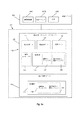
図1a−1cを参照すると、ブロック図の形式で、対象者の1又はそれ以上のパラメータをモニタリングするための本発明に係るプローブ100の3つの例が図示されている。プローブ100は、超音波タギングベースの光学測定を実施するよう構成された測定/モニタリングユニット102を有しており、これにより、対象者の関心のある領域の中に音響放射を送るための音響トランスデューサに付随する(すなわち、これを有し又はこれに結合可能な)1又はそれ以上のポート120、関心のある領域に向けて入射光を送るための光源に付随する(すなわち、これを有し又はこれに結合可能な)少なくとも1の光出力ポート122、対象者から戻る光を受けるための光検出器に付随する(すなわち、これを有し又はこれに結合可能な)少なくとも1の光入力ポート124を有する。特に示さないが、プローブはまた、反射した音響放射を受けるための追加の音響トランスデューサを有し、又は同じ音響トランスデューサを音響放射を送信且つ受信するよう構成し得ることに留意されたい。任意に、図示しないが、プローブは、照射状態の識別とともに、その作動モードに関する表示(例えば、LEDのON/OFF/点滅)を有し得る。
Referring to FIGS. 1a-1c, three examples of a
プローブアッセンブリ100は、一般に計算システム及びロジックとして構成され、特に、光源ユニット104A及び/又は検出ユニット104B及び/又は音響発生器104C(例えば、任意の波形発生器)を有する制御ユニット104に付随させることができる。一般に、制御ユニット104は、図1a−1bに示すように測定/モニタリングユニット102に接続可能な外部ユニットとして、又は図1cに示すようにプローブアッセンブリ100の中に収容された内部ユニットとして、又は、機能的ユニット104A、104B及び104Cの部分がプローブアッセンブリ100の内部に配置される一方、残りの部分がプローブアッセンブリ100の外側に配置された混成ユニット(図示せず)として構成される。全体的又は部分的に外部ユニットとして構成される場合、プローブアッセンブリ100と外部の制御ユニット104との間の通信は、有線又は無線信号/データ送信(例えば、RF、IR、音響)とし得る。
The
好適には、(例えば、制御ユニットの中の)外部の発光部とプローブ装置の光出力ポートを結合する導光部は、小さなコアファイバ(例えば、シングルモードの50μm又は62.5μmのコアファイバ)である。(例えば、制御ユニットの中の)外部の光検出器と対応する光入力ポートとを接続する導光部に関しては、導光部は、収集効率の要求を満足するために、適切な断面寸法のコアを有する。例えば、100μm又はそれ以上の直径のコアを有するファイバ又はファイバ束を使用し得る。集光ファイバの最大直径及び開口数は、ファイバコアの中の異なる経路を伝播する光の間の光路差が、光源のコヒーレンス長よりも小さくなるように決定される。光源及び/又は検出器がプローブ100の一体化部分を形成する場合、光ファイバは除外される。電線(又はワイヤレス手段)を使用して、プローブ100又は外部の制御ユニット104をモニタに接続し、診断/モニタリング処置及び/又はその処置を実行するために選択されるパラメータに関する画像又はデータを表示する。
Preferably, the light guide that couples the external light emitter (eg, in the control unit) and the light output port of the probe device is a small core fiber (eg, a single mode 50 μm or 62.5 μm core fiber). It is. For light guides that connect external photodetectors (eg, in the control unit) and corresponding light input ports, the light guides should be of appropriate cross-sectional dimensions to meet collection efficiency requirements. Has a core. For example, a fiber or fiber bundle having a core with a diameter of 100 μm or more may be used. The maximum diameter and numerical aperture of the collection fiber are determined so that the optical path difference between light propagating through different paths in the fiber core is less than the coherence length of the light source. If the light source and / or detector forms an integral part of the
プローブ装置100はまた、内部の制御ユーティリティ126を有する。制御ユーティリティ126は、上記の特許出願公開WO2009/116029号に記載されたものと略同一となるよう構成され、それは、適切な電子ユーティリティ(ユニークな作動コードで作動するコーディングチップ)とともに組み込まれ、プローブアッセンブリが認証されているものであるか否かを識別でき;及び/又は所定の期間において特定の対象者に関して取り込まれた測定を示すデータを記録するよう構成されたメモリユニットを有する(これにより、特定の対象者の測定履歴としてこのデータを使用し得る)。このようなデータは、特定の対象者の測定履歴として、測定期間又は特定の期間又は日付に続く使用の有効期限/防止を記録するための測定として機能する。メモリユニットはまた、プローブのシリアル番号又はプローブに関連する特定の技術的パラメータ(例えば、校正)に関する情報を含むデータを保存する。
The
プローブ装置100は、2つの部分から成るアッセンブリとして構成され、一方の部分110が測定/モニタリングユニット102の部材を担持して再使用可能である一方、プローブを対象者と接触させる他方の部分150が、再使用可能な部分110の所望の結合とともに、プローブと対象者との間の所望の結合を与えるよう構成され、使い捨て可能である。プローブ装置の2つの部分110及び150は、互いに適切に取付/取り外し可能である。
The
音響放射、特に光の超音波タギングを利用した測定を実施する際に、所望の結合が確立されたことを認識すると測定を作動且つ動作させるために、(光学放射に目が晒されるのをなくし/減らすために)対象者と光出力ポートとの間のある程度の結合とともに、音響ポートと対象者との間の十分な音響結合を必要とする。本発明によれば、プローブ装置100は、上記の2つの要件、すなわち、測定/モニタリングユニット102(すなわち、再使用可能な部分110)が他の(使い捨て可能な)接触部分150に確実に適切に取り付けられること、当該接触部分150及び測定部分110がモニタリングの下で対象者に確実に付着することを満足するよう構成された、適切に設計された制御機構130を有する。理解し易くするために、機能的に異なる部分である、いわゆる測定部分及び接触部分であるプローブ100の上部及び下部110、150は、以下ではそれぞれ、再使用可能な部分及び使い捨て可能な部分と称するが、一般に、双方は使い捨て可能な部分又は再使用可能な部分とし得ることが理解できよう。
When performing measurements using acoustic radiation, especially optical ultrasonic tagging, to recognize that the desired coupling has been established, to activate and operate the measurement (to eliminate eye exposure to optical radiation). Requires sufficient acoustic coupling between the acoustic port and the subject, along with some degree of coupling between the subject and the light output port. In accordance with the present invention, the
制御機構130は、少なくとも第1の(磁気及び/又は光及び/又は圧力ベース、及び/又は機械式及び/又は電気式及び/又は電気抵抗等といった)検出アッセンブリ140を有しており、好適には、第1の検出アッセンブリと同一又は異なるタイプの少なくとも1の追加的な独立して作動可能な検出アッセンブリ180も有している。したがって、好適には、制御機構は二重検出機構であり、2つの検出アッセンブリが独立して作動し、測定処置の作動が、これら双方のアッセンブリによって適切な結合が達成されていることが検出されると可能となる。
The
図1a−1cに示すように、制御機構130の少なくとも一部が測定部110の中に配置されていることが明らかであろう。制御機構の別の実行部を、測定部110の外側であって例えば図1a及び1cに示すような結合/接触ユニット150の中に配置し得る。
It will be apparent that at least a portion of the
当然ながら、本発明は図1a−1cのブロック図に示す特定の構成に限定されず、例えば、別の可能な実施例は、図1b及び1cに示す構成の組み合わせとすることができ、すなわち、制御ユニット104が(図1cのように)プローブ100の中で一体化しており、制御機構130が、(図1bのように)結合/接触ユニット150の部分を形成しない。いる。ない。
Of course, the present invention is not limited to the specific configuration shown in the block diagrams of FIGS. 1a-1c, for example, another possible embodiment may be a combination of the configurations shown in FIGS. 1b and 1c, The
図2を参照すると、本発明の一例に係るプローブアッセンブリ100が概略的に示されている。説明をし易くするために同じ参照番号を使用して、全ての図面における共通の構成要素を特定する。プローブアッセンブリ100は、一緒に取り付けられる2つの部分、すなわち(測定ユニットを担持する/与える)再使用可能な部分110と使い捨て可能な部分150(すなわち、プローブの接触部)とから構成される。再使用可能な部分110は、中に測定/モニタリングシステムの構成要素を担持するハウジング112を有する。ハウジングは、硬質プラスチックで作製される上部カバー112Aを有する。一般に、上部カバー112Aは単一パーツ構造であるが、しかしながら、それを組み立て且つ修理し易くするために、互いに取り付け可能な複数パーツで構成し得る。さらに、ハウジングは、レーザ照射の表示、又は同じシステムに結合されたいくつかのプローブのケースの場合に作動モードの表示のためにLEDを収容でき、各プローブが、異なる色又は特徴を備えた光を発する。
Referring to FIG. 2, a
再使用可能な部分110は、さらに、ケーブル及び/又はファイバと再使用可能な部分110との結合部及び曲がり点を固定するよう構成されたひずみ解放部材114を有する。他のケーブルとともに光ファイバが部材114を通過し、光入力/出力ポート及び音響ポートが、全て以下で説明するように、レーザといった適切な光源及び超音波トランスデューサとそれぞれ結合する。本発明のいくつかの実施例では、再使用可能な部分110が超音波トランスデューサを有する一方、他の実施例では、再使用可能な部分が、再使用可能な部分110の外側に配置されたトランスデューサによって発生する超音波放射の通過に関与する1つの音響ポートのみを有することが理解されよう。さらに、ひずみ解放部材114をロックするよう使用されるひずみ解放キャップ116を図示している。キャップ116は、再使用可能な部分110の様々なバージョンを表示且つマークするよう様々な色で製造且つ組み立てし得る。
The
再使用可能な部分110は、図に示さない様々な機能的部材/ユニットを収容する。図1を参照して上述したように、このような部材/ユニットは、音響放射を送信/受信するための超音波トランスデューサ又は音響ポート、少なくとも1の光出力ポート/源、少なくとも1の光入力ポート/検出器を有する。また、再使用可能な部分は、制御機構(例えば、図3−5を参照して以下で説明するような磁気センサ、機械式マイクロスイッチ)を担持する。
The
使い捨て可能な部分150は、患者の皮膚へのプローブの付着を補助する(接着パッド及び/又はストラップといった)取付パッド152を有する。取付パッド152は、比較的大きなものである。取付パッド152は、双方がある程度患者の皮膚に換気が可能な、生物に適合した接着層と遮光性繊維層との組み合わせでできている。さらなる換気をサポート且つ提供するために、パッド152は追加的なスルーホール154を有する。パッド152は、ほぼ可撓性を有しており、その柔軟性及びその曲率に合致する患者の皮膚への付着性を促進するために、パッドはその周縁に追加的な切欠部156を有する。一方、使い捨て可能な部分150は、再使用可能な部分110への固定支持部として機能し、一方で、患者の皮膚へのプローブの結合部として(接着剤として)機能する。この目的のために、使い捨て可能な部分150は、中に配置される再使用可能なユニットの幾何学的形態にしたがって構成された開口部を囲む支持フレーム160を有する。フレーム160は、適切に間隔を空けたロック部材162、164、166を備えて形成され、前記開口部に配置された場合にロック部材が再使用可能な部分110を保持する。特に、支持フレーム160は、一緒になって再使用可能な部分110を所定の位置にしっかりと固定して位置決めする、正面ロック162、複数の側面ロック164及び背面支持部166を有する。正面ロック162は前方への移動を防止し、また、患者の皮膚に押し付けられたときに、再使用可能な部分110の正面に反対圧力を与える。側面ロック164は、(側面に向かう)横軸に沿った再使用可能なユニットの移動を防止し、また、患者の皮膚に押し付けられたときにロックし再使用可能なユニットへの大きな逆圧を与える。側面ロック164は、好適には、再使用可能なユニットの簡易な取付及び片手での取り外しが可能なように設計されている。背面支持部166は、再使用可能な部分110の後方への移動を防ぎ、以下で説明するように、使い捨て可能な部分150の中に嵌め込まれたときに所定の位置に再使用可能な部分110を案内する。
The
上述したように、プローブ装置は、少なくとも磁気検出アッセンブリ140を有する制御機構を有する。図2では、プローブの使い捨て可能な部分150に付随するこのような機構の一部が部分的にみられる。
As described above, the probe apparatus has a control mechanism having at least the
図3を参照すると、図2のプローブアッセンブリ100の裏側の面が、概略的に示されている。この図は、使い捨て可能なユニット150の各開口部の中に配置され/各開口部によって保持され、そして接着性パッド152によって囲まれた再使用可能なユニットのハウジング112を示す。再使用可能なユニットのハウジング112の下面は、弾性材料でできた、使い捨て可能なユニットのフレームの開口部によって受容されるよう構成されたカバー112Bを有する。また、下部カバー112Bは、周囲環境から再使用可能なユニットを保護する(耐水性及び防塵性)よう使用される。下部カバー112Bは、音響ポート120(又は場合によっては音響(超音波)トランスデューサ)、光入力ポート124及び光出力ポート122を保持する。図にさらに示すように、使い捨て可能なユニット150に組み込まれた磁気アッセンブリ140の部分140Aは、磁性部材170(例えば、永久磁石)を保持するホルダ部材172を有する。その構成は、磁石170が使い捨て可能なユニットの中に取り付けられており、再使用可能な部分110に配置された磁気アッセンブリの他の部分(ここでは図示せず)と整列しているような構成である。
Referring to FIG. 3, the rear surface of the
本発明の非限定的な実施例によれば、再使用可能なユニットのハウジングの下面(例えば、カバー112B)は、対象者と接触し対象者に押し付けられたときに、カバーの変位/変形が可能となるよう構成されており、再使用可能なユニットが対象者に向けて移動する。この目的のために、カバー112Bは、適切な弾性/変形可能な材料(例えば、ゴム又はシリコーンといったエラストマー材料)でできており、また場合により、開口部に出入りするようわずかに移動できるよう幾何学的に設計されている(例えば、いくぶん湾曲した外面を有する)。さらに以下で説明するように、この構成は、再使用可能なユニットと対象者との所望の接触が達成するときのみに測定が可能となり、ダブルアッセンブリの制御機構によって識別可能となることを目的とする。したがって、プローブ装置が対象者と接触し、機械的圧力が加えられるときに、再使用可能なユニット並びにそれに応じて音響要素(ポート/トランスデューサ)及び光学要素(光入力ポート)が患者の皮膚に向かって押され、これにより、所望の付着を与えてモニタリング処置が開始し得る。装置が対象者から離れるときに、下部カバー112Bがその初めの形状(例えば、非変形状態)に戻る。本発明のいくつかの実施例では、所定の位置に固定される硬質/非弾性材料でカバー112Bを構成でき、例えば、機械式マイクロスイッチ機構(別の図では番号180が付されている)を使用しない場合、又は機械式マイクロスイッチ機構を別の移動パーツによって作動する異なる構成で使用する場合、カバーの移動を必要としないことに留意されたい。
According to a non-limiting embodiment of the present invention, the lower surface of the housing of the reusable unit (eg, the
使い捨て可能なユニットは、特に、図4に示されており、制御機構の一部を形成する磁石170及び磁石ホルダ172を有する磁気アッセンブリ140Aを示している。図示するように、磁石ホルダ172は、ロッド状の部材172Aを有しており、その両端172B及び172Cが、例えばフレーム160といった使い捨て可能なユニットの対向する側壁に取り付けられており、磁石170を担持する部分172Dを有する。図3及び4に示すように、この構成によれば、磁石170が使い捨て可能なユニットの下面から突出するようになっている。またこの構成によれば、磁石170がロッド状の保持部材によって規定される軸に対して回動するようなっている。結果として、プローブ装置が作動状態になり対象者に押し付けられるときに、これによって磁石が回動する。
The disposable unit is shown in particular in FIG. 4 and shows a
1つの考えられる実施例によれば、ロッド状部材172Aの少なくとも磁石担持部172Dが、プローブ100が対象者に押し付けられるときに磁石担持部が変形して磁石が回転するように、弾性/変形可能な材料でできている。代替的又は追加的に、ロッド状部材172Aは回転可能であり、これにより、プローブが対象者の皮膚に接触するときに、磁石担持部172Dが押されることによりロッド172Bが回転し、磁石の回転にさらに寄与する。
According to one possible embodiment, at least the magnet carrier 172D of the rod-like member 172A is elastic / deformable so that when the
したがって、使い捨て可能なユニット150の磁気アッセンブリ140Aは、その中の磁石が再使用可能なユニットに向けて移動でき及び再使用可能なユニットから離れることで、再使用可能なユニットに組み込まれた磁気アッセンブリ部分の検出部材に向けて移動し及び検出部材から離れるように構成される。再使用可能なユニットに向けた磁石のこの移動により、磁石170が、再使用可能なユニットの中に配置された磁気検出部材の検出領域の中に位置するようになり、これにより、プローブが、制御機構の状態の1つである、対象者の皮膚に十分に近接していることを表示する。
Thus, the
図5及び6は、本発明の考えられる実施例に係るプローブアッセンブリ100の側断面図である。2つの制御機構140、180を、2つの図に特に示す。この特定且つ非限定的な例では、プローブアッセンブリが、放射が発生する前に安全の二重チェックを提供するよう構成される。既に説明したように、制御機構により、モニタリング処置の間に使用される放射の安全な適用が可能となり、制御機構の作動位置によってプローブアッセンブリが作動するのを防止し、すなわち、プローブアッセンブリをその作動不能状態に維持する一方、その非作動位置では、制御機構によりプローブアッセンブリが作動し得る。図5は、2つの制御機構140、180の作動状態を示しており、これらの機構がプローブ100からの(光学的又は音響的な)放射作動を防止し、図6は、制御機構の非作動状態を示しており、制御機構が中立状態となってプローブ100からの放射の安全な作動が可能となる。
5 and 6 are side cross-sectional views of a
第1の制御機構は、使い捨て可能なユニット150に配置された磁石170及び弾性磁石ホルダ172と、再使用可能なユニット110に配置され磁石との間の物理的な接触なしに磁石170に近接した磁気検出部材142とを有する(一般に近接タイプの)磁気検出アッセンブリ140である。プローブアッセンブリ100が対象者に適切に付着していない場合、弾性磁石ホルダ172がその非作動位置を維持し、使い捨て可能なユニットの外側に下がっている。結果として、磁石170の磁場は磁気センサ142によって検出されず、したがって磁気センサは作動信号を発生させない。その一方で、プローブアッセンブリが適切に(しっかりと)対象者に付着している場合、図6に示すように、磁気ホルダ172がその向きを作動位置に変え、結果として磁石170の磁場が磁気センサ142を始動させ、放射源の作動が可能となる。留意すべきは、磁気センサ142のヒステリシスの検出範囲は、磁石170の作動状態角度の角度範囲を与えるように選択され、これは磁石ホルダ172の位置に依存することで、患者の身体の広範囲の曲がりに亘ってプローブの使用が可能となることである。
The first control mechanism is in proximity to the
留意すべきは、一般的に、追加的に又は代替的に、制御機構は、容量性、光学、超音波、機械式、マイクロスイッチ、圧力又はRFIDベースのアッセンブリといった、適切な近接検出アッセンブリを有することである。このような検出アッセンブリの構成及び作動は、それ自体知られており、本発明の部分を形成しないため、詳細に説明することを要しない。 It should be noted that, in general, additionally or alternatively, the control mechanism has a suitable proximity detection assembly such as capacitive, optical, ultrasonic, mechanical, microswitch, pressure or RFID based assembly. That is. The construction and operation of such detection assemblies are known per se and do not form a part of the present invention and therefore need not be described in detail.
追加の制御機構は、機械式マイクロスイッチ機構180とし得る。この機構は、再使用可能なユニット110に配置されており、マイクロスイッチ182及び弾性レバー184を有する。後者は、マイクロスイッチ182と整列するように、下部カバー112Bに配置されている。この機構は弾性下部カバー112Bの弾性を利用する。図5に示すように、プローブアッセンブリ100が患者の組織に適切に付着していない場合、再使用可能なユニット110の弾性下部カバー112Bが、再使用可能なユニットの筐体から飛び出ている。この状態では、弾性下部カバー112Bに取り付けられた弾性レバー184が、その上方に位置するマイクロスイッチ182から隔たっているためにこれを押さず、これにより、マイクロスイッチ182は作動しない。その一方、プローブアッセンブリ100が、図6に示すように適切に(しっかりと)患者に付着する場合、弾性下部カバー112Bが再使用可能なユニット110の内部の空洞の中に押され、弾性レバー184がマイクロスイッチ182を押すことで、マイクロスイッチ182を作動させて各電気回路(図示せず)を閉じる。留意すべきは、レバー184の弾性特性及び構造が、マイクロスイッチ182のストロークよりも大きなストロークを与えることで、下部カバー112B及びマイクロスイッチの有効ストローク範囲が延びることである。
The additional control mechanism may be a
図5は、さらに、超音波ポート/トランスデューサ120、光出力ポート122及び光入力ポート124と同時に、既に説明したひずみ解放部材114及びキャップ116を有する再使用可能なユニットのさらなる詳細を示す。また、この特定的ではあるが非限定的な例に示すように、光出力ポート122及び光入力ポート124は、長手棒(導光路)123、125をそれぞれ終端としており、それらに沿って送受信される光が通過する。レンズ/プリズム126、128が、光源/検出器及び再使用可能なパーツ110間に介在する光ファイバ(図示せず)から/光ファイバに向けて、ロッドに/ロッドから光の向きを変えるよう使用される。
FIG. 5 further illustrates further details of the reusable unit having the
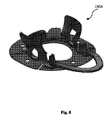
図7及び8を参照すると、本発明の一実施例に係る2パーツ構成のプローブ100Aの別の例が示されている。この特定の構成では、制御機構が、再使用可能な部分110Aの内部のみに配置されており、使い捨て可能な部分150Aが機械的な支持を与える。特に、再使用可能な部分110Aは、図7に示すように、磁気検出アッセンブリを有しないこと、すなわち、磁気センサ142及びそれに付随して存在する回路を有しないことを除いて、図5及び6の部分110と同じ構造を有するよう構成される。代替的に、図7のプローブの制御機構が、図5及び6を参照して説明したのと同じパーツ及び形態を有する機械式のマイクロスイッチ機構180を含んでおり、機構180が再使用可能なユニット110Aに配置されており、マイクロスイッチ182及び弾性レバー184を含んでいる。弾性レバーは下部カバー112Bに設けられており、マイクロスイッチ182と整列している。この機構は、マイクロスイッチを押す弾性的な下部カバー112Bの弾性を利用する。
7 and 8, another example of a two-
使い捨て可能な部分150Aは、図8に示すように、この特定の構成では磁気検出アッセンブリが無いため磁石ホルダ172も磁石170も有しないことを除いて、図4に示す使い捨て可能な部分と同じパーツ及び形態を有している。プローブ100Aの制御機構180は、図5及び6を参照して上述したのと同じ方法で機能する。
The
本発明の実施例に係るプローブの再使用可能な部分110Bの他の例を示す図9a及び9bを参照する。制御機構は、再使用可能な部分110Bの内部に配置された2つの機械式マイクロスイッチ180.1及び180.2を有している。再使用可能な部分110Bは、図8に示すように、使い捨て可能な部分150Aとともに使用され得る。図9bでは、マイクロスイッチ180.1及び180.2が、弾性的な下部カバー112Bと直接的又は(例えば、トランスデューサ構造を介して)間接的に接触するよう配置されており、それらが再使用可能な部分110Bの天井部分に押し付けられたときに、制御状態が作動する。この構造に弾性レバー184は無い。再使用可能な部分110Bの天井部分のフェンスが、弾性的な下部カバー112Bの動きを規制し、マイクロスイッチ及び光学レンズの離れた状態を保持する。これらの特定の例では、2つのマイクロスイッチ180.1、180.2が双方共に作動するときのみに、プローブが作動して音響及び光学放射を放射させ得る。この双対構成は、一面では作動の安全な制御を提供する点で有利であり、その反面、市販されているコスト効果のあるマイクロスイッチを使用し得る。制御ユニット又はプローブアッセンブリの別の場所で使用される制御ロジックは周期的に変動し、2つのマイクロスイッチが同じ近接表示を与え、これにより、何らかの不整合が障害として表示される。したがって、手入れをすべきであり装置を修理すべきであるという、ユーザに対する警告として機能する。留意すべきは、安全な作動を確実にするために、同様な制御ロジックシステムを具えた2以上のスイッチを使用し得ることである。
Reference is made to FIGS. 9a and 9b illustrating another example of a reusable portion 110B of a probe according to an embodiment of the present invention. The control mechanism has two mechanical microswitches 180.1 and 180.2 arranged inside the reusable part 110B. The reusable portion 110B can be used with a
図10は、本発明の一実施例に係る1つのパーツ又は2つのパーツを有するプローブアッセンブリの構成のより構造的な例の概略的且つ機能的な図を示す。この図において、プローブアッセンブリ100Cは、再使用可能な部分110C及び使い捨て可能な部分150Cを有する2つのパーツから成るプローブとして構成される。再使用可能な部分110Cでは、プローブアッセンブリが、対象者の関心のある領域に/領域から音響放射を送受信するための音響トランスデューサに付随する(すなわち、有する又は結合可能な)、1又はそれ以上の音響ポート120を有する。また、プローブアッセンブリは、関心のある領域に向けて入射光を送るための光源に付随する(すなわち、有する又は結合可能な)少なくとも1の光出力ポート122を有する。代替的に又は再使用可能な部分に組み込まれ一体型又は外付けの光検出器に付随する光入力ポート124に加えて、プローブアッセンブリは、使い捨て可能な部分に取り付けられた1又はそれ以上の光検出器を有する。この特定の実施例では、間隔を空けた2つの検出器104.1及び104.2を示しており、被験者の異なる領域から到達する、異なる経路又は深さを通って伝播する、異なる波長/周波数といった特性のうちの、1又はそれ以上のこれらの特性を有する光を受けるよう機能する。一方又は双方の検出器は、タギングされた又はタギングされていない光を解析するために使用し得る。
FIG. 10 shows a schematic and functional diagram of a more structural example of a one-part or two-part probe assembly configuration according to one embodiment of the present invention. In this figure, the
この特定の例では、図に示すように、制御機構が、発光体を制御するためのロジック素子(マイクロコントローラ)192を備えた発光素子(例えばLED)190、発光体及び/又は光検出器140.1及び140.2のための電源194(例えばバッテリ)、圧力センサ196及び/又はオーム計198(又は抵抗計又は電流計)のうちの1又はそれ以上の構成要素を有する。論理制御器は、発光素子によって送信される信号を所定のコードにエンコード又は変換するよう構成されている。
In this particular example, as shown in the figure, the control mechanism is a light emitting device (eg, LED) 190 with a logic device (microcontroller) 192 for controlling the light emitter, light emitter and / or
付随する論理制御器192ともに発光体190を、使い捨て可能な部分からの情報を再使用可能又は制御ユニット(104)に無線送信するよう使用できる。この情報は、使い捨て可能な部分の識別のためのシリアル番号、使い捨て可能な部分が認証されたことを認証するための認証信号、使い捨て可能な部分(又はロジック素子)の作動開始からの時間に関するカウンタ表示器、再使用可能な部分及び使い捨て可能な部分間の結合の程度を示す信号、プローブアッセンブリ(再使用可能及び/又は使い捨て可能な部分)の組織との間の結合の程度を示す信号、光検出器によって検出される光情報等を含んでいる。このような結合の程度は、圧力センサ196又はオーム計198、又は本発明で使用され当技術分野で知られた他の近接性又は付着検出アッセンブリによって測定され、光学部材を始動させるよう論理制御器によってエンコードされ、再使用可能な部分の内部又は外部に配置された制御ユニットに光学的に送信され得る。これにより、適切に絶縁されていない場合に組織に電流を知らずに結合する電線又は電気的結合なしに、情報の送信が可能となる。本発明によれば、光学部材190によって送信される情報及び光出力ポート122から発せられた光信号の双方を受信するために同じ光検出器を使用し得る。光学部材の作動は、ポート122に含まれる/結合される光源の作動と同期され得る。この同期は、まず、光がポート122から発せられていないことを使い捨て可能な部分の光検出器によって検出することで、次に、論理制御器192を通して光学部材190の作動を開始させることでなされ得る。代替的に、通信/同期信号を光出力ポート122から発して、光出力ポート122が特定の時間作動していないことを表示でき、LED190が作動し得る。留意すべきは、光学部材190によって実現され、上記の情報を送信するよう使用される光リンクの代わりに、他のワイヤレスリンク及びRFといった技術を使用できることである。
With the associated
圧力センサ196は、すでに言及した近接及び/又は付着検出アッセンブリの代わりに又はこれに加えて使用できる。圧力センサ196は、プローブアッセンブリが組織に適用する圧力の大きさを測定且つ通信するために使用できる。測定された圧力は、(上記のように光学部材190の作動を通して)制御ユニットに送信される。圧力が所定の最低閾値又は最高閾値よりも低いか又は高い場合、論理制御器192がユーザに警告を表示でき、又はプローブアッセンブリの作動を完全に停止できる。
The
オーム計198(又は抵抗/電流計)は、使い捨て可能な部分150C及び組織間、又は使い捨て可能な部分に取り付けられた検出電極間の抵抗を測定し、(例えば、光学部材190の作動を通して)制御ユニットに信号を送る。この信号は、プローブアッセンブリ及び組織間の結合、ゲルの量、プローブアッセンブリと組織との間に位置する他の結合物質又は媒体を表示できる。抵抗が所定の最低/最高閾値よりも低いか又は高い場合、論理制御器192がユーザに警告を表示でき、又はプローブアッセンブリの作動を完全に停止できる。
The ohmmeter 198 (or resistance / ammeter) measures and controls the resistance between the
上記の例(例えば図5、6、7、9)では、光源(104A)が、プローブ(再使用可能な部分)の外部の制御ユニットの内部に配置されたものとして例示されている。しかしながら上記のように、光源及び/又は音響トランスデューサ及び/又は検出ユニットを具える制御ユニット、又はその部分は、温度といったプローブ内部の光源を作動させるための条件が満足する限り、例えば再使用可能な部分に取り付けて、プローブアッセンブリの一体化した部分として形成し得る。これは、図11に示されており、光源104Aが使い再使用可能な部分110Dの内部に置かれている。光出力ポート122、光入力ポート124及び音響ポート(又はトランスデューサ)120もまた、この図に示す。光源104Aは、エラストマーの下部カバー112Dに配置されており、超音波トランスデューサ及び光入力ポートとともに対象者に押し付けられる。再使用可能なハウジング110Dは2つの部分、すなわち、光源104Aに結合され光源104Aとともに移動してヒートシンクとして機能する金属部品、エラストマーの下部カバー112D及び構成全体を閉じるプラスチック部品から成る。
In the above examples (eg, FIGS. 5, 6, 7, and 9), the light source (104A) is illustrated as being located inside the control unit outside the probe (reusable part). However, as mentioned above, the control unit comprising a light source and / or acoustic transducer and / or detection unit, or part thereof, is reusable, for example, as long as the conditions for operating the light source inside the probe, such as temperature, are satisfied. It can be attached to the part and formed as an integral part of the probe assembly. This is illustrated in FIG. 11 where the
Claims (28)
前記対象者の関心のある領域の中に音響放射を伝えるための少なくとも1の音響ポートと、前記関心のある領域に向けて入射光を伝えるための少なくとも1の光出力ポートと、前記対象者から戻る光を受けるための少なくとも1の光入力ポートとを具えるモニタリングアッセンブリと、
近接付着及び信号の質の状態のうちの少なくとも一方を検出するよう構成され、前記プローブアッセンブリ及び前記対象者間の結合状態を制御するよう構成されて、前記モニタリングアッセンブリの作動を制御し得る少なくとも1の検出アッセンブリを具える少なくとも1の制御機構と、
を具えることを特徴とするプローブ。 A probe for use in monitoring one or more parameters of a subject, the probe comprising:
At least one acoustic port for transmitting acoustic radiation into the region of interest of the subject, at least one light output port for transmitting incident light toward the region of interest, from the subject A monitoring assembly comprising at least one light input port for receiving the returning light;
At least one configured to detect at least one of proximity attachment and signal quality condition, and configured to control a coupling state between the probe assembly and the subject to control operation of the monitoring assembly; At least one control mechanism comprising a detection assembly of
A probe comprising:
第1の可撓性部分、及び前記モニタリングアッセンブリが取り付けられる第2の部分を具えており、
前記対象者に前記プローブアッセンブリを押し付けることで前記可撓性部分が変形し、これにより、前記モニタリングアッセンブリと近接検出アッセンブリによって検出可能な前記対象者との間の距離を縮めることを特徴とするプローブ。 The probe according to claim 1, wherein
A first flexible portion and a second portion to which the monitoring assembly is attached;
Pressing the probe assembly against the subject deforms the flexible portion, thereby reducing the distance between the monitoring assembly and the subject that can be detected by the proximity detection assembly. .
前記磁気センサが、前記磁気センサの近くに検出領域を規定し、磁場が前記磁気センサの前記検出領域と重なる場合に前記磁石の磁場を検出するよう構成されることを特徴とするプローブ。 3. The probe of claim 2, wherein the proximity detection assembly comprises a magnetic detection assembly comprising a magnet carried by the first flexible portion and a magnetic sensor disposed on the second portion. ,
The probe, wherein the magnetic sensor defines a detection region near the magnetic sensor, and is configured to detect the magnetic field of the magnet when the magnetic field overlaps the detection region of the magnetic sensor.
前記制御機構が、さらに、前記少なくとも1の検出アッセンブリと比較して同一又は異なる型の追加の検出アッセンブリであって、前記少なくとも1の検出アッセンブリから独立して作動可能な追加の検出アッセンブリを具え、
前記追加の検出アッセンブリが、前記プローブと前記対象者との間の結合状況を制御するよう構成され、
少なくとも2の前記独立した検出アッセンブリが、前記モニタアッセンブリの作動を制御可能であることを特徴とするプローブ。 The probe according to any one of claims 1 to 4,
The control mechanism further comprises an additional detection assembly of the same or different type compared to the at least one detection assembly, the additional detection assembly operable independently of the at least one detection assembly;
The additional detection assembly is configured to control a coupling situation between the probe and the subject;
A probe, wherein at least two of the independent detection assemblies are capable of controlling operation of the monitor assembly.
前記機械的アッセンブリが、前記可撓性部分に配置されたスイッチを具えており、前記対象物に向けて前記プローブアッセンブリを押し付けることにより前記可撓性部分を変形させ、これにより、前記スイッチを作動させて前記モニタリングアッセンブリが作動し得ることを特徴とするプローブ。 The probe of claim 6, comprising a first flexible portion, and a second portion to which the monitoring assembly is attached.
The mechanical assembly includes a switch disposed on the flexible portion, and deforms the flexible portion by pressing the probe assembly toward the object, thereby actuating the switch. And the monitoring assembly is operable.
前記第1及び第2の部分が、互いに取り外し可能に取り付け可能であることを特徴とするプローブ。 The probe according to any one of claims 2 to 7,
The probe according to claim 1, wherein the first and second portions are detachably attachable to each other.
音響及び光学放射を前記対象者に放射するよう構成されたモニタリングアッセンブリと、作動時に前記プローブが前記対象者に面する可撓性部分と、を担持する部分と、
前記可撓性部分に少なくとも部分的に配置された少なくとも1の近接検出アッセンブリを具える少なくとも1の制御機構であって、前記プローブアッセンブリを前記対象者に押し付けることで前記可撓性部分が変形することにより、前記モニタリングアッセンブリと前記少なくとも1の近接検出アッセンブリによって検出可能な前記対象者との間の距離を減らし、これにより、前記プローブと前記対象者との間の結合の状態を制御し得ることで、前記モニタリングアッセンブリの作動を制御することを特徴とするプローブ。 A probe for use in monitoring one or more parameters of a subject, the probe comprising:
A portion carrying a monitoring assembly configured to emit acoustic and optical radiation to the subject, and a flexible portion where the probe faces the subject in operation;
At least one control mechanism comprising at least one proximity sensing assembly at least partially disposed on the flexible portion, wherein the flexible portion is deformed by pressing the probe assembly against the subject; Thereby reducing the distance between the monitoring assembly and the subject detectable by the at least one proximity sensing assembly, thereby controlling the state of coupling between the probe and the subject. And a probe for controlling the operation of the monitoring assembly.
音響及び光学放射を前記対象者に放射するよう構成されたモニタリングアッセンブリと、作動時に前記プローブが前記対象者に面する可撓性部分と、を担持する部分と、
それぞれ第1及び第2のタイプと同一又は異なる少なくとも第1及び第2の検出アッセンブリを具える少なくとも第1及び第2の制御機構であって、それぞれが、前記プローブと前記対象者との間の結合の状態を制御するよう独立して作動可能であり、前記少なくとも第1及び第2の異なる検出アッセンブリが、前記状態が満足するものではないと特定する場合に、前記モニタリングアッセンブリの作動を制御する、制御機構とを具えており、
前記少なくとも第1及び第2の検出アッセンブリの少なくとも一方が、前記可撓性部分に少なくとも部分的に配置された近接検出アッセンブリであり、前記対象者に前記プローブを押し付けることにより前記可撓性部分を変形させ、これにより、前記モニタリングアッセンブリと前記少なくとも1の近接検出アッセンブリによって検出可能な前記対象者との間の距離を減らすことを特徴とするプローブ。 A probe for use in monitoring one or more parameters of a subject, the probe comprising:
A portion carrying a monitoring assembly configured to emit acoustic and optical radiation to the subject, and a flexible portion where the probe faces the subject in operation;
At least first and second control mechanisms each comprising at least first and second detection assemblies that are the same as or different from the first and second types, respectively, each between the probe and the subject Operate independently to control the state of coupling and control the operation of the monitoring assembly when the at least first and second different detection assemblies identify that the state is not satisfactory A control mechanism,
At least one of the at least first and second detection assemblies is a proximity detection assembly at least partially disposed on the flexible portion, and pressing the probe against the subject causes the flexible portion to move. A probe that is deformed, thereby reducing the distance between the monitoring assembly and the subject detectable by the at least one proximity detection assembly.
Applications Claiming Priority (3)
| Application Number | Priority Date | Filing Date | Title |
|---|---|---|---|
| US201361782641P | 2013-03-14 | 2013-03-14 | |
| US61/782,641 | 2013-03-14 | ||
| PCT/IL2014/050280 WO2014141277A1 (en) | 2013-03-14 | 2014-03-13 | Probe for non invasive optical monitoring |
Publications (2)
| Publication Number | Publication Date |
|---|---|
| JP2016513527A true JP2016513527A (en) | 2016-05-16 |
| JP2016513527A5 JP2016513527A5 (en) | 2017-04-06 |
Family
ID=50513397
Family Applications (1)
| Application Number | Title | Priority Date | Filing Date |
|---|---|---|---|
| JP2015562560A Pending JP2016513527A (en) | 2013-03-14 | 2014-03-13 | Probe for non-invasive optical monitoring |
Country Status (6)
| Country | Link |
|---|---|
| US (1) | US20160022182A1 (en) |
| EP (1) | EP2967335A1 (en) |
| JP (1) | JP2016513527A (en) |
| CN (1) | CN105188518A (en) |
| HK (1) | HK1216597A1 (en) |
| WO (1) | WO2014141277A1 (en) |
Families Citing this family (6)
| Publication number | Priority date | Publication date | Assignee | Title |
|---|---|---|---|---|
| AU2014293401B2 (en) | 2013-07-22 | 2019-05-02 | Quvium Uk Ltd | Cough detection, analysis, and communication platform |
| JP6663035B2 (en) | 2016-03-09 | 2020-03-11 | コーニンクレッカ フィリップス エヌ ヴェKoninklijke Philips N.V. | Fetal imaging system and method |
| CN108780036B (en) * | 2018-04-23 | 2021-10-22 | 深圳达闼科技控股有限公司 | Optical detection equipment and detection method |
| EP3705041A1 (en) * | 2019-03-05 | 2020-09-09 | Luciole Medical AG | Sensor assembly |
| CN111110234B (en) * | 2019-12-11 | 2021-12-14 | 广州医科大学 | Skin jaundice detector and detection method |
| CN113749653A (en) * | 2020-06-01 | 2021-12-07 | 江苏赛腾医疗科技有限公司 | Blood oxygen monitoring equipment and blood oxygen monitoring method |
Citations (6)
| Publication number | Priority date | Publication date | Assignee | Title |
|---|---|---|---|---|
| JP2001070266A (en) * | 1999-09-02 | 2001-03-21 | Denso Corp | Biological signal detecting device |
| JP2005130969A (en) * | 2003-10-29 | 2005-05-26 | Seiko Instruments Inc | Circulatory dynamic measuring instrument |
| JP2006247133A (en) * | 2005-03-10 | 2006-09-21 | Sharp Corp | Biomedical signal measuring device, method for measuring biomedical signal, and computer program |
| JP2007536053A (en) * | 2004-05-06 | 2007-12-13 | コーニンクレッカ フィリップス エレクトロニクス エヌ ヴィ | Protection mechanism for spectroscopic analysis of biological tissue |
| WO2009116029A2 (en) * | 2008-03-17 | 2009-09-24 | Or-Nim Medical Ltd. | Apparatus for non invasive optical monitoring |
| WO2011033628A1 (en) * | 2009-09-16 | 2011-03-24 | コニカミノルタセンシング株式会社 | Living organism information measurement device, living organism information measurement system, and communication method and usage method for living organism information measurement device |
Family Cites Families (9)
| Publication number | Priority date | Publication date | Assignee | Title |
|---|---|---|---|---|
| CN1334949A (en) * | 1998-03-20 | 2002-02-06 | 弗西蒂技术有限公司 | Concurrent display and data communicating system and method using LEDs |
| ATE374566T1 (en) * | 1998-11-16 | 2007-10-15 | S P O Medical Equipment Ltd | SENSOR FOR RADIATION BASED DIAGNOSTICS |
| US7359741B2 (en) * | 1999-11-15 | 2008-04-15 | Spo Medical Equipment Ltd. | Sensor and radiance based diagnostics |
| US8131332B2 (en) * | 2002-04-04 | 2012-03-06 | Veralight, Inc. | Determination of a measure of a glycation end-product or disease state using tissue fluorescence of various sites |
| DK1675501T3 (en) | 2003-09-12 | 2013-11-18 | Or Nim Medical Ltd | Non-invasive optical monitoring of an area of interest |
| ES2427546T3 (en) | 2005-03-16 | 2013-10-30 | Or-Nim Medical Ltd. | Non-invasive measurements in the body of a human |
| CN101997602A (en) * | 2009-08-18 | 2011-03-30 | 深圳市理邦精密仪器股份有限公司 | Infrared radio communication system applied to medical equipment |
| CN201879671U (en) * | 2010-11-10 | 2011-06-29 | 南京信息工程大学 | Pulse signal acquisition device based on infrared communication technology |
| CN102824189B (en) * | 2012-08-20 | 2014-12-10 | 深圳市理邦精密仪器股份有限公司 | Ultrasonic probe timely transmitting and receiving method and device |
-
2014
- 2014-03-13 JP JP2015562560A patent/JP2016513527A/en active Pending
- 2014-03-13 US US14/775,380 patent/US20160022182A1/en not_active Abandoned
- 2014-03-13 WO PCT/IL2014/050280 patent/WO2014141277A1/en active Application Filing
- 2014-03-13 CN CN201480014397.8A patent/CN105188518A/en active Pending
- 2014-03-13 EP EP14718179.6A patent/EP2967335A1/en not_active Withdrawn
-
2016
- 2016-04-25 HK HK16104687.2A patent/HK1216597A1/en unknown
Patent Citations (6)
| Publication number | Priority date | Publication date | Assignee | Title |
|---|---|---|---|---|
| JP2001070266A (en) * | 1999-09-02 | 2001-03-21 | Denso Corp | Biological signal detecting device |
| JP2005130969A (en) * | 2003-10-29 | 2005-05-26 | Seiko Instruments Inc | Circulatory dynamic measuring instrument |
| JP2007536053A (en) * | 2004-05-06 | 2007-12-13 | コーニンクレッカ フィリップス エレクトロニクス エヌ ヴィ | Protection mechanism for spectroscopic analysis of biological tissue |
| JP2006247133A (en) * | 2005-03-10 | 2006-09-21 | Sharp Corp | Biomedical signal measuring device, method for measuring biomedical signal, and computer program |
| WO2009116029A2 (en) * | 2008-03-17 | 2009-09-24 | Or-Nim Medical Ltd. | Apparatus for non invasive optical monitoring |
| WO2011033628A1 (en) * | 2009-09-16 | 2011-03-24 | コニカミノルタセンシング株式会社 | Living organism information measurement device, living organism information measurement system, and communication method and usage method for living organism information measurement device |
Also Published As
| Publication number | Publication date |
|---|---|
| HK1216597A1 (en) | 2016-11-25 |
| EP2967335A1 (en) | 2016-01-20 |
| CN105188518A (en) | 2015-12-23 |
| WO2014141277A1 (en) | 2014-09-18 |
| US20160022182A1 (en) | 2016-01-28 |
Similar Documents
| Publication | Publication Date | Title |
|---|---|---|
| JP2016513527A (en) | Probe for non-invasive optical monitoring | |
| US9078617B2 (en) | Apparatus for non-invasive optical monitoring | |
| US11786152B2 (en) | Tissue oximetry probe with tissue marking feature | |
| US20210212616A1 (en) | Wearable device with multimodal diagnostics | |
| KR101964257B1 (en) | A high intensity focused ultrasound device with built-in unit for detecting the transducer's movement position | |
| CN104939883B (en) | Instrument and method for tissue thickness's sensing | |
| JP6496754B2 (en) | Positioning wearable devices for data collection | |
| US10555769B2 (en) | Flexible circuits for electrosurgical instrument | |
| JP2016517310A (en) | Self-contained regional oxygen saturation measurement method | |
| JP2016131883A (en) | Powered surgical stapling device | |
| CN108451546B (en) | Laser interlock system for medical use | |
| JP2005506854A (en) | Laryngoscope | |
| CN109069011B (en) | Optical measuring device for cardiovascular diagnosis | |
| JP2020185449A (en) | Continuous glucose monitoring on-body sensor having visual display | |
| KR20200142602A (en) | System and method for determining structural characteristics of an object | |
| JP2018192248A (en) | Powered surgical stapling device | |
| EP3432789A1 (en) | Rollable biometric measuring device | |
| CN114072659A (en) | Determination of structural properties of an object | |
| US20150359471A1 (en) | Composite medical examination device | |
| US20190223837A1 (en) | Disposable probe | |
| WO2017038908A1 (en) | Photoacoustic imaging device | |
| KR20210016559A (en) | Optical blood pressure measurement device and method | |
| US20210295978A1 (en) | System and Method for Controlling Operability of Multiple Medical Devices | |
| JP2012013419A (en) | Urine sugar meter | |
| US20200164219A1 (en) | Probe unit and acoustic wave receiving system |
Legal Events
| Date | Code | Title | Description |
|---|---|---|---|
| A521 | Request for written amendment filed |
Free format text: JAPANESE INTERMEDIATE CODE: A523 Effective date: 20160210 |
|
| A521 | Request for written amendment filed |
Free format text: JAPANESE INTERMEDIATE CODE: A523 Effective date: 20170306 |
|
| A621 | Written request for application examination |
Free format text: JAPANESE INTERMEDIATE CODE: A621 Effective date: 20170306 |
|
| A977 | Report on retrieval |
Free format text: JAPANESE INTERMEDIATE CODE: A971007 Effective date: 20180119 |
|
| A131 | Notification of reasons for refusal |
Free format text: JAPANESE INTERMEDIATE CODE: A131 Effective date: 20180130 |
|
| A601 | Written request for extension of time |
Free format text: JAPANESE INTERMEDIATE CODE: A601 Effective date: 20180419 |
|
| A601 | Written request for extension of time |
Free format text: JAPANESE INTERMEDIATE CODE: A601 Effective date: 20180621 |
|
| A521 | Request for written amendment filed |
Free format text: JAPANESE INTERMEDIATE CODE: A523 Effective date: 20180726 |
|
| A02 | Decision of refusal |
Free format text: JAPANESE INTERMEDIATE CODE: A02 Effective date: 20181204 |