JP2016508917A - Handle hand detection system - Google Patents
Handle hand detection system Download PDFInfo
- Publication number
- JP2016508917A JP2016508917A JP2015557218A JP2015557218A JP2016508917A JP 2016508917 A JP2016508917 A JP 2016508917A JP 2015557218 A JP2015557218 A JP 2015557218A JP 2015557218 A JP2015557218 A JP 2015557218A JP 2016508917 A JP2016508917 A JP 2016508917A
- Authority
- JP
- Japan
- Prior art keywords
- sensor
- detection system
- disposed
- handle
- mat
- Prior art date
- Legal status (The legal status is an assumption and is not a legal conclusion. Google has not performed a legal analysis and makes no representation as to the accuracy of the status listed.)
- Granted
Links
Images


Classifications
-
- B—PERFORMING OPERATIONS; TRANSPORTING
- B62—LAND VEHICLES FOR TRAVELLING OTHERWISE THAN ON RAILS
- B62D—MOTOR VEHICLES; TRAILERS
- B62D1/00—Steering controls, i.e. means for initiating a change of direction of the vehicle
- B62D1/02—Steering controls, i.e. means for initiating a change of direction of the vehicle vehicle-mounted
- B62D1/04—Hand wheels
- B62D1/046—Adaptations on rotatable parts of the steering wheel for accommodation of switches
-
- B—PERFORMING OPERATIONS; TRANSPORTING
- B62—LAND VEHICLES FOR TRAVELLING OTHERWISE THAN ON RAILS
- B62D—MOTOR VEHICLES; TRAILERS
- B62D1/00—Steering controls, i.e. means for initiating a change of direction of the vehicle
- B62D1/02—Steering controls, i.e. means for initiating a change of direction of the vehicle vehicle-mounted
- B62D1/04—Hand wheels
- B62D1/06—Rims, e.g. with heating means; Rim covers
- B62D1/065—Steering wheels with heating and ventilating means
-
- G—PHYSICS
- G01—MEASURING; TESTING
- G01L—MEASURING FORCE, STRESS, TORQUE, WORK, MECHANICAL POWER, MECHANICAL EFFICIENCY, OR FLUID PRESSURE
- G01L1/00—Measuring force or stress, in general
-
- G—PHYSICS
- G01—MEASURING; TESTING
- G01L—MEASURING FORCE, STRESS, TORQUE, WORK, MECHANICAL POWER, MECHANICAL EFFICIENCY, OR FLUID PRESSURE
- G01L1/00—Measuring force or stress, in general
- G01L1/20—Measuring force or stress, in general by measuring variations in ohmic resistance of solid materials or of electrically-conductive fluids; by making use of electrokinetic cells, i.e. liquid-containing cells wherein an electrical potential is produced or varied upon the application of stress
- G01L1/205—Measuring force or stress, in general by measuring variations in ohmic resistance of solid materials or of electrically-conductive fluids; by making use of electrokinetic cells, i.e. liquid-containing cells wherein an electrical potential is produced or varied upon the application of stress using distributed sensing elements
-
- B—PERFORMING OPERATIONS; TRANSPORTING
- B60—VEHICLES IN GENERAL
- B60W—CONJOINT CONTROL OF VEHICLE SUB-UNITS OF DIFFERENT TYPE OR DIFFERENT FUNCTION; CONTROL SYSTEMS SPECIALLY ADAPTED FOR HYBRID VEHICLES; ROAD VEHICLE DRIVE CONTROL SYSTEMS FOR PURPOSES NOT RELATED TO THE CONTROL OF A PARTICULAR SUB-UNIT
- B60W40/00—Estimation or calculation of non-directly measurable driving parameters for road vehicle drive control systems not related to the control of a particular sub unit, e.g. by using mathematical models
- B60W40/08—Estimation or calculation of non-directly measurable driving parameters for road vehicle drive control systems not related to the control of a particular sub unit, e.g. by using mathematical models related to drivers or passengers
Landscapes
- Engineering & Computer Science (AREA)
- Mechanical Engineering (AREA)
- Transportation (AREA)
- Physics & Mathematics (AREA)
- Chemical & Material Sciences (AREA)
- Combustion & Propulsion (AREA)
- General Physics & Mathematics (AREA)
- Automation & Control Theory (AREA)
- Mathematical Physics (AREA)
- Steering Controls (AREA)
- Auxiliary Drives, Propulsion Controls, And Safety Devices (AREA)
- Traffic Control Systems (AREA)
- Force Measurement Appropriate To Specific Purposes (AREA)
Abstract
ハンドルの手検出システムが本明細書に開示される。このシステムは任意に、ハンドル上の運転者の手の存在及び/または位置を特定するためのシステムとともに使用され得る。このシステムは、複数の検知区域を実現するようにハンドルに配置された複数のセンサループを含むセンサマットを含む。システムが複数のセンサループを含むセンサマットを含むため、システムは、異なる設計を有するハンドルに実装され得る。システムはまた、異なる数及び/または種類(例えば、タップ検出、スワイプ検出、グリップ検出など)の検知区域を実現するように実装され得る。加えて、システムは、配線によるクロストークの可能性を減少させる方法で実装され得る。【選択図】図2AA hand detection system for a handle is disclosed herein. This system can optionally be used with a system for determining the presence and / or position of the driver's hand on the steering wheel. The system includes a sensor mat that includes a plurality of sensor loops disposed on the handle to provide a plurality of sensing areas. Because the system includes a sensor mat that includes multiple sensor loops, the system can be implemented on handles having different designs. The system may also be implemented to implement different numbers and / or types of sensing zones (eg, tap detection, swipe detection, grip detection, etc.). In addition, the system can be implemented in a manner that reduces the possibility of crosstalk due to wiring. [Selection] Figure 2A
Description
本発明は、概して、ハンドルの分野に関する。より具体的には、これは、ハンドル上の運転者の手の存在を検知するためのシステムに関する。 The present invention relates generally to the field of handles. More specifically, this relates to a system for detecting the presence of a driver's hand on a steering wheel.
従来のハンドルは、車両操作中に運転者の手の位置を検出する能力を有さない。通常の運転状態では、両手は、車両の完全に安全な制御下でハンドル上に存在するべきであり、「手をハンドルから放さない、よそ見をしない、運転に集中する」という安全標語に従っている。 Conventional handles do not have the ability to detect the position of the driver's hand during vehicle operation. Under normal driving conditions, both hands should be on the steering wheel under fully safe control of the vehicle and follow the safety slogan “Do not let go of the steering wheel, look away, concentrate on driving”.
近年、運転者の潜在的に注意をそらすものの数が増加している。携帯用電子機器(例えば、携帯電話、mp3プレーヤなど)の出現とともに、運転者にハンドルから手を放すよう働きかけるか、または誘惑するいくつかの電子機器によって注意がそらされるものがある。例えば、そのような携帯用電子機器は、携帯電話で電話をかけるために手動でダイアルするか、または電話番号を選択すること、手動でメッセージを送信し、かつ/または電子メールに返信すること、または備え付けのMP3プレーヤでどの曲をかけるか選択することを必要とし得る。 In recent years, the number of potential driver distractions has increased. With the advent of portable electronic devices (eg, mobile phones, mp3 players, etc.), some are distracted by some electronic devices that encourage or entice drivers to release their hands. For example, such a portable electronic device may manually dial or select a phone number, manually send a message and / or reply to an email to make a call on a mobile phone, Or it may be necessary to select which song to play with the provided MP3 player.
ハンドル上の運転者の手の存在及び/または位置を特定して、他の車両に対する車両に基づく警告及び入力ならびにハンドルに基づくシステムを可能にするためのシステムを提供することが望ましいであろう。
It would be desirable to provide a system for identifying the presence and / or position of a driver's hand on a handle to enable vehicle-based warnings and inputs to other vehicles and a handle-based system.
手検出システムが本明細書に開示される。本システムは任意に、ハンドル上の運転者の手の存在及び/または位置を特定するためのシステムとともに使用され得る。本システムは、複数の検知区域を実現するようにハンドルに配置された複数のセンサループを有するセンサマットを含む。システムが複数のセンサループを有するセンサマットを含むため、システムは、異なる設計を有するハンドルに実装され得る。システムはまた、異なる数及び/または種類(例えば、タップ検出、スワイプ検出、グリップ検出など)の検知区域を実現するように実装され得る。加えて、システムは、配線によるクロストークの可能性を減少させる方法で実装され得る。 A hand detection system is disclosed herein. The system can optionally be used with a system for determining the presence and / or position of the driver's hand on the steering wheel. The system includes a sensor mat having a plurality of sensor loops disposed on the handle to provide a plurality of sensing areas. Since the system includes a sensor mat with multiple sensor loops, the system can be implemented on handles having different designs. The system may also be implemented to implement different numbers and / or types of sensing zones (eg, tap detection, swipe detection, grip detection, etc.). In addition, the system can be implemented in a manner that reduces the possibility of crosstalk due to wiring.
例示的な手検出システムは、内側領域及び外側領域を有するハンドルと、ハンドルに配置された複数のセンサループを有するセンサマットとを含むことができる。センサループの各々は、検知区域を画定することができる。加えて、センサループのうちの1つ以上は、ハンドルの内側領域及び外側領域の各々に配置され得る。手検出システムはまた、検知区域のうちの1つ以上に対応するハンドルの一部分を押す運転者の手を検出するように構成された制御ユニットを含み得る。センサマットは任意に、感圧材料を含み得る。 An exemplary hand detection system can include a handle having an inner region and an outer region, and a sensor mat having a plurality of sensor loops disposed on the handle. Each of the sensor loops can define a detection area. In addition, one or more of the sensor loops can be disposed in each of the inner and outer regions of the handle. The hand detection system may also include a control unit configured to detect a driver's hand pushing a portion of the handle corresponding to one or more of the sensing areas. The sensor mat can optionally include a pressure sensitive material.
いくつかの実装形態では、センサループのうちの2つ以上は任意に、内側領域及び外側領域の少なくとも一方に離間されたパターンで配置され得る。例えば、センサループのうちの2つ以上は、外側領域に離間されたパターンで配置され得る。 In some implementations, two or more of the sensor loops can optionally be arranged in a spaced pattern in at least one of the inner region and the outer region. For example, two or more of the sensor loops can be arranged in a pattern spaced apart in the outer region.
加えて、センサループの各々は、接触検知区域を画定することができる。あるいはまたは加えて、外側領域に配置されたセンサループの各々は、スワイプ検知区域を画定することができる。外側領域に配置されたセンサループのうちの2つ以上の各々は、内側領域に配置されたセンサループのうちの1つ以上の各々の一部分と部分的に重なり合うことができる。センサループの重なり合う部分は、少なくとも2つのグリップ検知区域を画定することができる。 In addition, each of the sensor loops can define a contact sensing area. Alternatively or additionally, each of the sensor loops located in the outer region can define a swipe detection area. Each of the two or more of the sensor loops disposed in the outer region can partially overlap a portion of each of the one or more of the sensor loops disposed in the inner region. Overlapping portions of the sensor loop can define at least two grip sensing areas.
センサループの各々は、電気信号を制御ユニットに伝達するための導電性リード線をさらに含み得る。センサループのうちの少なくとも1つに対する導電性リード線は任意に、任意の隣接したセンサループによって画定された検知区域のうちのいずれかの一部分に延在することなく経路指定され得る。 Each of the sensor loops may further include a conductive lead for transmitting an electrical signal to the control unit. Conductive leads for at least one of the sensor loops can optionally be routed without extending to any portion of any of the sensing areas defined by any adjacent sensor loops.
いくつかの実装形態では、センサループのうちの2つ以上は、内側領域及び外側領域の各々に離間されたパターンで配置され得る。 In some implementations, two or more of the sensor loops can be arranged in a spaced pattern in each of the inner and outer regions.
加えて、センサループの各々は、接触検知区域を画定することができる。あるいはまたは加えて、外側領域に配置されたセンサループの各々は、スワイプ検知区域を画定することができる。外側領域に配置されたセンサループのうちの少なくとも1つは、内側領域に配置されたセンサループのうちの少なくとも2つの一部分と重なり合うことができる。センサループの重なり合う部分は、少なくとも2つのグリップ検知区域を画定することができる。 In addition, each of the sensor loops can define a contact sensing area. Alternatively or additionally, each of the sensor loops located in the outer region can define a swipe detection area. At least one of the sensor loops disposed in the outer region can overlap a portion of at least two of the sensor loops disposed in the inner region. Overlapping portions of the sensor loop can define at least two grip sensing areas.
センサループの各々は、電気信号を制御ユニットに伝達するための導電性リード線をさらに含み得る。センサループのうちの少なくとも1つに対する導電性リード線は任意に、任意の隣接したセンサループによって画定された検知区域のうちのいずれかの一部分に延在することなく経路指定され得る。例えば、センサループのうちの少なくとも1つに対する導電性リード線は、外側領域に配置されたセンサループのうちの少なくとも1つに対する導電性リード線であり得る。任意に、外側領域に配置されたセンサループのうちの少なくとも1つに対する導電性リード線は、内側領域に配置されたセンサループのうちの少なくとも2つの間の空間を通って経路指定され得る。あるいはまたは加えて、センサループのうちの少なくとも1つのための前記導電性リード線は、隣接したセンサループによって画定された検知区域の一部分を通って経路指定され得る。任意に、検知区域の部分を通って経路指定される導電性リード線の少なくとも一区分は、遮蔽層を含み得る。 Each of the sensor loops may further include a conductive lead for transmitting an electrical signal to the control unit. Conductive leads for at least one of the sensor loops can optionally be routed without extending to any portion of any of the sensing areas defined by any adjacent sensor loops. For example, the conductive lead for at least one of the sensor loops may be a conductive lead for at least one of the sensor loops disposed in the outer region. Optionally, conductive leads for at least one of the sensor loops disposed in the outer region can be routed through a space between at least two of the sensor loops disposed in the inner region. Alternatively or additionally, the conductive lead for at least one of the sensor loops may be routed through a portion of the sensing area defined by the adjacent sensor loop. Optionally, at least one section of the conductive lead routed through a portion of the sensing area may include a shielding layer.
いくつかの実装形態では、外側領域に配置されたセンサループのうちの少なくとも1つの中心点は任意に、内側領域に配置されたセンサループのうちの少なくとも2つの各々の中心点に対しておよそ90度以下で位置決めされ得る。 In some implementations, the center point of at least one of the sensor loops located in the outer region is optionally approximately 90 relative to the center point of each of at least two of the sensor loops located in the inner region. Can be positioned in degrees or less.
いくつかの実装形態では、ハンドルは、車両のステアリングコラムへの接続のためのハブと、ハブの周囲に延在するリムと、ハブとリムを接続する複数のスポークとを含む。リムは、ハンドルの内側領域及び外側領域を含み得る。加えて、センサループのうちの少なくとも1つに対する導電性リード線は、リムからスポークのうちの1つがリムと接続する領域を通って経路指定され得る。任意に、センサループのうちの少なくとも1つに対する導電性リード線は、任意の隣接したセンサループによって画定された検知区域のうちのいずれかの一部分に延在することなく経路指定され得る。任意に、センサループのうちの少なくとも1つに対する導電性リード線は、隣接したセンサループによって画定された検知区域の一部分を通って経路指定され得る。任意に、検知区域の部分を通って経路指定される導電性リード線の少なくとも一区分は、遮蔽層を含み得る。 In some implementations, the handle includes a hub for connection to the steering column of the vehicle, a rim extending around the hub, and a plurality of spokes connecting the hub and the rim. The rim may include an inner region and an outer region of the handle. In addition, the conductive leads for at least one of the sensor loops can be routed from the rim through an area where one of the spokes connects to the rim. Optionally, the conductive leads for at least one of the sensor loops can be routed without extending to any portion of the sensing area defined by any adjacent sensor loop. Optionally, the conductive leads for at least one of the sensor loops can be routed through a portion of the sensing area defined by the adjacent sensor loop. Optionally, at least one section of the conductive lead routed through a portion of the sensing area may include a shielding layer.
任意に、手検出システムは、少なくとも1つのヒーターマットと、少なくとも1つのオーバーモールド層とをさらに含み得、この場合少なくとも1つのヒーターマット及び少なくとも1つのオーバーモールド層の各々は、ハンドルに配置される。オーバーモールド層は任意に、少なくとも1つのヒーターマット及びセンサマットの間に配置され得る。任意に、少なくとも1つのオーバーモールド層は、ポリウレタン発泡体から形成される。任意に、少なくとも1つのオーバーモールド層は、熱可塑性エラストマー発泡体から形成される。 Optionally, the hand detection system can further include at least one heater mat and at least one overmold layer, wherein each of the at least one heater mat and the at least one overmold layer is disposed on the handle. . The overmold layer can optionally be disposed between at least one heater mat and sensor mat. Optionally, the at least one overmold layer is formed from a polyurethane foam. Optionally, the at least one overmold layer is formed from a thermoplastic elastomer foam.
ハンドルはさらに、ハンドルのリムを画定する電機子と、電機子の少なくとも一部分の周囲に配置された外皮とを含み得る。任意に、外皮は、センサマットのうちの少なくとも1つ及び少なくとも1つのヒーターマットの上に配置される。 The handle may further include an armature that defines a rim of the handle and a skin disposed around at least a portion of the armature. Optionally, the skin is disposed on at least one of the sensor mats and at least one heater mat.
あるいはまたは加えて、手検出システムは任意に、少なくとも2つのオーバーモールド層を含み得る。第1のオーバーモールド層は任意に、センサマットと電機子との間に配置され、第2のオーバーモールド層は任意に、センサマットと少なくとも1つのヒーターマットとの間に配置され得る。あるいはまたは加えて、第1のオーバーモールド層は任意に、少なくとも1つのヒーターマットと電機子との間に配置され得、第2のオーバーモールド層は、少なくとも1つのヒーターマットとセンサマットとの間に配置され得る。任意に、オーバーモールド層のうちの少なくとも1つは、ポリウレタン発泡体から形成される。任意に、オーバーモールド層のうちの少なくとも1つは、熱可塑性エラストマー発泡体から形成される。 Alternatively or in addition, the hand detection system may optionally include at least two overmold layers. The first overmold layer can optionally be disposed between the sensor mat and the armature, and the second overmold layer can optionally be disposed between the sensor mat and the at least one heater mat. Alternatively or additionally, the first overmold layer can optionally be disposed between the at least one heater mat and the armature, and the second overmold layer is between the at least one heater mat and the sensor mat. Can be arranged. Optionally, at least one of the overmold layers is formed from a polyurethane foam. Optionally, at least one of the overmold layers is formed from a thermoplastic elastomer foam.
あるいはまたは加えて、センサマットは、交互の突出部及び切欠部を画定する対向縁部を有し得る。例えば、対向縁部の交互の突出部及び切欠部は、センサマットがハンドルに配置されるときに交互配置領域を作成することができる。対向縁部は任意に、鋸歯パターン及び城郭パターンの少なくとも一方を画定することができる。 Alternatively or in addition, the sensor mat may have opposing edges that define alternating protrusions and notches. For example, the alternating protrusions and notches on the opposing edge can create an alternating area when the sensor mat is placed on the handle. The opposed edges can optionally define at least one of a sawtooth pattern and a castle pattern.
別の実装形態による手検出システムは、ハンドルと、センサマットと、ヒーターマットと、オーバーモールド層とを含み得る。センサマット、ヒーターマット、及びオーバーモールド層は、ハンドルに配置され得る。オーバーモールド層は、ヒーターマットとセンサマットとの間に配置され得る。手検出システムはまた、検知区域に対応するハンドルの一部分を押す運転者の手を検出するように構成された制御ユニットを含み得る。 A hand detection system according to another implementation may include a handle, a sensor mat, a heater mat, and an overmold layer. The sensor mat, heater mat, and overmold layer can be placed on the handle. The overmold layer can be disposed between the heater mat and the sensor mat. The hand detection system may also include a control unit configured to detect a driver's hand pushing a portion of the handle corresponding to the sensing area.
加えて、ハンドルはさらに、ハンドルのリムを画定する電機子と、電機子の少なくとも一部分の周囲に配置された外皮とを含み得る。外皮は、センサマット及びヒーターマットのうちの少なくとも1つの上に配置され得る。あるいはまたは加えて、手検出システムはさらに、少なくとも2つのオーバーモールド層を含み得る。第1のオーバーモールド層は任意に、センサマットと電機子との間に配置され得、第2のオーバーモールド層は任意に、センサマットとヒーターマットとの間に配置され得る。あるいはまたは加えて、第1のオーバーモールド層は任意に、ヒーターマットと電機子との間に配置され得、第2のオーバーモールド層は任意に、ヒーターマットとセンサマットとの間に配置され得る。任意に、オーバーモールド層のうちの少なくとも1つは、ポリウレタン発泡体から形成される。任意に、オーバーモールド層のうちの少なくとも1つは、熱可塑性エラストマー発泡体から形成される。 In addition, the handle may further include an armature that defines a rim of the handle and a skin disposed about at least a portion of the armature. The skin can be disposed on at least one of the sensor mat and the heater mat. Alternatively or additionally, the hand detection system may further include at least two overmold layers. The first overmold layer can optionally be disposed between the sensor mat and the armature, and the second overmold layer can optionally be disposed between the sensor mat and the heater mat. Alternatively or in addition, the first overmold layer can optionally be disposed between the heater mat and the armature, and the second overmold layer can optionally be disposed between the heater mat and the sensor mat. . Optionally, at least one of the overmold layers is formed from a polyurethane foam. Optionally, at least one of the overmold layers is formed from a thermoplastic elastomer foam.
別の実装形態による手検出システムは、ハンドルと、ハンドルに配置されたセンサマットとを含み得る。センサマットは、検知区域を画定することができる。センサマットは、交互の突出部及び切欠部を画定する対向縁部を有し得る。対向縁部の交互の突出部及び切欠部は、センサマットがハンドルに配置されるときに交互配置領域を作成することができる。例えば、対向縁部は、鋸歯パターン及び城郭パターンの少なくとも一方を画定することができる。手検出システムはまた、検知区域に対応するハンドルの一部分を押す運転者の手を検出するように構成された制御ユニットを含み得る。 A hand detection system according to another implementation may include a handle and a sensor mat disposed on the handle. The sensor mat can define a detection area. The sensor mat may have opposing edges that define alternating protrusions and notches. The alternating protrusions and notches on the opposite edge can create an alternating area when the sensor mat is placed on the handle. For example, the opposing edge can define at least one of a sawtooth pattern and a castle pattern. The hand detection system may also include a control unit configured to detect a driver's hand pushing a portion of the handle corresponding to the sensing area.
他のシステム、方法、特徴、及び/または利点は、以下の図面及び詳細な説明を検討することにより当業者に明らかになり得るであろう。すべてのそのような追加のシステム、方法、特徴、及び/または利点がこの説明内に含まれ、かつ添付の特許請求の範囲によって保護されることが意図される。
Other systems, methods, features, and / or advantages will become apparent to those skilled in the art upon review of the following drawings and detailed description. It is intended that all such additional systems, methods, features, and / or advantages be included within this description and be protected by the accompanying claims.
図面内の構成要素は、互いに対して必ずしも原寸に比例していない。類似の参照番号は、いくつかの図を通して対応する部分を指定する。 The components in the drawings are not necessarily to scale relative to each other. Similar reference numbers designate corresponding parts throughout the several views.
別途定義されない限り、本明細書で使用されるすべての技術的及び科学的用語は、当業者によって一般に理解される意味と同じ意味を有する。本明細書に記載される方法及び材料と類似または同等の方法及び材料は、本開示の実践または試験において使用され得る。本明細書及び添付の特許請求の範囲で使用されるとき、単数形「1つの(a)」、「1つの(an)」、「その(the)」は、文脈上、別途明確に示されない限り、複数形を含む。本明細書で使用されるとき、用語「備える(comprising)」及びその変形は、用語「含む(including)」及びその変形と同義に使用され、開放型の非限定的な用語である。ハンドルの手検知システムのための実装形態が記載されるが、実装形態がそれらに限定されないことが当業者に明らかになるであろう。 Unless defined otherwise, all technical and scientific terms used herein have the same meaning as commonly understood by one of ordinary skill in the art. Methods and materials similar or equivalent to those described herein can be used in the practice or testing of the present disclosure. As used in this specification and the appended claims, the singular forms “a”, “an”, and “the” are not expressly indicated separately in context. As long as the plural is included. As used herein, the term “comprising” and variations thereof are used interchangeably with the term “including” and variations thereof and are open, non-limiting terms. Although implementations for handle hand detection systems are described, it will be apparent to those skilled in the art that implementations are not limited thereto.
上述のように、手検出システムが本明細書に開示される。本システムは任意に、ハンドル上の運転者の手の存在及び/または位置を特定するためのシステムとともに使用され得る。本システムは、複数の検知区域を実現するようにハンドルに配置された複数のセンサループを有するセンサマットを含む。システムが複数のセンサループを有するセンサマットを含むため、システムは、異なる設計を有するハンドルに実装され得る。システムはまた、異なる数及び/または種類(例えば、タップ検出、スワイプ検出、グリップ検出など)の検知区域を実現するように実装され得る。加えて、システムは、配線によるクロストークの可能性を減少させる方法で実装され得る。 As described above, a hand detection system is disclosed herein. The system can optionally be used with a system for determining the presence and / or position of the driver's hand on the steering wheel. The system includes a sensor mat having a plurality of sensor loops disposed on the handle to provide a plurality of sensing areas. Since the system includes a sensor mat with multiple sensor loops, the system can be implemented on handles having different designs. The system may also be implemented to implement different numbers and / or types of sensing zones (eg, tap detection, swipe detection, grip detection, etc.). In addition, the system can be implemented in a manner that reduces the possibility of crosstalk due to wiring.
ハンドルの革/発泡体等のハンドルの下地の下に感圧材料を配置するか、または感圧材料をハンドルの下地に組み入れることによって、ハンドル上の手の数、及びそれらが配置される場所を検出することが可能である。 Place the pressure sensitive material under the handle base, such as handle leather / foam, or incorporate the pressure sensitive material into the handle base to determine the number of hands on the handle and where they are placed It is possible to detect.
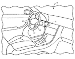
ハンドルは、いくつかの区域に分けられ得る。例えば、ハンドルは、以下の図1の例に示されるように、4つのスポーク設計を有し得、これは、上部リム部、下部リム部、左手部、及び右手部という4つの区域を含む。運転者の手の片手または両手でハンドルを握る運転などにより、これらの区域のうちの1つ以上においてハンドルリム上で圧力が検出されるとき、接点が特定され得る。車両設定を用いて、最小数の接点が安全運転状態を確立するために予め設定され得る。 The handle can be divided into several areas. For example, the handle may have four spoke designs, as shown in the example of FIG. 1 below, which includes four areas: an upper rim portion, a lower rim portion, a left hand portion, and a right hand portion. A contact may be identified when pressure is detected on the handle rim in one or more of these areas, such as by driving the handle with one or both hands of the driver's hand. Using vehicle settings, a minimum number of contacts can be preset to establish a safe driving condition.
本明細書に記載される特徴は、手検出システムの一部であり得、これは、ハンドルと、1つ以上の感圧センサと、制御ユニットとを含み得る。制御ユニットは、感圧センサから信号を受信すること、メッセージによって記録もしくは送信される情報を出力すること、及び/または加熱デバイス等のデバイスにコマンドを提供することなど、本明細書に記載されるステップ及び特徴を実施するように構成またはプログラムされ得る。制御ユニットは、例えば、不揮発性メモリが本明細書に記載されるステップ及び特徴に対してプログラミングすることを含むCPUであり得る。 The features described herein can be part of a hand detection system, which can include a handle, one or more pressure sensitive sensors, and a control unit. The control unit is described herein, such as receiving a signal from a pressure sensitive sensor, outputting information recorded or transmitted by a message, and / or providing a command to a device such as a heating device. It may be configured or programmed to implement steps and features. The control unit can be, for example, a CPU that includes non-volatile memory programming for the steps and features described herein.
例えば、経験豊富なベテラン運転者が、1つの接点のみを要求するように制御システムまたはユニットを設定し得る一方で、電子デバイスに誘惑されやすい可能性のある若者の親、経験の浅い運転者は、各々の手の接点に対応するハンドルの左手側及び右手側上の接点等の2つの接点を要求するようにシステムを設定し得る。 For example, an experienced veteran driver can set up a control system or unit to require only one contact, while a younger parent, an inexperienced driver who may be easily tempted by electronic devices The system can be configured to require two contacts, such as contacts on the left hand side and right hand side of the handle, corresponding to each hand contact.
別の例では、ハンドル上の手の存在及び位置決めを決定するためのシステムは、加熱されたハンドルシステムとともに利用され得る。手の接点は、その手のみがあるハンドルを局所的に加熱するために使用され、これは、ハンドルリム全体を加熱するときよりも速い昇温を可能にし得る。そのようなシステムはまた、運転者の手によって握られているハンドルのそれらの領域のみを加熱することによってより効率的な加熱システムを提供する。 In another example, a system for determining the presence and positioning of a hand on a handle can be utilized with a heated handle system. The hand contacts are used to locally heat a handle that has only that hand, which may allow for faster heating than when heating the entire handle rim. Such a system also provides a more efficient heating system by heating only those areas of the handle that are gripped by the driver's hand.
加熱素子設計内の別個の加熱ループは、上述のように、ハンドルの4つの区域など、ハンドルの各検知区域に提供され得る。別個のループのすべては、温度が電子または二元金属加熱コントローラによって制御され得るように、加熱サーモスタット温度読み取り区域内を通過することができる。電子制御ユニットまたは回路は、加熱されたハンドルが作動されたかの入力に基づいて、かつ運転者の手が位置する場所に基づいて、運転者の手に接触した区域により高い優先度を与えることなどによって、様々な区域または加熱ループに電流を優先させる方法を決定することができる。加熱された領域または接触している加熱されたそれらの領域もしくは区域のみを優先させることによって、加熱可能な領域の量が減少され得、より速い昇温曲線または反応が、同じ全電流をより小さいヒーター回路に導くことによって実現され得、したがって、運転者の手が位置するそれらの区域でのハンドルの昇温速度を改善する。 A separate heating loop within the heating element design may be provided for each sensing area of the handle, such as the four areas of the handle, as described above. All of the separate loops can pass through a heating thermostat temperature reading area so that the temperature can be controlled by an electronic or dual metal heating controller. The electronic control unit or circuit may give higher priority to the area in contact with the driver's hand, based on the input whether the heated handle has been activated and where the driver's hand is located, etc. It is possible to determine how to prioritize the current in various zones or heating loops. By prioritizing only the heated areas or those heated areas or zones that are in contact, the amount of heatable area can be reduced, and a faster temperature rise curve or reaction reduces the same total current to less It can be realized by leading to a heater circuit, thus improving the heating rate of the steering wheel in those areas where the driver's hand is located.
図1は、ハンドル20を含む車両運転席の室内10の一例を示す。運転者は、ハンドル20を回転させて、車輪を切り、車両を運転するときに通常行われるように、所望の方向に車両を操縦することができる。ハンドル20はまた、運転者の至近距離に提供されるスイッチまたはボタン等の様々な制御を含み得る。そのような制御は、車載オーディオシステム用(音量、チューニング、モード等を制御するためなど)、車両照明用(天井の照明、ヘッドライトなど)、電話用、または走行制御等の他の制御用であり得る。オーディオシステム、環境システム、照明システム、または他のシステム等のシステムの制御はまた、車両のダッシュボードまたはセンターコンソール等の車両内のどこかに提供され得る。以下にさらに詳細に論じられる制御ユニットまたは処理システム52もまた、車両内に提供され得る。
FIG. 1 shows an example of a vehicle driver's
ハンドル20はまた、1つ以上のスポーク24で外側リングまたはリム26に接続された中央ハブ22を含み得る。ハブ22は、車両のステアリングコラムに連結され得る。運転者は、外側リム26を握ることによってハンドル20を切ることができる。ハンドル20は、図1の例に示されるように、4つのスポークのハンドルであってもよい。別の例では、ハンドル20は、図2A〜6Cの例に示されるように、3つのスポークのハンドルであってもよい。他の例では、ハンドル20は、異なる数または配置のスポークを有し得る。
The
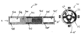
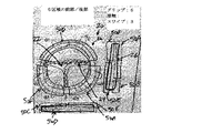
ここで図2A〜2Cを参照すると、例示的な手検出システムの正面図及びパターン図が示される。上記と同様に、ハンドル20は、1つ以上のスポーク24でリム26に接続された中央ハブ22を含む。図2Aに示されるように、手検出システムは、内側領域及び外側領域を有するハンドル20を含み得る。以下に詳細に論じられるように、ハンドル20は、オーバーモールド層、センサマット、ヒーターマット、外皮などを含むがこれらに限定されない1つ以上の層によって少なくとも部分的に包囲された電機子を含み得る。ハンドル20の断面は、図8の例に示されるように実質的に円形を画定することができる。ハンドル20の内側領域は任意に、中央ハブ22の方に実質的に向くリム26の一区分であり得る。例えば、ハンドル20の内側領域は任意に、ハンドル20を握るときに運転者の親指(複数可)と接触するリム26の区分を含み得る。ハンドル20の外側領域は任意に、中央ハブ22から実質的に外方に向くリム26の一区分であり得る。例えば、ハンドル20の外側領域は任意に、ハンドル20を握るときに運転者の指と接触するリム26の区分を含み得る。本開示は、内側領域及び外側領域が中央ハブ22の方に実質的に向くリム26の一区分、及び中央ハブ22から実質的に外方に向くリム26の一区分にそれぞれに限定されないことを企図する。例えば、内側領域は任意に、運転者から実質的に外方に向くリム26の一区分(すなわち、運転者に対してハンドルの裏面)であり得、外側領域は任意に、運転者の方に実質的に向くリム26の一区分(すなわち、運転者に対してハンドルの前部)であり得る。加えて、ハンドル20の内側領域及び外側領域は任意に、リム26の他の区分を占有し、およそ180度未満分離されたリム26の区分を含み得る。
Referring now to FIGS. 2A-2C, a front view and pattern diagram of an exemplary hand detection system is shown. Similar to the above, the
複数のセンサループ50A〜50Fを有するセンサマットは、ハンドル20に配置される。内側領域は、1つ以上のセンサループを含み得る。図2Aでは、内側領域は、例えば、センサループ50A〜50Bを含む。内側領域は任意に、リム26の「内側の」円周、例えば、中央ハブ22の方に実質的に向くリム26の一区分への近接であり得る。加えて、内側領域は任意に、運転者から外方に向くハンドル20の一部分への近接であり得る。外側領域は、1つ以上のセンサループを含み得る。図2Aでは、外側領域は、例えば、センサループ50C〜50Fを含む。外側領域は任意に、リム26の「外側の」円周、例えば、中央ハブ22から実質的に外方に向くリム26の一区分への近接であり得る。加えて、外側領域は任意に、運転者の方に向くハンドル20の一部分への近接であり得る。任意に、内側領域及び外側領域は、リム26の周囲に円周方向に配置され得る。例えば、内側領域及び外側領域は、およそ180度分離され得る。内側領域及び外側領域は、90度、120度、270度など、大体180度分離され得ることを理解されたい。
A sensor mat having a plurality of sensor loops 50 </ b> A to 50 </ b> F is disposed on the
センサループ50A〜50Fの各々は、検知区域を画定することができる。例えば、センサループ50Aは、検知区域5.1を画定することができる。センサループ50Bは、検知区域5.2を画定することができる。センサループ50Cは、検知区域1を画定することができる。センサループ50Dは、検知区域2を画定することができる。センサループ50Eは、検知区域3を画定することができる。センサループ50Fは、検知区域4を画定することができる。図2Aに示されるように、検知区域1と検知区域4との間のハンドル20上の合流点は、正面図及びパターン図において参照文字A−A’とラベル付けされる。加えて、図2Aのパターン図に示されるように、内側領域は、検知区域5が区域5.1と5.2とに二分される分割された区域構成で構成される。任意に、内側領域は、分割された区域構成で構成されることなく1つ以上のセンサループを含み得る。任意に、外側領域は、分割された区域構成で構成された1つ以上のセンサループを含み得る。
Each of the sensor loops 50A-50F can define a sensing area. For example, the sensor loop 50A can define a detection area 5.1. The sensor loop 50B can define a detection area 5.2. The sensor loop 50C can define a detection area 1. The sensor loop 50D can define the
ここで図2Bを参照すると、例えば、内側領域は、センサループ50A〜50Fを含み、外側領域は、センサループ50G〜50Jを含む。センサループ50A〜50Jの各々は、検知区域を画定することができる。センサループ50Aは、検知区域5.1を画定することができる。センサループ50Bは、検知区域5.2を画定することができる。センサループ50Cは、検知区域6.1を画定することができる。センサループ50Dは、検知区域6.2を画定することができる。センサループ50Eは、検知区域7.1を画定することができる。センサループ50Fは、検知区域7.2を画定することができる。センサループ50Gは、検知区域1を画定することができる。センサループ50Hは、検知区域2を画定することができる。センサループ50Iは、検知区域3を画定することができる。センサループ50Jは、検知区域4を画定することができる。図2Bに示されるように、検知区域1と検知区域4との間のハンドル20上の合流点は、正面図及びパターン図において参照文字A−A’とラベル付けされる。加えて、図2Bのパターン図に示されるように、内側領域は、検知区域5、6及び7が区域5.1と5.2と6.1と6.2と7.1と7.2とに二分される分割された区域構成で構成される。任意に、内側領域は、分割された区域構成で構成されることなく1つ以上のセンサループを含み得る。任意に、外側領域は、分割された区域構成で構成された1つ以上のセンサループを含み得る。
Referring now to FIG. 2B, for example, the inner region includes sensor loops 50A-50F and the outer region includes sensor loops 50G-50J. Each of the sensor loops 50A-50J can define a sensing area. The sensor loop 50A can define a detection area 5.1. The sensor loop 50B can define a detection area 5.2. The sensor loop 50C can define a detection area 6.1. The sensor loop 50D can define a detection area 6.2. The sensor loop 50E can define a detection area 7.1. The sensor loop 50F can define a sensing area 7.2. The sensor loop 50G can define the detection area 1. The sensor loop 50H can define the
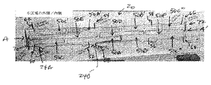
ここで図2Cを参照すると、例えば、内側領域は、センサループ50A〜50Jを含み、外側領域は、センサループ50K〜50Nを含む。センサループ50A〜50Nの各々は、検知区域を画定することができる。センサループ50Aは、検知区域5.1を画定することができる。センサループ50Bは、検知区域5.2を画定することができる。センサループ50Cは、検知区域5.3を画定することができる。センサループ50Dは、検知区域5.4を画定することができる。センサループ50Eは、検知区域6.1を画定することができる。センサループ50Fは、検知区域6.2を画定することができる。センサループ50Gは、検知区域7.1を画定することができる。センサループ50Hは、検知区域7.2を画定することができる。センサループ50Iは、検知区域8.1を画定することができる。センサループ50Jは、検知区域8.2を画定することができる。センサループ50Kは、検知区域1を画定することができる。センサループ50Lは、検知区域2を画定することができる。センサループ50Mは、検知区域3を画定することができる。センサループ50Nは、検知区域4を画定することができる。図2Cに示されるように、検知区域1と検知区域4との間のハンドル20上の合流点は、正面図及びパターン図において参照文字A−A’とラベル付けされる。加えて、図2Cのパターン図に示されるように、内側領域は、検知区域5、6、7及び8が区域5.1と5.2と5.3と5.4と6.1と6.2と7.1と7.2と8.1と8.2との間でそれぞれ分割される分割された区域構成で構成される。任意に、内側領域は、分割された区域構成で構成されることなく1つ以上のセンサループを含み得る。任意に、外側領域は、分割された区域構成で構成された1つ以上のセンサループを含み得る。
Referring now to FIG. 2C, for example, the inner region includes sensor loops 50A-50J and the outer region includes sensor loops 50K-50N. Each of the sensor loops 50A-50N can define a sensing area. The sensor loop 50A can define a detection area 5.1. The sensor loop 50B can define a detection area 5.2. The sensor loop 50C may define a detection area 5.3. The sensor loop 50D can define a detection area 5.4. The sensor loop 50E can define a detection area 6.1. The sensor loop 50F can define a sensing area 6.2. The sensor loop 50G can define a detection area 7.1. The sensor loop 50H can define a detection area 7.2. The sensor loop 50I can define a detection area 8.1. The sensor loop 50J may define a detection area 8.2. The sensor loop 50K can define the detection area 1. The sensor loop 50L can define the
図2A〜2Cに示される手検出システムはまた、運転者の手(または肘、膝、頭部、前腕などの運転者の身体の他の部位)が検知区域のうちの1つ以上に対応するハンドル20の一部分を押しているときに検出するように構成された図1の例に示されるような制御ユニット52等の制御ユニットを含み得る。例えば、センサループの各々は、接触検知区域を画定することができ、制御ユニット52は、運転者の手が検知区域に接触しているときに検出するように構成され得る。制御ユニット52は任意に、運転者の手が接触検知区域を軽く叩くか、または握る(例えば、軽く叩くことと比較して長時間の接触)ときに検出するように構成され得る。例えば、図2Aでは、センサループ50A〜50Fの各々は、接触検知区域を画定することができる。あるいはまたは加えて、センサループのうちの1つ以上は、スワイプ検知区域を画定することができ、制御ユニット52は、運転者の手がスワイプ検知区域でスワイプジェスチャ(例えば、2つ以上の点の間の検知区域との連続接触)をするときに検出するように構成され得る。例えば、図2Aでは、センサループ50C〜50Fの各々は、スワイプ検知区域を画定することができる。あるいはまたは加えて、内側領域に配置されたセンサループと、外側領域に配置されたセンサループとの間の重なり合う部分が、グリップ検知区域を画定することができ、制御ユニット52は、運転者の手がグリップ検知区域を握る(例えば、重なり合うセンサループに少なくとも部分的に巻き付け、それと接触する)ときに検出するように構成され得る。例えば、図2Aでは、内側領域に配置されたセンサループ50A及び/または50Bは、グリップ検知領域を画定する外側領域でセンサループ50Cと少なくとも部分的に重なり合う。1つ以上の接触検知区域、1つ以上のスワイプ検知区域、及び/または1つ以上のグリップ検知区域からの出力は任意に、車両安全システム(例えば、手を置いた/放した状態の検出)、車両制御システム(例えば、オーディオ、照明、環境、車両制御など)、及びハンドル加熱システムによって使用され得る。
The hand detection system shown in FIGS. 2A-2C also allows the driver's hand (or other part of the driver's body, such as the elbow, knee, head, forearm) to correspond to one or more of the sensing areas. A control unit such as the control unit 52 as shown in the example of FIG. 1 may be included that is configured to detect when a portion of the
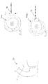
ここで図3A〜3Bを参照すると、例示的な2区域の手検出システムを図解する正面図、側面図、及び底面図が示される。2区域の手検出システムは、1つ以上のスポーク24でリム26に接続された中央ハブ22を有するハンドル20を含む。図3Aでは、ハンドル20は、内側領域に配置されたセンサループ50Aと、外側領域に配置されたセンサループ50Bとを含む複数のセンサループを有するセンサマットを含む。図3Bでは、ハンドル20は、前部領域に配置された(すなわち、運転者の方に向く)センサループ50Aと、後部領域に配置された(すなわち、運転者から外方に向く)センサループ50Bとを含む複数のセンサループを有するセンサマットを含む。センサループ50A、50Bの各々は、例えば、接触検知領域等の検知領域を画定する。あるいはまたは加えて、センサループ50A、50Bの重なり合う部分は、グリップ検知領域を画定する。任意に、上述のように、内側領域及び/または外側領域は、検知区域が複数のセンサループ(例えば、2つ、4つなどのセンサループ)を含む分割された区域構成で構成され得る。
Referring now to FIGS. 3A-3B, there are shown a front view, a side view, and a bottom view illustrating an exemplary two-zone hand detection system. The two-zone hand detection system includes a
ここで図3Cを参照すると、図3Aの2区域の手検出システムのパターン図が示される。ハンドル20は、内側領域に配置されたセンサループ50A、50A’(すなわち、分割された区域構成)と、外側領域に配置されたセンサループ50Bとを含む複数のセンサループを有するセンサマットを含む。ハンドル20上の合流点は、図3A及び3Cにおいて参照文字A−A’とラベル付けされる。図3Cに示されるように、センサループ50A、50A’、50Bの各々はさらに、電気信号を制御ユニット(例えば、制御ユニット52)に伝達するための導電性リード線52、54、56を含み得る。センサループ50A、50A’、50Bのうちの少なくとも1つに対する導電性リード線は任意に、任意の隣接したセンサループによって画定された検知区域のうちのいずれかの一部分に延在することなく経路指定され得る。これは、センサループ間のクロストーク量を最小限に抑える。例えば、導電性リード線52(すなわち、センサループ50Aの導電性リード線)は、センサループ50A’、50Bによって画定された検知区域のどの部分にも延在することなく経路指定される。任意に、導電性リード線52は、リム26からスポーク24のうちの1つがリム26と接続する領域24Aを通って経路指定される。任意に、センサループ50A、50A’、50Bの各々に対する導電性リード線52、54、56は任意に、任意の隣接したセンサループによって画定された検知区域のうちのいずれかの一部分に延在することなく経路指定され得る。
Referring now to FIG. 3C, a pattern diagram of the two-zone hand detection system of FIG. 3A is shown. The
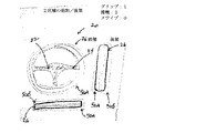
ここで図4A〜4Bを参照すると、例示的な3区域の手検出システムを図解する正面図、側面図、及び底面図が示される。3区域の手検出システムは、1つ以上のスポーク24でリム26に接続された中央ハブ22を有するハンドル20を含む。図4Aでは、ハンドル20は、内側領域に配置されたセンサループ50Aと、外側領域に配置されたセンサループ50B、50Cとを含む複数のセンサループを有するセンサマットを含む。外側領域に配置されたセンサループ50B、50Cは、離間されたパターンで配置される。図4Bでは、ハンドル20は、後部領域に配置されたセンサループ50Aと、前部領域に配置されたセンサループ50B、50Cとを含む複数のセンサループを有するセンサマットを含む。前部領域に配置されたセンサループ50B、50Cは、離間されたパターンで配置される。センサループ50A、50B、50Cの各々は、例えば、接触検知領域等の検知領域を画定する。あるいはまたは加えて、センサループ50A、50B、50Cのうちの1つ以上は、スワイプ検知領域を画定する。例えば、外側領域に配置されたセンサループ50B、50Cの各々は、スワイプ検知領域を画定することができる。あるいはまたは加えて、内側領域に配置されたセンサループ及び外側領域に配置されたセンサループの重なり合う部分は、グリップ検知領域を画定することができる。例えば、センサループ50A、50Bの重なり合う部分は、グリップ検知領域を画定する。任意に、上述のように、内側領域及び/または外側領域は、検知区域が複数のセンサループ(2つ、4つなどのセンサループ)を含む分割された区域構成で構成され得る。
4A-4B, there are shown a front view, a side view, and a bottom view illustrating an exemplary three-zone hand detection system. The three-zone hand detection system includes a
ここで図4Cを参照すると、図4Aの3区域の手検出システムのパターン図が示される。ハンドル20は、内側領域に配置されたセンサループ50A、50A’(すなわち、分割された区域構成)と、外側領域に配置されたセンサループ50B、50Cとを含む複数のセンサループを有するセンサマットを含む。ハンドル20上のセンサループ50Bとセンサループ50Cとの間の合流点は、図4A及び4Cにおいて参照文字A−A’とラベル付けされる。図4Cに示されるように、センサループ50A、50A’、50B、50Cの各々はさらに、電気信号を制御ユニット(例えば、制御ユニット52)に伝達するための導電性リード線52、54、56、58を含み得る。センサループ50A、50A’、50B、50Cのうちの少なくとも1つに対する導電性リード線は、任意の隣接したセンサループによって画定された検知区域のうちのいずれかの一部分に延在することなく経路指定され得る。これは、センサループ間のクロストーク量を最小限に抑える。例えば、導電性リード線52(すなわち、センサループ50Aの導電性リード線)は、センサループ50A’、50B、50Cによって画定された検知区域のどの部分にも延在することなく経路指定される。任意に、導電性リード線52は、リム26からスポーク24のうちの1つがリム26と接続する領域24Aを通って経路指定される。任意に、センサループ50A、50A’、50B、50Cの各々に対する導電性リード線52、54、56、58は任意に、任意の隣接したセンサループによって画定された検知区域のうちのいずれかの一部分に延在することなく経路指定され得る。
Referring now to FIG. 4C, a pattern diagram of the three-zone hand detection system of FIG. 4A is shown. The
ここで図5A〜5Bを参照すると、例示的な4区域の手検出システムを図解する正面図、側面図、及び底面図が示される。4区域の手検出システムは、1つ以上のスポーク24でリム26に接続された中央ハブ22を有するハンドル20を含む。図5Aでは、ハンドル20は、内側領域に配置されたセンサループ50A、50Bと、外側領域に配置されたセンサループ50C、50Dとを含む複数のセンサループを有するセンサマットを含む。内側領域に配置されたセンサループ50A、50B、及び外側領域に配置されたセンサループ50C、50Dは、離間されたパターンで配置される。任意に、外側領域に配置されたセンサループのうちの少なくとも1つ(例えば、センサループ50C)の中心点は任意に、内側領域に配置されたセンサループのうちの少なくとも2つ(例えば、センサループ50A、50B)の各々の中心点に対しておよそ90度以下で位置決めされ得る。図5Bでは、ハンドル20は、後部領域に配置されたセンサループ50A、50Bと、前部領域に配置されたセンサループ50C、50Dとを含む複数のセンサループを有するセンサマットを含む。後部領域に配置されたセンサループ50A、50B、及び前部領域に配置されたセンサループ50C、50Dは、離間されたパターンで配置される。任意に、前部領域に配置されたセンサループのうちの少なくとも1つ(例えば、センサループ50C)の中心点は任意に、後部領域に配置されたセンサループのうちの少なくとも2つ(例えば、センサループ50A、50B)の各々の中心点に対しておよそ90度以下で位置決めされ得る。センサループ50A、50B、50C、50Dの各々は、例えば、接触検知領域等の検知領域を画定する。あるいはまたは加えて、センサループ50A、50B、50C、50Dのうちの1つ以上は、スワイプ検知領域を含む。例えば、外側領域に配置されたセンサループ50C、50Dの各々は、スワイプ検知領域を画定することができる。あるいはまたは加えて、内側領域に配置されたセンサループ及び外側領域に配置されたセンサループの重なり合う部分は、グリップ検知領域を画定することができる。例えば、センサループ50A、50C、及びセンサループ50B、50Cの重なり合う部分は、グリップ検知領域をそれぞれ画定する。任意に、上述のように、内側領域及び/または外側領域は、検知区域が複数のセンサループ(例えば、2つ、4つなどのセンサループ)を含む分割された区域構成で構成され得る。
Referring now to FIGS. 5A-5B, there are shown a front view, a side view, and a bottom view illustrating an exemplary four-zone hand detection system. The four-zone hand detection system includes a
ここで図5Cを参照すると、図5Aの4区域の手検出システムのパターン図が示される。ハンドル20は、内側領域に配置されたセンサループ50A、50A’、50B、50B’、50B’’、50B’’’(すなわち、分割された区域構成)と、外側領域に配置されたセンサループ50C、50Dとを含む複数のセンサループを有するセンサマットを含む。ハンドル20上のセンサループ50Cとセンサループ50Dとの間の合流点は、図5A及び5Cにおいて参照文字A−A’とラベル付けされる。図5Cに示されるように、センサループ50A、50A’、50B、50B’、50B’’、50B’’’、50C、50Dの各々はさらに、電気信号を制御ユニット(例えば、制御ユニット52)に伝達するための導電性リード線52、54、56、58、60、62、64、66を含み得る。センサループ50A、50A’、50B、50B’、50B’’、50B’’’、50C、50Dのうちの少なくとも1つに対する導電性リード線は任意に、任意の隣接したセンサループによって画定された検知区域のうちのいずれかの一部分に延在することなく経路指定され得る。これは、センサループ間のクロストーク量を最小限に抑える。例えば、導電性リード線64(すなわち、センサループ50Cの導電性リード線)は、センサループ50A、50A’、50B、50B’、50B’’、50B’’’、50Dによって画定された検知区域のどの部分にも延在することなく経路指定される。導電性リード線64は、例えば、センサループ50A’、50B’等の内側領域に配置された少なくとも2つのセンサループ間の空間を通って経路指定される。任意に、導電性リード線64は、リム26からスポーク24のうちの1つがリム26と接続する領域24Aを通って経路指定される。任意に、センサループ50A、50A’、50B、50B’、50B’’、50B’’’、50C、50Dの各々に対する導電性リード線52、54、56、58、60、62、64、66は任意に、任意の隣接したセンサループによって画定された検知区域のうちのいずれかの一部分に延在することなく経路指定され得る。
Referring now to FIG. 5C, a pattern diagram of the four-zone hand detection system of FIG. 5A is shown. The
ここで図6A〜6Bを参照すると、例示的な6区域の手検出システムを図解する正面図、側面図、及び底面図が示される。6区域の手検出システムは、1つ以上のスポーク24でリム26に接続された中央ハブ22を有するハンドル20を含む。図6Aでは、ハンドル20は、内側領域に配置されたセンサループ50A、50B、50Cと、外側領域に配置されたセンサループ50D、50E、50Fとを含む複数のセンサループを有するセンサマットを含む。内側領域に配置されたセンサループ50A、50B、50C、及び外側領域に配置されたセンサループ50D、50E、50Fは、離間されたパターンで配置される。任意に、外側領域に配置されたセンサループのうちの少なくとも1つ(例えば、センサループ50D)の中心点は任意に、内側領域に配置されたセンサループのうちの少なくとも2つ(例えば、センサループ50A、50B)の各々の中心点に対しておよそ90度以下で位置決めされ得る。図6Bでは、ハンドル20は、後部領域に配置されたセンサループ50A、50B、50Cと、前部領域に配置されたセンサループ50D、50E、50Fとを含む複数のセンサループを有するセンサマットを含む。後部領域に配置されたセンサループ50A、50B、50C、及び前部領域に配置されたセンサループ50D、50E、50Fは、離間されたパターンで配置される。任意に、前部領域に配置されたセンサループのうちの少なくとも1つ(例えば、センサループ50D)の中心点は任意に、後部領域に配置されたセンサループのうちの少なくとも2つ(例えば、センサループ50A、50B)の各々の中心点に対しておよそ90度以下で位置決めされ得る。センサループ50A、50B、50C、50D、50E、50Fの各々は、例えば、接触検知領域等の検知領域を画定する。あるいはまたは加えて、センサループ50A、50B、50C、50D、50E、50Fのうちの1つ以上は、スワイプ検知領域を画定する。例えば、外側領域に配置されたセンサループ50D、50E、50Fの各々は、スワイプ検知領域を画定することができる。あるいはまたは加えて、内側領域に配置されたセンサループ及び外側領域に配置されたセンサループの重なり合う部分は、グリップ検知領域を画定することができる。例えば、センサループ50A、50D、及びセンサループ50B、50Dの重なり合う部分は、グリップ検知領域をそれぞれ画定する。任意に、上述のように、内側領域及び/または外側領域は、検知区域が複数のセンサループ(例えば、2つ、4つなどのセンサループ)を含む分割された区域構成で構成され得る。
Referring now to FIGS. 6A-6B, there are shown a front view, a side view, and a bottom view illustrating an exemplary six-zone hand detection system. The six-zone hand detection system includes a
ここで図6Cを参照すると、図6Aの6区域の手検出システムのパターン図が示される。ハンドル20は、内側領域に配置されたセンサループ50A、50A’、50B、50B’、50C、50C’、50C’’、50C’’’(すなわち、分割された区域構成)と、外側領域に配置されたセンサループ50D、50E、50Fとを含む複数のセンサループを有するセンサマットを含む。ハンドル20上のセンサループ50Eとセンサループ50Fとの間の合流点は、図6A及び6Cにおいて参照文字A−A’とラベル付けされる。図6Cに示されるように、センサループ50A、50A’、50B、50B’、50C、50C’、50C’’、50C’’’、50D、50E、50Fの各々はさらに、電気信号を制御ユニット(例えば、制御ユニット52)に伝達するための導電性リード線52、54、56、58、60、62、64、66、68、70、72を含み得る。センサループ50A、50A’、50B、50B’、50C、50C’、50C’’、50C’’’、50D、50E、50Fのうちの少なくとも1つに対する導電性リード線は、任意の隣接したセンサループによって画定された検知区域のうちのいずれかの一部分に延在することなく経路指定され得る。これは、センサループ間のクロストーク量を最小限に抑える。例えば、導電性リード線70(すなわち、センサループ50Eの導電性リード線)は、センサループ50A、50A’、50B、50B’、50C、50C’、50C’’、50C’’’、50D、50Fによって画定された検知区域のどの部分にも延在することなく経路指定される。導電性リード線70は、例えば、センサループ50C、50C’’等の内側領域に配置された少なくとも2つのセンサループ間の空間を通って経路指定される。任意に、導電性リード線70は、リム26からスポーク24のうちの1つがリム26と接続する領域24Aを通って経路指定される。任意に、センサループ50A、50A’、50B、50B’、50C、50C’、50C’’、50C’’’、50D、50E、50Fの各々に対する導電性リード線52、54、56、58、60、62、64、66、68、70、72は任意に、任意の隣接したセンサループによって画定された検知区域のうちのいずれかの一部分に延在することなく経路指定され得る。任意に、センサループ50A、50A’、50B、50B’、50C、50C’、50C’’、50C’’’、50D、50E、50Fのうちの少なくとも1つに対する導電性リード線は、隣接したセンサループによって画定された検知区域の一部分を通って経路指定され得る。例えば、電性リード線68(すなわち、センサループ50Dに対する導電性リード線)は、センサループ50Aによって画定された検知区域の一部分を通って経路指定される。任意に、センサループ50Aによって画定された検知区域を通って経路指定される導電性リード線68の少なくとも一区分は遮蔽される(例えば、導電性リード線の上に遮蔽層を提供することによる)。これは、導電性リード線が隣接したセンサループによって画定された検知区域を通って経路指定されるときにセンサループ間のクロストーク量を最小限に抑える。任意に、導電性リード線68は、リム26からスポーク24のうちの1つがリム26と接続する領域24Bを通って経路指定される。
Referring now to FIG. 6C, a pattern diagram of the six-zone hand detection system of FIG. 6A is shown. The
図2A〜6Cの例に示される手検出システムは、単に例として提供される。本開示は、図示されるもの以外の手検出システムが本開示の教示に従って提供され得ることを企図する。例えば、5区域、7区域、8区域、9区域、10区域などの手検出システムは、複数のセンサループを用いて設計され得る。 The hand detection system shown in the example of FIGS. 2A-6C is provided merely as an example. The present disclosure contemplates that hand detection systems other than those shown may be provided in accordance with the teachings of the present disclosure. For example, hand detection systems such as 5, 7, 8, 9, 10, 10 can be designed with multiple sensor loops.
上述のように、図2A〜6Cに関して論じられるハンドル20は、複数のセンサループ50を有するセンサマットを含む。そのようなセンサマットは、図8に関して論じられるように、例えば、電機子40(または本体)と外皮42との間に提供される感圧材料であり得る。そのような圧力センサマットは、センサループ50の各々に近接したハンドル20の領域を握る手によって引き起こされた圧力を検知するように構成され得る。例えば、ハンドル20は、ハンドル20の周縁部を中心として外側リム26上に配置された4つのセンサループ50を含み得る。他の実施形態では、ハンドル20は、おおよその数の区域及びおおよそ数のセンサループ50を含み得る。センサループ50の数を増加させることにより、ハンドル20上の運転者の手の位置が検知され得る精度を高めることができる。センサループ50は、ハンドル20の外側リム26上に位置していると図に示されるが、他の実施形態では、運転者の手の位置をさらにより正確に検知するために、そのようなセンサは、スポーク24上、またはハブ22上など、他の位置で外皮42の下で提供され得る。
As described above, the
そのような圧力センサは、2011年3月30日に出願された米国特許出願第13/076,226号に記載され、これは、その全体が参照により本明細書に組み込まれる。米国特許出願第13/076,226号に論じられるように、そのような圧力センサは、概して対称な層状関係で構成された担体材料のシート、導体、電極、及び感圧材料を含み得る(例えば、感圧材料の両側に配設された担体シート、導体、及び電極)。担体シート、導体、電極、及び感圧材料は、動的衝撃事象中に予期された力に従ってセンサの導電または電気特性を変化させるように選択的に構成され得る。 Such a pressure sensor is described in US patent application Ser. No. 13 / 076,226, filed Mar. 30, 2011, which is hereby incorporated by reference in its entirety. As discussed in US patent application Ser. No. 13 / 076,226, such a pressure sensor may include a sheet of carrier material, a conductor, an electrode, and a pressure sensitive material configured in a generally symmetrical layered relationship (eg, , Carrier sheets, conductors, and electrodes disposed on both sides of the pressure sensitive material). The carrier sheet, conductor, electrode, and pressure sensitive material can be selectively configured to change the conductive or electrical properties of the sensor according to the expected force during a dynamic impact event.
米国特許出願第13/076,226号に論じられるように、そのような感圧材料は、それに作用する力または圧力に反応して抵抗または導電/電気特性を変化させるように構成され得る。より具体的には、感圧材料は、力または圧力が存在しないときに絶縁体として実質的に機能することができ、より多くの力または圧力が存在するときに抵抗が減少する。低い力と高い力との間で、感圧材料は、予測可能な様式で力または圧力に反応し、増加する力で抵抗が減少する。感圧材料は、例えば、カーボンナノチューブ導電性ポリマーであってもよい。感圧材料は、二次元もしくは三次元インクジェットまたはスクリーン印刷、蒸着、または従来のプリント回路技術、そのようなエッチング、写真製版、もしくはフライス加工等の印刷プロセスによって電極のうちの1つに適用され得る。グラフィーム(grapheme)またはグラフィーム導電性ポリマーの材料の粒径など、より小さい粒径を有する感圧材料が使用されるとき、感圧材料はまた、蒸着等の従来のプリント回路技術によって適用され得る。他の例示的な実施形態によれば、感圧材料は、銀または銅等の導体でドープしたシリセン(silicene)ポリマー材料であってもよい。他の例によれば、感圧材料は、量子トンネル複合材(QTC)であり得、これは、ファウラーノルドハイムトンネリングを利用する可変抵抗感圧材料である。QTCは、Brompton−on−Swale,UKのPeratech(www.peratech.com)によって商業的に作製された材料である。センサ内のQTC材料は、導電性粒子が離れ過ぎているので伝導することができないため、ゼロの圧力またはゼロの力が加えられるときに絶縁体として機能し得るが、圧力(または力)が加えられるとき、導電性粒子は、電子がセンサの抵抗を変化させる絶縁層を変化させる絶縁層を通過することができるように、他の導電性粒子により近づく。したがって、センサ内のQTCの抵抗は、センサに作用する力または圧力の関数である。 As discussed in US patent application Ser. No. 13 / 076,226, such pressure sensitive materials may be configured to change resistance or conductive / electrical properties in response to forces or pressures acting on it. More specifically, the pressure sensitive material can function substantially as an insulator when no force or pressure is present, and the resistance decreases when more force or pressure is present. Between low and high forces, the pressure sensitive material responds to the force or pressure in a predictable manner and the resistance decreases with increasing force. The pressure sensitive material may be, for example, a carbon nanotube conductive polymer. The pressure sensitive material can be applied to one of the electrodes by a printing process such as two-dimensional or three-dimensional ink jet or screen printing, vapor deposition, or conventional printed circuit technology, such etching, photoengraving, or milling. . When pressure sensitive materials with smaller particle sizes are used, such as grapheme or graphitic conductive polymer material, pressure sensitive materials are also applied by conventional printed circuit techniques such as vapor deposition. obtain. According to another exemplary embodiment, the pressure sensitive material may be a silicene polymer material doped with a conductor such as silver or copper. According to another example, the pressure sensitive material can be a quantum tunnel composite (QTC), which is a variable resistance pressure sensitive material that utilizes Fowler-Nordheim tunneling. QTC is a material made commercially by Peratech (www.peratech.com) of Brompton-on-Swale, UK. The QTC material in the sensor can function as an insulator when zero pressure or zero force is applied because the conductive particles are too far away to conduct, but pressure (or force) is applied. When done, the conductive particles get closer to other conductive particles so that electrons can pass through the insulating layer changing the insulating layer changing the resistance of the sensor. Thus, the resistance of the QTC in the sensor is a function of the force or pressure acting on the sensor.
感圧材料は、それが外皮42の下に隠され得るため、ハンドル20上の手の位置を決定し、それ故に外皮42の審美的または人間工学的機能を妨げないセンサマットとして望ましい可能性がある。さらに、圧力センサマットは、運転者の手が静電容量センサ等の別の種類のセンサを妨げ得る手袋等の衣類で覆われる場合であっても、ハンドル20上の手の存在を検知することができる。
A pressure sensitive material may be desirable as a sensor mat that determines the position of the hand on the
外皮42は、外側リム26に内向きの力を付与する比較的引き締まったフィルムまたは材料であり得る。外皮42の張力によって引き起こされたこの初期の力は相殺され得、システムは、この力を無視し、かつ運転者の手によって引き起こされた圧力のみを検知するように較正されるか、またはゼロに設定され得る。 The skin 42 may be a relatively tight film or material that imparts an inward force to the outer rim 26. This initial force caused by the tension of the skin 42 can be offset, and the system can be calibrated to ignore this force and detect only the pressure caused by the driver's hand, or zero. Can be set.
ハンドル上の運転者の手の存在及び位置を決定することは、運転の癖を監視し、かつ運転者にフィードバックまたは警告を与えるために使用され得る。センサマットは、図1の例に示されるように、制御ユニットまたは処理システム52に連結されてもよく、これは、センサループ50からデータを受信し、他の視覚、音声、もしくは他の機能性信号、またはフィードバック機構を起動することができる。 Determining the presence and position of the driver's hand on the steering wheel can be used to monitor driving habits and provide feedback or warning to the driver. The sensor mat may be coupled to a control unit or processing system 52, as shown in the example of FIG. 1, which receives data from the sensor loop 50 and has other visual, audio, or other functionality. A signal or feedback mechanism can be activated.
図7の例に示されるように、加熱システム100は、リム26上に複数の加熱ループまたは区域102を含むヒーターマットを含み得る。各ループ102は、ハンドル20の検知区域(図2A〜6Cの例に示される検知区域など)のうちの1つに対応する。加熱ループ102の数及び配置は、検知区域の数及び配置よって異なり得る。別個のループ102の各々は、サーモスタット104に連結され得る。個々のループ102の温度は、車両の電気系統等の電源108から電力を引き出す加熱コントローラ106(電子または二元金属コントローラなど)によって制御され得る。コントローラ106は、電子回路または制御ユニットを使用して、加熱システム100の状態(例えば、電源がオンであるか、またはオフであるか)、及びセンサループ50によって決定されるにつれて、外側リム26上の運転者の手の位置に基づいてループ102に加える熱を決定することができる。
As shown in the example of FIG. 7, the heating system 100 may include a heater mat that includes a plurality of heating loops or
運転者の手の位置を決定することによって、加熱システム100は、運転者の手が位置するリム26の部分のみを昇温するか、または近くのそれらの部分を加熱し得る。加熱可能な領域の量を減少させることによって、より速い昇温曲線または反応が、同じ全電流をより小さいヒーター回路に導くことによって実現され得、したがって手が位置する区域でハンドルの昇温速度を改善する。 By determining the position of the driver's hand, the heating system 100 may heat up only those parts of the rim 26 where the driver's hand is located, or heat those parts nearby. By reducing the amount of heatable area, a faster ramp-up curve or reaction can be achieved by directing the same total current to a smaller heater circuit, thus increasing the handle ramp rate in the area where the hand is located. Improve.
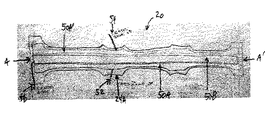
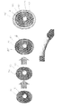
図8を参照すると、本明細書に論じられるハンドル20は、金属(例えば、鋼、マグネシウム、またはアルミニウムなど)等の比較的硬質材料、ポリマー、木材、または強化ポリマー(例えば、繊維強化ポリマー、粒子強化ポリマーなど)等の複合材から形成された電機子40を含み得る。そのような電機子40は、骨組み、外殻、基部の形態、または当該技術分野において使用される他の電機子の形態で提供され得る。電機子40は、ハンドル20に強度及び形状を提供することができる。電機子40が中空体である場合、これは、ポリウレタン発泡体または他の好適な材料等の消音材料で充填されてもよい。加えて、電機子40は、第1のオーバーモールド層80によって包囲されてもよく、これは、ポリマー、発泡体、木材等の外側リム26の本体を提供する。例えば、第1のオーバーモールド層80は任意に、ポリウレタン発泡体層であり得る。任意に、第1のオーバーモールド層80は、熱可塑性エラストマー発泡体であり得る。加えて、センサマット51は任意に、第1のオーバーモールド層80の少なくとも一部分の上に提供され得る。センサマット51は任意に、複数のセンサループ(例えば、センサループ50)を含むセンサマットであり得、各センサループは、図2A〜6Cの例において上述の検知区域を画定する。センサマット51は任意に、単一の検知区域を画定するセンサマットであり得る。加えて、第2のオーバーモールド層85は任意に、センサマット51の少なくとも一部分を包囲することができる。例えば、第2のオーバーモールド層85は任意に、ポリウレタン発泡体層であり得る。任意に、第2のオーバーモールド層85は、熱可塑性エラストマー発泡体であり得る。さらに、加熱マット101は任意に、第2のオーバーモールド層85の少なくとも一部分の上に提供され得る。加熱マット101は任意に、図7の例において上述の複数の加熱区域102を含む加熱マットであり得る。加熱マット101は任意に、単一の加熱区域を画定する加熱マットであり得る。第2のオーバーモールド層85は、センサマット51と加熱マット101との間で遮蔽する層を提供することができる。したがって、追加の遮蔽層(複数可)は、センサと加熱マットとの間に必要とされなくてもよく、これは、ハンドル20を製造する費用を減少させる。任意に、加熱マット101は、第1のオーバーモールド層80の少なくとも一部分の上に提供され得、センサマット51は、第2のオーバーモールド層85の少なくとも一部分の上に提供され得る。
Referring to FIG. 8, the
ここで図9Aを参照すると、複数のセンサ及び/またはヒーターマットの一部の平面図が示される。マットは、図2A〜8の例において論じられるセンサマットまたはヒーターマットであり得る。例えば、マット90Aは、実質的に矩形のマットの一部分を図解する。マット90Aの対向縁部92Aは、実質的に平行に延在する。加えて、マット90Aの検知または加熱区域95Aは、縁部92Aのうちの少なくとも1つから所定の量(例えば、空間94)で分離される。任意に、マット90Aの検知または加熱区域95Aは、縁部92Aのうちの少なくとも1つからおよそ5mm分離される。マット90Aの検知または加熱区域95Aは任意に、縁部92Aのうちの少なくとも1つから大体5mm分離され得ることを理解されたい。マット90Aがハンドルのリムの周囲に提供されるとき、空間94は、マット90Aの検知/加熱素子が配置されない「不感区域」を提供する。図9Bを参照すると、ハンドル20の一部分の線A−A’に沿って切り取られた断面図に不感区域96が示される。マット90Aは、不感区域96内で熱を検知または提供することができない。組み立て過程の間、ハンドル20のリムを覆う外皮は、マット90Aの検知または加熱区域95Aを損なうことなく不感区域96内にともに縫い合わせられ得る。
Referring now to FIG. 9A, a plan view of a portion of a plurality of sensors and / or heater mats is shown. The mat can be a sensor mat or a heater mat as discussed in the examples of FIGS. For example, mat 90A illustrates a portion of a substantially rectangular mat. The opposing edge 92A of the mat 90A extends substantially in parallel. In addition, the sensing or heating area 95A of the mat 90A is separated from at least one of the edges 92A by a predetermined amount (eg, space 94). Optionally, mat 90A sensing or heating zone 95A is separated from at least one of edges 92A by approximately 5 mm. It should be understood that the sensing or heating area 95A of the mat 90A can optionally be separated by approximately 5 mm from at least one of the edges 92A. When the mat 90A is provided around the rim of the handle, the space 94 provides a “dead zone” where the sensing / heating elements of the mat 90A are not located. Referring to FIG. 9B, a dead zone 96 is shown in a cross-sectional view taken along line A-A ′ of a portion of the
マット90B及び90Cは、連結及び/または交互配置領域を有するマットの一部を図解する。マット90Aと同様に、マット90B、90Cは、図2A〜8の例において論じられるセンサマットまたはヒーターマットであり得る。マット90B、90Cは、検知または加熱区域95B、95Cをそれぞれ有する。マット90Bは、鋸歯パターンを画定する対向縁部92Bを含む。例えば、マット90Bは、対応する突出部97Aと、切欠部97Bとを有する。マット90Cは、城郭パターンを画定する対向縁部92Cを含む。例えば、マット90Cは、対応する突出部97Aと、切欠部97Bとを有する。本開示は、マットが鋸歯及び城郭パターン以外のパターンを画定する対向縁部を有し得ることを企図する。マット90B、90Cがハンドルのリムの周囲に提供されると、マットの突出部は、上述の不感区域に対応する連結領域内の検知または加熱能力に延在し、それを提供することができる。例えば、各対向縁部の突出部は交互に、連結領域に延在することができる。図9Bを参照すると、ハンドル20の一部分の線A−A’に沿って取られた断面図に連結領域98が示される。有し、連結するマット、及び/または交互配置領域を提供することによって、検知または加熱区域95B、95Cと縁部92B、92Cとの間の空間94を減少させることが可能である。
Mats 90B and 90C illustrate a portion of a mat having connected and / or interleaved regions. Similar to mat 90A, mats 90B, 90C can be sensor mats or heater mats as discussed in the examples of FIGS. The mats 90B and 90C have sensing or heating areas 95B and 95C, respectively. The mat 90B includes opposing edges 92B that define a sawtooth pattern. For example, the mat 90B has a corresponding protrusion 97A and a notch 97B. The mat 90C includes opposed edges 92C that define a castle pattern. For example, the mat 90C has a corresponding protrusion 97A and a notch 97B. The present disclosure contemplates that the mat may have opposing edges that define patterns other than sawtooth and castle patterns. When mats 90B, 90C are provided around the rim of the handle, the mat protrusions can extend and provide a sensing or heating capability in the coupling area corresponding to the dead zone described above. For example, the protrusions at each opposing edge can alternately extend into the connection region. Referring to FIG. 9B, the coupling region 98 is shown in a cross-sectional view taken along line A-A ′ of a portion of the
電機子40は、電機子40を少なくとも部分的に覆う被覆または外皮42で覆われ得る。外皮42は任意に、1つ以上のセンサマット50及び1つ以上の加熱マット102の上に提供され得る。1つ以上のセンサマット50及び1つ以上の加熱マット102が第2のオーバーモールド層85によって分離されるため、外皮42をセンサマット50及び加熱マット102の上に適合することに関する巻き付けの品質及び過程関連の懸念が取り除かれる。外皮42は、ハンドル20に審美的に魅力的な外観を提供するように構成され得る。外皮42はまた、運転者の快適さを改善するためにハンドル20の外側に人間工学的に魅力的な層を追加するように構成され得る。一例によれば、外皮42は、射出成形ポリウレタン材料から形成され得る。他の例によれば、外皮42は、オレフィン熱可塑性エラストマー(TEO)、熱可塑性オレフィン(TPO)、熱可塑性エラストマー発泡体、ゴム、または任意の他の好適な材料等の多種多様な他の成形材料から形成され得る。他の例によれば、外皮42は、革、織物、ポリマー材料など、電機子の周囲に巻き付けられるフィルムまたはシートであり得る。他の例によれば、外皮42は、木材、炭素繊維複合材など、概して硬質材料から形成された積層体の外殻であり得る。発泡体等の下地材料は、運転者の人間工学的な快適さをさらに高めるために外皮42の下に提供され得る。ハンドル20はさらに、材料(革または木材)、別個の裏蓋、スイッチ、ベゼル等から形成されたアップリケなど、それに連結された構成要素を有し得る。
The armature 40 may be covered with a covering or skin 42 that at least partially covers the armature 40. An outer skin 42 may optionally be provided on one or more sensor mats 50 and one or
本システムは、感圧材料を使用して、ハンドル上のもう1つ2つの手の接触を測定すると上に記載されるが、他の実施形態では、異なる検知手段が使用されてもよい。例えば、ハンドル上の手の存在及び位置決めは、上述のように、静電容量または抵抗ベースのセンサで検出され得る。 While the system is described above using pressure sensitive material to measure the contact of two more hands on the handle, in other embodiments, different sensing means may be used. For example, the presence and positioning of the hand on the handle can be detected with a capacitance or resistance based sensor, as described above.
センサマット50は、処理システム52に二値信号(例えば、手を置いているか、または手を放したか)を提供するように構成されてもよく、またはハンドル20に加えられた圧力の量、ハンドル上の圧力の変化率などを説明する処理システム52にアナログ信号を提供することができてもよい。センサマット50がアナログ信号を提供する場合、処理システム52は、例えば、ハンドル上の圧力がゆっくりと低下したことを示す信号と比較して、ハンドル上の圧力が迅速に低下したことを示す信号と異なって反応するように構成されてもよい。接点のうちの1つで迅速に低下する圧力は、手が意図的な動作(例えば、携帯電話に応答する動作、ラジオ局を変更する動作、ギアを入れ替える動作など)でハンドル20から比較的迅速に外れたことを示すと解釈されてもよい。一方、複数の接点でゆっくりと低下する圧力は、手がゆっくりとハンドルから外れたことを示すと解釈されてもよく、これは、眠そうな運転者、酔った運転者、医学的発症に苦しむ運転者によるものであり得る。処理システム52は次、経過時間が所定の限界を超える場合、手がハンドルから外れた速度に基づいて異なる警告応答を開始するように構成されてもよい。
The sensor mat 50 may be configured to provide a binary signal to the processing system 52 (eg, whether the hand is placed or released), or the amount of pressure applied to the
本明細書で利用されるとき、用語「およそ」、「約」、「実質的に」、及び類似の用語は、本開示の主題が属する当業者による一般的かつ許容された使用と調和して広い意味を有することを意図する。これらの用語は、これらの特徴の範囲を提供される正確な数値範囲に限定することなく記載され、特許請求されるある特定の特徴の説明が可能になることを意図することが本開示を再検討する当業者によって理解されるべきである。したがって、これらの用語は、記載され、特許請求される主題の実体がない、または重要ではない修正もしくは変形が添付の特許請求の範囲に列挙されるように本発明の範囲内であると考慮されることを示すと解釈されるべきである。 As used herein, the terms “approximately”, “about”, “substantially”, and similar terms are in harmony with common and permissible uses by those of ordinary skill in the art to which the subject matter of the present disclosure belongs. It is intended to have a broad meaning. These terms are described without limiting the scope of these features to the exact numerical range provided, and the disclosure is intended to allow for the description of certain claimed features. It should be understood by one of ordinary skill in the art to consider. Accordingly, these terms are considered to be within the scope of the present invention as described in the appended claims, with no ambitious or unimportant modifications or variations of the claimed subject matter. Should be interpreted to show that
様々な実施形態を説明するために本明細書で使用されるとき、用語「例示的な(exemplary)」は、そのような実施形態が考えられる実施形態の考えられる実施例、表現、及び/または図解であることを示すことを意図する(かつそのような実施形態が必然的に並外れたまたは最高の実施例であることをそのような用語が内包することを意図しない)ことに留意されるべきである。 As used herein to describe various embodiments, the term “exemplary” may refer to possible examples, representations, and / or representations of embodiments in which such embodiments are contemplated. It should be noted that it is intended to be illustrative (and such terms are not intended to be inclusive of such embodiments necessarily being extraordinary or best examples). It is.
本明細書で使用されるとき、用語「連結された(coupled)」、「接続された(connected)」などは、2つの部材を互いに直接または間接的に接合することを意味する。そのような接合は、定常的(例えば、永久的)または可動(例えば、取り外し可能または剥離可能)であってもよい。そのような接合は、互いに単体として一体に形成された2つの部材、もしくは2つの部材及び任意の追加の中間部材で、または互いに取り付けられる2つの部材、もしくは2つの部材及び任意の追加の中間部材で実現されてもよい。 As used herein, the terms “coupled”, “connected” and the like mean that two members are joined directly or indirectly to each other. Such a bond may be stationary (eg, permanent) or movable (eg, removable or peelable). Such a joint is made of two members integrally formed as a single unit, or two members and any additional intermediate members, or two members attached to each other, or two members and any additional intermediate members. It may be realized with.
要素の位置(例えば、「最上部」、「底部」、「上」、「下」など)への本明細書での言及は単に、図における様々な要素の配向を説明するために使用される。様々な要素の配向は、他の例示的な実施形態によって異なってもよく、そのような変形は、本開示によって包含されることを意図することに留意されるべきである。 References herein to element positions (eg, “top”, “bottom”, “top”, “bottom”, etc.) are merely used to describe the orientation of the various elements in the figures. . It should be noted that the orientation of the various elements may vary with other exemplary embodiments, and such variations are intended to be encompassed by the present disclosure.
様々な例示的な実施形態に示されるようなハンドルに対する圧力検知システムの構築及び配置が単に例示であることに留意することが重要である。数少ない実施形態が本開示に詳細に記載されたが、本開示を再検討する当業者であれば、本明細書に記載される主題の新規教示及び利点から著しく逸脱することなく、多くの修正(例えば、様々な要素、パラメータの値、取り付け配置、材料の使用、色、配向などの大きさ、寸法、構造、形状、及び割合の変化)が可能であることを容易に理解するであろう。例えば、一体に形成されるように示される要素は、複数の部分または要素から構築されてもよく、要素の位置は反転されるか、そうでなければ変更されてもよく、個別の要素または位置の性質または数は変更されるか、または異なってもよい。任意の過程または方法のステップの順または順序は、代替的実施形態に従って変更または再順序付けされてもよい。他の置き換え、修正、変更、及び省略はまた、本実施形態の範囲から逸脱することなく、様々な例示的な実施形態の設計、動作状態、及び配置で行われてもよい。 It is important to note that the construction and placement of a pressure sensing system relative to the handle as shown in various exemplary embodiments is merely exemplary. Although a few embodiments have been described in detail in this disclosure, those skilled in the art reviewing this disclosure will be able to make many modifications without significantly departing from the novel teachings and advantages of the subject matter described herein. It will be readily appreciated that, for example, various elements, parameter values, mounting arrangements, material usage, color, orientation, etc., changes in size, dimensions, structure, shape, and proportions are possible. For example, an element shown to be formed in one piece may be constructed from multiple parts or elements, and the position of the elements may be reversed or otherwise changed, and individual elements or positions The nature or number of may vary or be different. The order or order of the steps of any process or method may be changed or reordered according to alternative embodiments. Other substitutions, modifications, changes, and omissions may also be made in the design, operating conditions, and arrangement of the various exemplary embodiments without departing from the scope of the embodiments.
本主題は、構造的特徴及び/または方法論的行為に特定の言語で記載されたが、添付の特許請求の範囲で定義される主題は、上述の特定の特徴または行為に必ずしも限定されないことを理解されるべきである。それよりむしろ、上述の特定の特徴及び行為は、特許請求の範囲を実装する例示的な形態として開示される。
Although the present subject matter has been described in certain language in structural features and / or methodological acts, it is understood that the subject matter defined in the appended claims is not necessarily limited to the particular features or acts described above. It should be. Rather, the specific features and acts described above are disclosed as example forms of implementing the claims.
Claims (42)
前記ハンドルに配置された複数のセンサループを含むセンサマットであって、前記センサマットの各々が検知区域を画定する、センサマットと、
前記検知区域のうちの1つ以上に対応する前記ハンドルの一部分を押す運転者の手を検出するように構成された制御ユニットであって、前記センサループのうちの1つ以上が、前記ハンドルの前記内側領域及び前記外側領域の各々に配置される、制御ユニットと、を備える、手検出システム。 A handle having an inner region and an outer region;
A sensor mat including a plurality of sensor loops disposed on the handle, wherein each of the sensor mats defines a sensing area;
A control unit configured to detect a driver's hand pushing a portion of the handle corresponding to one or more of the sensing zones, wherein one or more of the sensor loops And a control unit disposed in each of the inner region and the outer region.
車両のステアリングコラムへの接続のためのハブと、
前記ハブの周囲に延在するリムであって、前記内側領域及び前記外側領域を有する、リムと、
前記ハブと前記リムを接続する複数のスポークであって、前記センサループのうちの前記少なくとも1つに対する前記導電性リード線は、前記リムから前記スポークのうちの1つが前記リムと接続する領域を通って経路指定される、複数のスポークと、をさらに備える、請求項17に記載の手検出システム。 The handle is
A hub for connection to the steering column of the vehicle;
A rim extending around the hub, the rim having the inner region and the outer region;
A plurality of spokes connecting the hub and the rim, wherein the conductive lead to the at least one of the sensor loops is a region where one of the spokes from the rim connects to the rim. The hand detection system of claim 17, further comprising a plurality of spokes routed through.
車両のステアリングコラムへの接続のためのハブと、
前記ハブの周囲に延在するリムであって、前記内側領域及び前記外側領域を有する、リムと、
前記ハブと前記リムを接続する複数のスポークであって、前記センサループのうちの前記少なくとも1つに対する前記導電性リード線は、前記リムから前記スポークのうちの1つが前記リムと接続する領域を通って経路指定される、複数のスポークと、をさらに備える、請求項20に記載の手検出システム。 The handle is
A hub for connection to the steering column of the vehicle;
A rim extending around the hub, the rim having the inner region and the outer region;
A plurality of spokes connecting the hub and the rim, wherein the conductive lead to the at least one of the sensor loops is a region where one of the spokes from the rim connects to the rim. The hand detection system of claim 20, further comprising a plurality of spokes routed through.
前記ハンドルに配置された少なくとも1つのオーバーモールド層と、さらに備え、前記オーバーモールド層は、前記少なくとも1つのヒーターマットと前記センサマットとの間に配置される、請求項1に記載の手検出システム。 At least one heater mat disposed on the handle;
The hand detection system of claim 1, further comprising at least one overmold layer disposed on the handle, wherein the overmold layer is disposed between the at least one heater mat and the sensor mat. .
前記ハンドルのリムを画定する電機子と、
前記電機子の少なくとも一部分の周囲に配置された外皮であって、前記センサマットのうちの少なくとも1つ及び前記少なくとも1つのヒーターマットの上に配置される、外皮と、をさらに備える、請求項24に記載の手検出システム。 The handle is
An armature defining a rim of the handle;
25. A skin disposed around at least a portion of the armature, further comprising a skin disposed over at least one of the sensor mats and the at least one heater mat. The hand detection system described in.
前記ハンドルに配置された検知区域を画定するセンサマットと、
前記ハンドルに配置された加熱区域を画定するヒーターマットと、
前記ハンドルに配置されたオーバーモールド層であって、前記ヒーターマットと前記センサマットとの間に配置される、オーバーモールド層と、
前記検知区域に対応する前記ハンドルの一部分を押す運転者の手を検出するように構成された制御ユニットと、を備える、手検出システム。 A handle,
A sensor mat defining a detection area disposed on the handle;
A heater mat defining a heating zone disposed on the handle;
An overmold layer disposed on the handle, the overmold layer disposed between the heater mat and the sensor mat;
A control unit configured to detect a driver's hand pushing a portion of the handle corresponding to the sensing area.
前記ハンドルのリムを画定する電機子と、
前記電機子の少なくとも一部分の周囲に配置された外皮であって、前記センサマット及び前記ヒーターマットのうちの少なくとも一方の上に配置される、外皮と、をさらに備える、請求項36に記載の手検出システム。 The handle is
An armature defining a rim of the handle;
37. The hand of claim 36, further comprising: a skin disposed around at least a portion of the armature, wherein the skin is disposed on at least one of the sensor mat and the heater mat. Detection system.
前記ハンドルに配置された検知区域を画定するセンサマットと、
前記検知区域に対応する前記ハンドルの一部分を押す運転者の手を検出するように構成された制御ユニットと、を備え、前記センサマットは、交互の突出部及び切欠部を画定する対向縁部を有し、前記対向縁部の前記交互の突出部及び切欠部は、前記センサマットが前記ハンドルに配置されるときに交互配置領域を作成する、手検出システム。 A handle,
A sensor mat defining a detection area disposed on the handle;
A control unit configured to detect a driver's hand pushing a portion of the handle corresponding to the sensing area, wherein the sensor mat has opposing edges that define alternating protrusions and notches. And the alternating protrusions and notches of the opposing edge create an alternating area when the sensor mat is placed on the handle.
42. The hand detection system of claim 41, wherein the opposing edge defines at least one of a sawtooth pattern and a castle pattern.
Applications Claiming Priority (3)
| Application Number | Priority Date | Filing Date | Title |
|---|---|---|---|
| US201361764265P | 2013-02-13 | 2013-02-13 | |
| US61/764,265 | 2013-02-13 | ||
| PCT/US2014/016023 WO2014126999A1 (en) | 2013-02-13 | 2014-02-12 | Steering wheel hand detection systems |
Publications (2)
| Publication Number | Publication Date |
|---|---|
| JP2016508917A true JP2016508917A (en) | 2016-03-24 |
| JP6398994B2 JP6398994B2 (en) | 2018-10-03 |
Family
ID=51296492
Family Applications (1)
| Application Number | Title | Priority Date | Filing Date |
|---|---|---|---|
| JP2015557218A Active JP6398994B2 (en) | 2013-02-13 | 2014-02-12 | Handle hand detection system |
Country Status (5)
| Country | Link |
|---|---|
| US (1) | US9248851B2 (en) |
| JP (1) | JP6398994B2 (en) |
| CN (1) | CN105143015B (en) |
| DE (1) | DE112014000795T5 (en) |
| WO (1) | WO2014126999A1 (en) |
Cited By (3)
| Publication number | Priority date | Publication date | Assignee | Title |
|---|---|---|---|---|
| JP2020152365A (en) * | 2019-01-25 | 2020-09-24 | パナソニックIpマネジメント株式会社 | Steering heater |
| CN113396084A (en) * | 2019-01-31 | 2021-09-14 | 奥托立夫开发公司 | Detection device for vehicle steering wheel |
| JP7454651B2 (en) | 2019-08-23 | 2024-03-22 | オートリブ ディベロップメント エービー | vehicle steering wheel |
Families Citing this family (80)
| Publication number | Priority date | Publication date | Assignee | Title |
|---|---|---|---|---|
| US9292471B2 (en) | 2011-02-18 | 2016-03-22 | Honda Motor Co., Ltd. | Coordinated vehicle response system and method for driver behavior |
| US8698639B2 (en) | 2011-02-18 | 2014-04-15 | Honda Motor Co., Ltd. | System and method for responding to driver behavior |
| DE102011084903A1 (en) | 2011-10-20 | 2013-04-25 | TAKATA Aktiengesellschaft | Sensor systems for a motor vehicle |
| US11254209B2 (en) | 2013-03-15 | 2022-02-22 | Honda Motor Co., Ltd. | System and method for controlling vehicle systems in a vehicle |
| US10358034B2 (en) | 2016-03-30 | 2019-07-23 | Honda Motor Co., Ltd. | System and method for controlling a vehicle display in a moving vehicle |
| US9751534B2 (en) | 2013-03-15 | 2017-09-05 | Honda Motor Co., Ltd. | System and method for responding to driver state |
| US9475521B1 (en) | 2015-06-08 | 2016-10-25 | Honda Motor Co., Ltd. | Failsafe detection |
| US10499856B2 (en) | 2013-04-06 | 2019-12-10 | Honda Motor Co., Ltd. | System and method for biological signal processing with highly auto-correlated carrier sequences |
| GB2525840B (en) | 2014-02-18 | 2016-09-07 | Jaguar Land Rover Ltd | Autonomous driving system and method for same |
| DE102014007163B3 (en) * | 2014-05-15 | 2015-09-24 | Florian Gerber | Monitoring system for motor vehicles |
| JP6594963B2 (en) | 2014-05-22 | 2019-10-23 | ジョイソン セイフティ システムズ アクイジション エルエルシー | System and method for protecting a hand sensing system on a handle |
| CN111422238B (en) | 2014-06-02 | 2022-10-25 | Tk控股公司 | System and method for printing sensor circuit on sensor pad of steering wheel |
| DE102014218207A1 (en) * | 2014-09-11 | 2016-03-17 | Fraunhofer-Gesellschaft zur Förderung der angewandten Forschung e.V. | operating unit |
| CN104386046B (en) * | 2014-09-18 | 2018-03-20 | 李军廷 | A kind of brake method, device and automobile |
| DE102014223128A1 (en) | 2014-11-12 | 2016-05-12 | Bayerische Motoren Werke Ag | Steering wheel with a sensor structure for occupancy detection of a heated contact surface, steering wheel system and method for occupancy detection of a heated contact surface |
| FR3023519A1 (en) * | 2014-12-09 | 2016-01-15 | Continental Automotive France | SYSTEM FOR DETECTING THE PRESENCE AND POSITION OF HAND AND / OR FINGER ON A WHEEL |
| LU92732B1 (en) * | 2015-06-05 | 2016-12-06 | Iee Int Electronics & Eng Sa | Capacitive detection device and system for use in vehicle interior |
| DE102015211056A1 (en) * | 2015-06-16 | 2016-12-22 | Ford Global Technologies, Llc | Device for ventilating a steering wheel environment and method for operating the device |
| CN106240487B (en) | 2015-09-28 | 2018-11-20 | 北京智谷睿拓技术服务有限公司 | Exchange method, interactive device and mobile unit |
| FR3043381B1 (en) * | 2015-11-11 | 2018-04-27 | Autoliv Development Ab | WHEEL OF VEHICLE |
| CN107207028A (en) * | 2015-12-21 | 2017-09-26 | 深圳市柔宇科技有限公司 | Safe driving of vehicle control system |
| CN105711634A (en) * | 2016-01-27 | 2016-06-29 | 苏州寅初信息科技有限公司 | Steering wheel performing heating and cooling based on environment temperature |
| CN105691437A (en) * | 2016-01-27 | 2016-06-22 | 苏州寅初信息科技有限公司 | Steering wheel capable of heating or cooling hand body fitting surface |
| DE102016201406B4 (en) * | 2016-01-29 | 2020-03-26 | Joyson Safety Systems Germany Gmbh | Steering wheel for a motor vehicle |
| WO2017139313A1 (en) | 2016-02-09 | 2017-08-17 | Crown Equipment Corporation | Mounting bar assembly for a materials handling vehicle |
| FR3047718B1 (en) * | 2016-02-17 | 2019-07-12 | Autoliv Development Ab | WHEEL OF VEHICLE |
| DE102016204864A1 (en) | 2016-03-23 | 2017-09-28 | TAKATA Aktiengesellschaft | steering wheel assembly |
| US10336361B2 (en) | 2016-04-04 | 2019-07-02 | Joyson Safety Systems Acquisition Llc | Vehicle accessory control circuit |
| US10293783B2 (en) * | 2016-05-19 | 2019-05-21 | Ford Global Technologies, Llc | Driver detection steering wheel |
| US10043084B2 (en) * | 2016-05-27 | 2018-08-07 | Toyota Jidosha Kabushiki Kaisha | Hierarchical context-aware extremity detection |
| WO2018017835A1 (en) | 2016-07-20 | 2018-01-25 | Tk Holdings Inc. | Occupant detection and classification system |
| US20180093696A1 (en) * | 2016-09-30 | 2018-04-05 | Ford Global Technologies, Llc | Steering wheel assembly and heated steering wheel system |
| CN109923020B (en) * | 2016-10-28 | 2021-09-10 | 本田技研工业株式会社 | Steering wheel unit |
| DE102017111297A1 (en) | 2016-12-15 | 2018-06-21 | UC Universal Consulting GmbH | Method for producing a steering wheel with a sensor structure for single and multi-zone manual occupancy detection and a heatable contact surface |
| FR3062106A1 (en) * | 2017-01-23 | 2018-07-27 | Autoliv Development Ab | WHEEL OF VEHICLE |
| JP6655825B2 (en) * | 2017-03-13 | 2020-02-26 | パナソニックIpマネジメント株式会社 | Grip sensors, steering wheels and vehicles |
| IT201700048117A1 (en) * | 2017-05-04 | 2018-11-04 | Irca Spa | HEATING AND CAPACITIVE DETECTION DEVICE FOR THE WHEEL OF A VEHICLE |
| WO2018213344A1 (en) | 2017-05-15 | 2018-11-22 | Joyson Safety Systems Acquisition Llc | Systems and methods for heating and sensing proximity to vehicle components |
| US11211931B2 (en) | 2017-07-28 | 2021-12-28 | Joyson Safety Systems Acquisition Llc | Sensor mat providing shielding and heating |
| DE102017117610A1 (en) * | 2017-08-03 | 2019-02-07 | Trw Automotive Gmbh | A method of detecting hands of a driver on a steering wheel of a vehicle |
| FR3070635B1 (en) * | 2017-09-05 | 2019-08-23 | Continental Automotive France | OPTICAL TOUCH PALLET ON DRIVET WHEEL FOR FINGER DETECTION |
| LU100509B1 (en) * | 2017-11-03 | 2019-05-08 | Iee Sa | System for Hand Detection on a Steering Wheel |
| KR102534668B1 (en) * | 2018-01-05 | 2023-05-22 | 현대자동차주식회사 | Steering wheel |
| JP6998782B2 (en) * | 2018-02-06 | 2022-02-10 | 日本プラスト株式会社 | Covering member for handle, handle, and manufacturing method of handle |
| JP7055661B2 (en) * | 2018-02-22 | 2022-04-18 | 本田技研工業株式会社 | Vehicle control unit |
| JP6691568B2 (en) * | 2018-03-29 | 2020-04-28 | 株式会社Subaru | Driving support system |
| LU100755B1 (en) * | 2018-03-30 | 2019-10-01 | Iee Sa | Sensor Arrangement for Capacitive Position Detection of an Object |
| DE102018113879A1 (en) * | 2018-06-11 | 2019-12-12 | Trw Automotive Safety Systems Gmbh | Method for detecting a touch of a hand-operated steering device, in particular a vehicle steering wheel, and device for carrying out the method |
| CN108791058A (en) * | 2018-06-27 | 2018-11-13 | 梧州学院 | A kind of safe driving detection device and its control method based on steering wheel grip |
| DE102018217333A1 (en) * | 2018-10-10 | 2020-04-16 | Mahle International Gmbh | Steering device for a vehicle |
| US10807628B2 (en) * | 2018-11-16 | 2020-10-20 | Aisin Seiki Kabushiki Kaisha | Steering apparatus |
| LU101018B1 (en) * | 2018-11-27 | 2020-05-27 | Iee Sa | Sensor Arrangement for Capacitive Position Detection of a Hand on a Steering Wheel |
| WO2020195620A1 (en) * | 2019-03-25 | 2020-10-01 | アルプスアルパイン株式会社 | Sensor device and steering wheel |
| CN111753589B (en) * | 2019-03-28 | 2022-05-03 | 虹软科技股份有限公司 | Method and device for detecting state of hand-held steering wheel |
| CN110032227B (en) * | 2019-04-08 | 2021-03-30 | 北京小米移动软件有限公司 | Heating control method and device, heating equipment and machine-readable storage medium |
| CN109969248A (en) * | 2019-04-29 | 2019-07-05 | 延锋百利得(上海)汽车安全系统有限公司 | A kind of steering wheel for vehicle |
| US11001167B2 (en) | 2019-06-14 | 2021-05-11 | Joyson Safety Systems Acquisition Llc | Apparatus and method of producing a sensing substrate |
| US20220376691A1 (en) * | 2019-07-10 | 2022-11-24 | Iee International Electronics & Engineering S.A. | Device and method for detecting a hand grasp with a two-zone sensor in the steering wheel |
| LU101450B1 (en) * | 2019-10-18 | 2021-04-20 | Iee Sa | Device and Method for Detecting a Hand Grasp with a Two-Zone Sensor in the Steering Wheel |
| CN110356324A (en) * | 2019-08-20 | 2019-10-22 | 浙江泰康电子有限公司 | Vehicle steering wheel hand is from detection system |
| US20230036695A1 (en) * | 2019-09-04 | 2023-02-02 | Lg Electronics Inc. | Method for transmitting and receiving message in wireless communication system and vehicle therefor |
| CN110562313A (en) * | 2019-09-19 | 2019-12-13 | 安闻汽车技术(天津)有限公司 | heating device and steering wheel |
| FR3101597A1 (en) * | 2019-10-03 | 2021-04-09 | Autoliv Development Ab | Wiring supported by ribbon |
| DE202019106523U1 (en) | 2019-11-22 | 2019-12-17 | MöllerTech Engineering GmbH | Interior component, interior trim component and arrangement for a vehicle |
| DE102019134750B4 (en) * | 2019-12-17 | 2021-11-04 | Bayerische Motoren Werke Aktiengesellschaft | Steering wheel with two-hand touch detection |
| FR3115262B1 (en) * | 2020-10-16 | 2023-01-20 | Commissariat Energie Atomique | Multipoint contact detection device and method |
| US11130443B1 (en) | 2020-12-09 | 2021-09-28 | Autoliv Asp, Inc. | Light bar assemblies for a steering wheel |
| US11198387B1 (en) | 2020-12-09 | 2021-12-14 | Autoliv Asp, Inc. | Heat dissipation of a light bar assembly of a steering wheel |
| US11267499B1 (en) | 2020-12-09 | 2022-03-08 | Autoliv Asp, Inc. | Wrapping for a steering wheel |
| US11312294B1 (en) | 2020-12-10 | 2022-04-26 | Autolive Asp, Inc. | Light bar assemblies for a steering wheel |
| IL279430A (en) * | 2020-12-14 | 2022-07-01 | Krishevski Aharon | Vehicle reporting system |
| CN112706708B (en) * | 2021-01-15 | 2022-12-13 | 安闻汽车技术(天津)有限公司 | Sensor system for partitioned detection of inner shaft and outer shaft of steering wheel and steering wheel |
| JP2022134603A (en) * | 2021-03-03 | 2022-09-15 | 株式会社東海理化電機製作所 | Contact detection sensor and contact detection device |
| CN113386847A (en) * | 2021-04-30 | 2021-09-14 | 深圳市沃特沃德信息有限公司 | Warming method and device for vehicle handle and computer equipment |
| DE102022110982A1 (en) * | 2021-05-19 | 2022-11-24 | Toyoda Gosei Co., Ltd. | HANDLE |
| US11702138B2 (en) | 2021-05-24 | 2023-07-18 | Toyota Research Institute, Inc. | Method for lateral control assistance to enable one-handed driving of a vehicle |
| FR3124475A1 (en) | 2021-06-24 | 2022-12-30 | Autoliv Development Ab | Vehicle steering wheel with a rim comprising an electrical device |
| CN114212143B (en) * | 2021-12-20 | 2022-09-16 | 海安荣民汽车配件有限公司 | High energy-saving steering wheel hot-water bag of security |
| CN114148401B (en) * | 2021-12-31 | 2023-06-06 | 盐城同济汽车配件有限公司 | Automobile steering wheel skeleton with heating mechanism |
| JP2023105693A (en) * | 2022-01-19 | 2023-07-31 | 株式会社東海理化電機製作所 | steering |
Citations (9)
| Publication number | Priority date | Publication date | Assignee | Title |
|---|---|---|---|---|
| JPS61146670A (en) * | 1984-12-18 | 1986-07-04 | Daihatsu Motor Co Ltd | Hand warmer device for interior decoration parts for car |
| JPH03112772A (en) * | 1989-09-28 | 1991-05-14 | Nippon Plast Co Ltd | Steering wheel |
| JPH09226597A (en) * | 1996-02-20 | 1997-09-02 | Nippon Plast Co Ltd | Steering wheel |
| JP2000228126A (en) * | 1999-02-05 | 2000-08-15 | Matsushita Electric Ind Co Ltd | Steering input device |
| US6326593B1 (en) * | 1998-02-04 | 2001-12-04 | Takata-Petri Ag | Heating element for a part of an automobile which is held, especially the steering wheel |
| JP2006176037A (en) * | 2004-12-24 | 2006-07-06 | Aisin Seiki Co Ltd | Steering wheel cooling/heating device |
| WO2011016868A1 (en) * | 2009-08-06 | 2011-02-10 | North American Rescue, Llc | Direct application automotive steering wheel heater |
| JP2011219085A (en) * | 2010-04-02 | 2011-11-04 | Tk Holdings Inc | Steering wheel with hand pressure sensing |
| US20120326735A1 (en) * | 2011-06-22 | 2012-12-27 | Tk Holdings Inc. | Sensor system for steering wheel for vehicle |
Family Cites Families (25)
| Publication number | Priority date | Publication date | Assignee | Title |
|---|---|---|---|---|
| US3585626A (en) | 1967-06-13 | 1971-06-15 | Cesare Tartarini | Safety alarm device for drivers |
| JPS61146671A (en) | 1984-12-18 | 1986-07-04 | Daihatsu Motor Co Ltd | Hand warmer device for interior decoration parts for car |
| US6016103A (en) | 1997-09-25 | 2000-01-18 | Leavitt; Larry | Sleep-detecting driving gloves |
| US6172610B1 (en) | 1999-04-08 | 2001-01-09 | Robert S. Prus | Sleeping driver detector and alarm system |
| US6661345B1 (en) | 1999-10-22 | 2003-12-09 | The Johns Hopkins University | Alertness monitoring system |
| US7383283B2 (en) | 2001-10-16 | 2008-06-03 | Joseph Carrabis | Programable method and apparatus for real-time adaptation of presentations to individuals |
| JP3601511B2 (en) | 2001-12-18 | 2004-12-15 | トヨタ自動車株式会社 | Seat belt equipment |
| US6590499B1 (en) | 2002-02-04 | 2003-07-08 | D'agosto Joseph | Monitor alarm for detecting vehicle driver's sleepiness |
| US7830265B2 (en) | 2005-05-06 | 2010-11-09 | Jerome Arnold Power | Sleep alert device |
| CA2606612A1 (en) | 2005-05-06 | 2006-11-16 | Jerome Arnold Power | Sleep alert device |
| JP2007283932A (en) | 2006-04-18 | 2007-11-01 | Toyota Motor Corp | Occupant warming device for vehicle |
| JP2008059459A (en) | 2006-09-01 | 2008-03-13 | Toyota Motor Corp | Attention stirring system for vehicle |
| JP5347357B2 (en) | 2008-07-15 | 2013-11-20 | 新日鐵住金株式会社 | Awareness detection method and system, snooze driving prevention method and system, and program |
| US20100102972A1 (en) | 2008-10-29 | 2010-04-29 | Transportation Safety Products, Inc. | Driver inattention detection system and methodology |
| JP2011063103A (en) * | 2009-09-16 | 2011-03-31 | Denso Corp | Onboard equipment operation system |
| US20110257846A1 (en) * | 2009-11-13 | 2011-10-20 | William Bennett | Wheel watcher |
| US8405496B2 (en) * | 2009-11-13 | 2013-03-26 | William Bennett | Wheel watcher |
| US8564424B2 (en) * | 2009-12-07 | 2013-10-22 | Inventioneers Etc., Llc | Steering wheel hand position sensing device |
| US9007190B2 (en) * | 2010-03-31 | 2015-04-14 | Tk Holdings Inc. | Steering wheel sensors |
| US8547215B2 (en) * | 2010-11-24 | 2013-10-01 | Denso Corporation | Information presentation apparatus and system |
| US8738224B2 (en) | 2011-01-12 | 2014-05-27 | GM Global Technology Operations LLC | Steering wheel system |
| US20120232751A1 (en) | 2011-03-07 | 2012-09-13 | Jorge Guspan | Pressure-Sensitive Steering Wheel Controls |
| DE102011076174A1 (en) * | 2011-05-20 | 2012-11-22 | Robert Bosch Gmbh | Haptic steering wheel, steering wheel system and driver assistance system for a motor vehicle |
| CN102745231B (en) * | 2012-03-16 | 2014-05-14 | 浙江吉利汽车研究院有限公司 | Induction type warning system of automobile steering wheel and control method |
| US8757658B2 (en) | 2012-08-24 | 2014-06-24 | Feinstein Patents Llc | Adjustable grip steering wheel safety system to protect hands and upper extremities in low impact collisions |
-
2014
- 2014-02-12 JP JP2015557218A patent/JP6398994B2/en active Active
- 2014-02-12 US US14/178,578 patent/US9248851B2/en active Active
- 2014-02-12 DE DE112014000795.1T patent/DE112014000795T5/en active Pending
- 2014-02-12 WO PCT/US2014/016023 patent/WO2014126999A1/en active Application Filing
- 2014-02-12 CN CN201480008587.9A patent/CN105143015B/en active Active
Patent Citations (10)
| Publication number | Priority date | Publication date | Assignee | Title |
|---|---|---|---|---|
| JPS61146670A (en) * | 1984-12-18 | 1986-07-04 | Daihatsu Motor Co Ltd | Hand warmer device for interior decoration parts for car |
| JPH03112772A (en) * | 1989-09-28 | 1991-05-14 | Nippon Plast Co Ltd | Steering wheel |
| JPH09226597A (en) * | 1996-02-20 | 1997-09-02 | Nippon Plast Co Ltd | Steering wheel |
| US6326593B1 (en) * | 1998-02-04 | 2001-12-04 | Takata-Petri Ag | Heating element for a part of an automobile which is held, especially the steering wheel |
| JP2000228126A (en) * | 1999-02-05 | 2000-08-15 | Matsushita Electric Ind Co Ltd | Steering input device |
| JP2006176037A (en) * | 2004-12-24 | 2006-07-06 | Aisin Seiki Co Ltd | Steering wheel cooling/heating device |
| WO2011016868A1 (en) * | 2009-08-06 | 2011-02-10 | North American Rescue, Llc | Direct application automotive steering wheel heater |
| JP2013505865A (en) * | 2009-08-06 | 2013-02-21 | ノース アメリカン レスキュー リミテッド ライアビリティー カンパニー | Directly applied heater for automobile steering wheel |
| JP2011219085A (en) * | 2010-04-02 | 2011-11-04 | Tk Holdings Inc | Steering wheel with hand pressure sensing |
| US20120326735A1 (en) * | 2011-06-22 | 2012-12-27 | Tk Holdings Inc. | Sensor system for steering wheel for vehicle |
Cited By (5)
| Publication number | Priority date | Publication date | Assignee | Title |
|---|---|---|---|---|
| JP2020152365A (en) * | 2019-01-25 | 2020-09-24 | パナソニックIpマネジメント株式会社 | Steering heater |
| CN113396084A (en) * | 2019-01-31 | 2021-09-14 | 奥托立夫开发公司 | Detection device for vehicle steering wheel |
| JP2022519582A (en) * | 2019-01-31 | 2022-03-24 | オートリブ ディベロップメント エービー | Detection device for vehicle steering wheel |
| JP7245919B2 (en) | 2019-01-31 | 2023-03-24 | オートリブ ディベロップメント エービー | Sensing device for vehicle steering wheel |
| JP7454651B2 (en) | 2019-08-23 | 2024-03-22 | オートリブ ディベロップメント エービー | vehicle steering wheel |
Also Published As
| Publication number | Publication date |
|---|---|
| CN105143015B (en) | 2018-06-29 |
| DE112014000795T5 (en) | 2015-10-29 |
| US20140224040A1 (en) | 2014-08-14 |
| US9248851B2 (en) | 2016-02-02 |
| WO2014126999A1 (en) | 2014-08-21 |
| JP6398994B2 (en) | 2018-10-03 |
| CN105143015A (en) | 2015-12-09 |
Similar Documents
| Publication | Publication Date | Title |
|---|---|---|
| JP6398994B2 (en) | Handle hand detection system | |
| JP6466307B2 (en) | Steering wheel that senses hand pressure | |
| US11203372B2 (en) | Steering wheel assembly | |
| US9007190B2 (en) | Steering wheel sensors | |
| US9829979B2 (en) | Automotive touchscreen controls with simulated texture for haptic feedback | |
| EP1663720B1 (en) | Vehicle touch input device | |
| US20190001879A1 (en) | Smart functional leather for steering wheel and dash board | |
| JP2016527600A (en) | Multidimensional trackpad | |
| EP3645340A1 (en) | Methods of making smart functional leather | |
| US10336361B2 (en) | Vehicle accessory control circuit | |
| EP3645341A1 (en) | Smart functional leather for recharging a portable electronic device | |
| US10802701B2 (en) | Vehicle including touch input device and control method of the vehicle | |
| US20210252979A1 (en) | Control system and method for controlling a vehicle | |
| JP2015093550A (en) | On-vehicle equipment operation system and operation device | |
| US10166868B2 (en) | Vehicle-mounted equipment operation support system | |
| JP3668834B2 (en) | Vehicle display device | |
| JP2019123472A (en) | Input device for vehicle | |
| WO2018170689A1 (en) | Interactive control method for use with vehicle steering wheel and vehicle-mounted electronic devices | |
| JP5821696B2 (en) | Control device and control method for operation target device in vehicle | |
| JP6557201B2 (en) | In-vehicle device operation device | |
| JP6581867B2 (en) | Steering marker | |
| CN113074618A (en) | Control system for vehicle | |
| JP2018125008A (en) | Display device and in-vehicle device operation system |
Legal Events
| Date | Code | Title | Description |
|---|---|---|---|
| A621 | Written request for application examination |
Free format text: JAPANESE INTERMEDIATE CODE: A621 Effective date: 20170202 |
|
| A977 | Report on retrieval |
Free format text: JAPANESE INTERMEDIATE CODE: A971007 Effective date: 20171116 |
|
| A131 | Notification of reasons for refusal |
Free format text: JAPANESE INTERMEDIATE CODE: A131 Effective date: 20180109 |
|
| A601 | Written request for extension of time |
Free format text: JAPANESE INTERMEDIATE CODE: A601 Effective date: 20180406 |
|
| A521 | Request for written amendment filed |
Free format text: JAPANESE INTERMEDIATE CODE: A523 Effective date: 20180511 |
|
| TRDD | Decision of grant or rejection written | ||
| A01 | Written decision to grant a patent or to grant a registration (utility model) |
Free format text: JAPANESE INTERMEDIATE CODE: A01 Effective date: 20180807 |
|
| A61 | First payment of annual fees (during grant procedure) |
Free format text: JAPANESE INTERMEDIATE CODE: A61 Effective date: 20180820 |
|
| R150 | Certificate of patent or registration of utility model |
Ref document number: 6398994 Country of ref document: JP Free format text: JAPANESE INTERMEDIATE CODE: R150 |
|
| S111 | Request for change of ownership or part of ownership |
Free format text: JAPANESE INTERMEDIATE CODE: R313113 |
|
| R360 | Written notification for declining of transfer of rights |
Free format text: JAPANESE INTERMEDIATE CODE: R360 |
|
| R360 | Written notification for declining of transfer of rights |
Free format text: JAPANESE INTERMEDIATE CODE: R360 |
|
| R371 | Transfer withdrawn |
Free format text: JAPANESE INTERMEDIATE CODE: R371 |
|
| S111 | Request for change of ownership or part of ownership |
Free format text: JAPANESE INTERMEDIATE CODE: R313113 |
|
| R350 | Written notification of registration of transfer |
Free format text: JAPANESE INTERMEDIATE CODE: R350 |
|
| S343 | Written request for registration of root pledge or change of root pledge |
Free format text: JAPANESE INTERMEDIATE CODE: R316354 |
|
| SZ02 | Written request for trust registration |
Free format text: JAPANESE INTERMEDIATE CODE: R316Z02 |
|
| R350 | Written notification of registration of transfer |
Free format text: JAPANESE INTERMEDIATE CODE: R350 |
|
| R250 | Receipt of annual fees |
Free format text: JAPANESE INTERMEDIATE CODE: R250 |
|
| S531 | Written request for registration of change of domicile |
Free format text: JAPANESE INTERMEDIATE CODE: R316531 |
|
| S533 | Written request for registration of change of name |
Free format text: JAPANESE INTERMEDIATE CODE: R316533 |
|
| S803 | Written request for registration of cancellation of provisional registration |
Free format text: JAPANESE INTERMEDIATE CODE: R316803 |
|
| SZ03 | Written request for cancellation of trust registration |
Free format text: JAPANESE INTERMEDIATE CODE: R313Z03 |
|
| S343 | Written request for registration of root pledge or change of root pledge |
Free format text: JAPANESE INTERMEDIATE CODE: R316354 |
|
| SZ02 | Written request for trust registration |
Free format text: JAPANESE INTERMEDIATE CODE: R316Z02 |
|
| R350 | Written notification of registration of transfer |
Free format text: JAPANESE INTERMEDIATE CODE: R350 |
|
| R250 | Receipt of annual fees |
Free format text: JAPANESE INTERMEDIATE CODE: R250 |
|
| R350 | Written notification of registration of transfer |
Free format text: JAPANESE INTERMEDIATE CODE: R350 |
|
| S531 | Written request for registration of change of domicile |
Free format text: JAPANESE INTERMEDIATE CODE: R316531 |
|
| S533 | Written request for registration of change of name |
Free format text: JAPANESE INTERMEDIATE CODE: R316533 |
|
| R350 | Written notification of registration of transfer |
Free format text: JAPANESE INTERMEDIATE CODE: R350 |
|
| R250 | Receipt of annual fees |
Free format text: JAPANESE INTERMEDIATE CODE: R250 |