JP2016508071A - System and method for controlling an arc welding process - Google Patents
System and method for controlling an arc welding process Download PDFInfo
- Publication number
- JP2016508071A JP2016508071A JP2015551725A JP2015551725A JP2016508071A JP 2016508071 A JP2016508071 A JP 2016508071A JP 2015551725 A JP2015551725 A JP 2015551725A JP 2015551725 A JP2015551725 A JP 2015551725A JP 2016508071 A JP2016508071 A JP 2016508071A
- Authority
- JP
- Japan
- Prior art keywords
- welding
- light intensity
- voltage
- arc
- sensor
- Prior art date
- Legal status (The legal status is an assumption and is not a legal conclusion. Google has not performed a legal analysis and makes no representation as to the accuracy of the status listed.)
- Pending
Links
Images


Classifications
-
- B—PERFORMING OPERATIONS; TRANSPORTING
- B23—MACHINE TOOLS; METAL-WORKING NOT OTHERWISE PROVIDED FOR
- B23K—SOLDERING OR UNSOLDERING; WELDING; CLADDING OR PLATING BY SOLDERING OR WELDING; CUTTING BY APPLYING HEAT LOCALLY, e.g. FLAME CUTTING; WORKING BY LASER BEAM
- B23K9/00—Arc welding or cutting
- B23K9/10—Other electric circuits therefor; Protective circuits; Remote controls
-
- B—PERFORMING OPERATIONS; TRANSPORTING
- B23—MACHINE TOOLS; METAL-WORKING NOT OTHERWISE PROVIDED FOR
- B23K—SOLDERING OR UNSOLDERING; WELDING; CLADDING OR PLATING BY SOLDERING OR WELDING; CUTTING BY APPLYING HEAT LOCALLY, e.g. FLAME CUTTING; WORKING BY LASER BEAM
- B23K9/00—Arc welding or cutting
- B23K9/095—Monitoring or automatic control of welding parameters
- B23K9/0956—Monitoring or automatic control of welding parameters using sensing means, e.g. optical
-
- B—PERFORMING OPERATIONS; TRANSPORTING
- B23—MACHINE TOOLS; METAL-WORKING NOT OTHERWISE PROVIDED FOR
- B23K—SOLDERING OR UNSOLDERING; WELDING; CLADDING OR PLATING BY SOLDERING OR WELDING; CUTTING BY APPLYING HEAT LOCALLY, e.g. FLAME CUTTING; WORKING BY LASER BEAM
- B23K9/00—Arc welding or cutting
- B23K9/32—Accessories
- B23K9/321—Protecting means
- B23K9/322—Head protecting means
Landscapes
- Engineering & Computer Science (AREA)
- Physics & Mathematics (AREA)
- Plasma & Fusion (AREA)
- Mechanical Engineering (AREA)
- Arc Welding In General (AREA)
- Arc Welding Control (AREA)
- Photometry And Measurement Of Optical Pulse Characteristics (AREA)
Abstract
溶接システム10が、工作物14に向けて前進するように構成される電極24と、電極24と工作物14との間に溶接アーク12を生成するために電極に電気の流れを与えるように構成される電源装置16とを含む。また、溶接システム10は、溶接アーク12の光強度を検知するように構成される第1のセンサー48と、電源装置16によって電極に与えられる電流を検知するように構成される第2のセンサー50とを含む。さらに、溶接システム10は、第1のセンサー48及び第2のセンサー50に通信可能に結合され、電流に対して光強度を変更するように構成されるコントローラー40を含む。コントローラー40は、変更済み光強度に基づいて、溶接システム10の溶接パラメーターを制御するように構成される。The welding system 10 is configured to provide an electrode 24 configured to advance toward the workpiece 14 and to provide an electrical flow to the electrode to generate a welding arc 12 between the electrode 24 and the workpiece 14. Power supply device 16 is included. The welding system 10 also includes a first sensor 48 configured to detect the light intensity of the welding arc 12 and a second sensor 50 configured to detect a current applied to the electrodes by the power supply device 16. Including. In addition, the welding system 10 includes a controller 40 that is communicatively coupled to the first sensor 48 and the second sensor 50 and configured to change the light intensity relative to the current. The controller 40 is configured to control the welding parameters of the welding system 10 based on the changed light intensity.
Description
本発明は包括的には溶接システムに関し、より詳細には、アーク溶接プロセスのパラメーターを制御することに関する。 The present invention relates generally to welding systems, and more particularly to controlling parameters of an arc welding process.
広範囲の溶接システム及び溶接制御方式が様々な目的に対して実施されている。連続的な溶接動作においては、ガス金属アーク溶接(GMAW)技法が、不活性ガス又は活性ガスによってシールドされた溶接ワイヤを溶接トーチから供給することによって、連続した溶接ビーズの形成を可能にする。電力が溶接ワイヤに供給され、加工物を通じて回路が完成して、そのワイヤと加工物とを溶かして所望の溶接を形成するアークを維持する。或る特定の関連するプロセスはシールドガスを使用せず、進行する溶接部を形成し、保護するために溶接用ワイヤ内の成分に頼る場合がある。 A wide range of welding systems and welding control schemes have been implemented for various purposes. In continuous welding operations, gas metal arc welding (GMAW) techniques allow the formation of continuous weld beads by feeding a welding wire shielded by inert or active gas from the welding torch. Power is supplied to the welding wire and the circuit is completed through the workpiece, maintaining an arc that melts the wire and workpiece to form the desired weld. Certain related processes do not use shielding gas and may rely on components in the welding wire to form and protect the ongoing weld.
種々の形態において、GMAW溶接は、電極を形成し、電極と工作物との間にアークを引き起こすために工作物に向かって進められる溶接用ワイヤに、制御された電圧及び電流を印加することを伴う。ワイヤ電極は通常、溶接用電源装置に結合されるワイヤ送給装置によって送給されるが、システムによっては、ワイヤ送給装置は電源装置に組み込まれる場合があるか、又はワイヤは溶接トーチ(例えば、「スプールガン」)によって送給される場合がある。一般的に、溶接トーチは人間の作業者によって保持及び制御することができるか、又はロボットデバイスによって通常操作される、自動システムの一部とすることができる。これらのプロセスの全ての場合に、電流レベル及び電圧レベル、ワイヤ送給速度等を含む溶接パラメーターを設定することができる。手動による応用形態の場合、移動速度(溶接部を作り出すトーチの進行速度)が作業者によって調整されるが、自動化された応用形態の場合、これは特定の溶接部及び工作物に対してあらかじめ設定される場合がある。 In various forms, GMAW welding involves applying a controlled voltage and current to a welding wire that forms an electrode and is advanced toward the workpiece to cause an arc between the electrode and the workpiece. Accompany. The wire electrode is typically fed by a wire feeder coupled to a welding power supply, but depending on the system, the wire feeder may be incorporated into the power supply or the wire is welded torch (e.g. , “Spool gun”). In general, the welding torch can be held and controlled by a human operator or can be part of an automated system that is normally operated by a robotic device. In all of these processes, welding parameters can be set including current and voltage levels, wire feed rates, and the like. In the case of manual applications, the movement speed (traveling speed of the torch creating the weld) is adjusted by the operator, but in the case of automated applications this is preset for a specific weld and workpiece. May be.
GMAW及び関連する溶接プロセスにおいて、電極と工作物との間でアーク溶接の所望のアーク長を保持するために、種々の溶接パラメーターが制御される。一定のアーク長は、相対的に一貫した溶接ビードプロファイル及び溶接部溶込み深さを与え、それにより、溶接部の或る特定の構造的及び美的品質を高めることができる。GMAW溶接システムは、一般的に、電圧フィードバックを利用して溶接アークにわたって均一な電圧降下を保持し、均一な電圧降下は均一なアーク長に概ね対応する。残念なことに、電極が工作物に向かって進められるにつれて電極の伸長が変化することと、解消するのが難しい他の電圧降下とに起因して、溶接アークにわたる電圧降下を正確に求めるのは難しい。 In GMAW and related welding processes, various welding parameters are controlled to maintain the desired arc length of arc welding between the electrode and the workpiece. A constant arc length can provide a relatively consistent weld bead profile and weld penetration depth, thereby enhancing certain structural and aesthetic qualities of the weld. GMAW welding systems typically utilize voltage feedback to maintain a uniform voltage drop across the welding arc, and the uniform voltage drop generally corresponds to a uniform arc length. Unfortunately, accurately determining the voltage drop across the welding arc is due to changes in electrode extension as the electrode is advanced toward the workpiece and other voltage drops that are difficult to resolve. difficult.
第1の実施形態では、溶接システムが、工作物に向かって進められるように構成される電極と、電極と工作物との間に溶接アークを生成するために電気の流れ(AC、DC、パルス等)を電極に与えるように構成される電源装置とを含む。溶接システムはまた、溶接アークの光強度を検知するように構成される第1のセンサーと、電源装置によって電極に与えられる電流を検知するように構成される第2のセンサーとを備える。さらに、溶接システムは、第1のセンサー及び第2のセンサーに通信可能に結合され、電流に対して光強度を変更するように構成されるコントローラーを備える。このコントローラーは変更済み光強度に基づいて溶接システムの溶接パラメーターを制御するように構成される。 In a first embodiment, a welding system includes an electrode configured to be advanced toward a workpiece and an electrical flow (AC, DC, pulsed) to generate a welding arc between the electrode and the workpiece. Etc.) and a power supply configured to provide the electrodes. The welding system also includes a first sensor configured to detect the light intensity of the welding arc and a second sensor configured to detect a current applied to the electrode by the power supply. The welding system further includes a controller communicatively coupled to the first sensor and the second sensor and configured to change the light intensity relative to the current. The controller is configured to control welding parameters of the welding system based on the modified light intensity.
別の実施形態では、方法が、光センサーによって、溶接システムの電極と工作物との間に生成される溶接アークから放射される光の強度を検出することを含む。また、本方法は、電流センサーによって、溶接システムの電源装置から電極に与えられる電流を検出することも含む。さらに、本方法は、溶接システムの制御回路によって、被検出電流に対して被検出光強度を変更し、溶接アークの変更済み光強度を求めることを含む。さらに、本方法は、変更済み光強度に基づいて、溶接システムの溶接パラメーターを制御することを含む。 In another embodiment, the method includes detecting, by a light sensor, the intensity of light emitted from a welding arc generated between the welding system electrode and the workpiece. The method also includes detecting a current applied to the electrode from the power supply of the welding system by a current sensor. The method further includes changing the detected light intensity relative to the detected current by the control circuit of the welding system to determine a modified light intensity of the welding arc. Further, the method includes controlling a welding parameter of the welding system based on the modified light intensity.
更なる実施形態では、溶接システムは制御回路を備える。この制御回路は、溶接システムの電極と工作物との間の溶接アークの光強度を示す信号を受信し、溶接アークを生成するために電極に供給される電流を示す信号を受信するように構成される。さらに、制御回路は、電流を示す信号に対して、光強度を示す信号を変更するように構成される。さらに、制御回路は、光強度を示す変更済み信号に基づいて、溶接システムの電源装置に制御信号を与えるように構成される。 In a further embodiment, the welding system comprises a control circuit. The control circuit is configured to receive a signal indicative of the light intensity of the welding arc between the electrode of the welding system and the workpiece and to receive a signal indicative of the current supplied to the electrode to generate the welding arc. Is done. Further, the control circuit is configured to change the signal indicating the light intensity with respect to the signal indicating the current. Furthermore, the control circuit is configured to provide a control signal to the power supply device of the welding system based on the changed signal indicating the light intensity.
本発明のこれらの、そして他の特徴、態様及び利点は、添付の図面を参照しながら以下の詳細な説明を読むときに更に深く理解されるようになる。なお、図面全体を通して、類似の文字は類似の部品を表す。 These and other features, aspects and advantages of the present invention will become better understood when the following detailed description is read with reference to the accompanying drawings. Throughout the drawings, like characters represent like parts.
本開示の実施形態は、溶接システムによって生成される溶接アークから検知された光強度に基づいて溶接システムパラメーターを制御するためのシステム及び方法に関する。光強度を検出するために用いられる光センサーに加えて、その溶接システムは、アークを生成するために溶接電極を通って流れる電流を求める電流センサーを含む。制御回路は、被検出光強度及び被検出電流に対応する信号を受信し、それらの信号を処理して、溶接アークの長さに正比例する変更済み光強度を求める。これは、被検出電流に対して被検出光強度を変更することを伴うことができる。変更済み光強度は溶接アーク長に対応するので、溶接システムは、変更済み光強度を、アーク長を制御する主フィードバックパラメーターとして利用することができる。より具体的には、制御回路は、溶接パラメーターを調整するために、制御信号を電力変換回路に送信することができる。結果として、溶接アークを所望の溶接部を得るのに適したアーク長に保持するために、電源装置が所望の電流及び/又は電圧の電力を電極に与えることができる。 Embodiments of the present disclosure relate to a system and method for controlling welding system parameters based on light intensity detected from a welding arc generated by a welding system. In addition to the optical sensor used to detect light intensity, the welding system includes a current sensor that determines the current flowing through the welding electrode to generate an arc. The control circuit receives signals corresponding to the detected light intensity and the detected current and processes the signals to determine a modified light intensity that is directly proportional to the length of the welding arc. This can involve changing the detected light intensity with respect to the detected current. Since the modified light intensity corresponds to the welding arc length, the welding system can utilize the modified light intensity as a primary feedback parameter that controls the arc length. More specifically, the control circuit can send a control signal to the power conversion circuit to adjust the welding parameters. As a result, the power supply can provide a desired current and / or voltage power to the electrodes to maintain the welding arc at an arc length suitable to obtain the desired weld.
変更済み光強度は、従来の溶接システムにおいて一般的に用いられるシステム構成要素にわたる電圧降下より正確なアーク長指標とすることができる。そのようなシステムでは、溶接プロセスの制御は、溶接電圧を所望のレベルに保持することによって達成されることになる。この電圧は、溶接用リード、ケーブル接続、溶接トーチコンタクトチップにおける接点、接点からの電極の伸長等を含む、数多くの異なる溶接用構成要素にわたる電圧降下を含むことができる。しかしながら、システムにわたる電圧降下を求めるために用いられる電圧リードは、接点及び電極伸長に起因する電圧降下を取り込むことができない場合がある。電極伸長にわたる電圧降下は溶接動作全体を通して変化するので、被検出電圧はアーク長の完全に正確な指標とは言えない。被検出電圧とは異なり、変更済み光強度は、工作物に向かって送給される溶接ワイヤの電極伸長の変化に応じて変化する。このようにして、現在開示されている実施形態において計算される変更済み光強度は、被検出電圧より良好なアーク長指標を提供することができる。しかしながら、幾つかの実施形態では、更なるフィードバックパラメーターとして、依然として電圧が監視される場合がある。電圧信号を利用して、例えば、光強度信号の劣化を検出することができるか、又は溶接パラメーター制御の微調整を提供することができる。 The modified light intensity can be a more accurate arc length indicator than the voltage drop across system components commonly used in conventional welding systems. In such a system, control of the welding process will be achieved by maintaining the welding voltage at a desired level. This voltage can include voltage drops across a number of different welding components, including welding leads, cable connections, contacts at welding torch contact tips, electrode extensions from the contacts, and the like. However, the voltage leads used to determine the voltage drop across the system may not be able to capture the voltage drop due to contact and electrode stretching. Since the voltage drop across the electrode extension varies throughout the welding operation, the detected voltage is not a fully accurate indicator of arc length. Unlike the detected voltage, the modified light intensity changes in response to changes in the electrode extension of the welding wire delivered toward the workpiece. In this way, the modified light intensity calculated in the presently disclosed embodiments can provide a better arc length index than the detected voltage. However, in some embodiments, the voltage may still be monitored as an additional feedback parameter. The voltage signal can be utilized, for example, to detect degradation of the light intensity signal or to provide fine tuning of the welding parameter control.
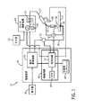
ここで、図を参照すると、図1は、本技法による溶接システム10の一実施形態のブロック図である。溶接システム10は、工作物14上で溶接アーク12を生成するように構成されている。溶接アーク12は、ミグ(MIG)、マグ(MAG)、種々の波形、タンデム構成等を含む任意のタイプの溶接のアークとすることができ、また任意の所望の方式において配置することができる。溶接システム10は、送電網のような電力源18に結合することができる電源装置16を含む。当然、発電機、エンジン駆動パワーパック等を含む、他の電力源を利用することもできる。例示の実施形態では、ワイヤ送給装置20がガス源22及び電源装置16に結合され、溶接用ケーブル27を通して、溶接トーチ26に溶接用ワイヤ24を供給する。電源装置16は溶接ワイヤ24に電気の流れを与え、溶接ワイヤは電極としての役割を果たす。溶接用ワイヤ24は溶接トーチ26を通して送給され、溶接アーク12を形成し、溶接アーク12によって溶融され、工作物14に堆積される。
Referring now to the drawings, FIG. 1 is a block diagram of one embodiment of a
ワイヤ送給装置20は通常、参照番号28によって包括的に示される制御回路を含み、制御回路はスプール30からの溶接用ワイヤ24の送給を調整し、電源装置16の出力を指示する。スプール30は、溶接動作中に消費される長さの溶接用ワイヤ24を含む。溶接用ワイヤ24は、通常、制御回路28の制御下で電気モーターを使用することを通して、ワイヤドライブアセンブリ32によって進められる。さらに、工作物14は、ワークケーブル36を接続されるクランプ34によって電源装置16に結合され、溶接用ワイヤ24と工作物14との間に溶接アーク12が確立されるときに電気回路を完成する。
The
溶接トーチ26を工作物14の近接した場所に配置することによって、電源装置16によって与えられ、溶接トーチ26に送られる電流が、溶接用ワイヤ24から工作物14へのアークを生成できるようになる。上記のように、このアーク放電は電源装置16、溶接トーチ26、工作物14及びワークケーブル36を含む電気回路を完成する。特に、動作時に、電流が電源装置16から、溶接トーチ26に、そして工作物14まで流れ、通常、電源装置16に再び接続される。アーク放電は、比較的大量の熱を生成し、それにより、工作物14の一部及び溶接用ワイヤ24の溶加材が溶融状態に移行し、それにより、溶接部を形成する。
By placing the
溶接エリアが溶接中に酸化又は汚染されないようにシールドするために、アーク性能を高めるために、かつ結果として生成される溶接部を改善するために、溶接システム10は、ガス源22から溶接トーチ26に不活性シールドガスを送給することもできる。しかしながら、溶接場所を保護するために、不活性シールドガスに加えて、又はその代わりに、活性ガス及び粒子状固体を含む種々のシールド材を利用できることに注目すべきである。
In order to shield the weld area from oxidation or contamination during welding, to enhance arc performance, and to improve the resulting weld, the
溶接システム10は、特に電源装置16上に設けられた作業者インターフェース38によって、作業者がデータ設定を選択することができるように設計することができる。作業者インターフェース38は、電源装置16の前面フェースプレートに組み込むことができ、溶接プロセスのタイプ、使用されるワイヤのタイプ、溶接パラメーター設定等の設定の選択を可能にすることができる。これらの溶接設定は、電源装置16内の制御回路40に通信される。本開示において、「GMAW」溶接が参照されるが、本明細書において説明される溶接トーチ26及び技法は、不活性ガスとともに用いることができるか、又はフラックス入りワイヤ又はメタルコアードワイヤの場合のように不活性ガスを用いることなく用いることができることに留意されたい。
The
制御回路40は、溶接システム10の溶接パラメーターを制御する。より具体的には、制御回路40は、所望の溶接動作を実行するために溶接用ワイヤ24に印加される溶接電力出力を制御するように動作する。したがって、制御回路40は、電力変換回路42に結合される。この電力変換回路42は、電力源18から電力を受け取り、出力電力を生成するように構成され、その出力電力は最終的に溶接トーチ26にある溶接ワイヤ24に印加される。チョッパー、昇圧回路、降圧回路、インバーター、コンバーター等を含む、種々の電力変換回路を用いることができる。
The
制御回路40は、溶接システム10内の至る所に配置されるセンサーから受信されるセンサーフィードバックに応じて出力電力を調整するように電力変換回路42を制御することができる。センサーは、溶接アーク12の電流、電圧又は光強度のような、溶接システムの動作パラメーターに関連する信号を与えることができる。これらの検出されたパラメーターに基づいて、制御回路40は、電力変換回路42に制御信号を出力し、溶接パラメーターを調整することができる。溶接パラメーターは、溶接用ワイヤ24に与えられる電流、溶接用ワイヤ24に与えられる電気の流れの電圧、溶接用ワイヤ送給速度、又はそれらの何らかの組み合わせを含むことができる。
The
制御回路40は、処理回路44及びメモリ回路46を含むことができ、種々のセンサーと通信可能に結合することができる。処理回路44は、溶接アーク12の光強度を検出するために用いられる光センサー48から、かつ電源装置16によって溶接ワイヤ24に与えられる電流を監視するように構成される電流センサー50からフィードバック信号を受信することができる。光センサー48は、溶接アーク12から放射される光を検出するために用いられる単一のセンサー又はセンサーアレイを表すことができる。幾つかの実施形態では、処理回路は電圧センサー52からのフィードバック信号も受信することができ、電圧センサー52は、溶接トーチ26及び工作物14内の接点間の電圧降下を測定するように設計される。受信されたフィードバック信号に基づいて、処理回路44は、メモリ回路46内に記憶される命令を実行して、1つ又は複数の制御信号を生成し、電力変換回路42に与えることができる。制御信号に従って、電力変換回路42は、溶接アーク12の所望のアーク長を保持するために、溶接用ワイヤ24に供給される溶接電力のパラメーターを絶えず調整することができる。より具体的には、溶接パラメーターを調整して、アーク長を所望のアーク長の約0%〜10%の範囲内に保持することができる。所望のアーク長は、作業者インターフェース38を介して与えられる溶接パラメーター及び/又はアーク開始パラメーターに関連する入力に基づくことができる。また、処理回路は、ワイヤ送給装置20の制御回路28と通信し、ワイヤ送給速度を調整する制御信号を与え、及び/又はワイヤ送給速度に基づく信号を受信することもできる。種々のセンサーが所定の間隔で異なる被検出信号を示す信号を生成することができ、処理回路は、センサー信号を受信し、概ね瞬時に制御信号を出力するようにセンサー信号を処理することができる。これにより、溶接動作全体を通して、溶接アーク12のアーク長の比較的瞬時の制御を可能にすることができる。
The
本実施形態では、制御回路40は、溶接ワイヤ24に供給される電流を示す(例えば、センサー50からの)信号に対して、溶接アーク12の光強度を示す(例えば、光センサー48からの)信号を変更するように構成される。溶接アーク12から放射される光は一般的に、市販の関連する応用形態において電流及びアーク長に正比例するので、この変更済み光強度は、溶接アーク12のアーク長の相対的に良好な指標である。被測定電流は、電極伸長、すなわち、溶接ワイヤ24が溶接トーチ26から突出する距離の変化とともに変化する場合がある。溶接ワイヤ24は工作物14に向かって絶えず進められ、工作物14上に溶滴として堆積されているので、電極伸長は経時的に変化する。制御回路40は、電流に対して光強度を変更することによって、電極伸長の変化から生じるアーク長の変化を調整する。上記で論じられたように、溶接システム10にわたる電圧降下のみを用いる場合、結果として生じるアーク長変化を監視することはできない。
In this embodiment, the
被検出光強度の変更は、被検出電流を補償するための任意の数の調整を含むことができる。「変更」という用語は、溶接パラメーターを制御するために用いられる被検出光強度と被検出電流との間の任意の調整、導出、補償又は包括的な関係を指す場合がある。例えば、幾つかの実施形態では、変更は、制御回路40内のルックアップテーブルを使用することを伴う場合がある。ルックアップテーブルは、異なる被検出電流値(又は電流値範囲)に対応する、変更済み光強度値又は光強度オフセット値を含むことができる。他の実施形態では、変更は、被検出光強度及び被検出電流を関連付ける式を含むことができる。光強度と電流との間の関係は、相対的割合、オフセット、又はそれらの何らかの組み合わせを含むことができる。後に詳細に説明される実施形態では、変更は、被検出電流に対する被検出光強度の正規化を含む。この結果として、正規化された光強度を生成することができる。制御回路40は、被検出光強度を、或る倍率を掛けた被検出電流で除算することによって、そのような正規化を実行する。開示される技法は、光強度を正規化する変更との関連で以下に説明されるが、被検出電流に対する被検出光強度の任意の適切な変更を用いて適用することができる。
Changing the detected light intensity can include any number of adjustments to compensate for the detected current. The term “modification” may refer to any adjustment, derivation, compensation or global relationship between the detected light intensity and the detected current used to control the welding parameters. For example, in some embodiments, the change may involve using a look-up table in the
被検出電流に対して正規化された被検出アーク光強度は、溶接トーチ26がいかに熱いか、用いられるケーブル配線の長さ若しくはタイプ、又は他の電圧寄与に関係なく、溶接プロセスのより実効的な制御を与えることができる。例えば、溶接ワイヤ24と工作物14上の溶接溜まり(weld puddle)との間の距離(すなわち、アーク長)が0に近づくにつれて、センサー48によって検出される光強度も0に近づく。これは、約20ボルトになる可能性もある陽極降下値及び陰極降下値を依然として測定する、センサー52によって検出される電圧とは対照的である。
The detected arc light intensity normalized to the detected current is more effective in the welding process, regardless of how hot the
別の例として、以下の導出は、溶接アーク12の正規化された光強度の変化が、アーク長の所与の増加の場合に測定される電圧の対応する変化より約10倍大きくできることを示す。再び、正規化された光強度は溶接アーク長に正比例する。溶接トーチ26のコンタクトチップから工作物14までの電圧降下は以下の式によって与えられる。

式1において、Vtotは全電圧降下である。Vcon、VEE、VA、VC及びVarcはそれぞれ、溶接トーチ26のコンタクトチップ、電極伸長、陽極、陰極及び溶接アーク12にわたる電圧降下を表す。溶接ワイヤ24に与えられる電流と、溶接ワイヤ24の電極伸長との所与の組み合わせの場合に、溶接システム10の他の部分にわたる電圧降下の和は相対的に一定のままである。
γの大きさは、通常のGMAW溶接システムの場合、約20ボルトとすることができる。溶接アーク12にわたる電圧降下は、溶接アーク12のアーク長に関連付けられる。
式3において、larcは溶接アーク長を表し、β≒20V/inである。溶接アーク12からの光出力は、以下の式に従って表すことができる。
式4において、Loutは光出力であり、λは、溶接アーク12にわたって送達される電流のアンペア当たりの溶接アーク12の単位長当たりの光出力である。その際、溶接アーク長の所与の変化について、電圧センサー52によって検出される電圧のパーセント変化は、以下の式によって表される。
式5において、%ΔVはパーセント電圧変化であり、V1及びV2はそれぞれ第1の被測定電圧及び第2の被測定電圧である。Δlarc1、Δlarc2、及びΔlarcはそれぞれ、第1の溶接アーク長、第2の溶接アーク長及び第1の溶接アーク長と第2の溶接アーク長との間の差である。上記で言及されたように、β及びγはいずれも概ね同じ値(例えば、20)を有するので、その式は以下のように更に簡単にすることができる。
上記の式6は被検出電圧と溶接アーク長の変化との間の関係を表す。以下の式は、所与の溶接電流の場合の、溶接アーク12から放射される光の変化と溶接アーク長の変化との間の関係を表す。
以下の2つの例は、溶接アーク長を制御するためのフィードバック変数として電圧を用いる場合と、溶接アーク長を制御するためのフィードバック変数としてアーク光を用いる場合との違いを示す。第1の例は、0.12インチから0.10インチへのアーク長の変化、すなわち、16.7%減少に応じたそれぞれの変化を表す。
次の例は、.10インチから.16インチへのアーク長の変化、すなわち、60%増加に応じたそれぞれの変化を表す。
上記の例に示すように、所与の溶接電流における光強度の変化は、溶接アーク12のアーク長の変化に比例する。アーク光強度(センサー48によって検出される)は、被検出電圧だけの場合より正確なアーク長の指標とすることができる。
As shown in the above example, the change in light intensity at a given welding current is proportional to the change in arc length of the
図2は、溶接システム10を動作させる方法70の一実施形態のプロセスフロー図である。方法70は、光センサー48を介して溶接アーク12の光強度を検出すること(ブロック72)と、電流センサー50を介して電極(例えば、溶接ワイヤ24)に与えられる電流を検出すること(ブロック74)とを含む。さらに、方法70は、制御回路40によって、被検出電流に対して被検出光強度を正規化し(ブロック76)、溶接アーク12の正規化された光強度を求めることを含む。方法70は、正規化された光強度に基づいて、溶接パラメーター(例えば、電源装置16からの電流出力又は電圧出力等)を制御すること(ブロック78)を更に含む。後に詳細に説明されるように、方法70に対する他の変形形態及び/又は追加形態を用いて、広範な溶接応用形態において溶接プロセスを制御することができる。
FIG. 2 is a process flow diagram of one embodiment of a
光強度信号を正規化すること(ブロック76)は、アーク長と、アーク光強度と、溶接アーク12を通って流れる電流との間の関係により、所望の溶接アーク長を保持するのに有用な場合がある。上記の導出に示すように、所与の電流レベルの場合に、被検出光強度は一般的に溶接アーク長に比例する。より具体的には、任意の所与の電流において、溶接ワイヤ24と工作物14との間に伸びるプラズマ柱である、溶接アーク12の全体積要素(volumetric element)は、その要素の温度に比例する量の光を放射する。アーク長が増加するにつれて、溶接アーク12の体積要素の数が増加し、その結果、それに応じて、放射される光の量も増加する。放射される全光とアーク長との間に結果として生じる関係は、以下の式によって与えられる。
式12では、λは単位長当たりの光要素数を表し、P(I)は電流Iにおける体積要素当たりの光出力を表す。溶接動作を制御する場合に望ましいように、アーク長が一定に保持される場合には、体積要素当たりの光出力は、以下の式に従って、その中に流れる電流の量に比例して増加する。
式13において、ηは、アンペア当たりの体積要素当たりの放射光を表す。結果として、式13を式12に代入して、溶接光強度を溶接アーク長及び電流に関連付ける以下の式をもたらすことができる。
上記の式14は、電極伸長の変化に起因する溶接アーク12にわたる電圧降下のいかなる変化とも無関係であることに留意されたい。しかしながら、溶接アーク12にわたって流れる電流は、溶接ワイヤ24の電極伸長とともに変化する場合がある。溶接ワイヤ24が溶接トーチ26から更に伸長するにつれて、例えば、溶接ワイヤ24内のジュール加熱が増加する場合がある。結果として、溶接ワイヤ24を溶融し、溶接池(weld pool)に移行するために用いられるエネルギーが減少し、これにより、溶接アーク12にわたる溶接電流が減少する。式14に示すように、光強度は溶接電流に比例するので、アーク長が変化しない場合であっても、溶接アーク12の光出力が低下する。それゆえ、溶接アーク長を適切に制御するために、方法70を参照しながら上記で説明したように、光強度を電流に対して正規化することが望ましい場合がある。この正規化は、以下の式において詳細に示される。
式15において、L* outは正規化された光強度を表す。具体的には、式14の光強度が、倍率ηを掛けた、溶接アーク12に流れる被検出電流で除算される。式15は、以下の式16に変化し、式16は正規化された光強度をアーク長制御変数に直接関連付ける。正規化された光強度はアーク長に正比例することができ、それにより、検出された電圧降下より正確なフィードバック変数になる。
正規化された光強度は溶接アーク長の変化に敏感に反応するので、パルススプレーGMAW溶接プロセスのような或る特定のGMAW溶接との関連において、より正確な制御を提供することができる。そのような溶接は、多くの場合に方形パルス法を用いて、電極に与えられる高い溶接電流と低い溶接電流との間のサイクルを処理する。しかしながら、アーク光強度フィードバックを通して提供される高感度の制御によれば、平均溶接電流上に正弦波を重ね合わせることによって、適応的なパルス波形を生成できるようになる場合がある。単一周波数の正弦波形を用いて溶接プロセスを進めることは、従来の方形パルスより優れた利点を提供することができる。例えば、正弦波制御は、ピークパルスアンペア数から一定の割合で徐々に上昇及び降下することに起因して、広範なスペクトル電磁雑音のレベルを下げることができる。電磁雑音が減少すると、特定の周波数においてパルスを生成するときに、システムからの可聴雑音出力が減少することにつながる場合がある。さらに、初期電流からピーク電流に、そしてその逆に滑らかに移行することは、そのように移行していなければ溶接ワイヤ24の先端において生じることになった望ましくない溶融を少なくすることができる。
Since the normalized light intensity is sensitive to changes in the welding arc length, it can provide more precise control in the context of certain GMAW welding, such as a pulse spray GMAW welding process. Such welds often use a square pulse method to handle cycles between high and low welding currents applied to the electrodes. However, the sensitive control provided through arc light intensity feedback may allow an adaptive pulse waveform to be generated by superimposing a sine wave on the average welding current. Proceeding the welding process with a single frequency sinusoidal waveform can provide advantages over conventional square pulses. For example, sinusoidal control can reduce the level of broad spectrum electromagnetic noise due to a gradual rise and fall from the peak pulse amperage at a constant rate. Decreasing electromagnetic noise may lead to a decrease in audible noise output from the system when generating pulses at specific frequencies. In addition, a smooth transition from initial current to peak current and vice versa can reduce undesirable melting that would otherwise have occurred at the tip of the
方法70を用いて、正弦波形を連続して調整して、正規化された光強度測定によって特定されるようなアーク長の変化に対処することができる。幾つかの実施形態では、正規化された光強度による制御は、溶滴の脱離から生じるアーク長変化に応じて溶接パラメーターを調整することができる。すなわち、溶接ワイヤ24がコンタクトチップにおいて溶融するとき、溶融した溶接ワイヤ24の溶滴が滴下され、堆積して、工作物14上の溶接部になる。溶滴が滴下されるにつれて、アーク長が減少し、制御回路40が溶接ワイヤ24に流れる電流を増加させることができ、それにより、溶滴移行を容易にすることができる。溶接パラメーターを制御するのに電圧フィードバックに頼る従来の溶接システムでは、一般的に、このようにして溶滴移行が助長されることはない。電流を増加させて溶滴を滴下する代わりに、そのようなシステムは、溶滴形成に起因する被検出電圧の増加に応じて、電流を減少させることになる。
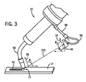
図3は、取付装置88によって溶接トーチ26に取り付けられる光センサー48を有する、溶接トーチ26の一実施形態の斜視図である。溶接アーク12からの光を光センサー48によって取り込むことができ、光センサーが、被検出光強度を、処理するために制御回路40に送信される電子信号に変換する。例示の実施形態では、光センサー48は、フィードバック信号を、ワイヤ90を介して制御回路40に通信し、ワイヤは溶接ケーブル27を通って、ワイヤ送給装置20から電源装置16まで延在することができる。しかしながら、他の実施形態では、光センサー48は、信号を無線で通信することができる。制御回路40は、溶接ワイヤ24を通って流れる被検出電流に対して信号を正規化することができ、正規化された光強度に基づいて、電力変換回路42に制御信号を与えることができる。その後、電力変換回路42は、溶接ワイヤ24への電力出力を調整し、所望のアーク長を、そして結果として一貫した溶接ビード92を保持することができる。
FIG. 3 is a perspective view of one embodiment of the
光センサー48は、入射光に応じて電気信号を出力することができる任意のデバイスを含むことができる。例えば、光センサー48は、1つ若しくは複数の光起電セル、フォトダイオード、感光素子又はそれらの組み合わせを含むことができる。幾つかの実施形態では、光センサー48は、被検出光に線形に比例する電気信号を出力するように構成することができる。他の実施形態では、光センサー48内の非線形性を、制御回路40によって、対応する線形化関数に写像することができる。
The
光センサー48は、溶接アーク12に対して特定の場所及び向きにおいて、取付装置88によって溶接トーチ26に取り付けることができる。溶接アーク12の位置及び/又は形状は、溶接プロセス全体を通して、特に溶接ワイヤ24の電極伸長の変化とともに変化する場合がある。例えば、溶接トーチ26に対する溶接アーク12の位置は、電極伸長が変化することに起因して、約1インチまで変化する場合がある。それゆえ、光センサー48は、所与の時点の溶接トーチ26に対する溶接アーク12の厳密な位置に関係なく、溶接アーク12から放射される光強度を安定して検出するように構成することができる。光センサー48は、溶接トーチ26に対して、光センサー48の検出面の軸94が溶接トーチ26のノズル98と位置合わせされる軸96に対して平行になるような位置に取り付けることができる。結果として、工作物14に対するこれらの軸96及び94の角度θ1及びθ2は補角とすることができる。さらに、光センサー48は、光センサー48上で光の所望の入射角θ3を与えるように、すなわち、軸94と光センサー48から溶接アーク12へのライン100との間に所望の角度を与えるように取り付け、及び/又は調整することができる。ライン100の距離及び入射角θ3は、工作物14上の溶接溜まり又は任意のシステム構成要素によって遮られることなく、溶接アーク12から放射される光の全てが光センサー48の検出面上で捕捉されるのを確実にするように調整することができる。
The
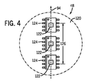
図4は、光センサー48の検出面120に対して垂直に見た光センサー48の一実施形態を示す。例示の実施形態では、光センサー48は、それぞれ別々のチップ124上に位置する3つの光起電センサー122の線形アレイを含む。チップ124は、接続された光起電センサー122によって検出された入射光を電気信号に変換するように構成される回路を含むことができる。光起電センサー122は、電気的に直列に接続することができ、それにより、光起電センサー122のそれぞれに達する光の量の示す信号を合成して1つの電気信号とすることができ、その信号が光センサー48から出力される。光起電センサー122が取り付けられる検出面120、又はハウジングは、例示されるように円形にすることができるか、又は任意の他の所望の形状にすることができる。光起電センサー122は、軸94に沿って線形に配置され、その軸は、軸96と実質的に(例えば、或る特定の実施形態では、約1度〜2度未満の許容範囲内で)平行であり、それゆえ、ノズル98から出る溶接ワイヤ24と実質的に平行である。光起電センサー122は、センサーアレイの上縁と底縁との間の長手方向距離126が少なくとも所望の距離であるように配置することができる。この所望の距離は、溶接ワイヤ24の電極伸長の予想される変動に関連付けることができ、それにより、溶接アーク12の場所が光センサー48に対してシフトする場合であっても、光起電センサー122は、溶接アーク12の全長からの光を検出する。光センサー48の他の実施形態は、溶接アーク12から放出される全光強度を示す信号を生成するために用いられる異なる数、タイプ及び配置の検知素子を含むことができる。
FIG. 4 illustrates one embodiment of the
溶接アーク12から放射される光は極めて強いので、相対的に高い電流が溶接アーク12にわたって保持されるときに特に、光起電センサー122を飽和させる可能性がある。光起電センサー122を完全に飽和させないようにするために、光センサー48は、光起電センサー122の上方に濃度フィルターを含むことができる。他の実施形態では、光センサー48から溶接アーク12までの距離(例えば、ライン100)を長くすることができ、入射角θ3を変更することができ、及び/又は工作物14に対する溶接トーチ26の角度θ1を、完全に飽和する可能性を下げるように変更することができる。
The light emitted from the
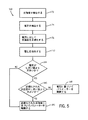
正規化された光強度だけを用いて、溶接パラメーターを制御することに加えて、溶接システム10の幾つかの実施形態は、正規化された光強度と組み合わせて電圧フィードバックを用いて、溶接プロセスのフィードバック制御を提供することができる。このタイプの制御の一例として、図5は、被検出光強度、被検出電流及び被検出電圧に基づいて溶接システム10を動作させる方法140の一実施形態のプロセスフロー図である。方法140は、図2の方法70を参照しながら詳細に説明されたような、光センサー48によって光強度を検出すること(ブロック72)と、電流センサー50によって電流を検出すること(ブロック74)と、検出電流に対して検出光強度を正規化すること(ブロック76)とを含む。また、方法140は、電圧センサー52によって、電源装置16から溶接ワイヤ24に与えられる電圧を検出すること(ブロック142)も含む。この被検出電圧は、溶接トーチ26及びワークケーブル36における接点間の電圧降下も含むことができる。電圧センサー52は、正規化された光強度とともに処理するために、被検出電圧を示す信号を制御回路40に送信することができる。
In addition to controlling welding parameters using only normalized light intensity, some embodiments of the
方法140の残りは、被検出電圧及び正規化された光強度に基づいて、溶接パラメーター(例えば、電流、電圧等)を(電力変換回路42に制御信号を与えることによって)制御することを含む。或る特定の実施形態では、方法140は、被検出電圧が所定のしきい値より大きいか否かを判断する(ブロック144)。また、方法140は、正規化された光強度が所定のしきい値より大きいか否かを判断すること(ブロック146)も含むことができる。
The remainder of
ブロック144、146は、制御回路40が2つの入力信号(正規化された光強度及びアーク電圧)を評価し、どちらの信号を有効であると見なすべきであるかを判断することを表すことができる。幾つかの実施形態では、制御回路40は、これらの入力信号に基づいて計算された制御信号を評価して、どちらの制御信号が電力変換回路42に送信されるべきであるかを判断することができる。例えば、被検出電圧を示す信号が電圧しきい値より大きいが、正規化された光強度を示す信号が光強度しきい値以下である場合には、制御回路40は、被検出電圧に基づいて溶接パラメーターを制御することができる(ブロック148)。これは、制御回路40が、正規化された光強度に基づいて、溶接アーク12から放射された光が光センサー48の視野から遮られると判断するときに行うことができる。例えば、工作物14の一部が、溶接アーク光が光センサー48に達するのを遮るように、溶接トーチ26が工作物14に対して向けることができる。結果として、光センサー48によって検出された光、そしてその結果、正規化された光強度がしきい値以下になる。しかしながら、溶接アーク12にわたる電圧降下のため、電圧センサー52は、対応するしきい値より大きい電圧を検出することができる。この時点で、溶接システム10は、被検出光信号を劣化していると見なすことができる。正規化された光強度が低いことに応じて溶接ワイヤ24に供給される電力を増加させると、溶接ワイヤ24を過熱する可能性があるので、その代わりに、制御回路40は電圧フィードバック制御に切り替えることができる。制御回路40は、被検出電圧に基づいて、溶接パラメーターを調整するために電力変換回路42に制御信号を与えることができる。正規化された光強度が、もはや遮られていないか、又は劣化していないことを示す正常(そのしきい値より大きい)レベルに戻る時点まで、電圧フィードバックを用いることができる。このようにして、電圧測定は、光強度測定に対するフェールセーフの役割を果たす。
被検出電圧及び正規化された光強度がいずれも、それぞれのしきい値より大きいと判断されるとき(ブロック144、146)、方法140は、正規化された光強度に基づいて、溶接パラメーターを制御すること(ブロック150)を含むことができる。電圧測定は、正規化された光強度が有効であることを確認する役割を果たす。上記で論じられたように、正規化された光強度は被検出電圧に比べて相対的に正確な溶接アーク長の指標であるので、その後、正規化された光強度を制御入力として用いることができる。
When it is determined that both the detected voltage and the normalized light intensity are greater than the respective thresholds (
被検出電圧が電圧しきい値より小さいと判断される場合には(ブロック144)、これは短絡を指示することができる。溶接システム10は、この判断の結果として、正規化された光強度に基づいて制御信号を適用することによって、短絡を解消することができる。溶接システム10の他の実施形態は、調整金属堆積プロセス(regulated metal deposition process)のような短絡を解消するルーチンを実行するために、電圧フィードバックに切り替えることによって短絡を解消することができる。
If it is determined that the detected voltage is less than the voltage threshold (block 144), this can indicate a short circuit. As a result of this determination, the
制御回路40によって被検出電圧を用いて、正規化された光強度信号のためのフェールセーフ以外の他の制御機能を実行することができる。例えば、制御回路40は、光センサー48、電流センサー50及び電圧センサー52からの情報を用いるハイブリッド制御に基づいて溶接アーク12を制御するための信号を与えることができる。一例として、正規化された光強度を被検出電圧とともに用いて、調整金属堆積(RMD)プロセスを制御することができる。RMDプロセスは、溶接ワイヤ24が溶接アーク12を短絡するように、電力出力を制御することができる。そのようなプロセスでは、溶接アーク12にわたる電圧降下は、溶接ワイヤ24から落下する溶融した材料柱のくびれに関連する情報を与えることができる。正規化された光強度を用いて、このプロセス全体を通して所望の溶接アーク長を保持することができ、一方、被検出電圧を用いて、金属堆積に関連するパラメーターを監視することができる。その結果、RMDプロセスは、金属堆積の制御を依然として保持しながら、アーク長の変化に対する相対的に敏感な反応を利用することができる。電圧フィードバックは、他の溶接応用形態においても、正規化された光強度を通して利用可能な制御を向上させることができる。例えば、制御回路40は、電力出力を制御するのに正規化された光強度によるフィードバック信号に主に頼ることができ、被検出電圧から判断することができる電極伸長情報に基づいて、溶接電流を微調整することができる。
The
被検出電流に対して被検出光強度を正規化することによって、溶接ワイヤ24が溶接システム10を通して進められるワイヤ送給速度に関係なく、溶接アーク12の一貫した長さを保持することができる。より具体的には、溶接システム10は、ワイヤ送給装置20のワイヤ送給速度が調整されるのに応じて、正規化された光強度に基づいて溶接パラメーターを自動的に調整し、所望のアーク長を保持することができる。図6は、ワイヤ送給装置20のワイヤ送給速度の変化に伴って生じる場合がある、溶接パラメーターに対する自動調整の一例を示すプロット160である。例示されるプロット160は、時間(横座標164)に対する溶接パラメーター(縦座標162)を示す。溶接パラメーターは、溶接アーク12を生成するために溶接ワイヤ24に与えられる電流(トレース166)及び電圧(トレース168)を含む。時間T1から時間T2まで、ワイヤ送給速度は、約240インチ毎分から約600インチ毎分まで徐々に増加する。ワイヤ送給速度が上昇するにつれて、電源装置16によって溶接ワイヤ24に供給される電力の電流及び電圧も増加する。
By normalizing the detected light intensity with respect to the detected current, a consistent length of the
溶接システム10において、正規化された光強度による制御によって、ワイヤ送給速度が変化するのに応じて、所望の溶接アーク長を保持しながら、溶接パラメーターを自動的に調整できるようになる場合がある。これにより、作業者が、ワイヤ送給速度を調整する際に溶接電圧を手動で調整する必要はないので、溶接パラメーターを容易に設定できるようにすることができる。このタイプの自動制御は、一定のアーク長を保持するために一定の電圧出力を与える従来の溶接システムを用いては不可能な場合がある。そのようなシステムでは、ワイヤ送給速度の変化は、電圧とアーク長との間の関係に影響を及ぼす場合がある。したがって、所望の溶接アーク長を保持するために、作業者は、それに応じて電源装置16の電圧設定を変更しなければならない。光強度フィードバックを用いる電流及び電圧両方の自動制御は、溶接プロセス全体を通してワイヤ送給速度が変更されるモードにおいて、溶接システム10の性能を改善することができる。例えば、正規化された光強度を用いて、溶接ビードの見栄えのする所望の外見を達成するためにワイヤ送給速度が定期的に変更される時変堆積モードにおいて動作する溶接システム10を制御することができる。
In the
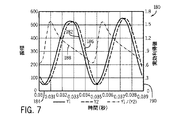
被検出光強度を正規化する際に、光強度を示す信号及び溶接電流を示す信号が互いに同相である場合にのみ、式15の出力を式16に変換できることに留意されたい。センサー48及び50から受信された信号が同相でない場合には、制御回路40は、光強度正規化中に適切な利得係数を適用することができる。光及び電流の物理的パラメーターは実際に同相において生じるが、センサー48及び50によって生成される信号は、制御回路40によって信号に電子フィルターが適用された後に、位相がずれる場合がある。図7は、検知されたパラメーター間の位相シフトのために適した実効利得値を示すプロット180である。トレース182は、時間184に対する第1のパラメーター信号(例えば、被検出光強度)を表し、トレース186は、時間184に対する第2のパラメーター信号(例えば、被検出電流)を表す。別のトレース188は、第1のトレース182の振幅を第2のトレース186の振幅で除算することによって求められる、時間184に対する実効利得値190を表す。具体的には、第3のトレース188は、同じ周波数及び振幅の2つの正弦波(トレース182、186)間の位相シフトの影響を示す。遅れている波形(トレース186)は、被検出電流を示す信号を、約0.00022秒のフィルター時定数でRCフィルターをかけた影響を表すことができる。例示の実施形態では、この除算から生じる実効利得値190は、正弦波の各周期にわたって、約0.64〜1.56の間で変化する場合がある。制御回路40は、被検出光強度の正確な正規化を実行するために、かつ溶接パラメーターの安定した制御を提供するために、被検出信号間の位相シフトに起因して実効利得値190を制御するように構成することができる。より具体的には、正規化ステップは、位相シフトに基づいて実効利得値を求めることと、被検出光強度を被検出電流で除算することと、実効利得値に従って除算後の光強度を補正することとを含むことができる。
When normalizing the detected light intensity, it should be noted that the output of
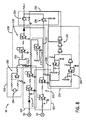
図8は、被検出光強度を正規化するために、かつ正規化された光強度に基づいて溶接パラメーターを制御するために用いられる制御回路40の一実施形態の概略図である。制御回路40は、被検出光強度及び被検出電流を示す信号を受信し、少なくとも1つには正規化された光強度信号に基づいて、制御信号を電源装置16に与えるように構成される。例示される制御回路40は、正規化された光強度に基づいて制御信号を決定し、被検出電圧を示す信号に基づいて制御信号を決定し、図5を参照しながら説明したように制御信号を切り替えることを可能にする。制御回路40は、異なる機能を実行する幾つかのブロックに分割される。図示される回路は例示であり、個々の回路構成要素の他の組み合わせを利用して、以下に説明される機能を実行できることに留意されたい。さらに、制御のための入力として電圧が与えられるか否か、又は溶接システム10によって実行される制御のタイプのような要因に応じて、制御回路40の実施形態によっては、或る特定の機能ブロックが存在する場合もあり、存在しない場合もある。
FIG. 8 is a schematic diagram of one embodiment of a
制御回路40の第1のブロック200は、入力光強度信号204を調整するための高インピーダンス差動増幅器202を含むことができる。信号204は、図1に示すように、光センサー48によって生成することができ、第1のブロック200における電圧降下として入力することができる。第1のブロック200は、溶接アーク12の単位長当たりの光要素数に対応する約λの利得を適用するように構成することができる。調整済み信号は制御回路40の第2のブロック208内の除算器ユニット206の分子位置に入力される。
The
制御回路40の第3のブロック210は、電流センサー50から受信された被検出電流信号を調整することができる。より具体的には、第3のブロック210は、ηに対応する利得を適用するように構成される可変利得演算増幅器212を含むことができる。このようにして電流信号が調整されると、その信号は、第2のブロック208内の除算器ユニット206の分母に与えることができる。例示される除算器ユニット206は、上記の式16と一致する出力を生成するように構成することができる。しかしながら、例示の実施形態では、除算器ユニット206は、以下の式に従って、分母において更なる項γを受信する。
式17の更なる項γは、電流信号が0に近づくときに除算器ユニット206がレール電圧を生じないように、すなわち最大出力を生成しないように含まれる場合がある。更なる項γは制御回路40の第4のブロック216に示すように、ポテンショメーター214によって設定することができる。除算器ユニット206に加えて、第2のブロック208は、除算器ユニット206の出力を調整し、正規化された光強度信号を電力変換回路42に入力するのに適したレベルに合わせて増減する演算増幅器218を含むことができる。これは、式4に従って、正規化された光強度にλを掛けて増減し、アーク長に関連する信号を求めることを伴うことができる。
An additional term γ in Equation 17 may be included so that
例示の実施形態では、制御回路40は、信号が所定のしきい値にいかに関連しているかに応じて、正規化された光強度によるフィードバックと電圧フィードバックとを切り替えるように構成される。それゆえ、例示される制御回路40は、電圧センサー52から被検出電圧信号を受信し、その信号を電力変換回路42に入力するのに適した制御信号に変換するための第5のブロック220も含む。これは、式3に従って、演算増幅器222によって、電圧信号にβを掛けて増減し、アーク長に関連する信号を求めることを含むことができる。
In the illustrated embodiment, the
第6のブロック224は、図5を参照しながら説明したように、光フィードバック信号及び電圧フィードバック信号を所定のしきい値と比較するための論理セクションとしての役割を果たす。第6のブロック224は、第2のブロック208及び第5のブロック220から入力を受信することができる。第2のブロック208からの入力は、正規化された光強度に基づく制御信号であり、第1のコンパレーター226に与えられ、その信号を所定のしきい値と比較することができる。同様に、第5のブロック220からの入力は、電圧に基づく制御信号であり、第2のコンパレーター228に与えられ、その信号を第2のしきい値と比較することができる。その際、コンパレーター226、228の出力は、第6のブロック224内の一連の論理ゲート230への入力としての役割を果たすことができる。
The
第7のブロック232は、2つのスイッチ234、236を含み、それらのスイッチはコンパレーター226、228の出力に応じて第6のブロック224の論理ゲート230によって駆動することができる。例えば、コンパレーター226によって判断されるように、正規化された光強度に基づく制御信号が所定のしきい値より大きい場合があり、コンパレーター228によって判断されるように、被検出電圧に基づく制御信号が所定のしきい値より大きい場合がある。これらの判断に応じて、論理ゲート230は、第1のスイッチ234に、スイッチ324を閉じるための信号を送信し、それにより、正規化された光強度に基づく制御信号を電力変換回路42に与えることができる。しかしながら、光センサー48が溶接アーク12からの光の見通しを遮られる場合には、コンパレーター226によって判断されるように、正規化された光強度に基づく制御信号が所定のしきい値より小さい場合がある。同時に、コンパレーター228によって判断されるように、被検出電圧に基づく制御信号が所定のしきい値より大きいままである場合がある。コンパレーター226、228からのそのような入力に応じて、論理ゲート230は、第2のスイッチ236に、スイッチ236を閉じるための信号を与えることができる。これにより、正規化された光強度信号が劣化しているときにはいつでも、被検出電圧に基づく制御信号が電力変換回路42に与えられる。
The
制御回路40の他の構成も可能な場合がある。例えば、或る特定の実施形態では、制御回路40は、溶接パラメーターの制御が正規化された光強度に完全に基づくように、最初の4つのブロック200、208、210、216のみを含むことができる。他の実施形態では、正規化された光強度に基づく制御信号と、電圧に基づく制御信号とを組み合わせて、電力変換回路42にハイブリッド制御信号を与えるために、更なる論理回路が存在する場合がある。更に別の実施形態では、正規化された光強度に基づく制御信号を用いて、或る特定の溶接パラメーターを制御することができ、被検出電圧に基づく制御信号を用いて、異なる溶接パラメーターを制御することができる。
Other configurations of the
光センサー48の本実施形態を用いて、完全自動及び半自動の両方の溶接システム10内の溶接パラメーターを制御することができる。より具体的には、光センサー48は、ロボット制御で操作されるか、又は作業者によって手動で操作される溶接トーチ26に取り付けることができる。作業者が溶接トーチ26を位置決めする或る特定の実施形態では、光センサー48は、溶接トーチ26上の場所以外の場所に取り付けられることが望ましい場合がある。一例として、図9は、溶接作業者252によって装着される溶接用ヘルメット250に取り付けられるセンサー48の一実施形態の斜視図を提供する。溶接トーチ26を実効的に操作し、高品質溶接部を作り出すために、作業者252は、一般的に、溶接アーク12が遮られることなく見通せるように保持する。したがって、溶接用ヘルメット250の前縁上に光センサー48を位置決めすることによって、溶接アーク12から放射された光の適切な検出を確保することができる。上記で論じられたように、光センサー48は、単一の光センサーか、又は図4に示されるアレイのような光センサーのアレイを含むことができる。
With this embodiment of the
光センサー48上に入射する光は、光センサー48と溶接アーク12との間の距離の関数である。光センサー48は溶接トーチ26に直接取り付けられないので、光センサー48と溶接トーチ26との間の距離は、溶接プロセス全体を通して変化する場合がある。それゆえ、光センサー48から溶接アーク12までの距離を検出することが有用な場合がある。これは種々の方法において成し遂げることができる。例えば、光センサー48は、溶接アーク12から光センサー48までの正弦波の飛行時間を測定する構成要素を含むか、又はそのような構成要素と結合することができる。制御回路40は、光センサー48上に入射する光と、光センサー48と溶接アーク12との検出された近さとに基づいて、光強度を求めることができる。或る特定の実施形態では、溶接システム10は、光センサー48と溶接アーク12との間の距離に対して、被検出光強度信号を補償されないままにしておくことができる。そのような実施形態では、作業者252は、溶接アーク12に対して溶接用ヘルメット250上の光センサー48を動かすことによって(矢印254)、溶接アーク長を制御することができる。これは、正規化された光強度によるフィードバックを通して入手可能なアーク長の変化に対する感度を保持しながら、作業者252による制御性を高めることができる。例示されるように、光センサー48は、信号を制御回路40に無線で通信することができる。これは、光センサー48がヘルメット250に取り付けられ、その結果、作業者が電源装置16に対して自由に動くことができる実施形態の場合に望ましいことがある。
The light incident on the
本明細書において、本発明の或る特定の特徴だけが図示及び説明されてきたが、当業者には多くの変更及び変形が思い浮かぶであろう。それゆえ、添付の特許請求の範囲は、本発明の真の趣旨に入る全ての変更及び変形を包含することを意図していることを理解されたい。 Although only certain specific features of the invention have been illustrated and described herein, many modifications and changes will occur to those skilled in the art. Therefore, it is to be understood that the appended claims are intended to cover all modifications and variations that fall within the true spirit of the invention.
10 溶接システム
12 溶接アーク
14 工作物
16 電源装置
18 電力源
20 ワイヤ送給装置
22 ガス源
24 溶接ワイヤ
26 溶接トーチ
27 溶接用ケーブル
28 制御回路
30 スプール
32 ワイヤドライブアセンブリ
34 クランプ
36 ワークケーブル
38 作業者インターフェース
40 制御回路
42 電力変換回路
44 処理回路
46 メモリ回路
48 光センサー
50 電流センサー
52 電圧センサー
88 取付装置
90 ワイヤ
92 溶接ビード
98 ノズル
100 ライン
120 検出面
122 光起電センサー
124 チップ
126 長手方向距離
DESCRIPTION OF
Claims (20)
溶接アークの光強度を検知するように構成される第1のセンサーと、
電源装置によって電極に与えられる電流を検知するように構成される第2のセンサーと、
前記第1のセンサー及び前記第2のセンサーに通信可能に結合され、前記電流に対して前記光強度を変更するように構成されるコントローラーであって、該コントローラーは前記変更済み光強度に基づいて該溶接システムの溶接パラメーターを制御するように構成されるコントローラーとを備える溶接システム。 A welding system,
A first sensor configured to detect the light intensity of the welding arc;
A second sensor configured to sense a current applied to the electrode by the power supply;
A controller communicatively coupled to the first sensor and the second sensor and configured to change the light intensity relative to the current, the controller based on the changed light intensity A welding system comprising a controller configured to control welding parameters of the welding system.
前記コントローラーは、前記第3のセンサーに通信可能に結合され、前記変更済み光強度が光強度しきい値より小さく、かつ前記検知された電圧が電圧しきい値より大きいときに、前記電圧に基づいて前記溶接パラメーターを制御するように構成される請求項1に記載の溶接システム。 A third sensor configured to sense a voltage of the electrical flow applied to the electrode by the power supply;
The controller is communicatively coupled to the third sensor, based on the voltage when the modified light intensity is less than a light intensity threshold and the sensed voltage is greater than a voltage threshold. The welding system of claim 1, wherein the welding system is configured to control the welding parameters.
電流センサーによって、前記溶接システムの電源装置から前記電極に与えられる電流を検出することと、
前記溶接システムの制御回路によって、前記被検出電流に対して前記被検出光強度を変更することであって、前記溶接アークの変更済み光強度を求めることと、
前記変更済み光強度に基づいて前記溶接システムの溶接パラメーターを制御することとを含む方法。 Detecting the intensity of light emitted from the welding arc generated between the electrode of the welding system and the workpiece by means of an optical sensor;
Detecting a current applied to the electrode from a power supply device of the welding system by a current sensor;
By the control circuit of the welding system, changing the detected light intensity with respect to the detected current, obtaining a changed light intensity of the welding arc;
Controlling welding parameters of the welding system based on the altered light intensity.
前記変更済み光強度に基づいて、前記溶接アークが前記光センサーの視野から遮られるか否かを判断することと、
前記溶接アークが前記光センサーの視野から遮られるときに、前記被検出電圧に基づいて前記溶接パラメーターを制御することとを含む請求項11に記載の方法。 Controlling the welding parameters is
Determining whether the welding arc is obstructed from the field of view of the light sensor based on the changed light intensity;
12. The method of claim 11, comprising controlling the welding parameter based on the detected voltage when the welding arc is interrupted from the field of view of the light sensor.
前記被検出光強度と前記被検出電流との間の位相シフトに基づいて利得係数を求めることと、
前記被検出光強度を前記被検出電流で除算することと、
前記利得係数に従って前記除算後の光強度を補正することとを含む請求項10に記載の方法。 Changing the light intensity
Obtaining a gain coefficient based on a phase shift between the detected light intensity and the detected current;
Dividing the detected light intensity by the detected current;
11. The method of claim 10, comprising correcting the divided light intensity according to the gain factor.
前記溶接システムの電極と工作物との間の溶接アークの光強度を示す信号を受信し、
前記溶接アークを生成するために前記電極に供給される電流を示す信号を受信し、
前記電流を示す信号に対して前記光強度を示す信号を変更し、
前記光強度を示す前記変更済み信号に基づいて前記溶接システムの電源装置に制御信号を与えるように構成される制御回路を備える溶接システム。 A welding system,
Receiving a signal indicative of the light intensity of the welding arc between the electrode of the welding system and the workpiece;
Receiving a signal indicative of a current supplied to the electrode to generate the welding arc;
Changing the signal indicating the light intensity with respect to the signal indicating the current;
A welding system comprising a control circuit configured to provide a control signal to a power supply device of the welding system based on the changed signal indicative of the light intensity.
前記変更済み信号を光強度しきい値と比較し、
前記電圧信号を電圧しきい値と比較し、
前記変更済み信号に基づいて第1の制御信号を決定し、
前記電圧信号に基づいて第2の制御信号を決定し、
前記変更済み信号が前記光強度しきい値より大きいときに前記第1の制御信号を前記電源装置に与え、
前記電圧信号が前記電圧しきい値より大きく、かつ前記変更済み信号が前記光強度しきい値より小さいときに前記第2の制御信号を前記電源装置に与えるように構成される請求項19に記載の溶接システム。 The control circuit includes:
Comparing the modified signal to a light intensity threshold;
Comparing the voltage signal to a voltage threshold;
Determining a first control signal based on the changed signal;
Determining a second control signal based on the voltage signal;
Providing the first control signal to the power supply when the changed signal is greater than the light intensity threshold;
20. The second control signal is configured to be provided to the power supply when the voltage signal is greater than the voltage threshold and the modified signal is less than the light intensity threshold. Welding system.
Applications Claiming Priority (3)
| Application Number | Priority Date | Filing Date | Title |
|---|---|---|---|
| US13/733,681 | 2013-01-03 | ||
| US13/733,681 US10065260B2 (en) | 2013-01-03 | 2013-01-03 | System and method for controlling an arc welding process |
| PCT/US2013/077710 WO2014107387A1 (en) | 2013-01-03 | 2013-12-24 | System and method for controlling an arc welding process |
Publications (2)
| Publication Number | Publication Date |
|---|---|
| JP2016508071A true JP2016508071A (en) | 2016-03-17 |
| JP2016508071A5 JP2016508071A5 (en) | 2017-02-09 |
Family
ID=49950092
Family Applications (1)
| Application Number | Title | Priority Date | Filing Date |
|---|---|---|---|
| JP2015551725A Pending JP2016508071A (en) | 2013-01-03 | 2013-12-24 | System and method for controlling an arc welding process |
Country Status (11)
| Country | Link |
|---|---|
| US (1) | US10065260B2 (en) |
| EP (1) | EP2941329A1 (en) |
| JP (1) | JP2016508071A (en) |
| KR (1) | KR102138738B1 (en) |
| CN (1) | CN104903042B (en) |
| AU (1) | AU2013371390B2 (en) |
| BR (1) | BR112015015995A2 (en) |
| CA (1) | CA2887608A1 (en) |
| IN (1) | IN2015DN02932A (en) |
| MX (1) | MX345201B (en) |
| WO (1) | WO2014107387A1 (en) |
Families Citing this family (49)
| Publication number | Priority date | Publication date | Assignee | Title |
|---|---|---|---|---|
| US10040143B2 (en) | 2012-12-12 | 2018-08-07 | Illinois Tool Works Inc. | Dabbing pulsed welding system and method |
| US10906114B2 (en) | 2012-12-21 | 2021-02-02 | Illinois Tool Works Inc. | System for arc welding with enhanced metal deposition |
| US9950383B2 (en) | 2013-02-05 | 2018-04-24 | Illinois Tool Works Inc. | Welding wire preheating system and method |
| US10835983B2 (en) | 2013-03-14 | 2020-11-17 | Illinois Tool Works Inc. | Electrode negative pulse welding system and method |
| US11045891B2 (en) | 2013-06-13 | 2021-06-29 | Illinois Tool Works Inc. | Systems and methods for anomalous cathode event control |
| US10828728B2 (en) | 2013-09-26 | 2020-11-10 | Illinois Tool Works Inc. | Hotwire deposition material processing system and method |
| US11154946B2 (en) * | 2014-06-30 | 2021-10-26 | Illinois Tool Works Inc. | Systems and methods for the control of welding parameters |
| US11198189B2 (en) | 2014-09-17 | 2021-12-14 | Illinois Tool Works Inc. | Electrode negative pulse welding system and method |
| US10643495B2 (en) | 2014-09-19 | 2020-05-05 | Realityworks, Inc. | Welding speed pacing device |
| US10446057B2 (en) | 2014-09-19 | 2019-10-15 | Realityworks, Inc. | Welding speed sensor |
| US11478870B2 (en) | 2014-11-26 | 2022-10-25 | Illinois Tool Works Inc. | Dabbing pulsed welding system and method |
| US10189106B2 (en) | 2014-12-11 | 2019-01-29 | Illinois Tool Works Inc. | Reduced energy welding system and method |
| US10773329B2 (en) | 2015-01-20 | 2020-09-15 | Illinois Tool Works Inc. | Multiple input welding vision system |
| CN107912061B (en) | 2015-03-06 | 2021-06-01 | 伊利诺斯工具制品有限公司 | Sensor assisted head mounted display for welding |
| WO2016144744A1 (en) | 2015-03-09 | 2016-09-15 | Illinois Tool Works Inc. | Methods and apparatus to provide visual information associated with welding operations |
| US9977242B2 (en) | 2015-03-26 | 2018-05-22 | Illinois Tool Works Inc. | Control of mediated reality welding system based on lighting conditions |
| US9666160B2 (en) * | 2015-03-26 | 2017-05-30 | Illinois Tool Works Inc. | Control of mediated reality welding system based on lighting conditions |
| US11370050B2 (en) | 2015-03-31 | 2022-06-28 | Illinois Tool Works Inc. | Controlled short circuit welding system and method |
| US11161194B2 (en) * | 2015-06-12 | 2021-11-02 | Illinois Tool Works Inc. | System and method for welding with input current limiting |
| US10363632B2 (en) | 2015-06-24 | 2019-07-30 | Illinois Tool Works Inc. | Time of flight camera for welding machine vision |
| US10661373B2 (en) | 2015-09-14 | 2020-05-26 | Illinois Tool Works Inc. | Systems and methods for providing weld quality confidence |
| US11285559B2 (en) | 2015-11-30 | 2022-03-29 | Illinois Tool Works Inc. | Welding system and method for shielded welding wires |
| US10610946B2 (en) | 2015-12-07 | 2020-04-07 | Illinois Tool Works, Inc. | Systems and methods for automated root pass welding |
| US10675699B2 (en) | 2015-12-10 | 2020-06-09 | Illinois Tool Works Inc. | Systems, methods, and apparatus to preheat welding wire |
| CN106180995A (en) * | 2016-08-31 | 2016-12-07 | 山东豪迈机械制造有限公司 | Welding backlight testing agency, single face welding and double face shaping automaton and method |
| US20180130377A1 (en) * | 2016-11-07 | 2018-05-10 | Lincoln Global, Inc. | Communication between a welding machine and a live welding training device |
| KR101869483B1 (en) | 2016-12-07 | 2018-06-20 | 주식회사 오토스윙 | Control apparatus for welding helmet and control method thereof |
| US10766092B2 (en) | 2017-04-18 | 2020-09-08 | Illinois Tool Works Inc. | Systems, methods, and apparatus to provide preheat voltage feedback loss protection |
| US10870164B2 (en) | 2017-05-16 | 2020-12-22 | Illinois Tool Works Inc. | Systems, methods, and apparatus to preheat welding wire |
| US11524354B2 (en) | 2017-06-09 | 2022-12-13 | Illinois Tool Works Inc. | Systems, methods, and apparatus to control weld current in a preheating system |
| EP3634684B1 (en) | 2017-06-09 | 2022-10-05 | Illinois Tool Works Inc. | Welding torch with a first contact tip to preheat welding wire and a second contact tip |
| CA3066666A1 (en) | 2017-06-09 | 2018-12-13 | Illinois Tool Works Inc. | Contact tips with screw threads and head to enable unthreading of the screw threads comprising longitudinal slots for gas flow; welding torch with contact tips |
| US11590597B2 (en) | 2017-06-09 | 2023-02-28 | Illinois Tool Works Inc. | Systems, methods, and apparatus to preheat welding wire |
| WO2018227196A1 (en) | 2017-06-09 | 2018-12-13 | Illinois Tool Works Inc. | Welding torch, with two contact tips and a plurality of liquid cooling assemblies for conducting currents to the contact tips |
| EP3422671B1 (en) * | 2017-06-28 | 2020-07-29 | Optrel Holding AG | Capture device for an active glare shield device |
| US11020813B2 (en) | 2017-09-13 | 2021-06-01 | Illinois Tool Works Inc. | Systems, methods, and apparatus to reduce cast in a welding wire |
| CN107498146B (en) * | 2017-09-15 | 2019-05-10 | 唐山松下产业机器有限公司 | Welding system, arc welding control device and method |
| US11654503B2 (en) | 2018-08-31 | 2023-05-23 | Illinois Tool Works Inc. | Submerged arc welding systems and submerged arc welding torches to resistively preheat electrode wire |
| US11014185B2 (en) | 2018-09-27 | 2021-05-25 | Illinois Tool Works Inc. | Systems, methods, and apparatus for control of wire preheating in welding-type systems |
| WO2020132251A2 (en) | 2018-12-19 | 2020-06-25 | Illinois Tool Works Inc. | Systems, methods and apparatus to preheat welding wire |
| US20200238420A1 (en) * | 2019-01-25 | 2020-07-30 | Northrop Grumman Systems Corporation | Control system using light signal feedback to guide welding operations |
| US11450233B2 (en) | 2019-02-19 | 2022-09-20 | Illinois Tool Works Inc. | Systems for simulating joining operations using mobile devices |
| US11521512B2 (en) | 2019-02-19 | 2022-12-06 | Illinois Tool Works Inc. | Systems for simulating joining operations using mobile devices |
| US11768483B2 (en) | 2019-05-22 | 2023-09-26 | Illinois Tool Works Inc. | Distributed weld monitoring system with job tracking |
| CN112894080A (en) * | 2019-11-19 | 2021-06-04 | 中国石油天然气集团有限公司 | Method and device for controlling length of welding arc |
| US11721231B2 (en) | 2019-11-25 | 2023-08-08 | Illinois Tool Works Inc. | Weld training simulations using mobile devices, modular workpieces, and simulated welding equipment |
| US11322037B2 (en) | 2019-11-25 | 2022-05-03 | Illinois Tool Works Inc. | Weld training simulations using mobile devices, modular workpieces, and simulated welding equipment |
| US11772182B2 (en) | 2019-12-20 | 2023-10-03 | Illinois Tool Works Inc. | Systems and methods for gas control during welding wire pretreatments |
| CN115026382A (en) * | 2022-05-26 | 2022-09-09 | 南昌大学 | Welding arc light detection sensor |
Citations (5)
| Publication number | Priority date | Publication date | Assignee | Title |
|---|---|---|---|---|
| JPS61283464A (en) * | 1986-06-04 | 1986-12-13 | Suga Shikenki Kk | Simple automatic welding machine |
| US5086207A (en) * | 1989-01-13 | 1992-02-04 | Deam Rowan T | Monitoring of arc welding by analyzing modulation of radiation from carrier signals superimposed on weld current |
| US5349156A (en) * | 1992-06-01 | 1994-09-20 | The United States Of America As Represented By The Secretary Of Commerce | Sensing of gas metal arc welding process characteristics for welding process control |
| JP2002239728A (en) * | 2000-12-07 | 2002-08-28 | Honda Motor Co Ltd | Arc welding control method and arc welding equipment |
| US20030000931A1 (en) * | 2000-12-07 | 2003-01-02 | Koji Ueda | Control method of arc welding and arc welder |
Family Cites Families (6)
| Publication number | Priority date | Publication date | Assignee | Title |
|---|---|---|---|---|
| CN100398246C (en) | 2004-06-30 | 2008-07-02 | 上海锅炉厂有限公司 | Process and device for automatic argon arc welding and narrow gap burial arc welding for circular pipe header seam |
| EP2286949A1 (en) | 2009-08-18 | 2011-02-23 | Desarrollo Gestión Industrial y del medio Ambiente, S.A. | Electronic system for optimizing energy transfer for welding equipments |
| WO2011114679A1 (en) | 2010-03-18 | 2011-09-22 | パナソニック株式会社 | Arc welding apparatus |
| WO2012032703A1 (en) | 2010-09-10 | 2012-03-15 | パナソニック株式会社 | Arc welding control method |
| US9073138B2 (en) * | 2011-05-16 | 2015-07-07 | Lincoln Global, Inc. | Dual-spectrum digital imaging welding helmet |
| CN102554418A (en) | 2012-02-16 | 2012-07-11 | 山东大学 | Microbeam tungsten argon arc welding method for magnesium alloy thin-walled tube |
-
2013
- 2013-01-03 US US13/733,681 patent/US10065260B2/en active Active
- 2013-12-24 IN IN2932DEN2015 patent/IN2015DN02932A/en unknown
- 2013-12-24 AU AU2013371390A patent/AU2013371390B2/en not_active Ceased
- 2013-12-24 CA CA2887608A patent/CA2887608A1/en not_active Abandoned
- 2013-12-24 BR BR112015015995A patent/BR112015015995A2/en not_active IP Right Cessation
- 2013-12-24 JP JP2015551725A patent/JP2016508071A/en active Pending
- 2013-12-24 WO PCT/US2013/077710 patent/WO2014107387A1/en active Application Filing
- 2013-12-24 EP EP13819179.6A patent/EP2941329A1/en not_active Withdrawn
- 2013-12-24 CN CN201380069053.2A patent/CN104903042B/en not_active Expired - Fee Related
- 2013-12-24 MX MX2015004361A patent/MX345201B/en active IP Right Grant
- 2013-12-24 KR KR1020157011343A patent/KR102138738B1/en active IP Right Grant
Patent Citations (6)
| Publication number | Priority date | Publication date | Assignee | Title |
|---|---|---|---|---|
| JPS61283464A (en) * | 1986-06-04 | 1986-12-13 | Suga Shikenki Kk | Simple automatic welding machine |
| US5086207A (en) * | 1989-01-13 | 1992-02-04 | Deam Rowan T | Monitoring of arc welding by analyzing modulation of radiation from carrier signals superimposed on weld current |
| JPH04506477A (en) * | 1989-01-13 | 1992-11-12 | ニュークリア エレクトリック ピーエルシー | Welding method and welding equipment |
| US5349156A (en) * | 1992-06-01 | 1994-09-20 | The United States Of America As Represented By The Secretary Of Commerce | Sensing of gas metal arc welding process characteristics for welding process control |
| JP2002239728A (en) * | 2000-12-07 | 2002-08-28 | Honda Motor Co Ltd | Arc welding control method and arc welding equipment |
| US20030000931A1 (en) * | 2000-12-07 | 2003-01-02 | Koji Ueda | Control method of arc welding and arc welder |
Also Published As
| Publication number | Publication date |
|---|---|
| CN104903042B (en) | 2017-03-15 |
| WO2014107387A1 (en) | 2014-07-10 |
| EP2941329A1 (en) | 2015-11-11 |
| MX345201B (en) | 2017-01-20 |
| MX2015004361A (en) | 2015-06-10 |
| AU2013371390A1 (en) | 2015-05-07 |
| US10065260B2 (en) | 2018-09-04 |
| CA2887608A1 (en) | 2014-07-10 |
| KR20150101444A (en) | 2015-09-03 |
| KR102138738B1 (en) | 2020-07-28 |
| US20140183176A1 (en) | 2014-07-03 |
| BR112015015995A2 (en) | 2017-07-11 |
| IN2015DN02932A (en) | 2015-09-18 |
| CN104903042A (en) | 2015-09-09 |
| AU2013371390B2 (en) | 2016-08-04 |
Similar Documents
| Publication | Publication Date | Title |
|---|---|---|
| JP2016508071A (en) | System and method for controlling an arc welding process | |
| EP3062950B1 (en) | Extraction of arc length from voltage and current feedback | |
| EP3160675B1 (en) | System and method for controlling wire feed speed | |
| KR101642548B1 (en) | Short arc welding system | |
| US20150158107A1 (en) | Method and system to use combination filler wire feed and high intensity energy source for welding | |
| US20150158108A1 (en) | Method and system to use combination filler wire feed and high intensity energy source for welding with controlled arcing frequency | |
| JPS59206162A (en) | Controller for arc length of arc welder | |
| CN106573326B (en) | System and method for controlling welding parameters | |
| EP2691203A1 (en) | Method for determining arc consistency in pulsed gas metal arc welding systems | |
| WO2021153011A1 (en) | Output control method for gas-shielded arc welding, welding system, welding power source, and welding control device | |
| JP2009045662A (en) | Welding power supply | |
| WO2020153078A1 (en) | Pulse arc welding profile control method, control device, welding system, welding program, and welding power supply | |
| EP1583631B1 (en) | Welding quality control | |
| KR101644566B1 (en) | Method for control of welding waveform for arc stabilization | |
| JP2022080333A (en) | Consumable electrode arc welding power source | |
| JP2006043736A (en) | Consumable electrode gas shielded arc welding method | |
| KR20010002953A (en) | Optimum fill area control method by considering the variation of groove area in the case of welding with constant current characteristic |
Legal Events
| Date | Code | Title | Description |
|---|---|---|---|
| A521 | Request for written amendment filed |
Free format text: JAPANESE INTERMEDIATE CODE: A523 Effective date: 20161226 |
|
| A621 | Written request for application examination |
Free format text: JAPANESE INTERMEDIATE CODE: A621 Effective date: 20161226 |
|
| A977 | Report on retrieval |
Free format text: JAPANESE INTERMEDIATE CODE: A971007 Effective date: 20171012 |
|
| A131 | Notification of reasons for refusal |
Free format text: JAPANESE INTERMEDIATE CODE: A131 Effective date: 20171017 |
|
| A02 | Decision of refusal |
Free format text: JAPANESE INTERMEDIATE CODE: A02 Effective date: 20180703 |