JP2016507334A - Multi-channel neuromodulation system with means for combining pulse trains - Google Patents
Multi-channel neuromodulation system with means for combining pulse trains Download PDFInfo
- Publication number
- JP2016507334A JP2016507334A JP2015559010A JP2015559010A JP2016507334A JP 2016507334 A JP2016507334 A JP 2016507334A JP 2015559010 A JP2015559010 A JP 2015559010A JP 2015559010 A JP2015559010 A JP 2015559010A JP 2016507334 A JP2016507334 A JP 2016507334A
- Authority
- JP
- Japan
- Prior art keywords
- pulse
- electrical
- modulation
- pulse train
- combined
- Prior art date
- Legal status (The legal status is an assumption and is not a legal conclusion. Google has not performed a legal analysis and makes no representation as to the accuracy of the status listed.)
- Pending
Links
Images


Classifications
-
- A—HUMAN NECESSITIES
- A61—MEDICAL OR VETERINARY SCIENCE; HYGIENE
- A61N—ELECTROTHERAPY; MAGNETOTHERAPY; RADIATION THERAPY; ULTRASOUND THERAPY
- A61N1/00—Electrotherapy; Circuits therefor
- A61N1/18—Applying electric currents by contact electrodes
- A61N1/32—Applying electric currents by contact electrodes alternating or intermittent currents
- A61N1/36—Applying electric currents by contact electrodes alternating or intermittent currents for stimulation
- A61N1/3605—Implantable neurostimulators for stimulating central or peripheral nerve system
- A61N1/36128—Control systems
- A61N1/36189—Control systems using modulation techniques
-
- A—HUMAN NECESSITIES
- A61—MEDICAL OR VETERINARY SCIENCE; HYGIENE
- A61N—ELECTROTHERAPY; MAGNETOTHERAPY; RADIATION THERAPY; ULTRASOUND THERAPY
- A61N1/00—Electrotherapy; Circuits therefor
- A61N1/18—Applying electric currents by contact electrodes
- A61N1/32—Applying electric currents by contact electrodes alternating or intermittent currents
- A61N1/36—Applying electric currents by contact electrodes alternating or intermittent currents for stimulation
- A61N1/3605—Implantable neurostimulators for stimulating central or peripheral nerve system
- A61N1/36128—Control systems
- A61N1/36146—Control systems specified by the stimulation parameters
-
- A—HUMAN NECESSITIES
- A61—MEDICAL OR VETERINARY SCIENCE; HYGIENE
- A61N—ELECTROTHERAPY; MAGNETOTHERAPY; RADIATION THERAPY; ULTRASOUND THERAPY
- A61N1/00—Electrotherapy; Circuits therefor
- A61N1/18—Applying electric currents by contact electrodes
- A61N1/32—Applying electric currents by contact electrodes alternating or intermittent currents
- A61N1/36—Applying electric currents by contact electrodes alternating or intermittent currents for stimulation
- A61N1/3605—Implantable neurostimulators for stimulating central or peripheral nerve system
- A61N1/3606—Implantable neurostimulators for stimulating central or peripheral nerve system adapted for a particular treatment
- A61N1/36071—Pain
-
- A—HUMAN NECESSITIES
- A61—MEDICAL OR VETERINARY SCIENCE; HYGIENE
- A61N—ELECTROTHERAPY; MAGNETOTHERAPY; RADIATION THERAPY; ULTRASOUND THERAPY
- A61N1/00—Electrotherapy; Circuits therefor
- A61N1/18—Applying electric currents by contact electrodes
- A61N1/32—Applying electric currents by contact electrodes alternating or intermittent currents
- A61N1/36—Applying electric currents by contact electrodes alternating or intermittent currents for stimulation
- A61N1/3605—Implantable neurostimulators for stimulating central or peripheral nerve system
- A61N1/36128—Control systems
- A61N1/36146—Control systems specified by the stimulation parameters
- A61N1/36167—Timing, e.g. stimulation onset
- A61N1/36171—Frequency
-
- A—HUMAN NECESSITIES
- A61—MEDICAL OR VETERINARY SCIENCE; HYGIENE
- A61N—ELECTROTHERAPY; MAGNETOTHERAPY; RADIATION THERAPY; ULTRASOUND THERAPY
- A61N1/00—Electrotherapy; Circuits therefor
- A61N1/18—Applying electric currents by contact electrodes
- A61N1/32—Applying electric currents by contact electrodes alternating or intermittent currents
- A61N1/36—Applying electric currents by contact electrodes alternating or intermittent currents for stimulation
- A61N1/3605—Implantable neurostimulators for stimulating central or peripheral nerve system
- A61N1/36128—Control systems
- A61N1/36146—Control systems specified by the stimulation parameters
- A61N1/36167—Timing, e.g. stimulation onset
- A61N1/36178—Burst or pulse train parameters
Abstract
神経変調システム(14)は、電極(108)にそれぞれ結合されるように構成された複数の電気端子と、それぞれのパルス列が特定の特性を有することを各々が妨げる複数のタイミングチャネル内で複数の個々の電気パルス列を電気端子にそれぞれ送出するように構成された変調出力回路(100)と、パルス列を電気端子の共通セットに出力し、それによって電気端子の共通セットで特定の特性を有する組合せ電気パルス列を生成する方式で変調出力回路を制御するように構成された制御回路(114)とを含む。患者に治療を与える方法は、患者内に埋め込まれた電極の共通セットに複数のタイミングチャネル内で複数の電気パルス列をそれぞれ送出し、それによって電気端子の共通セットでの組合せ電気パルス列を生成する段階を含む。【選択図】図10The neuromodulation system (14) includes a plurality of electrical terminals each configured to be coupled to an electrode (108), and a plurality of timing channels within a plurality of timing channels, each preventing each pulse train from having a particular characteristic. Modulation output circuit (100) configured to deliver individual electrical pulse trains to electrical terminals, respectively, and combinational electricity to output pulse trains to a common set of electrical terminals, thereby having specific characteristics in the common set of electrical terminals And a control circuit (114) configured to control the modulation output circuit in a manner to generate a pulse train. A method of providing therapy to a patient includes delivering a plurality of electrical pulse trains in a plurality of timing channels, respectively, to a common set of electrodes implanted within the patient, thereby generating a combined electrical pulse train with a common set of electrical terminals. including. [Selection] Figure 10
Description
本発明は、神経変調システム、より具体的には、多チャネル神経変調システムに関する。 The present invention relates to neuromodulation systems, and more specifically to multi-channel neuromodulation systems.
埋込可能神経変調システムは、様々な疾患及び障害に治療効果を有することが明らかにされている。ペースメーカー及び「埋込可能心臓細動除去器(ICD)」は、いくつかの心臓疾患(例えば、不整脈)の治療に非常に有効であることが明らかにされている。「脊髄刺激(SCS)」システムは、慢性疼痛症候群の治療のための治療方式として長い間受け入れられており、組織刺激の用途は、狭心症及び失禁のような追加の用途に拡張され始めている。「脳深部刺激(DBS)」も、難治性慢性疼痛症候群の治療に十有余年にわたって治療効果的に適用されてきており、DBSは、最近では運動障害及び癲癇のような追加の分野においても適用されている。更に、最近の研究では、「末梢神経刺激(PNS)」システムが、慢性疼痛症候群及び失禁の治療に有効性を証明しており、いくつかの追加の用途が現在研究下にある。更に、脊髄損傷患者の麻痺した肢部にある程度の機能を回復させるために、NeuroControl(米国オハイオ州クリーブランド)によるFreehandシステムのような「機能性電気刺激(FES)」システムが適用されている。 Implantable neuromodulation systems have been shown to have therapeutic effects on various diseases and disorders. Pacemakers and “implantable cardiac defibrillators (ICDs)” have been shown to be very effective in treating some heart diseases (eg, arrhythmias). The “Spine Spinal Stimulation (SCS)” system has long been accepted as a treatment modality for the treatment of chronic pain syndrome, and the use of tissue stimulation has begun to expand to additional uses such as angina and incontinence. . “Deep Brain Stimulation (DBS)” has also been therapeutically applied for the treatment of refractory chronic pain syndrome for over a decade, and DBS has recently been applied in additional fields such as movement disorders and epilepsy. Has been. Furthermore, in recent studies, the “Peripheral Nerve Stimulation (PNS)” system has proven effective in the treatment of chronic pain syndrome and incontinence, and several additional applications are currently under study. In addition, “functional electrical stimulation (FES)” systems such as the Freehand system by NeuroControl (Cleveland, Ohio) have been applied to restore some function to the paralyzed limbs of spinal cord injury patients.
これらの埋込可能神経変調システムは、典型的には、望ましい刺激部位に埋め込まれた1つ又はそれよりも多くの電極担持変調リードと、刺激部位から離して埋め込まれるが、変調リードに直接結合されるか又は変調リードにリード延長部を通して間接結合されるかのいずれかである神経変調器(例えば、埋込可能パルス発生器(IPG))とを含む。更に、神経変調システムは、選択される変調パラメータに従って電気変調パルスを発生させるように神経変調器に遠隔的に命令するための外部制御デバイスを含むことができる。 These implantable neuromodulation systems are typically implanted with one or more electrode-bearing modulation leads implanted at the desired stimulation site and spaced away from the stimulation site, but directly coupled to the modulation lead And a neuromodulator (eg, an implantable pulse generator (IPG)) that is either coupled to the modulation lead or indirectly coupled to the modulation lead through a lead extension. Further, the neuromodulation system can include an external control device for remotely instructing the neuromodulator to generate electrical modulation pulses in accordance with the selected modulation parameters.
神経変調器から電極に電気変調エネルギをパルス電気波形の形態で送出することができる。この場合に、変調エネルギは、神経組織を刺激するように電極に制御可能に送出することができる。電気パルスをターゲット組織に送出するのに使用される電極の組合せにより、アノード(正)、カソード(負)として機能するか又はオフ(ゼロ)状態に置かれるように選択的にプログラムすることができる電極を有する電極組合せが構成される。言い換えれば、電極組合せは、正、負、又はゼロである極性を表している。制御又は変更することができる他のパラメータは、電極アレイを通して供給される電気パルスの振幅、持続時間、及び繰返し数を含む。各電極組合せを電気パルスパラメータと共に「変調パラメータセット」と呼ぶことができる。 Electrical modulation energy can be delivered from the neuromodulator to the electrode in the form of a pulsed electrical waveform. In this case, the modulation energy can be controllably delivered to the electrodes to stimulate neural tissue. Depending on the combination of electrodes used to deliver electrical pulses to the target tissue, it can function as an anode (positive), a cathode (negative), or can be selectively programmed to be placed in an off (zero) state. An electrode combination having electrodes is constructed. In other words, the electrode combination represents a polarity that is positive, negative, or zero. Other parameters that can be controlled or changed include the amplitude, duration, and repetition rate of the electrical pulses delivered through the electrode array. Each electrode combination can be referred to as a “modulation parameter set” along with electrical pulse parameters.
一部の神経変調システム、特に、独立して制御される電流源又は電圧源を有するものでは、電流が多くの異なる電極構成を通して供給されるように電極(電極として機能することができる神経変調器のケースを含む)への電流の配分を変更することができる。異なる構成において異なる電流配分(すなわち、分割電極構成)を生成するために、電極は、異なる相対百分率の正及び負の電流又は電圧で電流又は電圧を供給することができる。 In some neuromodulation systems, particularly those having independently controlled current or voltage sources, electrodes (neuromodulators that can function as electrodes) so that current is supplied through many different electrode configurations. Current distribution) can be changed. In order to produce different current distributions (ie, split electrode configurations) in different configurations, the electrodes can be supplied with currents or voltages with different relative percentages of positive and negative currents or voltages.
上記に簡単に解説したように、選択される変調パラメータに従って電気変調パルスを発生させるように神経変調器に命令するために、外部制御デバイスを使用することができる。典型的には、神経変調器システムによって患者に供給される電気刺激を修正するために、神経変調器内にプログラムされた変調パラメータは、外部制御デバイス上の制御器を操作することによって調節することができる。しかし、利用可能な電極数は、様々な複合変調パルスを発生させる機能と組み合わせると、臨床医又は患者に変調パラメータセットの極めて多数の選択枝を提示する。 As briefly described above, an external control device can be used to instruct the neuromodulator to generate an electrical modulation pulse in accordance with a selected modulation parameter. Typically, in order to modify the electrical stimulation delivered to the patient by the neuromodulator system, the modulation parameters programmed in the neuromodulator are adjusted by manipulating a controller on an external control device. Can do. However, the number of available electrodes, when combined with the ability to generate various complex modulation pulses, presents the clinician or patient with a very large selection of modulation parameter sets.
そのような選択を容易にするために、臨床医は、一般的にコンピュータ式プログラミングシステムによって神経変調器をプログラムする。このプログラミングシステムは、自己完結型ハードウエア/ソフトウエアシステムとすることができ、又は標準のパーソナルコンピュータ(PC)上で実行されるソフトウエアによって大部分を定めることができる。PC又は特別仕様ハードウエアは、患者フィードバック又は他の手段に基づいて最適な変調パラメータを決定することを可能にし、かつその後に、治療の利益をもたらすために典型的にターゲット組織の全てを刺激するが、刺激を受ける非ターゲット組織の体積を最小にするものになる1つ又は複数の最適な変調パラメータセットを用いて神経変調器をプログラムするように神経変調器によって発生される電気刺激の特性を能動的に制御することができる。コンピュータ式プログラミングシステムは、患者の治療に当たる臨床医によっていくつかのシナリオで作動させることができる。 To facilitate such selection, the clinician typically programs the neuromodulator with a computerized programming system. The programming system can be a self-contained hardware / software system, or can be largely defined by software running on a standard personal computer (PC). PC or custom hardware allows to determine optimal modulation parameters based on patient feedback or other means, and subsequently stimulates all of the target tissue typically to provide therapeutic benefit Characterize the electrical stimulation generated by the neuromodulator to program the neuromodulator with one or more optimal modulation parameter sets that minimize the volume of non-target tissue undergoing stimulation. It can be actively controlled. The computerized programming system can be operated in several scenarios by a clinician treating a patient.
多くの場合に、患者内の異なるターゲット組織領域に電気変調エネルギを印加する時に複数のタイミングチャネルが使用される。例えば、SCSの状況では、患者は、異なる領域(腰背部、左腕部、及び右脚部等)内で同時に疼痛を受ける場合があり、これは、異なる脊髄組織領域の電気刺激を必要とすると考えられる。DBSの状況では、複数の脳構造に関連付けられた疾病を同時に治療するために、これらの複数の脳構造を電気刺激することが必要な場合がある。各タイミングチャネルは、ターゲット組織に電気パルスを送出するのに使用される電極の組合せ、並びに電極を通して流れる電流の特性(パルス振幅、パルス持続時間、パルス繰返し数等)を識別する。 In many cases, multiple timing channels are used when applying electrical modulation energy to different target tissue regions within a patient. For example, in an SCS situation, a patient may experience pain simultaneously in different areas (lumbar back, left arm, right leg, etc.), which may require electrical stimulation of different spinal tissue areas. It is done. In a DBS situation, it may be necessary to electrically stimulate these multiple brain structures to simultaneously treat diseases associated with multiple brain structures. Each timing channel identifies the combination of electrodes used to deliver electrical pulses to the target tissue, as well as the characteristics of the current flowing through the electrodes (pulse amplitude, pulse duration, pulse repetition rate, etc.).
慣例として、変調エネルギを発生させる各タイミングチャネルの機能は、典型的には限定される。例えば、各タイミングチャネルが供給することができる最大パルス振幅及び/又はパルス繰返し数は、限定される場合がある。更に、各タイミングチャネルに対するパルス繰返し数の性質は、均一でなければならないという点で限定される場合がある。これらのタイミングチャネルは、患者の異なる組織領域に変調エネルギを供給するために組合せで使用することができるが、殆どの場合に、タイミングチャネルを一緒に作動させることに対して制限が存在する(例えば、複数のタイミングチャネルが同時に作動するようにプログラムされた場合に、各チャネルの最大繰返し数が限定される場合がある)。更に、タイミングチャネルは、異なる組織領域に別個の変調効果を生成するために多くの場合に互いに独立に作動される。神経変調システムは、これらの問題点に対処することができるハードウエアを用いて設計することはできるが、既存の神経変調設計に対するハードウエアをこれらのパルス列を受け入れるように再設計することは膨大なタスクであると考えられる。更に、この分野で現在使用されている神経変調システムは、タイミングチャネルからのこれらの制限を排除するように容易に更新されない場合がある。 By convention, the function of each timing channel that generates modulation energy is typically limited. For example, the maximum pulse amplitude and / or pulse repetition number that each timing channel can supply may be limited. Further, the nature of the pulse repetition rate for each timing channel may be limited in that it must be uniform. These timing channels can be used in combination to deliver modulation energy to different tissue regions of the patient, but in most cases there are limitations to operating the timing channels together (e.g. , When multiple timing channels are programmed to operate simultaneously, the maximum number of repetitions for each channel may be limited). In addition, timing channels are often operated independently of each other to produce separate modulation effects in different tissue regions. While neuromodulation systems can be designed with hardware that can address these issues, redesigning hardware for existing neuromodulation designs to accept these pulse trains is enormous. It is considered a task. Furthermore, the neuromodulation systems currently used in this field may not be easily updated to eliminate these limitations from the timing channel.
すなわち、既存の多チャネル神経変調システムの変調柔軟性を高めるための改善された技術を提供する必要性が残っている。 That is, there remains a need to provide improved techniques for increasing the modulation flexibility of existing multi-channel neuromodulation systems.
本発明の一態様によれば、神経変調システムは、複数の電極にそれぞれ結合されるように構成された複数の電気端子と、複数の個々の電気パルス列を複数のタイミングチャネル内で複数の電気端子にそれぞれ送出するように構成された変調出力回路とを含む。タイミングチャネルの各々は、それぞれのパルス列が特定の特性を有することを妨げる。神経変調システムは、複数のパルス列を電気端子の共通セット(これは、単一の電気端子又は複数の電気端子とすることができる)に出力し、それによって特定の特性を有する組合せ電気パルス列を電気端子の共通セットにおいて生成する方式で変調出力回路を制御するように構成された制御回路を更に含む。 According to one aspect of the invention, a neuromodulation system includes a plurality of electrical terminals configured to be coupled to a plurality of electrodes, respectively, and a plurality of individual electrical pulse trains in a plurality of timing channels. And a modulation output circuit configured to transmit each of the signals. Each of the timing channels prevents the respective pulse train from having specific characteristics. The neuromodulation system outputs multiple pulse trains to a common set of electrical terminals (which can be a single electrical terminal or multiple electrical terminals), thereby electrically combining electrical pulse trains having specific characteristics. Further included is a control circuit configured to control the modulation output circuit in a manner that is generated in a common set of terminals.
一実施形態において、特定の特性は、最大値を超えるパルス振幅であり、この場合に、組合せ電気パルス列は、最大値を超えるパルス振幅を有する。別の実施形態において、特定の特性は、最大値を超えるパルス繰返し数であり、この場合に、組合せ電気パルス列は、最大値を超えるパルス繰返し数を有する。更に別の実施形態において、特定の特性は、変化するパルス繰返し数であり、この場合に、組合せ電気パルス列は、変化するパルス繰返し数を有する。複数のパルス列のパルスは、変化するパルス繰返し数を有する組合せ電気パルス列を生成するために交互配置することができ、又は異なるパルス繰返し数を有する複数のバーストパターンを用いて組合せ電気パルス列を生成するために連続的にバーストさせることができる。 In one embodiment, the particular characteristic is a pulse amplitude that exceeds a maximum value, in which case the combined electrical pulse train has a pulse amplitude that exceeds the maximum value. In another embodiment, the particular characteristic is a pulse repetition rate that exceeds a maximum value, in which case the combined electrical pulse train has a pulse repetition rate that exceeds the maximum value. In yet another embodiment, the particular characteristic is a varying pulse repetition rate, where the combined electrical pulse train has a varying pulse repetition rate. The pulses of multiple pulse trains can be interleaved to produce a combined electrical pulse train having varying pulse repetition rates, or to generate a combined electrical pulse train using multiple burst patterns having different pulse repetition rates Can be continuously burst.
任意的な実施形態において、神経変調システムは、特定の特性を定める入力をユーザから受け入れるように構成されたユーザインタフェースを更に含む。別の任意的な実施形態において、神経変調システムは、複数の刺激プログラムを格納するように構成されたメモリを更に含み、この場合に、制御回路は、刺激プログラムの各々に対して複数のタイミングチャネルをプログラムするように構成することができる。神経刺激は、複数の電気端子と、変調出力回路と、制御回路とを収容するケーシングを更に含むことができる。 In an optional embodiment, the neuromodulation system further includes a user interface configured to accept input from the user that defines the particular characteristic. In another optional embodiment, the neuromodulation system further includes a memory configured to store a plurality of stimulation programs, wherein the control circuit includes a plurality of timing channels for each of the stimulation programs. Can be configured to be programmed. The neural stimulation can further include a casing that houses a plurality of electrical terminals, a modulation output circuit, and a control circuit.
本発明の別の態様により、患者に治療を与える方法を提供する。本方法は、更に、複数の電気パルス列を患者内に埋め込まれた電極の共通セット(これは、単一の電極又は複数の電極を含むことができる)に複数のタイミングチャネル内でそれぞれ送出し、それによって電気端子の共通セットでの組合せ電気パルス列を生成して患者に治療を与える段階を含む。1つの方法では、複数のパルス列の変調パルスは、組合せパルス列が、複数のパルス列のパルス振幅の和に等しいパルス振幅を有するように互いに重なる。別の方法では、複数のパルス列の変調パルスは、組合せパルス列が、複数のパルス列のパルス繰返し数の和に等しいパルス繰返し数を有するように交互配置される。更に別の方法では、複数のパルス列は、異なるパルス繰返し数を有する複数のバーストパターンを用いて組合せ電気パルス列を生成するように連続的にバーストされる。任意的な方法は、組合せパルス列の特性を定める入力をユーザから受け入れる段階を更に含む。 According to another aspect of the present invention, a method of providing treatment to a patient is provided. The method further delivers a plurality of electrical pulse trains, each within a plurality of timing channels, to a common set of electrodes implanted within the patient (which can include a single electrode or a plurality of electrodes), Thereby generating a combined electrical pulse train with a common set of electrical terminals to provide treatment to the patient. In one method, the modulated pulses of multiple pulse trains overlap each other such that the combined pulse train has a pulse amplitude equal to the sum of the pulse amplitudes of the multiple pulse trains. In another method, the modulated pulses of the plurality of pulse trains are interleaved such that the combined pulse train has a pulse repetition rate equal to the sum of the pulse repetitions of the plurality of pulse trains. In yet another method, the plurality of pulse trains are successively burst to generate a combined electrical pulse train using a plurality of burst patterns having different pulse repetition rates. The optional method further includes accepting input from the user to characterize the combined pulse train.
本発明の他のかつ更に別の態様及び特徴は、本発明を限定ではなく例示するように意図した好ましい実施形態の以下の詳細説明を読解することによって明らかであろう。 Other and further aspects and features of the present invention will become apparent upon reading the following detailed description of the preferred embodiments intended to illustrate the invention rather than to limit it.
図面は、本発明の好ましい実施形態の設計及び有利性を示し、これらの図面内では、類似の要素を共通の参照番号で参照している。本発明の上記に具陳した利点及び目的及び他の利点及び目的が如何にして得られるかがより明快に理解されるように、上記に簡単に記述した本発明のより具体的な説明を添付図面内に示す本発明の特定の実施形態を参照して行う。これらの図面が本発明の典型的な実施形態しか描示しておらず、従って、本発明の範囲を限定するものと見なすべきではないという理解の下に、添付図面を用いながら本発明を更に具体的かつ詳細に説明及び解説する。 The drawings illustrate the design and advantages of preferred embodiments of the present invention, in which like elements are referred to by common reference numerals. To provide a clearer understanding of the advantages and objectives described above and other advantages and objectives of the invention, a more specific description of the invention briefly described above is included. Reference is made to the specific embodiments of the invention as illustrated in the drawings. With the understanding that these drawings depict only typical embodiments of the invention and therefore should not be considered as limiting the scope of the invention, the invention will be further illustrated with the aid of the accompanying drawings. It is explained and explained in detail and in detail.
以下に続く説明は、脊髄変調(SCM)システムに関する。本発明は、脊髄変調における用途に非常に適するが、その最も広義の態様において、そのように限定されない場合があることは理解されるものとする。限定とは逆に、本発明は、組織を刺激するのに使用されるあらゆるタイプの埋込可能電気回路と共に使用することができる。例えば、本発明は、ペースメーカー、細動除去器、蝸牛刺激器、網膜刺激器、協働する体肢運動を生成するように構成された刺激器、皮質刺激器、脳深部刺激器、末梢神経刺激器、マイクロ刺激器、又は尿失禁、睡眠時無呼吸、肩関節亜脱臼、頭痛などを治療するように構成されたあらゆる他の神経刺激器の一部として使用することができる。 The description that follows relates to a spinal cord modulation (SCM) system. While the present invention is well suited for use in spinal cord modulation, it should be understood that in its broadest aspects it may not be so limited. Contrary to limitation, the present invention can be used with any type of implantable electrical circuit used to stimulate tissue. For example, the present invention includes pacemakers, defibrillators, cochlear stimulators, retinal stimulators, stimulators configured to generate cooperating limb movements, cortical stimulators, deep brain stimulators, peripheral nerve stimuli Can be used as part of a genital, microstimulator, or any other neural stimulator configured to treat urinary incontinence, sleep apnea, shoulder subluxation, headaches, and the like.
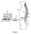
最初に図1に移ると、例示的なSCM神経変調システム10は、一般的に、1つ又はそれよりも多くの(この場合に、2つの)埋込可能変調リード12と、埋込可能パルス発生器(IPG)14と、外部リモートコントローラ(RC)16と、臨床医のプログラマー(CP)18と、外部試行変調器(ETM)20と、外部充電器22とを含む。
Turning first to FIG. 1, an exemplary SCM neuromodulation system 10 generally includes one or more (in this case, two) implantable modulation leads 12 and implantable pulses. It includes a generator (IPG) 14, an external remote controller (RC) 16, a clinician programmer (CP) 18, an external trial modulator (ETM) 20, and an
IPG14は、1つ又はそれよりも多くの経皮リード延長部24を通してアレイに配置された複数の電極26を担持する変調リード12に物理的に接続される。図示の実施形態において、変調リード12は経皮リードであり、この目的に対して、電極26を変調リード12に沿って一列に配置することができる。代替実施形態において、電極26は、単一パドルリード上に2次元パターンに配置することができる。下記でより詳細に説明するように、IPG14は、変調パラメータセットに従って電気変調エネルギをパルス電気波形の形態(すなわち、電気パルスの時系列)で電極アレイ26に送出するパルス発生回路を含む。
The
ETM20は、経皮リード延長部28及び外部ケーブル30を通して変調リード12に物理的に接続することができる。IPG14に類似のパルス発生回路を有するETM20も、変調パラメータセットに従って電気変調エネルギをパルス電気波形の形態で電極アレイ26に送出する。ETM20とIPG14の間の主な相違点は、ETM20が、与えられることになる刺激の応答性を変調リード12が埋め込まれた後及びIPG14の埋め込みの前に試験するために試行ベースで使用される非埋込可能デバイスである点である。従って、IPG14に関して説明するあらゆる機能は、ETM20に関しても同じく実施することができる。
The
RC16は、双方向RF通信リンク32を通してETM20を遠隔測定的に制御するために使用することができる。IPG14及び変調リード12が埋め込まれた状態で、双方向RF通信リンク34を通してIPG14を遠隔測定的に制御するためにRC16を使用することができる。そのような制御は、IPG14を起動又は停止し、異なる変調パラメータセットを用いてプログラムすることを可能にする。IPG14は、プログラミングされた変調パラメータを修正し、IPG14によって出力される電気変調エネルギの特性を能動的に制御するように作動させることができる。下記でより詳細に説明するように、CP18は、手術室及び予後の診療においてIPG14及びETM20をプログラムするための詳細な変調パラメータを臨床医に提供する。
The
CP18は、IR通信リンク36を介し、RC16を通してIPG14又はETM20と間接的に通信することによって上述の機能を実施することができる。これに代えて、CP18は、RF通信リンク(図示せず)を通してIPG14又はETM20と直接に通信することができる。変調パラメータを独立モードにおける(すなわち、CP18の補助なしでの)RC16の作動によって後に修正することができるように、CP18によって与えられる臨床医が詳述した変調パラメータは、RC16をプログラムするためにも使用される。
The
外部充電器22は、誘導リンク38を通してIPG14を経皮的に充電するのに使用される携帯デバイスである。簡潔化の目的で、外部充電器22の詳細に関しては、本明細書では記載しない。IPG14がプログラムされ、かつその電源が外部充電器22によって充電されるか又は他に補充された状態で、IPG14は、RC16又はCP18が存在しない状態でもプログラムされた通りに機能することができる。
The
簡潔化の目的で、RC16、CP18、ETM20、及び外部充電器22の詳細に関しては、本明細書では記載しない。これらのデバイスの例示的実施形態の詳細は、米国特許第6,895,280号明細書に開示されている。
For the sake of brevity, the details of RC16, CP18, ETM20, and
図2に示すように、変調リード(又はリード)12は、患者40の脊椎42内に埋め込まれる。変調リード12の好ましい配置は、刺激される脊髄区域に隣接する硬膜に隣接し、すなわち、硬膜の近く又はその上に静置される。神経変調リード12は、慢性疼痛の場所及び分布に依存する椎骨位置に位置付けられることになる。例えば、慢性疼痛が腰背部又は脚部に存在する場合に、変調リード12を中位から低位の胸領域(例えば、T9〜12椎骨高さ)に設置することができる。変調リード12が脊椎42を出る場所の近くでの空間の欠如に起因して、IPG14は、一般的に、腹部又は臀部の上方のいずれかに手術で生成されたポケット内に埋め込まれる。IPG14は、当然ながら患者の身体の他の場所に埋め込むことができる。リード延長部24は、電極リード12の出口点から離してIPG14を設置するのを容易にする。図2に示すように、CP18は、RC16を通してIPG14と通信する。
As shown in FIG. 2, the modulation lead (or lead) 12 is implanted in the
ここで図3を参照して、変調リード12及びIPG14の特徴を簡単に以下に説明する。変調リードの一方12(1)は、8つの電極26(E1〜E8とラベル付けした)を有し、他方の変調リード12(2)は、8つの電極26(E9〜E16とラベル付けした)を有する。リード及び電極の実際の個数及び形状は、当然ながら意図する用途に従って異なることになる。IPG14は、電子機器及び他の構成要素(下記でより詳細に説明する)を含むための外側ケース44と、電極26を外側ケース40内の電子機器に電気結合する方式で変調リード12の近位端が嵌合するコネクタ46とを含む。外側ケース44は、チタンのような導電性生体適合材料からなり、体内電子機器を身体組織及び流体から保護する密封区画を形成する。一部の場合に、外側ケース40は、電極として機能することができる。
Here, the features of the
下記でより詳細に説明するように、IPG14は、バッテリと、IPG14にプログラムされた変調パラメータセットに従って電気変調エネルギを1つ又はそれよりも多くの電気パルス列の形態で電極アレイ26に送出するパルス発生回路とを含む。そのような変調パラメータは、アノード(正)、カソード(負)として活性化され、かつオフ(ゼロ)される電極を定める電極組合せと、各電極に割り当てられた変調エネルギの百分率(分割電極構成)と、パルス振幅(IPG14が電極アレイ26に定電流又は定電圧のいずれを供給するかに依存してミリアンペア又はボルトで測定)、パルス持続時間(マイクロ秒で測定)、パルス繰返し数(パルス毎秒で測定)、中間相(二相パルスの2つの相の間でマイクロ秒で測定)、及びバースト繰返し数(変調作動(オン)持続時間X及び変調オフ持続時間Yとして測定される)を定める電気パルスパラメータとを含むことができる。
As described in more detail below, the
電気変調は、一方をIPGケース44とすることができる2つ(又はそれよりも多く)の活性化電極間で発生することになる。変調エネルギは、組織に単極方式又は多重極(例えば、二重極、三重極等)方式で伝達することができる。単極変調は、リード電極26のうちの選択される1つがIPG14のケースと共に活性化され、それによって変調エネルギがこの選択される電極26とケースの間で伝達される場合に発生する。二重極変調は、リード電極26のうちの2つがアノード及びカソードとして活性化され、それによって変調エネルギが選択されるこれらの電極26の間で伝達される場合に発生する。例えば、第2のリード12(1)上の電極E11がカソードとして活性化されると同時に第1のリード12(1)上の電極E3をアノードとして活性化することができる。三重極変調は、リード電極26のうちの3つが、2つがアノードとして、残りの1つがカソードとして、又は2つがカソードとして、残りの1つがアノードとして活性化される場合に発生する。例えば、第2のリード12上の電極E12がカソードとして活性化されると同時に第1のリード12上の電極E4及びE5をアノードとして活性化することができる。
Electrical modulation will occur between two (or more) activation electrodes, one of which can be the
変調エネルギは、指定された電極群の間で単相電気エネルギ又は多相電気エネルギとして送出することができる。図4に示すように、単相電気エネルギは、全て負のパルス(カソード)又はこれに代えて全て正のパルス(アノード)のいずれかを含む電気パルス列の形態を取る。 Modulated energy can be delivered as single phase electrical energy or multiphase electrical energy between designated groups of electrodes. As shown in FIG. 4, single-phase electrical energy takes the form of an electrical pulse train that includes either all negative pulses (cathode) or alternatively all positive pulses (anode).
多相電気エネルギは、正と負の間で交替する一連のパルスを含む。例えば、図5a及び図5bに例示するように、多相電気エネルギは、カソード(負)変調パルス(第1の相中の)と、組織を通る直流電荷移動を防止し、それによって電極の劣化及び細胞の創傷を回避するために変調パルスの後に生成されるアノード(正)電荷回収パルス(第2の相中の)とを各々が含む一連の2相パルスを含むことができる。すなわち、電荷は、変調期間(変調パルスの長さ)中に電極における電流を通じて電極−組織インタフェースを通して搬送され、次いで、再充電期間(電荷回収パルスの長さ)中に同じ電極における反対に分極された電流を通じて電極−組織インタフェースから引き戻される。 Polyphase electrical energy includes a series of pulses that alternate between positive and negative. For example, as illustrated in FIGS. 5a and 5b, multiphase electrical energy prevents cathodic (negative) modulation pulses (in the first phase) and DC charge transfer through the tissue, thereby degrading the electrodes. And a series of biphasic pulses, each including an anodic (positive) charge recovery pulse (in the second phase) generated after the modulation pulse to avoid cell wounding. That is, charge is transported through the electrode-tissue interface through the current at the electrode during the modulation period (the length of the modulation pulse) and then oppositely polarized at the same electrode during the recharge period (the length of the charge recovery pulse). Pulled back from the electrode-tissue interface through the measured current.
第2の相は、電流を電流源又は電圧源によって電極を通して能動的に搬送する能動的電荷回収パルス(図5a)と、受動的電荷回収パルスとを有することができ、又は電流を回路に存在する結合容量から流れる電荷の再配分によって電極を通して受動的に搬送する受動的電荷回収パルス(図5b)を有することができる。能動的再充電を使用することにより、受動的再充電とは対照的に又は他に発生する可能性がある電荷不均衡を回避しながらより高速な再充電が可能になる。中間相の形態にある別の電気パルスパラメータは、2相パルスを構成するパルス間の期間(マイクロ秒で測定)を定めることができる。 The second phase can have an active charge recovery pulse (FIG. 5a) that actively carries the current through the electrode by a current source or voltage source and a passive charge recovery pulse, or the current is present in the circuit Passive charge recovery pulses (FIG. 5b) can be carried passively through the electrodes by redistribution of charge flowing from the coupling capacitance. The use of active recharging allows for faster recharging while avoiding charge imbalances that may occur in contrast to or otherwise from passive recharging. Another electrical pulse parameter in the form of an intermediate phase can define the period (measured in microseconds) between the pulses that make up the biphasic pulse.
本発明に対して重要な点として、SCMシステム10は、複数の個々の電気パルス列をそれぞれの複数のタイミングチャネルを通して共通の電極セットに同時に送出することができ、それによって電極の共通セットにおいて組合せ電気パルス列を提供する。この仕様目的のために、電気パルス列は、そのパルスのうちのいずれかが重なる場合は同時に搬送されるか、又は互いに対して交互配置される。好ましい方法では、個々のパルス列は、複数の電極から患者の組織を通して共通電極(又は複数の電極)にそれぞれ搬送される。好ましくは、治療を与えるために、共通電極(又は複数の電極)に隣接する組織は、組合せ電気パルス列によって治療効果的に変調(例えば、刺激)される。有利なことに、複数のタイミングチャネルを用いて電極の共通セットでの複数の電気パルス列を単一電気パルス列に組み合わせることにより、SCMシステム10が、そうでなければSCMシステム10内でのハードウエア制限に起因して単一タイミングチャネルを用いては生成することができない可能性がある電気パルス列を生成することが可能になる。 Significant to the present invention, the SCM system 10 can simultaneously deliver multiple individual electrical pulse trains through respective multiple timing channels to a common electrode set, thereby combining electric power in the common set of electrodes. Provide a pulse train. For this specification purpose, the electrical pulse trains are carried simultaneously if any of the pulses overlap or are interleaved with respect to each other. In a preferred method, individual pulse trains are each delivered from multiple electrodes through a patient's tissue to a common electrode (or multiple electrodes). Preferably, to provide therapy, the tissue adjacent to the common electrode (or electrodes) is therapeutically modulated (eg, stimulated) by the combined electrical pulse train. Advantageously, by using multiple timing channels to combine multiple electrical pulse trains with a common set of electrodes into a single electrical pulse train, the SCM system 10 would otherwise be hardware limited within the SCM system 10. This makes it possible to generate an electric pulse train that may not be generated using a single timing channel.
特に、SCMシステム10のハードウエアは、それぞれのタイミングチャネル内で搬送される個々のパルス列が、組合せ電気パルス列内で発生する場合がある特定の特性を有することを妨げる。従って、タイミングチャネルは、ある一定の特性を有する個々のパルス列が電極の共通セットに送出されることを妨げる場合があるが、そのような特性を有する組合せパルス列は、電極の共通セットに送出することができる。 In particular, the hardware of the SCM system 10 prevents the individual pulse trains carried in each timing channel from having certain characteristics that may occur within the combined electrical pulse train. Thus, a timing channel may prevent individual pulse trains having certain characteristics from being delivered to a common set of electrodes, but a combined pulse train having such properties may be delivered to a common set of electrodes. Can do.
例えば、特定の特性は、最大値を超えるパルス振幅とすることができ(すなわち、単一チャネル変調は、個々のパルス列の各々のパルス振幅が最大値を超えることができない点で限定される)、この場合に、組合せ電気パルス列は、最大値を超えるパルス振幅を有することができる。組合せ電気パルス列は、個々のパルス列の変調パルスを組合せパルス列が個々のパルス列のパルス振幅の和に等しくなるように互いに重ねることによって生成することができる。 For example, a particular characteristic can be a pulse amplitude that exceeds a maximum value (ie, single channel modulation is limited in that each pulse amplitude of an individual pulse train cannot exceed the maximum value), In this case, the combined electrical pulse train can have a pulse amplitude exceeding the maximum value. A combined electrical pulse train can be generated by superimposing modulated pulses of individual pulse trains on each other such that the combined pulse train is equal to the sum of the pulse amplitudes of the individual pulse trains.
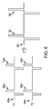
図6に示すように、2つの個々の電気パルス列60a及び60bは、それぞれ2つのタイミングチャネルT1及びT2内で電極の共通セット(例えば、電極E1)に送出され、電極の共通セットにおいて単一組合せ電気パルス列60を与える。図示の実施形態において、単一組合せ電気パルス列60は、それぞれの個々の電気パルス列60a及び60bの2相変調パルス62a及び62bを同時に電極の共通セットに送出することによって各々が提供される一連の2相パルス62を含む。図6に示すように、組合せパルス列60のパルス振幅は、個々のパルス列60a及び60bのいかなるパルス振幅よりも大きく、特にパルス列60aのパルス振幅とパルス列60bのパルス振幅との和に等しい。実際に、電極の共通セットに送出される電気パルス列のパルス振幅の大きさは増大する。
As shown in FIG. 6, two individual electrical pulse trains 60a and 60b are delivered to a common set of electrodes (eg, electrode E1) in two timing channels T1 and T2, respectively, and a single combination in the common set of electrodes. An
別の例として、特定の特性は、最大値を超えるパルス繰返し数とすることができ(すなわち、単一チャネル変調は、個々のパルス列の各々のパルス繰返し数が最大値を超えることができない点で限定される)、この場合に、組合せ電気パルス列は、最大値を超えるパルス繰返し数を有することができる。組合せ電気パルス列は、個々のパルス列の変調パルスを組合せパルス列が個々のパルス列のパルス繰返し数の和に等しいパルス繰返し数を有するように互いに交互配置することによって生成することができる。 As another example, a particular characteristic may be a pulse repetition rate that exceeds a maximum value (ie, single channel modulation is such that each pulse repetition rate of an individual pulse train cannot exceed the maximum value. In this case, the combined electrical pulse train can have a pulse repetition rate exceeding the maximum value. A combined electrical pulse train can be generated by interleaving modulated pulses of individual pulse trains with each other such that the combined pulse train has a pulse repetition rate equal to the sum of the pulse repetitions of the individual pulse trains.
図7に示すように、2つの個々の電気パルス列60a及び60bは、それぞれ2つのタイミングチャネルT1及びT2内で電極の共通セット(例えば、電極E1)に送出され、電極の共通セットにおいて単一組合せ電気パルス列60を与える。図示の実施形態において、単一組合せ電気パルス列60は、それぞれの個々の電気パルス列60a及び60bの2相変調パルス62a及び62bを同時に電極の共通セットに交互配置方式で送出することによって各々が提供される一連の2相パルス62を含む。図7に示すように、組合せパルス列60のパルス繰返し数は、個々のパルス列60a及び60bのいかなるパルス繰返し数よりも大きく、特にパルス列60aのパルス繰返し数とパルス列60bのパルス繰返し数との和に等しい。図示の実施形態において、個々のパルス列60aのパルス繰返し数と個々のパルス列60bのパルス繰返し数とは互いに等しく、従って、組合せパルス列60のパルス繰返し数は均一であり、かつパルス列60a及び60bの各々のパルス繰返し数の2倍である。
As shown in FIG. 7, two individual electrical pulse trains 60a and 60b are delivered to a common set of electrodes (eg, electrode E1) in two timing channels T1 and T2, respectively, and a single combination in the common set of electrodes. An
更に別の例として、特定の特性は、変化するパルス繰返し数とすることができ(すなわち、単一チャネル変調は、個々のパルス列の各々のパルス繰返し数が均一でなければならない点で限定される)、この場合に、組合せ電気パルス列は、変化するパルス繰返し数を有することができる。組合せ電気パルス列は、個々のパルス列の変調パルスを組合せパルス列が変化するパルス繰返し数を有するように互いに交互配置することによって生成することができる。 As yet another example, a particular characteristic can be a varying pulse repetition rate (ie, single channel modulation is limited in that each pulse repetition rate of an individual pulse train must be uniform). In this case, the combined electrical pulse train can have a variable pulse repetition rate. A combined electrical pulse train can be generated by interleaving the modulated pulses of individual pulse trains with each other such that the combined pulse train has a pulse repetition rate that varies.
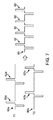
図8に示すように、4つの個々の電気パルス列60a〜60dは、それぞれ4つのタイミングチャネルT1〜T4内で電極の共通セット(例えば、電極E1)に送出され、電極の共通セットにおいて単一組合せ電気パルス列60を与える。図示の実施形態において、単一組合せ電気パルス列60は、それぞれの個々の電気パルス列60a〜60dの単相変調パルス62a〜62dを電極の共通セットに交互配置方式で送出することによって各々が提供される一連の単相変調パルス62を含む。図8に示すように、組合せパルス列60のパルス繰返し数は、比較的高いレベルと比較的低いレベルとの間で変化する。
As shown in FIG. 8, four individual electrical pulse trains 60a-60d are delivered to a common set of electrodes (eg, electrode E1) within four timing channels T1-T4, respectively, and a single combination in the common set of electrodes. An
更に別の例として、特定の特性は、異なるパルス繰返し数を有する連続出現(バースト)パターンのシーケンスとすることができ(すなわち、単一チャネル変調は、個々のパルス列の各々が固定のパルス繰返し数で連続出現(バースト)をオン及びオフすることしかできない点で限定される)、この場合に、組合せ電気パルス列は、変化するパルス繰返し数を有する一連のバーストパターンを有することができる。この場合に、電気パルス列を同時に搬送するのではなく、図6〜図8に示すように、電気パルス列は、連続的にバーストをオン及びオフさせることができ、異なるパルス繰返し数を用いた複数のバーストパターンを有する組合せ電気パルス列を与える。 As yet another example, the particular characteristic can be a sequence of consecutive occurrence (burst) patterns with different pulse repetition rates (ie, single channel modulation is a pulse repetition rate where each individual pulse train has a fixed pulse repetition rate). In this case, the combined electrical pulse train can have a series of burst patterns with varying pulse repetition rates. In this case, instead of carrying the electric pulse train at the same time, as shown in FIGS. 6 to 8, the electric pulse train can continuously turn on and off the burst, and a plurality of different pulse repetition rates can be used. A combined electrical pulse train having a burst pattern is provided.
図9に示すように、4つの個々の電気パルス列60a〜60dは、それぞれ4つのタイミングチャネルT1〜T4内で電極の共通セット(例えば、電極E1)に送出され、電極の共通セットにおいて単一組合せ電気パルス列60を与える。図示の実施形態において、単一組合せ電気パルス列60は、それぞれの個々の電気パルス列60a〜60dの変調パルス62a〜62dのバーストを電極の共通セットに連続して送出することによって各々が提供される一連のパルス62を含む。図9に示すように、組合せパルス列60は、第1のパルス列60aから得られた第1のバーストパターン62a、次いで、第2のパルス列60bから得られた第2のバーストパターン62b、更に第3のパルス列60cから得られた第3のバーストパターン62c、最後に第4のパルス列60dから得られた第4のバーストパターン62dを含む。
As shown in FIG. 9, four individual electrical pulse trains 60a-60d are delivered to a common set of electrodes (eg, electrode E1) within four timing channels T1-T4, respectively, and a single combination in the common set of electrodes. An
次いで図10に移り、ここでIPG14の主な内部構成要素を以下に説明する。IPG14は、データバス104を通じた制御論理回路102の制御下で指定されたパルス振幅、パルス繰返し数、パルス幅、パルス形状、及びバースト繰返し数を有する定められたパルス波形に従って電気変調エネルギを発生させるように構成された変調出力回路100を含む。電気波形のパルス繰返し数及びパルス幅の制御は、適切な分解能、例えば、10μsを有することができるタイマ論理回路106によって容易にされる。変調出力回路100によって発生させた変調エネルギは、コンデンサーC1〜C16を通して電極26に対応する電気端子108に出力される。アナログ出力回路100は、指定された既知のアンペア数の変調パルスを電極26に又はそこから供給するための独立制御電流源、又は指定された既知の電圧の変調パルスを電極26に供給するための独立制御電圧源のいずれかを含むことができる。
Turning now to FIG. 10, the main internal components of the
N個の電極のうちのいずれも、k個までの可能な群又はタイミング「チャネル」に割り当てることができる。一実施形態において、kは、4に等しいとすることができる。タイミングチャネルは、刺激される組織内に電界を生成する上でどの電極が同期して電流を流出させるか又は流入させるように選択されているかを識別する。チャネル上の電極の振幅及び極性は、例えば、RC16によって制御される通りに変更することができる。他の可能なプログラマブルな特徴の中でも取りわけ、与えられたチャネル上の電極に対する電極極性、振幅、パルス繰返し数、パルス持続時間、中間相、バースト繰返し数、及びバースト負荷サイクルを含む変調パラメータを設定するのに、CP18内の外部プログラミングソフトウエアが典型的に使用される。
Any of the N electrodes can be assigned to up to k possible groups or timing “channels”. In one embodiment, k may be equal to 4. The timing channel identifies which electrodes are selected to flow out or flow in synchronously in generating an electric field in the stimulated tissue. The amplitude and polarity of the electrodes on the channel can be changed, for example, as controlled by RC16. Set modulation parameters including electrode polarity, amplitude, pulse repetition rate, pulse duration, intermediate phase, burst repetition rate, and burst duty cycle for electrodes on a given channel, among other possible programmable features To do this, external programming software within
k個のチャネルのうちのいずれかにおいて、N個のプログラマブル電極は、正(電流を流出させる)極性、負(電流を流入させる)極性、又はオフ(無電流)極性を有するようにプログラムすることができる。更に、N個の電極の各々は、例えば、2つ又はそれよりも多くの電極接点が同時に電流を流出/流入させるようにグループ分けされた多重極(例えば、二重極)モードで作動させることができる。これに代えて、N個の電極の各々は、例えば、チャネルに関連付けられた電極接点がカソード(負)として構成され、ケース電極(すなわち、IPGケース)がアノード(正)として構成される単極モードで作動させることができる。 In any of the k channels, the N programmable electrodes are programmed to have a positive (current flowing out) polarity, a negative (current flowing in) polarity, or an off (no current) polarity. Can do. In addition, each of the N electrodes may be operated in a multipole (eg, double pole) mode, for example, grouped such that two or more electrode contacts simultaneously drain / inflow current. Can do. Instead, each of the N electrodes is, for example, a single electrode in which the electrode contact associated with the channel is configured as the cathode (negative) and the case electrode (ie, the IPG case) is configured as the anode (positive) Can be operated in mode.
更に、与えられた電極から流出するか又はそこに流入する電流パルスの振幅は、いくつかの離散電流レベル、例えば、0mAから10mAの間で0.1mA刻みのレベルのうちの1つにプログラムすることができる。また、電流パルスのパルス持続時間は、好ましくは、好ましい増分で、例えば、0ミリ秒(ms)から1ミリ秒(ms)までを10マイクロ秒(μs)の増分で調節可能である。同様に、パルス繰返し数は、好ましくは、許容限度の範囲で、例えば、0パルス毎秒(pps)から1000パルス毎秒(pps)の範囲で調節可能である。プログラマブルな他の特徴は、緩慢な立ち上がり/立ち下がり、バースト変調サイクル(X時間にわたってオン、Y時間にわたってオフ)、中間相、及び開ループ又は閉ループの感知モードを含むことができる。 In addition, the amplitude of the current pulse flowing out of or entering a given electrode is programmed to one of several discrete current levels, for example between 0 mA and 10 mA in steps of 0.1 mA. be able to. Also, the pulse duration of the current pulse is preferably adjustable in preferred increments, for example from 0 milliseconds (ms) to 1 millisecond (ms) in 10 microsecond (μs) increments. Similarly, the pulse repetition rate is preferably adjustable within a tolerance range, for example, from 0 pulse per second (pps) to 1000 pulses per second (pps). Other programmable features can include slow rise / fall, burst modulation cycles (on for X time, off for Y time), mesophase, and open loop or closed loop sensing modes.
規定の振幅及び持続時間の変調パルスを発生させるこの同じ機能を実施するための適切な出力回路の代替実施形態を含むこのアナログ出力回路100の作動は、米国特許第6,516,227号明細書及び第6,993,384号明細書により完全に記載されている。
The operation of this
IPG14は、IPG14を通した様々なノード又は他の点112のステータス、例えば、電源電圧、温度、及びバッテリ電圧などをモニタするためのモニタ回路110を更に含む。IPG14は、データバス116を通して制御論理部を制御し、かつデータバス118を通してモニタ回路110からステータスデータを取得するマイクロコントローラ(μC)114の形態にある処理回路を更に含む。更に、IPG14は、タイマ論理部108を制御する。IPG14は、マイクロコントローラ114に結合されたメモリ120と、発振器及びクロック回路122とを更に含む。この場合に、マイクロコントローラ114は、メモリ120、並びに発振器及びクロック回路122との組合せで、メモリ118に格納された適切なプログラムに従ってプログラム機能を実施するマイクロプロセッサシステムを構成する。これに代えて、一部の用途に対して、マイクロプロセッサシステムによって与えられる機能は、適切な状態機械によって実施することができる。
The
すなわち、マイクロコントローラ114は、マイクロコントローラ114がメモリ120に格納された選択された作動プログラム及び変調パラメータに従ってIPG14の作動を制御することを可能にする必要な制御信号及びステータス信号を発生させる。IPG14の作動を制御するのに、マイクロコントローラ114は、変調出力回路100を制御論理部102及びタイマ論理部106との組合せに用いて、電極26において電気パルス列を個々に生成することができ、それによって単極ケース電極を含む他の電極26に対して各電極26を対合又はグループ分けすることを可能にする。メモリ118内に格納された変調パラメータに従ってマイクロコントローラ114は、極性、振幅、繰返し数、パルス持続時間、及び変調パルスが供給される際に通るタイミングチャネルを制御することができる。
That is, the
すなわち、マイクロコントローラ114の制御下で、変調出力回路100は、各々が図4、図5a、及び図5bに示すように2相パルスを含むk個の個々の電気パルス列をそれぞれk個のタイミングチャネル内で電気端子106に出力するように構成されることを認めることができる。IPG14では、各々が4つのタイミングチャネルを有する4つまでのシミュレーションプログラムをメモリ120に格納することができる。従って、各変調プログラムは、4つのそれぞれのタイミングチャネルに対して4つの変調パラメータセットを定める。当然ながら、IPG14は、4つよりも少ないか又は多い変調プログラム、及び各変調プログラムに対して4つよりも少ないか又は多いタイミングチャネルを有することができる。重要な点として、マイクロコントローラ114は、複数の電気パルス列を電気端子108の共通セット(従って、電極26の共通セット)に送出し、電気端子108の共通セットにおいて単一電気パルス列を発生させる方式、例えば、図6〜図9に例示した技術において説明した方式で変調出力回路100を制御することができる。マイクロコントローラ114の機能は、ソフトウエアに実施することができるので、これらの技術は、既存のハードウエア設計を修正することなくIPG14内に容易に実施することができる。
That is, under the control of the
IPG14は、RC16(図2に示す)から適切な変調搬送波信号でプログラミングデータ(例えば、作動プログラム及び/又は変調パラメータ)を受信するための交流(AC)受信コイル124と、後でメモリ120の内部又はIPG14を通して分散された他のメモリ要素(図示せず)内に格納されたプログラミングデータを回復するためにAC受信コイル124を通して受信された搬送波信号を復調するための充電及び前方遠隔測定(テレメトリ)回路126とを更に含む。
The
IPG14は、モニタ回路110によって感知された情報データをRC16に送るための後方遠隔測定(テレメトリ)回路128及び交流(AC)送信コイル130を更に含む。IPG14の後方テレメトリ回路の特徴は、そのステータスを検査することも可能にする。例えば、RC16がIPG14とのプログラミング作業を開始するときに、外部プログラマーが、再充電するための推定時間を計算することができるように、バッテリの容量がテレメトリされる。現在の刺激パラメータに加えられたいずれの変更も後方テレメトリ回路を通して確認され、それによってそのような変更が正しく受信され、埋め込みシステム内に実施されることを確実にする。更に、RC16による照会時に、IPG14内に格納された全てのプログラマブル設定をRC16にアップロードすることができる。有意なことに、後方テレメトリ回路の特徴は、メモリ120内にそれまでに格納された生の又は処理された電気パラメータデータ(又は他のパラメータデータ)をIPG14からRC16にダウンロードすることを可能にし、これらの情報を患者の身体活動を追跡するために使用することができる。
The
IPG14は、IPG14に作動電力を供給するための再充電可能電源132及び電力回路134を更に含む。再充電可能電源132は、例えば、リチウムイオンバッテリ又はリチウムイオンポリマーバッテリを含むことができる。再充電可能バッテリ132は、電力回路134に未調整電圧を供給する。電力回路134は、次に、IPG14内に位置付けられた様々な回路による必要性に応じて、一部が調整され、一部が調整されない様々な電圧136を発生させる。再充電可能電源132は、AC受信コイル134によって受信される整流されたAC電力(又は他の手段、例えば、「インバータ回路」としても公知の有効なACからDCへのコンバータ回路を通してAC電力から変換されたDC電力)を用いて再充電される。電源132を再充電するために、AC磁場を生成する外部充電器(図示せず)が、埋め込まれたIPG14を覆う患者の皮膚に接して又は他に隣接して配置される。外部充電器によって放出されるAC磁場は、AC受信コイル134内にAC電流を誘導する。充電及び前方テレメトリ回路136は、AC電流を整流し、電源132を充電するのに使用されるDC電流を生成する。AC受信コイル134を通信(例えば、プログラミングデータ及び制御データ)を無線受信するため及び外部デバイスからエネルギを充電するための両方に使用されるものとして記述したが、AC受信コイル134は、充電専用コイルとして配置することができ、一方、コイル130のような別のコイルは、双方向テレメトリに使用することができることを認めなければならない。
The
図10の図は機能的なものでしかなく、限定的であるように意図していないことに注意しなければならない。当業者は、本明細書に与えた説明を受けて、選択される電極群上に刺激電流又は刺激電圧を生成することだけではなく、活性化電極又は非活性化電極における電気パラメータデータを測定する機能も含む参照して記述した機能を実施する多くのタイプのIPG回路又は均等な回路を直ちに想起することができるはずである。 It should be noted that the diagram of FIG. 10 is only functional and is not intended to be limiting. Those skilled in the art, in accordance with the description provided herein, measure electrical parameter data at the activated or deactivated electrodes, as well as generating stimulation currents or stimulation voltages on selected groups of electrodes. It should be immediately possible to recall many types of IPG circuits or equivalent circuits that implement the functions described with reference, including functions.
上述のIPG及び他のIPGに関する追加の詳細は、米国特許第6,516,227号明細書、米国特許公開第2003/0139781号明細書、及び米国特許公開第2005/0267546号明細書に見出すことができる。SCMシステム10は、IPGではなく、変調リード12に接続した埋込可能受信機−刺激器(図示せず)をこれに代えて利用することができることに注意しなければならない。この場合に、埋め込まれた受信機に給電するための電源、例えば、バッテリ、並びに受信機−刺激器に命令する制御回路は、電磁リンクを通して受信機−刺激器に誘導結合された外部コントローラに含まれることになる。データ/電力信号は、埋め込まれた受信機−刺激器の上に配置されたケーブル接続の送信コイルから経皮的に結合される。埋め込まれた受信機−刺激器は、信号を受信し、制御信号に従って変調を発生させる。
Additional details regarding the above IPGs and other IPGs can be found in US Pat. No. 6,516,227, US Patent Publication No. 2003/0139881, and US Patent Publication No. 2005/0267546. Can do. It should be noted that the SCM system 10 can instead utilize an implantable receiver-stimulator (not shown) connected to the
上記に簡単に解説したように、RC16及び/又はCP18は、電気パルス列をその間で送出することになる特定の電極26を含む変調パラメータを指定するための入力をユーザから受け入れるように構成されたユーザインタフェースを含む。ユーザは、単一タイミングチャネルを用いては達成することができないが、複数のタイミングチャネルを用いて達成することができる特定の特性を指定することができ、図6〜図9に関して記述したもののようなこの特定の特性を有する組合せ電気パルス列を提供する。
As briefly described above,
本発明の特定の実施形態を図示して記述したが、本発明をこれらの好ましい実施形態に限定するように意図していないことは理解されるであろう。更に、本発明の精神及び範囲から逸脱することなく様々な変形及び修正を加えることができることは当業者に明らかであろう。すなわち、本発明は、特許請求の範囲によって定められる本発明の精神及び範囲内に含まれる場合がある代替物、修正物、及び均等物を網羅するように意図している。 While particular embodiments of the present invention have been illustrated and described, it will be understood that the invention is not intended to be limited to these preferred embodiments. In addition, it will be apparent to those skilled in the art that various modifications and variations can be made without departing from the spirit and scope of the invention. That is, the present invention is intended to cover alternatives, modifications, and equivalents that may be included within the spirit and scope of the present invention as defined by the claims.
14 神経変調システム
100 変調出力回路
108 電極
114 制御回路
14
Claims (18)
複数の個々の電気パルス列を複数のタイミングチャネル内で前記複数の電気端子にそれぞれ出力するように構成された変調出力回路であって、前記タイミングチャネルの各々がそれぞれの電気パルスが特定の特性を有することを妨げている、前記変調出力回路と、
複数の前記パルス列を前記電気端子の共通セットに出力し、それによって該電気端子の共通セットで前記特定の特性を有する組合せ電気パルス列を生成する方式で前記変調出力回路を制御するように構成された制御回路と、
を含むことを特徴とする神経変調システム。 A plurality of electrical terminals configured to be respectively coupled to the plurality of electrodes;
A modulation output circuit configured to output a plurality of individual electric pulse trains to the plurality of electric terminals in a plurality of timing channels, respectively, wherein each of the timing channels has a specific characteristic The modulation output circuit,
The modulation output circuit is configured to control the modulation output circuit in a manner that outputs the plurality of pulse trains to a common set of the electrical terminals, thereby generating a combined electrical pulse train having the specific characteristics with the common set of electrical terminals. A control circuit;
A neuromodulation system comprising:
前記制御回路は、前記刺激プログラムの各々に対して前記複数のタイミングチャネルをプログラムするように構成されている、
ことを特徴とする請求項1に記載の神経変調システム。 Further comprising a memory configured to store a plurality of stimulation programs;
The control circuit is configured to program the plurality of timing channels for each of the stimulation programs;
The neuromodulation system according to claim 1.
前記患者内に埋め込まれた電極の共通セットに複数のタイミングチャネルで複数の電気パルス列をそれぞれ送出し、それによって該電気端子の該共通セットで組合せ電気パルス列を生成して該患者に前記治療を与える段階、
を含むことを特徴とする方法。 A method of giving treatment to a patient,
Delivering a plurality of electrical pulse trains in multiple timing channels, respectively, to a common set of electrodes implanted within the patient, thereby generating a combined electrical pulse train at the common set of electrical terminals to provide the treatment to the patient Stage,
A method comprising the steps of:
Applications Claiming Priority (3)
| Application Number | Priority Date | Filing Date | Title |
|---|---|---|---|
| US201361768286P | 2013-02-22 | 2013-02-22 | |
| US61/768,286 | 2013-02-22 | ||
| PCT/US2014/017777 WO2014130858A1 (en) | 2013-02-22 | 2014-02-21 | Multi-channel neuromodulation system with means for combining pulse trains |
Publications (2)
| Publication Number | Publication Date |
|---|---|
| JP2016507334A true JP2016507334A (en) | 2016-03-10 |
| JP2016507334A5 JP2016507334A5 (en) | 2017-03-16 |
Family
ID=50240048
Family Applications (1)
| Application Number | Title | Priority Date | Filing Date |
|---|---|---|---|
| JP2015559010A Pending JP2016507334A (en) | 2013-02-22 | 2014-02-21 | Multi-channel neuromodulation system with means for combining pulse trains |
Country Status (6)
| Country | Link |
|---|---|
| US (3) | US9138582B2 (en) |
| EP (1) | EP2958618B1 (en) |
| JP (1) | JP2016507334A (en) |
| CN (1) | CN105163801B (en) |
| AU (1) | AU2014218709B2 (en) |
| WO (1) | WO2014130858A1 (en) |
Cited By (3)
| Publication number | Priority date | Publication date | Assignee | Title |
|---|---|---|---|---|
| US9981134B2 (en) | 2013-02-22 | 2018-05-29 | Boston Scientific Neuromodulation Corporation | Multi-channel neuromodulation system having frequency modulation stimulation |
| CN109069829A (en) * | 2016-03-16 | 2018-12-21 | 于利奇研究中心有限公司 | Equipment for the neural stimulation that effectively intrusive and amplitude is modulated |
| WO2022209599A1 (en) * | 2021-03-29 | 2022-10-06 | 株式会社Mtg | Muscle electrical stimulation program and electrical stimulation device |
Families Citing this family (63)
| Publication number | Priority date | Publication date | Assignee | Title |
|---|---|---|---|---|
| US7783353B2 (en) | 2003-12-24 | 2010-08-24 | Cardiac Pacemakers, Inc. | Automatic neural stimulation modulation based on activity and circadian rhythm |
| ES2602989T3 (en) | 2007-07-20 | 2017-02-23 | Boston Scientific Neuromodulation Corporation | Stimulation system to control the order of neuronal recruitment and the clinical effect |
| US11376435B2 (en) | 2007-07-20 | 2022-07-05 | Boston Scientific Neuromodulation Corporation | System and method for shaped phased current delivery |
| WO2013111137A2 (en) | 2012-01-26 | 2013-08-01 | Rainbow Medical Ltd. | Wireless neurqstimulatqrs |
| US10814131B2 (en) | 2012-11-26 | 2020-10-27 | Thync Global, Inc. | Apparatuses and methods for neuromodulation |
| US10537703B2 (en) | 2012-11-26 | 2020-01-21 | Thync Global, Inc. | Systems and methods for transdermal electrical stimulation to improve sleep |
| WO2014087337A1 (en) | 2012-12-06 | 2014-06-12 | Bluewind Medical Ltd. | Delivery of implantable neurostimulators |
| US9174053B2 (en) | 2013-03-08 | 2015-11-03 | Boston Scientific Neuromodulation Corporation | Neuromodulation using modulated pulse train |
| US10293161B2 (en) | 2013-06-29 | 2019-05-21 | Thync Global, Inc. | Apparatuses and methods for transdermal electrical stimulation of nerves to modify or induce a cognitive state |
| CN111569263B (en) * | 2013-12-23 | 2024-04-26 | 脑深部创新有限责任公司 | Programming system for deep brain stimulator system |
| EP3110497A4 (en) | 2014-02-27 | 2018-12-05 | Cerevast Medical Inc. | Methods and apparatuses for user control of neurostimulation |
| WO2016004230A1 (en) | 2014-07-03 | 2016-01-07 | Boston Scientific Neuromodulation Corporation | Neurostimulation system with flexible patterning and waveforms |
| US9956404B2 (en) | 2014-11-19 | 2018-05-01 | Medtronic, Inc. | Electrical stimulation to inhibit bladder and/or bowel contraction |
| CN104888346B (en) * | 2014-12-21 | 2020-10-13 | 徐志强 | Method and device for performing nerve stimulation on coma brain |
| US10426945B2 (en) | 2015-01-04 | 2019-10-01 | Thync Global, Inc. | Methods and apparatuses for transdermal stimulation of the outer ear |
| US11534608B2 (en) | 2015-01-04 | 2022-12-27 | Ist, Llc | Methods and apparatuses for transdermal stimulation of the outer ear |
| US10258788B2 (en) | 2015-01-05 | 2019-04-16 | Thync Global, Inc. | Electrodes having surface exclusions |
| US9962547B2 (en) | 2015-02-05 | 2018-05-08 | Stimgenics, Llc | Method and apparatus for multimodal electrical modulation of pain |
| AU2016235457B2 (en) | 2015-03-20 | 2021-01-07 | Medtronic Sg, Llc | Method and apparatus for multimodal electrical modulation of pain |
| US10675466B2 (en) | 2015-03-20 | 2020-06-09 | Stimgenics, Llc | Method and apparatus for multimodal electrical modulation of pain using composite electromagnetic fields |
| US10850102B2 (en) | 2015-03-20 | 2020-12-01 | Medtronic Sg, Llc | Method and apparatus for multimodal electrical modulation of pain |
| US11167139B2 (en) | 2015-03-20 | 2021-11-09 | Medtronic Sg, Llc | Method and apparatus for multi modal electrical modulation of pain using composite electromagnetic fields |
| WO2016191055A1 (en) | 2015-05-28 | 2016-12-01 | Boston Scientific Neuromodulation Corporation | Neuromodulation using stochastically-modulated stimulation parameters |
| WO2016196454A1 (en) | 2015-05-29 | 2016-12-08 | Cerevast Medical Inc. | Methods and apparatuses for transdermal electrical stimulation |
| WO2016196635A2 (en) | 2015-06-01 | 2016-12-08 | Cerevast Medical Inc. | Apparatuses and methods for neuromodulation |
| JP2018519968A (en) * | 2015-07-22 | 2018-07-26 | グローバス メディカル インコーポレイティッド | Implantable pulse generator for generating spinal stimulation signals for the human body |
| US10105540B2 (en) | 2015-11-09 | 2018-10-23 | Bluewind Medical Ltd. | Optimization of application of current |
| US10391313B2 (en) | 2015-12-04 | 2019-08-27 | Boston Scientific Neuromodulation Corporation | Systems and methods for the development of therapy paradigms for neurological treatments |
| US11083896B2 (en) | 2015-12-18 | 2021-08-10 | Medtronic, Inc. | High duty cycle electrical stimulation therapy |
| US9956405B2 (en) | 2015-12-18 | 2018-05-01 | Thyne Global, Inc. | Transdermal electrical stimulation at the neck to induce neuromodulation |
| WO2017106878A1 (en) | 2015-12-18 | 2017-06-22 | Thync Global, Inc. | Apparatuses and methods for transdermal electrical stimulation of nerves to modify or induce a cognitive state |
| US10646708B2 (en) | 2016-05-20 | 2020-05-12 | Thync Global, Inc. | Transdermal electrical stimulation at the neck |
| US10525268B2 (en) | 2016-08-23 | 2020-01-07 | Medtronic, Inc. | Delivery of independent interleaved programs to produce higher-frequency electrical stimulation therapy |
| JP6841405B2 (en) * | 2016-09-09 | 2021-03-10 | 国立研究開発法人情報通信研究機構 | Brain rhythm frequency modulator |
| US10569088B2 (en) | 2016-09-16 | 2020-02-25 | Medtronic, Inc. | Dorsal spinal column characterization with evoked potentials |
| US11219763B2 (en) | 2016-10-28 | 2022-01-11 | Medtronic, Inc. | High frequency stimulation using low frequency titration gauge |
| US10124178B2 (en) | 2016-11-23 | 2018-11-13 | Bluewind Medical Ltd. | Implant and delivery tool therefor |
| US11045650B2 (en) | 2016-12-06 | 2021-06-29 | Medtronic, Inc. | High frequency neurostimulation for pelvic symptom control |
| WO2018187734A1 (en) | 2017-04-07 | 2018-10-11 | Medtronic, Inc. | Complex variation of electrical stimulation therapy parameters |
| US20180345022A1 (en) * | 2017-06-02 | 2018-12-06 | Boston Scientific Neuromodulation Corporation | Enhanced Selectivity and Modulation in Coordinated Reset in Deep Brain Stimulation |
| US20180353764A1 (en) | 2017-06-13 | 2018-12-13 | Bluewind Medical Ltd. | Antenna configuration |
| DE20168827T1 (en) | 2017-06-30 | 2021-01-21 | Gtx Medical B.V. | NEUROMODULATION SYSTEM |
| WO2019074949A1 (en) | 2017-10-10 | 2019-04-18 | Medtronic, Inc. | Management of electrical stimulation therapy |
| US10737100B2 (en) * | 2017-11-28 | 2020-08-11 | Medtronic, Inc. | Scalable stimulation waveform scheduler |
| WO2019209969A1 (en) | 2018-04-24 | 2019-10-31 | Thync Global, Inc. | Streamlined and pre-set neuromodulators |
| AU2019288752A1 (en) | 2018-06-21 | 2021-02-18 | Medtronic, Inc. | ECAP based control of electrical stimulation therapy |
| CN112351814A (en) | 2018-06-21 | 2021-02-09 | 美敦力公司 | ECAP-based control of electrical stimulation therapy |
| EP3653256B1 (en) | 2018-11-13 | 2022-03-30 | ONWARD Medical N.V. | Control system for movement reconstruction and/or restoration for a patient |
| DE18205817T1 (en) | 2018-11-13 | 2020-12-24 | Gtx Medical B.V. | SENSOR IN CLOTHING OF LIMBS OR FOOTWEAR |
| EP3695878B1 (en) | 2019-02-12 | 2023-04-19 | ONWARD Medical N.V. | A system for neuromodulation |
| US11918811B2 (en) | 2019-05-06 | 2024-03-05 | Medtronic Sg, Llc | Method and apparatus for multi modal or multiplexed electrical modulation of pain using composite electromagnetic fields |
| EP3738644B1 (en) * | 2019-05-13 | 2022-11-16 | ONWARD Medical N.V. | Method and system for providing multi-channel and/or variable neurostimulation |
| US11931582B2 (en) | 2019-10-25 | 2024-03-19 | Medtronic, Inc. | Managing transient overstimulation based on ECAPs |
| US11547855B2 (en) | 2019-10-25 | 2023-01-10 | Medtronic, Inc. | ECAP sensing for high frequency neurostimulation |
| EP3827871A1 (en) | 2019-11-27 | 2021-06-02 | ONWARD Medical B.V. | Neuromodulation system |
| US11260231B2 (en) | 2020-01-24 | 2022-03-01 | Medtronic, Inc. | Electrical stimulation modulation |
| US11426588B2 (en) | 2020-04-22 | 2022-08-30 | Advanced Neuromodulation Systems, Inc. | Systems and methods for arbitrary current waveform generation |
| US11478644B2 (en) | 2020-04-22 | 2022-10-25 | Advanced Neuromodulation Systems, Inc. | Systems and methods for DC protection in implantable pulse generators |
| US11857793B2 (en) | 2020-06-10 | 2024-01-02 | Medtronic, Inc. | Managing storage of sensed information |
| US11707626B2 (en) | 2020-09-02 | 2023-07-25 | Medtronic, Inc. | Analyzing ECAP signals |
| US11896828B2 (en) | 2020-10-30 | 2024-02-13 | Medtronic, Inc. | Implantable lead location using ECAP |
| US11400299B1 (en) | 2021-09-14 | 2022-08-02 | Rainbow Medical Ltd. | Flexible antenna for stimulator |
| WO2023244524A1 (en) * | 2022-06-17 | 2023-12-21 | Boston Scientific Neuromodulation Corporation | System for dithering neurostimulation parameters |
Citations (3)
| Publication number | Priority date | Publication date | Assignee | Title |
|---|---|---|---|---|
| JP2010527675A (en) * | 2007-05-22 | 2010-08-19 | スティーブン ギルビー,アイヴァー | Array stimulator |
| US20110125223A1 (en) * | 2009-11-23 | 2011-05-26 | Boston Scientific Neuromodulation Corporation | Neurostimulation system and method for compounding current to minimize current sources |
| WO2011082071A1 (en) * | 2009-12-30 | 2011-07-07 | Boston Scientific Neuromodulation Corporation | System for independently operating multiple neurostimulation channels |
Family Cites Families (9)
| Publication number | Priority date | Publication date | Assignee | Title |
|---|---|---|---|---|
| US6516227B1 (en) | 1999-07-27 | 2003-02-04 | Advanced Bionics Corporation | Rechargeable spinal cord stimulator system |
| US6993384B2 (en) | 2001-12-04 | 2006-01-31 | Advanced Bionics Corporation | Apparatus and method for determining the relative position and orientation of neurostimulation leads |
| US7539538B2 (en) | 2004-05-28 | 2009-05-26 | Boston Science Neuromodulation Corporation | Low power loss current digital-to-analog converter used in an implantable pulse generator |
| US8788044B2 (en) * | 2005-01-21 | 2014-07-22 | Michael Sasha John | Systems and methods for tissue stimulation in medical treatment |
| US20060259078A1 (en) * | 2005-05-16 | 2006-11-16 | Imad Libbus | Method and apparatus for electronically switching electrode configuration |
| US8583250B2 (en) * | 2008-04-29 | 2013-11-12 | Medtronic, Inc. | Therapy program modification based on an energy threshold |
| US8688222B2 (en) * | 2009-02-05 | 2014-04-01 | Cochlear Limited | Stimulus timing for a stimulating medical device |
| EP2756864B1 (en) | 2009-04-22 | 2023-03-15 | Nevro Corporation | Spinal cord modulation systems for inducing paresthetic and anesthetic effects |
| CN105163801B (en) | 2013-02-22 | 2017-11-07 | 波士顿科学神经调制公司 | Multi-channel nerve modulating system with the device for assembled pulse string |
-
2014
- 2014-02-21 CN CN201480023455.3A patent/CN105163801B/en not_active Expired - Fee Related
- 2014-02-21 JP JP2015559010A patent/JP2016507334A/en active Pending
- 2014-02-21 US US14/186,885 patent/US9138582B2/en active Active
- 2014-02-21 EP EP14709103.7A patent/EP2958618B1/en active Active
- 2014-02-21 AU AU2014218709A patent/AU2014218709B2/en active Active
- 2014-02-21 WO PCT/US2014/017777 patent/WO2014130858A1/en active Application Filing
-
2015
- 2015-09-21 US US14/859,456 patent/US9474905B2/en active Active
-
2016
- 2016-10-21 US US15/331,473 patent/US9981134B2/en active Active
Patent Citations (3)
| Publication number | Priority date | Publication date | Assignee | Title |
|---|---|---|---|---|
| JP2010527675A (en) * | 2007-05-22 | 2010-08-19 | スティーブン ギルビー,アイヴァー | Array stimulator |
| US20110125223A1 (en) * | 2009-11-23 | 2011-05-26 | Boston Scientific Neuromodulation Corporation | Neurostimulation system and method for compounding current to minimize current sources |
| WO2011082071A1 (en) * | 2009-12-30 | 2011-07-07 | Boston Scientific Neuromodulation Corporation | System for independently operating multiple neurostimulation channels |
Cited By (5)
| Publication number | Priority date | Publication date | Assignee | Title |
|---|---|---|---|---|
| US9981134B2 (en) | 2013-02-22 | 2018-05-29 | Boston Scientific Neuromodulation Corporation | Multi-channel neuromodulation system having frequency modulation stimulation |
| CN109069829A (en) * | 2016-03-16 | 2018-12-21 | 于利奇研究中心有限公司 | Equipment for the neural stimulation that effectively intrusive and amplitude is modulated |
| JP2019508138A (en) * | 2016-03-16 | 2019-03-28 | フォースチュングスヌートラム ユーリッヒ ゲーエムベーハー | Device and method for effective invasive amplitude modulation neural stimulation |
| CN109069829B (en) * | 2016-03-16 | 2022-07-05 | 于利奇研究中心有限公司 | Apparatus for efficient invasive and amplitude modulated neuron stimulation |
| WO2022209599A1 (en) * | 2021-03-29 | 2022-10-06 | 株式会社Mtg | Muscle electrical stimulation program and electrical stimulation device |
Also Published As
| Publication number | Publication date |
|---|---|
| US9981134B2 (en) | 2018-05-29 |
| EP2958618B1 (en) | 2023-03-29 |
| WO2014130858A1 (en) | 2014-08-28 |
| CN105163801B (en) | 2017-11-07 |
| US9474905B2 (en) | 2016-10-25 |
| AU2014218709B2 (en) | 2018-05-10 |
| AU2014218709A1 (en) | 2015-09-10 |
| US20160008604A1 (en) | 2016-01-14 |
| EP2958618A1 (en) | 2015-12-30 |
| CN105163801A (en) | 2015-12-16 |
| US20170036030A1 (en) | 2017-02-09 |
| US20140243923A1 (en) | 2014-08-28 |
| US9138582B2 (en) | 2015-09-22 |
Similar Documents
| Publication | Publication Date | Title |
|---|---|---|
| US11040206B2 (en) | System and method for delivering sub-threshold and super-threshold therapy to a patient | |
| US11224750B2 (en) | Neuromodulation using modulated pulse train | |
| US9981134B2 (en) | Multi-channel neuromodulation system having frequency modulation stimulation | |
| JP6400028B2 (en) | Nerve stimulation system with increased flexibility to generate composite pulse trains | |
| JP6163549B2 (en) | System for synthesizing low frequency sources for high frequency neuromodulation | |
| US9694183B2 (en) | Neuromodulation system and method for providing multiple modulation patterns in a single channel | |
| EP3024540B1 (en) | Systems of providing modulation therapy without perception | |
| JP2015509817A (en) | Field-enhanced current steering using a voltage source |
Legal Events
| Date | Code | Title | Description |
|---|---|---|---|
| A521 | Request for written amendment filed |
Free format text: JAPANESE INTERMEDIATE CODE: A523 Effective date: 20170207 |
|
| A621 | Written request for application examination |
Free format text: JAPANESE INTERMEDIATE CODE: A621 Effective date: 20170207 |
|
| RD04 | Notification of resignation of power of attorney |
Free format text: JAPANESE INTERMEDIATE CODE: A7424 Effective date: 20170419 |
|
| A131 | Notification of reasons for refusal |
Free format text: JAPANESE INTERMEDIATE CODE: A131 Effective date: 20171127 |
|
| A521 | Request for written amendment filed |
Free format text: JAPANESE INTERMEDIATE CODE: A523 Effective date: 20180227 |
|
| A02 | Decision of refusal |
Free format text: JAPANESE INTERMEDIATE CODE: A02 Effective date: 20180806 |