以下、本発明の駆動装置について図面を参照して説明する。実施形態において、駆動装置は、内燃機関により駆動力を出力するエンジンと、当該駆動装置が備える二重ロータ型モータとを駆動源とするハイブリッド車両に用いられる。ハイブリッド車両は、運転操作や車両状態などに応じて、ハイブリッド走行やモータ走行などの走行状態を適宜切り替える。
Hereinafter, the drive device of the present invention will be described with reference to the drawings. In the embodiment, the drive device is used in a hybrid vehicle using an engine that outputs a driving force by an internal combustion engine and a double rotor type motor included in the drive device as a drive source. The hybrid vehicle appropriately switches a traveling state such as hybrid traveling or motor traveling according to a driving operation or a vehicle state.
<第一実施形態>
(1.駆動装置1の全体構成)
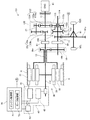
第一実施形態における駆動装置1は、図1に示すように、入力軸11と、第一駆動軸12と、第二駆動軸13と、出力軸14と、増速機構20と、二重ロータ型モータ30と、電力供給装置40と、ドグクラッチ機構50と、駆動軸ロック機構61と、パーキングロック機構65と、制御装置70とを備えて構成される。入力軸11は、ハウジングHに回転可能に支持され、エンジン81が出力する駆動力を駆動装置1に入力する。
<First embodiment>
(1. Overall configuration of the driving device 1)
As shown in FIG. 1, the drive device 1 in the first embodiment includes an input shaft 11, a first drive shaft 12, a second drive shaft 13, an output shaft 14, a speed increasing mechanism 20, and a double rotor. The mold motor 30, the power supply device 40, the dog clutch mechanism 50, the drive shaft lock mechanism 61, the parking lock mechanism 65, and the control device 70 are configured. The input shaft 11 is rotatably supported by the housing H and inputs a driving force output from the engine 81 to the driving device 1.
第一駆動軸12(本発明の「駆動軸」に相当する)は、ハウジングHに回転可能に支持され、入力軸11と平行に配置される。第二駆動軸13は、円筒状に形成され、第一駆動軸12と同軸上に配置される。第二駆動軸13は、第一駆動軸12に対して相対回転可能に支持される。第二駆動軸13は、後述する二重ロータ型モータ30に連結され、二重ロータ型モータ30のアウタロータ32と一体的に回転する。出力軸14は、ハイブリッド車両の駆動輪92L,92Rに、最終減速ギヤ17および差動機構91を介して連結される。最終減速ギヤ17は、差動機構91のデフリングギヤ91aに常時噛合している。
The first drive shaft 12 (corresponding to the “drive shaft” of the present invention) is rotatably supported by the housing H and is disposed in parallel with the input shaft 11. The second drive shaft 13 is formed in a cylindrical shape and is arranged coaxially with the first drive shaft 12. The second drive shaft 13 is supported so as to be rotatable relative to the first drive shaft 12. The second drive shaft 13 is connected to a double rotor type motor 30 described later, and rotates integrally with an outer rotor 32 of the double rotor type motor 30. Output shaft 14 is connected to drive wheels 92L, 92R of the hybrid vehicle via final reduction gear 17 and differential mechanism 91. The final reduction gear 17 is always meshed with the differential ring gear 91a of the differential mechanism 91.
上記の入力軸11および出力軸14には、エンジン出力用ギヤ対15が設けられている。本実施形態において、エンジン出力用ギヤ対15は、駆動ギヤ15a(本発明の「第一ギヤ」に相当する)および従動ギヤ15b(本発明の「第二ギヤ」に相当する)により構成される歯車機構である。エンジン出力用ギヤ対15の駆動ギヤ15aは、入力軸11に対して相対回転可能に設けられる。
The input shaft 11 and the output shaft 14 are provided with an engine output gear pair 15. In the present embodiment, the engine output gear pair 15 includes a drive gear 15a (corresponding to the “first gear” of the present invention) and a driven gear 15b (corresponding to the “second gear” of the present invention). It is a gear mechanism. The drive gear 15 a of the engine output gear pair 15 is provided so as to be rotatable relative to the input shaft 11.
エンジン出力用ギヤ対15の従動ギヤ15bは、出力軸14に固定され、且つ駆動ギヤ15aと噛合する。本実施形態において、従動ギヤ15bは、出力軸14において最終減速ギヤ17が配置された軸方向位置よりも二重ロータ型モータ30側に配置される。エンジン出力用ギヤ対15は、後述するドグクラッチ機構50により駆動ギヤ15aが入力軸11に選択的に連結されることによって、入力軸11と出力軸14との間で駆動力を伝達する。
The driven gear 15b of the engine output gear pair 15 is fixed to the output shaft 14 and meshes with the drive gear 15a. In the present embodiment, the driven gear 15b is disposed on the double rotor type motor 30 side with respect to the axial position where the final reduction gear 17 is disposed on the output shaft 14. The engine output gear pair 15 transmits driving force between the input shaft 11 and the output shaft 14 by selectively connecting the drive gear 15 a to the input shaft 11 by a dog clutch mechanism 50 described later.
また、第二駆動軸13および出力軸14には、モータ出力用ギヤ対16が設けられている。本実施形態において、モータ出力用ギヤ対16は、駆動ギヤ16aおよび従動ギヤ16bにより構成される歯車機構である。モータ出力用ギヤ対16の駆動ギヤ16aは、第二駆動軸13に固定される。
The second drive shaft 13 and the output shaft 14 are provided with a motor output gear pair 16. In the present embodiment, the motor output gear pair 16 is a gear mechanism including a drive gear 16a and a driven gear 16b. The drive gear 16 a of the motor output gear pair 16 is fixed to the second drive shaft 13.
モータ出力用ギヤ対16の従動ギヤ16bは、出力軸14に固定され、且つ駆動ギヤ16aと噛合する。本実施形態において、従動ギヤ16bは、出力軸14においてエンジン出力用ギヤ対15の従動ギヤ15bが配置された軸方向位置よりも二重ロータ型モータ30側に配置される。モータ出力用ギヤ対16は、第二駆動軸13と出力軸14との間で駆動力を伝達する。
The driven gear 16b of the motor output gear pair 16 is fixed to the output shaft 14 and meshes with the drive gear 16a. In the present embodiment, the driven gear 16b is disposed on the double rotor type motor 30 side of the output shaft 14 from the axial position where the driven gear 15b of the engine output gear pair 15 is disposed. The motor output gear pair 16 transmits a driving force between the second drive shaft 13 and the output shaft 14.
(1−1.増速機構20)
増速機構20は、入力軸11から入力される駆動力を増速する機構である。また、増速機構20は、入力軸11と同方向に第一駆動軸12が回転するように当該増速された駆動力を駆動軸に出力する。つまり、第一駆動軸12は、第一駆動軸12の軸方向(図1の左右方向)から駆動装置1を見た場合に、入力軸11が時計回りに回転すると、入力軸11とは異なる回転数で時計回りに回転する。また、第一駆動軸12から入力軸11に駆動力が伝達される場合には、増速機構20により駆動力が減速されて伝達される。
(1-1. Speed increasing mechanism 20)
The speed increasing mechanism 20 is a mechanism for increasing the driving force input from the input shaft 11. Further, the speed increasing mechanism 20 outputs the increased driving force to the drive shaft so that the first drive shaft 12 rotates in the same direction as the input shaft 11. That is, the first drive shaft 12 is different from the input shaft 11 when the input shaft 11 rotates clockwise when the drive device 1 is viewed from the axial direction of the first drive shaft 12 (left-right direction in FIG. 1). Rotates clockwise at the number of revolutions. Further, when the driving force is transmitted from the first driving shaft 12 to the input shaft 11, the driving force is decelerated by the speed increasing mechanism 20 and transmitted.
本実施形態において、増速機構20は、2組のギヤ対により入力軸11と同方向の回転を第一駆動軸12に出力する二段増速機構としている。具体的には、増速機構20は、副軸21と、第一ギヤ対22(本発明の「第一伝達機構」に相当する)と、第二ギヤ対23(本発明の「第二伝達機構」に相当する)とを有する。副軸21は、ハウジングHに回転可能に支持され、入力軸11と平行に配置される。
In the present embodiment, the speed increasing mechanism 20 is a two-stage speed increasing mechanism that outputs rotation in the same direction as the input shaft 11 to the first drive shaft 12 by two pairs of gears. Specifically, the speed increasing mechanism 20 includes a countershaft 21, a first gear pair 22 (corresponding to the “first transmission mechanism” of the present invention), and a second gear pair 23 (“second transmission of the present invention”). Corresponding to “mechanism”). The auxiliary shaft 21 is rotatably supported by the housing H and is disposed in parallel with the input shaft 11.
本実施形態において、第一ギヤ対22は、駆動ギヤ22aおよび従動ギヤ22bにより構成される歯車機構である。第一ギヤ対22の駆動ギヤ22aは、入力軸11に固定される。第一ギヤ対22の従動ギヤ22bは、副軸21に固定され、且つ駆動ギヤ22aと噛合する。このような構成により、副軸21は、入力軸11の回転方向とは逆方向に回転する。
In the present embodiment, the first gear pair 22 is a gear mechanism including a drive gear 22a and a driven gear 22b. The drive gear 22 a of the first gear pair 22 is fixed to the input shaft 11. The driven gear 22b of the first gear pair 22 is fixed to the auxiliary shaft 21 and meshes with the drive gear 22a. With such a configuration, the sub shaft 21 rotates in the direction opposite to the rotation direction of the input shaft 11.
本実施形態において、第二ギヤ対23は、駆動ギヤ23aおよび従動ギヤ23bにより構成される歯車機構である。第二ギヤ対23の駆動ギヤ23aは、副軸21において第一ギヤ対22の従動ギヤ22bが配置された軸方向位置よりもエンジン側(図1の右側)に配置され、副軸21に固定される。第二ギヤ対23の従動ギヤ23bは、第一駆動軸12に固定され、且つ駆動ギヤ23aと噛合する。
In the present embodiment, the second gear pair 23 is a gear mechanism including a drive gear 23a and a driven gear 23b. The drive gear 23 a of the second gear pair 23 is arranged on the engine side (right side in FIG. 1) with respect to the axial position where the driven gear 22 b of the first gear pair 22 is arranged on the sub shaft 21, and is fixed to the sub shaft 21. Is done. The driven gear 23b of the second gear pair 23 is fixed to the first drive shaft 12 and meshes with the drive gear 23a.
このような構成により、第一駆動軸12は、副軸21の回転方向とは逆方向に回転する。よって、増速機構20は、入力軸11と第一駆動軸12が同方向に回転するように、両軸間の駆動力の伝達を可能とする。また、増速機構20は、要求される増速比を全体として満たせばよい。つまり、第一ギヤ対22および第二ギヤ対23により併せて所定の増速比を満たしてもよいし、一方のギヤ対が等速で駆動力を伝達し且つ他方のギヤ対が所定の増速比で駆動力を伝達することにより当該所定の増速比を満たしてもよい。
With such a configuration, the first drive shaft 12 rotates in the direction opposite to the rotation direction of the sub shaft 21. Therefore, the speed increasing mechanism 20 enables transmission of driving force between both shafts so that the input shaft 11 and the first driving shaft 12 rotate in the same direction. Further, the speed increasing mechanism 20 may satisfy the required speed increasing ratio as a whole. That is, the first gear pair 22 and the second gear pair 23 may be combined to satisfy a predetermined speed increase ratio, one gear pair transmits a driving force at a constant speed, and the other gear pair has a predetermined speed increase. The predetermined speed increasing ratio may be satisfied by transmitting the driving force at the speed ratio.
(1−2.二重ロータ型モータ30)
二重ロータ型モータ30は、ステータ31(本発明の「固定子」に相当する)と、アウタロータ32(本発明の「第一回転子」に相当する)と、インナロータ33(本発明の「第二回転子」に相当する)とを有する。ステータ31は、全体形状としては円筒状に形成され、ハウジングHに固定される。ステータ31は、例えば電磁鋼板が積層されて形成されたコア部と、当該コア部の周方向に沿って導体が巻回されて形成された巻線部とにより構成される。ステータ31の巻線部は、交流電力が供給されると磁界を形成する。
(1-2. Double rotor type motor 30)
The double rotor type motor 30 includes a stator 31 (corresponding to the “stator” of the present invention), an outer rotor 32 (corresponding to the “first rotor” of the present invention), and an inner rotor 33 (“first rotor” of the present invention). Corresponding to “two rotors”. The stator 31 is formed in a cylindrical shape as a whole and is fixed to the housing H. The stator 31 includes, for example, a core portion formed by stacking electromagnetic steel plates and a winding portion formed by winding a conductor along the circumferential direction of the core portion. The winding portion of the stator 31 forms a magnetic field when AC power is supplied.
アウタロータ32は、ステータ31との間に径方向に所定の間隔を空けて配置される。また、アウタロータ32は、上述したように第二駆動軸13に一体的に連結される。これにより、アウタロータ32は、第二駆動軸13およびモータ出力用ギヤ対16を介して、出力軸14との間で駆動力を伝達可能に出力軸14に連結される。アウタロータ32は、全体形状としては円筒状に形成され、ハウジングHに対して相対回転可能に支持される。アウタロータ32は、例えば電磁鋼板が積層されて形成されたコア部と、当該コア部にN極とS極が周方向に交互に配置された永久磁石部とにより構成される。
The outer rotor 32 is arranged with a predetermined gap in the radial direction between the outer rotor 32 and the stator 31. Further, the outer rotor 32 is integrally connected to the second drive shaft 13 as described above. Thereby, the outer rotor 32 is connected to the output shaft 14 through the second drive shaft 13 and the motor output gear pair 16 so as to be able to transmit a driving force to and from the output shaft 14. The outer rotor 32 is formed in a cylindrical shape as a whole and is supported so as to be rotatable relative to the housing H. The outer rotor 32 includes a core part formed by stacking electromagnetic steel plates, for example, and a permanent magnet part in which N and S poles are alternately arranged in the circumferential direction on the core part.
インナロータ33は、アウタロータ32との間に径方向に所定の間隔を空けて配置される。また、インナロータ33は、第一駆動軸12と一体的に回転するように当該第一駆動軸12に連結される。インナロータ33は、全体形状としては円筒状に形成され、ハウジングHに対して相対回転可能に支持される。インナロータ33は、例えば電磁鋼板が積層されて形成されたコア部と、当該コア部の周方向に沿って導体が巻回されて形成された巻線部とにより構成される。インナロータ33の巻線部は、相対回転する磁界と鎖交すると交流電力を出力する。
The inner rotor 33 is disposed with a predetermined gap in the radial direction between the inner rotor 33 and the outer rotor 32. The inner rotor 33 is connected to the first drive shaft 12 so as to rotate integrally with the first drive shaft 12. The inner rotor 33 is formed in a cylindrical shape as a whole and is supported so as to be rotatable relative to the housing H. For example, the inner rotor 33 includes a core portion formed by stacking electromagnetic steel plates and a winding portion formed by winding a conductor along the circumferential direction of the core portion. The winding portion of the inner rotor 33 outputs alternating current power when interlinked with a relatively rotating magnetic field.
また、インナロータ33が固定される第一駆動軸12には、第一駆動軸12の外周面を周回する環状のスリップリングが交流の各相に対応して複数配置される。複数のスリップリングは、インナロータ33の巻線部の各相端子に対応して電気的に接続される。また、ハウジングHには、各相のスリップリングに対応したブラシが複数配置される。ブラシは、第一駆動軸12と一体的に回転するスリップリングの外周面を摺動して、スリップリングとの間の導通状態を維持する。
The first drive shaft 12 to which the inner rotor 33 is fixed is provided with a plurality of annular slip rings that circulate around the outer peripheral surface of the first drive shaft 12 in correspondence with each AC phase. The plurality of slip rings are electrically connected corresponding to each phase terminal of the winding portion of the inner rotor 33. The housing H is provided with a plurality of brushes corresponding to the slip rings of the respective phases. The brush slides on the outer peripheral surface of the slip ring that rotates integrally with the first drive shaft 12 and maintains a conduction state with the slip ring.
このような構成からなる二重ロータ型モータ30において、ステータ31の巻線部に交流電流が供給されると、ステータ31の巻線部が磁界を形成する。そうすると、電磁相互作用によりステータ31とアウタロータ32の永久磁石部との間に駆動力が発生する。一方で、アウタロータ32が第二駆動軸13から駆動力を伝達されて回転駆動すると、ステータ31の巻線部には、電磁誘導作用により交流電圧が誘起されてステータ31から出力される。つまり、ステータ31およびアウタロータ32は、電動機および発電機として機能する。
In the double rotor type motor 30 having such a configuration, when an alternating current is supplied to the winding portion of the stator 31, the winding portion of the stator 31 forms a magnetic field. Then, a driving force is generated between the stator 31 and the permanent magnet portion of the outer rotor 32 due to electromagnetic interaction. On the other hand, when the outer rotor 32 is driven to rotate by being transmitted with the driving force from the second drive shaft 13, an alternating voltage is induced in the winding portion of the stator 31 by an electromagnetic induction action and output from the stator 31. That is, the stator 31 and the outer rotor 32 function as an electric motor and a generator.
また、二重ロータ型モータ30において、インナロータ33の巻線部に交流電流が供給されると、インナロータ33の巻線部が磁界を形成する。そうすると、電磁相互作用によりインナロータ33とアウタロータ32の永久磁石部との間に駆動力が発生する。二重ロータ型モータ30は、当該駆動力により、インナロータ33を固定子としてアウタロータ32に駆動力を伝達可能であり、またインナロータ33がアウタロータ32と一体的に回転するようにカップリングとして機能させることも可能である。
Further, in the double rotor type motor 30, when an alternating current is supplied to the winding portion of the inner rotor 33, the winding portion of the inner rotor 33 forms a magnetic field. Then, a driving force is generated between the inner rotor 33 and the permanent magnet portion of the outer rotor 32 due to electromagnetic interaction. The double rotor type motor 30 can transmit a driving force to the outer rotor 32 by using the inner rotor 33 as a stator by the driving force, and also function as a coupling so that the inner rotor 33 rotates integrally with the outer rotor 32. Is also possible.
一方で、インナロータ33が第一駆動軸12から駆動力を伝達された回転駆動して、アウタロータ32に対して相対回転すると、インナロータ33の巻線部には、電磁誘導作用により交流電圧が誘起される。これにより、第一駆動軸12に配置されたスリップリングを介してブラシ26に交流電力が出力される。このように、アウタロータ32およびインナロータ33は、駆動力を伝達する機構を構成するとともに、発電する機能を有する。
On the other hand, when the inner rotor 33 is rotationally driven with the driving force transmitted from the first drive shaft 12 and rotates relative to the outer rotor 32, an AC voltage is induced in the winding portion of the inner rotor 33 by electromagnetic induction. The As a result, AC power is output to the brush 26 via the slip ring disposed on the first drive shaft 12. Thus, the outer rotor 32 and the inner rotor 33 constitute a mechanism for transmitting a driving force and have a function of generating electric power.
ここで、例えばステータ31または第一駆動軸12より駆動力を受けてアウタロータ32が回転駆動されインナロータ33に対して相対回転すると、インナロータ33の巻線部に鎖交するアウタロータ32の永久磁石部の磁束が変化し、電磁相互作用により駆動力が発生する。そのため、インナロータ33は、アウタロータ32との間で発生する駆動力を受ける。これに対して、二重ロータ型モータ30は、インナロータ33の巻線部に上記の駆動力に応じた交流電力を供給することで、インナロータ33が受ける駆動力を相殺する駆動力を発生させる0トルク制御を行うことが可能である。
Here, for example, when the outer rotor 32 is rotationally driven in response to the driving force from the stator 31 or the first drive shaft 12 and rotates relative to the inner rotor 33, the permanent magnet portion of the outer rotor 32 that is linked to the winding portion of the inner rotor 33. The magnetic flux changes and a driving force is generated by electromagnetic interaction. Therefore, the inner rotor 33 receives a driving force generated between the inner rotor 33 and the outer rotor 32. On the other hand, the double rotor type motor 30 generates a driving force that cancels the driving force received by the inner rotor 33 by supplying AC power corresponding to the driving force to the winding portion of the inner rotor 33. Torque control can be performed.
(1−3.電力供給装置40)
電力供給装置40は、二重ロータ型モータ30におけるステータ31およびインナロータ33に交流電力を供給する装置である。また、電力供給装置40は、二重ロータ型モータ30のステータ31およびインナロータ33において発電された交流電力を直流電力に変換して、バッテリー43に供給して蓄電する機能を有する。その他、電力供給装置40は、インナロータ33から出力された交流電流の一部をステータ31に供給可能に構成される。
(1-3. Power supply device 40)
The power supply device 40 is a device that supplies AC power to the stator 31 and the inner rotor 33 in the double rotor type motor 30. The power supply device 40 has a function of converting AC power generated in the stator 31 and the inner rotor 33 of the double rotor type motor 30 into DC power and supplying the DC power to the battery 43 to store it. In addition, the power supply device 40 is configured to be able to supply a part of the alternating current output from the inner rotor 33 to the stator 31.
この電力供給装置40は、第一インバータ41と、第二インバータ42と、バッテリー43とを有する。第一インバータ41および第二インバータ42は、直流電力を交流電力に変換する装置である。第一インバータ41は、ステータ31の巻線部、およびバッテリー43に電気的に接続される。第二インバータ42は、インナロータ33の巻線部、およびバッテリー43に電気的に接続される。
The power supply device 40 includes a first inverter 41, a second inverter 42, and a battery 43. The first inverter 41 and the second inverter 42 are devices that convert DC power into AC power. The first inverter 41 is electrically connected to the winding portion of the stator 31 and the battery 43. The second inverter 42 is electrically connected to the winding portion of the inner rotor 33 and the battery 43.
このような構成により、電力供給装置40は、バッテリー43が放電する直流電力を変換した交流電力を、またはインナロータ33の巻線部において発電された交流電力をステータ31に供給して、アウタロータ32を回転駆動させる。また、電力供給装置40は、車両の駆動輪92L,92Rから差動機構91、モータ出力用ギヤ対16、および第二駆動軸13を介してアウタロータ32に伝達された駆動力により交流電力を発電し、バッテリー43を充電する回生制御を行うことが可能である。
With such a configuration, the power supply device 40 supplies the stator 31 with AC power obtained by converting DC power discharged from the battery 43 or AC power generated at the winding portion of the inner rotor 33. Drive to rotate. The power supply device 40 generates AC power by the driving force transmitted from the driving wheels 92L and 92R of the vehicle to the outer rotor 32 via the differential mechanism 91, the motor output gear pair 16, and the second driving shaft 13. In addition, regenerative control for charging the battery 43 can be performed.
また、電力供給装置40は、バッテリー43が放電する直流電力を交流電力に変換し、インナロータ33に供給する。これにより、インナロータ33は、供給される電力量、およびアウタロータ32との差回転に応じて、アウタロータ32に駆動力を発生させたり、アウタロータ32と一体的に回転駆動したりするようになる。また、電力供給装置40は、エンジン81からエンジン出力用ギヤ対15、増速機構20、および第一駆動軸12を介して伝達された駆動力により交流電力を発電する制御を行うことが可能である。
Further, the power supply device 40 converts DC power discharged from the battery 43 into AC power and supplies the AC power to the inner rotor 33. As a result, the inner rotor 33 generates a driving force in the outer rotor 32 or is driven to rotate integrally with the outer rotor 32 in accordance with the amount of electric power supplied and the differential rotation with the outer rotor 32. Further, the power supply device 40 can perform control to generate AC power by the driving force transmitted from the engine 81 via the engine output gear pair 15, the speed increasing mechanism 20, and the first drive shaft 12. is there.
(1−4.ドグクラッチ機構50)
ドグクラッチ機構50は、入力軸11に対して相対回転可能に設けられたエンジン出力用ギヤ対15の駆動ギヤ15aを、入力軸11に対して選択的に連結する断接機構である。ドグクラッチ機構50が駆動ギヤ15aを入力軸11に対して連結した接続状態では、入力軸11および出力軸14は、エンジン出力用ギヤ対15により機械的に連結された状態となり、駆動ギヤ15aおよび従動ギヤ15bにより構成されるギヤ比に基づいて、相互に駆動力を伝達可能な状態となる。
(1-4. Dog clutch mechanism 50)
The dog clutch mechanism 50 is a connection / disconnection mechanism that selectively couples the drive gear 15 a of the engine output gear pair 15 provided to be rotatable relative to the input shaft 11 to the input shaft 11. In the connected state where the dog clutch mechanism 50 connects the drive gear 15a to the input shaft 11, the input shaft 11 and the output shaft 14 are mechanically connected by the engine output gear pair 15, and the drive gear 15a and the driven gear are connected. Based on the gear ratio formed by the gear 15b, the driving force can be transmitted to each other.
これに対して、ドグクラッチ機構50が駆動ギヤ15aを入力軸11に対して連結しない切断状態では、入力軸11および出力軸14は、機械的に連結されていない状態となり、互いに独立して回転可能となる。よって、ドグクラッチ機構50の切断状態では、入力軸11と出力軸14との間では、直接的に駆動力が伝達されない。
On the other hand, in a disconnected state where the dog clutch mechanism 50 does not connect the drive gear 15a to the input shaft 11, the input shaft 11 and the output shaft 14 are not mechanically connected and can rotate independently of each other. It becomes. Therefore, when the dog clutch mechanism 50 is in the disconnected state, the driving force is not directly transmitted between the input shaft 11 and the output shaft 14.
本実施形態において、ドグクラッチ機構50は、連結対象の部材間の差回転を同期させるシンクロ機構を有しないタイプの断接機構である。このドグクラッチ機構50は、クラッチハブ51と、スリーブ52と、クラッチリング53とを有する。クラッチハブ51は、入力軸11においてエンジン出力用ギヤ対15の駆動ギヤ15aに対して、二重ロータ型モータ30側の軸方向位置に配置される。クラッチハブ51は、駆動ギヤ15aが設けられた支持軸である入力軸11に固定され、入力軸11と一体的に回転する。クラッチハブ51の外周面には、入力軸11の軸方向に延在する外歯スプラインが形成されている。
In the present embodiment, the dog clutch mechanism 50 is a connecting / disconnecting mechanism that does not have a synchro mechanism that synchronizes differential rotation between members to be connected. The dog clutch mechanism 50 includes a clutch hub 51, a sleeve 52, and a clutch ring 53. The clutch hub 51 is disposed at an axial position on the double rotor type motor 30 side with respect to the drive gear 15 a of the engine output gear pair 15 on the input shaft 11. The clutch hub 51 is fixed to the input shaft 11 that is a support shaft provided with the drive gear 15 a and rotates integrally with the input shaft 11. An external spline that extends in the axial direction of the input shaft 11 is formed on the outer peripheral surface of the clutch hub 51.
スリーブ52の内周面には、クラッチハブ51の外歯スプラインと摺動可能に係合する内歯スプラインが形成されている。これにより、スリーブ52は、クラッチハブ51に対して相対回転不能に且つ入力軸11(駆動ギヤ15aが設けられた支持軸)の軸方向に相対移動可能にクラッチハブ51に嵌合される。クラッチリング53は、本実施形態において、エンジン出力用ギヤ対15の駆動ギヤ15aに一体的に固定される。クラッチリング53は、スリーブ52の軸方向位置に応じてスリーブ52と係脱可能に噛合する。
On the inner peripheral surface of the sleeve 52, an internal spline that is slidably engaged with an external spline of the clutch hub 51 is formed. Thus, the sleeve 52 is fitted to the clutch hub 51 so as not to rotate relative to the clutch hub 51 and to be relatively movable in the axial direction of the input shaft 11 (support shaft provided with the drive gear 15a). In this embodiment, the clutch ring 53 is integrally fixed to the drive gear 15a of the engine output gear pair 15. The clutch ring 53 meshes with the sleeve 52 in a detachable manner according to the axial position of the sleeve 52.
より詳細には、クラッチリング53のクラッチハブ51側の端面には、スリーブ52の内歯スプラインと係合可能なドグクラッチ部が形成される。これにより、スリーブ52の内歯スプラインとクラッチリング53のドグクラッチ部とが係合可能な軸方向位置にスリーブ52が移動されると、クラッチリング53は、スリーブ52およびクラッチハブ51を介して入力軸11に連結された状態となる。これにより、クラッチリング53が固定された駆動ギヤ15aは、ドグクラッチ機構50の接続状態において、入力軸11と一体的に回転する。
More specifically, a dog clutch portion that can be engaged with the internal spline of the sleeve 52 is formed on the end surface of the clutch ring 53 on the clutch hub 51 side. Thus, when the sleeve 52 is moved to an axial position where the internal spline of the sleeve 52 and the dog clutch portion of the clutch ring 53 can be engaged, the clutch ring 53 is connected to the input shaft via the sleeve 52 and the clutch hub 51. 11 is connected. As a result, the drive gear 15 a to which the clutch ring 53 is fixed rotates integrally with the input shaft 11 in the connected state of the dog clutch mechanism 50.
一方で、スリーブ52の内歯スプラインとクラッチリング53のドグクラッチ部とが離間した軸方向位置にスリーブ52が移動されると、クラッチリング53は、入力軸11に対して相対回転可能な状態となる。これにより、クラッチリング53が固定された駆動ギヤ15aは、ドグクラッチ機構50の切断状態において、入力軸11に対して相対回転可能な状態となる。このように、ドグクラッチ機構50は、スリーブ52の軸方向の移動制御によってエンジン出力用ギヤ対15を介して、入力軸11と出力軸14との間で駆動力を伝達可能とする。
On the other hand, when the sleeve 52 is moved to an axial position where the internal spline of the sleeve 52 and the dog clutch portion of the clutch ring 53 are separated from each other, the clutch ring 53 becomes rotatable relative to the input shaft 11. . As a result, the drive gear 15 a to which the clutch ring 53 is fixed becomes rotatable relative to the input shaft 11 when the dog clutch mechanism 50 is disconnected. As described above, the dog clutch mechanism 50 can transmit a driving force between the input shaft 11 and the output shaft 14 via the engine output gear pair 15 by the axial movement control of the sleeve 52.
(1−5.駆動軸ロック機構61)
駆動軸ロック機構61は、第一駆動軸12の回転を規制する機構である。これにより、駆動軸ロック機構61は、第一駆動軸12に連結された二重ロータ型モータ30におけるインナロータ33の回転を規制して、インナロータ33の停止状態を保持する。より詳細には、駆動軸ロック機構61は、例えば複数のブレーキディスクと、当該ブレーキディスクを押圧する押圧部材とを有する。
(1-5. Drive shaft locking mechanism 61)
The drive shaft lock mechanism 61 is a mechanism that restricts the rotation of the first drive shaft 12. Accordingly, the drive shaft locking mechanism 61 restricts the rotation of the inner rotor 33 in the double rotor type motor 30 connected to the first drive shaft 12 and maintains the stopped state of the inner rotor 33. More specifically, the drive shaft locking mechanism 61 includes, for example, a plurality of brake disks and a pressing member that presses the brake disks.
複数のブレーキディスクは、第一駆動軸12に相対回転不能に支持されるものと、ハウジングH側に相対回転不能に支持されるものとが、第一駆動軸12の軸方向に交互に配置される。押圧部材がブレーキディスクを押圧すると、ブレーキディスク同士が接触して第一駆動軸12の回転が規制される。また、押圧部材がブレーキディスクの押圧を解除すると、ブレーキディスク同士が離間して第一駆動軸12の回転が許容される。
The plurality of brake discs are alternately supported in the axial direction of the first drive shaft 12 and are supported on the first drive shaft 12 so as not to rotate relative to the first drive shaft 12. The When the pressing member presses the brake disc, the brake discs come into contact with each other, and the rotation of the first drive shaft 12 is restricted. Further, when the pressing member releases the pressure of the brake disc, the brake discs are separated from each other and the first drive shaft 12 is allowed to rotate.
また、駆動軸ロック機構61は、入力軸11の軸方向において増速機構20が配置された軸方向範囲Rsに配置される。具体的には、増速機構20における第一ギヤ対22の駆動ギヤ22aおよび従動ギヤ22bが配置された軸方向位置において、駆動軸ロック機構61のブレーキディスクが第一駆動軸12およびハウジングH側に固定される。
Further, the drive shaft locking mechanism 61 is disposed in the axial range Rs where the speed increasing mechanism 20 is disposed in the axial direction of the input shaft 11. Specifically, in the speed increasing mechanism 20, the brake disk of the drive shaft lock mechanism 61 is located on the first drive shaft 12 and the housing H side at the axial position where the drive gear 22a and the driven gear 22b of the first gear pair 22 are disposed. Fixed to.
(1−6.パーキングロック機構65)
パーキングロック機構65は、車両が停止した際に出力軸14の回転を規制する機構である。これにより、パーキングロック機構65は、出力軸14に差動機構91を介して連結された車両の駆動輪92L,92Rの回転を規制して、車両の停止状態を保持する。より詳細には、パーキングロック機構65は、例えば出力軸14に固定されたパーキングギヤと、ハウジングHに対して回転可能に支持されたパーキングポールとを有する。
(1-6. Parking lock mechanism 65)
The parking lock mechanism 65 is a mechanism that restricts the rotation of the output shaft 14 when the vehicle stops. As a result, the parking lock mechanism 65 regulates the rotation of the drive wheels 92L and 92R of the vehicle connected to the output shaft 14 via the differential mechanism 91, and holds the vehicle in a stopped state. More specifically, the parking lock mechanism 65 includes, for example, a parking gear fixed to the output shaft 14 and a parking pole that is rotatably supported with respect to the housing H.
パーキングギヤの外周面には、複数の外歯が形成される。パーキングポールは、パーキングギヤの外歯に係止可能な爪部が形成される。パーキングポールが回転軸周りに回転すると、パーキングポールの爪部がパーキングギヤの外歯に係止する。これにより、パーキングギヤは、回転を規制される。また、パーキングポールの爪部がパーキングギヤから離脱すると、パーキングギヤは、回転を許容される。
A plurality of external teeth are formed on the outer peripheral surface of the parking gear. The parking pole is formed with a claw portion that can be locked to the external teeth of the parking gear. When the parking pole rotates around the rotation axis, the pawl portion of the parking pole is locked to the external teeth of the parking gear. As a result, the parking gear is restricted from rotating. When the pawl portion of the parking pole is detached from the parking gear, the parking gear is allowed to rotate.
また、パーキングロック機構65は、入力軸11の軸方向において増速機構20が配置された軸方向範囲Rsに配置される。具体的には、増速機構20における第二ギヤ対23の駆動ギヤ23aおよび従動ギヤ23bが配置された軸方向位置において、パーキングロック機構65のパーキングギヤが出力軸14に固定される。
The parking lock mechanism 65 is disposed in the axial range Rs in which the speed increasing mechanism 20 is disposed in the axial direction of the input shaft 11. Specifically, the parking gear of the parking lock mechanism 65 is fixed to the output shaft 14 at the axial position where the drive gear 23 a and the driven gear 23 b of the second gear pair 23 are arranged in the speed increasing mechanism 20.
(1−7.制御装置70)
制御装置70は、ECUや各種メモリにより構成され、種々の車両情報に基づいて駆動装置1の動作を制御する。この制御装置70は、エンジン制御部71およびモータ制御部72を有する。エンジン制御部71は、例えばエンジン81のトルク特性を含む動作特性や現在のエンジン81の回転数などに基づいて、エンジン81の動作を制御する。
(1-7. Control device 70)
The control device 70 is configured by an ECU and various memories, and controls the operation of the drive device 1 based on various vehicle information. The control device 70 includes an engine control unit 71 and a motor control unit 72. The engine control unit 71 controls the operation of the engine 81 based on, for example, operation characteristics including torque characteristics of the engine 81, the current rotational speed of the engine 81, and the like.
モータ制御部72は、二重ロータ型モータ30および電力供給装置40の動作を制御する。モータ制御部72は、運転操作や車両状態に基づいて、第一インバータ41および第二インバータ42による交流電力の供給量などを調整する。また、制御装置70は、エンジン81および二重ロータ型モータ30の制御に加えて、ドグクラッチ機構50、駆動軸ロック機構61、およびパーキングロック機構65の動作を車両の走行状態に応じて制御する。
The motor control unit 72 controls operations of the double rotor type motor 30 and the power supply device 40. The motor control unit 72 adjusts the supply amount of AC power by the first inverter 41 and the second inverter 42 based on the driving operation and the vehicle state. In addition to the control of the engine 81 and the double rotor type motor 30, the control device 70 controls the operation of the dog clutch mechanism 50, the drive shaft lock mechanism 61, and the parking lock mechanism 65 according to the traveling state of the vehicle.
(2.駆動装置の動作)
車両状態に応じて制御される駆動装置1の動作について図2を参照して説明する。車両の走行状態には、主として、EV(Electric Vehicle)走行、HV(Hybrid Vehicle)走行、ENG(engine)走行が含まれる。図2では、上記の車両の走行状態に加えて、車両の停止状態を併せて表記している。
(2. Operation of drive unit)
The operation of the driving device 1 controlled according to the vehicle state will be described with reference to FIG. The traveling state of the vehicle mainly includes EV (Electric Vehicle) traveling, HV (Hybrid Vehicle) traveling, and ENG (engine) traveling. In FIG. 2, in addition to the traveling state of the vehicle described above, the stopped state of the vehicle is also shown.
(2−1.EV走行)
EV走行は、二重ロータ型モータ30が出力する駆動力のみを出力軸14を介して差動機構91に伝達する。このEV走行には、シングルモータ式とツインモータ式が含まれる。シングルモータ式は、ステータ31のみがアウタロータ32に駆動力を発生させる方式である。ツインモータ式は、ステータ31に加えてインナロータ33がアウタロータ32に駆動力を発生させる方式である。
(2-1. EV travel)
In EV traveling, only the driving force output from the double rotor type motor 30 is transmitted to the differential mechanism 91 via the output shaft 14. This EV traveling includes a single motor type and a twin motor type. The single motor system is a system in which only the stator 31 generates a driving force on the outer rotor 32. The twin motor system is a system in which the inner rotor 33 generates a driving force on the outer rotor 32 in addition to the stator 31.
(2−1−1.シングルモータ式のEV走行)
シングルモータ式のEV走行では、モータ制御部72は、第一インバータ41によりステータ31に所定の交流電力を供給して、アウタロータ32に駆動力を発生させる。これにより、アウタロータ32、第二駆動軸13、およびモータ出力用ギヤ対16の駆動ギヤ16aが一体的に回転して、出力軸14を介して差動機構91に駆動力が伝達される。
(2-1-1. Single-motor EV travel)
In the single motor type EV traveling, the motor control unit 72 supplies predetermined AC power to the stator 31 by the first inverter 41 and causes the outer rotor 32 to generate a driving force. As a result, the outer rotor 32, the second drive shaft 13, and the drive gear 16 a of the motor output gear pair 16 rotate integrally, and the driving force is transmitted to the differential mechanism 91 via the output shaft 14.
また、シングルモータ式のEV走行において、インナロータ33を用いた発電を要しない場合には、エンジン81は休止状態にされる。このとき、モータ制御部72は、アウタロータ32に対する相対回転によりインナロータ33に駆動力が発生するので、当該駆動力を相殺するために第二インバータ42によりインナロータ33に所定の交流電力を供給する0トルク制御を行う。
In addition, in the single motor EV traveling, when power generation using the inner rotor 33 is not required, the engine 81 is brought into a resting state. At this time, the motor control unit 72 generates a driving force in the inner rotor 33 due to the relative rotation with respect to the outer rotor 32. Therefore, the 0 torque that supplies predetermined AC power to the inner rotor 33 by the second inverter 42 to cancel the driving force. Take control.
一方で、シングルモータ式のEV走行において、インナロータ33を用いた発電を要する場合には、エンジン制御部71によりエンジン81が所定の回転数で回転される。エンジン81から出力された駆動力は、増速機構20により増速されて第一駆動軸12に伝達される。これにより、第一駆動軸12に一体的に固定されたインナロータ33が回転する。そうすると、インナロータ33がアウタロータ32に対して相対回転して、インナロータ33の巻線部に交流電圧が誘起される。
On the other hand, in the single motor EV traveling, when power generation using the inner rotor 33 is required, the engine control unit 71 rotates the engine 81 at a predetermined rotational speed. The driving force output from the engine 81 is accelerated by the speed increasing mechanism 20 and transmitted to the first drive shaft 12. As a result, the inner rotor 33 that is integrally fixed to the first drive shaft 12 rotates. Then, the inner rotor 33 rotates relative to the outer rotor 32, and an alternating voltage is induced in the winding portion of the inner rotor 33.
インナロータ33で発電された交流電力は、モータ制御部72によって第二インバータ42を介してバッテリー43に充電される。また、インナロータ33で発電された交流電力は、第二インバータ42および第一インバータ41を介してステータ31に供給されるようにしてもよい。このようなシングルモータ式のEV走行においては、エンジン81は、発電効率の観点から回転数を適宜設定される。つまり、エンジン81の駆動力は、直接的に出力軸14に伝達されず、インナロータ33による発電に用いられる。
The AC power generated by the inner rotor 33 is charged to the battery 43 by the motor control unit 72 via the second inverter 42. The AC power generated by the inner rotor 33 may be supplied to the stator 31 via the second inverter 42 and the first inverter 41. In such single-motor EV traveling, the engine 81 is appropriately set at a rotational speed from the viewpoint of power generation efficiency. That is, the driving force of the engine 81 is not directly transmitted to the output shaft 14 but is used for power generation by the inner rotor 33.
(2−1−2.ツインモータ式のEV走行)
ツインモータ式のEV走行では、モータ制御部72は、第一インバータ41および第二インバータ42によりステータ31およびインナロータ33に所定の交流電力を供給して、アウタロータ32に駆動力を発生させる。つまり、二重ロータ型モータ30は、インナロータ33を固定子としてアウタロータ32に駆動力を発生させる。このとき、インナロータ33は、アウタロータ32から反作用としての駆動力を受ける。
(2-1-2. Twin motor EV travel)
In the twin motor type EV traveling, the motor control unit 72 supplies predetermined AC power to the stator 31 and the inner rotor 33 by the first inverter 41 and the second inverter 42 to generate a driving force in the outer rotor 32. That is, the double rotor type motor 30 generates a driving force in the outer rotor 32 using the inner rotor 33 as a stator. At this time, the inner rotor 33 receives a driving force as a reaction from the outer rotor 32.
そこで、本実施形態の駆動装置1において、制御装置70は、駆動軸ロック機構61を動作させて、第一駆動軸12の回転を規制する。これにより、インナロータ33がアウタロータ32より受ける駆動力を吸収する。よって、制御装置70は、インナロータ33をアウタロータ32に対する固定子として好適に作用させることが可能となる。
Therefore, in the drive device 1 of the present embodiment, the control device 70 operates the drive shaft lock mechanism 61 to restrict the rotation of the first drive shaft 12. As a result, the driving force received by the inner rotor 33 from the outer rotor 32 is absorbed. Therefore, the control device 70 can cause the inner rotor 33 to act suitably as a stator for the outer rotor 32.
(2−2.HV走行)
HV走行は、二重ロータ型モータ30が出力する駆動力、およびエンジン81が出力する駆動力を差動機構91に伝達する。このHV走行には、モータパス方式と直達パス方式が含まれる。モータパス方式は、エンジン81が出力する駆動力を、二重ロータ型モータ30を経由して差動機構91に伝達する方式である。直達パス方式は、エンジン81が出力する駆動力を、ドグクラッチ機構50の作動により二重ロータ型モータ30を経由することなく直接的に差動機構91に伝達する方式である。
(2-2. HV traveling)
In HV traveling, the driving force output by the double rotor type motor 30 and the driving force output by the engine 81 are transmitted to the differential mechanism 91. This HV traveling includes a motor path system and a direct path system. The motor path method is a method for transmitting the driving force output from the engine 81 to the differential mechanism 91 via the double rotor type motor 30. The direct path system is a system in which the driving force output from the engine 81 is directly transmitted to the differential mechanism 91 without passing through the double rotor motor 30 by the operation of the dog clutch mechanism 50.
(2−2−1.モータパス方式のHV走行)
モータパス方式のHV走行では、モータ制御部72は、第一インバータ41によりステータ31に所定の交流電力を供給して、アウタロータ32に駆動力を発生させる。さらに、モータ制御部72は、第二インバータ42によりインナロータ33に所定の交流電力を供給して、インナロータ33がアウタロータ32と一体的に回転するカップリング状態とする。
(2-2-1. HV traveling with motor path)
In the motor path type HV traveling, the motor control unit 72 supplies predetermined AC power to the stator 31 by the first inverter 41 and causes the outer rotor 32 to generate a driving force. Further, the motor control unit 72 supplies predetermined AC power to the inner rotor 33 by the second inverter 42, and sets the coupling state in which the inner rotor 33 rotates integrally with the outer rotor 32.
一方で、エンジン制御部71は、所定の回転数でエンジン81が回転するように制御する。エンジン81から出力された駆動力は、増速機構20により増速されて第一駆動軸12に伝達される。第一駆動軸12に伝達された駆動力は、カップリング状態にあるインナロータ33からアウタロータ32へと伝達され、二重ロータ型モータ30が出力する駆動力と合成される。アウタロータ32において合成された駆動力は、第二駆動軸13、モータ出力用ギヤ対16、および出力軸14を介して差動機構91に伝達される。
On the other hand, the engine control unit 71 controls the engine 81 to rotate at a predetermined rotation speed. The driving force output from the engine 81 is accelerated by the speed increasing mechanism 20 and transmitted to the first drive shaft 12. The driving force transmitted to the first drive shaft 12 is transmitted from the inner rotor 33 in the coupled state to the outer rotor 32 and is combined with the driving force output from the double rotor type motor 30. The driving force synthesized in the outer rotor 32 is transmitted to the differential mechanism 91 via the second driving shaft 13, the motor output gear pair 16, and the output shaft 14.
(2−2−2.直達パス方式のHV走行)
直達パス方式のHV走行では、制御装置70は、ドグクラッチ機構50を接続状態として、入力軸11と出力軸14が機械的に連結された状態とする。また、エンジン制御部71は、エンジン81が所定の回転数で回転するように制御する。エンジン81が出力する駆動力は、ドグクラッチ機構50および出力軸14を介して差動機構91に伝達される。
(2-2-2. HV driving with direct path method)
In the HV traveling of the direct path method, the control device 70 sets the dog clutch mechanism 50 in the connected state and sets the input shaft 11 and the output shaft 14 in a mechanically connected state. Further, the engine control unit 71 controls the engine 81 to rotate at a predetermined rotational speed. The driving force output from the engine 81 is transmitted to the differential mechanism 91 via the dog clutch mechanism 50 and the output shaft 14.
また、モータ制御部72は、第一インバータ41によりステータ31に所定の交流電力を供給して、アウタロータ32に駆動力を発生させる。二重ロータ型モータ30が出力する駆動力は、第二駆動軸13およびモータ出力用ギヤ対16を介して出力軸14に伝達される。これにより、エンジン81および二重ロータ型モータ30が出力するそれぞれの駆動力は、出力軸14で合成されて差動機構91に伝達される。
Further, the motor control unit 72 supplies predetermined AC power to the stator 31 by the first inverter 41 and causes the outer rotor 32 to generate a driving force. The driving force output by the double rotor type motor 30 is transmitted to the output shaft 14 via the second drive shaft 13 and the motor output gear pair 16. As a result, the driving forces output from the engine 81 and the double rotor type motor 30 are combined by the output shaft 14 and transmitted to the differential mechanism 91.
このような直達パス方式のHV走行において、二重ロータ型モータ30のインナロータ33は、エンジン81の駆動力を増速機構20および第一駆動軸12を介して伝達される。そのため、インナロータ33は、アウタロータ32に対して相対回転する。ここで、増速機構20は、入力軸11と同方向に第一駆動軸12が回転するように、増速させたエンジン81の駆動力を第一駆動軸12に出力する。
In such direct path type HV traveling, the inner rotor 33 of the double rotor type motor 30 transmits the driving force of the engine 81 via the speed increasing mechanism 20 and the first drive shaft 12. Therefore, the inner rotor 33 rotates relative to the outer rotor 32. Here, the speed increasing mechanism 20 outputs the increased driving force of the engine 81 to the first drive shaft 12 so that the first drive shaft 12 rotates in the same direction as the input shaft 11.
そのため、インナロータ33の回転方向がアウタロータ32と同方向となり、インナロータ33とアウタロータ32の差回転が比較的小さくなる。このように、本実施形態の駆動装置1においては、入力と出力が同方向となる増速機構20を採用することにより、アウタロータ32に対するインナロータ33の差回転の低減が図られている。
Therefore, the rotation direction of the inner rotor 33 is the same as that of the outer rotor 32, and the differential rotation between the inner rotor 33 and the outer rotor 32 becomes relatively small. Thus, in the drive device 1 of the present embodiment, the differential rotation of the inner rotor 33 with respect to the outer rotor 32 is reduced by employing the speed increasing mechanism 20 in which the input and the output are in the same direction.
なお、直達パス方式のHV走行において、インナロータ33とアウタロータ32の差回転が比較的小さくとも発生している。ここで、インナロータ33を用いた発電を要しない場合には、本実施形態においては、インナロータ33がアウタロータ32に対する相対回転により受ける駆動力を相殺する駆動力を発生させるように、モータ制御部72は、第二インバータ42によりインナロータ33に所定の交流電力を供給する0トルク制御を行う。
Note that, in the HV traveling of the direct path method, even if the differential rotation between the inner rotor 33 and the outer rotor 32 is relatively small, it occurs. Here, when power generation using the inner rotor 33 is not required, in the present embodiment, the motor control unit 72 is configured to generate a driving force that cancels the driving force received by the inner rotor 33 relative to the outer rotor 32. Then, zero torque control for supplying predetermined AC power to the inner rotor 33 by the second inverter 42 is performed.
一方で、直達パス方式のHV走行において、インナロータ33を用いた発電を要する場合には、インナロータ33およびアウタロータ32の差回転によって、インナロータ33の巻線部に交流電圧が誘起される。インナロータ33で発電された交流電力は、モータ制御部72によって第二インバータ42を介してバッテリー43に充電される。また、インナロータ33で発電された交流電力は、第二インバータ42および第一インバータ41を介してステータ31に供給されるようにしてもよい。
On the other hand, when power generation using the inner rotor 33 is required in the direct path type HV traveling, an AC voltage is induced in the winding portion of the inner rotor 33 due to the differential rotation of the inner rotor 33 and the outer rotor 32. The AC power generated by the inner rotor 33 is charged to the battery 43 by the motor control unit 72 via the second inverter 42. The AC power generated by the inner rotor 33 may be supplied to the stator 31 via the second inverter 42 and the first inverter 41.
(2−3.ENG走行)
ENG走行は、エンジン81が出力する駆動力のみを差動機構91に伝達する。このENG走行には、モータパス方式と直達パス方式が含まれる。ENG走行におけるモータパス方式および直達パス方式は、HV走行におけるモータパス方式および直達パス方式と実質的に同一である。
(2-3. ENG travel)
In ENG traveling, only the driving force output from the engine 81 is transmitted to the differential mechanism 91. This ENG traveling includes a motor path system and a direct path system. The motor path method and direct path method in ENG traveling are substantially the same as the motor path method and direct path method in HV traveling.
(2−3−1.モータパス方式のENG走行)
モータパス方式のENG走行では、モータ制御部72は、第二インバータ42によりインナロータ33に所定の交流電力を供給して、インナロータ33がアウタロータ32と一体的に回転するカップリング状態とする。エンジン制御部71は、所定の回転数でエンジン81が回転するように制御する。
(2-3-1. ENG traveling by motor path method)
In the motor path type ENG traveling, the motor control unit 72 supplies predetermined AC power to the inner rotor 33 by the second inverter 42, so that the inner rotor 33 rotates integrally with the outer rotor 32. The engine control unit 71 controls the engine 81 to rotate at a predetermined rotational speed.
エンジン81から出力された駆動力は、増速機構20により増速されて第一駆動軸12に伝達される。第一駆動軸12に伝達された駆動力は、カップリング状態にあるインナロータ33からアウタロータ32へと伝達される。アウタロータ32に伝達された駆動力は、第二駆動軸13、モータ出力用ギヤ対16、および出力軸14を介して差動機構91に伝達される。
The driving force output from the engine 81 is accelerated by the speed increasing mechanism 20 and transmitted to the first drive shaft 12. The driving force transmitted to the first drive shaft 12 is transmitted from the inner rotor 33 in the coupled state to the outer rotor 32. The driving force transmitted to the outer rotor 32 is transmitted to the differential mechanism 91 via the second driving shaft 13, the motor output gear pair 16, and the output shaft 14.
なお、モータパス方式のENG走行において、カップリング状態にあるインナロータ33およびアウタロータ32が回転すると、ステータ31に対して相対回転することになる。そのため、ステータ31は、アウタロータ32から反作用としての駆動力を受ける。そこで、本実施形態において、この駆動力を相殺する駆動力を発生させるように、モータ制御部72は、第一インバータ41によりステータ31に所定の交流電力を供給する0トルク制御を行う。
In the motor path type ENG traveling, when the inner rotor 33 and the outer rotor 32 in the coupled state rotate, they rotate relative to the stator 31. Therefore, the stator 31 receives a driving force as a reaction from the outer rotor 32. Therefore, in the present embodiment, the motor control unit 72 performs zero torque control for supplying predetermined AC power to the stator 31 by the first inverter 41 so as to generate a driving force that cancels the driving force.
(2−3−2.直達パス方式のENG走行)
直達パス方式のENG走行では、制御装置70は、ドグクラッチ機構50を接続状態として、入力軸11と出力軸14が機械的に連結された状態とする。また、エンジン制御部71は、所定の回転数でエンジン81が回転するように制御する。エンジン81が出力する駆動力は、ドグクラッチ機構50および出力軸14を介して差動機構91に伝達される。
(2-3-2. ENG traveling with direct pass method)
In the direct-pass-type ENG traveling, the control device 70 sets the dog clutch mechanism 50 in the connected state and sets the input shaft 11 and the output shaft 14 in a mechanically connected state. The engine control unit 71 controls the engine 81 to rotate at a predetermined rotation speed. The driving force output from the engine 81 is transmitted to the differential mechanism 91 via the dog clutch mechanism 50 and the output shaft 14.
なお、直達パス方式のENG走行において、アウタロータ32は、出力軸14の回転によりモータ出力用ギヤ対16を介して駆動力を伝達される第二駆動軸13とともに回転する。そのため、ステータ31は、アウタロータ32から反作用としての駆動力を受ける。そこで、本実施形態において、この駆動力を相殺する駆動力を発生させるように、モータ制御部72は、第一インバータ41によりステータ31に所定の交流電力を供給する0トルク制御を行う。
In the direct path type ENG traveling, the outer rotor 32 rotates together with the second drive shaft 13 to which the driving force is transmitted through the motor output gear pair 16 by the rotation of the output shaft 14. Therefore, the stator 31 receives a driving force as a reaction from the outer rotor 32. Therefore, in the present embodiment, the motor control unit 72 performs zero torque control for supplying predetermined AC power to the stator 31 by the first inverter 41 so as to generate a driving force that cancels the driving force.
また、インナロータ33は、増速機構20を介して駆動力を伝達される第一駆動軸12とともに回転する。そのため、直達パス方式のENG走行では、アウタロータ32とインナロータ33の差回転が発生する。但し、上記のように、増速機構20の採用によりアウタロータ32に対するインナロータ33の差回転の低減が図られており、直達パス方式のHV走行と同様に、上記の差回転による影響が抑制されている。
Further, the inner rotor 33 rotates together with the first drive shaft 12 to which the driving force is transmitted via the speed increasing mechanism 20. Therefore, in the direct-pass type ENG traveling, differential rotation between the outer rotor 32 and the inner rotor 33 occurs. However, as described above, by adopting the speed increasing mechanism 20, the differential rotation of the inner rotor 33 with respect to the outer rotor 32 is reduced, and the influence of the differential rotation is suppressed as in the HV traveling of the direct path method. Yes.
ここで、インナロータ33を用いた発電を要しない場合には、本実施形態においては、インナロータ33がアウタロータ32に対する相対回転により受ける駆動力を相殺する駆動力を発生させるように、モータ制御部72は、第二インバータ42によりインナロータ33に所定の交流電力を供給する0トルク制御を行う。
Here, when power generation using the inner rotor 33 is not required, in the present embodiment, the motor control unit 72 is configured to generate a driving force that cancels the driving force received by the inner rotor 33 relative to the outer rotor 32. Then, zero torque control for supplying predetermined AC power to the inner rotor 33 by the second inverter 42 is performed.
一方で、直達パス方式のENG走行において、インナロータ33を用いた発電を要する場合には、インナロータ33およびアウタロータ32の差回転によって、インナロータ33の巻線部に交流電圧が誘起される。インナロータ33で発電された交流電力は、モータ制御部72によって第二インバータ42を介してバッテリー43に充電される。また、インナロータ33で発電された交流電力は、第二インバータ42および第一インバータ41を介してステータ31に供給されるようにしてもよい。
On the other hand, in the direct-pass-type ENG traveling, when power generation using the inner rotor 33 is required, an AC voltage is induced in the winding portion of the inner rotor 33 due to the differential rotation of the inner rotor 33 and the outer rotor 32. The AC power generated by the inner rotor 33 is charged to the battery 43 by the motor control unit 72 via the second inverter 42. The AC power generated by the inner rotor 33 may be supplied to the stator 31 via the second inverter 42 and the first inverter 41.
(2−4.停止状態)
車両の停止状態は、出力軸14には駆動力が伝達されず、車速が0の状態である。制御装置70は、パーキングロック機構65を動作させて、出力軸14の回転を規制する。これにより、出力軸14に機械的に連結された駆動輪92L,92Rの回転が規制されて、車両の停止状態が保持される。
(2-4. Stop state)
The stop state of the vehicle is a state in which no driving force is transmitted to the output shaft 14 and the vehicle speed is zero. The control device 70 operates the parking lock mechanism 65 to restrict the rotation of the output shaft 14. Thereby, the rotation of the drive wheels 92L and 92R mechanically connected to the output shaft 14 is restricted, and the stopped state of the vehicle is maintained.
(3.同期制御)
上述した車両の走行状態において、車両がEV走行からエンジン81によるアシストを加える直達パス方式のHV走行に移行する場合には、ドグクラッチ機構50を切断状態から接続状態に移行させる必要がある。しかしながら、ドグクラッチ機構50は、シンクロ機構を有しないタイプの断接機構であるため、車両の走行中に接続状態への移行が容易でなく、移行できたとしても大きな衝撃力が加えられるおそれがある。
(3. Synchronous control)
In the traveling state of the vehicle described above, when the vehicle transitions from EV traveling to HV traveling of the direct path method in which assistance by the engine 81 is applied, it is necessary to shift the dog clutch mechanism 50 from the disconnected state to the connected state. However, since the dog clutch mechanism 50 is a type of connection / disconnection mechanism that does not have a synchro mechanism, it is not easy to shift to the connected state during traveling of the vehicle, and even if it can be shifted, a large impact force may be applied. .
そこで、駆動装置1は、入力軸11の回転数と、車速に応じて回転するエンジン出力用ギヤ対15の駆動ギヤ15aの回転数とを同期する制御を行う。これにより、入力軸11に固定されたクラッチハブ51と、駆動ギヤ15aに一体的に固定されたクラッチリング53との差回転が小さくなり、駆動装置1は、ドグクラッチ機構50を接続状態に移行可能となる。
Therefore, the drive device 1 performs control to synchronize the rotational speed of the input shaft 11 and the rotational speed of the drive gear 15a of the engine output gear pair 15 that rotates according to the vehicle speed. Thereby, the differential rotation between the clutch hub 51 fixed to the input shaft 11 and the clutch ring 53 fixed integrally to the drive gear 15a is reduced, and the drive device 1 can shift the dog clutch mechanism 50 to the connected state. It becomes.
また、上記の同期制御は、入力軸11が所定の回転数となるように入力軸11に駆動力を伝達することで行われる。本実施形態において、モータ制御部72は、ドグクラッチ機構50が接続状態にされる場合に、二重ロータ型モータ30のインナロータ33の回転数を制御することによって、増速機構20を介して入力軸11(駆動ギヤ15aが設けられた支持軸)に駆動力を伝達する。これにより、モータ制御部72は、入力軸11の回転数とエンジン出力用ギヤ対15の駆動ギヤ15aの回転数とを同期させる。
In addition, the synchronous control is performed by transmitting a driving force to the input shaft 11 so that the input shaft 11 has a predetermined rotational speed. In the present embodiment, the motor control unit 72 controls the input shaft via the speed increasing mechanism 20 by controlling the rotation speed of the inner rotor 33 of the double rotor type motor 30 when the dog clutch mechanism 50 is in the connected state. The driving force is transmitted to 11 (support shaft provided with the driving gear 15a). As a result, the motor control unit 72 synchronizes the rotational speed of the input shaft 11 with the rotational speed of the drive gear 15a of the engine output gear pair 15.
このような同期制御によると、エンジン81により入力軸11に駆動力を伝達して行う同期制御と比較すると、エンジン制御よりもモータ制御の方が所定の回転数に正確に且つ迅速に制御可能であることから、ドグクラッチ機構50の接続状態への移行に要する時間の短縮を図ることができる。また、同期制御を高精度にできることから、ドグクラッチ機構50を接続状態に移行した際の衝撃力が低減される。
According to such synchronous control, compared with synchronous control performed by transmitting driving force to the input shaft 11 by the engine 81, motor control can be controlled more accurately and quickly at a predetermined rotational speed than engine control. Therefore, it is possible to shorten the time required for the dog clutch mechanism 50 to shift to the connected state. In addition, since the synchronization control can be performed with high accuracy, the impact force when the dog clutch mechanism 50 is shifted to the connected state is reduced.
(4.回生制御)
上述した車両の走行状態において、二重ロータ型モータ30のアウタロータ32は、車速に応じた回転数で回転する。そのため、何れの走行状態(EV走行、HV走行、ENG走行)において、駆動装置1は、運転操作に応じて、アウタロータ32による駆動力の出力または0トルク制御に替えて、アウタロータ32に伝達された駆動力により交流電力を発電する回生制御を行うことが可能である。
(4. Regenerative control)
In the traveling state of the vehicle described above, the outer rotor 32 of the double rotor type motor 30 rotates at a rotational speed corresponding to the vehicle speed. Therefore, in any traveling state (EV traveling, HV traveling, ENG traveling), the driving device 1 is transmitted to the outer rotor 32 instead of driving force output or 0 torque control by the outer rotor 32 according to the driving operation. It is possible to perform regenerative control in which AC power is generated by driving force.
(5.第一実施形態の構成による効果)
上述した駆動装置1は、駆動用モータおよび発電用モータとして、二重ロータ型モータ30を備える。そのため、例えば、アウタロータ32は、要求されるモータ容量に応じて外径を適宜設定される。また、二重ロータ型モータ30は、アウタロータ32の内側にインナロータ33を収容する構成である。そのため、駆動装置1の軸方向の寸法を拡大することなく、独立して動作可能なアウタロータ32およびインナロータ33を配置できるので、装置全体としての小型化を図ることができる。
(5. Effects of the configuration of the first embodiment)
The drive device 1 described above includes a double rotor type motor 30 as a drive motor and a power generation motor. Therefore, for example, the outer rotor 32 has an outer diameter appropriately set according to a required motor capacity. The double rotor type motor 30 is configured to accommodate the inner rotor 33 inside the outer rotor 32. Therefore, the outer rotor 32 and the inner rotor 33 that can be operated independently can be arranged without increasing the axial dimension of the drive device 1, and thus the overall size of the device can be reduced.
ここで、車両が直達パス方式のHV走行およびENG走行の状態では、アウタロータ32とインナロータ33との間に差回転が発生する。これに対して、駆動装置1は、入力軸11と同方向に第一駆動軸12が回転するように増速された駆動力を第一駆動軸12に出力する増速機構20を備える。これにより、インナロータ33は、増速機構20によって入力軸11の回転方向と同方向に回転する。
Here, differential rotation occurs between the outer rotor 32 and the inner rotor 33 when the vehicle is in the direct-pass type HV traveling and ENG traveling. In contrast, the drive device 1 includes a speed increasing mechanism 20 that outputs to the first drive shaft 12 a driving force increased so that the first drive shaft 12 rotates in the same direction as the input shaft 11. Thereby, the inner rotor 33 is rotated in the same direction as the rotation direction of the input shaft 11 by the speed increasing mechanism 20.
つまり、インナロータ33の回転方向は、出力軸14とは逆回転しているアウタロータ32の回転方向と同方向となる。従って、例えば一組のギヤ対により増速を行う一段増速機構を採用した場合と比較して、インナロータ33とアウタロータ32の差回転が小さくなる。これにより、駆動装置1において、二重ロータ型モータ30における動力損失の発生が抑制される。
That is, the rotation direction of the inner rotor 33 is the same as the rotation direction of the outer rotor 32 that rotates in the reverse direction to the output shaft 14. Therefore, for example, the differential rotation between the inner rotor 33 and the outer rotor 32 is reduced as compared with a case where a one-stage speed increasing mechanism that speeds up with a pair of gear pairs is employed. Thereby, in the drive device 1, generation of power loss in the double rotor type motor 30 is suppressed.
また、増速機構20は、2組のギヤ対(第一ギヤ対22および第二ギヤ対23)を有する二段増速機構を採用する。これにより、増速機構20は、入力軸11と同方向に第一駆動軸12が回転するように、増速された駆動力を第一駆動軸12に出力できる。また、二段階で要求される増速比を得る構成とすることができるので、増速機構20の設計自由度が向上する。
The speed increasing mechanism 20 employs a two-stage speed increasing mechanism having two pairs of gears (a first gear pair 22 and a second gear pair 23). Thus, the speed increasing mechanism 20 can output the increased driving force to the first drive shaft 12 so that the first drive shaft 12 rotates in the same direction as the input shaft 11. Moreover, since it can be set as the structure which obtains the speed increase ratio requested | required in two steps, the design freedom of the speed increase mechanism 20 improves.
また、駆動装置1は、駆動ギヤ15aを入力軸11に対して選択的に連結して、入力軸11と出力軸14との間で駆動力を伝達可能とするドグクラッチ機構50を備える。これにより、駆動装置1は、ドグクラッチ機構50の作動によりエンジン81が出力する駆動力を、増速機構20、第一駆動軸12、および二重ロータ型モータ30を介さずに、差動機構91に伝達することが可能となる。これにより、動力損失を低減し、エンジン81が出力する駆動力を効率的に伝達できる。
In addition, the drive device 1 includes a dog clutch mechanism 50 that selectively couples the drive gear 15 a to the input shaft 11 so that the drive force can be transmitted between the input shaft 11 and the output shaft 14. As a result, the driving device 1 causes the differential mechanism 91 to output the driving force output from the engine 81 by the operation of the dog clutch mechanism 50 without passing through the speed increasing mechanism 20, the first drive shaft 12, and the double rotor type motor 30. Can be communicated to. Thereby, power loss can be reduced and the driving force output from the engine 81 can be efficiently transmitted.
また、駆動装置1は、断接機構としてシンクロ機構を有しないタイプのドグクラッチ機構50を採用する。さらに、駆動装置1は、ドグクラッチ機構50が接続状態にされる場合に、インナロータ33の回転数を制御することによって、入力軸11に駆動力を伝達して、入力軸11(駆動ギヤ15aが設けられた支持軸)の回転数と駆動ギヤ15aの回転数とを同期させる制御を行うモータ制御部72をさらに備える。
The drive device 1 employs a dog clutch mechanism 50 of a type that does not have a synchro mechanism as a connection / disconnection mechanism. Further, when the dog clutch mechanism 50 is brought into the connected state, the driving device 1 transmits the driving force to the input shaft 11 by controlling the rotational speed of the inner rotor 33, so that the input shaft 11 (the driving gear 15 a is provided). A motor control unit 72 that performs control to synchronize the rotation speed of the support shaft) and the rotation speed of the drive gear 15a.
ドグクラッチ機構50は、他種の断接機構と比較すると部品点数が少なく、引き摺りトルクなどが発生しない点で有利である。しかし、ドグクラッチ機構50は、シンクロ機構を有しないタイプであることから、接続状態への移行の際の衝撃を低減するためには、ある程度の同期制御を要する。そこで、本実施形態の駆動装置1は、モータ制御部72がインナロータ33を所定の回転数で回転させて、増速機構20を介して入力軸11の回転数を制御する。これにより、入力軸11の回転数と、エンジン出力用ギヤ対15の駆動ギヤ15aの回転数とが同期される。このように、モータ駆動力により同期制御することにより、エンジン駆動力により同期制御する場合と比較して、同期制御の精度を向上できる。よって、ドグクラッチ機構50を採用した駆動装置1において、接続時の衝撃力の発生を抑制できる。
The dog clutch mechanism 50 is advantageous in that the number of parts is small compared to other types of connection / disconnection mechanisms and drag torque is not generated. However, since the dog clutch mechanism 50 is a type that does not have a synchronization mechanism, a certain degree of synchronization control is required to reduce the impact at the time of transition to the connected state. Therefore, in the driving apparatus 1 of the present embodiment, the motor control unit 72 rotates the inner rotor 33 at a predetermined rotation speed, and controls the rotation speed of the input shaft 11 via the speed increasing mechanism 20. Thereby, the rotation speed of the input shaft 11 and the rotation speed of the drive gear 15a of the engine output gear pair 15 are synchronized. Thus, by performing synchronous control with the motor driving force, the accuracy of the synchronous control can be improved as compared with the case of performing synchronous control with the engine driving force. Therefore, in the drive device 1 that employs the dog clutch mechanism 50, it is possible to suppress the generation of impact force at the time of connection.
また、駆動軸ロック機構61は、入力軸11の軸方向において増速機構20が配置された軸方向範囲Rsに配置される。
インナロータ33は、例えば車両がツインモータ式のEV走行の状態では、アウタロータ32に対しては固定子として作用する。これに対して、駆動装置1は、ツインモータ式のEV走行においては、駆動軸ロック機構61により第一駆動軸12を介してインナロータ33の回転を規制する。これにより、インナロータ33をアウタロータ32に対する固定子として好適に作用させることができる。また、増速機構20が配置された軸方向範囲Rsに駆動軸ロック機構61が配置されるので、装置内のスペースを有効利用して装置全体としての小型化を図ることができる。
Further, the drive shaft locking mechanism 61 is disposed in the axial range Rs where the speed increasing mechanism 20 is disposed in the axial direction of the input shaft 11.
The inner rotor 33 acts as a stator with respect to the outer rotor 32, for example, when the vehicle is in a twin motor EV traveling state. On the other hand, the drive device 1 regulates the rotation of the inner rotor 33 via the first drive shaft 12 by the drive shaft lock mechanism 61 in the twin motor type EV traveling. Thereby, the inner rotor 33 can be suitably acted as a stator for the outer rotor 32. Further, since the drive shaft locking mechanism 61 is disposed in the axial range Rs where the speed increasing mechanism 20 is disposed, it is possible to reduce the size of the entire apparatus by effectively using the space in the apparatus.
また、パーキングロック機構65は、入力軸11の軸方向において増速機構20が配置された軸方向範囲Rsに配置される。
このような構成により、駆動装置1は、パーキングロック機構65により出力軸14の回転を規制し、車両の駆動輪92L,92Rの回転を規制する。これにより、駆動装置1を備える車両は、停止状態においてパーキングロック機構65の作動により車両の前後移動を確実に抑制できる。また、増速機構20が配置された軸方向範囲Rsにパーキングロック機構65が配置されるので、装置内のスペースを有効利用して装置全体としての小型化を図ることができる。
The parking lock mechanism 65 is disposed in the axial range Rs in which the speed increasing mechanism 20 is disposed in the axial direction of the input shaft 11.
With such a configuration, the drive device 1 restricts the rotation of the output shaft 14 by the parking lock mechanism 65 and restricts the rotation of the drive wheels 92L and 92R of the vehicle. As a result, the vehicle including the drive device 1 can reliably suppress the longitudinal movement of the vehicle by the operation of the parking lock mechanism 65 in the stopped state. Further, since the parking lock mechanism 65 is disposed in the axial range Rs where the speed increasing mechanism 20 is disposed, it is possible to reduce the size of the entire apparatus by effectively using the space in the apparatus.
<第二実施形態>
(1.駆動装置101の全体構成)
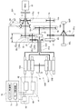
第二実施形態における駆動装置101は、図3に示すように、入力軸11と、第一駆動軸112と、第二駆動軸13と、出力軸114と、増速機構120と、二重ロータ型モータ30と、ドグクラッチ機構150と、駆動軸ロック機構61と、パーキングロック機構65と、制御装置70とを備えて構成される。ここで、第一実施形態と実質的に同一の構成については、図3において同一の符号を付して表記し、詳細な説明を省略する。
<Second embodiment>
(1. Overall configuration of drive device 101)
As shown in FIG. 3, the drive device 101 in the second embodiment includes an input shaft 11, a first drive shaft 112, a second drive shaft 13, an output shaft 114, a speed increasing mechanism 120, and a double rotor. The mold motor 30, the dog clutch mechanism 150, the drive shaft lock mechanism 61, the parking lock mechanism 65, and the control device 70 are configured. Here, about the structure substantially the same as 1st embodiment, the same code | symbol is attached | subjected and described in FIG. 3, and detailed description is abbreviate | omitted.
第一駆動軸112(本発明の「駆動軸」に相当する)は、ハウジングHに回転可能に支持され、入力軸11と同軸上に配置される。出力軸114は、ハイブリッド車両の駆動輪92L,92Rに、最終減速ギヤ17および差動機構91を介して連結される。また、入力軸11および出力軸114には、エンジン出力用ギヤ対115が設けられている。本実施形態において、エンジン出力用ギヤ対115は、駆動ギヤ115a(本発明の「第二ギヤ」に相当する)および従動ギヤ115b(本発明の「第一ギヤ」に相当する)により構成される歯車機構である。
The first drive shaft 112 (corresponding to the “drive shaft” of the present invention) is rotatably supported by the housing H and is arranged coaxially with the input shaft 11. Output shaft 114 is connected to drive wheels 92L, 92R of the hybrid vehicle via final reduction gear 17 and differential mechanism 91. The input shaft 11 and the output shaft 114 are provided with an engine output gear pair 115. In the present embodiment, the engine output gear pair 115 includes a drive gear 115a (corresponding to the “second gear” of the present invention) and a driven gear 115b (corresponding to the “first gear” of the present invention). It is a gear mechanism.
エンジン出力用ギヤ対115の駆動ギヤ115aは、入力軸11に固定される。エンジン出力用ギヤ対115の従動ギヤ115bは、出力軸114に対して相対回転可能に設けられ、且つ駆動ギヤ115aと噛合する。本実施形態において、エンジン出力用ギヤ対115は、後述するドグクラッチ機構150により従動ギヤ115bが出力軸114に選択的に連結されることによって、入力軸11と出力軸114との間で駆動力を伝達する。上記のように、出力軸114は、エンジン出力用ギヤ対115の従動ギヤ115bが設けられる支持軸である。
The drive gear 115 a of the engine output gear pair 115 is fixed to the input shaft 11. The driven gear 115b of the engine output gear pair 115 is provided to be rotatable relative to the output shaft 114, and meshes with the drive gear 115a. In the present embodiment, the engine output gear pair 115 generates a driving force between the input shaft 11 and the output shaft 114 by selectively connecting the driven gear 115b to the output shaft 114 by a dog clutch mechanism 150 described later. introduce. As described above, the output shaft 114 is a support shaft on which the driven gear 115b of the engine output gear pair 115 is provided.
(1−1.増速機構120)
増速機構120は、本実施形態において、2組のギヤ対により入力軸11と同方向の回転を第一駆動軸112に出力する二段増速機構としている。具体的には、増速機構120は、副軸21と、第一ギヤ対122(本発明の「第一伝達機構」に相当する)と、第二ギヤ対23(本発明の「第二伝達機構」に相当する)とを有する。第一ギヤ対122は、駆動ギヤ122aおよび従動ギヤ122bにより構成される歯車機構である。
(1-1. Speed increasing mechanism 120)
In this embodiment, the speed increasing mechanism 120 is a two-stage speed increasing mechanism that outputs rotation in the same direction as the input shaft 11 to the first drive shaft 112 by two pairs of gears. Specifically, the speed increasing mechanism 120 includes a countershaft 21, a first gear pair 122 (corresponding to the “first transmission mechanism” of the present invention), and a second gear pair 23 (“second transmission of the present invention”). Corresponding to “mechanism”). The first gear pair 122 is a gear mechanism that includes a drive gear 122a and a driven gear 122b.
第一ギヤ対122の駆動ギヤ122aは、入力軸11に固定される。本実施形態において、駆動ギヤ122aは、エンジン出力用ギヤ対115の駆動ギヤ115aと同一部材である。つまり、エンジン出力用ギヤ対115の駆動ギヤ115aは、増速機構120に駆動力を入力する伝達要素として兼用される。第一ギヤ対122の従動ギヤ122bは、副軸21に固定され、且つ駆動ギヤ122aと噛合する。このような構成により、増速機構120は、入力軸11と第一駆動軸112が同方向に回転するように、両軸間の駆動力の伝達を可能とする。
The drive gear 122 a of the first gear pair 122 is fixed to the input shaft 11. In the present embodiment, the drive gear 122a is the same member as the drive gear 115a of the engine output gear pair 115. That is, the drive gear 115 a of the engine output gear pair 115 is also used as a transmission element for inputting a driving force to the speed increasing mechanism 120. The driven gear 122b of the first gear pair 122 is fixed to the auxiliary shaft 21 and meshes with the drive gear 122a. With such a configuration, the speed increasing mechanism 120 enables transmission of the driving force between the two shafts so that the input shaft 11 and the first driving shaft 112 rotate in the same direction.
(1−2.ドグクラッチ機構150)
ドグクラッチ機構150は、出力軸114に対して相対回転可能に設けられたエンジン出力用ギヤ対115の従動ギヤ115b(122a)を、出力軸114に対して選択的に連結する断接機構である。ドグクラッチ機構150が従動ギヤ115bを出力軸114に対して連結した接続状態では、入力軸11および出力軸14は、エンジン出力用ギヤ対115により機械的に連結された状態となり、駆動ギヤ115aおよび従動ギヤ115bにより構成されるギヤ比に基づいて、相互に駆動力を伝達可能な状態となる。
(1-2. Dog clutch mechanism 150)
The dog clutch mechanism 150 is a connection / disconnection mechanism that selectively couples the driven gear 115 b (122 a) of the engine output gear pair 115 provided to be rotatable relative to the output shaft 114 to the output shaft 114. In the connected state where the dog clutch mechanism 150 connects the driven gear 115b to the output shaft 114, the input shaft 11 and the output shaft 14 are mechanically connected by the engine output gear pair 115, and the drive gear 115a and the driven gear 115 are driven. Based on the gear ratio constituted by the gear 115b, the driving force can be transmitted to each other.
これに対して、ドグクラッチ機構150が従動ギヤ115bを出力軸114に対して連結しない切断状態では、入力軸11および出力軸14は、機械的に連結されていない状態となり、互いに独立して回転可能となる。よって、ドグクラッチ機構150の切断状態では、入力軸11と出力軸14との間では、直接的に駆動力が伝達されない。
In contrast, in a disconnected state where the dog clutch mechanism 150 does not connect the driven gear 115b to the output shaft 114, the input shaft 11 and the output shaft 14 are not mechanically connected and can rotate independently of each other. It becomes. Therefore, when the dog clutch mechanism 150 is in the disconnected state, the driving force is not directly transmitted between the input shaft 11 and the output shaft 14.
ドグクラッチ機構150は、クラッチハブ151と、スリーブ152と、クラッチリング153とを有する。クラッチハブ151は、従動ギヤ115bが設けられた支持軸である出力軸114に固定され、出力軸114と一体的に回転する。クラッチハブ151の外周面には、出力軸114の軸方向に延在する外歯スプラインが形成されている。
The dog clutch mechanism 150 includes a clutch hub 151, a sleeve 152, and a clutch ring 153. The clutch hub 151 is fixed to the output shaft 114 which is a support shaft provided with the driven gear 115b, and rotates integrally with the output shaft 114. An external spline extending in the axial direction of the output shaft 114 is formed on the outer peripheral surface of the clutch hub 151.
スリーブ152の内周面には、クラッチハブ151の外歯スプラインと摺動可能に係合する内歯スプラインが形成されている。これにより、スリーブ152は、クラッチハブ151に対して相対回転不能に且つ出力軸114(従動ギヤ115bが設けられた支持軸)の軸方向に相対移動可能にクラッチハブ151に嵌合される。
On the inner peripheral surface of the sleeve 152, an internal spline that is slidably engaged with an external spline of the clutch hub 151 is formed. As a result, the sleeve 152 is fitted to the clutch hub 151 so as not to rotate relative to the clutch hub 151 and to be relatively movable in the axial direction of the output shaft 114 (support shaft provided with the driven gear 115b).
クラッチリング153は、本実施形態において、エンジン出力用ギヤ対115の従動ギヤ115bに一体的に固定される。クラッチリング153は、スリーブ152の軸方向位置に応じてスリーブ152と係脱可能に噛合する。このような構成により、ドグクラッチ機構150は、スリーブ152の軸方向の移動制御によってエンジン出力用ギヤ対115を介して、入力軸11と出力軸114との間で駆動力を伝達可能とする。
In this embodiment, the clutch ring 153 is integrally fixed to the driven gear 115b of the engine output gear pair 115. The clutch ring 153 meshes with the sleeve 152 in a detachable manner according to the axial position of the sleeve 152. With such a configuration, the dog clutch mechanism 150 can transmit a driving force between the input shaft 11 and the output shaft 114 via the engine output gear pair 115 by movement control of the sleeve 152 in the axial direction.
(2.駆動装置の動作、同期制御、回生制御)
駆動装置101の動作、同期制御、および回生制御については、第一実施形態と実質的に同一であるため、詳細な説明を省略する。ここで、第二実施形態の駆動装置101は、エンジン出力用ギヤ対115のうち支持軸に対して相対回転可能な従動ギヤ115bが出力軸114に設けられる。そのため、上述したように、断接機構であるドグクラッチ機構150は、出力軸114側に設けられる。
(2. Drive device operation, synchronous control, regenerative control)
About operation | movement of a drive device 101, synchronous control, and regenerative control, since it is substantially the same as 1st embodiment, detailed description is abbreviate | omitted. Here, in the drive device 101 of the second embodiment, the output shaft 114 is provided with a driven gear 115b that can rotate relative to the support shaft in the engine output gear pair 115. Therefore, as described above, the dog clutch mechanism 150 that is a connection / disconnection mechanism is provided on the output shaft 114 side.
このような構成においても、第一実施形態と同様に、同期制御を行うことが可能である。より詳細には、同期制御は、従動ギヤ115bが所定の回転数となるように従動ギヤ115bに駆動力を伝達することで行われる。本実施形態において、モータ制御部72は、ドグクラッチ機構150が接続状態にされる場合に、二重ロータ型モータ30のインナロータ33の回転数を制御することによって、増速機構20および駆動ギヤ115a(112a)を介して従動ギヤ115bに駆動力を伝達する。これにより、モータ制御部72は、出力軸114(従動ギヤ115bが設けられた支持軸)の回転数とエンジン出力用ギヤ対115の従動ギヤ115bの回転数とを同期させる。
Even in such a configuration, the synchronization control can be performed as in the first embodiment. More specifically, the synchronization control is performed by transmitting a driving force to the driven gear 115b so that the driven gear 115b has a predetermined rotation speed. In the present embodiment, the motor control unit 72 controls the speed increasing mechanism 20 and the drive gear 115a (by controlling the number of rotations of the inner rotor 33 of the double rotor type motor 30 when the dog clutch mechanism 150 is in the connected state. The driving force is transmitted to the driven gear 115b via 112a). Thereby, the motor control unit 72 synchronizes the rotation speed of the output shaft 114 (support shaft provided with the driven gear 115b) and the rotation speed of the driven gear 115b of the engine output gear pair 115.
(3.第二実施形態の構成による効果)
上述した駆動装置101は、第一実施形態と同様の効果を奏する。また、第二実施形態の駆動装置101において、第一駆動軸112は、入力軸11と同軸上に配置される。これにより、駆動装置101における入力軸11の径方向の体格が小さくなる。よって、第一駆動軸112を入力軸11と平行に配置した構成と比較して、車両における低い位置に駆動装置101を搭載することができる。従って、車両の低重心化が図られ、車両の走行性を向上できる。
(3. Effects of the configuration of the second embodiment)
The drive device 101 described above has the same effect as the first embodiment. In the drive device 101 of the second embodiment, the first drive shaft 112 is disposed coaxially with the input shaft 11. Thereby, the physique of the radial direction of the input shaft 11 in the drive device 101 becomes small. Therefore, the drive device 101 can be mounted at a lower position in the vehicle as compared with the configuration in which the first drive shaft 112 is arranged in parallel with the input shaft 11. Therefore, the center of gravity of the vehicle can be lowered and the traveling performance of the vehicle can be improved.
また、エンジン出力用ギヤ対115の駆動ギヤ115aは、入力軸11に固定され、且つ増速機構120に駆動力を入力する伝達要素(駆動ギヤ122a)として兼用される。これにより、駆動装置101における部品点数を低減できる。さらに、駆動装置101における入力軸11の軸方向の体格が小さくなり、装置全体としての小型化を図ることができる。
Further, the drive gear 115a of the engine output gear pair 115 is fixed to the input shaft 11, and is also used as a transmission element (drive gear 122a) for inputting a driving force to the speed increasing mechanism 120. Thereby, the number of parts in the drive device 101 can be reduced. Further, the size of the input shaft 11 in the drive device 101 in the axial direction is reduced, and the overall size of the device can be reduced.
<第三実施形態>
(1.駆動装置201の全体構成)
第三実施形態における駆動装置201は、図4に示すように、入力軸211と、第一駆動軸12と、第二駆動軸13と、出力軸14と、増速機構220と、二重ロータ型モータ30と、ドグクラッチ機構50と、駆動軸ロック機構61と、パーキングロック機構65と、制御装置70とを備えて構成される。ここで、第一実施形態と実質的に同一の構成については、図4において同一の符号を付して表記し、詳細な説明を省略する。
<Third embodiment>
(1. Overall configuration of drive device 201)
As shown in FIG. 4, the drive device 201 in the third embodiment includes an input shaft 211, a first drive shaft 12, a second drive shaft 13, an output shaft 14, a speed increasing mechanism 220, and a double rotor. The die motor 30, the dog clutch mechanism 50, the drive shaft lock mechanism 61, the parking lock mechanism 65, and the control device 70 are configured. Here, about the structure substantially the same as 1st embodiment, the same code | symbol is attached | subjected and described in FIG. 4, and detailed description is abbreviate | omitted.
(1−1.増速機構220)
ここで、第一実施形態において、駆動装置1の増速機構20は、2組のギヤ対を有する二段増速機構である。これに対して、第三実施形態の増速機構220は、遊星歯車機構を採用する。具体的には、駆動装置201は、図4に示すように、遊星歯車機構である増速機構220を備える。増速機構220は、サンギヤ221と、複数のプラネタリギヤ222と、リングギヤ223と、キャリア224とを有する。
(1-1. Speed increasing mechanism 220)
Here, in the first embodiment, the speed increasing mechanism 20 of the drive device 1 is a two-stage speed increasing mechanism having two pairs of gears. On the other hand, the speed increasing mechanism 220 of the third embodiment employs a planetary gear mechanism. Specifically, as shown in FIG. 4, the drive device 201 includes a speed increasing mechanism 220 that is a planetary gear mechanism. The speed increasing mechanism 220 includes a sun gear 221, a plurality of planetary gears 222, a ring gear 223, and a carrier 224.
サンギヤ221は、第一駆動軸12に固定され、第一駆動軸12と一体的に回転する。複数のプラネタリギヤ222は、サンギヤ221の外周側に配置され、サンギヤ221と噛合する。リングギヤ223は、ハウジングHに回転不能に固定され、内周側に位置する複数のプラネタリギヤ222と噛合する。キャリア224は、複数のプラネタリギヤ222を回転可能に支持する。キャリア224は、入力軸211に固定され、入力軸211と一体的に回転する。
The sun gear 221 is fixed to the first drive shaft 12 and rotates integrally with the first drive shaft 12. The plurality of planetary gears 222 are disposed on the outer peripheral side of the sun gear 221 and mesh with the sun gear 221. The ring gear 223 is fixed to the housing H so as not to rotate, and meshes with a plurality of planetary gears 222 located on the inner peripheral side. The carrier 224 supports the plurality of planetary gears 222 in a rotatable manner. The carrier 224 is fixed to the input shaft 211 and rotates integrally with the input shaft 211.
(2.駆動装置の動作、同期制御、回生制御)
このような構成からなる増速機構220は、入力軸211を介してエンジン81が出力する駆動力を入力すると、先ずキャリア224がエンジン81と同方向に回転する。そうすると、複数のプラネタリギヤ222は、サンギヤ221の回転軸線周りに且つ入力軸211と同一方向に公転する。このとき、プラネタリギヤ222は、ハウジングHに固定されたリングギヤ223と噛合するため、プラネタリギヤ222の回転軸線周りに且つ入力軸211と逆方向に自転する。
(2. Drive device operation, synchronous control, regenerative control)
In the speed increasing mechanism 220 having such a configuration, when the driving force output from the engine 81 is input via the input shaft 211, the carrier 224 first rotates in the same direction as the engine 81. Then, the plurality of planetary gears 222 revolve around the rotation axis of the sun gear 221 and in the same direction as the input shaft 211. At this time, since the planetary gear 222 meshes with the ring gear 223 fixed to the housing H, the planetary gear 222 rotates around the rotation axis of the planetary gear 222 and in the direction opposite to the input shaft 211.
複数のプラネタリギヤ222に噛合するサンギヤ221は、プラネタリギヤ222とは逆方向に回転する。即ち、サンギヤ221は、入力軸211と同一方向に回転する。これにより、各要素により構成されるギヤ比に応じて増速された駆動力が第一駆動軸12に出力される。その他、駆動装置101の動作、同期制御、および回生制御については、第一実施形態と実質的に同一であるため、詳細な説明を省略する。
The sun gear 221 that meshes with the plurality of planetary gears 222 rotates in the opposite direction to the planetary gear 222. That is, the sun gear 221 rotates in the same direction as the input shaft 211. Thereby, the driving force increased according to the gear ratio constituted by each element is output to the first drive shaft 12. In addition, since operation | movement of the drive device 101, synchronous control, and regenerative control are substantially the same as 1st embodiment, detailed description is abbreviate | omitted.
(3.第三実施形態の構成による効果)
上述した駆動装置201は、遊星歯車機構である増速機構220を備え、第一実施形態と同様の効果を奏する。また、駆動装置201は、第二実施形態の駆動装置101と同様に、入力軸211と第一駆動軸12とが同軸上に配置される。これにより、第三実施形態の駆動装置201は、第二実施形態の駆動装置201の当該構成による効果と同様の効果を奏する。
(3. Effects of the configuration of the third embodiment)
The drive device 201 described above includes a speed increasing mechanism 220 that is a planetary gear mechanism, and has the same effects as the first embodiment. In the drive device 201, the input shaft 211 and the first drive shaft 12 are arranged coaxially, similarly to the drive device 101 of the second embodiment. Thereby, the drive apparatus 201 of 3rd embodiment has an effect similar to the effect by the said structure of the drive apparatus 201 of 2nd embodiment.
<第四実施形態>
(1.駆動装置301の全体構成)
第四実施形態における駆動装置301は、図5に示すように、入力軸11と、第一駆動軸312と、第二駆動軸13と、出力軸14と、増速機構20と、二重ロータ型モータ30と、ドグクラッチ機構350と、駆動軸ロック機構61と、パーキングロック機構65と、制御装置70とを備えて構成される。ここで、第一実施形態と実質的に同一の構成については、図5において同一の符号を付して表記し、詳細な説明を省略する。
<Fourth embodiment>
(1. Overall configuration of drive device 301)
As shown in FIG. 5, the drive device 301 in the fourth embodiment includes an input shaft 11, a first drive shaft 312, a second drive shaft 13, an output shaft 14, a speed increasing mechanism 20, and a double rotor. The mold motor 30, the dog clutch mechanism 350, the drive shaft lock mechanism 61, the parking lock mechanism 65, and the control device 70 are configured. Here, about the structure substantially the same as 1st embodiment, the same code | symbol is attached | subjected and described in FIG. 5, and detailed description is abbreviate | omitted.
ここで、第一、第二、および第三実施形態において、駆動装置1,101,201は、入力軸11,211と出力軸14,114との間で駆動力を伝達可能とするエンジン出力用ギヤ対15,115を備える。これに対して、第四実施形態の駆動装置301は、モータ出力用ギヤ対316およびドグクラッチ機構350を用いて、第一駆動軸312と出力軸14との間で駆動力を伝達可能とすることによって、増速機構20により増速されたエンジン81の駆動力を出力軸14に出力可能する構成を採用する。
Here, in the first, second, and third embodiments, the driving devices 1, 101, 201 are for engine output that can transmit driving force between the input shafts 11, 211 and the output shafts 14, 114. Gear pairs 15 and 115 are provided. In contrast, the driving device 301 of the fourth embodiment enables transmission of driving force between the first driving shaft 312 and the output shaft 14 using the motor output gear pair 316 and the dog clutch mechanism 350. Thus, a configuration is adopted in which the driving force of the engine 81 accelerated by the speed increasing mechanism 20 can be output to the output shaft 14.
(1−1.モータ出力用ギヤ対316)
第一駆動軸312(本発明の「駆動軸」に相当する)は、ハウジングHに回転可能に支持され、入力軸11と平行に配置される。第二駆動軸13は、第一駆動軸312と同軸上に配置される。第二駆動軸13は、第一駆動軸312に対して相対回転可能に支持される。また、第二駆動軸13および出力軸14には、モータ出力用ギヤ対316が設けられている。本実施形態において、モータ出力用ギヤ対316は、駆動ギヤ316aおよび従動ギヤ316bにより構成される歯車機構である。モータ出力用ギヤ対316の駆動ギヤ316aは、第二駆動軸13に固定される。
(1-1. Motor output gear pair 316)
The first drive shaft 312 (corresponding to the “drive shaft” of the present invention) is rotatably supported by the housing H and is disposed in parallel with the input shaft 11. The second drive shaft 13 is disposed coaxially with the first drive shaft 312. The second drive shaft 13 is supported so as to be rotatable relative to the first drive shaft 312. The second drive shaft 13 and the output shaft 14 are provided with a motor output gear pair 316. In the present embodiment, the motor output gear pair 316 is a gear mechanism including a drive gear 316a and a driven gear 316b. The drive gear 316 a of the motor output gear pair 316 is fixed to the second drive shaft 13.
モータ出力用ギヤ対316の従動ギヤ316bは、出力軸14に固定され、且つ駆動ギヤ316aと噛合する。モータ出力用ギヤ対16は、第二駆動軸13と出力軸14との間で駆動力を伝達する。また、本実施形態において、モータ出力用ギヤ対316は、後述するドグクラッチ機構350により駆動ギヤ316aが第一駆動軸312に選択的に連結されることによって、第一駆動軸312と出力軸14との間で駆動力を伝達する。つまり、モータ出力用ギヤ対316は、増速機構20により増速されたエンジン81の駆動力を第一駆動軸312から出力軸14へと伝達する機能を有する。
The driven gear 316b of the motor output gear pair 316 is fixed to the output shaft 14 and meshes with the drive gear 316a. The motor output gear pair 16 transmits a driving force between the second drive shaft 13 and the output shaft 14. In the present embodiment, the motor output gear pair 316 includes a first drive shaft 312 and an output shaft 14 that are selectively connected to the first drive shaft 312 by a dog clutch mechanism 350 described later. The driving force is transmitted between the two. That is, the motor output gear pair 316 has a function of transmitting the driving force of the engine 81 accelerated by the speed increasing mechanism 20 from the first drive shaft 312 to the output shaft 14.
ここで、第二駆動軸13は、第一駆動軸312に対して相対回転可能に設けられる。よって、第二駆動軸13に固定されたモータ出力用ギヤ対316の駆動ギヤ316aは、第一駆動軸112に対して相対回転可能に設けられており、本発明の「第一ギヤ」に相当する。また、モータ出力用ギヤ対316の従動ギヤ316bは、出力軸14に固定され、且つ駆動ギヤ316aと噛合するように設けられており、本発明の「第二ギヤ」に相当する。
Here, the second drive shaft 13 is provided to be rotatable relative to the first drive shaft 312. Therefore, the drive gear 316a of the motor output gear pair 316 fixed to the second drive shaft 13 is provided to be rotatable relative to the first drive shaft 112, and corresponds to the “first gear” of the present invention. To do. The driven gear 316b of the motor output gear pair 316 is fixed to the output shaft 14 and is provided so as to mesh with the drive gear 316a, and corresponds to the “second gear” of the present invention.
(1−2.ドグクラッチ機構350)
ドグクラッチ機構350は、第一駆動軸112に対して相対回転可能に設けられたモータ出力用ギヤ対316の駆動ギヤ316aを、第一駆動軸112に対して選択的に連結する断接機構である。ドグクラッチ機構350が駆動ギヤ316aを第一駆動軸112に対して連結した接続状態では、第一駆動軸112および出力軸14は、モータ出力用ギヤ対316により機械的に連結された状態となり、駆動ギヤ316aおよび従動ギヤ316bにより構成されるギヤ比に基づいて、相互に駆動力を伝達可能な状態となる。
(1-2. Dog clutch mechanism 350)
The dog clutch mechanism 350 is a connection / disconnection mechanism that selectively couples the drive gear 316 a of the motor output gear pair 316 provided to be rotatable relative to the first drive shaft 112 to the first drive shaft 112. . In the connected state where the dog clutch mechanism 350 is connected to the first drive shaft 112, the first drive shaft 112 and the output shaft 14 are mechanically connected by the motor output gear pair 316, and the drive Based on the gear ratio constituted by the gear 316a and the driven gear 316b, the driving force can be transmitted to each other.
これに対して、ドグクラッチ機構350が駆動ギヤ316aを第一駆動軸112に対して連結しない切断状態では、第一駆動軸112および出力軸14は、機械的に連結されていない状態となり、互いに独立して回転可能となる。よって、ドグクラッチ機構350の切断状態では、第一駆動軸112と出力軸14との間では、直接的に駆動力が伝達されない。
On the other hand, in a disconnected state where the dog clutch mechanism 350 does not connect the drive gear 316a to the first drive shaft 112, the first drive shaft 112 and the output shaft 14 are not mechanically connected and are independent from each other. And can be rotated. Therefore, the driving force is not directly transmitted between the first drive shaft 112 and the output shaft 14 in the disconnected state of the dog clutch mechanism 350.
ドグクラッチ機構350は、クラッチハブ351と、スリーブ352と、クラッチリング353とを有する。クラッチハブ351は、駆動ギヤ316aを相対回転可能に支持する支持軸である第一駆動軸112に固定され、第一駆動軸112と一体的に回転する。クラッチハブ351の外周面には、第一駆動軸112の軸方向に延在する外歯スプラインが形成されている。
The dog clutch mechanism 350 includes a clutch hub 351, a sleeve 352, and a clutch ring 353. The clutch hub 351 is fixed to the first drive shaft 112 that is a support shaft that supports the drive gear 316 a so as to be relatively rotatable, and rotates integrally with the first drive shaft 112. On the outer peripheral surface of the clutch hub 351, an external spline extending in the axial direction of the first drive shaft 112 is formed.
スリーブ352の内周面には、クラッチハブ351の外歯スプラインと摺動可能に係合する内歯スプラインが形成されている。これにより、スリーブ352は、クラッチハブ351に対して相対回転不能に且つ第一駆動軸112の軸方向に相対移動可能にクラッチハブ351に嵌合される。
On the inner peripheral surface of the sleeve 352, an internal spline that is slidably engaged with an external spline of the clutch hub 351 is formed. As a result, the sleeve 352 is fitted to the clutch hub 351 such that the sleeve 352 cannot rotate relative to the clutch hub 351 and can move relative to the axial direction of the first drive shaft 112.
クラッチリング353は、本実施形態において、モータ出力用ギヤ対316の駆動ギヤ316aに一体的に固定される。クラッチリング353は、スリーブ352の軸方向位置に応じてスリーブ352と係脱可能に噛合する。このような構成により、ドグクラッチ機構350は、スリーブ352の軸方向の移動制御によってモータ出力用ギヤ対316を介して、第一駆動軸112と出力軸14との間で駆動力を伝達可能とする。
In the present embodiment, the clutch ring 353 is integrally fixed to the drive gear 316a of the motor output gear pair 316. The clutch ring 353 meshes with the sleeve 352 so as to be detachable in accordance with the axial position of the sleeve 352. With such a configuration, the dog clutch mechanism 350 can transmit a driving force between the first drive shaft 112 and the output shaft 14 via the motor output gear pair 316 by the axial movement control of the sleeve 352. .
(2.駆動装置の動作、同期制御、回生制御)
駆動装置301の動作、同期制御、および回生制御については、第一実施形態と実質的に同一であるため、詳細な説明を省略する。ここで、第四実施形態の駆動装置301において、モータ出力用ギヤ対316は、二重ロータ型モータ30の駆動力を出力軸14に伝達するとともに、ドグクラッチ機構350の作動によりエンジン81の駆動力を出力軸14に伝達可能とする。
(2. Drive device operation, synchronous control, regenerative control)
About operation | movement of a drive device 301, synchronous control, and regenerative control, since it is substantially the same as 1st embodiment, detailed description is abbreviate | omitted. Here, in the driving device 301 of the fourth embodiment, the motor output gear pair 316 transmits the driving force of the double rotor type motor 30 to the output shaft 14 and the driving force of the engine 81 by the operation of the dog clutch mechanism 350. Can be transmitted to the output shaft 14.
(3.第四実施形態の構成による効果)
上述した駆動装置301は、第一実施形態と同様の効果を奏する。また、駆動装置301は、上述したように、モータ出力用ギヤ対316がエンジン81の駆動力を出力軸14に伝達可能とする。よって、第四実施形態の駆動装置301は、モータ出力用ギヤ対316と別にエンジン出力用ギヤ対を設けた構成と比較して部品点数を低減できる。
(3. Effects of the configuration of the fourth embodiment)
The drive device 301 described above has the same effect as the first embodiment. Further, as described above, the driving device 301 enables the motor output gear pair 316 to transmit the driving force of the engine 81 to the output shaft 14. Therefore, the drive device 301 of the fourth embodiment can reduce the number of parts compared to the configuration in which the engine output gear pair is provided separately from the motor output gear pair 316.
また、駆動装置301の構成によると、ドグクラッチ機構350の接続状態により、インナロータ33がアウタロータ32と機械的に連結され、二重ロータ型モータ30は、両部材が一体的に回転するカップリング状態となる。これにより、車両の走行状態に応じた駆動装置301の動作において、二重ロータ型モータ30をカップリング状態とする必要がある場合の消費電力を低減できる。
Further, according to the configuration of the drive device 301, the inner rotor 33 is mechanically coupled to the outer rotor 32 according to the connection state of the dog clutch mechanism 350, and the double rotor type motor 30 has a coupling state in which both members rotate integrally. Become. Thereby, in operation | movement of the drive device 301 according to the driving | running | working state of a vehicle, the power consumption when it is necessary to make the double rotor type motor 30 into a coupling state can be reduced.
<第五実施形態>
(1.駆動装置401の全体構成)
第五実施形態における駆動装置401は、図6に示すように、入力軸11と、第一駆動軸12と、第二駆動軸13と、出力軸14と、エンジン出力用ギヤユニット415と、増速機構20と、二重ロータ型モータ30と、電力供給装置40と、ドグクラッチ機構50と、駆動軸ロック機構61と、パーキングロック機構65と、制御装置70とを備えて構成される。ここで、第一実施形態と実質的に同一の構成については、図6において同一の符号を付して表記し、詳細な説明を省略する。
<Fifth embodiment>
(1. Overall configuration of drive device 401)
As shown in FIG. 6, the drive device 401 according to the fifth embodiment includes an input shaft 11, a first drive shaft 12, a second drive shaft 13, an output shaft 14, an engine output gear unit 415, The speed mechanism 20, the double rotor type motor 30, the power supply device 40, the dog clutch mechanism 50, the drive shaft lock mechanism 61, the parking lock mechanism 65, and the control device 70 are configured. Here, about the structure substantially the same as 1st embodiment, the same code | symbol is attached | subjected and described in FIG. 6, and detailed description is abbreviate | omitted.
(1−1.エンジン出力用ギヤユニット415)
エンジン出力用ギヤユニット415は、中間軸415aと、第一駆動ギヤ415b(本発明の「第一ギヤ」に相当する)と、従動ギヤ415c(本発明の「第二ギヤ」に相当する)と、第二駆動ギヤ415d(本発明の「第三ギヤ」に相当する)とを有する。
(1-1. Gear unit for engine output 415)
The engine output gear unit 415 includes an intermediate shaft 415a, a first drive gear 415b (corresponding to the “first gear” of the present invention), and a driven gear 415c (corresponding to the “second gear” of the present invention). And a second drive gear 415d (corresponding to the “third gear” of the present invention).
中間軸415aは、ハウジングHに回転可能に支持され、入力軸11と平行に配置される。第一駆動ギヤ415bは、本実施形態において、入力軸11に対して相対回転可能に設けられる。従動ギヤ415cは、中間軸415aに固定され、且つ第一駆動ギヤ415bと噛合する。第二駆動ギヤ415dは、中間軸415aに固定される。第二駆動ギヤ415d、出力軸14と駆動輪92L,92Rとの間に介在する差動機構91のデフリングギヤ91aと、最終減速ギヤ17が当該デフリングギヤ91aと噛合する位相とは別の位相で噛合する。
The intermediate shaft 415 a is rotatably supported by the housing H and is disposed in parallel with the input shaft 11. In the present embodiment, the first drive gear 415 b is provided to be rotatable relative to the input shaft 11. The driven gear 415c is fixed to the intermediate shaft 415a and meshes with the first drive gear 415b. The second drive gear 415d is fixed to the intermediate shaft 415a. The second drive gear 415d, the differential shaft 91 of the differential mechanism 91 interposed between the output shaft 14 and the drive wheels 92L and 92R, and the phase where the final reduction gear 17 meshes with the differential ring gear 91a are different from each other. Mesh.
エンジン出力用ギヤユニット415は、ドグクラッチ機構50により第一駆動ギヤ415bが入力軸11に選択的に連結されることによって、入力軸11と差動機構91との間で駆動力を伝達する。このような構成により、中間軸415aは、ドグクラッチ機構50が接続状態にある場合に、入力軸11の回転方向とは逆方向に回転する。よって、例えば入力軸11が時計回りに回転している場合には、第一駆動軸12、第二駆動軸13、および差動機構91のデフリングギヤ91aは、入力軸11と同方向である時計回りにそれぞれ回転する。
The engine output gear unit 415 transmits a driving force between the input shaft 11 and the differential mechanism 91 by selectively connecting the first drive gear 415 b to the input shaft 11 by the dog clutch mechanism 50. With such a configuration, the intermediate shaft 415a rotates in the direction opposite to the rotation direction of the input shaft 11 when the dog clutch mechanism 50 is in the connected state. Therefore, for example, when the input shaft 11 rotates clockwise, the first drive shaft 12, the second drive shaft 13, and the diff ring gear 91 a of the differential mechanism 91 are in the same direction as the input shaft 11. Each rotates around.
(2.駆動装置の動作、同期制御、回生制御)
駆動装置401の動作、同期制御、および回生制御については、第一実施形態と実質的に同一であるため、詳細な説明を省略する。ここで、第五実施形態の駆動装置401において、エンジン出力用ギヤユニット415は、エンジン81の駆動力を直接的に差動機構91に入力可能に構成される。つまり、エンジン81の駆動力による走行状態(ENG走行、HV走行)において、エンジン81の駆動力は、出力軸14を経由することなく差動機構91に伝達される。
(2. Drive device operation, synchronous control, regenerative control)
About operation | movement of a drive device 401, synchronous control, and regeneration control, since it is substantially the same as 1st embodiment, detailed description is abbreviate | omitted. Here, in the driving device 401 of the fifth embodiment, the engine output gear unit 415 is configured to be able to input the driving force of the engine 81 directly to the differential mechanism 91. That is, in the traveling state (ENG traveling, HV traveling) by the driving force of the engine 81, the driving force of the engine 81 is transmitted to the differential mechanism 91 without passing through the output shaft 14.
(3.第五実施形態の構成による効果)
上述した駆動装置401は、第一実施形態と同様の効果を奏する。また、駆動装置401は、上述したように、エンジン出力用ギヤユニット415がエンジン81の駆動力を差動機構91へと直接的に伝達可能とする。よって、出力軸14をエンジン81の駆動力が経由する構成と比較して、より効率的に駆動力を伝達することができる。
(3. Effects of the configuration of the fifth embodiment)
The drive device 401 described above has the same effect as the first embodiment. Further, as described above, the drive device 401 enables the engine output gear unit 415 to directly transmit the driving force of the engine 81 to the differential mechanism 91. Therefore, the driving force can be transmitted more efficiently than the configuration in which the driving force of the engine 81 passes through the output shaft 14.
<第六実施形態>
第六実施形態における駆動装置501は、図7に示すように、入力軸11と、第一駆動軸512と、第二駆動軸513と、出力軸14と、増速機構20と、二重ロータ型モータ530と、電力供給装置40と、ドグクラッチ機構50と、駆動軸ロック機構61と、パーキングロック機構65と、制御装置70とを備えて構成される。ここで、第一実施形態と実質的に同一の構成については、図7において同一の符号を付して表記し、詳細な説明を省略する。
<Sixth embodiment>
As shown in FIG. 7, the drive device 501 in the sixth embodiment includes an input shaft 11, a first drive shaft 512, a second drive shaft 513, an output shaft 14, a speed increasing mechanism 20, and a double rotor. The mold motor 530, the power supply device 40, the dog clutch mechanism 50, the drive shaft lock mechanism 61, the parking lock mechanism 65, and the control device 70 are configured. Here, about the structure substantially the same as 1st embodiment, the same code | symbol is attached | subjected and described in FIG. 7, and detailed description is abbreviate | omitted.
ここで、第一実施形態において、二重ロータ型モータ30は、外周側から順にステータ31(固定子)、アウタロータ32(第一回転子)、およびインナロータ33(第二回転子)を配置して構成される。これに対して、二重ロータ型モータは、内周側から順に固定子、第一回転子、および第二回転子を配置して構成されてもよい。具体的には、駆動装置501の二重ロータ型モータ530は、図7に示すように、各部材が第一実施形態とは逆順に配置される。
Here, in the first embodiment, the double rotor type motor 30 includes a stator 31 (stator), an outer rotor 32 (first rotor), and an inner rotor 33 (second rotor) arranged in order from the outer peripheral side. Composed. On the other hand, the double rotor type motor may be configured by arranging a stator, a first rotor, and a second rotor in order from the inner peripheral side. Specifically, as shown in FIG. 7, in the double rotor type motor 530 of the driving device 501, the members are arranged in the reverse order of the first embodiment.
二重ロータ型モータ530は、ステータ531(本発明の「固定子」に相当する)と、インナロータ532(本発明の「第一回転子」に相当する)と、アウタロータ533(本発明の「第二回転子」に相当する)とを有する。インナロータ532は、第二駆動軸513に一体的に連結される。アウタロータ533は、第一駆動軸512に一体的に連結される。なお、本実施形態において、第一回転子(インナロータ532)が第二回転子(アウタロータ533)の内周側に配置されることから、第二駆動軸513は、図7に示すように、第一駆動軸512の内周側に相対回転可能に配置される。このような構成からなる本実施形態の駆動装置601は、第一実施形態と同様の効果を奏する。
The double rotor type motor 530 includes a stator 531 (corresponding to “stator” of the present invention), an inner rotor 532 (corresponding to “first rotor” of the present invention), and an outer rotor 533 (“first rotor” of the present invention). Corresponding to “two rotors”. The inner rotor 532 is integrally connected to the second drive shaft 513. The outer rotor 533 is integrally connected to the first drive shaft 512. In the present embodiment, since the first rotor (inner rotor 532) is disposed on the inner peripheral side of the second rotor (outer rotor 533), the second drive shaft 513 is configured as shown in FIG. Arranged on the inner peripheral side of one drive shaft 512 to be relatively rotatable. The drive device 601 of the present embodiment having such a configuration has the same effects as the first embodiment.
<第七実施形態>
第七実施形態における駆動装置601は、図8に示すように、入力軸11と、第一駆動軸12と、第二駆動軸13と、出力軸14と、増速機構20と、二重ロータ型モータ30と、電力供給装置40と、ドグクラッチ機構50と、駆動軸ロック機構61と、パーキングロック機構65と、制御装置70とを備えて構成される。ここで、第一実施形態と実質的に同一の構成については、図8において同一の符号を付して表記し、詳細な説明を省略する。
<Seventh embodiment>
As shown in FIG. 8, the drive device 601 in the seventh embodiment includes an input shaft 11, a first drive shaft 12, a second drive shaft 13, an output shaft 14, a speed increasing mechanism 20, and a double rotor. The mold motor 30, the power supply device 40, the dog clutch mechanism 50, the drive shaft lock mechanism 61, the parking lock mechanism 65, and the control device 70 are configured. Here, about the structure substantially the same as 1st embodiment, the same code | symbol is attached | subjected and described in FIG. 8, and detailed description is abbreviate | omitted.
ここで、第一実施形態において、駆動装置1は、エンジン出力用ギヤ対15およびモータ出力用ギヤ対16を備える。これに対して、エンジン出力用ギヤ対15の従動ギヤ15bとモータ出力用ギヤ対16の従動ギヤ16bとを兼用とする構成としてもよい。具体的には、駆動装置601は、図8に示すように、従動ギヤ615b、616bが兼用されたエンジン出力用ギヤ対615およびモータ出力用ギヤ対616を備える。
Here, in the first embodiment, the drive device 1 includes an engine output gear pair 15 and a motor output gear pair 16. In contrast, the driven gear 15b of the engine output gear pair 15 and the driven gear 16b of the motor output gear pair 16 may be combined. Specifically, as shown in FIG. 8, the drive device 601 includes an engine output gear pair 615 and a motor output gear pair 616 in which the driven gears 615 b and 616 b are also used.
エンジン出力用ギヤ対615は、駆動ギヤ615a(本発明の「第一ギヤ」に相当する)および従動ギヤ615b(本発明の「第二ギヤ」に相当する)により構成される歯車機構である。エンジン出力用ギヤ対615の駆動ギヤ615aは、入力軸11に対して相対回転可能に設けられる。エンジン出力用ギヤ対615の従動ギヤ615bは、出力軸14に固定され、且つ駆動ギヤ615aと噛合する。エンジン出力用ギヤ対615は、ドグクラッチ機構50により駆動ギヤ615aが入力軸11に選択的に連結されることによって、入力軸11と出力軸14との間で駆動力を伝達する。
The engine output gear pair 615 is a gear mechanism including a drive gear 615a (corresponding to the “first gear” of the present invention) and a driven gear 615b (corresponding to the “second gear” of the present invention). The drive gear 615 a of the engine output gear pair 615 is provided to be rotatable relative to the input shaft 11. The driven gear 615b of the engine output gear pair 615 is fixed to the output shaft 14 and meshes with the drive gear 615a. The engine output gear pair 615 transmits the driving force between the input shaft 11 and the output shaft 14 by selectively connecting the drive gear 615 a to the input shaft 11 by the dog clutch mechanism 50.
モータ出力用ギヤ対616は、駆動ギヤ616aおよび従動ギヤ616bにより構成される歯車機構である。モータ出力用ギヤ対616の駆動ギヤ616aは、第二駆動軸13に固定される。モータ出力用ギヤ対616の従動ギヤ616bは、出力軸14に固定され、且つ駆動ギヤ616aと噛合する。本実施形態において、従動ギヤ616bは、エンジン出力用ギヤ対615の従動ギヤ615bと同一部材である。つまり、エンジン出力用ギヤ対615の駆動ギヤ615aは、モータ出力用ギヤ対616に兼用される。
The motor output gear pair 616 is a gear mechanism including a drive gear 616a and a driven gear 616b. The drive gear 616 a of the motor output gear pair 616 is fixed to the second drive shaft 13. The driven gear 616b of the motor output gear pair 616 is fixed to the output shaft 14 and meshes with the drive gear 616a. In the present embodiment, the driven gear 616b is the same member as the driven gear 615b of the engine output gear pair 615. That is, the drive gear 615 a of the engine output gear pair 615 is also used as the motor output gear pair 616.
このような構成からなる駆動装置601によると、エンジン出力用ギヤ対615およびモータ出力用ギヤ対616が異なる軸方向位置に配置される場合と比較して、部品点数を低減できるとともに、駆動装置601の軸方向の体格を小さくできる。これにより、装置全体としての小型化を図ることができる。
According to the drive device 601 having such a configuration, the number of parts can be reduced and the drive device 601 can be reduced as compared with the case where the engine output gear pair 615 and the motor output gear pair 616 are arranged at different axial positions. The physique in the axial direction can be reduced. Thereby, size reduction as the whole apparatus can be achieved.
<実施形態の変形態様>
第一、第二、第四〜第七実施形態において、二段増速機構である増速機構20,120は、第一伝達機構および第二伝達機構として、第一ギヤ対22,122および第二ギヤ対23,123を有する。これに対して、第一伝達機構および第二伝達機構は、駆動力をそれぞれ反転しながら伝達可能な構成であれば、歯車機構の他に種々の態様を採用できる。例えば、増速機構は、第一伝達機構および第二伝達機構として、スプロケットとチェーン、プーリと無端ベルトなどの組み合わせにより駆動力を二段階で増速しながら伝達してもよい。
<Modification of Embodiment>
In the first, second, and fourth to seventh embodiments, the speed increasing mechanisms 20 and 120, which are two-stage speed increasing mechanisms, are the first gear pair 22 and 122 and the second speed increasing mechanism. Two gear pairs 23 and 123 are provided. On the other hand, the first transmission mechanism and the second transmission mechanism can employ various modes in addition to the gear mechanism as long as the first transmission mechanism and the second transmission mechanism can transmit the driving force while reversing each. For example, as the first transmission mechanism and the second transmission mechanism, the speed increasing mechanism may transmit the driving force while increasing the speed in two stages by a combination of a sprocket and a chain, a pulley and an endless belt, or the like.
また、駆動装置1〜601は、断接機構としてドグクラッチ機構50,150,350を採用する。これに対して、駆動装置1〜601は、シンクロ機構を有する断接機構や、湿式多板クラッチ機構を適用してもよい。このような構成においても、実施形態と同様に、入力軸11と出力軸14,114との間で駆動力を選択的に伝達可能とすることができる。但し、部品点数などの観点からは、実施形態に例示したように、ドグクラッチ機構50,150,350の採用が好適である。
Further, the driving devices 1 to 601 employ dog clutch mechanisms 50, 150, and 350 as connection / disconnection mechanisms. On the other hand, the connecting devices 1 to 601 may apply a connection / disconnection mechanism having a synchro mechanism or a wet multi-plate clutch mechanism. Even in such a configuration, the driving force can be selectively transmitted between the input shaft 11 and the output shafts 14 and 114 as in the embodiment. However, from the viewpoint of the number of parts and the like, it is preferable to employ the dog clutch mechanisms 50, 150, and 350 as illustrated in the embodiment.
また、第一、第三、第六、実施形態において、断接機構(ドグクラッチ機構50)は、入力軸11および出力軸14のうち第一ギヤ(駆動ギヤ15a)が設けられた支持軸である入力軸11側に設けられる。これに対して、断接機構は、第二実施形態のドグクラッチ機構150のように、出力軸14側に設けられる構成としてもよい。このような構成において、エンジン出力用ギヤ対は、出力軸14に対して相対回転可能に設けられる第一ギヤと、入力軸11に固定され且つ第一ギヤと噛合する第二ギヤとを有する。そして、断接機構は、上記の第一ギヤを出力軸14に対して選択的に連結する。
In the first, third, sixth, and embodiment, the connection / disconnection mechanism (dog clutch mechanism 50) is a support shaft provided with the first gear (drive gear 15a) of the input shaft 11 and the output shaft 14. Provided on the input shaft 11 side. On the other hand, the connection / disconnection mechanism may be provided on the output shaft 14 side as in the dog clutch mechanism 150 of the second embodiment. In such a configuration, the engine output gear pair includes a first gear provided to be rotatable relative to the output shaft 14 and a second gear fixed to the input shaft 11 and meshing with the first gear. The connection / disconnection mechanism selectively connects the first gear to the output shaft 14.
同様に、第四実施形態において、断接機構(ドグクラッチ機構350)は、出力軸14側に設けられる構成としてもよい。このような構成では、モータ出力用ギヤ対316とは別に第一駆動軸312および出力軸14にエンジン出力用ギヤ対が設けられ、且つエンジン出力用ギヤ対の従動ギヤ(本発明の「第一ギヤ」に相当する)が出力軸14に対して相対回転可能に設けられる構成となる。
Similarly, in the fourth embodiment, the connection / disconnection mechanism (dog clutch mechanism 350) may be provided on the output shaft 14 side. In such a configuration, an engine output gear pair is provided on the first drive shaft 312 and the output shaft 14 separately from the motor output gear pair 316, and the driven gear of the engine output gear pair (the “first output of the present invention” (Corresponding to “gear”) is provided to be rotatable relative to the output shaft 14.
さらに、第五実施形態においても、断接機構(ドグクラッチ機構50)は、中間軸415a側に設けられる構成としてもよい。このような構成では、エンジン出力用ギヤユニット415は、第一駆動ギヤ(本発明の「第二ギヤ」に相当する)が入力軸11に固定され、従動ギヤ(本発明の「第一ギヤ」に相当する)が中間軸415aに対して相対回転可能に設けられる。
Furthermore, also in the fifth embodiment, the connection / disconnection mechanism (dog clutch mechanism 50) may be provided on the intermediate shaft 415a side. In such a configuration, the engine output gear unit 415 has a first drive gear (corresponding to the “second gear” of the present invention) fixed to the input shaft 11 and a driven gear (the “first gear” of the present invention). Is provided so as to be relatively rotatable with respect to the intermediate shaft 415a.
上記のように、断接機構(ドグクラッチ機構50,150,350)が差動機構91側の支持軸に設けられる構成は、例えばエンジン81が休止された走行状態(EV走行)において、インナロータ33を用いた発電を要しない場合に、出力軸14の回転に伴うエンジン出力用ギヤ対の回転が抑制される点で有利である。一方で、実施形態において例示したように、断接機構(ドグクラッチ機構50,150,350)がエンジン81側の支持軸に設けられている構成は、例えば車両の停止状態において、インナロータ33を用いた発電を要する場合に、入力軸11の回転に伴うエンジン出力用ギヤ対の回転が抑制される点で有利である。
As described above, the connection / disconnection mechanism (dog clutch mechanism 50, 150, 350) is provided on the support shaft on the differential mechanism 91 side. For example, in the traveling state in which the engine 81 is stopped (EV traveling), the inner rotor 33 is When the power generation used is not required, it is advantageous in that the rotation of the engine output gear pair accompanying the rotation of the output shaft 14 is suppressed. On the other hand, as exemplified in the embodiment, the configuration in which the connecting / disconnecting mechanism (dog clutch mechanism 50, 150, 350) is provided on the support shaft on the engine 81 side uses the inner rotor 33, for example, when the vehicle is stopped. When power generation is required, it is advantageous in that the rotation of the engine output gear pair accompanying the rotation of the input shaft 11 is suppressed.
<付記>
(第一〜第七実施形態に対応する構成)
駆動装置1,101,201,301,401,501,601は、エンジン81が出力する駆動力を入力する入力軸11,211と、入力軸11,211と平行または同軸上に配置された駆動軸(第一駆動軸12,112,212,312,512)と、車両の駆動輪92L,92Rに連結された出力軸14,114と、入力軸11,211から入力される駆動力を増速し、且つ入力軸11,211と同方向に駆動軸(第一駆動軸12,112,212,312,512)が回転するように当該増速された駆動力を駆動軸(第一駆動軸12,112,212,312,512)に出力する増速機構20,120,220と、二重ロータ型モータ30,530と、を備える。
二重ロータ型モータ30,530は、固定子(ステータ31,530)と、固定子(ステータ31,530)との間に径方向に所定の間隔を空けて配置され且つ出力軸14,114との間で駆動力を伝達可能に当該出力軸14,114に連結された第一回転子(アウタロータ32、インナロータ532)と、第一回転子(アウタロータ32、インナロータ532)との間に径方向に所定の間隔を空けて配置され且つ駆動軸(第一駆動軸12,112,212,312,512)と一体的に回転するように当該駆動軸(第一駆動軸12,112,212,312,512)に連結された第二回転子(インナロータ33、アウタロータ533)と、を有する。
<Appendix>
(Configuration corresponding to the first to seventh embodiments)
The driving devices 1, 101, 201, 301, 401, 501, 601 are input shafts 11, 211 for inputting driving force output from the engine 81, and driving shafts arranged parallel or coaxially with the input shafts 11, 211. (The first drive shafts 12, 112, 212, 312, 512), the output shafts 14, 114 connected to the drive wheels 92L, 92R of the vehicle, and the drive force input from the input shafts 11, 211 are increased. In addition, the driving force increased so that the drive shaft (first drive shafts 12, 112, 212, 312, 512) rotates in the same direction as the input shafts 11, 211 is applied to the drive shaft (first drive shaft 12, 112, 212, 312 and 512), and a double rotor type motor 30 and 530.
The double rotor type motors 30 and 530 are disposed between the stator (stator 31 and 530) and the stator (stator 31 and 530) with a predetermined radial distance therebetween and the output shafts 114 and 114. Between the first rotor (the outer rotor 32 and the inner rotor 532) and the first rotor (the outer rotor 32 and the inner rotor 532) that are coupled to the output shafts 14 and 114 so that the driving force can be transmitted between them. The drive shafts (first drive shafts 12, 112, 212, 312, and 312 are arranged at predetermined intervals and rotate integrally with the drive shafts (first drive shafts 12, 112, 212, 312 and 512). 512) and a second rotor (an inner rotor 33, an outer rotor 533) coupled to each other.
このような構成によると、駆動装置1,101,201,301,401,501,601の軸方向の寸法を拡大することなく、独立して動作可能なアウタロータ32,533およびインナロータ33,532を配置できるので、装置全体としての小型化を図ることができる。また、駆動装置1,101,201,301,401,501,601において、インナロータ33とアウタロータ32の差回転が小さくできるので、二重ロータ型モータ30,530における動力損失の発生が抑制される。
According to such a configuration, the outer rotors 32 and 533 and the inner rotors 33 and 532 that can be operated independently without increasing the axial dimension of the driving devices 1, 101, 201, 301, 401, 501, and 601 are arranged. Therefore, the overall size of the apparatus can be reduced. Further, in the driving devices 1, 101, 201, 301, 401, 501, 601, the differential rotation between the inner rotor 33 and the outer rotor 32 can be reduced, so that power loss in the double rotor type motors 30, 530 is suppressed.
また、第二実施形態の駆動装置101において、第一駆動軸112は、入力軸11と同軸上に配置される。様に、第三実施形態の駆動装置201は、入力軸211と第一駆動軸12とが同軸上に配置される。これにより、駆動装置101,201における入力軸11,211の径方向の体格が小さくなる。よって、第一駆動軸を入力軸と平行に配置した構成と比較して、車両における低い位置に駆動装置101,201を搭載することができる。従って、車両の低重心化が図られ、車両の走行性を向上できる。
In the drive device 101 of the second embodiment, the first drive shaft 112 is disposed coaxially with the input shaft 11. Similarly, in the drive device 201 of the third embodiment, the input shaft 211 and the first drive shaft 12 are coaxially arranged. Thereby, the physique of the radial direction of the input shafts 11 and 211 in the drive devices 101 and 201 becomes small. Therefore, the drive devices 101 and 201 can be mounted at a lower position in the vehicle as compared with the configuration in which the first drive shaft is arranged in parallel with the input shaft. Therefore, the center of gravity of the vehicle can be lowered and the traveling performance of the vehicle can be improved.
(第一、第二、第四〜第七実施形態に対応する構成)
請求項1の駆動装置1,101,201,301,401,501,601において、増速機構20,120は、入力軸11と平行に配置された副軸21と、入力軸11と副軸21との間で駆動力を伝達する第一伝達機構(第一ギヤ対22,122)と、副軸21と駆動軸(第一駆動軸12,112,312,512)との間で駆動力を伝達するとともに、第一伝達機構(第一ギヤ対22,122)とは副軸21における異なる軸方向位置に配置された第二伝達機構(第二ギヤ対23)と、を有する。
(Configuration corresponding to the first, second, fourth to seventh embodiments)
In the driving device 1, 101, 201, 301, 401, 501, 601 of claim 1, the speed increasing mechanism 20, 120 includes a sub shaft 21 arranged in parallel with the input shaft 11, and the input shaft 11 and the sub shaft 21. Between the first transmission mechanism (first gear pair 22, 122) and the auxiliary shaft 21 and the drive shaft (first drive shafts 12, 112, 312, 512). While transmitting, it has the 2nd transmission mechanism (2nd gear pair 23) arrange | positioned in the different axial direction position in the subshaft 21 with the 1st transmission mechanism (1st gear pair 22,122).
このような構成によると、増速機構20,120は、2組のギヤ対(第一ギヤ対22,122および第二ギヤ対23)を有する二段増速機構を採用する。これにより、増速機構20,120は、入力軸11と同方向に第一駆動軸12,112,312,512が回転するように、増速された駆動力を第一駆動軸12,112,312,512に出力できる。また、二段階で要求される増速比を得る構成とすることができるので、増速機構20,120の設計自由度が向上する。
According to such a configuration, the speed increasing mechanisms 20 and 120 employ a two-stage speed increasing mechanism having two pairs of gears (first gear pair 22 and 122 and second gear pair 23). As a result, the speed increasing mechanisms 20 and 120 transmit the increased driving force to the first drive shafts 12, 112, and 112 so that the first drive shafts 12, 112, 312, and 512 rotate in the same direction as the input shaft 11. 312 and 512. Moreover, since it can be set as the structure which obtains the speed increase ratio requested | required in two steps, the design freedom of the speed increase mechanisms 20 and 120 improves.
(第一〜第三、第六、第七実施形態に対応する構成)
駆動装置1,101,201,501,601は、入力軸11,211および出力軸14,114の一方に対して相対回転可能に設けられた第一ギヤ(駆動ギヤ15a,615a、従動ギヤ115b)と、入力軸11,211および出力軸14,114の他方に固定され、且つ第一ギヤ(駆動ギヤ15a,615a、従動ギヤ115b)と噛合する第二ギヤ(従動ギヤ15b,615b、駆動ギヤ115a)と、第一ギヤ(駆動ギヤ15a,615a、従動ギヤ115b)を入力軸11,211および出力軸14,114の一方に対して選択的に連結して、入力軸11,211と出力軸14,114との間で駆動力を伝達可能とする断接機構(ドグクラッチ機構50,150)と、をさらに備える。
(Configuration corresponding to the first to third, sixth, and seventh embodiments)
The drive devices 1, 101, 201, 501, 601 are first gears (drive gears 15a, 615a, driven gear 115b) provided to be rotatable relative to one of the input shafts 11, 211 and the output shafts 14, 114. And second gears (driven gears 15b, 615b, drive gear 115a) which are fixed to the other of the input shafts 11, 211 and the output shafts 14, 114 and mesh with the first gears (drive gears 15a, 615a, driven gear 115b). ) And the first gear (drive gears 15a, 615a, driven gear 115b) are selectively connected to one of the input shafts 11, 211 and the output shafts 14, 114, and the input shafts 11, 211 and the output shaft 14 , 114 is further provided with a connecting / disconnecting mechanism (dog clutch mechanisms 50, 150) capable of transmitting a driving force to and from them.
このような構成によると、駆動装置1,101,201,501,601は、ドグクラッチ機構50,150の作動によりエンジン81が出力する駆動力を、増速機構20,120,220、第一駆動軸12,112,212,512、および二重ロータ型モータ30,530を介さずに、差動機構91に伝達することが可能となる。これにより、動力損失を低減し、エンジン81が出力する駆動力を効率的に伝達できる。
According to such a configuration, the driving devices 1, 101, 201, 501, 601 use the driving force output from the engine 81 by the operation of the dog clutch mechanisms 50, 150 as the speed increasing mechanisms 20, 120, 220, the first drive shaft. 12, 112, 212, 512 and the double rotor type motors 30, 530 can be transmitted to the differential mechanism 91. Thereby, power loss can be reduced and the driving force output from the engine 81 can be efficiently transmitted.
(第二実施形態に対応する構成)
駆動装置101において、駆動軸(第一駆動軸112)は、入力軸11と同軸上に配置される。第一ギヤ(従動ギヤ115b)は、出力軸114に対して相対回転可能に設けられる。第二ギヤ(駆動ギヤ115a)は、入力軸11に固定され、且つ増速機構120に駆動力を入力する伝達要素として兼用される。
(Configuration corresponding to the second embodiment)
In the drive device 101, the drive shaft (first drive shaft 112) is disposed coaxially with the input shaft 11. The first gear (driven gear 115b) is provided to be rotatable relative to the output shaft 114. The second gear (drive gear 115 a) is fixed to the input shaft 11 and also serves as a transmission element that inputs driving force to the speed increasing mechanism 120.
このような構成によると、駆動装置101における部品点数を低減できる。さらに、駆動装置101における入力軸11の軸方向の体格が小さくなり、装置全体としての小型化を図ることができる。
According to such a configuration, the number of parts in the drive device 101 can be reduced. Further, the size of the input shaft 11 in the drive device 101 in the axial direction is reduced, and the overall size of the device can be reduced.
(第四実施形態に対応する構成)
駆動装置301は、駆動軸(第一駆動軸312)および出力軸14の一方に対して相対回転可能に設けられた第一ギヤ(駆動ギヤ316a)と、駆動軸(第一駆動軸312)および出力軸14の他方に固定され、且つ第一ギヤ(駆動ギヤ316a)と噛合する第二ギヤ(従動ギヤ316b)と、第一ギヤ(駆動ギヤ316a)を駆動軸(第一駆動軸312)および出力軸14の一方に対して選択的に連結して、駆動軸(第一駆動軸312)と出力軸14との間で駆動力を伝達可能とする断接機構(ドグクラッチ機構350)と、をさらに備える。
(Configuration corresponding to the fourth embodiment)
The drive device 301 includes a first gear (drive gear 316a) provided to be rotatable relative to one of the drive shaft (first drive shaft 312) and the output shaft 14, a drive shaft (first drive shaft 312), and A second gear (driven gear 316b) fixed to the other of the output shaft 14 and meshed with the first gear (drive gear 316a), a first gear (drive gear 316a) as a drive shaft (first drive shaft 312), and A connecting / disconnecting mechanism (dog clutch mechanism 350) that is selectively connected to one of the output shafts 14 so that the driving force can be transmitted between the driving shaft (first driving shaft 312) and the output shaft 14. Further prepare.
このような構成によると、駆動装置301は、上述したように、モータ出力用ギヤ対316がエンジン81の駆動力を出力軸14に伝達可能とする。よって、駆動装置301は、モータ出力用ギヤ対316と別にエンジン出力用ギヤ対を設けた構成と比較して部品点数を低減できる。また、駆動装置301の構成によると、ドグクラッチ機構350の接続状態により、インナロータ33がアウタロータ32と機械的に連結され、二重ロータ型モータ30は、両部材が一体的に回転するカップリング状態となる。これにより、車両の走行状態に応じた駆動装置301の動作において、二重ロータ型モータ30をカップリング状態とする必要がある場合の消費電力を低減できる。
According to such a configuration, the drive device 301 enables the motor output gear pair 316 to transmit the driving force of the engine 81 to the output shaft 14 as described above. Therefore, the drive device 301 can reduce the number of parts compared to the configuration in which the engine output gear pair is provided separately from the motor output gear pair 316. Further, according to the configuration of the drive device 301, the inner rotor 33 is mechanically coupled to the outer rotor 32 according to the connection state of the dog clutch mechanism 350, and the double rotor type motor 30 has a coupling state in which both members rotate integrally. Become. Thereby, in operation | movement of the drive device 301 according to the driving | running | working state of a vehicle, the power consumption when it is necessary to make the double rotor type motor 30 into a coupling state can be reduced.
(第五実施形態に対応する構成)
駆動装置401は、入力軸11と平行に配置された中間軸415aと、入力軸11および中間軸415aの一方に対して相対回転可能に設けられた第一ギヤ(第一駆動ギヤ415b)と、入力軸11および中間軸415aの他方に固定され、且つ第一ギヤ(第一駆動ギヤ415b)と噛合する第二ギヤ(従動ギヤ415c)と、中間軸415aに固定され、出力軸14と駆動輪92L,92Rとの間に介在する差動機構91のリングギヤ91aと噛合する第三ギヤ(第二駆動ギヤ415d)と、第一ギヤ(第一駆動ギヤ415b)を入力軸11および中間軸415aの一方に対して選択的に連結して、入力軸11と差動機構91との間で駆動力を伝達可能とする断接機構(ドグクラッチ機構50)と、をさらに備える。
(Configuration corresponding to the fifth embodiment)
The drive device 401 includes an intermediate shaft 415a disposed in parallel with the input shaft 11, a first gear (first drive gear 415b) provided to be rotatable relative to one of the input shaft 11 and the intermediate shaft 415a, A second gear (driven gear 415c) fixed to the other of the input shaft 11 and the intermediate shaft 415a and meshed with the first gear (first drive gear 415b), fixed to the intermediate shaft 415a, the output shaft 14 and the drive wheel The third gear (second drive gear 415d) meshing with the ring gear 91a of the differential mechanism 91 interposed between 92L and 92R and the first gear (first drive gear 415b) are connected to the input shaft 11 and the intermediate shaft 415a. A connection / disconnection mechanism (dog clutch mechanism 50) that is selectively connected to one side and that can transmit a driving force between the input shaft 11 and the differential mechanism 91 is further provided.
このような構成によると、駆動装置401は、エンジン出力用ギヤユニット415がエンジン81の駆動力を差動機構91へと直接的に伝達可能とする。よって、出力軸14をエンジン81の駆動力が経由する構成と比較して、より効率的に駆動力を伝達することができる。
According to such a configuration, the driving device 401 enables the engine output gear unit 415 to directly transmit the driving force of the engine 81 to the differential mechanism 91. Therefore, the driving force can be transmitted more efficiently than the configuration in which the driving force of the engine 81 passes through the output shaft 14.
(第一〜第七実施形態に対応する構成)
駆動装置1,101,201,301,401,501,601において、断接機構(ドグクラッチ機構50,150,350)は、第一ギヤ(駆動ギヤ15a,316a,615a、従動ギヤ115b、第一駆動ギヤ415b)が設けられた支持軸(入力軸11,211、出力軸114、第一駆動軸312)に固定されたクラッチハブ51,151,351と、クラッチハブ51,151,351に対して相対回転不能に且つ支持軸(入力軸11,211、出力軸114、第一駆動軸312)の軸方向に相対移動可能にクラッチハブ51,151,351に嵌合されたスリーブ52,152,352と、第一ギヤ(駆動ギヤ15a,316a,615a、従動ギヤ115b、第一駆動ギヤ415b)に固定されスリーブ52,152,352の軸方向位置に応じてスリーブ52,152,352と係脱可能に噛合するクラッチリング53,153,353と、を有するドグクラッチ機構50,150,350である。
駆動装置1,101,201,301,401,501,601は、ドグクラッチ機構50,150,350が接続状態にされる場合に、第二回転子(インナロータ33、アウタロータ533)の回転数を制御することによって、支持軸(入力軸11,211、出力軸114、第一駆動軸312)の回転数と第一ギヤ(駆動ギヤ15a,316a,615a、従動ギヤ115b、第一駆動ギヤ415b)の回転数とを同期させるモータ制御部72をさらに備える。
(Configuration corresponding to the first to seventh embodiments)
In the driving devices 1, 101, 201, 301, 401, 501, 601, the connection / disconnection mechanism (dog clutch mechanisms 50, 150, 350) is the first gear (drive gears 15 a, 316 a, 615 a, driven gear 115 b, first drive The clutch hubs 51, 151, 351 fixed to the support shaft (input shafts 11, 211, output shaft 114, first drive shaft 312) provided with the gear 415b), and relative to the clutch hubs 51, 151, 351 Sleeves 52, 152, and 352 fitted to the clutch hubs 51, 151, and 351 so as to be non-rotatable and relatively movable in the axial direction of the support shafts (input shafts 11, 211, output shaft 114, first drive shaft 312); The sleeves 52, 152, 35 are fixed to the first gears (drive gears 15a, 316a, 615a, driven gear 115b, first drive gear 415b). A clutch ring 53,153,353 of the sleeve 52,152,352 and detachably engaged in accordance with the axial position of a dog clutch mechanism 50,150,350 with.
The driving devices 1, 101, 201, 301, 401, 501, and 601 control the rotation speed of the second rotor (the inner rotor 33 and the outer rotor 533) when the dog clutch mechanisms 50, 150, and 350 are brought into a connected state. Thus, the rotational speed of the support shaft (input shafts 1121, output shaft 114, first drive shaft 312) and the rotation of the first gear (drive gears 15a, 316a, 615a, driven gear 115b, first drive gear 415b). A motor control unit 72 that synchronizes the number is further provided.
このような構成によると、モータ駆動力により同期制御することにより、エンジン駆動力により同期制御する場合と比較して、同期制御の精度を向上できる。よって、ドグクラッチ機構50,150,350を採用した駆動装置1,101,201,301,401,501,601において、接続時の衝撃力の発生を抑制できる。
According to such a configuration, by performing the synchronous control with the motor driving force, the accuracy of the synchronous control can be improved as compared with the case of performing the synchronous control with the engine driving force. Therefore, in the driving devices 1, 101, 201, 301, 401, 501, and 601 that employ the dog clutch mechanisms 50, 150, and 350, it is possible to suppress the generation of impact force at the time of connection.
(第一、第四〜第七実施形態に対応する構成)
駆動装置1,301,401,501,601は、入力軸11の軸方向において増速機構20が配置された軸方向範囲Rsに配置され、駆動軸(第一駆動軸12,312,512)の回転を規制する駆動軸ロック機構61をさらに備える。
(Configuration corresponding to the first, fourth to seventh embodiments)
The driving devices 1, 301, 401, 501, and 601 are disposed in the axial range Rs in which the speed increasing mechanism 20 is disposed in the axial direction of the input shaft 11, and the driving shafts (first driving shafts 12, 312, and 512) are arranged. A drive shaft locking mechanism 61 that restricts rotation is further provided.
このような構成によると、駆動軸ロック機構61の作動により、インナロータ33(またはアウタロータ533)をアウタロータ32(またはインナロータ532)に対する固定子として好適に作用させることができる。また、増速機構20が配置された軸方向範囲Rsに駆動軸ロック機構61が配置されるので、装置内のスペースを有効利用して装置全体としての小型化を図ることができる。
According to such a configuration, the inner rotor 33 (or the outer rotor 533) can be suitably acted as a stator for the outer rotor 32 (or the inner rotor 532) by the operation of the drive shaft locking mechanism 61. Further, since the drive shaft locking mechanism 61 is disposed in the axial range Rs where the speed increasing mechanism 20 is disposed, it is possible to reduce the size of the entire apparatus by effectively using the space in the apparatus.
(第一、第四〜第七実施形態に対応する構成)
駆動装置1,301,401,501,601は、入力軸11の軸方向において増速機構20が配置された軸方向範囲Rsに配置され、出力軸14の回転を規制するパーキングロック機構65をさらに備える。
(Configuration corresponding to the first, fourth to seventh embodiments)
The driving devices 1, 301, 401, 501, and 601 are further provided with a parking lock mechanism 65 that is disposed in the axial range Rs where the speed increasing mechanism 20 is disposed in the axial direction of the input shaft 11 and restricts the rotation of the output shaft 14. Prepare.
このような構成によると、駆動装置1,301,401,501,601を備える車両は、停止状態においてパーキングロック機構65の作動により車両の前後移動を確実に抑制できる。また、増速機構20が配置された軸方向範囲Rsにパーキングロック機構65が配置されるので、装置内のスペースを有効利用して装置全体としての小型化を図ることができる。
According to such a configuration, the vehicle including the driving devices 1, 301, 401, 501, and 601 can reliably suppress the front-rear movement of the vehicle by the operation of the parking lock mechanism 65 in the stopped state. Further, since the parking lock mechanism 65 is disposed in the axial range Rs where the speed increasing mechanism 20 is disposed, it is possible to reduce the size of the entire apparatus by effectively using the space in the apparatus.