JP2016196012A - Weld molding control method and weld molding control apparatus - Google Patents
Weld molding control method and weld molding control apparatus Download PDFInfo
- Publication number
- JP2016196012A JP2016196012A JP2015076126A JP2015076126A JP2016196012A JP 2016196012 A JP2016196012 A JP 2016196012A JP 2015076126 A JP2015076126 A JP 2015076126A JP 2015076126 A JP2015076126 A JP 2015076126A JP 2016196012 A JP2016196012 A JP 2016196012A
- Authority
- JP
- Japan
- Prior art keywords
- welding
- shape
- molding
- weld
- weld bead
- Prior art date
- Legal status (The legal status is an assumption and is not a legal conclusion. Google has not performed a legal analysis and makes no representation as to the accuracy of the status listed.)
- Pending
Links
Images


Landscapes
- Butt Welding And Welding Of Specific Article (AREA)
Abstract
Description
本発明は、対象ワークに溶接ビードにより肉盛溶接して造型する溶接造型制御方法に関する。 The present invention relates to a welding molding control method in which build-up welding is performed on a target workpiece with a weld bead.
この種の溶接造型方法については、先に金型の製造方法として特許文献1に開示された例がある。
Regarding this type of welding molding method, there is an example disclosed in
該特許文献1は、所要の型形状から一定寸法の肉厚を差し引いたおよその形状をなす対象ワークたるダイブロックに対して肉盛溶接をすることにより異種金属からなる溶着層を形成し、この溶着層を切削加工して所要の型部分を形成する金型の製造方法に係る。
The
しかし、特許文献1には、実施例においても、ダイブロックの型部分と見切り面2に被覆溶接棒を使用したアーク溶接により肉盛りを行い、10〜15ミリ前後の厚さの工具鋼からなる溶着層を形成するとのみ記載があり、具体的にどのようにアーク溶接により溶着層を形成していくのかは、開示されていない。
However,
溶接トーチを移動してアーク溶接する溶接パスにより溶接線に沿って溶接ビードが形成されるので、自動オフラインシステムにより溶接トーチを用いて肉盛溶接する場合、従来は、溶接トーチの移動経路すなわち溶接パスを全てCADにて手作業で予め定義していた。
したがって、多くの工数を要して多大な労力と時間を要した。
Since a weld bead is formed along the weld line by a welding path in which the welding torch is moved and arc-welded, conventionally, when overlay welding is performed using a welding torch by an automatic off-line system, the welding torch moving path, that is, welding is conventionally performed. All paths were pre-defined manually in CAD.
Therefore, it takes a lot of man-hours and a lot of labor and time.
本発明は、かかる点に鑑みなされたもので、その目的とする処は、溶接トーチの溶接パスを自動生成して、工数を大幅に削減した溶接造型制御方法および装置を供する点にある。 The present invention has been made in view of the above-described points, and an object of the present invention is to provide a welding molding control method and apparatus in which a welding pass of a welding torch is automatically generated and man-hours are greatly reduced.
上記目的を達成するために、請求項1記載の発明は、
対象ワークの造型前形状と造型後形状の差分形状の差分形状データを造型前形状データと造型後形状データから導出し、
溶接トーチの印加電圧値・電流値と溶接速度とウィービング量の溶接条件を任意に設定し、
前記溶接条件の下で前記溶接トーチにより溶接線に沿って形成される溶接ビードの溶接ビード形状の溶接ビード形状データを前記溶接条件から導出し、
前記溶接ビードのオーバーラップ条件を任意に設定し、
前記溶接条件の下で形成される前記溶接ビードにより肉盛溶接して前記差分形状を埋めて前記造型後形状を造型する前記溶接トーチの溶接パスを、前記溶接ビード形状データと前記差分形状データと前記オーバーラップ条件に基づき自動生成することを特徴とする溶接造型制御方法である。
In order to achieve the above object, the invention according to
The difference shape data of the difference shape between the pre-molding shape and the post-molding shape of the target workpiece is derived from the pre-molding shape data and the post-molding shape data,
Set the welding voltage of the welding torch arbitrarily, including the applied voltage value / current value, welding speed, and weaving amount.
Deriving weld bead shape data of a weld bead shape of a weld bead formed along a weld line by the welding torch under the welding conditions from the welding conditions;
Set the welding bead overlap condition arbitrarily,
Welding pass of the welding torch for overlay welding with the weld bead formed under the welding conditions to fill the differential shape and forming the post-molding shape, the weld bead shape data and the differential shape data The welding molding control method is characterized in that it is automatically generated based on the overlap condition.
請求項2記載の発明は、
請求項1記載の溶接造型制御方法において、
前記オーバーラップ条件は、前記溶接ビードのビード幅に対する前記溶接ビードの幅方向に相当する横方向の横方向オーバーラップ量の割合と前記溶接ビードのビード高さに対する前記溶接ビードの上下方向に相当する縦方向の縦方向オーバーラップ量の割合であることを特徴とする請求項1記載の溶接造型制御方法。
The invention according to
In the welding shaping control method according to
The overlap condition corresponds to the ratio of the lateral overlap amount corresponding to the width direction of the weld bead to the bead width of the weld bead and the vertical direction of the weld bead relative to the bead height of the weld bead. The welding shaping control method according to
請求項3記載の発明は、
請求項2記載の溶接造型制御方法において、
前記差分形状データには、前記対象ワークの溶接面の形状や傾き等の溶接面の状態および前記対象ワークの溶接面上の前記造型後形状の厚み等の各種差分形状データがあり、
前記差分形状を前記対象ワークの溶接面の状態に基づいて複数の溶接部位に分割し、
分割された各溶接部位にそれぞれ対応する前記造型後形状の厚み等の差分形状データを属性データとして持たせ、
各溶接部位ごとの属性データに基づいて各溶接部位の溶接順序を決定して前記溶接トーチの溶接パスを自動生成することを特徴とする。
The invention described in
In the welding shaping control method according to
The differential shape data includes various differential shape data such as the shape of the weld surface of the target workpiece and the state of the weld surface such as the inclination and the thickness of the post-molding shape on the weld surface of the target workpiece,
Dividing the difference shape into a plurality of welding sites based on the state of the welding surface of the target workpiece,
Having as an attribute data differential shape data such as the thickness of the post-molding shape corresponding to each of the divided weld sites,
The welding sequence of each welding site is determined based on attribute data for each welding site, and a welding path of the welding torch is automatically generated.
請求項4記載の発明は、
請求項2または請求項3記載の溶接造型制御方法において、
前記溶接ビードのビード幅に対する前記溶接ビードの幅方向に相当する横方向の横方向オーバーラップ量の割合を、10〜40%とすることを特徴とする。
The invention according to claim 4
In the welding shaping control method of
The ratio of the lateral overlap amount corresponding to the width direction of the weld bead with respect to the bead width of the weld bead is 10 to 40%.
請求項5記載の発明は、
請求項1ないし請求項4のいずれか1項記載の溶接造型制御方法において、
前記ウィービング量を、7mm以下とすることを特徴とする。
The invention according to
In the welding shaping control method according to any one of
The weaving amount is 7 mm or less.
請求項6記載の発明は、
請求項1ないし請求項5のいずれか1項記載の溶接造型制御方法において、
前記対象ワークは、前記造型前形状をなすタイヤ用金型であることを特徴とする。
The invention described in claim 6
In the welding shaping control method according to any one of
The target workpiece is a tire mold having the shape before molding.
請求項7記載の発明は、
溶接トーチを移動制御して対象ワークに溶接ビードにより肉盛溶接して造型する溶接造型制御装置において、
対象ワークの造型前形状データと造型後形状データに基づき対象ワークの造型前形状と造型後形状の差分形状の差分形状データを導出する差分形状導出手段と、
前記溶接トーチの印加電圧値・電流値と溶接速度とウィービング量の溶接条件に基づき前記溶接トーチにより溶接線に沿って形成される溶接ビードの溶接ビード形状の溶接ビード形状データを導出する溶接ビード形状導出手段と、
前記差分形状導出手段が導出した前記差分形状データと前記溶接ビード形状導出手段が導出した前記溶接ビード形状データとオーバーラップ条件に基づいて前記溶接条件の下で形成される前記溶接ビードにより肉盛溶接して前記差分形状を埋めて前記造型後形状を造型する前記溶接トーチの溶接パスを生成する溶接パス生成手段と、
前記溶接パス生成手段が生成した溶接パスと前記溶接条件に従って前記溶接トーチを移動制御する溶接トーチ移動制御手段と、
前記溶接条件に従って前記溶接トーチを駆動制御する溶接トーチ駆動制御手段とを備えたことを特徴とする溶接造型制御装置である。
The invention described in claim 7
In a welding molding control device for controlling the movement of a welding torch and overlay welding to a target workpiece with a welding bead,
Differential shape deriving means for deriving differential shape data of the differential shape between the pre-molding shape and the post-molding shape of the target workpiece based on the pre-molding shape data and the post-molding shape data of the target workpiece;
A weld bead shape for deriving weld bead shape data of a weld bead shape of the weld bead formed along the weld line by the welding torch based on the welding voltage of the welding torch, the applied voltage value, the current value, the welding speed, and the weaving amount. Deriving means;
Overlay welding with the weld bead formed under the welding condition based on the difference shape data derived by the difference shape deriving means, the weld bead shape data derived by the weld bead shape deriving means, and an overlap condition A welding path generating means for generating a welding path of the welding torch that fills the differential shape and forms the post-molding shape;
Welding torch movement control means for controlling movement of the welding torch according to the welding path generated by the welding path generation means and the welding conditions;
A welding molding control device comprising welding torch drive control means for driving and controlling the welding torch according to the welding conditions.
請求項8記載の発明は、
請求項7記載の溶接造型制御装置において、
前記差分形状導出手段が導出する差分形状データには、前記対象ワークの溶接面の形状や傾き等の溶接面の状態および前記対象ワークの溶接面上の前記造型後形状の厚み等の各種差分形状データがあり、
前記差分形状を前記対象ワークの溶接面の状態に基づいて複数の溶接部位に分割するとともに、分割された各溶接部位にそれぞれ対応する前記造型後形状の厚み等の差分形状データを属性データとして持たせる差分形状分割手段を備え、
前記溶接パス生成手段は、前記各溶接部位ごとの属性データに基づいて各溶接部位の溶接順序を決定して前記溶接トーチの溶接パスを自動生成することを特徴とする。
The invention described in claim 8
The welding molding control device according to claim 7,
The differential shape data derived by the differential shape deriving means includes various differential shapes such as the shape of the weld surface of the target workpiece and the state of the weld surface such as the inclination and the thickness of the post-molding shape on the weld surface of the target workpiece. There is data
The differential shape is divided into a plurality of weld sites based on the state of the weld surface of the target workpiece, and has differential shape data such as the thickness of the post-molding shape corresponding to each of the divided weld sites as attribute data. Differential shape dividing means for
The welding path generating means automatically generates a welding path of the welding torch by determining a welding order of each welding site based on attribute data for each welding site.
請求項1記載の溶接造型制御方法によれば、造型前形状データと造型後形状データから導出される差分形状データ,溶接条件から導出される溶接ビード形状データおよびオーバーラップ条件に基づき、溶接ビードにより肉盛溶接して差分形状を埋めて造型後形状を造型する溶接トーチの溶接パスを自動生成するので、工数を大幅に削減し、労力と時間を軽減することができる。
なお、溶接ビードを1本の線と仮定した溶接線についてみると、溶接ビード形状データとオーバーラップ条件とから隣り合う溶接線の間隔が決まり、次いで差分形状データに基づき溶接線の数と位置と溶接パスの順番を決めることで、溶接トーチの溶接パスを自動生成することが可能である。
According to the welding shaping control method of
In addition, when looking at a weld line in which the weld bead is assumed to be one line, the interval between adjacent weld lines is determined from the weld bead shape data and the overlap condition, and then the number and position of the weld lines are determined based on the difference shape data. By determining the order of the welding pass, it is possible to automatically generate the welding pass of the welding torch.
請求項2記載の溶接造型制御方法によれば、前記オーバーラップ条件が、溶接ビードのビード幅に対する溶接ビードの幅方向に相当する横方向の横方向オーバーラップ量の割合と溶接ビードのビード高さに対する溶接ビードの上下方向に相当する縦方向の縦方向オーバーラップ量の割合であり、よって縦横の隣り合う溶接線の間隔が決まるので、溶接線の位置を決め易く、溶接トーチの溶接パスを容易に自動生成することができる。
According to the welding shaping control method according to
請求項3記載の溶接造型制御方法によれば、対象ワークの溶接面の形状や傾き等の溶接面の状態および対象ワークの溶接面上の造型後形状の厚み等の各種差分形状データがあり、差分形状を対象ワークの溶接面の状態に基づいて複数の溶接部位に分割し、分割された各溶接部位にそれぞれ対応する造型後形状の厚み等の差分形状データを属性データとして持たせるので、各溶接部位ごとの属性データに基づいて属性データの近似した溶接部位を連続して溶接するような各溶接部位の溶接順序を決定することで、溶接トーチの溶接パスを自動生成することで、効率良く溶接造型することができる。
According to the welding shaping control method according to
請求項4記載の溶接造型制御方法によれば、ビード幅に対する横方向オーバーラップ量の割合すなわち横方向オーバーラップ割合を、10〜40%とするので、横方向オーバーラップ割合を10%未満にすることによるエアの形成を回避し、横方向オーバーラップ割合が40%を越えることによる溶接ビードの肉盛形状の制御不能および溶接欠陥の発生を回避することができる。 According to the welding shaping control method of claim 4, since the ratio of the lateral overlap amount to the bead width, that is, the lateral overlap ratio is 10 to 40%, the lateral overlap ratio is made less than 10%. Therefore, it is possible to avoid the formation of air, the uncontrollability of the build-up shape of the weld bead and the occurrence of welding defects due to the transverse overlap ratio exceeding 40%.
請求項5記載の溶接造型制御方法によれば、ウィービング量を、7mm以下とするので、ウィービング量が7mmを越えたときに、蛇行する溶接ビードBの凹部が深くなり過ぎ、エアが溜り溶接欠陥が生じ易いという事態を避けることができる。
According to the welding shaping control method of
請求項6記載の溶接造型制御方法によれば、前記対象ワークは、造型前形状をなすタイヤ用金型であり、長年使用されて摩耗等により形状が変化してしまったタイヤ用金型を、溶接ビードにより肉盛溶接して造型して再生することができ、コスト削減を図ることができる。 According to the welding molding control method according to claim 6, the target workpiece is a tire mold having a shape before molding, and the tire mold whose shape has been changed due to wear or the like after being used for many years, Overlay welding with a weld bead can be used for molding and recycling, and cost reduction can be achieved.
請求項7記載の溶接造型制御装置によれば、溶接パス生成手段が、差分形状導出手段が導出した差分形状データと溶接ビード形状導出手段が導出した溶接ビード形状データとオーバーラップ条件に基づいて前記溶接条件の下で形成される溶接ビードにより肉盛溶接して差分形状を埋めて造型後形状を造型する溶接トーチの溶接パスを生成し、この溶接パスと溶接条件に従って溶接トーチが移動制御され、溶接トーチ自体は溶接条件に従って駆動制御されるので、溶接トーチの溶接パスが自動生成されることで、工数を大幅に削減し、労力と時間を軽減することができる。 According to the welding molding control apparatus of claim 7, the welding path generation means is based on the difference shape data derived by the difference shape deriving means, the weld bead shape data derived by the weld bead shape deriving means, and the overlap condition. Overlay welding is performed with a weld bead formed under welding conditions to generate a welding pass of a welding torch that fills the differential shape and forms a post-molding shape, and the movement of the welding torch is controlled according to the welding pass and welding conditions, Since the welding torch itself is driven and controlled according to the welding conditions, the welding path of the welding torch is automatically generated, so that the number of steps can be greatly reduced, and labor and time can be reduced.
請求項8記載の溶接造型制御装置によれば、前記差分形状を対象ワークの溶接面の状態に基づいて複数の溶接部位に分割するとともに、分割された各溶接部位にそれぞれ対応する造型後形状の厚み等の差分形状データを属性データとして持たせる差分形状分割手段を備え、前記溶接パス生成手段は、各溶接部位ごとの属性データに基づいて属性データの近似した溶接部位を連続して溶接するような各溶接部位の溶接順序を決定して前記溶接トーチの溶接パスを自動生成することで、溶接トーチの溶接パスを自動生成することで、効率良く溶接造型することができる。 According to the welding shaping control device according to claim 8, the differential shape is divided into a plurality of welding parts based on the state of the welding surface of the target workpiece, and the post-molding shape corresponding to each of the divided welding parts. Difference shape dividing means for providing difference shape data such as thickness as attribute data is provided, and the welding path generation means continuously welds the welded parts approximated by the attribute data based on the attribute data for each welded part. By automatically generating the welding path of the welding torch by determining the welding order of each welding site and automatically generating the welding path of the welding torch, it is possible to efficiently form a weld.
以下、本発明に係る一実施の形態について図1ないし図6に基づいて説明する。
本実施の形態に係る溶接造型装置1は、溶接造型してタイヤ用金型を再生する装置であり、造型前形状をなす対象ワークWとしては長年使用されて摩耗等により形状が変化してしまったタイヤ用金型が対象とされ、本実施の形態ではタイヤの側部を形成する円環状金型を対象ワークWとした例を示す。
Hereinafter, an embodiment according to the present invention will be described with reference to FIGS.
The
図1を参照して、溶接造型装置1は、回転台2の上に設けられるターンテーブル3が回転台2により鉛直回転中心軸を中心に回転し、該ターンテーブル3の上に円環状の対象ワークWが中心軸をターンテーブル3の回転中心軸に一致させて治具により位置決め固定されて搭載される。
ターンテーブル3の近傍には、多関節の溶接ロボット5が配設されている。
複数のアームを相対回動自在の関節を介して連結した溶接ロボット5の先端のアームに溶接トーチTが保持されている。
Referring to FIG. 1, in welding
An articulated
A welding torch T is held by an arm at the tip of a
溶接トーチTは、供給されたシールドガス中に溶接ワイヤが自動的に送給されて溶接電流によりアーク溶接を行う器具であり、同溶接トーチTが多関節の溶接ロボット5に保持されているので、溶接トーチTは、溶接ロボット5により3次元的に自由に移動して、ターンテーブル3上の対象ワークWに延びて所要箇所を溶接ビードにより溶接造型することができる。
The welding torch T is an instrument that automatically feeds a welding wire into the supplied shield gas and performs arc welding with a welding current, and the welding torch T is held by an articulated
溶接造型装置1は、溶接造型制御装置10を備えている。
溶接造型制御装置10は、コンピュータによりデータ処理して制御信号を、回転台2,溶接ロボット5,溶接トーチTのそれぞれに出力して、各々協働して駆動させて対象ワークWの所要箇所に溶接造型を行う。
The
The welding
図2は、溶接造型制御装置10について、その機能をブロック分けして示した機能ブロック図である。
造型前の円環状金型である対象ワークWの断面図を図3に示す。
図3の実線で示した形状が対象ワークWの造型前形状w1であり、破線で示した形状が造型後形状w2である。
FIG. 2 is a functional block diagram showing the functions of the welding
FIG. 3 shows a cross-sectional view of the target workpiece W that is an annular mold before molding.
The shape shown by the solid line in FIG. 3 is the pre-molding shape w1 of the target workpiece W, and the shape shown by the broken line is the post-molding shape w2.
この造型前形状w1を示す造型前形状データと造型後形状w2を示す造型後形状データが、溶接造型制御装置10の差分形状導出手段11に入力される(図2参照)。
差分形状導出手段11は、造型前形状w1と造型後形状w2の差分形状w12を示す差分形状データを造型前形状データと造型後形状データから導出する。
この差分形状導出手段11により導出された差分形状データ、溶接パス生成手段14に出力される。
The pre-molding shape data indicating the pre-molding shape w1 and the post-molding shape data indicating the post-molding shape w2 are input to the differential shape deriving means 11 of the welding molding control device 10 (see FIG. 2).
The differential shape deriving means 11 derives differential shape data indicating the differential shape w12 of the pre-molding shape w1 and the post-molding shape w2 from the pre-molding shape data and the post-molding shape data.
The differential shape data derived by the differential shape deriving means 11 is output to the welding path generating means 14.
また、溶接造型制御装置10の溶接ビード形状導出手段12に、溶接トーチTの印加電圧値・電流値と溶接速度とウィービング量の溶接条件が入力される。
溶接トーチTの連続的なアーク溶接により溶接痕としてリブ状に肉盛りされた溶接ビードBが形成されるが、その際、溶接トーチTに印加される電圧・電流により肉盛りされる溶加材の量が定まるので、これに溶接速度が加わると、溶接トーチを対象ワークに対して直線的に相対移動したときにできるストレートビードの溶接ビードBの形状が決まる。
Further, the welding bead shape deriving means 12 of the welding
A weld bead B is formed as a weld mark by continuous arc welding of the welding torch T. In this case, the filler material is built up by voltage and current applied to the welding torch T. When the welding speed is added to this, the shape of the weld bead B of the straight bead that is formed when the welding torch is linearly moved relative to the target workpiece is determined.
このストレートビードの溶接ビードBは、溶接造型するには比較的幅狭である。
そこで、溶接ビードBを幅広に形成するために、進行方向に対して直交する振幅を与えつつ溶接トーチを相対移動するウィービングが行われる。
したがって、幅広に形成されるウィービングビードは、その溶接ビードBの形状が印加電圧値・電流値と溶接速度とウィービング量によって決まる。
This straight bead weld bead B is relatively narrow for welding molding.
Therefore, in order to form the weld bead B wide, weaving is performed in which the welding torch is relatively moved while giving an amplitude orthogonal to the traveling direction.
Accordingly, in the weaving bead formed to be wide, the shape of the weld bead B is determined by the applied voltage value / current value, the welding speed, and the weaving amount.
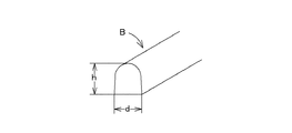
このようにして溶接トーチTにより形成される溶接ビードBを模式的に示した図を、図4に示す。
溶接ビードBの形状は、ビード幅dとビード高さhによって示される。
FIG. 4 schematically shows the weld bead B formed by the welding torch T in this way.
The shape of weld bead B is indicated by bead width d and bead height h.
したがって、溶接ビード形状導出手段12は、入力された溶接条件の印加電圧値・電流値と溶接速度とウィービング量から溶接ビードBのビード幅dとビード高さhの溶接ビード形状データを導出する。
この溶接ビード形状導出手段12により導出された溶接ビード形状データは、溶接パス生成手段14に出力される。
Therefore, the weld bead shape deriving means 12 derives the weld bead shape data of the bead width d and the bead height h of the weld bead B from the applied voltage value / current value, welding speed and weaving amount of the input welding conditions.
The weld bead shape data derived by the weld bead shape deriving means 12 is output to the weld path generating means 14.
一方で、前記差分形状導出手段11により造型前形状データと造型後形状データから導出された差分形状データが、差分形状分割手段13にも入力される。
差分形状データは、造型前形状w1と造型後形状w2の間の差分形状w12を示すもので、対象ワークWの溶接面の形状,対象ワークWの溶接面の傾き等の溶接面の状態および対象ワークWの溶接面上の造型後形状w2の厚み等の各種差分形状データがある。
On the other hand, the differential shape data derived from the pre-molding shape data and the post-molding shape data by the differential
The differential shape data indicates the differential shape w12 between the pre-molding shape w1 and the post-molding shape w2. The shape of the weld surface of the target workpiece W, the state of the weld surface such as the inclination of the weld plane of the target workpiece W, and the target There are various differential shape data such as the thickness of the post-molding shape w2 on the welded surface of the workpiece W.
差分形状分割手段13は、まず差分形状w12を対象ワークWの溶接面の形状や傾き等の状態によって複数の溶接部位に分割するとともに、分割された各溶接部位にそれぞれ対応する造型後形状の厚み等の差分形状データを属性データとして持たせる。 The differential shape dividing means 13 first divides the differential shape w12 into a plurality of weld sites according to the state of the welding surface of the target workpiece W, the inclination, etc., and the thickness of the post-molding shape corresponding to each of the divided weld sites. Etc. are given as attribute data.
例えば、図3に示す対象ワークWの例において、最外周の水平面をなす溶接部位P1,溶接部位P1に連続する鉛直面をなす溶接部位P2,溶接部位P2に連続する水平湾曲面をなす溶接部位P3,溶接部位P3に連続する傾斜面をなす溶接部位P4,溶接部位P4に連続する水平面をなす溶接部位P5,溶接部位P5に連続する鉛直面をなす溶接部位P6,溶接部位P6に連続する最内周の水平面をなす溶接部位P7に分割する。 For example, in the example of the target workpiece W shown in FIG. 3, a welded part P1 forming the outermost horizontal plane, a welded part P2 forming a vertical surface continuous to the welded part P1, and a welded part forming a horizontal curved surface continuous to the welded part P2. P3, a welded part P4 that forms an inclined surface continuous to the welded part P3, a welded part P5 that forms a horizontal plane that continues to the welded part P4, a welded part P6 that forms a vertical surface that continues to the welded part P5, and a welded part P6 that is continuous to the welded part P6 The welding part P7 is divided into the inner peripheral horizontal plane.
そして、分割された各溶接部位P1,P2,P3,P4,P5,P6,P7に、それぞれ対応する溶接面の状態を含む造型後形状の厚み等の差分形状データを属性データとして持たせる。
この差分形状分割手段13により分割された各溶接部位P1,P2,P3,P4,P5,P6,P7のそれぞれの属性データは、溶接パス生成手段14に出力される。
Then, each of the divided welding parts P1, P2, P3, P4, P5, P6, and P7 has differential shape data such as the thickness of the post-molding shape including the state of the corresponding welding surface as attribute data.
The attribute data of each of the welded parts P1, P2, P3, P4, P5, P6, and P7 divided by the differential shape dividing means 13 is output to the welding path generating means 14.
各溶接部位P1,P2,P3,P4,P5,P6,P7のそれぞれの属性データには、互いに近似したものがあり、属性が近似した溶接部位どうしは、溶接経路である溶接パスを同じように設定することができるので、設定をあまり変更することなく連続して溶接造型することが可能で、効率良く造型することができる。
この差分形状分割手段13により分割された各溶接部位P1,P2,P3,P4,P5,P6,P7ごとの属性データは、溶接パス生成手段14に出力される。
The attribute data of each welded part P1, P2, P3, P4, P5, P6, and P7 are similar to each other, and the welded parts that have similar attributes have the same welding path as the welding path. Since it can be set, it is possible to continuously perform the welding molding without changing the setting so much, and the molding can be performed efficiently.
The attribute data for each welding site P1, P2, P3, P4, P5, P6, P7 divided by the differential shape dividing means 13 is output to the welding path generating means 14.
溶接パス生成手段14には、前記差分形状導出手段11から差分形状データ、前記溶接ビード形状導出手段12から溶接ビード形状データ、差分形状分類手段13から溶接部位ごとの属性データがそれぞれ入力されるとともに、オーバーラップ条件が入力される。 The welding path generation means 14 receives the difference shape data from the difference shape derivation means 11, the weld bead shape data from the weld bead shape derivation means 12, and the attribute data for each welded part from the difference shape classification means 13 respectively. The overlap condition is input.
図5に模式的に示すように、溶接ビードBの幅方向に相当する横方向の横方向オーバーラップ量Ldは、先に形成された溶接ビードB1に対して今回横方向にずれて形成される溶接ビードB2が一部重なる部分の横方向の重なり長であり(図5(1)参照)、溶接ビードBの上下方向に相当する縦方向の縦方向オーバーラップ量Lhは、先に形成された溶接ビードB1に対して今回縦方向にずれて形成される溶接ビードB2が一部重なる部分の縦方向の重なり長である(図5(2)参照)。 As shown schematically in FIG. 5, the lateral transverse direction overlap amount Ld corresponding to the width direction of the weld bead B are formed to be shifted in this direction transverse to the weld bead B 1 previously formed that the weld bead B 2 are overlapped length in the horizontal direction of the portion that overlaps a portion (see FIG. 5 (1)), longitudinally overlapping amount Lh in the vertical direction corresponding to the vertical direction of the weld bead B is formed earlier This is the vertical overlap length of the portion where the weld bead B 2 formed by shifting this time in the vertical direction with respect to the weld bead B 1 is partially overlapped (see FIG. 5 (2)).
溶接パス生成手段14に入力されるオーバーラップ条件は、溶接ビードBのビード幅dに対する横方向オーバーラップ量Ldの割合(横方向オーバーラップ割合Ld/d)および溶接ビードBのビード高さhに対する縦方向オーバーラップ量Lhの割合(縦方向オーバーラップ割合Lh/h)で設定される。 The overlap condition input to the welding pass generation means 14 is the ratio of the lateral overlap amount Ld to the bead width d of the weld bead B (lateral overlap ratio Ld / d) and the bead height h of the weld bead B. It is set by the ratio of the vertical overlap amount Lh (vertical overlap ratio Lh / h).
このオーバーラップ条件(横方向オーバーラップ割合Ld/d,縦方向オーバーラップ割合Lh/h)と前記溶接条件(溶接トーチTの印加電圧値・電流値,溶接速度,ウィービング量)は、任意に設定することができる。
したがって、溶接条件から溶接ビード形状導出手段12が導出する溶接ビード形状データ(ビード幅d,ビード高さh)は任意に設定されることになり、この設定された溶接ビード形状(ビード幅d,ビード高さh)にオーバーラップ条件(横方向オーバーラップ割合Ld/d,縦方向オーバーラップ割合Lh/h)を作用(乗算)することで横方向オーバーラップ量Ldと縦方向オーバーラップ量Lhを算出することができる。
The overlap conditions (horizontal overlap ratio Ld / d, vertical overlap ratio Lh / h) and the welding conditions (applied voltage value / current value of welding torch T, welding speed, weaving amount) are arbitrarily set. can do.
Therefore, the weld bead shape data (bead width d, bead height h) derived by the weld bead shape deriving means 12 from the welding conditions is arbitrarily set, and the set weld bead shape (bead width d, bead width d, By applying (multiplying) the overlap condition (horizontal overlap ratio Ld / d, vertical overlap ratio Lh / h) to the bead height h), the horizontal overlap amount Ld and the vertical overlap amount Lh are obtained. Can be calculated.
溶接ビードBを1本の線と仮定した溶接線αを溶接ビードBの中心軸線に設定すると、図5(1)を参照して、ビード幅dと横方向オーバーラップ量Ldから横方向にオーバーラップする溶接ビードB1,B2の溶接線α,α間の横方向間隔は、d−Ldと算出される。
同様に、図5(2)を参照して、ビード高さhと縦方向オーバーラップ量Lhから縦方向にオーバーラップする溶接ビードB1,B2の溶接線α,α間の縦方向間隔は、h−Lhと算出される。
When the weld line α assuming that the weld bead B is a single line is set as the center axis of the weld bead B, referring to FIG. 5 (1), the bead width d and the lateral overlap amount Ld are exceeded in the lateral direction. The lateral interval between the weld lines α and α of the wrapping weld beads B 1 and B 2 is calculated as d−Ld.
Similarly, referring to FIG. 5 (2), the vertical interval between the weld lines α and α of the weld beads B 1 and B 2 that overlap in the vertical direction from the bead height h and the vertical overlap amount Lh is , H−Lh.
溶接パス生成手段14は、溶接ビード形状導出手段12が導出する溶接ビード形状データとオーバーラップ条件を入力して、上記演算によりオーバーラップする溶接ビードB,Bの溶接線α,α間の横方向間隔d−Ldと縦方向間隔h−Lhを算出する。
そして、溶接パス生成手段14には、差分形状導出手段11が造型前形状データと造型後形状データとから導出する差分形状データが入力される。
The welding pass generation means 14 inputs the weld bead shape data derived by the weld bead shape deriving means 12 and the overlap condition, and the transverse direction between the weld lines α and α of the weld beads B and B that overlap by the above calculation. The interval d-Ld and the vertical interval h-Lh are calculated.
Then, the differential shape data derived by the differential
差分形状導出手段11が導出する差分形状データが示す差分形状w12の例を、図6に模式的に2点鎖線で示す。
溶接パス生成手段14は、溶接ビードBにより差分形状w12を肉盛溶接して埋めて造型後形状を造型する溶接トーチTによる溶接経路である溶接パスを生成する。
溶接パスは、溶接トーチTによる溶接経路であり、前記溶接線αが溶接パスの位置を示すことができる。
An example of the difference shape w12 indicated by the difference shape data derived by the difference shape deriving means 11 is schematically shown by a two-dot chain line in FIG.
The welding path generating means 14 generates a welding path that is a welding path by the welding torch T that forms the post-molding shape by overlay welding the differential shape w12 with the weld bead B.
The welding path is a welding path by the welding torch T, and the welding line α can indicate the position of the welding path.
図6を参照して、差分形状w12で示される溶接部位の幅(差分形状データ)と溶接線α,α間の横方向間隔d−Ldから横方向の溶接パスの本数が決定され、溶接部位の高さ(差分形状データ)と溶接線α,α間の縦方向間隔h−Lhから縦方向の溶接パスの本数(層数)が決定される。 Referring to FIG. 6, the number of welding paths in the horizontal direction is determined from the width (difference shape data) of the welded portion indicated by differential shape w12 and the lateral distance d-Ld between weld lines α and α. The number (number of layers) of welding paths in the vertical direction is determined from the height (difference shape data) and the vertical interval h-Lh between the welding lines α and α.
したがって、溶接パス生成手段14は、差分形状w12と溶接ビード形状とに基づいて溶接部位の溶接面に接する端部に最初の溶接パス(溶接線α11)を設定することができ、この1本目の溶接パス(溶接線α11)が設定されると、横方向にオーバーラップして横方向間隔d−Ldだけずれた2本目の溶接パス(溶接線α12)が自動的に生成され、2本目の溶接パス(溶接線α12)の横方向に3本目以降の溶接パス(溶接線α13,α14,…,…)が順次自動的に生成され、決められた本数生成されることで1層目の溶接パスが生成される。 Therefore, the welding path generation means 14 can set the first welding path (welding line α11) at the end portion in contact with the welding surface of the welding portion based on the difference shape w12 and the weld bead shape. When the welding path (welding line α11) is set, a second welding path (welding line α12) that overlaps in the lateral direction and is shifted by the lateral distance d−Ld is automatically generated, and the second welding is performed. The third and subsequent welding passes (welding lines α13, α14,...) Are automatically and sequentially generated in the horizontal direction of the pass (welding line α12), and the first number of welding passes are generated by generating the determined number. Is generated.
次に、1層目の1本目の溶接パス(溶接線α11)の上に縦方向間隔h−Lhだけずれ、差分形状w12と溶接ビード形状とに基づいて2層目の最初の溶接パス(溶接線α21)を設定することができ、この1層目のい1本目の溶接パス(溶接線α11)が設定されると、横方向にオーバーラップして横方向間隔d−Ldだけずれ、縦方向間隔h−Lhだけずれた2本目の溶接パス(溶接線α12)が生成され、以降順次横方向に2層目の溶接パス(溶接線α22,α23,…,…)が生成され、さらに同様にして3層目の溶接パス(溶接線α31,α32,…,…)も生成される。 Next, the first welding pass (welding line α11) of the first layer is shifted by the longitudinal interval h−Lh, and the first welding pass (welding of the second layer) based on the difference shape w12 and the weld bead shape. Line α21) can be set, and when the first welding pass (welding line α11) of the first layer is set, the horizontal direction overlaps and shifts by the horizontal interval d−Ld, and the vertical direction A second welding path (welding line α12) shifted by the interval h−Lh is generated, and then a second layer welding path (welding lines α22, α23,...) Is sequentially generated in the horizontal direction. The third layer welding pass (welding lines α31, α32,...) Is also generated.
以上のように、溶接パス生成手段14は、溶接ビード形状データとオーバーラップ条件からオーバーラップする溶接ビードB,Bの溶接線α,α間の横方向間隔d−Ldと縦方向間隔h−Lhを算出し、この溶接線α,α間の横方向間隔d−Ldと縦方向間隔h−Lhおよび差分形状データと溶接ビード形状データに基づき溶接パスを自動生成することができる。
なお、溶接パス生成手段14は、対象ワークWの溶接部位P1,P2,P3,P4,P5,P6,P7ごとに溶接パスを自動生成する。
As described above, the welding pass generation means 14 is configured to determine the horizontal interval d-Ld and the vertical interval h-Lh between the weld lines α, α of the weld beads B, B that overlap from the weld bead shape data and the overlap condition. , And a welding pass can be automatically generated based on the horizontal interval d-Ld and the vertical interval h-Lh between the weld lines α and α, the difference shape data, and the weld bead shape data.
Note that the welding path generating means 14 automatically generates a welding path for each of the welded parts P1, P2, P3, P4, P5, P6, and P7 of the target workpiece W.
溶接パス生成手段14には、前記差分形状分割手段13により分割された各溶接部位P1,P2,P3,P4,P5,P6,P7ごとの属性データが入力され、溶接パス生成手段14は各溶接部位P1,P2,P3,P4,P5,P6,P7ごとに溶接パスを自動生成する。
そして、溶接パス生成手段14は、属性データから溶接部位P1,P2,P3,P4,P5,P6,P7を、互いに属性が近似する溶接部位どうしを連番として溶接造型する順番を決める。
Attribute data for each welded part P1, P2, P3, P4, P5, P6, P7 divided by the differential shape dividing means 13 is input to the welding path generating means 14, and the welding path generating means 14 A welding pass is automatically generated for each of the parts P1, P2, P3, P4, P5, P6, and P7.
Then, the welding path generating means 14 determines the order in which welding parts P1, P2, P3, P4, P5, P6, and P7 are weld-molded from the attribute data, with the welding parts having similar attributes as serial numbers.
たとえば、溶接部位P1に対して溶接面が水平面で差分形状w12の厚みが略同じ溶接部位P7は近似しており、溶接面が水平面で差分形状w12の厚みが薄い溶接部位P5は次に近似し、溶接面が水平湾曲面をなす溶接部位P3はその次に近似し、溶接面が傾斜面の溶接部位P4はその次に近似し、溶接面が垂直面の溶接部位P2,P6はその次に近似するならば、溶接造型する順番は溶接部位P1,P7,P5,P3,P4,P2,P6の順となる。 For example, a welded part P7 whose welding surface is horizontal and the thickness of the differential shape w12 is approximately the same as the welded part P1 is approximate, and a welding part P5 whose welding surface is horizontal and the differential shape w12 is thin is approximated next. The welding part P3 where the welding surface forms a horizontal curved surface is approximated next, the welding part P4 where the welding surface is an inclined surface is approximated next, and the welding parts P2 and P6 where the welding surface is a vertical surface are next. If approximate, the welding molding order is the order of the welded parts P1, P7, P5, P3, P4, P2, and P6.
属性が近似した溶接部位どうしは、溶接経路である溶接パスを同じように設定することができるので、設定をあまり変更することなく連続して溶接造型することが可能であり、効率良く造型することができる。
このように、溶接パス生成手段14は、対象ワークWの溶接部位の順番を含めた溶接パスを自動生成することができる。
Welding parts with similar attributes can be set in the same way as the welding path that is the welding path, so it is possible to perform continuous welding molding without changing the setting much, and to efficiently mold Can do.
In this way, the welding path generation means 14 can automatically generate a welding path including the order of the welding parts of the target workpiece W.
溶接造型制御装置10には、回転台2と溶接ロボット5を制御する溶接トーチ移動制御手段15を備えており、溶接トーチ移動制御手段15に溶接パス生成手段14が生成した溶接パスデータが入力される。
溶接トーチ移動制御手段15には、溶接条件のうちの溶接速度とウィービング量が別途入力される。
The welding
The welding speed and the weaving amount of the welding conditions are separately input to the welding torch movement control means 15.
溶接トーチ移動制御手段15は、溶接パスデータと溶接速度とウィービング量を入力してデータ処理し、回転台2に溶接速度に基づく回転台制御信号を出力してターンテーブル3に搭載されたタイヤの側部を形成する円環状金型である対象ワークWを回転制御し、溶接ロボット5に溶接パスデータとウィービング量に基づくロボット制御信号を出力して多関節の溶接ロボット5を駆動して溶接トーチTを移動制御する。
The welding torch movement control means 15 inputs the welding pass data, the welding speed and the weaving amount, processes the data, outputs a turntable control signal based on the welding speed to the
また、溶接造型制御装置10には、溶接ロボット5に移動自在に支持される溶接トーチTを制御する溶接トーチ駆動制御手段16を備え、溶接トーチ駆動制御手段16には溶接条件のうちの溶接トーチTの印加電圧値・電流値が入力される。
溶接トーチ駆動制御手段16は、入力された印加電圧値・電流値に従って溶接トーチTに電圧・電流を加えて溶接トーチTを駆動制御する。
Further, the welding
The welding torch drive control means 16 drives and controls the welding torch T by applying a voltage / current to the welding torch T according to the input applied voltage value / current value.
溶接造型制御装置10の溶接トーチ移動制御手段15と溶接トーチ駆動制御手段16は、協働して回転台2,溶接ロボット5,溶接トーチTを制御して、自動生成された溶接パスに従って対象ワークWの所要箇所を順次溶接造型していく。
The welding torch movement control means 15 and the welding torch drive control means 16 of the welding
図3に断面形状を示す円環状金型である対象ワークWについて、前記したように定めた溶接造型する順番(溶接部位P1,P7,P5,P3,P4,P2,P6)に従って造型する場合は、まず最外周の溶接部位P1から同溶接部位P1について生成した溶接パスに従って溶接造型を開始する。 When the target workpiece W, which is an annular mold having a cross-sectional shape shown in FIG. 3, is formed according to the welding molding order (welding sites P1, P7, P5, P3, P4, P2, P6) determined as described above. First, welding molding is started according to the welding path generated for the welded part P1 from the outermost welded part P1.
すなわち、溶接ロボット5を駆動して溶接部位P1の1本目の溶接パスの開始位置に溶接トーチTを位置決めし、溶接トーチTを駆動すると同時に回転台2を駆動して対象ワークWを回転制御し、同時に溶接ロボット5により溶接トーチTを振動させることで、ウィービングによる溶接ビードBが1本目の溶接パス(溶接線α)に沿って肉盛溶接されて形成される。
That is, the
対象ワークWが1周すると、2本目の溶接パス(溶接線α)に沿って同様にして溶接ビードBが肉盛溶接され、以後溶接部位P1について決められた本数の溶接パスに沿って順次肉盛溶接がなされ、溶接部位P1の造型後形状が造型される。
次に、溶接ロボット5を駆動して溶接部位P7の1本目の溶接パスの開始位置に溶接トーチTを移動し、溶接ビードBの肉盛溶接を開始し、溶接部位P1のときと同様にして溶接部位P2の造型後形状が造型される。
When the target workpiece W makes one turn, the weld bead B is welded in the same manner along the second welding pass (welding line α), and thereafter the meat is sequentially welded along the number of welding passes determined for the welding portion P1. Saddle welding is performed, and the post-molding shape of the welded part P1 is molded.
Next, the
溶接部位P1と溶接部位P7は、属性データに互いに近似しており、溶接経路である溶接パスを同じように設定することができるので、設定をあまり変更することなく連続して溶接造型することが可能で、効率良く造型することができる。
このようにして、残りの溶接部位P5,P3,P4,P2,P6について、この順番に溶接造型がなされ、対象ワークW全体の造型後形状が造型される。
The welded part P1 and the welded part P7 are similar to each other in the attribute data, and the welding path that is the welding path can be set in the same way, so that it is possible to continuously perform welding molding without changing the setting much. It is possible and can be molded efficiently.
In this way, the remaining welded parts P5, P3, P4, P2, and P6 are welded in this order, and the post-molding shape of the entire target workpiece W is molded.
一方で、円環状金型のように円環状をした対象ワークに周方向に肉盛溶接する場合、外径側から内径側に肉盛溶接して造型する方が、歪みが抑えられることが分かっているので、溶接部位の切換えごとの設定の変更を厭わなければ、溶接部位P1,P2,P3,P4,P5,P6,P7の順に肉盛溶接して造型する方がよい。
周方向に肉盛溶接するものでない場合は、前記したように属性の近い順番に造型していくのが効率的である。
On the other hand, it is found that when overlay welding is performed in a circumferential direction on an annular workpiece such as an annular mold, distortion is suppressed by overlay welding from the outer diameter side to the inner diameter side. Therefore, if it is not necessary to change the setting every time the welding part is switched, it is better to form by welding in the order of the welding parts P1, P2, P3, P4, P5, P6 and P7.
In the case where welding is not performed in the circumferential direction, it is efficient to mold in the order of close attributes as described above.
なお、1本の溶接パスは、本対象ワークWの1周全てに生成されるとは限らず、よって、対象ワークWの回転に伴って溶接トーチTにより溶接ビードBが肉盛形成されるが、溶接トーチTの駆動を所定タイミングで停止して所要箇所のみ部分的に溶接ビードBを形成する場合もある。 Note that one weld pass is not necessarily generated on the entire circumference of the target workpiece W. Therefore, the weld bead B is overlaid by the welding torch T as the target workpiece W rotates. In some cases, the driving of the welding torch T is stopped at a predetermined timing, and the weld bead B is partially formed only at a required portion.
また、溶接造型により形成される対象ワークWの造型後形状は、当初造型後形状データとして入力された造型後形状と略等しいが細部まで一致するものではなく、ただし造型後形状データの造型後形状を包含する。
溶接造型された対象ワークWは、仕上げ加工が施されて所要形状のタイヤ用金型として再生される。
In addition, the post-molding shape of the target workpiece W formed by welding molding is approximately the same as the post-molding shape input as the initial post-molding shape data, but does not match the details, but the post-molding shape of the post-molding shape data Is included.
The target workpiece W that has been welded is subjected to finish processing and regenerated as a tire mold having a required shape.
以上のように、溶接造型装置1の溶接造型制御装置10は、造型前形状データと造型後形状データから導出される差分形状データ,溶接条件から導出される溶接ビード形状データおよびオーバーラップ条件に基づき、溶接ビードBにより肉盛溶接して差分形状を埋めて造型後形状を造型する溶接トーチTの溶接パスを自動生成するので、工数を大幅に削減し、労力と時間を軽減することができる。
As described above, the welding
溶接条件は任意に入力して、溶接ビード形状を任意に設定することができるが、ウィービング量は、7mm以下とするのが適切である。
ウィービング量が7mmを越えると、蛇行する溶接ビードBの凹部が深くなり過ぎ、エアが溜り溶接欠陥が生じ易いが、ウィービング量を7mm以下とすることで、溶接欠陥を少なくすることができる。
Although welding conditions can be arbitrarily input and the weld bead shape can be arbitrarily set, the weaving amount is suitably 7 mm or less.
If the weaving amount exceeds 7 mm, the concave portion of the meandering weld bead B becomes too deep and air is easily accumulated, so that welding defects are likely to occur. However, if the weaving amount is 7 mm or less, the welding defects can be reduced.
また、オーバーラップ条件も任意に設定可能であるが、横方向オーバーラップ割合は10〜40%が適切である。
横方向オーバーラップ割合が10%未満であると、オーバーラップする溶接ビードB,B間にエアが形成されるおそれがあり、また横方向オーバーラップ割合が40%を越えると、重なる量が大きく溶接ビードの肉盛形状を制御することが難しくなるとともに、溶接欠陥も生じ易くなる。
In addition, the overlap condition can be arbitrarily set, but a suitable overlap ratio in the horizontal direction is 10 to 40%.
If the overlap ratio in the horizontal direction is less than 10%, air may be formed between the overlapping weld beads B and B. If the overlap ratio in the horizontal direction exceeds 40%, the amount of overlap will be large. It becomes difficult to control the build-up shape of the bead, and welding defects are likely to occur.
本実施の形態では、タイヤ用金型を対象ワークとしたが、タイヤ用金型以外に種々のものを対象ワークとして適用することができる。 In the present embodiment, the tire mold is the target work, but various things other than the tire mold can be applied as the target work.
W…対象ワーク、w1…造型前形状、w2…造型後形状、w12…差分形状、P1,P2,P3,P4,P5,P6,P7…溶接部位、T…溶接トーチ、B…溶接ビード、α…溶接線、
1…溶接造型装置、2…回転台、3…ターンテーブル、5…溶接ロボット、
10…溶接造型制御装置、11…差分形状導出手段、12…溶接ビード形状導出手段、13…差分形状分割手段、14…溶接パス生成手段、15…溶接トーチ移動制御手段、16…溶接トーチ駆動制御手段。
W: target workpiece, w1: pre-molding shape, w2: post-molding shape, w12: differential shape, P1, P2, P3, P4, P5, P6, P7 ... welding site, T ... welding torch, B ... welding bead, α ... welding lines,
DESCRIPTION OF
DESCRIPTION OF
Claims (8)
溶接トーチの印加電圧値・電流値と溶接速度とウィービング量の溶接条件を任意に設定し、
前記溶接条件の下で前記溶接トーチにより溶接線に沿って形成される溶接ビードの溶接ビード形状の溶接ビード形状データを前記溶接条件から導出し、
前記溶接ビードのオーバーラップ条件を任意に設定し、
前記溶接条件の下で形成される前記溶接ビードにより肉盛溶接して前記差分形状を埋めて前記造型後形状を造型する前記溶接トーチの溶接パスを、前記溶接ビード形状データと前記差分形状データと前記オーバーラップ条件に基づき自動生成することを特徴とする溶接造型制御方法。 The difference shape data of the difference shape between the pre-molding shape and the post-molding shape of the target workpiece is derived from the pre-molding shape data and the post-molding shape data,
Set the welding voltage of the welding torch arbitrarily, including the applied voltage value / current value, welding speed, and weaving amount.
Deriving weld bead shape data of a weld bead shape of a weld bead formed along a weld line by the welding torch under the welding conditions from the welding conditions;
Set the welding bead overlap condition arbitrarily,
Welding pass of the welding torch for overlay welding with the weld bead formed under the welding conditions to fill the differential shape and forming the post-molding shape, the weld bead shape data and the differential shape data A welding molding control method, which is automatically generated based on the overlap condition.
前記差分形状を前記対象ワークの溶接面の状態に基づいて複数の溶接部位に分割し、
分割された各溶接部位にそれぞれ対応する前記造型後形状の厚み等の差分形状データを属性データとして持たせ、
各溶接部位ごとの属性データに基づいて各溶接部位の溶接順序を決定して前記溶接トーチの溶接パスを自動生成することを特徴とする請求項2記載の溶接造型制御方法。 The differential shape data includes various differential shape data such as the shape of the weld surface of the target workpiece and the state of the weld surface such as the inclination and the thickness of the post-molding shape on the weld surface of the target workpiece,
Dividing the difference shape into a plurality of welding sites based on the state of the welding surface of the target workpiece,
Having as an attribute data differential shape data such as the thickness of the post-molding shape corresponding to each of the divided weld sites,
The welding shaping control method according to claim 2, wherein a welding order of each welding part is determined based on attribute data for each welding part, and a welding path of the welding torch is automatically generated.
対象ワークの造型前形状データと造型後形状データに基づき対象ワークの造型前形状と造型後形状の差分形状の差分形状データを導出する差分形状導出手段と、
前記溶接トーチの印加電圧値・電流値と溶接速度とウィービング量の溶接条件に基づき前記溶接トーチにより溶接線に沿って形成される溶接ビードの溶接ビード形状の溶接ビード形状データを導出する溶接ビード形状導出手段と、
前記差分形状導出手段が導出した前記差分形状データと前記溶接ビード形状導出手段が導出した前記溶接ビード形状データとオーバーラップ条件に基づいて前記溶接条件の下で形成される前記溶接ビードにより肉盛溶接して前記差分形状を埋めて前記造型後形状を造型する前記溶接トーチの溶接パスを生成する溶接パス生成手段と、
前記溶接パス生成手段が生成した溶接パスと前記溶接条件に従って前記溶接トーチを移動制御する溶接トーチ移動制御手段と、
前記溶接条件に従って前記溶接トーチを駆動制御する溶接トーチ駆動制御手段とを備えたことを特徴とする溶接造型制御装置。 In a welding molding control device for controlling the movement of a welding torch and overlay welding to a target workpiece with a welding bead,
Differential shape deriving means for deriving differential shape data of the differential shape between the pre-molding shape and the post-molding shape of the target workpiece based on the pre-molding shape data and the post-molding shape data of the target workpiece;
A weld bead shape for deriving weld bead shape data of a weld bead shape of the weld bead formed along the weld line by the welding torch based on the welding voltage of the welding torch, the applied voltage value, the current value, the welding speed, and the weaving amount. Deriving means;
Overlay welding with the weld bead formed under the welding condition based on the difference shape data derived by the difference shape deriving means, the weld bead shape data derived by the weld bead shape deriving means, and an overlap condition A welding path generating means for generating a welding path of the welding torch that fills the differential shape and forms the post-molding shape;
Welding torch movement control means for controlling movement of the welding torch according to the welding path generated by the welding path generation means and the welding conditions;
A welding molding control device comprising welding torch drive control means for driving and controlling the welding torch according to the welding conditions.
前記差分形状を前記対象ワークの溶接面の状態に基づいて複数の溶接部位に分割するとともに、分割された各溶接部位にそれぞれ対応する前記造型後形状の厚み等の差分形状データを属性データとして持たせる差分形状分割手段を備え、
前記溶接パス生成手段は、前記各溶接部位ごとの属性データに基づいて各溶接部位の溶接順序を決定して前記溶接トーチの溶接パスを自動生成することを特徴とする請求項7記載の溶接造型制御装置。 The differential shape data derived by the differential shape deriving means includes various differential shapes such as the shape of the weld surface of the target workpiece and the state of the weld surface such as the inclination and the thickness of the post-molding shape on the weld surface of the target workpiece. There is data
The differential shape is divided into a plurality of weld sites based on the state of the weld surface of the target workpiece, and has differential shape data such as the thickness of the post-molding shape corresponding to each of the divided weld sites as attribute data. Differential shape dividing means for
8. The welding molding according to claim 7, wherein the welding path generating means automatically generates a welding path of the welding torch by determining a welding order of each welding site based on attribute data for each welding site. Control device.
Priority Applications (1)
| Application Number | Priority Date | Filing Date | Title |
|---|---|---|---|
| JP2015076126A JP2016196012A (en) | 2015-04-02 | 2015-04-02 | Weld molding control method and weld molding control apparatus |
Applications Claiming Priority (1)
| Application Number | Priority Date | Filing Date | Title |
|---|---|---|---|
| JP2015076126A JP2016196012A (en) | 2015-04-02 | 2015-04-02 | Weld molding control method and weld molding control apparatus |
Publications (1)
| Publication Number | Publication Date |
|---|---|
| JP2016196012A true JP2016196012A (en) | 2016-11-24 |
Family
ID=57357122
Family Applications (1)
| Application Number | Title | Priority Date | Filing Date |
|---|---|---|---|
| JP2015076126A Pending JP2016196012A (en) | 2015-04-02 | 2015-04-02 | Weld molding control method and weld molding control apparatus |
Country Status (1)
| Country | Link |
|---|---|
| JP (1) | JP2016196012A (en) |
Cited By (10)
| Publication number | Priority date | Publication date | Assignee | Title |
|---|---|---|---|---|
| JP2017144458A (en) * | 2016-02-16 | 2017-08-24 | 株式会社神戸製鋼所 | Lamination control device, lamination control method and program |
| WO2018198871A1 (en) * | 2017-04-27 | 2018-11-01 | 株式会社神戸製鋼所 | Joining method and structure for laminate shaping component, and laminate shaping component |
| JP2018183815A (en) * | 2017-04-27 | 2018-11-22 | 株式会社神戸製鋼所 | Bonding method of laminated shaped part, structure, and laminated shaped part |
| JP2019089126A (en) * | 2017-11-15 | 2019-06-13 | 株式会社神戸製鋼所 | Manufacturing method of molded body, manufacturing apparatus, and molded body |
| JP2019136711A (en) * | 2018-02-06 | 2019-08-22 | 株式会社神戸製鋼所 | Manufacturing method of laminated molding |
| EP3581312A4 (en) * | 2017-02-08 | 2020-12-16 | Kabushiki Kaisha Kobe Seiko Sho (Kobe Steel, Ltd.) | Lamination control device, and lamination control method and program |
| JP2021000644A (en) * | 2019-06-20 | 2021-01-07 | 株式会社神戸製鋼所 | Production method for molding material, production control method for molding material, production control device for molding material and program |
| US11292071B2 (en) | 2017-11-15 | 2022-04-05 | Kobe Steel, Ltd. | Method for producing molded article, production device, and molded article |
| US11325190B2 (en) | 2018-10-18 | 2022-05-10 | Mitsubishi Electric Corporation | Additive manufacturing method and machining-path generation method |
| US11480947B2 (en) | 2019-06-14 | 2022-10-25 | Mitsubishi Electric Corporation | Control information generation device and control information generation method for controlling an additive manufacturing apparatus using bead width correction |
-
2015
- 2015-04-02 JP JP2015076126A patent/JP2016196012A/en active Pending
Cited By (17)
| Publication number | Priority date | Publication date | Assignee | Title |
|---|---|---|---|---|
| JP2017144458A (en) * | 2016-02-16 | 2017-08-24 | 株式会社神戸製鋼所 | Lamination control device, lamination control method and program |
| US10994370B2 (en) | 2017-02-08 | 2021-05-04 | Kobe Steel, Ltd. | Lamination control device, and lamination control method and program |
| EP3581312A4 (en) * | 2017-02-08 | 2020-12-16 | Kabushiki Kaisha Kobe Seiko Sho (Kobe Steel, Ltd.) | Lamination control device, and lamination control method and program |
| WO2018198871A1 (en) * | 2017-04-27 | 2018-11-01 | 株式会社神戸製鋼所 | Joining method and structure for laminate shaping component, and laminate shaping component |
| JP2018183815A (en) * | 2017-04-27 | 2018-11-22 | 株式会社神戸製鋼所 | Bonding method of laminated shaped part, structure, and laminated shaped part |
| US11654500B2 (en) | 2017-04-27 | 2023-05-23 | Kobe Steel, Ltd. | Joining method and structure for laminate shaping component, and laminate shaping component |
| CN110603115A (en) * | 2017-04-27 | 2019-12-20 | 株式会社神户制钢所 | Method for joining laminated molded parts, structure, and laminated molded part |
| CN110603115B (en) * | 2017-04-27 | 2021-08-10 | 株式会社神户制钢所 | Method for joining laminated molded parts, structure, and laminated molded part |
| US11292071B2 (en) | 2017-11-15 | 2022-04-05 | Kobe Steel, Ltd. | Method for producing molded article, production device, and molded article |
| EP3711889A4 (en) * | 2017-11-15 | 2021-09-01 | Kabushiki Kaisha Kobe Seiko Sho (Kobe Steel, Ltd.) | Method for producing molded article, production device, and molded article |
| JP7028737B2 (en) | 2017-11-15 | 2022-03-02 | 株式会社神戸製鋼所 | Manufacturing method of modeled object, manufacturing equipment and modeled object |
| JP2019089126A (en) * | 2017-11-15 | 2019-06-13 | 株式会社神戸製鋼所 | Manufacturing method of molded body, manufacturing apparatus, and molded body |
| JP2019136711A (en) * | 2018-02-06 | 2019-08-22 | 株式会社神戸製鋼所 | Manufacturing method of laminated molding |
| US11325190B2 (en) | 2018-10-18 | 2022-05-10 | Mitsubishi Electric Corporation | Additive manufacturing method and machining-path generation method |
| US11480947B2 (en) | 2019-06-14 | 2022-10-25 | Mitsubishi Electric Corporation | Control information generation device and control information generation method for controlling an additive manufacturing apparatus using bead width correction |
| JP2021000644A (en) * | 2019-06-20 | 2021-01-07 | 株式会社神戸製鋼所 | Production method for molding material, production control method for molding material, production control device for molding material and program |
| JP7223644B2 (en) | 2019-06-20 | 2023-02-16 | 株式会社神戸製鋼所 | Modeled article manufacturing method and modeled article manufacturing control method |
Similar Documents
| Publication | Publication Date | Title |
|---|---|---|
| JP2016196012A (en) | Weld molding control method and weld molding control apparatus | |
| US11759879B2 (en) | Synchronized rotating arc welding method and system | |
| CN102218578B (en) | Path planning method for complicated-shape workpiece of robot bead weld based on radial bias | |
| US11772194B2 (en) | Method for designing laminate molded article, production method, production device, and program | |
| JP6892371B2 (en) | Manufacturing method and manufacturing equipment for laminated models | |
| JP6797244B1 (en) | Laminated modeling method | |
| JP7120774B2 (en) | Laminate-molded article modeling procedure design method, laminate-molded article modeling method, manufacturing apparatus, and program | |
| US11415962B2 (en) | Additively-manufactured object by forming beads along a formation projected line of beads | |
| Ugla et al. | Deposition-path generation of SS308 components manufactured by TIG welding-based shaped metal deposition process | |
| KR102008949B1 (en) | welder of exclusive use of ship block | |
| JP6765360B2 (en) | Structure manufacturing method and structure | |
| JP7123738B2 (en) | LAMINATED PRODUCT MANUFACTURING METHOD AND LAMINATED MOLDED PRODUCT | |
| JP2019089126A (en) | Manufacturing method of molded body, manufacturing apparatus, and molded body | |
| JP4058099B2 (en) | Two-electrode arc welding end method | |
| JP7193423B2 (en) | Laminate-molded article manufacturing method | |
| JP2019063858A (en) | Method for manufacturing laminated molding and laminated molding | |
| JP6964530B2 (en) | Pipe joining structure and joining method | |
| JP2014155959A (en) | Method and apparatus for producing mold material | |
| WO2019181556A1 (en) | Method for producing shaped article and shaped article | |
| WO2019098021A1 (en) | Method for producing molded article, production device, and molded article | |
| JP2020082287A (en) | Welding robot | |
| JP7381422B2 (en) | Manufacturing method of modeled object and modeled object | |
| JP7355672B2 (en) | Manufacturing method for additively manufactured objects | |
| JP7355701B2 (en) | Additive manufacturing method | |
| JP2004330227A (en) | Bead patching method for circumferential multilayer welding, and automatic welding equipment |