JP2016188591A - Centrifugal pump device - Google Patents
Centrifugal pump device Download PDFInfo
- Publication number
- JP2016188591A JP2016188591A JP2015068560A JP2015068560A JP2016188591A JP 2016188591 A JP2016188591 A JP 2016188591A JP 2015068560 A JP2015068560 A JP 2015068560A JP 2015068560 A JP2015068560 A JP 2015068560A JP 2016188591 A JP2016188591 A JP 2016188591A
- Authority
- JP
- Japan
- Prior art keywords
- impeller
- dynamic pressure
- partition wall
- peripheral surface
- permanent magnets
- Prior art date
- Legal status (The legal status is an assumption and is not a legal conclusion. Google has not performed a legal analysis and makes no representation as to the accuracy of the status listed.)
- Pending
Links
Images


Landscapes
- External Artificial Organs (AREA)
- Connection Of Motors, Electrical Generators, Mechanical Devices, And The Like (AREA)
- Permanent Magnet Type Synchronous Machine (AREA)
- Structures Of Non-Positive Displacement Pumps (AREA)
Abstract
Description
この発明は遠心式ポンプ装置に関し、特に、回転時の遠心力によって液体を送るインペラを備えた遠心式ポンプ装置に関する。 The present invention relates to a centrifugal pump device, and more particularly to a centrifugal pump device provided with an impeller that sends liquid by a centrifugal force during rotation.
近年、隔壁によってモータ駆動室とロータ室とに分離した構造のキャンドモータが多く用いられている。このようなモータは、たとえば、粉塵をきらう環境下で使用される半導体製造ラインの純水輸送用ポンプや、生体液を輸送するポンプに使用されている。 In recent years, a canned motor having a structure in which a motor drive chamber and a rotor chamber are separated by a partition wall is often used. Such a motor is used, for example, in a pump for transporting pure water in a semiconductor production line used in an environment where dust is not desired or a pump for transporting biological fluid.
特開2010−261394号公報(特許文献1)には、流体動圧軸受によるインペラの非接触浮上と、キャンドモータ構造を特徴とするアキシアルギャップ型の遠心式ポンプが記載されている。流体動圧軸受によるインペラの非接触浮上を特徴とするアキシアルギャップ型の遠心式ポンプでは、インペラとモータとの間に働くアキシアル方向吸引力を相殺するように、インペラを挟んだ反対側でリング状永久磁石等によりアキシアル方向の吸引力バランスをとっている。 Japanese Patent Laid-Open No. 2010-261394 (Patent Document 1) describes an axial gap type centrifugal pump characterized by non-contact floating of an impeller by a fluid dynamic pressure bearing and a canned motor structure. In an axial gap type centrifugal pump characterized by non-contact floating of the impeller by the hydrodynamic bearing, a ring shape is formed on the opposite side of the impeller so as to cancel the axial suction force acting between the impeller and the motor. Balance of attractive force in the axial direction by permanent magnets.
しかし、これらの永久磁石等による吸引力は、インペラが一方向へ近づくとよりその方向へ近づこうとする負剛性(不安定要素)の成分である。また、例えば流量が多い場合では、流体出口の位置の影響で周方向に圧力差が生じ、インペラがモータの回転中心からラジアル方向へ偏心してしまう。このため、この遠心式ポンプは、駆動モータ側のアキシアル方向吸引力や、それを相殺するためのリング磁石側のアキシアル方向吸引力の相互バランスにより、外乱や流体力によってインペラが定常浮上位置からずれてしまう場合がある。 However, the attractive force by these permanent magnets or the like is a component of negative rigidity (unstable element) that tends to approach the impeller more in one direction. Further, for example, when the flow rate is large, a pressure difference is generated in the circumferential direction due to the influence of the position of the fluid outlet, and the impeller is eccentric from the rotation center of the motor in the radial direction. For this reason, this centrifugal pump has an impeller that deviates from the normal levitation position due to disturbance and fluid force due to the mutual balance of the axial suction force on the drive motor side and the axial suction force on the ring magnet side to offset it. May end up.
このように、インペラの偏心により変化したアキシアル吸引力を制御する方法として、特開2010−261394号公報(特許文献1)では、モータ側吸引力がリング状磁石部の吸引力変化と釣合うように、モータ電流位相を調整することで対応していた。これにより、外乱や動作条件によりインペラがラジアル方向へ偏心しても、インペラのアキシアル方向の浮上位置を変化させずに安定回転を維持することが可能であった。 As described above, as a method of controlling the axial attractive force changed due to the eccentricity of the impeller, in Japanese Patent Application Laid-Open No. 2010-261394 (Patent Document 1), the motor-side attractive force is balanced with the attractive force change of the ring-shaped magnet portion. In addition, the motor current phase was adjusted. As a result, even if the impeller is eccentric in the radial direction due to disturbances or operating conditions, stable rotation can be maintained without changing the floating position of the impeller in the axial direction.
上述のように、特開2010−261394号公報に記載されたような遠心式ポンプでは、外乱や動作条件によりインペラがラジアル方向へ偏心しても、インペラのアキシアル方向の浮上位置を変化させずに安定回転を維持するために、モータ側吸引力がリング状永久磁石部の吸引力変化と釣合うようにモータ電流位相を調整する等の対策が行なわれている。 As described above, in the centrifugal pump as described in Japanese Patent Application Laid-Open No. 2010-261394, even if the impeller is eccentric in the radial direction due to disturbances or operating conditions, it is stable without changing the floating position of the impeller in the axial direction. In order to maintain the rotation, measures are taken such as adjusting the motor current phase so that the motor-side attractive force balances the change in the attractive force of the ring-shaped permanent magnet portion.
しかしモータ電流位相を変化させるということは、種々の問題が生じるおそれがある。例えばモータを最大効率点で動作させていた状況から電流位相が変化してしまうと、モータ効率の低下を招く可能性がある。また例えば、最大トルク点で動作させていた状況から電流位相を変化させると、発生トルクが低下しポンプ出力の低下やモータの脱調の可能性があった。 However, changing the motor current phase may cause various problems. For example, if the current phase changes from the situation where the motor is operated at the maximum efficiency point, the motor efficiency may be reduced. Further, for example, when the current phase is changed from the situation where the operation is performed at the maximum torque point, the generated torque is reduced, and there is a possibility that the pump output is reduced or the motor is stepped out.
クリーン状態が必須であるポンプ用途では、インペラとポンプ室の内壁との接触等による汚染物質の発生、およびその混入は確実に防ぐ必要がある。その一方で、モータの効率低下やポンプ出力低下はできる限り避けることが望ましい。 In pump applications where a clean state is essential, it is necessary to reliably prevent the generation of contaminants and their contamination due to contact between the impeller and the inner wall of the pump chamber. On the other hand, it is desirable to avoid motor efficiency reduction and pump output reduction as much as possible.
この発明は、上記の課題を解決するためになされたものであって、その目的は、汚染防止と効率や性能の低下の防止とを両立することができる遠心式ポンプ装置を提供することである。 The present invention has been made to solve the above-described problems, and an object thereof is to provide a centrifugal pump device capable of achieving both prevention of contamination and prevention of reduction in efficiency and performance. .
この発明は、要約すると、遠心式ポンプ装置であって、ハウジングと、インペラと、駆動部と、複数の第1の永久磁石とを備える。 In summary, the present invention is a centrifugal pump device that includes a housing, an impeller, a drive unit, and a plurality of first permanent magnets.
ハウジングは、隔壁で仕切られた第1および第2の室を含む。インペラは、第1の室内において隔壁に交差する軸を回転軸として回転可能に設けられ、回転時の遠心力によって液体を送る。駆動部は、第2の室内に設けられ、隔壁を介してインペラを回転駆動させる。複数の第1の永久磁石は、隔壁に沿うインペラの一方面に設けられ、同一の円に沿って配置される。 The housing includes first and second chambers separated by a partition wall. The impeller is rotatably provided with an axis that intersects the partition wall as a rotation axis in the first chamber, and sends liquid by centrifugal force during rotation. The drive unit is provided in the second chamber and rotationally drives the impeller through the partition wall. The plurality of first permanent magnets are provided on one surface of the impeller along the partition and are disposed along the same circle.
駆動部は、複数の第1の永久磁石に対向して設けられ、回転磁界を生成するための複数の空芯コイルを含む。インペラの一方面と反対側の他方面またはそれに対向する第1の室の内壁に第1の動圧溝が形成され、インペラの一方面またはそれに対向する隔壁に第2の動圧溝が形成され、インペラの外周面もしくはそれに対向する第1の室の内周面、またはインペラの内周面もしくはそれに対向する第1の室の外周面に第3の動圧溝が形成されている。 The drive unit includes a plurality of air-core coils that are provided to face the plurality of first permanent magnets and generate a rotating magnetic field. A first dynamic pressure groove is formed on the other surface of the impeller opposite to the other surface or on the inner wall of the first chamber facing the first surface, and a second dynamic pressure groove is formed on the one surface of the impeller or the partition wall facing it. A third dynamic pressure groove is formed on the outer peripheral surface of the impeller or the inner peripheral surface of the first chamber facing the impeller, or on the inner peripheral surface of the impeller or the outer peripheral surface of the first chamber facing the impeller.
上記に示したように、駆動部のコイルはコアレス構造とすることでアキシアル吸引力が働かない構成とし、そのため駆動部側吸引力を相殺するためのリング状永久磁石も配置せず、インペラに作用する負剛性成分を排除している。また、従来の構造ではリング磁石によりインペラのラジアル方向復元力を確保していたが、本装置の場合はインペラの内外周面、或いはそれに対向する第1の室内壁面に新たなラジアル動圧溝を追加することで、ラジアル方向を支持した構造としている。 As shown above, the coil of the drive unit has a coreless structure so that the axial attractive force does not work, so there is no ring-shaped permanent magnet to cancel the drive unit side attractive force, and it acts on the impeller The negative stiffness component is eliminated. Further, in the conventional structure, the radial restoring force of the impeller is secured by the ring magnet, but in the case of this apparatus, a new radial dynamic pressure groove is provided on the inner and outer peripheral surfaces of the impeller or the first indoor wall surface facing the impeller. By adding, it has a structure that supports the radial direction.
好ましくは、駆動部は、複数の空芯コイルの隔壁と反対側に配置され、複数の空芯コイルと磁気的に結合される磁性体をさらに含む。 Preferably, the drive unit further includes a magnetic body that is disposed on the side opposite to the partition walls of the plurality of air-core coils and is magnetically coupled to the plurality of air-core coils.
好ましくは、複数の第1の永久磁石は、隣接する磁極が互いに異なるように同一の円に沿って配置される。 Preferably, the plurality of first permanent magnets are arranged along the same circle such that adjacent magnetic poles are different from each other.
従来の構成では、駆動モータ側の吸引力や、それを相殺するためのリング磁石側の吸引力のアキシアル方向の負剛性成分が、インペラ挙動の不安定の原因となっていたが、本発明では駆動部のコイルを空芯コイルとすることによってアキシアル方向に働く吸引力を排除した構成とし、インペラの浮上回転時の安定性を高めることができる。 In the conventional configuration, the attractive force on the drive motor side and the negative stiffness component in the axial direction of the attractive force on the ring magnet side to cancel it cause instability of the impeller behavior. By using an air-core coil as the coil of the drive unit, it is possible to eliminate the attractive force acting in the axial direction, and to improve the stability of the impeller during the floating rotation.
以下、本発明の実施の形態について、図面を参照しながら詳細に説明する。なお、図中同一または相当部分には同一符号を付してその説明は繰返さない。 Hereinafter, embodiments of the present invention will be described in detail with reference to the drawings. In the drawings, the same or corresponding parts are denoted by the same reference numerals and description thereof will not be repeated.
[ポンプ部の基本構成の説明]
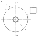
図1は、本発明の実施の形態の遠心式ポンプ装置のポンプ部1の外観を示す正面図である。図2は、図1に示したポンプ部1の側面図である。図3は、図2のIII−III線断面図である。図4は、図3のIV−IV線断面図である。
[Description of basic configuration of pump unit]
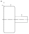
FIG. 1 is a front view showing an appearance of a
図1〜図4を参照して、この遠心式ポンプ装置のポンプ部1は、非磁性材料で形成されたハウジング2を備える。ハウジング2は、円柱状の本体部3と、本体部3の一方の端面の中央に立設された円筒状の流入ポート4と、本体部3の外周面に設けられた円筒状の流出ポート5とを含む。流出ポート5は、本体部3の外周面の接線方向に延在している。
With reference to FIGS. 1-4, the
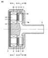
ハウジング2内には、図3に示すように、隔壁6によって仕切られたポンプ室7およびモータ室8が設けられている。ポンプ室7内には、図3および図4に示すように、中央に貫通孔10aを有する円板状のインペラ10が回転可能に設けられている。インペラ10は、ドーナツ板状の2枚のシュラウド11,12と、2枚のシュラウド11,12間に形成された複数(たとえば6つ)のベーン13とを含む。シュラウド11は流入ポート4側に配置され、シュラウド12は隔壁6側に配置される。シュラウド11,12およびベーン13は、非磁性材料で形成されている。
As shown in FIG. 3, a
2枚のシュラウド11,12の間には、複数のベーン13で仕切られた複数(この場合は6つ)の通路14が形成されている。通路14は、図4に示すように、インペラ10の中央の貫通孔10aと連通しており、インペラ10の貫通孔10aを始端とし、外周縁まで徐々に幅が広がるように延びている。換言すれば、隣接する2つの通路14間にベーン13が形成されている。なお、本実施の形態では、複数のベーン13は等角度間隔で設けられ、かつ同じ形状に形成されている。したがって、複数の通路14は等角度間隔で設けられ、かつ同じ形状に形成されている。
Between the two
インペラ10が回転駆動されると、流入ポート4から流入した液体は、遠心力によって貫通孔10aから通路14を介してインペラ10の外周部に送られ、流出ポート5から流出する。
When the
[永久磁石の配置の説明]
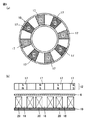
図5は、インペラ10のシュラウドに埋設された磁石の詳細な配置を示す図である。図4および図5を参照して、シュラウド12には複数(たとえば8個)の永久磁石17が埋設されている。複数の永久磁石17は、隣接する磁極が互いに異なるようにして、等角度間隔で同一の円に沿って隙間を設けて配置される。換言すれば、モータ室8側にN極を向けた永久磁石17と、モータ室8側にS極を向けた永久磁石17とが等角度間隔で隙間を設けて同一の円に沿って交互に配置されている。
[Description of permanent magnet arrangement]
FIG. 5 is a diagram showing a detailed arrangement of the magnets embedded in the shroud of the
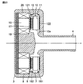
図6は、図3のVI−VI線断面図である。図3および図6を参照して、モータ室8内には、複数(たとえば9個)の空芯コイル20が設けられている。複数の空芯コイル20は、インペラ10の複数の永久磁石17に隔壁を挟み対向して、等角度間隔で同一の円に沿って配置される。空芯コイル20は、磁性体などが配置されていない空芯部18の周りにコイル配線が巻回されている。
6 is a cross-sectional view taken along line VI-VI in FIG. With reference to FIGS. 3 and 6, a plurality of (for example, nine) air-core coils 20 are provided in the
複数の空芯コイルの隔壁と反対側にはバックヨークとなる磁性体19を配置し、空芯コイル20の磁束を強めている。なお、バックヨークは無くてもよい。
A
9個の空芯コイル20には、たとえば120度通電方式で電圧が印加される。すなわち、9個の空芯コイル20は、3個ずつグループ化される。各グループの第1〜第3の空芯コイル20には、U相,V相,W相の三相電圧VU,VV,VWが印加される。第1の空芯コイル20には、0〜120度の期間に正電圧が印加され、120〜180度の期間に0Vが印加され、180〜300度の期間に負電圧が印加され、300〜360度の期間に0Vが印加される。したがって、第1の空芯コイル20の先端面(インペラ10側の端面)は、0〜120度の期間にN極になり、180〜300度の期間にS極になる。電圧VVの位相は電圧VUよりも120度遅れており、電圧VWの位相は電圧VVよりも120度遅れている。したがって、第1〜第3の空芯コイル20にそれぞれ電圧VU,VV,VWを印加することにより、回転磁界を形成することができ、複数の空芯コイル20とインペラ10の複数の永久磁石17との吸引力および反発力により、インペラ10を回転させることができる。
For example, a voltage is applied to the nine air-core coils 20 by a 120-degree conduction method. That is, nine air-core coils 20 are grouped by three. U-phase, V-phase, and W-phase three-phase voltages VU, VV, and VW are applied to the first to third air-core coils 20 of each group. A positive voltage is applied to the first air-
[動圧溝の説明]
図7は、図4からインペラを取り外した状態を示す断面図である。図8は、図3のVIII−VIII線断面図からインペラを取り外した状態を示す断面図である。
[Description of dynamic pressure groove]
FIG. 7 is a cross-sectional view showing a state where the impeller is removed from FIG. 8 is a cross-sectional view showing a state where the impeller is removed from the cross-sectional view taken along the line VIII-VIII in FIG.
図7、図8に示すように、インペラ10のシュラウド12に対向する隔壁6の表面には複数の動圧溝21が形成され、シュラウド11に対向するポンプ室7の内壁には複数の動圧溝22が形成されている。インペラ10の回転数が所定の回転数を超えると、動圧溝21,22の各々とインペラ10との間に動圧軸受効果が発生する。これにより、動圧溝21,22の各々からインペラ10に対して抗力が発生し、インペラ10はポンプ室7内で非接触状態で回転する。すなわち、動圧溝21と動圧溝22によりインペラ10のアキシアル方向が支持される。
As shown in FIGS. 7 and 8, a plurality of
詳しく説明すると、複数の動圧溝21は、図7に示すように、インペラ10のシュラウド12に対応する大きさに形成されている。各動圧溝21は、隔壁6の中心から若干離間した円形部分の周縁(円周)上に一端を有し、渦状に(換言すれば、湾曲して)隔壁6の外縁付近まで、幅が徐々に広がるように延びている。また、複数の動圧溝21は略同じ形状であり、かつ略同じ間隔に配置されている。動圧溝21は凹部であり、動圧溝21の深さは0.005〜0.4mm程度であることが好ましい。動圧溝21の数は、6〜36個程度であることが好ましい。
More specifically, the plurality of
図7では、10個の動圧溝21がインペラ10の中心軸に対して等角度で配置されている。動圧溝21は、いわゆる内向スパイラル溝形状となっているので、インペラ10が時計方向に回転すると、動圧溝21の外径部から内径部に向けて液体の圧力が高くなる。このため、インペラ10と隔壁6の間に反発力が発生し、これが動圧力となる。
In FIG. 7, ten
このように、インペラ10と複数の動圧溝21の間に形成される動圧軸受効果により、インペラ10は隔壁6から離れ、非接触状態で回転する。このため、インペラ10と隔壁6の間に液体流路が確保される。さらに、通常状態において、動圧溝21によるインペラ10と隔壁6の間の撹拌作用とポンプ動作で生じたインペラの内外径部の圧力差による液体の流れ(漏れ流量)とによって、両者間における部分的な液体滞留の発生を防止することができる。
Thus, due to the hydrodynamic bearing effect formed between the
また、動圧溝21の角の部分は、少なくとも0.05mm以上のRを持つように丸められていることが好ましい。
Further, the corner portion of the
また、複数の動圧溝22は、図8に示すように、複数の動圧溝21と同様、インペラ10のシュラウド11に対応する大きさに形成されている。各動圧溝22は、ポンプ室7の内壁の中心から若干離間した円形部分の周縁(円周)上に一端を有し、渦状に(換言すれば、湾曲して)ポンプ室7の内壁の外縁付近まで、幅が徐々に広がるように延びている。また、複数の動圧溝22は、略同じ形状であり、かつ略同じ間隔で配置されている。動圧溝22は凹部であり、動圧溝22の深さは0.005〜0.4mm程度があることが好ましい。動圧溝22の数は、6〜36個程度であることが好ましい。図8では、10個の動圧溝22がインペラ10の中心軸に対して等角度に配置されている。
Further, as shown in FIG. 8, the plurality of
なお、動圧溝22の角となる部分は、少なくとも0.05mm以上のRを持つように丸められていることが好ましい。
In addition, it is preferable that the corner | angular part of the dynamic pressure groove |
このように、インペラ10と複数の動圧溝22の間に形成される動圧軸受効果により、インペラ10はポンプ室7の内壁から離れ、非接触状態で回転する。また、ポンプ部1が外的衝撃を受けたときや、動圧溝21による動圧力が過剰となったときに、インペラ10のポンプ室7の内壁への密着を防止することができる。動圧溝21によって発生する動圧力と動圧溝22によって発生する動圧力は異なるものとなっていてもよい。
Thus, due to the hydrodynamic bearing effect formed between the
ただし、インペラ10のシュラウド12と隔壁6との隙間と、インペラ10のシュラウド11とポンプ室7の内壁との隙間とが略同じ状態でインペラ10が回転することが好ましい。インペラ10に作用する流体力などの外乱が大きく、一方の隙間が狭くなる場合には、その狭くなる側の動圧溝による動圧力を他方の動圧溝による動圧力よりも大きくし、両隙間を略同じにするため、動圧溝21と22の形状を異ならせることが好ましい。
However, it is preferable that the
なお、図7および図8では、動圧溝21,22の各々を内向スパイラル溝形状としたが、他の形状の動圧溝21,22を使用することも可能である。ただし、液体を循環させる場合は、液体をスムーズに流すことが可能な内向スパイラル溝形状の動圧溝21,22を採用することが好ましい。
7 and 8, each of the
図9は、シュラウドの外周面に形成された動圧溝の第1例を示す図である。図10は、シュラウドの外周面に形成された動圧溝の第2例を示す図である。 FIG. 9 is a view showing a first example of a dynamic pressure groove formed on the outer peripheral surface of the shroud. FIG. 10 is a diagram illustrating a second example of the dynamic pressure grooves formed on the outer peripheral surface of the shroud.
図9を参照して、動圧溝61,62は、それぞれシュラウド11,12の外周面に形成される。動圧溝61,62の先端は、インペラ10の回転方向と逆の方向に向けられている。インペラ10が矢印の方向に回転すると、動圧溝61,62の先端部に向けて液体の圧力が高くなる。このため、インペラ10とポンプ室7の内周面との間に反発力が発生し、これが動圧力となる。
Referring to FIG. 9,
図10に示した第2例でも、動圧溝64,65がポンプ室7の内周面側ではなく、それぞれシュラウド11,12の外周面に形成される。動圧溝64,65の各々の深さは、インペラ10の回転方向と逆の方向に向かって徐々に浅くなっている。この変形例でも、インペラ10が矢印の方向に回転すると、動圧溝64,65の先端部に向けて液体の圧力が高くなる。このため、インペラ10とポンプ室7の内周面との間に反発力が発生し、これが動圧力となる。
Also in the second example shown in FIG. 10, the
[永久磁石の配置の変形例]
図5では、複数の永久磁石17が、隣接する磁極が互いに異なるようにして、等角度間隔で同一の円に沿って隙間を設けて配置された例を示した。
[Modification of permanent magnet arrangement]
FIG. 5 shows an example in which a plurality of
図11〜図15は、図5に示した永久磁石の配置の変形例である。
図11(a)(b)の変形例では、インペラ10に複数の永久磁石17と複数の永久磁石67とが設けられている。永久磁石67の数は、永久磁石17の数と同じである。永久磁石67は、円周方向(インペラ10の回転方向)に着磁されている。複数の永久磁石17と複数の永久磁石67とは、1つずつ交互に等角度間隔で同一の円に沿ってハルバッハ配列構造で配置されている。換言すると、隔壁6側にN極を向けた永久磁石17と、隔壁6側にS極を向けた永久磁石17とが等角度間隔で隙間を設けて同一の円に沿って交互に配置されている。各永久磁石67のN極は隔壁6側にN極を向けた永久磁石17に向けて配置され、各永久磁石67のS極は隔壁6側にS極を向けた永久磁石17に向けて配置される。複数の永久磁石17同士の形状は同じであり、複数の永久磁石67同士の形状は同じである。永久磁石17の形状と永久磁石67の形状は、同じでもよいし、異なっていてもよい。この変形例では、永久磁石17と空芯コイル20との吸引力を抑制するとともに、トルクの起因となる磁束を強めることができるので、最も永久磁石を小型化することができる。つまり、インペラ10を最も軽量化することができ、かつモータギャップが広い場合でもエネルギ効率を高めることができる。
FIGS. 11-15 is a modification of arrangement | positioning of the permanent magnet shown in FIG.
11A and 11B, the
図12に示した他の変形例では、回転子(インペラ10のシュラウド12)は回転軸方向に着磁された永久磁石17Aと、周方向に着磁された永久磁石67Aと磁性体70Aを含んでいる。永久磁石17Aは隣り合う磁石の磁極の向きが異なるように配置され、さらに永久磁石17Aの隔壁6側端面に永久磁石67Aが永久磁石17Aと同じ磁極同士が近づくように配置される。
In another modification shown in FIG. 12, the rotor (the
永久磁石17Aと永久磁石67Aは同じ数である。永久磁石67Aの着磁方向長さは、永久磁石17Aの幅より短く、永久磁石67Aの着磁方向長さの中央を永久磁石17Aの隣り合う磁石同士の境界と一致させると周方向に隙間ができ、その隙間に磁性体70Aを配置する。この場合、磁性体70Aに磁束が集束し、磁性体が無い場合や通常のハルバッハ配列の構成(図11)の構成と比べ、より強い界磁磁束が得られ高トルク化を図ることができる。さらに図12の配置では、永久磁石17A,67Aのパーミアンス係数の低下を抑制することができる。
The number of
図13は、図12の構成において、永久磁石17Aの隔壁6と反対側の端面に磁性体72を配置している。磁性体72の効果でさらに磁束を強めることができる。
In FIG. 13, in the configuration of FIG. 12, a
図14は別の磁石配置を示す。固定子と回転子の間に隔壁6を備えたキャンドモータにおいて、回転子は回転軸方向に着磁された永久磁石17Bと、周方向に着磁された永久磁石67Bと磁性体70Bから成り、永久磁石17Bは隣り合う磁石の磁極の向きが異なり、隙間を設けて配置され、永久磁石67Bがその隙間に隔壁6側配置される。限られたスペースで磁石を配置する場合、この構成は永久磁石17Bの扁平率が小さくなるためパーミアンス係数を図12より大きくすることができる。永久磁石17Bと永久磁石67Bは同じ数である。永久磁石67Bは、円周方向(ロータの回転方向)に着磁されている。複数の永久磁石17Bと複数の永久磁石67Bとは、1つずつ交互に等角度間隔で同一の円に沿ってハルバッハ配列構造で配置されている。換言すると、隔壁6側にN極を向けた永久磁石17Bと、隔壁6側にS極を向けた永久磁石17Bとが等角度間隔で隙間を設けて同一の円に沿って交互に配置されている。各永久磁石67BのN極は隔壁6側にN極を向けた永久磁石17Bに向けて配置され、各永久磁石67BのS極は隔壁6側にS極を向けた永久磁石17Bに向けて配置される。複数の永久磁石17B同士の形状は同じであり、複数の永久磁石67B同士の形状は同じである。永久磁石17Bの軸方向長さは永久磁石67Bの幅より短く、配置したとき、隔壁6側に段差ができるようにし、その段差部に磁性体70Bを配置する。この場合も磁性体70Bに磁束が集束し、磁性体が無い場合や通常のハルバッハ配列の構成(図11)と比べ、より強い界磁磁束が得られ高トルク化を図ることができる。さらに永久磁石17B,67Bのパーミアンス係数の低下を抑制することができる。
FIG. 14 shows another magnet arrangement. In the canned motor having the
図15に示した構成は、図14の構成において、永久磁石17Bの隔壁6と反対側の端面に磁性体72を配置している。磁性体72の効果でさらに磁束を強めることができる。
In the configuration shown in FIG. 15, the
また、シュラウド12に埋設されている複数の永久磁石17は、隣接する磁極が互いに異なるようにして、等角度間隔で同一の円に沿って隙間を設けず配置されてもよい。
Further, the plurality of
[動圧溝の変形例]
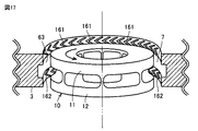
図16は、動圧溝を設ける位置を変更したポンプ部1の第1変形例の要部を示す断面図である。この図16と図3とは対比される図である。図16において、この遠心式ポンプ装置が図3の遠心式ポンプ装置と異なる点は、インペラ10の外周面に対向するポンプ室7の内周面に動圧溝161,162が形成されている点である。動圧溝161,162は、インペラ10の外周面に対する動圧力を発生し、インペラ10の外周面がポンプ室7の内周面に接触することを防止する。
[Modification of dynamic pressure groove]
FIG. 16 is a cross-sectional view illustrating a main part of a first modification of the
図17は、動圧溝161,162の具体的構成を例示する図である。図17において、ポンプ室7の内周面のうちのシュラウド11の外周面に対向する領域には、V字型の動圧溝161がインペラ10の回転方向に所定のピッチで形成されている。V字型の動圧溝161の先端(鋭角部)はインペラ10の回転方向に向けられている。同様に、ポンプ室7の内周面のうちのシュラウド12の外周面に対向する領域には、V字型の動圧溝162がインペラ10の回転方向に所定のピッチで形成されている。V字型の動圧溝162の先端(鋭角部)はインペラ10の回転方向に向けられている。ポンプ室7の内周面のうちのシュラウド11,12の隙間に対向する領域には、所定深さの溝63がリング状に形成されている。インペラ10が矢印の方向に回転すると、動圧溝161,162の先端部に向けて液体の圧力が高くなる。このため、インペラ10とポンプ室7の内周面との間に反発力が発生し、これが動圧力となる。
FIG. 17 is a diagram illustrating a specific configuration of the
図18は、図17の動圧溝の形状の変形例を示す図である。図18において、この変形例では、動圧溝161,162がそれぞれ動圧溝164,165で置換されている。動圧溝164,165の各々は、帯状に形成され、インペラ10の回転方向に延在している。動圧溝164,165の各々の深さは、インペラ10の回転方向に向かって徐々に浅くなっている。この変形例でも、インペラ10が矢印の方向に回転すると、動圧溝164,165の先端部に向けて液体の圧力が高くなる。このため、インペラ10とポンプ室7の内周面との間に反発力が発生し、これが動圧力となる。
FIG. 18 is a diagram showing a modification of the shape of the dynamic pressure groove in FIG. In FIG. 18, in this modification, the
図19〜図22は、動圧溝を設ける位置を変更したポンプ部1の第2〜第5変形例の要部を示す断面図である。図19、図20に示すように、動圧溝21を隔壁6に設ける代わりに、動圧溝121をインペラ10のシュラウド12の表面に設けてもよい。また、動圧溝22をポンプ室7の内壁側に設ける代わりに、動圧溝122をインペラ10のシュラウド11の表面に設けてもよい。
19-22 is sectional drawing which shows the principal part of the 2nd-5th modification of the
さらに、図19に示すようにインペラ10の外周面に動圧溝61,62を形成してもよい。また図20に示すようにインペラ10の外周面に対向するポンプ室7の外周壁に動圧溝161,162を形成してもよい。これらによりインペラのラジアル方向の支持力を発生させることができる。
Furthermore, as shown in FIG. 19,
また、図21に示すように、動圧溝61,62をインペラのシュラウド11,12の外周面に設ける代わりに、動圧溝261,262をインペラ10のシュラウド11,12の内周面表面に設けてもよい。
Further, as shown in FIG. 21, instead of providing the
また、図22に示すように、動圧溝161,162をポンプ室7の外周壁に設ける代わりに、動圧溝361,362をインペラ10のポンプ室7の内周壁に設けてもよい。
Further, as shown in FIG. 22, instead of providing the
以上説明したように、本実施の形態によれば、固定子と回転子の間に隔壁を備えたキャンドモータにおいて、駆動部9や永久磁石等による吸引力(負剛性成分)を無くすことができ、インペラの安定浮上回転が可能となる。さらにコギングの低減が図れ、スムーズな回転始動が実現できる。
As described above, according to the present embodiment, in the canned motor provided with the partition wall between the stator and the rotor, it is possible to eliminate the attractive force (negative stiffness component) by the
最後に、再び図3、図16、図19〜図22を参照して、本実施の形態を総括する。本実施の形態の遠心ポンプ装置は、ハウジング2とインペラ10と駆動部9と、複数の永久磁石17とを含む。
Finally, this embodiment will be summarized with reference to FIGS. 3, 16, and 19 to 22 again. The centrifugal pump device of the present embodiment includes a
ハウジング2は、隔壁6で仕切られたモータ室8およびポンプ室7を含む。インペラ10は、ポンプ室7内において隔壁6に交差する軸を回転軸として回転可能に設けられ、回転時の遠心力によって液体を送る。駆動部9は、モータ室8内に設けられ、隔壁6を介してインペラ10を回転駆動させる。複数の永久磁石17は、隔壁6に沿うインペラ10の一方面に設けられ、同一の円に沿って配置される。
The
駆動部9は、複数の永久磁石17にそれぞれ対向して設けられ、回転磁界を生成するための複数の空芯コイル20を含む。インペラ10の一方面と反対側の他方面またはそれに対向するポンプ室7の内壁に動圧溝22または122が形成され、インペラの一方面またはそれに対向する隔壁6に動圧溝21または121が形成され、インペラ10の外周面もしくはそれに対向するポンプ室7の内周面、またはインペラ10の内周面もしくはそれに対向するポンプ室7の外周面に動圧溝61,62,161,162,261,262,361,362が形成されている。
The
今回開示された実施の形態はすべての点で例示であって制限的なものではないと考えられるべきである。本発明の範囲は上記した説明ではなくて特許請求の範囲によって示され、特許請求の範囲と均等の意味および範囲内でのすべての変更が含まれることが意図される。 The embodiment disclosed this time should be considered as illustrative in all points and not restrictive. The scope of the present invention is defined by the terms of the claims, rather than the description above, and is intended to include any modifications within the scope and meaning equivalent to the terms of the claims.
1 ポンプ部、2 ハウジング、3 本体部、4 流入ポート、5 流出ポート、6 隔壁、7 ポンプ室、8 モータ室、10 インペラ、10a 貫通孔、11,12 シュラウド、13 ベーン、14 通路、17,17A,17B,67,67A,67B 永久磁石、18 空芯部、19,70A,70B,72 磁性体、20 空芯コイル、21,22,61,62,64,65,121,122,161,162,261,262,361,362 動圧溝。
DESCRIPTION OF
Claims (3)
前記第1の室内において前記隔壁に交差する軸を回転軸として回転可能に設けられ、回転時の遠心力によって液体を送るインペラと、
前記第2の室内に設けられ、前記隔壁を介して前記インペラを回転駆動させる駆動部と、
前記隔壁に沿う前記インペラの一方面に設けられ、同一の円に沿って配置された複数の第1の永久磁石とを備え、
前記駆動部は、前記複数の第1の永久磁石に対向して設けられ、回転磁界を生成するための複数の空芯コイルを含み、
前記インペラの前記一方面と反対側の他方面またはそれに対向する前記第1の室の内壁に第1の動圧溝が形成され、前記インペラの前記一方面またはそれに対向する前記隔壁に第2の動圧溝が形成され、
前記インペラの外周面もしくはそれに対向する前記第1の室の内周面、または前記インペラの内周面もしくはそれに対向する前記第1の室の外周面に第3の動圧溝が形成されている、遠心式ポンプ装置。 A housing including first and second chambers partitioned by a partition;
An impeller that is rotatably provided with an axis that intersects the partition in the first chamber as a rotation axis, and that sends liquid by centrifugal force during rotation;
A drive unit provided in the second chamber and configured to rotationally drive the impeller via the partition;
A plurality of first permanent magnets provided on one surface of the impeller along the partition and disposed along the same circle;
The drive unit includes a plurality of air-core coils that are provided to face the plurality of first permanent magnets and generate a rotating magnetic field,
A first dynamic pressure groove is formed on the other surface of the impeller opposite to the one surface or on the inner wall of the first chamber facing the second surface, and a second wall is formed on the one surface of the impeller or the partition facing the second surface. A dynamic pressure groove is formed,
A third dynamic pressure groove is formed on the outer peripheral surface of the impeller or the inner peripheral surface of the first chamber facing the impeller, or the inner peripheral surface of the impeller or the outer peripheral surface of the first chamber facing the impeller. , Centrifugal pump device.
Priority Applications (2)
| Application Number | Priority Date | Filing Date | Title |
|---|---|---|---|
| JP2015068560A JP2016188591A (en) | 2015-03-30 | 2015-03-30 | Centrifugal pump device |
| PCT/JP2016/056377 WO2016158172A1 (en) | 2015-03-30 | 2016-03-02 | Centrifugal pump device |
Applications Claiming Priority (1)
| Application Number | Priority Date | Filing Date | Title |
|---|---|---|---|
| JP2015068560A JP2016188591A (en) | 2015-03-30 | 2015-03-30 | Centrifugal pump device |
Publications (1)
| Publication Number | Publication Date |
|---|---|
| JP2016188591A true JP2016188591A (en) | 2016-11-04 |
Family
ID=57239639
Family Applications (1)
| Application Number | Title | Priority Date | Filing Date |
|---|---|---|---|
| JP2015068560A Pending JP2016188591A (en) | 2015-03-30 | 2015-03-30 | Centrifugal pump device |
Country Status (1)
| Country | Link |
|---|---|
| JP (1) | JP2016188591A (en) |
Cited By (1)
| Publication number | Priority date | Publication date | Assignee | Title |
|---|---|---|---|---|
| CN114923666A (en) * | 2022-06-14 | 2022-08-19 | 西安交通大学 | Outer loop transmission type circulating water tunnel |
Citations (4)
| Publication number | Priority date | Publication date | Assignee | Title |
|---|---|---|---|---|
| JPH04112994A (en) * | 1990-08-31 | 1992-04-14 | Ntn Corp | Turbo pump |
| JPH08144987A (en) * | 1994-11-18 | 1996-06-04 | Ebara Corp | Centrifugal motor pump |
| JP2012062790A (en) * | 2010-09-14 | 2012-03-29 | Ntn Corp | Centrifugal pump unit |
| EP2719403A1 (en) * | 2012-10-12 | 2014-04-16 | Abiomed Europe GmbH | Centrifugal blood pump |
-
2015
- 2015-03-30 JP JP2015068560A patent/JP2016188591A/en active Pending
Patent Citations (4)
| Publication number | Priority date | Publication date | Assignee | Title |
|---|---|---|---|---|
| JPH04112994A (en) * | 1990-08-31 | 1992-04-14 | Ntn Corp | Turbo pump |
| JPH08144987A (en) * | 1994-11-18 | 1996-06-04 | Ebara Corp | Centrifugal motor pump |
| JP2012062790A (en) * | 2010-09-14 | 2012-03-29 | Ntn Corp | Centrifugal pump unit |
| EP2719403A1 (en) * | 2012-10-12 | 2014-04-16 | Abiomed Europe GmbH | Centrifugal blood pump |
Cited By (1)
| Publication number | Priority date | Publication date | Assignee | Title |
|---|---|---|---|---|
| CN114923666A (en) * | 2022-06-14 | 2022-08-19 | 西安交通大学 | Outer loop transmission type circulating water tunnel |
Similar Documents
| Publication | Publication Date | Title |
|---|---|---|
| JP5577506B2 (en) | Centrifugal pump device | |
| JP5656835B2 (en) | Rotation drive device and centrifugal pump device using the same | |
| JP5681403B2 (en) | Centrifugal pump device | |
| JP5378010B2 (en) | Centrifugal pump device | |
| JP5969979B2 (en) | Rotation drive device and centrifugal pump device using the same | |
| US9366261B2 (en) | Centrifugal pump device | |
| JP5443197B2 (en) | Centrifugal pump device | |
| JP5378012B2 (en) | Centrifugal pump device | |
| JP5577503B2 (en) | Centrifugal pump device | |
| WO2016158173A1 (en) | Centrifugal pump device | |
| JP2016188591A (en) | Centrifugal pump device | |
| JP2016188593A (en) | Centrifugal pump device | |
| JP6452518B2 (en) | Centrifugal pump device | |
| WO2016158172A1 (en) | Centrifugal pump device | |
| JP5693812B2 (en) | Centrifugal pump device | |
| JP5378060B2 (en) | Centrifugal pump device | |
| JP6698278B2 (en) | Centrifugal pump device | |
| WO2016158185A1 (en) | Centrifugal pump device | |
| JP2012013043A (en) | Rotary drive device and centrifugal pump device using the same |
Legal Events
| Date | Code | Title | Description |
|---|---|---|---|
| A621 | Written request for application examination |
Free format text: JAPANESE INTERMEDIATE CODE: A621 Effective date: 20180226 |
|
| A131 | Notification of reasons for refusal |
Free format text: JAPANESE INTERMEDIATE CODE: A131 Effective date: 20181204 |
|
| A521 | Request for written amendment filed |
Free format text: JAPANESE INTERMEDIATE CODE: A523 Effective date: 20190129 |
|
| A02 | Decision of refusal |
Free format text: JAPANESE INTERMEDIATE CODE: A02 Effective date: 20190625 |