JP2016185192A - Ophthalmologic apparatus, and control method of ophthalmologic apparatus - Google Patents
Ophthalmologic apparatus, and control method of ophthalmologic apparatus Download PDFInfo
- Publication number
- JP2016185192A JP2016185192A JP2015066024A JP2015066024A JP2016185192A JP 2016185192 A JP2016185192 A JP 2016185192A JP 2015066024 A JP2015066024 A JP 2015066024A JP 2015066024 A JP2015066024 A JP 2015066024A JP 2016185192 A JP2016185192 A JP 2016185192A
- Authority
- JP
- Japan
- Prior art keywords
- eye
- image
- examined
- fundus
- shift amount
- Prior art date
- Legal status (The legal status is an assumption and is not a legal conclusion. Google has not performed a legal analysis and makes no representation as to the accuracy of the status listed.)
- Pending
Links
Images


Abstract
Description
本発明は、特に眼科診療等に用いられる眼底カメラに例示される眼科装置及びその制御方法に関するものである。 The present invention relates to an ophthalmologic apparatus exemplified by a fundus camera used for ophthalmic medical care and the like, and a control method thereof.
従来の眼底カメラの照明光学系では、被検眼の前眼部付近において、撮影光束と照明光束とを分離している。このため、被検眼の瞳孔付近、或いはその前後の例えば水晶体の後面付近に結像する光軸を含む周辺に、遮光領域を有しリング状の開口である遮光絞りを設けている。これにより、被検者の瞳孔径が遮光領域よりも大きい場合には、適正な明るさの画像が得られる。しかし、瞳孔径が遮光領域よりも小さい被検者の場合は、照明光束が虹彩により制限されることから、眼底画像の中心付近が暗くなってしまう。 In the conventional illumination optical system of the fundus camera, the imaging light beam and the illumination light beam are separated in the vicinity of the anterior eye portion of the eye to be examined. For this reason, a light-shielding stop that has a light-shielding region and is a ring-shaped opening is provided in the vicinity of the pupil of the eye to be examined or in the vicinity including the optical axis that is imaged in the vicinity of, for example, the back surface of the crystalline lens. Thereby, when the pupil diameter of the subject is larger than the light shielding area, an image with appropriate brightness can be obtained. However, in the case of a subject whose pupil diameter is smaller than the light-shielding region, the illumination light flux is limited by the iris, so that the vicinity of the center of the fundus image becomes dark.
この問題に対処するために、異なる大きさの遮光絞りを設け、瞳孔径の小さい被検眼を撮影する際には、遮光領域が大きく照明光が通過する開口の小さい遮光絞り(以下小さい小絞りと称する。)に交換して撮影する構成が特許文献1において提案されている。このような構成では、開口の大きい遮光絞り(以下大きい遮光絞りと称する。)を小さい遮光絞りに交換するには検者が切替えスイッチによって切り替えることが一般的である。 In order to cope with this problem, when providing a light-shielding stop of a different size and photographing an eye to be examined having a small pupil diameter, the light-shielding stop having a large light-shielding area and a small aperture through which illumination light passes (hereinafter referred to as a small small stop). In Japanese Patent Application Laid-Open No. 2004-228688, a configuration for taking an image by exchanging the image is proposed. In such a configuration, in order to replace a light-shielding diaphragm having a large opening (hereinafter referred to as a large light-shielding diaphragm) with a small light-shielding diaphragm, it is common for the examiner to switch with a changeover switch.
当該装置では、眼底カメラでオートフォーカスをするにあたってスプリット指標が虹彩によって遮られて検出できなかったと装置が判定すると、小さい遮光絞りに切り替えている。また、この小さい遮光絞りを用いたためにスプリット指標となる輝線が検出できない場合、位置合せマークの表示位置を中央部からずらした位置に変更してアライメントを行っている。このアライメントの光軸をずらす構成としては、前眼部の混濁の影響を避けるために、前眼部の徹照画像を用いたものが例えば特許文献2に開示されている。
In this apparatus, when the apparatus determines that the split index is not detected due to being blocked by the iris when performing autofocus with the fundus camera, the apparatus switches to a small light-shielding diaphragm. In addition, when a bright line as a split indicator cannot be detected due to the use of this small light blocking stop, alignment is performed by changing the display position of the alignment mark to a position shifted from the center. As a configuration for shifting the optical axis of this alignment, for example,
前述した従来から公知の構成では、通常の大きさの遮光絞りと瞳孔の小さい被検眼を撮影するために小さい遮光絞り、及びこれらを切り替える駆動機構を備える必要がある。このため、装置を製造する際のコストが上がってしまう。また、小さな遮光絞りに切換えた場合であっても、被検眼瞳孔がそれよりも小さい場合には依然として中心付近が暗い眼底画像しか得られない。特許文献1においては、このような画像上の問題については言及されていない。
また、アライメント目標位置を変更する際の変更量が、画像上の問題を考慮せずに一律に定められている。従って、アライメントを調整したとしても、暗い領域を適切に減少させることは容易ではない。更に、光軸をずらすことに関する特許文献2に開示される構成においても、実際の画像から光軸の位置が混濁領域内であるか否かを判断して当該領域を避けて光軸位置を定めており、ずらす量が画像を見る検者により一定しない可能性が有った。
In the above-described conventionally known configuration, it is necessary to provide a light shielding diaphragm having a normal size, a small light shielding diaphragm for photographing a subject eye having a small pupil, and a drive mechanism for switching between these. For this reason, the cost at the time of manufacturing an apparatus will go up. In addition, even when switching to a small shading stop, if the eye pupil to be examined is smaller than that, only a fundus image with a dark center can still be obtained.
In addition, the amount of change when changing the alignment target position is uniformly determined without considering image problems. Therefore, even if the alignment is adjusted, it is not easy to appropriately reduce the dark area. Furthermore, even in the configuration disclosed in
本発明はこのような状況に鑑みて為されたものであって、瞳孔の小さな被検眼の眼底の検査に際し、小瞳孔絞りである小さい遮光絞りを用いることなく、被検眼眼底画像において中心周囲が暗くなることを抑制しつつ好適なアライメントのずらし量を取得可能な眼科装置及びその制御方法の提供を目的とする。 The present invention has been made in view of such a situation, and when examining the fundus of a subject's eye having a small pupil, the center periphery of the subject's fundus image can be obtained without using a small light-shielding aperture that is a small pupil aperture. An object of the present invention is to provide an ophthalmologic apparatus capable of acquiring a suitable alignment shift amount while suppressing darkening, and a control method thereof.
本発明は、つぎのように構成した眼科装置を提供するものである。
即ち、本発明の眼科装置は、
照明された被検眼の前眼像を撮る前眼撮像手段を含む光学ヘッドと、
前記前眼像の瞳孔領域を検出する検出手段と、
前記検出された瞳孔領域のサイズ情報に基づいて、前記被検眼に対する前記光学ヘッドのアライメント目標位置のずらし量を算出する算出手段と、
を有することを特徴とすると、を有することを特徴とする。
The present invention provides an ophthalmologic apparatus configured as follows.
That is, the ophthalmic apparatus of the present invention is
An optical head including an anterior eye imaging means for taking an anterior eye image of the illuminated eye to be examined;
Detecting means for detecting a pupil region of the anterior eye image;
Calculation means for calculating a shift amount of the alignment target position of the optical head with respect to the eye to be examined based on the size information of the detected pupil region;
It is characterized by having.
本発明によれば、瞳孔の小さな被検眼の眼底の検査に際し、小瞳孔絞りである小さい遮光絞りを用いることなく、被検眼眼底画像において中心周囲が暗くなることを抑制しつつ好適なアライメントのずらし量を取得することが可能となる。 According to the present invention, when inspecting the fundus of a subject's eye having a small pupil, a suitable alignment shift is performed while suppressing the darkening of the center periphery of the subject's fundus image without using a small light-shielding aperture that is a small pupil aperture. The amount can be acquired.
以下、本発明の実施例について、図面を参照して説明する。なお、以下の実施例は特許請求の範囲に関わる本発明を限定するものではなく、また、本実施例で説明されている特徴の組み合わせの全てが本発明の解決手段に必須のものとは限らない。 Embodiments of the present invention will be described below with reference to the drawings. The following embodiments do not limit the present invention related to the scope of claims, and all combinations of features described in the embodiments are not necessarily essential to the solution means of the present invention. Absent.
本発明の実施例1に関し、本発明を適用した眼科装置の一例である眼底カメラについて、その構成を模式的に示す図1を用いて説明する。 A fundus camera that is an example of an ophthalmologic apparatus to which the present invention is applied will be described with reference to FIG.
図1は本特許の特徴を現した眼底カメラの光学ヘッド部Hの構成を示す模式図である。 FIG. 1 is a schematic diagram showing a configuration of an optical head portion H of a fundus camera showing the features of this patent.
該眼底カメラは、眼底を観察する照明光を発する眼底照明光源、及び眼底を撮影する照明光を発する撮影用光源を有する。本実施例において、観察用照明光源は近赤外光LED10が複数個配列されて取付けられたものより構成され、撮影用照明光源は白色を発光する可視光LED31が複数個配列されて取り付けられたものより構成されている。これら光源から発せられた照明光は、後で詳述する穴あきミラー2により反射され、被検眼Eと対向して配置される対物レンズ1を介して被検眼Eに導かれる。
The fundus camera includes a fundus illumination light source that emits illumination light for observing the fundus and a photographing light source that emits illumination light for photographing the fundus. In this embodiment, the observation illumination light source is composed of a plurality of near-
穴あきミラー2から可視光LED31に至る光路上には、角膜絞り14、リレーレンズ12、黒点板13、リレーレンズ11、分岐ミラー6、水晶体絞り7、及び瞳絞り15が配置される。角膜絞り14は、照明光束による被検眼角膜からの有害光(反射光)が撮影絞り3に入らないように、照明光束と撮影光束とを分離するためのリング状の開口部をもつ。黒点版13はリレーレンズ11及び12の間に配置され、表面反射に関して撮影絞りと共役な位置に黒点と呼ばれる小さな遮蔽物13aが配されたガラス板より構成される。
On the optical path from the
リレーレンズ11の後方に配置される分岐ミラー6は、近赤外光LED10への光路と可視光LED31への光路とに穴あきミラー2からの光路を分岐する。分岐ミラー6は可視光を反射し、近赤外光を透過するような特性をもつミラーであって光路中に固定されている。或いは、一般的な全反射特性をもって観察時には光路から退避しており、撮影時に光路内に挿入される、跳ね上げミラーより構成しても良い。
The branch mirror 6 disposed behind the
前述したように、照明光束と撮影光束とは、照明光束による被検眼水晶体からの有害光(反射光)が撮影絞り3に入らないように分離することを要する。このため、分岐ミラー6と近赤外光LED10との間には、リング状の開口部を有する水晶体絞り8及びリング状の開口部を有する瞳絞り9が配置される。該瞳絞り9は、被検眼瞳の位置と略共役の位置に配置される。
As described above, the illumination light beam and the photographing light beam need to be separated so that harmful light (reflected light) from the eye lens due to the illumination light beam does not enter the photographing
同様に、分岐ミラー6と可視光LED31との間にも同様な機能をもつ水晶体絞り7及び瞳絞り15が配置されている。なお、本実施例において可視光LED31は瞳絞り15の開口部と同径の円形に複数個のLEDが並べられ、構成されている。
Similarly, a
以上に述べた対物レンズ1から穴あきミラー2を介して観察用照明光源である近赤外光LED10及び可視光LED31に至る光路上に配置された光学部材からなる光学系により、本実施例における照明光学系を構成している。該照明光学系は、被検眼の眼底を照明する。
In the present embodiment, the optical system comprising the optical member arranged on the optical path from the
本眼底カメラにおいては、穴あきミラー2の後方には、撮影絞り3、フォーカスレンズ20、結像レンズ21、跳ね上げミラー22、及び撮像手段23がこの順にて配置されている。跳ね上げミラー22は、撮影時にはミラーが跳ね上がり光路から退避する。撮像手段23は、撮影時に被検眼眼底像を撮像する可視域に感度を有する。これら対物レンズ1から撮像手段23に至る光路上に配置された光学部材からなる光学系により、本発明における撮影光学系即ち眼底観察撮影光学系を構成している。
In this fundus camera, an
また、該眼底カメラは、跳ね上げミラー22を光路に侵入させた際の反射方向において、内部固視標24を有する。該内部固視標24は被検眼の固視を誘導するために用いられ、眼底と略共役となる位置に配置されている。
Further, the fundus camera has an
更に、該眼底カメラは、対物レンズ1と穴あきミラー2との間に配置されるダイクロイックミラー25及び、被検眼Eの前眼部等を照明する照明光源28を有する。照明光源28は、被検眼Eを照明するために対物レンズ1の回りに複数個配置され、前述した近赤外光LED10と波長の異なる赤外波長を有する赤外光を発する。ダイクロイックミラー25は、これら複数の照明光源28によって照明された被検眼Eの反射光を反射し、その他の波長を透過する特性を有している。
The fundus camera further includes a
ダイクロイックミラー25の反射方向の光軸上には、平板46、結像レンズ26、及び撮像手段27がこの順で配置され、前眼観察光学系を構成している。撮像手段27は、照明された被検眼の前眼像を撮る前眼撮像手段を構成する。平板46は中心部にイメージスプリットプリズムを有し、対物レンズ1によって被検眼Eの前眼部と共役となる位置に配置される。なお、本実施例では、イメージスプリットプリズムとして、フレネルプリズムを用いている。撮像手段27に撮像される前眼部の画像は図2のように不図示の表示手段たるモニタに表示される。即ち、前眼観察光学系は、被検眼の前眼像を得るために用いられる。
On the optical axis in the reflection direction of the
なお、該眼底カメラは、更に、後述するアライメント駆動手段29、アライメント状態検出手段44、制御手段45、アライメント目標変更手段47、及び画像生成手段48を有する。アライメント状態検出手段44は、アライメント検出手段として、撮像手段26からの出力をうけ、被検眼Eと光学ヘッドHとのアライメント状態を検出してこれを制御手段45に出力する。撮像手段23の出力は制御手段45を介して画像生成手段48に伝達され、該画像生成手段48により生成された各画像は制御手段45による不図示のモニタに表示される。内部固視標24は、例えば平板面上の任意の位置に固視灯を点灯可能であって、制御手段45によりその点灯位置が制御されて被検眼Eの適当な固視を促す。なお、アライメント駆動手段29は、本実施例において被検眼Eと光学ヘッドHとのアライメントを行うアライメント手段を構成する。
The fundus camera further includes an
次に、前眼部画像を用いた光学ヘッド部Hと被検眼Eとのアライメントについて詳述する。被検眼Eに対する光学ヘッド部Hのアライメント位置がXYZ方向(X:被検眼Eに対して左右方向であって、図の紙面に垂直な方向。Y:被検眼Eに対して上下方向であって、図の紙面に平行な方向。Z:被検眼に対し遠近方向であって、図の紙面に平行な方向)ともに適正位置でない場合には図3に示した前眼画像になる。この段階では前眼画像は上下でスプリットしておらず、瞳孔Epの中心が画像中心からずれて表示されている。前眼部がスプリットしていないのはイメージスプリット部から外れているためである。 Next, the alignment between the optical head unit H and the eye E using the anterior segment image will be described in detail. The alignment position of the optical head H with respect to the eye E is in the XYZ directions (X: the left-right direction with respect to the eye E, and the direction perpendicular to the paper surface of the drawing. Y: the vertical direction with respect to the eye E) The direction parallel to the paper surface of the figure, Z: the perspective direction with respect to the eye to be examined and the direction parallel to the paper surface of the figure) is not an appropriate position, the anterior eye image shown in FIG. At this stage, the anterior eye image is not split up and down, and the center of the pupil Ep is displayed shifted from the center of the image. The anterior eye part is not split because it is out of the image split part.
本実施例では、光学ヘッド部Hのアライメント位置がXY方向には適正位置にあり且つZ方向に遠い場合には、図4に示すように、前眼画像は上下でスプリットした上で更に上部が右側に、下部が左側にずれて表示される。また、光学ヘッド部Hのアライメント位置がXY方向には適正位置にあり且つZ方向に近い場合には図5に示すように、上部が左側に、下部が右側にずれて表示される。 In this embodiment, when the alignment position of the optical head portion H is at an appropriate position in the XY direction and is far from the Z direction, the anterior eye image is split up and down as shown in FIG. On the right side, the lower part is displayed shifted to the left side. Further, when the alignment position of the optical head portion H is at an appropriate position in the XY direction and close to the Z direction, the upper portion is displayed on the left side and the lower portion is displayed on the right side as shown in FIG.
前述したように、撮像手段27で撮像された前眼画像に示す信号はアライメント状態検出手段44へ出力される。アライメント状態検出手段44では前述した図2〜5に示すような画像から現在の光学ヘッド部Hのアライメント状態がXYZ方向においてどの位ずれているのかを検出する。その検出結果と撮像手段27で撮像された画像とは、更に制御手段45へ出力される。
As described above, the signal shown in the anterior eye image captured by the
光学ヘッド部Hは、図示しないステージに搭載されている。制御手段45は、アライメント状態検出手段44の検出結果から、光学ヘッド部HをXYZ方向へそれぞれ移動させる量を算出する。アライメント駆動手段29は、ステージを駆動することによって被検眼Eに対して光学ヘッド部Hを光軸(Z)方向、及び偏心(XY)方向に移動し、光学ヘッド部Hのアライメントを行う。また、撮像手段27で撮像された前眼画像は、アライメント目標変更手段47へ出力される。
The optical head portion H is mounted on a stage (not shown). The
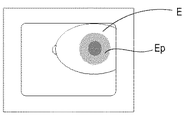
次に、被検眼Eの各位置において結像される絞りの各々について、図6に基づいて説明する。 Next, each of the stops imaged at each position of the eye E will be described with reference to FIG.
被検眼Eと対物レンズ1との距離が適正に調整された場合には、角膜絞り14は被検眼Eの角膜頂点付近に、水晶体絞り7及び8は水晶体後面付近に、瞳絞り9及び15は瞳孔Ep付近に結像されている。これらの絞りを配置する目的は、撮影光束の通過領域内に照明光による水晶体或いは角膜での散乱及び反射を発生させないことである。例えば撮影光束の通過領域内で散乱光が発生すると、この散乱光は眼底像と同様の経路を経て撮像手段23に達する。これら散乱光は撮像手段23に対し、眼底像上にて白い雲のようなフレアとして写り込み、眼底像のコントラストを低下させたり、眼底像を覆い隠したりする。
When the distance between the eye E and the
図6に示した状態では、瞳孔Epが十分開いている場合であるので瞳孔Epが照明光束を遮ることがなく、眼底中心付近も照明されている。なお、本実施例における前述した各絞りにおける前眼上での画像について、各々の像である水晶体絞り像7’及び8’、瞳絞り像9’及び15’、及び角膜絞り像14’の大きさを図15である表に示す。
In the state shown in FIG. 6, since the pupil Ep is sufficiently open, the pupil Ep does not block the illumination light beam, and the vicinity of the fundus center is illuminated. In addition, regarding the image on the anterior eye at each of the above-described apertures in the present embodiment, the sizes of the
次に、本実施例1に係るオートアライメント機能を有した眼底カメラにおいて、眼底を撮像する際の動作を図13に示すフローチャートに従って説明する。 Next, in the fundus camera having the auto-alignment function according to the first embodiment, the operation when imaging the fundus will be described with reference to the flowchart shown in FIG.
まず、検者が不図示の撮影開始スイッチを押す(S1)。
S2で、撮影開始スイッチからの信号を受けた制御手段45は、被検眼Eと光学ヘッド部Hとの位置合せを開始する。アライメント目標位置は初期(偏心がない)位置となっている。撮像手段27によって図3に例示する画像が取得されると、アライメント状態検出手段44は、例えば画像を二値化して瞳孔を検出し、その重心位置から光学ヘッド部Hの被検眼Eに対するXY方向の偏心量を算出する。制御手段45はこの算出結果を受け、偏心量をキャンセルするようにアライメント駆動手段29によって光学ヘッド部HをXY方向に動かす。
First, the examiner presses an imaging start switch (not shown) (S1).
In S <b> 2, the
XY方向の位置合せが終了して前眼部の表示が図4に例示する状態になると、フローはS3に移行する。ここで、アライメント状態検出手段44は前眼像のスプリット像が示すずれの方向から光学ヘッド部Hが被検眼Eに対してZ方向において遠近何れにずれており、且つ該像のずれ量からどの程度のずれであるかを算出する。算出結果は、制御手段45に出力される。制御手段45は、そのずれ量をキャンセルするようにアライメント駆動手段29により光学ヘッド部HをZ方向に動かしアライメント動作を完了させる。 When the alignment in the XY directions is completed and the display of the anterior segment is in the state illustrated in FIG. 4, the flow proceeds to S3. Here, the alignment state detection means 44 detects whether the optical head portion H is shifted in the Z direction with respect to the eye E from the direction of shift indicated by the split image of the anterior eye image, and from the amount of shift of the image. The degree of deviation is calculated. The calculation result is output to the control means 45. The control means 45 moves the optical head portion H in the Z direction by the alignment driving means 29 so as to cancel the shift amount, and completes the alignment operation.
Z方向のアライメント動作が完了すると、フローはS4に移行する。S4ではアライメント目標位置が変更されているかの判定を制御手段45が行う。 When the alignment operation in the Z direction is completed, the flow moves to S4. In S4, the control means 45 determines whether the alignment target position has been changed.
この場合、変更されていないので、フローはS5へ移行する。S5では、制御手段45は、アライメント状態検出手段44から出力された前眼画像をアライメント目標変更手段47へ出力する。アライメント目標変更手段47は、入力された前眼画像から被検眼瞳孔径を計測する。より詳細には、瞳孔部分の直径相当の画素数を計測し、画素サイズ、及び前眼部の結像倍率から瞳孔径を算出する。ここでは、計測結果として、瞳孔径がΦ5だったと仮定する。
In this case, since it has not been changed, the flow moves to S5. In S <b> 5, the
S6では、S5で算出された瞳孔径Φ5と、図15のテーブルに示された前眼部に結像している角膜絞り像14’、瞳絞り像9’及び15’、水晶体絞り像7’及び8’各々の内径とを参照比較する。参照比較の結果、瞳孔径が大きく照明光束を遮っていないと判定された時には、フローはS7に移行する。このときの各絞り像、被検眼、及び照明光の状態は、図6に示したものとなる。なお、この検出された瞳孔領域のサイズ情報に基づいて被検眼が小瞳孔であるか否かを判定する操作は、制御手段45において判定手段として機能するモジュールにより実行される。
In S6, the pupil diameter Φ5 calculated in S5, the
S7では、撮影光学系のフォーカスレンズ20を光軸方向に駆動してピント合わせを行う。眼底への合焦が終了した後、続くS8で眼底の撮影を行ってフローは終了(S9)する。 In S7, focusing is performed by driving the focus lens 20 of the photographing optical system in the optical axis direction. After focusing on the fundus is completed, the fundus is photographed in subsequent S8, and the flow ends (S9).
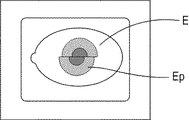
次にS6における参照比較の結果、図7に示されるように被検眼瞳孔Epが小さく、照明光束が遮られていると判定された場合について説明する。ここでは、瞳孔Epの径がΦ4.2と小さく、眼底を照明する照明光束が虹彩等によって遮られてしまい中心付近を照明する光束がなくなってしまっていると仮定する。仮にこの状態でアライメント、ピント合わせを行い、撮影を実行したとすると、得られる画像は図8に例示されるように中心付近が暗くなった画像になる。 Next, the case where it is determined as a result of the reference comparison in S6 that the eye pupil Ep to be examined is small and the illumination light beam is blocked as shown in FIG. Here, it is assumed that the diameter of the pupil Ep is as small as Φ4.2, and the illumination light beam that illuminates the fundus is blocked by the iris or the like, and the light beam that illuminates the vicinity of the center has disappeared. If alignment and focusing are performed in this state and photographing is performed, the obtained image is an image in which the vicinity of the center is dark as illustrated in FIG.
そこで、フローはS10へ移行する。S10において、アライメント目標変更手段47は内部固視標24の提示位置に基づいて、被検者の固視が光学ヘッド部Hの光軸よりも左右の何れに異なり傾いているかを検出する。そして、この検出結果に基づいて、アライメント目標位置をずらす方向の左右を決定する。このずらし方向の決定は、被検眼の固視の位置に応じてアライメント位置をずらす際のずらし方向を決定する方向決定手段として機能する制御手段45におけるモジュールにより実行される。さらにS11において、中心付近を照明する光束ができるように、図9(本図は左右を上方から見た図になっている。)に示すようにアライメント終了時のX方向の位置をずらすためのずらし量Dを決定する。算出されるアライメント目標位置のずらし量Dは眼底中心付近を照明する光束ができる量でもよいが、照明光束がなくなる位置が撮影範囲から外れるまでずらすことが望ましい。当該ずらし量Dのこのような算出工程は、制御手段45において算出手段として機能するモジュールにより実行され、前述した判定手段の判定結果に応じて開始される。本実施例において、該算出手段は、虹彩によって遮られる照明光の量を前眼像から検出することとなり、ずらし量はこの検出結果に基づいて算出される。より詳細には、撮像された前眼像の瞳孔径を検出し、この検出結果に基づいてずらし量を算出している。なお、この瞳孔径は、瞳孔領域のサイズ情報の一例であって、虹彩によって遮られる照明光の量を求めるために参照し得る種々の情報をこれに換えて用いることが可能である。また、瞳孔領域の検出は、制御手段45において前眼像の瞳孔領域を検出する検出手段として機能するモジュールにより実行される。
Therefore, the flow moves to S10. In S <b> 10, the alignment
なお、このずらし量Dは瞳孔Epの径等によってかわってくる。ここで例示している場合であれば、水晶体絞り像7’及び8’の内径はΦ4.5であるのでずらし量Dは少なくとも0.15以上が設定されることが好ましく、ここでは例えばD=0.3と設定される。
This shift amount D varies depending on the diameter of the pupil Ep and the like. In the case illustrated here, since the inner diameters of the
ずらし量Dが決定されるとその結果を制御手段45は受けて、フローはS12に進み、アライメント目標位置を初期位置からずらし量Dだけずらせた第一のアライメント目標に変更する。その後、フローはS2に戻る。以上のS6、及びS10〜S12の工程は、本実施例においてアライメント位置のアライメント目標位置に対するずらし方向及びずらし量を求める工程に対応し、当該工程は制御手段45において方向決定手段として機能するモジュール、及び算出手段とする機能するモジュールにより実行される。
When the shift amount D is determined, the control means 45 receives the result, and the flow advances to S12 to change the alignment target position to the first alignment target shifted by the shift amount D from the initial position. Thereafter, the flow returns to S2. The processes of S6 and S10 to S12 described above correspond to the process of obtaining the shift direction and shift amount of the alignment position with respect to the alignment target position in the present embodiment, and the process functions as a direction determining unit in the
S2では、変更したアライメント目標位置に対して、光学ヘッドHのXY方向についてのアライメントを行う。該アライメント終了後、S3にてZ方向のアライメント合せを行う。続くS4では、アライメント目標位置が変更されているか否かを再び判定する。今回はアライメント目標位置が変更されているので、フローはS13へ移行する。 In S2, the alignment of the optical head H in the XY directions is performed with respect to the changed alignment target position. After completion of the alignment, alignment in the Z direction is performed in S3. In subsequent S4, it is determined again whether or not the alignment target position has been changed. Since the alignment target position has been changed this time, the flow moves to S13.
S13ではフォーカスレンズ20によってピント合わせを行い、続くS14で第一のアライメント目標変更位置であるか否かの判定を行う。ここでは、第一のアライメント目標位置とした場合の眼底撮影であることから、フローはS15へ移行して眼底の撮影が行われる。撮影された眼底画像では、図8に示した画像中の暗い部分は存在していない。しかし、アライメント位置を左右方向にずらしたために、光学ヘッド部Hを移動させた方向と逆の方向に対応する位置にフレアFが入った眼底画像になっている。 In S13, focus is performed by the focus lens 20, and in S14, it is determined whether or not the position is the first alignment target change position. Here, since fundus photographing is performed when the first alignment target position is set, the flow proceeds to S15 and fundus photographing is performed. In the photographed fundus image, the dark part in the image shown in FIG. 8 does not exist. However, since the alignment position is shifted in the left-right direction, the fundus image has a flare F in a position corresponding to the direction opposite to the direction in which the optical head portion H is moved.
撮影後、続くS16において、アライメント目標変更手段47はS12で決定したずらし方向とずらし量Dに対して、逆方向にアライメント目標位置をずらすこととしてそのずらし量D’を算出して制御手段45に出力する。制御手段45は、このずらし方向とずらし量D’とに基づいて、第二のアライメント目標変更を行い第二のアライメント目標位置を設定する。S16にて第二のアライメント目標変更を行った後、フローはS2に戻ってS13のピント合わせまで前回と同様の工程を繰り返す。
After the photographing, in subsequent S16, the alignment target changing means 47 calculates the shift amount D 'by shifting the alignment target position in the opposite direction to the shift direction and shift amount D determined in S12, and sends it to the control means 45. Output. Based on the shifting direction and the shift amount D ′, the
続くS14において、再度直前に行われたアライメント操作の目標位置が第一のアライメント目標変更位置であったか否かの判定を行う。今回は第一のアライメント目標変更位置に対するアライメントではないので、フローはS17へ移行する。S17では、第二のアライメント目標変更位置にアライメントを行った状態での眼底の撮影が行わる。ここで撮影された眼底画像は、図11に示すように、先ほど得られた図10に示した画像とは反対側にフレアFが入った画像となる。撮影終了後、フローはS18に移行する。 In subsequent S14, it is determined whether or not the target position of the alignment operation performed immediately before is the first alignment target change position. Since this time is not the alignment with respect to the first alignment target change position, the flow proceeds to S17. In S17, photographing of the fundus is performed in a state where the alignment is performed at the second alignment target change position. As shown in FIG. 11, the fundus image photographed here is an image having flare F on the opposite side to the image shown in FIG. 10 obtained earlier. After the end of shooting, the flow moves to S18.
S18では、制御手段45からの指示に応じ、画像生成手段48が1回目の撮影で得られた図10に示す撮影画像と2回目の撮影で得られた図11に示す撮影画像との2枚の撮影画像を合成して、図12に例示したフレアFの入らない1枚の画像を作成する。ここで示した例における画像作成に際しては、例えば図10の画像におけるフレアFの入っていない左半分と図11の画像における右半分とを組み合わせることが考えられる。なお、この場合に切り取る方向は、ずらした方向から判定出来る。 In S18, in response to an instruction from the control means 45, the image generation means 48 takes two images, the photographed image shown in FIG. 10 obtained by the first photography and the photographed image shown in FIG. 11 obtained by the second photography. Are combined to create a single image without the flare F illustrated in FIG. When creating an image in the example shown here, for example, it is conceivable to combine the left half of the image of FIG. 10 without the flare F and the right half of the image of FIG. In this case, the cutting direction can be determined from the shifted direction.
本実施例では、アライメント目標位置変更手段が設定したアライメント目標位置にてS15において眼底像を得ている。また、該アライメント目標位置変更手段がアライメント目標位置を設定した際のずらし方向とは逆方向において該ずらし量分だけずらせた新たなアライメント目標位置にてS17において眼底像を得ている。撮像手段は、少なくともこれら眼底像を含む複数枚の眼底像を撮影する。S18では、画像生成手段48が、撮影された複数の眼底画像から1枚の眼底の画像を生成する。画像作成後、フローはS9に移行して眼底撮影の処理が終了する。
In this embodiment, the fundus image is obtained in S15 at the alignment target position set by the alignment target position changing means. Further, a fundus image is obtained in S17 at a new alignment target position shifted by the shift amount in the direction opposite to the shift direction when the alignment target position changing means sets the alignment target position. The imaging means captures a plurality of fundus images including at least these fundus images. In S <b> 18, the
なお、以上の例ではS10において固視標が固視を左右方向に動かし、アライメントを左又は右にずらすように提示されていた場合について述べている。しかし、S10において固視標が上下方向に関して提示されていた場合にはS11においてずらす方向は上又は下の方向になり、斜め方向であればその方向についてずらすことになることは言うまでもない。
また、以上のフローは制御手段45によって自動で行われるが、S10においてユーザによって以降のステップを実行する小瞳孔モードの実行を指示することとしてよい。或いは当該フローが小瞳孔モードを実行するモードであるとしてのその実行をユーザが指示する態様としても良い。この場合、該小瞳孔モードの実行の指示を行うボタン等の指示手段を制御手段45に配することが好ましい。
In the above example, the case where the fixation target is presented to move the fixation in the left-right direction and shift the alignment left or right in S10 is described. However, when the fixation target is presented in the vertical direction in S10, it goes without saying that the direction to be shifted in S11 is the upward or downward direction, and in the oblique direction, the direction is shifted.
Moreover, although the above flow is automatically performed by the control means 45, in S10, it is good also as instruct | indicating execution of the small pupil mode which performs a subsequent step by the user. Or it is good also as an aspect which a user instruct | indicates the execution that the said flow is a mode which performs the small pupil mode. In this case, it is preferable that an instruction unit such as a button for instructing execution of the small pupil mode is arranged in the
また、本実施例では、水晶体絞り7及び8は被検眼瞳孔径によらず変更していない。しかし、水晶体絞りの内側の遮蔽部を小さくした絞りを更に備えることとして、瞳孔径が小さい場合にはまず水晶体絞り7及び8を切り替えたうえで眼底中心付近を照明する光束の有無を判定し、アライメント位置を変更する構成にしてもよい。この場合、被検眼の水晶体の後面に像を投影して光学ヘッドHにおける第一の遮光領域からなるリング状開口を有す第一の遮光絞りがこれら水晶体絞り7及び8に対応する。これら水晶体絞りは、遮光領域が第一の遮光領域よりも小さい第二の遮光領域を有する第二の遮光絞りと該第一の遮光絞りとを切換え可能であって、制御手段45に含まれて制御されることが好ましい。さらに、この場合、制御手段45は、アライメント目標変更手段によるアライメント目標位置の変更があった場合に、第一の遮光絞りを第二の遮光絞りに変更して、再度アライメント目標変更手段によるずらし量を算出する制御を行うことが好ましい。これにより、より好適な眼底像の取得が可能となる。
Further, in the present embodiment, the
ここで、瞳孔径が小さい被検者を通常の大きい遮光絞りで撮影すると、フレアと言われる不要光が入ることはない。しかし、前述した通り眼底画像の中心付近が暗くなってしまう。一方、小さい遮光絞りを用いた場合では中心付近が暗くなることがないが、フレアが眼底画像の周辺部にはいってしまう。よって、それぞれの画像は良好な画像とは言えない。 Here, when a subject having a small pupil diameter is photographed with a normal large light-shielding diaphragm, unnecessary light called flare does not enter. However, as described above, the vicinity of the center of the fundus image becomes dark. On the other hand, when a small shading stop is used, the vicinity of the center does not become dark, but flare enters the periphery of the fundus image. Therefore, it cannot be said that each image is a good image.
例えば、瞳孔が小さい被検者の場合に、大きい遮光絞りで撮影した画像と、小さい遮光絞りで撮影した画像から1枚の画像を合成することで、これに対処することも可能である。当該構成では、通常の遮光絞りで撮影した画像から周辺部を、小さい遮光絞りで撮影した画像から中心部を切出して1枚の良好な眼底画像を得る構成になっている。 For example, in the case of a subject having a small pupil, it is possible to cope with this by combining one image from an image photographed with a large shading stop and an image photographed with a small shading stop. In this configuration, a peripheral portion is cut out from an image photographed with a normal light-shielding diaphragm, and a central portion is cut out from an image photographed with a small light-shielding diaphragm to obtain one good fundus image.
ここで、このような画像中の暗い領域への対応を目的とした構成では、遮光絞りをかえて撮影した2枚の画像から1枚の良好な画像を合成することを要する。しかし、遮光絞りの大きさを変えると各眼底位置を照明する光量が変わる(像面照度比)ので画像の合せ目が目立たないように複雑な画像処理を行う必要がある。本発明によれば、同じ遮光絞りを用いて得た複数の画像を合成して1枚の画像を得ることから、合せ目に留意せずとも良好な画像が得られる。 Here, in the configuration aiming at dealing with such a dark region in the image, it is necessary to synthesize one good image from two images taken by changing the light-shielding aperture. However, if the size of the light-shielding stop is changed, the amount of light that illuminates each fundus position changes (image plane illuminance ratio), so that it is necessary to perform complex image processing so that the image alignment is not noticeable. According to the present invention, since a single image is obtained by combining a plurality of images obtained using the same light-shielding diaphragm, a good image can be obtained without paying attention to the joint.
前述した実施例1では、ずらし量Dの決定は瞳孔Epの計測結果に基づいて行った。これに対し、本実施例2では、ずらし量Dを観察画像から決定することとしている。即ち、本実施例において、前述した算出手段は、被検眼の虹彩によって照明光学系の照明光を遮る量を眼底像から検出し、検出結果に基づいてずらす量を算出している。より詳細には、該算出手段は、眼底観察撮影光学系で撮像された眼底観察像を解析して暗部の大きさを検出し、検出結果に基づいてずらす量を算出している。なお、当該暗部は、眼底像における中央領域における輝度等の画素値の強度情報に基づいて求められる。また、暗部を求める際の中央領域の検出は、制御手段45において眼底像の中央領域を検出する検出手段として機能するモジュールにより実行される。 In Example 1 described above, the shift amount D is determined based on the measurement result of the pupil Ep. On the other hand, in the second embodiment, the shift amount D is determined from the observation image. In other words, in the present embodiment, the calculation means described above detects the amount of obstruction of the illumination light of the illumination optical system by the iris of the eye to be examined from the fundus image, and calculates the amount to shift based on the detection result. More specifically, the calculation means analyzes the fundus observation image captured by the fundus observation photographing optical system to detect the size of the dark part, and calculates the shift amount based on the detection result. Note that the dark part is obtained based on intensity information of pixel values such as luminance in the central region of the fundus image. Further, the detection of the central area when obtaining the dark part is executed by a module that functions as a detecting means for detecting the central area of the fundus image in the control means 45.
オートアライメント機能を有した眼底カメラにおいて、眼底を撮像する際の本実施例に係る動作を、図14に示すフローチャートに従って説明する。なお、実施例1と重複するステップについては図13と同じ参照番号を付記することとしてここでの説明を省略する。 In the fundus camera having the auto-alignment function, the operation according to the present embodiment when imaging the fundus will be described with reference to the flowchart shown in FIG. In addition, about the step which overlaps with Example 1, the same reference number as FIG. 13 is attached and description here is abbreviate | omitted.
まず、検者が不図示の撮影開始スイッチを押す(S1)。
S2で、撮影開始スイッチからの信号を受けた制御手段45は、被検眼Eと光学ヘッド部Hとの位置合せを開始する。アライメント目標位置は初期(偏心がない)位置となっている。ここでは、アライメント状態検出手段44は、撮像手段27により得られた前眼画像における瞳孔の重心位置から光学ヘッド部Hの被検眼Eに対するXY方向の偏心量を算出する。制御手段45はこの算出結果を受けて、偏心量をキャンセルするようにアライメント駆動手段29によって光学ヘッド部HをXY方向に動かす。
First, the examiner presses an imaging start switch (not shown) (S1).
In S <b> 2, the
XY方向の位置合せが終了して前眼部の表示が図4に例示する状態になると、フローはS3に移行する。ここで、アライメント状態検出手段44は前眼像のスプリット像が示すずれの方向から光学ヘッド部Hが被検眼Eに対してZ方向において遠近何れにずれており、且つ該像のずれ量からどの程度のずれであるかを算出する。算出結果は、制御手段45に出力される。制御手段45は、そのずれ量をキャンセルするようにアライメント駆動手段29により光学ヘッド部HをZ方向に動かしアライメント動作を完了させる。 When the alignment in the XY directions is completed and the display of the anterior segment is in the state illustrated in FIG. 4, the flow proceeds to S3. Here, the alignment state detection means 44 detects whether the optical head portion H is shifted in the Z direction with respect to the eye E from the direction of shift indicated by the split image of the anterior eye image, and from the amount of shift of the image. The degree of deviation is calculated. The calculation result is output to the control means 45. The control means 45 moves the optical head portion H in the Z direction by the alignment driving means 29 so as to cancel the shift amount, and completes the alignment operation.
Z方向のアライメント動作が完了すると、フローはS104に移行する。S104ではこれから行う撮影が2回目であるか否かを判定する。 When the alignment operation in the Z direction is completed, the flow moves to S104. In S104, it is determined whether or not the image capturing to be performed is the second time.
今回は1回目であるので、フローはS105へ移行する。S105において、撮像手段23で撮像された眼底観察画像を取得し、当該画像は制御手段45へ出力される。制御手段45は、アライメント目標変更手段47へ該画像を出力する。
Since this is the first time, the flow moves to S105. In step S <b> 105, the fundus observation image captured by the
続くS106では、瞳孔Epが好適な画像が得られるだけの大きさを有しているか否かを該画像に基づいて判定する。得られた眼底観察画像において、例えば図8に示す画像中の暗い部分が存在していなければ瞳孔Epは十分な大きさを有していると判定できる。この場合、暗い領域は存在していないためフローはS107に移行する。以上に述べた眼底像におけるフレア領域の大きさに基づいて被検眼が小瞳孔であるか否かを判定する操作は、制御手段45において判定手段として機能するモジュールにより実行される。 In subsequent S106, it is determined based on the image whether or not the pupil Ep has a size sufficient to obtain a suitable image. In the obtained fundus observation image, for example, if there is no dark portion in the image shown in FIG. 8, it can be determined that the pupil Ep has a sufficient size. In this case, since the dark area does not exist, the flow moves to S107. The operation for determining whether or not the eye to be examined is a small pupil based on the size of the flare area in the fundus image described above is executed by the module that functions as the determination means in the control means 45.
S107では、アライメント目標位置が変更されているか否かについて判定を行う。アライメント目標位置の変更は行われていないためフローはS7に移行し、ピント合わせから以降のS8の眼底像の撮像、S9のフローの終了へとフローは進められる。 In S107, it is determined whether or not the alignment target position has been changed. Since the alignment target position has not been changed, the flow moves to S7, and the flow proceeds from focusing to capturing of the fundus image in S8 and the end of the flow in S9.
一方、瞳孔Epが小さく、図8に示すような暗い領域が存在する眼底観察画像であった場合について、S106で行われる判定の処理について説明する。S106において、アライメント目標変更手段47は、例えば取得された画像の眼底画像領域に検出ウインドウを設定し、所定輝度値以下の画素領域を抽出する。その結果、所定輝度値より低い領域が存在していることが確認されると、画像中に暗い領域が存在するとしてフローはS10へ移行する。
On the other hand, the determination process performed in S106 will be described in the case where the pupil Ep is small and the fundus observation image has a dark region as shown in FIG. In S <b> 106, the alignment
S10では、実施例1の場合と同様に内部固視標24の提示位置に基づいてアライメント目標位置をずらす方向左右を決定する。続くS11でも同様に、アライメント終了時にX方向のずらす量を決定する。なお、本実施例において、S11では予め設定されている所定量のずらし量D(例えば0.1mm)を決定する。ずらし量Dが決定されるとその結果を制御手段45は受けて、フローはS12に移行する。S12では、アライメント目標位置を、初期位置から決定された方向にずらし量Dだけずらせた第一のアライメント目標に変更する。その後、フローはS2に移行する。以上のS106、及びS10〜S12の工程は、本実施例においてアライメント位置のアライメント目標位置に対するずらし方向及びずらし量を求める工程に対応し、当該工程は制御手段45において方向決定手段として機能するモジュール及び算出手段とする機能するモジュールにより実行される。
In S10, the right and left directions in which the alignment target position is shifted are determined based on the presentation position of the
S2では、変更したアライメント目標位置に対して、光学ヘッドHのXY方向についてのアライメントを行う。該アライメント終了後、S3にてZ方向のアライメント合せを行う。続くS104では、再度これから行う撮影が2回目であるか否かを判定する。現時点においてまだ撮影は実行されておらず、これから行う撮影は1回目であるので、フローはS105へ移行する。 In S2, the alignment of the optical head H in the XY directions is performed with respect to the changed alignment target position. After completion of the alignment, alignment in the Z direction is performed in S3. In subsequent S104, it is determined again whether or not the image capturing to be performed is the second time. Since shooting has not yet been performed at this time, and shooting is to be performed for the first time, the flow proceeds to S105.
S105では再度眼底観察画像を取得し、該観察画像に対してS106の判定を実行する。その際に暗い領域がないと判定されれば、フローはS107へ移行する。これに対し、S106においてまだ暗い領域があると判定された場合には、フローはS10に移行する。そして、S10でのアライメント目標位置のずらし方向の決定を経てS11にフローは移行し、S11にてアライメント目標変更手段47はさらに前述した所定のずらし量Dを加えて新たなずらし量とする。 In S105, the fundus observation image is acquired again, and the determination of S106 is performed on the observation image. In this case, if it is determined that there is no dark area, the flow proceeds to S107. On the other hand, if it is determined in S106 that there is still a dark area, the flow proceeds to S10. Then, after determining the shift direction of the alignment target position in S10, the flow moves to S11. In S11, the alignment target changing means 47 further adds the above-described predetermined shift amount D to obtain a new shift amount.
続くS12にて、制御手段45は第一のアライメント目標位置を再度変更してフローはS2へ戻る。以上の操作を、S106において画像中に暗い領域がなくなったと判定されるまで繰り返すこととなる。暗い領域が存在しないと判段されるとフローはS107に移行する。S107では、これまでの操作においてアライメント目標位置の変更が為されていることから、アライメント目標変更がされていると判定して、フローはS13へ移行する。 In subsequent S12, the control means 45 changes the first alignment target position again, and the flow returns to S2. The above operation is repeated until it is determined in S106 that there is no dark area in the image. If it is determined that there is no dark area, the flow proceeds to S107. In S107, since the alignment target position has been changed in the previous operations, it is determined that the alignment target has been changed, and the flow moves to S13.
S13ではフォーカスレンズ20によってピント合わせを行い、続くS14で第一のアライメント目標変更位置であるか否かの判定を行う。ここでは、第一のアライメント目標位置とした場合の眼底撮影であることから、フローはS15へ移行して眼底の撮影が行われる。 In S13, focus is performed by the focus lens 20, and in S14, it is determined whether or not the position is the first alignment target change position. Here, since fundus photographing is performed when the first alignment target position is set, the flow proceeds to S15 and fundus photographing is performed.
撮影後、続くS16において、アライメント目標変更手段47はS13で最終的に決定したずらし方向とずらし量Dに対して、逆方向にアライメント目標位置をずらすこととしてそのずらし量D’を算出して制御手段45に出力する。制御手段45は、このずらし方向とずらし量D’とに基づいて、第二のアライメント目標変更を行い第二のアライメント目標位置を設定する。S16にて第二のアライメント目標変更を行った後、フローはS2に戻ってS13のピント合わせまで前回と同様の工程を繰り返す。
After the image capture, in subsequent S16, the alignment target changing means 47 calculates and controls the shift amount D 'by shifting the alignment target position in the opposite direction to the shift direction and shift amount D finally determined in S13. It outputs to the
続くS14では、再度直前に行われたアライメント操作の目標位置が第一のアライメント目標変更位置であったか否かの判定を行う。今回は第一のアライメント目標変更位置に対するアライメントではないので、フローはS17へ移行する。S17では、第二のアライメント目標変更位置にアライメントを行った状態での眼底の撮影が行わる。撮影終了後、フローはS18に移行する。 In subsequent S14, it is determined whether or not the target position of the alignment operation performed immediately before is the first alignment target change position. Since this time is not the alignment with respect to the first alignment target change position, the flow proceeds to S17. In S17, photographing of the fundus is performed in a state where the alignment is performed at the second alignment target change position. After the end of shooting, the flow moves to S18.
S18では、制御手段45からの指示に応じ、画像生成手段48が1回目の撮影で得られた図10に示す撮影画像と2回目の撮影で得られた図11に示す撮影画像との2枚の撮影画像を合成して、図12に例示したフレアFの入らない1枚の画像を作成する。画像作成後、フローはS9に移行して眼底撮影の処理が終了する。
なお、本実施例では画像合成に際してある方向に対して求めたずらし量分アライメント目標位置をずらして得た画像と、有る方向とは逆の方向に対してずらして得た画像とを合成することとしている。しかし合成する画像の数は少なくともこれら条件を含む2枚あればさらに多くの画像を用いることとしても良い。多くの画像を効果的に用いることによって、より鮮明な画像を得ることが可能となる。従って、画像生成手段は、複数の方向に対して求めたずらし量によってアライメント目標位置をずらした各々の状態で得られた複数枚の眼底像から1枚の眼底の画像を生成すればよい。
In S18, in response to an instruction from the control means 45, the image generation means 48 takes two images, the photographed image shown in FIG. 10 obtained by the first photography and the photographed image shown in FIG. 11 obtained by the second photography. Are combined to create a single image without the flare F illustrated in FIG. After creating the image, the flow moves to S9, and the fundus photographing process ends.
In the present embodiment, an image obtained by shifting the alignment target position by the amount of shift obtained with respect to a certain direction at the time of image composition and an image obtained by shifting with respect to a direction opposite to a certain direction are synthesized. It is said. However, if the number of images to be combined is at least two including these conditions, a larger number of images may be used. By using many images effectively, a clearer image can be obtained. Therefore, the image generation means may generate one fundus image from a plurality of fundus images obtained in the respective states in which the alignment target position is shifted by the shift amounts obtained in a plurality of directions.
なお、本実施例ではずらし量Dは定数になっていて、画像が改善されなければさらにずらし量を増やすように構成した。しかし、S11において所定輝度値より低い領域の面積を求めて、眼底画像の中心付近に暗い領域がなくなるずらし量Dを求めるように構成しても良い。更に、以上のフローチャートの説明では、モニタに表示される画像に関しての記載は特に述べてはいない。しかし、アライメント目標位置の変更に際しては、モニタに表示される眼底画像或いは前眼部像において、十字等の表示形態で示されるアライメント目標位置の表示位置をずらし量及びずらし方向に基づいて変更する、或いは変更の前後が比較できるように表示させることが好ましい。更にこのような表示は、制御手段45において表示制御手段として機能するモジュールによって実行されることが好ましい。 In this embodiment, the shift amount D is a constant, and if the image is not improved, the shift amount is further increased. However, in S11, the area of the region lower than the predetermined luminance value may be obtained, and the shift amount D that eliminates the dark region near the center of the fundus image may be obtained. Further, in the description of the flowcharts described above, there is no particular description regarding the image displayed on the monitor. However, when changing the alignment target position, the display position of the alignment target position shown in a display form such as a cross in the fundus image or anterior eye image displayed on the monitor is changed based on the shift amount and the shift direction. Or it is preferable to display so that before and after a change can be compared. Further, such display is preferably performed by a module that functions as display control means in the control means 45.
また、S2及びS3を前眼部の観察像に基づいて行っているが、当該ステップで行う工程を眼底の観察像によって行うことも可能である。このように構成することによって、前眼部観察のための光学系を除くことが可能となり、装置製造時における製造コストをより削減することが可能となる。 Moreover, although S2 and S3 are performed based on the observed image of the anterior segment, the process performed in this step can also be performed based on the observed image of the fundus. By configuring in this way, it becomes possible to remove the optical system for observing the anterior segment, and it is possible to further reduce the manufacturing cost when manufacturing the apparatus.
以上に述べた実施例においては、被検者の瞳孔径に応じて常に最適なずらし量とずらし方向にてアライメント目標位置を設定することが可能となる。従って、一律の変更量とした場合に生じ得るずらし量が不足したり、過剰になったりするということなく、適切なアライメント位置の修正を行った後に眼底画像を得ることが可能となる。また、同じ光量の照明光にて照明された状態の像を合成することから、繋ぎ目等に対して複雑な処理を施さなくとも、フレアが写り込まず且つ画像の合せ目が目立たない好適な眼底画像を得ることが可能となる。即ち、小さな遮光絞り及び遮光絞りの切換機構が不要なシンプルな構造からなる眼科装置であるにもかかわらず、被検眼の瞳孔径によらず画像中心が暗くなく且つつなぎ目の目立たない眼底画像を得ることが可能となる。 In the embodiment described above, it is possible to always set the alignment target position with the optimal shift amount and shift direction according to the pupil diameter of the subject. Therefore, it is possible to obtain a fundus image after correcting the appropriate alignment position without causing the amount of shift that can occur when the amount of change is uniform to be insufficient or excessive. In addition, since the images illuminated with the same amount of illumination light are combined, a flare is not reflected and the joint of the image is not conspicuous without performing complicated processing on the joints and the like. It is possible to obtain a fundus image. That is, a fundus image in which the center of the image is not dark and the joints are not conspicuous is obtained regardless of the pupil diameter of the eye to be examined, even though the ophthalmologic apparatus has a simple structure that does not require a small light blocking diaphragm and a light blocking diaphragm switching mechanism. It becomes possible.
なお、以上述べた実施例において、撮像手段23及び撮像手段27は、共に照明された被検眼を撮像する撮像手段として把握可能である。更に、前述したアライメントずらし方向及びずらし量を算出する工程を実行する方向決定手段及び算出手段は、これらの撮像手段の何れかに撮像された被検眼の画像に基づいてアライメント目標位置に対するこれらの決定及び算出を実行すると把握できる。アライメント目標位置は、アライメント位置に対して算出されたずれ量とずれ方向とに関する情報を加えることでアライメント目標位置変更手段は得ている。 In the embodiment described above, the image pickup means 23 and the image pickup means 27 can be grasped as image pickup means for picking up the eye to be examined that is illuminated together. Further, the direction determining means and the calculating means for executing the step of calculating the alignment shift direction and shift amount described above determine these with respect to the alignment target position based on the image of the eye to be inspected imaged by any of these image capturing means. It can be grasped by executing the calculation. The alignment target position changing means obtains the alignment target position by adding information about the shift amount and the shift direction calculated with respect to the alignment position.
また、以上述べた実施例では、アライメント目標変更手段を設け、被検眼瞳孔によって照明光学系の照明光を遮る量を眼底像又は前眼像から検出し、アライメント完了位置を上下又は左右方向にずらす量を算出している。これにより、複数の遮光絞りやこれらを切換える複雑な機構を配する必要がなくなり、装置製造時のコストがあがることがない。また、被検眼瞳孔の大きさに適したずらす量を算出するのでどのような瞳孔径の被検眼であっても眼底画像の中心付近が暗くならないで済む。 In the embodiment described above, the alignment target changing means is provided, the amount of the illumination light of the illumination optical system blocked by the eye pupil to be examined is detected from the fundus image or the anterior eye image, and the alignment completion position is shifted vertically or horizontally. The amount is calculated. As a result, it is not necessary to provide a plurality of light-shielding diaphragms and a complicated mechanism for switching them, and the cost for manufacturing the apparatus does not increase. In addition, since the shift amount suitable for the size of the eye pupil to be examined is calculated, the vicinity of the center of the fundus image does not have to be dark regardless of the pupil diameter.
また、アライメント目標変更手段が前眼観察光学系で撮像された前眼像から瞳孔径を検出し、ずらす量を算出していることから、遮光絞りを透過する光束を被検眼虹彩によって制限される量を容易に計算することが出来る。或いは、眼底像における暗部の大きさによって遮光絞りを透過する光束が制限される量を求め、当該量に基づいてずらす量を算出しているため、より効果的に暗部の生成を抑制することが可能となる。即ち、当該ずらし量を用いることによって、眼底像にフレアが生じる可能性を完全になくすことは出来なくとも、黄斑や視神経乳頭等の重要部位が写っている眼底像の中央付近については、光軸をずらす前と比較して明るい状態で観察することが可能となる。 In addition, since the alignment target changing means detects the pupil diameter from the anterior eye image captured by the anterior eye observation optical system and calculates the shift amount, the light flux that passes through the light shielding stop is limited by the eye iris to be examined. The quantity can be easily calculated. Alternatively, since the amount by which the light beam passing through the light-shielding stop is limited by the size of the dark portion in the fundus image and the amount to be shifted is calculated based on the amount, the generation of the dark portion can be more effectively suppressed. It becomes possible. That is, by using the shift amount, it is not possible to completely eliminate the possibility of flare in the fundus image, but in the vicinity of the center of the fundus image in which important parts such as the macula and optic nerve head are reflected, the optical axis It becomes possible to observe in a brighter state than before shifting.
更に、前述したように、アライメント目標変更手段が眼底観察撮影光学系で撮像された眼底観察像を解析して検出し、ずらす量を算出することも可能である。このように眼科装置を構成することにより、前眼部観察光学系が不要となり装置構成が単純化することができ、コストを抑えることができる。 Further, as described above, the alignment target changing means can analyze and detect the fundus observation image captured by the fundus observation imaging optical system, and calculate the shift amount. By configuring the ophthalmologic apparatus in this way, the anterior ocular segment observation optical system becomes unnecessary, the apparatus configuration can be simplified, and the cost can be suppressed.
また、被検眼を固視させる固視標を設け、アライメント目標変更手段は該固視標の位置が光学ヘッド部の光軸より左右方向に異なる場合にはアライメントをずらす方向は左又は右に、固視標の位置が上下方向に異なる場合にはアライメントを上又は下にずらすことにしている。これにより、光軸と固視位置でつくられる方向と同じ方向にずらすので、異なる方向にずらす場合と比較して少ないずらし量で済む。 Further, a fixation target for fixing the eye to be examined is provided, and the alignment target changing means is arranged to shift the alignment to the left or right when the position of the fixation target is different in the left-right direction from the optical axis of the optical head unit. When the position of the fixation target is different in the vertical direction, the alignment is shifted up or down. As a result, since the shift is made in the same direction as the direction formed by the optical axis and the fixation position, a smaller shift amount is required as compared with the case of shifting in a different direction.
更に、以上の実施例では、アライメント検出手段及び、アライメント目標変更手段によって算出されたずらし量と方向に基づいて光学ヘッド部を駆動し被検眼に対してアライメントを行うアライメント手段を配している。これにより、検者は被検眼瞳孔径が小さい場合であっても特別なアライメント操作を行うことなく、眼底中心付近が暗くならない眼底画像を得ることが出来る。 Further, in the above-described embodiments, the alignment detection unit and the alignment unit that drives the optical head unit based on the shift amount and direction calculated by the alignment target change unit and aligns the eye to be examined are arranged. Thereby, even if the examinee's pupil diameter is small, the examiner can obtain a fundus image in which the vicinity of the fundus center does not become dark without performing a special alignment operation.
更に、以上の実施例では、被検眼水晶体後面付近に投影し、光軸周辺に第一の遮光領域を有するリング状開口をもつ第一の遮光絞りと、該第一の遮光領域よりも小さい第二の遮光領域を有する第二の遮光絞りとシステムを制御する制御手段を配している。該制御手段はアライメント目標変更手段による算出結果ずらす必要があった場合に、該第一の遮光絞りを該第二の遮光絞りに変更して、再度アライメント目標変更手段によるずらし量を算出する。これにより、被検眼瞳孔径が小さい場合に第二の遮光絞りに切り替えても、まだ瞳孔径が想定された瞳孔径よりも小さく照明光束がけられて眼底中心付近が暗くなってしまう場合であっても中心付近が暗くならない画像を得ることが出来る。 Furthermore, in the above embodiment, a first light-shielding aperture having a ring-shaped opening having a first light-shielding region around the optical axis and projected near the rear surface of the eye lens to be examined, and a first light-shielding aperture smaller than the first light-shielding region. A second light-shielding stop having two light-shielding areas and a control means for controlling the system are arranged. When it is necessary to shift the calculation result by the alignment target changing unit, the control unit changes the first light blocking diaphragm to the second light blocking diaphragm and calculates the shift amount by the alignment target changing unit again. As a result, even when switching to the second light-shielding diaphragm when the pupil diameter of the eye to be examined is small, the illumination light flux is still smaller than the assumed pupil diameter and the vicinity of the fundus center becomes dark. It is possible to obtain an image in which the vicinity of the center does not become dark.
更に、以上の実施例では、アライメント目標位置変更手段が設定したアライメント目標位置にて得られた眼底像と、アライメント目標位置変更手段がアライメント目標位置を設定した際のずらし方向とは逆方向にずらし量だけずらせたアライメント目標位置にて得られた眼底像と、を少なくとも含む複数枚の眼底像を撮像手段に撮影させる。そして、撮影された複数の眼底画像から1枚の眼底の画像を生成する。これにより、眼底中心付近が暗くなく、且つ周辺部にフレアのない眼底画像を得ることが出来る。 Furthermore, in the above embodiment, the fundus image obtained at the alignment target position set by the alignment target position changing means is shifted in the opposite direction to the shifting direction when the alignment target position changing means sets the alignment target position. A plurality of fundus images including at least the fundus image obtained at the alignment target position shifted by the amount are photographed by the imaging means. Then, one fundus image is generated from the plurality of photographed fundus images. Accordingly, a fundus image in which the vicinity of the fundus center is not dark and there is no flare in the peripheral part can be obtained.
(その他の実施例)
本発明は、上述の実施形態の1以上の機能を実現するプログラムを、ネットワーク又は記憶媒体を介してシステム又は装置に供給し、そのシステム又は装置のコンピュータにおける1つ以上のプロセッサーがプログラムを読出し実行する処理でも実現可能である。また、1以上の機能を実現する回路(例えば、ASIC)によっても実現可能である。
(Other examples)
The present invention supplies a program that realizes one or more functions of the above-described embodiments to a system or apparatus via a network or a storage medium, and one or more processors in a computer of the system or apparatus read and execute the program This process can be realized. It can also be realized by a circuit (for example, ASIC) that realizes one or more functions.
E 被検眼、Ep 瞳孔、F フレア、3 撮影絞り、14 角膜絞り、7 水晶体絞り、8 水晶体絞り、9 瞳絞り、15 瞳絞り、29 アライメント駆動手段、44 アライメント状態検出手段、45 制御手段、46 イメージスプリットプリズムを有する平板、47 アライメント目標変更手段、48 画像生成手段 E eye, Ep pupil, F flare, 3 imaging aperture, 14 cornea aperture, 7 lens aperture, 8 lens aperture, 9 pupil aperture, 15 pupil aperture, 29 alignment drive unit, 44 alignment state detection unit, 45 control unit, 46 Flat plate having image split prism, 47 alignment target changing means, 48 image generating means
Claims (19)
前記前眼像の瞳孔領域を検出する検出手段と、
前記検出された瞳孔領域のサイズ情報に基づいて、前記被検眼に対する前記光学ヘッドのアライメント目標位置のずらし量を算出する算出手段と、
を有することを特徴とする眼科装置。 An optical head including an anterior eye imaging means for taking an anterior eye image of the illuminated eye to be examined;
Detecting means for detecting a pupil region of the anterior eye image;
Calculation means for calculating a shift amount of the alignment target position of the optical head with respect to the eye to be examined based on the size information of the detected pupil region;
An ophthalmologic apparatus comprising:
前記算出手段は、前記被検眼が小瞳孔であると判定された場合に前記ずらし量の算出を開始することを特徴とする請求項1に記載の眼科装置。 Based on the size information of the detected pupil region, further comprising a determination means for determining whether or not the eye to be examined is a small pupil;
The ophthalmologic apparatus according to claim 1, wherein the calculation unit starts calculating the shift amount when it is determined that the eye to be examined is a small pupil.
前記算出手段は、前記サイズ情報に基づいて前記被検眼の虹彩によって前記照明光学系の照明光を遮る量を求め、前記求められた遮る量に基づいて前記ずらし量を算出することを特徴とする請求項1に記載の眼科装置。 An illumination optical system that illuminates the fundus of the eye to be examined;
The calculating means obtains an amount of shielding the illumination light of the illumination optical system by the iris of the eye to be examined based on the size information, and calculates the shift amount based on the obtained shielding amount. The ophthalmic apparatus according to claim 1.
前記眼底像の中央領域を検出する検出手段と、
前記検出された中央領域の強度情報に基づいて、前記被検眼に対する前記光学ヘッドのアライメント目標位置のずらし量を算出する算出手段と、
を有することを特徴とする眼科装置。 An optical head including imaging means for taking a fundus image of the illuminated eye to be examined;
Detecting means for detecting a central region of the fundus image;
Calculation means for calculating a shift amount of the alignment target position of the optical head with respect to the eye to be examined based on the intensity information of the detected central region;
An ophthalmologic apparatus comprising:
前記算出手段は、前記被検眼が小瞳孔であると判定された場合に前記ずらし量の算出を開始することを特徴とする請求項5に記載の眼科装置。 Based on the size of the flare region in the fundus image, further comprising a determination means for determining whether or not the eye to be examined is a small pupil;
The ophthalmic apparatus according to claim 5, wherein the calculation unit starts calculating the shift amount when it is determined that the eye to be examined is a small pupil.
前記算出手段は、前記指示手段による指示に応じて前記ずらし量の算出を開始することを特徴とする請求項1乃至8の何れか一項に記載の眼科装置。 In addition, there is an instruction means for instructing the small pupil mode,
The ophthalmologic apparatus according to claim 1, wherein the calculation unit starts calculating the shift amount in accordance with an instruction from the instruction unit.
前記ずらし方向及びずらし量を加えて前記アライメント目標位置を変更するアライメント目標位置変更手段と、を有することを特徴とする請求項1乃至9の何れか一項に記載の眼科装置。 Direction determining means for determining a shift direction when shifting the alignment target position according to the fixation position of the eye to be examined;
The ophthalmologic apparatus according to claim 1, further comprising: an alignment target position changing unit that changes the alignment target position by adding the shifting direction and the shifting amount.
前記方向決定手段は該固視標の位置が前記光学ヘッドの光軸より左右方向に異なる場合には前記ずらし方向は左又は右に、前記固視標の位置が前記光軸より上下方向に異なる場合には前記ずらし方向を上又は下に決定することを特徴とする請求項10に記載の眼科装置。 Having a fixation target for fixing the eye to be examined at the position;
When the position of the fixation target is different from the optical axis of the optical head in the left-right direction, the shift direction is left or right, and the position of the fixation target is different from the optical axis in the vertical direction. The ophthalmologic apparatus according to claim 10, wherein the shift direction is determined to be up or down.
前記制御手段はアライメント目標変更手段による前記アライメント目標位置の変更があった場合に、前記第一の遮光絞りを該第二の遮光絞りに変更して、再び前記アライメント目標変更手段によるずらし量を算出する制御を行うことを特徴とする請求項10又は11に記載の眼科装置。 A first light-shielding aperture having a ring-shaped opening having a first light-shielding region around the optical axis of the optical head by projecting an image on the rear surface of the crystalline lens of the eye to be examined, and light shielding from the first light-shielding region Having a control means for controlling a system having a second light-shielding diaphragm having a second light-shielding area whose area is small,
When the alignment target position is changed by the alignment target changing means, the control means changes the first light shielding stop to the second light shielding stop, and again calculates the shift amount by the alignment target changing means. The ophthalmologic apparatus according to claim 10 or 11, wherein control is performed.
前記前眼像の瞳孔領域を検出する検出工程と、
前記検出された瞳孔領域のサイズ情報に基づいて、前記被検眼に対する前記光学ヘッドのアライメント目標位置のずらし量を算出する算出工程と、
を有することを特徴とする眼科装置の制御方法。 A method for controlling an ophthalmologic apparatus having an optical head including an anterior ocular imaging means for taking an anterior ocular image of an illuminated subject eye,
A detection step of detecting a pupil region of the anterior eye image;
A calculation step of calculating a shift amount of the alignment target position of the optical head relative to the eye to be examined based on the size information of the detected pupil region;
A method for controlling an ophthalmic apparatus, comprising:
前記判定工程において前記被検眼が小瞳孔であると判定された場合に前記ずらし量の算出する前記算出工程を開始することを特徴とする請求項13に記載の眼科装置の制御方法。 A determination step of determining whether or not the eye to be examined is a small pupil based on the size information of the detected pupil region;
The method of controlling an ophthalmologic apparatus according to claim 13, wherein the calculation step of calculating the shift amount is started when it is determined in the determination step that the eye to be examined is a small pupil.
前記眼底像の中央領域を検出する検出工程と、
前記検出された中央領域の強度情報に基づいて、前記被検眼に対する前記光学ヘッドのアライメント目標位置のずらし量を算出する算出工程と、
を有することを特徴とする眼科装置の制御方法。 A method for controlling an ophthalmologic apparatus having an optical head including an imaging means for taking a fundus image of an illuminated eye to be examined,
A detection step of detecting a central region of the fundus image;
A calculation step of calculating a shift amount of the alignment target position of the optical head with respect to the eye to be examined based on the detected intensity information of the central region;
A method for controlling an ophthalmic apparatus, comprising:
前記判定工程において前記被検眼が小瞳孔であると判定された場合に、前記ずらし量の算出する前記算出工程を開始することを特徴とする請求項16に記載の眼科装置の制御方法。 A determination step of determining whether or not the eye to be examined is a small pupil based on the size of a flare region in the fundus image;
17. The method of controlling an ophthalmologic apparatus according to claim 16, wherein, when it is determined in the determination step that the eye to be examined is a small pupil, the calculation step of calculating the shift amount is started.
Priority Applications (1)
| Application Number | Priority Date | Filing Date | Title |
|---|---|---|---|
| JP2015066024A JP2016185192A (en) | 2015-03-27 | 2015-03-27 | Ophthalmologic apparatus, and control method of ophthalmologic apparatus |
Applications Claiming Priority (1)
| Application Number | Priority Date | Filing Date | Title |
|---|---|---|---|
| JP2015066024A JP2016185192A (en) | 2015-03-27 | 2015-03-27 | Ophthalmologic apparatus, and control method of ophthalmologic apparatus |
Publications (1)
| Publication Number | Publication Date |
|---|---|
| JP2016185192A true JP2016185192A (en) | 2016-10-27 |
Family
ID=57202322
Family Applications (1)
| Application Number | Title | Priority Date | Filing Date |
|---|---|---|---|
| JP2015066024A Pending JP2016185192A (en) | 2015-03-27 | 2015-03-27 | Ophthalmologic apparatus, and control method of ophthalmologic apparatus |
Country Status (1)
| Country | Link |
|---|---|
| JP (1) | JP2016185192A (en) |
Cited By (6)
| Publication number | Priority date | Publication date | Assignee | Title |
|---|---|---|---|---|
| JP2018143561A (en) * | 2017-03-07 | 2018-09-20 | 株式会社トプコン | Ophthalmic apparatus |
| EP3440990A1 (en) * | 2017-08-09 | 2019-02-13 | Koninklijke Philips N.V. | System for imaging a fundus of an eye |
| WO2019138916A1 (en) * | 2018-01-10 | 2019-07-18 | 株式会社ニデック | Fundus imaging device |
| JP2019118721A (en) * | 2018-01-10 | 2019-07-22 | 株式会社ニデック | Ophthalmography device |
| CN111107782A (en) * | 2017-09-21 | 2020-05-05 | 威里利生命科学有限责任公司 | Retinal camera with movable diaphragm |
| CN113187365A (en) * | 2021-04-20 | 2021-07-30 | 周宝艳 | Anti-theft door of cat eye is with prison clapping device of preventing maliciously sheltering from hindering clapping |
-
2015
- 2015-03-27 JP JP2015066024A patent/JP2016185192A/en active Pending
Cited By (9)
| Publication number | Priority date | Publication date | Assignee | Title |
|---|---|---|---|---|
| JP2018143561A (en) * | 2017-03-07 | 2018-09-20 | 株式会社トプコン | Ophthalmic apparatus |
| EP3440990A1 (en) * | 2017-08-09 | 2019-02-13 | Koninklijke Philips N.V. | System for imaging a fundus of an eye |
| CN111107782A (en) * | 2017-09-21 | 2020-05-05 | 威里利生命科学有限责任公司 | Retinal camera with movable diaphragm |
| CN111107782B (en) * | 2017-09-21 | 2023-12-12 | 威里利生命科学有限责任公司 | Retina camera with movable diaphragm |
| US11857260B2 (en) | 2017-09-21 | 2024-01-02 | Verily Life Sciences Llc | Retinal cameras having movable optical stops |
| WO2019138916A1 (en) * | 2018-01-10 | 2019-07-18 | 株式会社ニデック | Fundus imaging device |
| JP2019118721A (en) * | 2018-01-10 | 2019-07-22 | 株式会社ニデック | Ophthalmography device |
| CN113187365A (en) * | 2021-04-20 | 2021-07-30 | 周宝艳 | Anti-theft door of cat eye is with prison clapping device of preventing maliciously sheltering from hindering clapping |
| CN113187365B (en) * | 2021-04-20 | 2022-11-22 | 上海贵利物业管理有限公司 | Anti-theft door of cat eye is with prison clapping device of preventing maliciously sheltering from hindering clapping |
Similar Documents
| Publication | Publication Date | Title |
|---|---|---|
| JP5371638B2 (en) | Ophthalmic imaging apparatus and method | |
| US7506982B2 (en) | Ophthalmologic photographing apparatus | |
| JP6003292B2 (en) | Fundus photographing device | |
| JP2016185192A (en) | Ophthalmologic apparatus, and control method of ophthalmologic apparatus | |
| JP2004261293A (en) | Fundus camera | |
| US7320519B2 (en) | Ophthalmic apparatus | |
| JP2011245137A (en) | Ophthalmologic apparatus, control method for the same, and program | |
| JP5554610B2 (en) | Fundus photographing device | |
| JP2014079392A (en) | Ophthalmology imaging apparatus | |
| JP2020006172A (en) | Ocular fundus imaging apparatus | |
| JP5566711B2 (en) | Ophthalmic equipment | |
| JP2017099717A (en) | Ophthalmic photographing apparatus | |
| JP4359527B2 (en) | Fundus camera | |
| JP2019150425A (en) | Eyeground imaging apparatus | |
| JP5631450B2 (en) | Ophthalmic apparatus and method for controlling ophthalmic apparatus | |
| JP5539103B2 (en) | Fundus camera | |
| JP4164199B2 (en) | Ophthalmic measuring device | |
| JP2006087667A (en) | Ophthalmic imaging apparatus | |
| JP5522629B2 (en) | Fundus photographing device | |
| JP2016010630A (en) | Ophthalmologic photographing apparatus, photographing control method and program | |
| JP5807701B2 (en) | Fundus photographing device | |
| JP5677501B2 (en) | Ophthalmic equipment | |
| JP2005312751A (en) | Fundus camera | |
| JP6958367B2 (en) | Fundus photography device | |
| JP6784019B2 (en) | Fundus photography device and information processing program for ophthalmology |
Legal Events
| Date | Code | Title | Description |
|---|---|---|---|
| RD05 | Notification of revocation of power of attorney |
Free format text: JAPANESE INTERMEDIATE CODE: A7425 Effective date: 20171214 |
|
| RD04 | Notification of resignation of power of attorney |
Free format text: JAPANESE INTERMEDIATE CODE: A7424 Effective date: 20180126 |