JP2016170708A - Road state determination apparatus and road state determination method - Google Patents

Road state determination apparatus and road state determination method Download PDF

Info

Publication number
JP2016170708A
JP2016170708A JP2015051067A JP2015051067A JP2016170708A JP 2016170708 A JP2016170708 A JP 2016170708A JP 2015051067 A JP2015051067 A JP 2015051067A JP 2015051067 A JP2015051067 A JP 2015051067A JP 2016170708 A JP2016170708 A JP 2016170708A
Authority
JP
Japan
Prior art keywords
boundary line
lane boundary
image
state
road
Prior art date
Legal status (The legal status is an assumption and is not a legal conclusion. Google has not performed a legal analysis and makes no representation as to the accuracy of the status listed.)
Pending
Application number
JP2015051067A
Other languages
Japanese (ja)
Inventor
勝大 堀江
Katsuhiro Horie
勝大 堀江
佐藤 俊雄
Toshio Sato
俊雄 佐藤
横井 謙太朗
Kentaro Yokoi
謙太朗 横井
鈴木 美彦
Yoshihiko Suzuki
美彦 鈴木
青木 泰浩
Yasuhiro Aoki
泰浩 青木
健二 君山
Kenji Kimiyama
健二 君山
雄介 高橋
Yusuke Takahashi
雄介 高橋
上野 秀樹
Hideki Ueno
秀樹 上野
中村 順一
Junichi Nakamura
順一 中村
Current Assignee (The listed assignees may be inaccurate. Google has not performed a legal analysis and makes no representation or warranty as to the accuracy of the list.)
Toshiba Corp
Original Assignee
Toshiba Corp
Priority date (The priority date is an assumption and is not a legal conclusion. Google has not performed a legal analysis and makes no representation as to the accuracy of the date listed.)
Filing date
Publication date
Application filed by Toshiba Corp filed Critical Toshiba Corp
Priority to JP2015051067A priority Critical patent/JP2016170708A/en
Publication of JP2016170708A publication Critical patent/JP2016170708A/en
Pending legal-status Critical Current

Links

Images

Landscapes

  • Closed-Circuit Television Systems (AREA)
  • Traffic Control Systems (AREA)
  • Image Analysis (AREA)

Abstract

PROBLEM TO BE SOLVED: To provide a road state determination apparatus configured to determine a state of a lane marking accurately.SOLUTION: A road state determination apparatus includes an image acquisition section, a boundary detection section, an area determination section, and a state determination section. The image acquisition section acquires an image of a road. The boundary detection section detects a lane marking in the image. The area determination section determines an area in the image corresponding to a lane marking on the road, on the basis of the lane marking detected by the boundary detection section. The state determination section determines a state of the lane marking, on the basis of the area in the image.SELECTED DRAWING: Figure 7

Description

本発明の実施形態は、道路状態判定装置および道路状態判定方法に関する。   Embodiments described herein relate generally to a road state determination device and a road state determination method.

道路上に設けられた白線等の車線境界線は、車両の通行や除雪作業、自然劣化等によって剥離が生じることがあり、剥離が発生した車線境界線は、塗り直しが必要となる。そこで、例えば、車線境界線の状態を判定する装置が提案されている。   A lane boundary line such as a white line provided on the road may be peeled off due to vehicle traffic, snow removal work, natural deterioration, or the like, and the lane boundary line where peeling occurs needs to be repainted. Thus, for example, an apparatus for determining the state of the lane boundary line has been proposed.

実用新案登録第3135105号公報Utility Model Registration No. 3135105 特許第2560702号公報Japanese Patent No. 2560702 特許第3429167号公報Japanese Patent No. 3429167 特許第3260503号公報Japanese Patent No. 3260503 特開2008−164506号公報JP 2008-164506 A 特開2010−175756号公報JP 2010-175756 A

この種の装置では、車線境界線の状態をより精度よく判定することができれば有意義である。   In this type of apparatus, it is meaningful if the state of the lane boundary line can be determined more accurately.

実施形態の道路状態判定装置は、画像取得部と、境界線検出部と、領域決定部と、状態判定部と、を備える。前記画像取得部は、道路が撮像された画像を取得する。前記境界線検出部は、前記画像中の車線境界線を検出する。前記領域決定部は、前記境界線検出部によって検出された前記車線境界線に基づいて、前記道路の車線境界線に対応する前記画像の領域を決定する。前記状態判定部は、前記画像のうち前記領域に基づいて、前記車線境界線の状態を判定する。   The road state determination apparatus according to the embodiment includes an image acquisition unit, a boundary line detection unit, an area determination unit, and a state determination unit. The image acquisition unit acquires an image obtained by capturing a road. The boundary line detection unit detects a lane boundary line in the image. The region determination unit determines a region of the image corresponding to the lane boundary line of the road based on the lane boundary line detected by the boundary line detection unit. The state determination unit determines the state of the lane boundary line based on the region in the image.

図1は、実施形態の道路状態判定システムが設けられた車両を模式的に示す図である。FIG. 1 is a diagram schematically illustrating a vehicle provided with a road state determination system according to an embodiment. 図2は、実施形態の道路状態判定システムの構成を示すブロック図である。FIG. 2 is a block diagram illustrating a configuration of the road state determination system according to the embodiment. 図3は、実施形態の処理部の構成を示すブロック図である。FIG. 3 is a block diagram illustrating a configuration of a processing unit according to the embodiment. 図4は、実施形態の画像の一例を示す図である。FIG. 4 is a diagram illustrating an example of an image according to the embodiment. 図5は、実施形態の画像の一例を示す図である。FIG. 5 is a diagram illustrating an example of an image according to the embodiment. 図6は、実施形態の画像の一例を示す図である。FIG. 6 is a diagram illustrating an example of an image according to the embodiment. 図7は、実施形態の処理部が行う処理の一例を説明するための説明図である。FIG. 7 is an explanatory diagram for explaining an example of processing performed by the processing unit of the embodiment. 図8は、実施形態の処理部が行う処理の一例を説明するための説明図である。FIG. 8 is an explanatory diagram for explaining an example of processing performed by the processing unit of the embodiment. 図9は、実施形態の処理部が行う処理の一例を説明するための説明図である。FIG. 9 is an explanatory diagram for explaining an example of processing performed by the processing unit of the embodiment. 図10は、実施形態の前回の状態判定処理での領域の画像の一部を示す図である。FIG. 10 is a diagram illustrating a part of an image of an area in the previous state determination process of the embodiment. 図11は、実施形態の今回の状態判定処理での領域の画像の一部を示す図である。FIG. 11 is a diagram illustrating a part of an image of a region in the current state determination process of the embodiment. 図12は、実施形態の道路状態判定処理の手順を示すフローチャートである。FIG. 12 is a flowchart illustrating a procedure of road condition determination processing according to the embodiment. 図13は、実施形態の第1の変形例の処理部が行う処理の一例を説明するための説明図である。FIG. 13 is an explanatory diagram for explaining an example of processing performed by the processing unit of the first modification example of the embodiment. 図14は、実施形態の第2の変形例の処理部が行う処理の一例を説明するための説明図である。FIG. 14 is an explanatory diagram for describing an example of processing performed by the processing unit of the second modification example of the embodiment.

以下の例示的な実施形態および変形例には、同様の構成要素が含まれている。よって、以下では、同様の構成要素には共通の符号が付されるとともに、重複する説明が部分的に省略される。   The following exemplary embodiments and variations include similar components. Therefore, below, the same code | symbol is attached | subjected to the same component, and the overlapping description is partially abbreviate | omitted.

<実施形態>
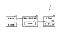
図1に示すように、本実施形態の道路状態判定システム1は、車両100に設けられている。道路状態判定システム1は、道路200上の車線境界線201の状態を判定する状態判定処理を実行する。すなわち、道路状態判定システム1は、車線境界線201を検査する。
<Embodiment>
As shown in FIG. 1, a road state determination system 1 according to the present embodiment is provided in a vehicle 100. The road state determination system 1 executes a state determination process for determining the state of the lane boundary line 201 on the road 200. That is, the road condition determination system 1 inspects the lane boundary line 201.

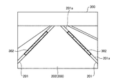
車線境界線201は、道路200の車線202の幅方向の端部に設けられ、車線202に沿って延びている。車線境界線201としては、車線202の左側の端部に設けられた車線境界線201(図4参照)と、車線202の右側の端部に設けられた車線境界線201(図4参照)と、がある。各車線境界線201は、車線202の幅方向に沿って規定の幅を有する。また、車線境界線201には、複数の種類がある。例えば、車線境界線201の形状としては、連続線状(実線状)や破線状がある。破線状の車線境界線201は、車線202の延び方向に互いに間隔を空けて配置された複数の帯状部201a(図5参照)を有する。また、車線境界線201の色としては、白色や黄色がある。車線境界線201は、例えば、道路200上に塗られた塗料によって構成されている。車線境界線201は、車線区画線とも称され得る。   The lane boundary line 201 is provided at the end in the width direction of the lane 202 of the road 200, and extends along the lane 202. The lane boundary line 201 includes a lane boundary line 201 (see FIG. 4) provided at the left end of the lane 202, and a lane boundary line 201 (see FIG. 4) provided at the right end of the lane 202. There is. Each lane boundary line 201 has a predetermined width along the width direction of the lane 202. There are a plurality of types of lane boundary lines 201. For example, the shape of the lane boundary line 201 includes a continuous line shape (solid line shape) and a broken line shape. Dashed lane boundary line 201 has a plurality of strips 201 a (see FIG. 5) that are spaced apart from each other in the direction in which lane 202 extends. Further, the color of the lane boundary line 201 includes white and yellow. The lane boundary line 201 is made of, for example, paint applied on the road 200. Lane boundary line 201 may also be referred to as a lane line.

図2に示すように、道路状態判定システム1は、撮像装置10と、表示装置20と、記憶装置30と、道路状態判定装置40と、を備える。   As illustrated in FIG. 2, the road state determination system 1 includes an imaging device 10, a display device 20, a storage device 30, and a road state determination device 40.

撮像装置10は、例えば、CCD(Charge Coupled Device)やCIS(CMOS Image Sensor)等の撮像素子を有するデジタルカメラである。本実施形態では、一例として、撮像装置10は、車両100の車室内に設けられている(図1参照)。撮像装置10は、フロントガラスとルームミラーとの間に配置されうる。撮像装置10は、車両100の前方の道路200を含む車両100の周辺の外部環境を逐次撮像する。撮像装置10は、道路200を撮像して得た画像300(画像データ、図4〜7参照)を、フレーム単位で出力する。なお、撮像装置10の設置は、車線境界線201を撮像できる位置であればよい。例えば、撮像装置10を、車両100の前部のナンバープレート付近に設置してもよいし、車両100の前部のライト付近に設置してもよいし、サイドミラーに取り付けてもよい。   The imaging device 10 is a digital camera having an imaging element such as a CCD (Charge Coupled Device) or a CIS (CMOS Image Sensor). In the present embodiment, as an example, the imaging device 10 is provided in the passenger compartment of the vehicle 100 (see FIG. 1). The imaging device 10 can be disposed between the windshield and the rearview mirror. The imaging device 10 sequentially captures the external environment around the vehicle 100 including the road 200 in front of the vehicle 100. The imaging device 10 outputs an image 300 (image data, see FIGS. 4 to 7) obtained by imaging the road 200 in units of frames. Note that the imaging device 10 may be installed at any position where the lane boundary line 201 can be imaged. For example, the imaging device 10 may be installed near the license plate at the front of the vehicle 100, may be installed near the light at the front of the vehicle 100, or may be attached to a side mirror.

表示装置20は、例えば、LCD(Liquid Crystal Display)やOELD(Organic Electroluminescent Display)等である。表示装置20は、例えば、車両100の車室に居る乗員が目視可能な位置に配置されている。   The display device 20 is, for example, an LCD (Liquid Crystal Display) or an OELD (Organic Electroluminescent Display). The display device 20 is disposed, for example, at a position where an occupant in the passenger compartment of the vehicle 100 can view.

記憶装置30は、データベース30aを記憶している。データベース30aは、基準画像や状態判定処理での判定結果(検査結果)を含む。基準画像は、車線境界線201が正常な状態の道路200の画像である。判定結果は、過去に状態が判定された車線境界線の判定結果についての情報である。記憶装置30は、記憶部の一例である。   The storage device 30 stores a database 30a. The database 30a includes reference images and determination results (inspection results) in the state determination process. The reference image is an image of the road 200 in which the lane boundary line 201 is normal. The determination result is information about the determination result of the lane boundary line whose state has been determined in the past. The storage device 30 is an example of a storage unit.

図2に示すように、道路状態判定装置40は、処理部41を有する。処理部41は、例えば、CPU(Central Processing Unit)と、記憶部と、を有する。図3に示すように、処理部41内には、画像取得部41a、領域決定部41b、状態判定部41c、および結果出力部41dが実現される。図3に示す処理部41内の各構成は、処理部41のCPUが記憶部に記憶されたプログラムを実行することで実現される。すなわち、プログラムには、図3に示される処理部41の各ブロックに対応したモジュールが含まれる。なお、これらの各部をハードウェアで実現するように構成してもよい。処理部41は、車線境界線201の状態判定処理を実行する。状態判定処理は、車線境界線201の状態の判定を行う処理である。   As illustrated in FIG. 2, the road state determination device 40 includes a processing unit 41. The processing unit 41 includes, for example, a CPU (Central Processing Unit) and a storage unit. As shown in FIG. 3, an image acquisition unit 41a, a region determination unit 41b, a state determination unit 41c, and a result output unit 41d are realized in the processing unit 41. Each component in the processing unit 41 illustrated in FIG. 3 is realized by the CPU of the processing unit 41 executing a program stored in the storage unit. That is, the program includes a module corresponding to each block of the processing unit 41 shown in FIG. In addition, you may comprise so that these each part may be implement | achieved by hardware. The processing unit 41 executes a state determination process for the lane boundary line 201. The state determination process is a process for determining the state of the lane boundary line 201.

画像取得部41aは、道路200が撮像された画像300を撮像装置10から取得する。ここで、図4〜6のそれぞれには、画像300の一例が示されている。図4〜6の各画像300には、道路200に設けられた車線境界線201が含まれている。図4では、左右の車線境界線201が連続線状である道路200の画像300が示され、図5では、左側の車線境界線201が連続線状であり且つ右側の車線境界線201が破線状である道路200の画像300が示されている。また、図6では、車線境界線201を、駐車車両203や水溜まり204が覆った状態の道路200の画像300が示されている。駐車車両203や水溜まり204は、車線境界線201を覆った覆体の一例である。また、画像取得部41aは、取得した画像300を、記憶装置30に送信してデータベース30aに記憶させる。   The image acquisition unit 41 a acquires an image 300 obtained by capturing the road 200 from the imaging device 10. Here, an example of the image 300 is shown in each of FIGS. Each image 300 in FIGS. 4 to 6 includes a lane boundary line 201 provided on the road 200. 4 shows an image 300 of the road 200 in which the left and right lane boundary lines 201 are continuous lines. In FIG. 5, the left lane boundary line 201 is continuous lines and the right lane boundary line 201 is a broken line. An image 300 of a road 200 is shown. Further, FIG. 6 shows an image 300 of the road 200 in a state where the lane boundary line 201 is covered with the parked vehicle 203 and the water pool 204. The parked vehicle 203 and the water reservoir 204 are an example of a cover that covers the lane boundary line 201. The image acquisition unit 41a transmits the acquired image 300 to the storage device 30 and stores it in the database 30a.

領域決定部41bは、実際の道路200の車線境界線201に対応する、画像300の領域302(図7参照)を決定する。領域決定部41bは、境界線検出部41eと、決定部41fと、を有する。   The area determination unit 41 b determines an area 302 (see FIG. 7) of the image 300 corresponding to the lane boundary line 201 of the actual road 200. The area determination unit 41b includes a boundary line detection unit 41e and a determination unit 41f.

境界線検出部41eは、画像300中の車線境界線201の検出を行う(検出処理)。車線境界線201は、画像300中のエッジ情報を算出し、算出したエッジ情報に直線や曲線を当てはめることにより検出してもよいし、予め用意してあるテンプレート画像と画像300とのパターンマッチング処理を行って検出してもよい。また、パターンマッチング処理で車線境界線201を検出する場合、車線境界線201の確信度を算出してもよい。なお、車線境界線201の検出方法は、上記方法に限定されるものではなく、他の公知の方法であってもよい。本実施形態では、画像300中の車線境界線201の検出において、例えば、図7に示すように、画像300中の各車線境界線201のエッジ線301を検出する。エッジ線301は、例えば、車線境界線201のうち車線202の中央部に近い端部(内側の端部)に位置し、車線境界線201に沿って延びる線である。左側の車線境界線201のエッジ線301は、画像300中の座標位置P1と座標位置P2とに亘り、右側の車線境界線201のエッジ線301は、座標位置P3と座標位置P4とに亘っている。また、境界線検出部41eは、車線境界線201の直線の傾きや曲線の曲率、座標、正常部303(ペイント部、図10参照)の幅と、車線境界線201の確からしさを表す信頼度を検出(算出)してもよい。信頼度は、画像300中のエッジ情報から数値として出力され得る。   The boundary line detection unit 41e detects the lane boundary line 201 in the image 300 (detection process). The lane boundary line 201 may be detected by calculating edge information in the image 300 and applying a straight line or a curve to the calculated edge information, or pattern matching processing between a template image prepared in advance and the image 300 May be detected. Further, when the lane boundary line 201 is detected by the pattern matching process, the certainty factor of the lane boundary line 201 may be calculated. In addition, the detection method of the lane boundary line 201 is not limited to the said method, The other well-known method may be used. In the present embodiment, in detecting the lane boundary line 201 in the image 300, for example, as shown in FIG. 7, the edge line 301 of each lane boundary line 201 in the image 300 is detected. The edge line 301 is, for example, a line that extends along the lane boundary line 201 and is located at an end (inner end) near the center of the lane 202 in the lane boundary 201. The edge line 301 of the left lane boundary line 201 spans the coordinate position P1 and the coordinate position P2 in the image 300, and the edge line 301 of the right lane boundary line 201 spans the coordinate position P3 and the coordinate position P4. Yes. Further, the boundary line detection unit 41e is a reliability indicating the slope of the straight line of the lane boundary line 201, the curvature of the curve, the coordinates, the width of the normal part 303 (paint section, see FIG. 10), and the probability of the lane boundary line 201. May be detected (calculated). The reliability can be output as a numerical value from the edge information in the image 300.

また、境界線検出部41eは、車線境界線201の種類を判別する。ここで、例えば、実際の車線境界線201が破線状となっている場合、剥離や汚れ等の異常によって直線状の車線境界線201が破線状となっているのか、正常な形状が破線状なのかは、画像300中の情報だけで正確に判別することが困難な場合がある。そこで、本実施形態では、境界線検出部41eは、画像300に対応する道路200の基準画像に基づいて、車線境界線201の種類(形状の種類)を判別する。基準画像は、データベース30aに記憶されている。境界線検出部41eは、画像300に対応する道路200の基準画像中の車線境界線201が連続線状の場合、検出した車線境界線201は連続線状であると判別する。一方、境界線検出部41eは、画像300に対応する道路200の基準画像中の車線境界線201が破線状の場合、検出した車線境界線201は破線状であると判別する。なお、画像300と当該画像300の基礎画像とは、例えば、それらに付与された位置情報(撮像位置情報)によって対応付けすることができる。位置情報は、例えば、GPS(Global Positioning System)を用いて算出された位置情報であってもよいし、車両100に設けられた車輪速センサの出力値を用いて算出されたものであってもよい。車輪速センサは、車両100の車輪の回転量や単位時間当たりの回転数を検出するセンサである。車輪速センサを用いる場合、例えば、検査対象の道路200上の位置は、基準位置からの距離を車輪速センサの出力値に基づいて算出し、算出した距離に基づいて特定することができる。   Further, the boundary line detection unit 41e determines the type of the lane boundary line 201. Here, for example, when the actual lane boundary line 201 has a broken line shape, whether the straight lane boundary line 201 has a broken line shape due to an abnormality such as peeling or dirt, or the normal shape is a broken line shape. In some cases, it is difficult to accurately determine whether only the information in the image 300 is present. Thus, in the present embodiment, the boundary line detection unit 41e determines the type (shape type) of the lane boundary line 201 based on the reference image of the road 200 corresponding to the image 300. The reference image is stored in the database 30a. When the lane boundary 201 in the reference image of the road 200 corresponding to the image 300 is a continuous line, the boundary detection unit 41e determines that the detected lane boundary 201 is a continuous line. On the other hand, when the lane boundary line 201 in the reference image of the road 200 corresponding to the image 300 has a broken line shape, the boundary line detection unit 41e determines that the detected lane boundary line 201 has a broken line shape. Note that the image 300 and the basic image of the image 300 can be associated with each other by, for example, position information (imaging position information) given thereto. The position information may be, for example, position information calculated using GPS (Global Positioning System), or may be calculated using an output value of a wheel speed sensor provided in the vehicle 100. Good. The wheel speed sensor is a sensor that detects the amount of rotation of the wheel of the vehicle 100 and the number of rotations per unit time. When the wheel speed sensor is used, for example, the position on the road 200 to be inspected can be specified based on the calculated distance by calculating the distance from the reference position based on the output value of the wheel speed sensor.

境界線検出部41eは、上記の各種情報を含む検出結果を決定部41fに出力するとともに、当該検出結果を記憶装置30に出力して、当該検出結果をデータベース30aに蓄積させる。   The boundary detection unit 41e outputs the detection result including the above-described various information to the determination unit 41f, outputs the detection result to the storage device 30, and accumulates the detection result in the database 30a.

図7に示すように、決定部41fは、境界線検出部41eによって検出された車線境界線201に基づいて、領域302を決定する。詳細には、決定部41fは、検出されたエッジ線301に基づいて、領域302を決定する。領域302は、例えば矩形状であり、図7において太線で囲まれた部分である。決定部41fは、エッジ線301から車線202の外側方向に規定の幅を有した部分を領域302とする。具体的には、決定部41fは、エッジ線301と、当該エッジ線301を車線202の外側方向に平行移動させた線と、に囲まれた矩形の部分を、領域302とする。エッジ線301と直交する領域302の幅は、実際の正常な車線境界線201の幅と略同じである。なお、エッジ線301と直交する領域302の幅は、実際の正常な車線境界線201の幅よりも広くてもよい。決定部41fは、境界線検出部41eによる判別結果が連続線状の車線境界線201の場合、エッジ線301に対して一つの領域302を決定する(図7参照)。一方、決定部41fは、境界線検出部41eによる判別結果が破線状の車線境界線201の場合、エッジ線301に対して複数の領域302を決定する(図8参照)。この場合、決定部41fは、基礎画像中の帯状部201aの延び方向での当該帯状部201aの端部の位置を取得し、当該取得した位置に対応する画像300中の位置から、領域302がエッジ線301に沿って延びるようにする。以上のように、決定部41fは、境界線検出部41eによって検出された一本の車線境界線201の全体、すなわち一本のエッジ線301の全体を領域302に含ませてもよいし、境界線検出部41eによって検出された一本の車線境界線201の一部、すなわち一本のエッジ線301の一部だけを領域302に含ませてもよい。また、決定部41fは、境界線検出部41eによって検出された一本の車線境界線201、すなわち一本のエッジ線301に対して一つまたは複数の領域302を決定することができる。   As illustrated in FIG. 7, the determination unit 41 f determines the region 302 based on the lane boundary line 201 detected by the boundary line detection unit 41 e. Specifically, the determination unit 41f determines the region 302 based on the detected edge line 301. The region 302 has a rectangular shape, for example, and is a portion surrounded by a thick line in FIG. The determination unit 41 f sets a portion having a specified width from the edge line 301 to the outside of the lane 202 as the region 302. Specifically, the determination unit 41 f defines a rectangular portion surrounded by the edge line 301 and a line obtained by translating the edge line 301 in the outward direction of the lane 202 as a region 302. The width of the region 302 orthogonal to the edge line 301 is substantially the same as the width of the actual normal lane boundary line 201. Note that the width of the region 302 orthogonal to the edge line 301 may be wider than the width of the actual normal lane boundary line 201. When the determination result by the boundary detection unit 41e is a continuous lane boundary 201, the determination unit 41f determines one region 302 for the edge line 301 (see FIG. 7). On the other hand, the determination part 41f determines the some area | region 302 with respect to the edge line 301, when the determination result by the boundary line detection part 41e is the lane boundary line 201 of a broken line shape (refer FIG. 8). In this case, the determination unit 41f acquires the position of the end of the strip 201a in the extending direction of the strip 201a in the basic image, and the region 302 is determined from the position in the image 300 corresponding to the acquired position. It extends along the edge line 301. As described above, the determination unit 41f may include the entire lane boundary line 201 detected by the boundary line detection unit 41e, that is, the entire edge line 301 in the region 302, Only a part of one lane boundary line 201 detected by the line detection unit 41e, that is, a part of one edge line 301 may be included in the region 302. In addition, the determination unit 41f can determine one or a plurality of regions 302 for one lane boundary line 201 detected by the boundary line detection unit 41e, that is, one edge line 301.

また、図9に示すように、決定部41fは、境界線検出部41eによって車線境界線201が検出されない場合、画像300中の規定の位置を領域302に決定する。この処理は、例えば、車線境界線201上に駐車車両203や水溜まり204等の覆物が存在している場合(図6参照)や撮像時の天候不良の場合等によって、境界線検出部41eによる車線境界線201の検出ができないときに行われる。画像300中の規定の位置は、一例として、車両100の左右の側方に車線境界線201があると仮定した場合の位置である。また、画像300中の規定の位置は、基礎画像中の車線境界線201に対応する画像300中の位置であってもよい。   As illustrated in FIG. 9, the determination unit 41 f determines a predetermined position in the image 300 as the region 302 when the lane boundary line 201 is not detected by the boundary line detection unit 41 e. This process is performed by the boundary detection unit 41e when, for example, there is a cover such as a parked vehicle 203 or a puddle 204 on the lane boundary 201 (see FIG. 6) or when the weather is bad during imaging. This is performed when the lane boundary 201 cannot be detected. The specified position in the image 300 is, for example, a position when it is assumed that the lane boundary line 201 exists on the left and right sides of the vehicle 100. Further, the specified position in the image 300 may be a position in the image 300 corresponding to the lane boundary line 201 in the basic image.

決定部41fは、決定した領域302の座標情報を状態判定部41cに出力する。   The determination unit 41f outputs the coordinate information of the determined region 302 to the state determination unit 41c.

状態判定部41cは、画像300のうち領域302に基づいて、車線境界線201の状態を判定する。状態判定部41cは、情報取得部41gと、判定部41hと、を有する。   The state determination unit 41 c determines the state of the lane boundary line 201 based on the region 302 in the image 300. The state determination unit 41c includes an information acquisition unit 41g and a determination unit 41h.

情報取得部41gは、領域302についての情報を取得する。情報取得部41gは、領域302の色についての情報である色情報、領域302の大きさについての情報である大きさ情報、領域302の明るさについての情報である明るさ情報、および領域302の模様についての情報である模様情報のうち少なくとも一つを取得する。本実施形態では、情報取得部41gは、上記の全ての情報を取得する。   The information acquisition unit 41g acquires information about the area 302. The information acquisition unit 41g includes color information that is information about the color of the region 302, size information that is information about the size of the region 302, brightness information that is information about the brightness of the region 302, and At least one of pattern information that is information about the pattern is acquired. In the present embodiment, the information acquisition unit 41g acquires all the information described above.

情報取得部41gは、上記の情報を得る場合、前処理として、画像300に対して、アフィン変換や、輝度補正、ブロック分割を行う。これらの前処理は、必須ではなく必要に応じて行われる。そして、情報取得部41gは、色情報としての領域302の色相を、領域302において色変換を行って取得する。また、情報取得部41gは、大きさ情報としての領域302の正常部303(ペイント部分)の面積を、領域302において輝度値が規定の値以上の画素の数を計数し当該画素数に基づいて算出する。また、情報取得部41gは、明るさ情報としての領域302の輝度平均値を、領域302に対して輝度平均処理を行って算出する。また、情報取得部41gは、明るさ情報としての領域302の輝度分散値を、画像300に対して輝度分散処理を行って算出する。また、情報取得部41gは、模様情報としての領域302中の輝度値による領域分割数を、領域302にラベリングを行って算出する。ここで、領域302中の領域分割数は、領域302を二値化した場合に領域302中に輝度値の違いによって生じる領域の数である。また、情報取得部41gは、模様情報として領域302のスペクトルを、領域302に対して高速フーリエ変換(FFT)を行って算出する。また、情報取得部41gは、前処理の大きさや取得した情報に基づいて、上記の各情報の順位を計測量信頼度として各情報に付加してもよい。   When obtaining the above information, the information acquisition unit 41g performs affine transformation, luminance correction, and block division on the image 300 as preprocessing. These pretreatments are not essential and are performed as necessary. Then, the information acquisition unit 41g acquires the hue of the area 302 as color information by performing color conversion in the area 302. Further, the information acquisition unit 41g counts the area of the normal portion 303 (paint portion) of the region 302 as the size information, and counts the number of pixels having a luminance value equal to or greater than a predetermined value in the region 302 based on the number of pixels. calculate. The information acquisition unit 41g calculates the luminance average value of the region 302 as brightness information by performing luminance average processing on the region 302. The information acquisition unit 41g calculates the luminance dispersion value of the region 302 as brightness information by performing luminance dispersion processing on the image 300. The information acquisition unit 41g calculates the number of area divisions based on the luminance value in the area 302 as pattern information by labeling the area 302. Here, the number of area divisions in the area 302 is the number of areas generated in the area 302 due to a difference in luminance value when the area 302 is binarized. Further, the information acquisition unit 41g calculates the spectrum of the region 302 as pattern information by performing fast Fourier transform (FFT) on the region 302. In addition, the information acquisition unit 41g may add the rank of each of the above information as the measurement amount reliability to each information based on the size of the preprocessing and the acquired information.

判定部41hは、情報取得部41gによって取得された情報に基づいて車線境界線201の状態を判定する。例えば、判定部41hは、車線境界線201の異常率を算出する。すなわち、判定部41hは、車線境界線201の異常率がいくつであるかを判定する。車線境界線201の異常率は、領域302中の剥離や汚れ等の異常部304(図10,11参照)の割合である。異常率は、一例として、領域302の総面積に対する情報取得部41gによって取得された領域302の正常部303の面積以外の面積の割合で算出される。また、異常率は、情報取得部41gによって取得された領域302の領域分割数を用いて算出されてもよい。なお、異常率の代わりに、領域302中の正常部303の割合を示す正常率を算出してもよい。また、判定部41hは、当該判定部41hによる車線境界線201の状態の今回の判定結果と、記憶装置30に記憶された車線境界線201の状態の前回の判定結果と、に基づいて、車線境界線201の状態の劣化の進行度(進行状態)を算出する。すなわち、判定部41hは、車線境界線201の状態の劣化の進行度がいくつであるかを判定する。詳細には、判定部41hは、領域302の今回の判定の異常率と、当該領域302の記憶装置30に記憶された前回の判定の異常率との差分を、車線境界線201の状態の劣化の進行度として算出する。ここで、図10には、領域302の前回の道路状態判定処理における状態が示され、図11には、当該領域302の今回の道路状態判定処理における状態が示されている。図10,11中の領域302のそれぞれには、正常部303と複数の異常部304とがある。図10,11では、正常部303に、ハッチングが施されている。そして、図11は、図10に対して異常部304Aが生じた状態となっている。この異常部304Aの有無の違いが異常率の差分、すなわち車線境界線201の状態の劣化の進行度として現れる。   The determination unit 41h determines the state of the lane boundary line 201 based on the information acquired by the information acquisition unit 41g. For example, the determination unit 41h calculates the abnormality rate of the lane boundary line 201. That is, the determination unit 41h determines how many abnormality rates of the lane boundary line 201 are. The abnormality rate of the lane boundary line 201 is a ratio of abnormal portions 304 (see FIGS. 10 and 11) such as peeling or dirt in the region 302. As an example, the abnormality rate is calculated by the ratio of the area other than the area of the normal part 303 of the region 302 acquired by the information acquisition unit 41g to the total area of the region 302. The abnormality rate may be calculated using the number of area divisions of the area 302 acquired by the information acquisition unit 41g. Instead of the abnormality rate, a normal rate indicating the ratio of the normal part 303 in the region 302 may be calculated. Further, the determination unit 41h determines the lane based on the current determination result of the state of the lane boundary line 201 by the determination unit 41h and the previous determination result of the state of the lane boundary line 201 stored in the storage device 30. The progress degree (progression state) of the deterioration of the state of the boundary line 201 is calculated. That is, the determination unit 41h determines how many degrees of deterioration of the state of the lane boundary line 201 are. Specifically, the determination unit 41h determines the difference between the abnormality rate of the current determination in the region 302 and the abnormality rate of the previous determination stored in the storage device 30 in the region 302, and the deterioration of the state of the lane boundary line 201. Calculated as the degree of progress. Here, FIG. 10 shows the state of the region 302 in the previous road state determination process, and FIG. 11 shows the state of the region 302 in the current road state determination process. Each region 302 in FIGS. 10 and 11 includes a normal part 303 and a plurality of abnormal parts 304. 10 and 11, the normal part 303 is hatched. FIG. 11 shows a state where an abnormal portion 304A is generated with respect to FIG. This difference in the presence or absence of the abnormal portion 304A appears as a difference in abnormality rate, that is, the degree of progress of deterioration of the state of the lane boundary line 201.

また、判定部41hは、境界線検出部41eによる車線境界線201の検出がされない場合、画像300に基づいて、車線境界線201の状態の判定の可否を判断する。一例として、判定部41hは、画像300と、当該画像300に対応する判定可否判断用画像と、に基づいて、車線境界線201の状態の判定の可否を判断する。判定可否判断用画像は、例えば、画像300に対応する画像であって前回の判定に用いられデータベース30aに記憶された画像や、画像300の基準画像である。ここで、道路200全体の色情報に規定以上の差が有る場合、車線境界線201が検出されない原因は、例えば天候不良や車線境界線201上の覆物等によるものと推測でき、道路200全体の色情報に規定以上の差が無い場合、車線境界線201が検出されない原因は、車線境界線201の異常によるものと推測できる。よって、本実施形態では、判定部41hは、画像300と判定可否判断用画像との色情報の差分をとり、道路200全体の色情報に規定以上の差が有る場合には、車線境界線201の状態の判定は不可であると判断し、道路200全体の色情報に規定以上の差が無い場合には、車線境界線201の状態の判定は可能であると判定する。   In addition, the determination unit 41 h determines whether or not the state of the lane boundary line 201 can be determined based on the image 300 when the lane boundary line 201 is not detected by the boundary line detection unit 41 e. As an example, the determination unit 41h determines whether or not the state of the lane boundary line 201 can be determined based on the image 300 and a determination availability determination image corresponding to the image 300. The determination availability image is, for example, an image corresponding to the image 300 and used for the previous determination and stored in the database 30a, or a reference image of the image 300. Here, when the color information of the entire road 200 has a difference greater than a specified value, the reason why the lane boundary line 201 is not detected can be assumed to be due to, for example, bad weather or a cover on the lane boundary line 201. If there is no difference greater than the specified color information, it can be assumed that the reason why the lane boundary 201 is not detected is due to an abnormality in the lane boundary 201. Therefore, in the present embodiment, the determination unit 41h takes the difference in color information between the image 300 and the determination availability image, and if there is a difference greater than or equal to the standard in the color information of the entire road 200, the lane boundary line 201 It is determined that the state of the lane boundary 201 can be determined when the color information of the entire road 200 is not more than a specified difference.

また、判定部41hは、画像300のうち領域302に基づいて、当該領域302中の車線境界線201の種類を判別する。本実施形態では、判定部41hは、車線境界線201の色の種類を判別する。判定部41hは、情報取得部41gによって取得された領域302の色相によって、車線境界線201の色を判別する。例えば、判定部41hは、白色の色相が領域302の正常部303に全体的に存在する場合は白色の車線境界線201と判定し、黄色(追い越し禁止を示す色)の色情報が領域302の正常部303に全体的に存在している場合は黄色(追い越し禁止)の車線境界線201であると判別する。   In addition, the determination unit 41 h determines the type of the lane boundary line 201 in the region 302 based on the region 302 in the image 300. In the present embodiment, the determination unit 41h determines the color type of the lane boundary line 201. The determination unit 41h determines the color of the lane boundary 201 based on the hue of the area 302 acquired by the information acquisition unit 41g. For example, the determination unit 41 h determines the white lane boundary 201 when the white hue is entirely present in the normal portion 303 of the region 302, and the yellow (color indicating overtaking prohibition) color information is included in the region 302. If it exists in the normal part 303 as a whole, it is determined that the lane boundary line 201 is yellow (passing prohibited).

判定部41hは、上記の判定結果および判別結果を結果出力部41dに出力するとともに、当該判定結果および判別結果を記憶装置30に出力して、当該判定結果をデータベース30aに蓄積させる。すなわち、判定部41hは、車線境界線の状態を記憶する記憶装置30に、判定した車線境界線201の状態を記憶させる。   The determination unit 41h outputs the determination result and the determination result to the result output unit 41d, outputs the determination result and the determination result to the storage device 30, and accumulates the determination result in the database 30a. That is, the determination unit 41h stores the determined state of the lane boundary line 201 in the storage device 30 that stores the state of the lane boundary line.

結果出力部41dは、画像取得部41aによって取得された画像300と、境界線検出部41eによって検出された車線境界線201と、状態判定部41cの判定結果(判別結果)と、を表示装置20に表示させる。   The result output unit 41d displays the image 300 acquired by the image acquisition unit 41a, the lane boundary line 201 detected by the boundary line detection unit 41e, and the determination result (discrimination result) of the state determination unit 41c. To display.

また、本実施形態では、状態判定処理によって取得された各種情報は、データベース30aに蓄積され、当該蓄積された情報が次回の状態判定処理時に参照されて状態判定の精度の向上が図られている。また、処理部41は、状態判定処理における算出値(検出値)のばらつきを統計的に処理したり、駐車車両203によって車線202の状態を把握できなかったときの情報を過去情報から補間して作成することにより、データベース30aを強化してもよい。   In the present embodiment, various types of information acquired by the state determination process are stored in the database 30a, and the stored information is referred to in the next state determination process to improve the accuracy of the state determination. . In addition, the processing unit 41 statistically processes the variation of the calculated value (detected value) in the state determination process, or interpolates information when the parked vehicle 203 cannot grasp the state of the lane 202 from past information. The database 30a may be strengthened by creating it.

次に、以上のように構成された処理部41による道路状態判定処理の手順を図12のフローチャートを参照して説明する。まず、画像取得部41aは、画像300を取得する(S1)。   Next, the procedure of the road state determination process by the processing unit 41 configured as described above will be described with reference to the flowchart of FIG. First, the image acquisition unit 41a acquires the image 300 (S1).

次に、境界線検出部41eは、車線境界線201の検出処理を行う(S2)。境界線検出部41eによって画像300中に車線境界線201のエッジ線301が検出された場合(S3:Yes)、決定部41fは、検出結果としてのエッジ線301に基づいて領域302を決定する(S4)。   Next, the boundary line detection part 41e performs the detection process of the lane boundary line 201 (S2). When the boundary line detection unit 41e detects the edge line 301 of the lane boundary line 201 in the image 300 (S3: Yes), the determination unit 41f determines the region 302 based on the edge line 301 as a detection result ( S4).

次に、情報取得部41gは、領域302の情報として、色情報、大きさ情報、明るさ情報、および模様情報を取得する(S5)。次に、判定部41hは、情報取得部41gによって取得された情報に基づいて車線境界線201の状態を判定する(S6)。次に、結果出力部41dは、判定部41hの判定結果を出力する(S7)。具体的には、判定部41hは、判定部41hの判定結果を表示装置20に表示させる。   Next, the information acquisition unit 41g acquires color information, size information, brightness information, and pattern information as information of the region 302 (S5). Next, the determination unit 41h determines the state of the lane boundary line 201 based on the information acquired by the information acquisition unit 41g (S6). Next, the result output unit 41d outputs the determination result of the determination unit 41h (S7). Specifically, the determination unit 41h causes the display device 20 to display the determination result of the determination unit 41h.

また、境界線検出部41eによって画像300中に車線境界線201のエッジ線301が検出されない場合(S3:No)、決定部41fは、画像300と、画像300に対応する判定可否判断用画像と、に基づいて、車線境界線201の状態の判定(点検)が可能かを判断する(S8)。決定部41fは、車線境界線201の状態の判定は可能であると判断した場合(S8:Yes)、画像300中の規定の位置を領域302に決定する(S9)。この場合、処理部41は、S5に進み、S5以降の処理を行う。   In addition, when the edge line 301 of the lane boundary line 201 is not detected in the image 300 by the boundary line detection unit 41e (S3: No), the determination unit 41f includes the image 300 and the determination availability determination image corresponding to the image 300. Based on the above, it is determined whether the state of the lane boundary line 201 can be determined (inspected) (S8). If the determining unit 41f determines that the state of the lane boundary line 201 can be determined (S8: Yes), the determining unit 41f determines the specified position in the image 300 as the region 302 (S9). In this case, the process part 41 progresses to S5 and performs the process after S5.

一方、決定部41fが車線境界線201の状態の判定は可能でないと判断した場合(S8:No)、処理部41は、S7に進み、S7の処理を行う。この場合、S7で、結果出力部41dは、車線境界線201の状態の判定(点検)が可能でない旨を、表示装置20に表示させる。   On the other hand, when the determination unit 41f determines that the state of the lane boundary line 201 cannot be determined (S8: No), the processing unit 41 proceeds to S7 and performs the processing of S7. In this case, in S7, the result output unit 41d causes the display device 20 to display that the determination (inspection) of the state of the lane boundary line 201 is not possible.

以上、説明したように、本実施形態では、画像取得部41aが、道路200が撮像された画像300を取得し、領域決定部41bが、道路200の車線境界線201に対応する画像300の領域302を決定し、状態判定部41cが、画像300のうち領域302に基づいて、車線境界線201の状態を判定する。よって、領域決定部41bが、道路200の車線境界線201に対応する画像300の領域302を決定するので、例えば、剥離や汚れ等の異常によって車線境界線201の幅が正規の幅でない場合でも、判定対象部をより正確に特定することができる。したがって、車線境界線201の状態をより精度よく判定することができる。   As described above, in the present embodiment, the image acquisition unit 41 a acquires the image 300 obtained by capturing the road 200, and the region determination unit 41 b performs the region of the image 300 corresponding to the lane boundary line 201 of the road 200. 302 is determined, and the state determination unit 41 c determines the state of the lane boundary 201 based on the region 302 in the image 300. Therefore, since the area determination unit 41b determines the area 302 of the image 300 corresponding to the lane boundary line 201 of the road 200, for example, even when the width of the lane boundary line 201 is not a normal width due to an abnormality such as peeling or dirt. The determination target part can be specified more accurately. Therefore, the state of the lane boundary line 201 can be determined with higher accuracy.

また、本実施形態では、画像300に対する画像処理によって車線境界線を検出し、領域302での異常率を算出することで、車線境界線201の異常を全自動で定量的に算出することができる。また、領域302の複数の情報を取得して当該情報に基づいて領域302の状態を判定するので、外乱に強く安定した判定を行うことができる。   Further, in the present embodiment, the lane boundary line is detected by image processing on the image 300, and the abnormality rate in the region 302 is calculated, whereby the abnormality of the lane boundary line 201 can be calculated automatically and quantitatively. . Further, since a plurality of pieces of information on the region 302 are acquired and the state of the region 302 is determined based on the information, it is possible to make a stable determination that is strong against disturbance.

なお、境界線検出部41eは、車線境界線201と一緒に、横断歩道や速度などの路面標示、停止線等を検出してもよい。横断歩道や停止線は、例えば、道路面を二値化して、白色の領域が一定の割合存在する領域として検出することができる。路面標示は、道路上に限定して公知の方法を用いた文字認識によって検出することができる。そして、これらの路面標示および停止線に対しても、状態の判定を行ってもよい。これにより、車線境界線201だけでなく、道路200全体の劣化診断が可能となる。   The boundary line detection unit 41e may detect a road marking such as a pedestrian crossing and a speed, a stop line, and the like together with the lane boundary line 201. For example, a pedestrian crossing or a stop line can be detected as an area where a white area is present in a certain ratio by binarizing the road surface. The road marking can be detected by character recognition using a known method only on the road. And you may determine a state also about these road markings and a stop line. Thereby, not only the lane boundary line 201 but also the entire road 200 can be diagnosed for deterioration.

<第1の変形例>
本変形例では、図13に示すように、決定部41fは、境界線検出部41eによって検出された一本の車線境界線201に対して、車線境界線201の形状に関係無く、複数の領域302を決定する。複数の領域302は、車線境界線201(エッジ線301)の延び方向に沿って並べられる。本実施形態では、各車線境界線201に対して二つの領域302が設けられる。
<First Modification>
In the present modification, as illustrated in FIG. 13, the determination unit 41 f has a plurality of regions for one lane boundary line 201 detected by the boundary line detection unit 41 e regardless of the shape of the lane boundary line 201. 302 is determined. The plurality of regions 302 are arranged along the extending direction of the lane boundary line 201 (edge line 301). In the present embodiment, two regions 302 are provided for each lane boundary line 201.

また、状態判定部41cは、一本の車線境界線201の二つの領域302のうち車両100の進行方向で前方(図13で上側)に位置する領域302に対しては、色情報や明るさ情報に基づいて領域302の状態を判定する。これにより、二つの領域302のうち車両100の進行方向で前方に位置し撮像距離が長くなる領域302、すなわち画素数が少なくなる領域302に対しては、汚れの状態を判定することができる。一方、状態判定部41cは、一本の車線境界線201の二つの領域302のうち車両100の進行方向で後方(図13で下側)に位置する領域302に対しては、大きさ上方や模様上方に基づいて領域302の状態を判定する。これにより、二つの領域302のうち車両100の進行方向で後方に位置し撮像距離が短くなる領域302、すなわち画素数が多くなる領域302に対しては、ひび割れ状態を判定することができる。なお、ある画像300(フレーム)で二つの領域302のうち車両100の進行方向で前方(図13で上側)に位置する領域302が、次に画像300(フレーム)で二つの領域302のうち車両100の進行方向で後方に位置するように、撮像を行ってもよい。これにより、一つの領域302に対する状態の判定を、互いに異なる情報を用いて複数回(二回)行うことができる。   In addition, the state determination unit 41c determines color information and brightness for the region 302 located forward (upward in FIG. 13) in the traveling direction of the vehicle 100 out of the two regions 302 of the single lane boundary line 201. The state of the area 302 is determined based on the information. As a result, the dirt state can be determined for the region 302 that is located forward in the traveling direction of the vehicle 100 and has a long imaging distance, that is, the region 302 in which the number of pixels decreases, of the two regions 302. On the other hand, the state determination unit 41c is larger in size than the region 302 located rearward (downward in FIG. 13) in the traveling direction of the vehicle 100 out of the two regions 302 of one lane boundary line 201. The state of the region 302 is determined based on the pattern upper side. As a result, the cracked state can be determined for the region 302 that is located rearward in the traveling direction of the vehicle 100 and has a short imaging distance, that is, the region 302 that has a large number of pixels. Of the two regions 302 in a certain image 300 (frame), the region 302 positioned forward (upward in FIG. 13) in the traveling direction of the vehicle 100 is the next, and the vehicle in the two regions 302 in the next image 300 (frame). You may image so that it may be located back in the advancing direction of 100. Thereby, the determination of the state for one region 302 can be performed a plurality of times (twice) using different information.

<第2の変形例>
本変形例では、図14に示すように、決定部41fは、境界線検出部41eによって検出された車線境界線201、すなわちエッジ線301の長さよりも領域302の長さを長くする。まず、決定部41fは、境界線検出部41eによって検出されそれぞれ座標位置P1,P3と座標位置P2,P4とに亘る二つのエッジ線301を、線形補間する。詳細には、決定部41fは、エッジ線301をそれぞれ座標位置P1,P3から座標位置P2,P4と反対側の座標位置P5,P6まで延長して、エッジ線301Aを得る。次に、決定部41fは、各エッジ線301Aに対して領域302を決定する。このときの領域302の決定方法は、エッジ線301の場合と同様である。これにより、境界線検出部41eによって検出された車線境界線201(エッジ線301)の長さよりも長い領域302で状態の判定を行うことができる。
<Second Modification>
In the present modification, as illustrated in FIG. 14, the determination unit 41 f makes the length of the region 302 longer than the length of the lane boundary line 201, that is, the edge line 301 detected by the boundary line detection unit 41 e. First, the determination unit 41f linearly interpolates two edge lines 301 that are detected by the boundary line detection unit 41e and span the coordinate positions P1 and P3 and the coordinate positions P2 and P4, respectively. Specifically, the determination unit 41f extends the edge line 301 from the coordinate positions P1 and P3 to the coordinate positions P5 and P6 on the opposite side to the coordinate positions P2 and P4, respectively, and obtains an edge line 301A. Next, the determination unit 41f determines a region 302 for each edge line 301A. The method for determining the region 302 at this time is the same as that for the edge line 301. Thereby, it is possible to determine the state in the region 302 that is longer than the length of the lane boundary line 201 (edge line 301) detected by the boundary line detection unit 41e.

以上、本発明の実施形態および変形例を説明したが、これら実施形態および変形例は、例として提示したものであり、発明の範囲を限定することは意図していない。これら新規な実施形態および変形例は、その他の様々な形態で実施されることが可能であり、発明の要旨を逸脱しない範囲で、種々の省略、置き換え、変更を行うことができる。これら実施形態や変形例は、発明の範囲や要旨に含まれるとともに、特許請求の範囲に記載された発明とその均等の範囲に含まれる。例えば、表示装置20と、記憶装置30と、道路状態判定装置40とは、車両100以外に設置されてもよい。   As mentioned above, although embodiment and the modification of this invention were demonstrated, these embodiment and the modification are shown as an example and are not intending limiting the range of invention. These novel embodiments and modifications can be implemented in various other forms, and various omissions, replacements, and changes can be made without departing from the spirit of the invention. These embodiments and modifications are included in the scope and gist of the invention, and are included in the invention described in the claims and the equivalents thereof. For example, the display device 20, the storage device 30, and the road state determination device 40 may be installed other than the vehicle 100.

30…記憶装置、40…道路状態判定装置、41a…画像取得部、41b…領域決定部、41c…状態判定部、41d…結果出力部、41e…境界線検出部、41f…決定部、41g…情報取得部、41h…判定部、100…車両、200…道路、201…車線境界線、300…画像、301…エッジ線、302…領域。   DESCRIPTION OF SYMBOLS 30 ... Memory | storage device, 40 ... Road state determination apparatus, 41a ... Image acquisition part, 41b ... Area | region determination part, 41c ... State determination part, 41d ... Result output part, 41e ... Boundary line detection part, 41f ... Determination part, 41g ... Information acquisition unit, 41h ... determination unit, 100 ... vehicle, 200 ... road, 201 ... lane boundary line, 300 ... image, 301 ... edge line, 302 ... area.

Claims (14)

道路が撮像された画像を取得する画像取得部と、
前記画像中の車線境界線を検出する境界線検出部と、
前記境界線検出部によって検出された前記車線境界線に基づいて、前記道路の車線境界線に対応する前記画像の領域を決定する領域決定部と、
前記画像のうち前記領域に基づいて、前記車線境界線の状態を判定する状態判定部と、
を備えた道路状態判定装置。
An image acquisition unit that acquires an image of a road imaged;
A boundary detection unit for detecting a lane boundary in the image;
An area determination unit that determines an area of the image corresponding to the lane boundary line of the road based on the lane boundary line detected by the boundary line detection unit;
A state determination unit that determines the state of the lane boundary line based on the region of the image;
A road condition determination device comprising:
前記領域決定部は、前記境界線検出部によって検出された前記車線境界線の長さよりも前記領域の長さを長くする、請求項1に記載の道路状態判定装置。   The road condition determination device according to claim 1, wherein the area determination unit makes the length of the area longer than the length of the lane boundary detected by the boundary detection unit. 前記領域決定部は、前記境界線検出部によって検出された前記車線境界線の全体を前記領域に含ませる、請求項1に記載の道路状態判定装置。   The road state determination device according to claim 1, wherein the area determination unit includes the entire lane boundary line detected by the boundary line detection unit in the area. 前記領域決定部は、前記境界線検出部によって検出された一本の前記車線境界線に対して複数の前記領域を決定する、請求項1に記載の道路状態判定装置。   The road state determination device according to claim 1, wherein the region determination unit determines a plurality of the regions with respect to one lane boundary line detected by the boundary line detection unit. 前記領域決定部は、前記画像に対応する前記道路の基準画像に基づいて前記車線境界線の種類を判別する、請求項1に記載の道路状態判定装置。   The road state determination device according to claim 1, wherein the area determination unit determines a type of the lane boundary line based on a reference image of the road corresponding to the image. 前記状態判定部は、
前記領域の色についての情報、前記領域の大きさについての情報、前記領域の明るさについての情報、および前記領域の模様についての情報のうち少なくとも一つを取得する情報取得部と、
前記情報取得部によって取得された情報に基づいて前記車線境界線の状態を判定する判定部と、
を有した請求項1に記載の道路状態判定装置。
The state determination unit
An information acquisition unit that acquires at least one of information about the color of the region, information about the size of the region, information about the brightness of the region, and information about the pattern of the region;
A determination unit that determines the state of the lane boundary line based on the information acquired by the information acquisition unit;
The road condition determination device according to claim 1, comprising:
前記状態判定部は、前記車線境界線の状態の今回の判定結果と、記憶部に記憶された前記車線境界線の状態の前回の判定結果と、に基づいて、前記車線境界線の状態の劣化の進行度を算出する、請求項1に記載の道路状態判定装置。   The state determination unit is based on the current determination result of the state of the lane boundary line and the previous determination result of the state of the lane boundary line stored in the storage unit, and the deterioration of the state of the lane boundary line The road condition determination device according to claim 1, wherein the degree of progress of the vehicle is calculated. 道路が撮像された画像を取得し、前記画像中の車線境界線を検出し、検出された前記車線境界線に基づいて、前記道路の車線境界線に対応する前記画像の領域を決定し、前記画像のうち前記領域に基づいて、前記車線境界線の状態を判定する、道路状態判定方法。   Acquiring an image of a road imaged, detecting a lane boundary in the image, determining a region of the image corresponding to the lane boundary of the road based on the detected lane boundary; A road state determination method for determining a state of the lane boundary line based on the region in an image. 検出された前記車線境界線の長さよりも前記領域の長さを長くする、請求項8に記載の道路状態判定方法。   The road condition determination method according to claim 8, wherein a length of the area is made longer than a length of the detected lane boundary line. 検出された前記車線境界線の全体を前記領域に含ませる、請求項8に記載の道路状態判定方法。   The road condition determination method according to claim 8, wherein the entire detected lane boundary line is included in the region. 検出された一本の前記車線境界線に対して複数の前記領域を決定する、請求項8に記載の道路状態判定方法。   The road condition determination method according to claim 8, wherein a plurality of the regions are determined for one detected lane boundary line. 前記画像に対応する前記道路の基準画像に基づいて前記車線境界線の種類を判別する、請求項8に記載の道路状態判定方法。   The road condition determination method according to claim 8, wherein a type of the lane boundary line is determined based on a reference image of the road corresponding to the image. 前記領域の色についての情報、前記領域の大きさについての情報、前記領域の明るさについての情報、および前記領域の模様についての情報のうち少なくとも一つを取得し、取得された情報に基づいて前記車線境界線の状態を判定する、請求項8に記載の道路状態判定方法。   Obtain at least one of information about the color of the region, information about the size of the region, information about the brightness of the region, and information about the pattern of the region, and based on the acquired information The road state determination method according to claim 8, wherein the state of the lane boundary line is determined. 前記車線境界線の状態の今回の判定結果と、記憶部に記憶された前記車線境界線の状態の前回の判定結果と、に基づいて、前記車線境界線の状態の劣化の進行度を算出する、請求項8に記載の道路状態判定方法。   Based on the current determination result of the lane boundary line state and the previous determination result of the lane boundary line state stored in the storage unit, the degree of progress of the deterioration of the lane boundary line state is calculated. The road condition determination method according to claim 8.
JP2015051067A 2015-03-13 2015-03-13 Road state determination apparatus and road state determination method Pending JP2016170708A (en)

Priority Applications (1)

Application Number Priority Date Filing Date Title
JP2015051067A JP2016170708A (en) 2015-03-13 2015-03-13 Road state determination apparatus and road state determination method

Applications Claiming Priority (1)

Application Number Priority Date Filing Date Title
JP2015051067A JP2016170708A (en) 2015-03-13 2015-03-13 Road state determination apparatus and road state determination method

Publications (1)

Publication Number Publication Date
JP2016170708A true JP2016170708A (en) 2016-09-23

Family

ID=56983940

Family Applications (1)

Application Number Title Priority Date Filing Date
JP2015051067A Pending JP2016170708A (en) 2015-03-13 2015-03-13 Road state determination apparatus and road state determination method

Country Status (1)

Country Link
JP (1) JP2016170708A (en)

Cited By (8)

* Cited by examiner, † Cited by third party
Publication number Priority date Publication date Assignee Title
WO2018180081A1 (en) * 2017-03-29 2018-10-04 パイオニア株式会社 Deteriorated ground-based object identification device, deteriorated ground-based object identification system, deteriorated ground-based object identification method, deteriorated ground-based object identification program and computer-readable recording medium having deteriorated ground-based object identification program recorded therein
JP2018178549A (en) * 2017-04-14 2018-11-15 宮川興業株式会社 Method for diagnosing road compartment line
JP2019132701A (en) * 2018-01-31 2019-08-08 パイオニア株式会社 Map information creation method
US10546489B2 (en) 2017-06-22 2020-01-28 Kabushiki Kaisha Toshiba Information processing apparatus, information process system, and information process method
US10565876B2 (en) 2018-01-29 2020-02-18 Kabushiki Kaisha Toshiba Information processing apparatus, onboard device, information processing system, and information processing method
JP2020149574A (en) * 2019-03-15 2020-09-17 トヨタ自動車株式会社 Compartment line deterioration specification system and compartment line deterioration specification method
JPWO2019107353A1 (en) * 2017-11-30 2020-12-17 パイオニア株式会社 Data structure of map data
KR102395845B1 (en) * 2020-12-02 2022-05-09 (주)베라시스 Image based Lane State Detection Method

Cited By (12)

* Cited by examiner, † Cited by third party
Publication number Priority date Publication date Assignee Title
WO2018180081A1 (en) * 2017-03-29 2018-10-04 パイオニア株式会社 Deteriorated ground-based object identification device, deteriorated ground-based object identification system, deteriorated ground-based object identification method, deteriorated ground-based object identification program and computer-readable recording medium having deteriorated ground-based object identification program recorded therein
JPWO2018180081A1 (en) * 2017-03-29 2020-05-21 パイオニア株式会社 Degraded feature identifying apparatus, degraded feature identifying method, degraded feature identifying program, and computer-readable recording medium recording the degraded feature identifying program
US11157752B2 (en) 2017-03-29 2021-10-26 Pioneer Corporation Degraded feature identification apparatus, degraded feature identification system, degraded feature identification method, degraded feature identification program, and computer-readable recording medium recording degraded feature identification program
JP2022016460A (en) * 2017-03-29 2022-01-21 パイオニア株式会社 Deteriorated ground object identification device, deteriorated ground object identification system, deteriorated ground object identification method, deteriorated ground object identification program and computer readable recording medium with deteriorated ground object identification program recorded thereon
JP2018178549A (en) * 2017-04-14 2018-11-15 宮川興業株式会社 Method for diagnosing road compartment line
US10546489B2 (en) 2017-06-22 2020-01-28 Kabushiki Kaisha Toshiba Information processing apparatus, information process system, and information process method
JPWO2019107353A1 (en) * 2017-11-30 2020-12-17 パイオニア株式会社 Data structure of map data
US10565876B2 (en) 2018-01-29 2020-02-18 Kabushiki Kaisha Toshiba Information processing apparatus, onboard device, information processing system, and information processing method
JP2019132701A (en) * 2018-01-31 2019-08-08 パイオニア株式会社 Map information creation method
JP2020149574A (en) * 2019-03-15 2020-09-17 トヨタ自動車株式会社 Compartment line deterioration specification system and compartment line deterioration specification method
JP7188203B2 (en) 2019-03-15 2022-12-13 トヨタ自動車株式会社 Lane line deterioration identification system and lane line deterioration identification method
KR102395845B1 (en) * 2020-12-02 2022-05-09 (주)베라시스 Image based Lane State Detection Method

Similar Documents

Publication Publication Date Title
JP2016170708A (en) Road state determination apparatus and road state determination method
CN109740469B (en) Lane line detection method, lane line detection device, computer device, and storage medium
US11688183B2 (en) System and method of determining a curve
US9047518B2 (en) Method for the detection and tracking of lane markings
EP3098753A1 (en) Lane detection
TWI534764B (en) Apparatus and method for vehicle positioning
CN109284674A (en) A kind of method and device of determining lane line
EP2963634B1 (en) Stereo camera device
CN107527006B (en) Method for checking a motor vehicle for medium loss, and motor vehicle and system for carrying out such a method
JP5402828B2 (en) Lane boundary detection device, lane boundary detection program
CN109635737B (en) Auxiliary vehicle navigation positioning method based on road marking line visual identification
WO2006101004A1 (en) Vehicle-use image processing system, vehicle-use image processing method, vehicle-use image processing program, vehicle, and method of formulating vehicle-use image processing system
JP6542539B2 (en) Vehicle accessibility determination device
CN107628032A (en) Automatic Pilot control method, device, vehicle and computer-readable recording medium
JP2011180982A (en) Lane marker detecting apparatus
JP2016004287A (en) Traffic lane boundary line extraction device, traffic line boundary line extraction method and program
JP2008282386A (en) Object detector, object detection method, and object detection program
US10706589B2 (en) Vision system for a motor vehicle and method of controlling a vision system
US9824449B2 (en) Object recognition and pedestrian alert apparatus for a vehicle
JP6564127B2 (en) VISUAL SYSTEM FOR AUTOMOBILE AND METHOD FOR CONTROLLING VISUAL SYSTEM
KR102100047B1 (en) Method for position recognition of vehicle using lane-end-point detection algorithm and method for evaluating performance of the same
US9955136B2 (en) Distance measuring device and vehicle provided therewith
CN103870809A (en) Vehicle detection method and device
WO2014050285A1 (en) Stereo camera device
CN111539279B (en) Road height limit detection method, device, equipment and storage medium

Legal Events

Date Code Title Description
A711 Notification of change in applicant

Free format text: JAPANESE INTERMEDIATE CODE: A712

Effective date: 20170911

A711 Notification of change in applicant

Free format text: JAPANESE INTERMEDIATE CODE: A711

Effective date: 20170912