JP2016168729A - Tank unit and liquid jet system - Google Patents

Tank unit and liquid jet system Download PDF

Info

Publication number
JP2016168729A
JP2016168729A JP2015049557A JP2015049557A JP2016168729A JP 2016168729 A JP2016168729 A JP 2016168729A JP 2015049557 A JP2015049557 A JP 2015049557A JP 2015049557 A JP2015049557 A JP 2015049557A JP 2016168729 A JP2016168729 A JP 2016168729A
Authority
JP
Japan
Prior art keywords
tank
unit
liquid
opening
ink
Prior art date
Legal status (The legal status is an assumption and is not a legal conclusion. Google has not performed a legal analysis and makes no representation as to the accuracy of the status listed.)
Pending
Application number
JP2015049557A
Other languages
Japanese (ja)
Other versions
JP2016168729A5 (en
Inventor
尚己 木村
Naomi Kimura
尚己 木村
金谷 宗秀
Munehide Kanetani
宗秀 金谷
Current Assignee (The listed assignees may be inaccurate. Google has not performed a legal analysis and makes no representation or warranty as to the accuracy of the list.)
Seiko Epson Corp
Original Assignee
Seiko Epson Corp
Priority date (The priority date is an assumption and is not a legal conclusion. Google has not performed a legal analysis and makes no representation as to the accuracy of the date listed.)
Filing date
Publication date
Application filed by Seiko Epson Corp filed Critical Seiko Epson Corp
Priority to JP2015049557A priority Critical patent/JP2016168729A/en
Priority to US14/944,784 priority patent/US9493009B2/en
Priority to CN201510863870.6A priority patent/CN105966074A/en
Publication of JP2016168729A publication Critical patent/JP2016168729A/en
Publication of JP2016168729A5 publication Critical patent/JP2016168729A5/ja
Pending legal-status Critical Current

Links

Images

Classifications

    • BPERFORMING OPERATIONS; TRANSPORTING
    • B41PRINTING; LINING MACHINES; TYPEWRITERS; STAMPS
    • B41JTYPEWRITERS; SELECTIVE PRINTING MECHANISMS, i.e. MECHANISMS PRINTING OTHERWISE THAN FROM A FORME; CORRECTION OF TYPOGRAPHICAL ERRORS
    • B41J2/00Typewriters or selective printing mechanisms characterised by the printing or marking process for which they are designed
    • B41J2/005Typewriters or selective printing mechanisms characterised by the printing or marking process for which they are designed characterised by bringing liquid or particles selectively into contact with a printing material
    • B41J2/01Ink jet
    • B41J2/17Ink jet characterised by ink handling
    • B41J2/175Ink supply systems ; Circuit parts therefor
    • B41J2/17503Ink cartridges
    • B41J2/17526Electrical contacts to the cartridge
    • BPERFORMING OPERATIONS; TRANSPORTING
    • B41PRINTING; LINING MACHINES; TYPEWRITERS; STAMPS
    • B41JTYPEWRITERS; SELECTIVE PRINTING MECHANISMS, i.e. MECHANISMS PRINTING OTHERWISE THAN FROM A FORME; CORRECTION OF TYPOGRAPHICAL ERRORS
    • B41J2/00Typewriters or selective printing mechanisms characterised by the printing or marking process for which they are designed
    • B41J2/005Typewriters or selective printing mechanisms characterised by the printing or marking process for which they are designed characterised by bringing liquid or particles selectively into contact with a printing material
    • B41J2/01Ink jet
    • B41J2/17Ink jet characterised by ink handling
    • B41J2/175Ink supply systems ; Circuit parts therefor
    • B41J2/17503Ink cartridges
    • B41J2/17553Outer structure
    • BPERFORMING OPERATIONS; TRANSPORTING
    • B41PRINTING; LINING MACHINES; TYPEWRITERS; STAMPS
    • B41JTYPEWRITERS; SELECTIVE PRINTING MECHANISMS, i.e. MECHANISMS PRINTING OTHERWISE THAN FROM A FORME; CORRECTION OF TYPOGRAPHICAL ERRORS
    • B41J2/00Typewriters or selective printing mechanisms characterised by the printing or marking process for which they are designed
    • B41J2/005Typewriters or selective printing mechanisms characterised by the printing or marking process for which they are designed characterised by bringing liquid or particles selectively into contact with a printing material
    • B41J2/01Ink jet
    • B41J2/17Ink jet characterised by ink handling
    • B41J2/175Ink supply systems ; Circuit parts therefor
    • B41J2/17503Ink cartridges
    • B41J2/17506Refilling of the cartridge
    • B41J2/17509Whilst mounted in the printer
    • BPERFORMING OPERATIONS; TRANSPORTING
    • B41PRINTING; LINING MACHINES; TYPEWRITERS; STAMPS
    • B41JTYPEWRITERS; SELECTIVE PRINTING MECHANISMS, i.e. MECHANISMS PRINTING OTHERWISE THAN FROM A FORME; CORRECTION OF TYPOGRAPHICAL ERRORS
    • B41J2/00Typewriters or selective printing mechanisms characterised by the printing or marking process for which they are designed
    • B41J2/005Typewriters or selective printing mechanisms characterised by the printing or marking process for which they are designed characterised by bringing liquid or particles selectively into contact with a printing material
    • B41J2/01Ink jet
    • B41J2/17Ink jet characterised by ink handling
    • B41J2/175Ink supply systems ; Circuit parts therefor
    • B41J2/17503Ink cartridges
    • B41J2/1752Mounting within the printer
    • BPERFORMING OPERATIONS; TRANSPORTING
    • B41PRINTING; LINING MACHINES; TYPEWRITERS; STAMPS
    • B41JTYPEWRITERS; SELECTIVE PRINTING MECHANISMS, i.e. MECHANISMS PRINTING OTHERWISE THAN FROM A FORME; CORRECTION OF TYPOGRAPHICAL ERRORS
    • B41J2/00Typewriters or selective printing mechanisms characterised by the printing or marking process for which they are designed
    • B41J2/005Typewriters or selective printing mechanisms characterised by the printing or marking process for which they are designed characterised by bringing liquid or particles selectively into contact with a printing material
    • B41J2/01Ink jet
    • B41J2/17Ink jet characterised by ink handling
    • B41J2/175Ink supply systems ; Circuit parts therefor
    • B41J2/17566Ink level or ink residue control
    • BPERFORMING OPERATIONS; TRANSPORTING
    • B41PRINTING; LINING MACHINES; TYPEWRITERS; STAMPS
    • B41JTYPEWRITERS; SELECTIVE PRINTING MECHANISMS, i.e. MECHANISMS PRINTING OTHERWISE THAN FROM A FORME; CORRECTION OF TYPOGRAPHICAL ERRORS
    • B41J29/00Details of, or accessories for, typewriters or selective printing mechanisms not otherwise provided for
    • B41J29/12Guards, shields or dust excluders
    • B41J29/13Cases or covers
    • BPERFORMING OPERATIONS; TRANSPORTING
    • B41PRINTING; LINING MACHINES; TYPEWRITERS; STAMPS
    • B41JTYPEWRITERS; SELECTIVE PRINTING MECHANISMS, i.e. MECHANISMS PRINTING OTHERWISE THAN FROM A FORME; CORRECTION OF TYPOGRAPHICAL ERRORS
    • B41J2/00Typewriters or selective printing mechanisms characterised by the printing or marking process for which they are designed
    • B41J2/005Typewriters or selective printing mechanisms characterised by the printing or marking process for which they are designed characterised by bringing liquid or particles selectively into contact with a printing material
    • B41J2/01Ink jet
    • B41J2/17Ink jet characterised by ink handling
    • B41J2/175Ink supply systems ; Circuit parts therefor
    • B41J2/17566Ink level or ink residue control
    • B41J2002/17579Measuring electrical impedance for ink level indication

Landscapes

  • Ink Jet (AREA)

Abstract

PROBLEM TO BE SOLVED: To provide a technology that enables inspection of a tank to be easily performed.SOLUTION: A tank unit 20A includes: a plurality of ink tanks 25A; a substrate part 80; and a casing part 21A. Each ink tank 25A includes electrode pins 70a, 70b used for detection of an ink IN. The substrate part 80 is connected to rear end parts 72a, 72b of the electrode pins 70a, 70b protruding to the outside of the ink tanks 25A. The casing part 21A houses the ink tanks 25A and the substrate part 80. A through window 92 exposing the electrode pins 70a, 70b to the outside is provided on a back surface of the casing part 21A.SELECTED DRAWING: Figure 3

Description

本発明は、タンクユニットおよび液体噴射システムに関する。   The present invention relates to a tank unit and a liquid ejection system.

液体噴射システムの一態様としては、インク滴を吐出して画像を形成するインクジェットプリンターが知られている。インクジェットプリンターには、複数のインクタンクを備えるタンクユニットが連結されるものがある(例えば、下記特許文献1)。また、インクタンクには、ユーザーによるインクの補充が可能なものや、インクタンク内のインクの有無を電気的に検出可能なものがある(例えば、下記特許文献2)。   As one aspect of the liquid ejecting system, an ink jet printer that forms an image by ejecting ink droplets is known. Some inkjet printers are connected to a tank unit including a plurality of ink tanks (for example, Patent Document 1 below). Some ink tanks can be refilled by the user, and others can electrically detect the presence or absence of ink in the ink tank (for example, Patent Document 2 below).

特開2012−051327号公報JP 2012-051327 A 特開2014−184594号公報JP 2014-184594 A

インクタンクにおいては、工場からの出荷前やメンテナンス時などに、外部との電気的な接続のための端子部に対する電気的導通性の検査やインクの供給性能に関する検査などがおこなわれる場合がある。タンクユニットにおいては、インクタンクに対するそうした検査が簡易におこなえることが望ましい。   In the ink tank, an inspection of electrical continuity with respect to a terminal portion for electrical connection to the outside or an inspection regarding ink supply performance may be performed before shipment from a factory or during maintenance. In the tank unit, it is desirable that such an inspection for the ink tank can be easily performed.

本発明は、少なくとも、液体噴射装置に液体を供給可能なタンクユニットにおける上述の課題を解決するためになされたものであり、以下の形態として実現することが可能である。   SUMMARY An advantage of some aspects of the invention is to solve the above-described problem in a tank unit capable of supplying liquid to a liquid ejecting apparatus, and the invention can be implemented as the following forms.

[1]本発明の第1形態によれば、タンクユニットが提供される。この形態のタンクユニットは、液体を液体噴射装置に供給可能であって良い。前記タンクユニットは、タンクと、外装部と、を備えて良い。前記タンクは、液体収容部と、端子部と、を有して良い。前記液体収容部は、液体を収容可能であって良い。前記端子部は、外部と電気的に接続可能であって良い。前記外装部は、前記タンクを収容可能であるとともに、前記液体噴射装置に連結可能であって良い。前記外装部には、前記タンクにおける前記端子部の少なくとも一部を外部に露出させる1または複数の開口が設けられて良い。前記外装部は、前記開口が前記液体噴射装置に向く姿勢において、前記液体噴射装置に連結されて良い。この形態のタンクユニットによれば、液体噴射装置との連結が解除されているときに、外装部の開口を介して、タンクの端子部に対する検査を容易におこなうことができる。 [1] According to the first embodiment of the present invention, a tank unit is provided. The tank unit of this form may be able to supply liquid to the liquid ejecting apparatus. The tank unit may include a tank and an exterior part. The tank may include a liquid storage portion and a terminal portion. The liquid storage portion may be capable of storing a liquid. The terminal portion may be electrically connectable to the outside. The exterior portion can accommodate the tank and can be coupled to the liquid ejecting apparatus. The exterior portion may be provided with one or a plurality of openings for exposing at least a part of the terminal portion of the tank to the outside. The exterior portion may be coupled to the liquid ejecting apparatus in a posture in which the opening faces the liquid ejecting apparatus. According to the tank unit of this embodiment, when the connection with the liquid ejecting apparatus is released, it is possible to easily inspect the terminal portion of the tank through the opening of the exterior portion.

[2]本発明の第2形態によれば、タンクユニットが提供される。この形態のタンクユニットは、液体を液体噴射装置に供給可能であって良い。前記タンクユニットは、タンクと、外装部と、支持部材と、を備えて良い。前記タンクは、液体収容部と、端子部と、を有して良い。前記液体収容部は、液体を収容可能であって良い。前記端子部は、外部と電気的に接続可能であって良い。前記支持部材は、前記外装部内において、前記タンクを前記外装部に固定可能であって良い。前記支持部材には、前記外装部が前記液体噴射装置に連結されているときに、前記端子部と前記液体噴射装置との間に位置する1または複数の開口が設けられて良い。前記端子部の少なくとも一部は、前記外装部が前記液体噴射装置に連結されていないときに、前記支持部材の前記開口を介して外部に露出して良い。この形態のタンクユニットによれば、液体噴射装置との連結が解除されているときに、支持部材の開口を介して、タンクの端子部に対する検査を容易におこなうことができる。 [2] According to the second embodiment of the present invention, a tank unit is provided. The tank unit of this form may be able to supply liquid to the liquid ejecting apparatus. The tank unit may include a tank, an exterior part, and a support member. The tank may include a liquid storage portion and a terminal portion. The liquid storage portion may be capable of storing a liquid. The terminal portion may be electrically connectable to the outside. The support member may be capable of fixing the tank to the exterior part in the exterior part. The support member may be provided with one or a plurality of openings positioned between the terminal portion and the liquid ejecting apparatus when the exterior portion is connected to the liquid ejecting apparatus. At least a part of the terminal portion may be exposed to the outside through the opening of the support member when the exterior portion is not connected to the liquid ejecting apparatus. According to the tank unit of this embodiment, when the connection with the liquid ejecting apparatus is released, the tank terminal portion can be easily inspected through the opening of the support member.

[3]上記形態のタンクユニットにおいて、前記端子部の少なくとも一部は、前記開口を開口方向に見たときに、前記開口内に位置して良い。この形態のタンクユニットによれば、開口を介した端子部に対するアクセスが容易になり、端子部に対する検査をさらに簡易におこなうことができる。 [3] In the tank unit of the above aspect, at least a part of the terminal portion may be located in the opening when the opening is viewed in the opening direction. According to the tank unit of this form, the access to the terminal portion through the opening is facilitated, and the inspection of the terminal portion can be further simplified.

[4]上記形態のタンクユニットにおいて、前記タンクは、前記液体収容部に収容されている前記液体の検出に用いられる電極部を有し、前記端子部は、前記電極部に電気的に導通して良い。この形態のタンクユニットによれば、液体の検出に用いられる電極の検査を簡易におこなうことができる。 [4] In the tank unit of the above aspect, the tank includes an electrode unit used for detecting the liquid stored in the liquid storage unit, and the terminal unit is electrically connected to the electrode unit. Good. According to the tank unit of this form, it is possible to easily inspect the electrodes used for detecting the liquid.

[5]上記形態のタンクユニットにおいて、前記タンクは、さらに、前記液体収容部に大気を導入可能な大気取入部を備え、前記大気取入部は、前記開口から外部に露出するとともに、前記開口に向かって開口して良い。この形態のタンクユニットによれば、大気取入部を利用する検査を容易におこなうことができる。 [5] In the tank unit of the above aspect, the tank further includes an air intake portion capable of introducing air into the liquid storage portion, and the air intake portion is exposed to the outside from the opening and is disposed in the opening. You can open it. According to the tank unit of this form, it is possible to easily perform an inspection using the air intake unit.

[6]上記形態のタンクユニットにおいて、前記タンクは、さらに、外部から前記液体収容部に前記液体を注入可能な液体注入部を含み、前記開口から露出している前記端子部の少なくとも一部と前記大気取入部とは、前記外装部が前記液体噴射装置に連結されているときに、前記液体収容部の上方の位置であって、前記液体注入部より前記液体噴射装置に近い位置に位置して良い。この形態のタンクユニットによれば、端子部および大気取入部に対する検査が容易化される。 [6] In the tank unit of the above aspect, the tank further includes a liquid injection part capable of injecting the liquid from the outside into the liquid storage part, and at least a part of the terminal part exposed from the opening; The atmosphere intake unit is a position above the liquid storage unit and closer to the liquid ejecting apparatus than the liquid injecting unit when the exterior unit is connected to the liquid ejecting apparatus. Good. According to the tank unit of this form, the inspection of the terminal portion and the air intake portion is facilitated.

[7]上記形態のタンクユニットにおいて、前記タンクは、さらに、外部から前記液体収容部に前記液体を注入可能な液体注入部を含み、前記開口から露出している前記端子部の少なくとも一部と前記大気取入部とは、前記外装部が前記液体噴射装置に連結されているときに、前記液体注入部より上方の位置であって、前記液体注入部より前記液体噴射装置に近い位置に位置して良い。この形態のタンクユニットによれば、端子部および大気取入部に、液体注入部から誤ってこぼれ落ちるなどした液体が付着してしまうことが抑制される。 [7] In the tank unit of the above aspect, the tank further includes a liquid injection portion capable of injecting the liquid from the outside into the liquid storage portion, and at least a part of the terminal portion exposed from the opening; The air intake portion is located above the liquid injection portion and closer to the liquid injection device than the liquid injection portion when the exterior portion is connected to the liquid injection device. Good. According to the tank unit of this form, it is possible to suppress the liquid that has been accidentally spilled from the liquid injecting portion from adhering to the terminal portion and the air intake portion.

[8]上記形態のタンクユニットは、さらに、前記開口を封止可能な封止部材を備えて良い。この形態のタンクユニットによれば、開口を介した端子部への異物の付着などが抑制され、端子部の保護性が高められる。 [8] The tank unit of the above aspect may further include a sealing member capable of sealing the opening. According to the tank unit of this form, the adhesion of foreign matter to the terminal part through the opening is suppressed, and the protection of the terminal part is enhanced.

[9]上記形態のタンクユニットにおいて、前記タンクは、第1液体を収容可能な前記液体収容部である第1液体収容部と、前記端子部である第1端子部と、を有する第1タンクであり、前記タンクユニットは、第2液体を収容可能な第2液体収容部と、外部と電気的に接続可能な第2端子部と、を有する第2タンクをさらに備え、前記2タンクにおける前記2端子部の少なくとも一部は、前記開口を介して、外部に露出して良い。この形態のタンクユニットによれば、外装部に収容されている状態の第1タンクおよび第2タンクの端子部に対する検査を容易におこなうことができる。 [9] In the tank unit of the above aspect, the tank includes a first liquid storage portion that is the liquid storage portion that can store a first liquid, and a first terminal portion that is the terminal portion. The tank unit further includes a second tank having a second liquid storage portion capable of storing a second liquid and a second terminal portion electrically connectable to the outside, and the tank unit includes the second tank. At least a part of the two terminal portions may be exposed to the outside through the opening. According to the tank unit of this form, it is possible to easily inspect the terminal portions of the first tank and the second tank that are accommodated in the exterior portion.

[10]上記形態のタンクユニットにおいて、前記第1タンクは、前記第1液体収容部に大気を導入可能な第1大気取入部を備え、前記第2タンクは、前記第2液体収容部に大気を導入可能な大気取入部を備え、前記第1大気取入部および前記第2大気取入部は、前記開口から外部に露出するとともに、前記開口に向かって開口して良い。この形態のタンクユニットによれば、第2タンクの大気取入部を利用する検査が容易化される。 [10] In the tank unit of the above aspect, the first tank includes a first atmosphere intake unit capable of introducing the atmosphere into the first liquid storage unit, and the second tank includes an atmosphere in the second liquid storage unit. The first air intake portion and the second air intake portion may be exposed to the outside from the opening and open toward the opening. According to the tank unit of this form, the inspection using the air intake part of the second tank is facilitated.

[11]上記形態のタンクユニットにおいて、前記タンクは、第1液体を収容可能な前記液体収容部である第1液体収容部と、前記端子部である第1端子部と、を有する第1タンクであり、前記タンクユニットは、第2液体を収容可能な第2液体収容部と、外部と電気的に接続可能な第2端子部と、を有する第2タンクをさらに備え、前記外装部における前記開口は、前記第1端子部の少なくとも一部を外部に露出させる第1開口と、前記第2端子部の少なくとも一部を外部に露出させる第2開口と、を含んで良い。この形態のタンクユニットによれば、外装部に収容されている状態の第1タンクおよび第2タンクの端子部に対する検査を容易におこなうことができる。 [11] In the tank unit of the above aspect, the tank includes a first liquid storage portion that is the liquid storage portion capable of storing a first liquid, and a first terminal portion that is the terminal portion. The tank unit further includes a second tank having a second liquid storage portion capable of storing a second liquid and a second terminal portion electrically connectable to the outside, and the tank unit includes the second tank. The opening may include a first opening that exposes at least a portion of the first terminal portion to the outside, and a second opening that exposes at least a portion of the second terminal portion to the outside. According to the tank unit of this form, it is possible to easily inspect the terminal portions of the first tank and the second tank that are accommodated in the exterior portion.

[12]上記形態のタンクユニットにおいて、前記タンクは、第1液体を収容可能な前記液体収容部である第1液体収容部と、前記端子部である第1端子部と、を有する第1タンクであり、前記タンクユニットは、第2液体を収容可能な第2液体収容部と、外部と電気的に接続可能な第2端子部と、を有する第2タンクをさらに備え、前記支持部材は、前記第1タンクと前記第2タンクとを前記外装部に固定し、前記支持部材における前記開口は、前記第1端子部の少なくとも一部を外部に露出させる第1開口と、前記第2端子部の少なくとも一部を外部に露出させる第2開口と、を含んで良い。この形態のタンクユニットによれば、第1タンクおよび第2タンクの端子部に対する検査を容易におこなうことができる。 [12] In the tank unit of the above aspect, the tank includes a first liquid storage portion that is the liquid storage portion capable of storing a first liquid, and a first terminal portion that is the terminal portion. The tank unit further includes a second tank having a second liquid storage portion capable of storing a second liquid and a second terminal portion electrically connectable to the outside, and the support member includes: The first tank and the second tank are fixed to the exterior portion, and the opening in the support member is a first opening that exposes at least a part of the first terminal portion to the outside, and the second terminal portion. And a second opening that exposes at least a part of the second portion to the outside. According to the tank unit of this embodiment, it is possible to easily inspect the terminal portions of the first tank and the second tank.

[13]上記形態のタンクユニットにおいて、前記第1タンクは、前記第1液体収容部に大気を導入可能な第1大気取入部を備え、前記第2タンクは、前記第2液体収容部に大気を導入可能な第2大気取入部を備え、前記第1大気取入部は、前記第1開口から外部に露出するとともに、前記第1開口に向かって開口しており、前記第2大気取入部は、前記第2開口から外部に露出するとともに、前記第2開口に向かって開口していて良い。この形態のタンクユニットによれば、第1タンクおよび第2タンクの大気取入部に対する検査が容易化される。 [13] In the tank unit of the above aspect, the first tank includes a first atmosphere intake unit capable of introducing the atmosphere into the first liquid storage unit, and the second tank includes an atmosphere in the second liquid storage unit. The first atmospheric intake portion is exposed to the outside from the first opening and opens toward the first opening, and the second atmospheric intake portion is The second opening may be exposed to the outside and may be open toward the second opening. According to this type of tank unit, the inspection of the air intake portions of the first tank and the second tank is facilitated.

[14]本発明の第3形態によれば、液体噴射システムが提供される。この液体噴射システムは、タンクユニットと、液体噴射装置と、チューブと、を備えて良い。前記タンクユニットは、上記形態のいずれかのタンクユニットであって良い。前記液体噴射装置は、液体噴射ヘッドを有して良い。前記チューブは、前記タンクユニットと前記液体噴射ヘッドとの間において前記液体を流通させて良い。この形態の液体噴射システムによれば、タンクに設けられている端子部に対する検査が容易化される。 [14] According to the third aspect of the present invention, a liquid ejecting system is provided. The liquid ejecting system may include a tank unit, a liquid ejecting apparatus, and a tube. The tank unit may be any tank unit of the above form. The liquid ejecting apparatus may include a liquid ejecting head. The tube may circulate the liquid between the tank unit and the liquid jet head. According to the liquid ejecting system of this aspect, the inspection of the terminal portion provided in the tank is facilitated.

[15]本発明の第4形態によれば、タンクユニットが提供される。このタンクユニットは、液体を液体噴射装置に供給可能であって良い。前記タンクユニットは、タンクと、外装部と、支持部材と、を備えて良い。前記タンクは、液体収容部と、端子部と、を備えて良い。前記液体収容部は、液体を収容可能であって良い。前記端子部は、外部と電気的に接続可能であって良い。前記外装部は、前記タンクを収容可能であって良い。前記支持部材は、前記外装部内において、前記タンクを前記外装部に固定して良い。前記外装部は、前記支持部材の少なくとも一部と、前記タンクの少なくとも一部と、を外部に露出させる開口を有して良い。前記支持部材には、前記外装部における前記開口から露出する部位に、前記端子部の少なくとも一部を外部に露出させる開口が設けられて良い。この形態のタンクユニットによれば、外装部の開口と、支持部材の開口と、を介して、端子部の検査を簡易におこなうことができる。 [15] According to the fourth aspect of the present invention, a tank unit is provided. The tank unit may be capable of supplying liquid to the liquid ejecting apparatus. The tank unit may include a tank, an exterior part, and a support member. The tank may include a liquid storage portion and a terminal portion. The liquid storage portion may be capable of storing a liquid. The terminal portion may be electrically connectable to the outside. The exterior part may be capable of accommodating the tank. The support member may fix the tank to the exterior part in the exterior part. The exterior part may have an opening that exposes at least a part of the support member and at least a part of the tank to the outside. The support member may be provided with an opening that exposes at least a part of the terminal portion to the outside at a portion exposed from the opening in the exterior portion. According to the tank unit of this embodiment, the terminal portion can be easily inspected via the opening of the exterior portion and the opening of the support member.

上述した本発明の各形態の有する複数の構成要素はすべてが必須のものではなく、上述の課題の一部又は全部を解決するため、あるいは、本明細書に記載された効果の一部又は全部を達成するために、適宜、前記複数の構成要素の一部の構成要素について、その変更、削除、新たな他の構成要素との差し替え、限定内容の一部削除を行うことが可能である。また、上述の課題の一部又は全部を解決するため、あるいは、本明細書に記載された効果の一部又は全部を達成するために、上述した本発明の一形態に含まれる技術的特徴の一部又は全部を上述した本発明の他の形態に含まれる技術的特徴の一部又は全部と組み合わせて、本発明の独立した一形態とすることも可能である。   A plurality of constituent elements of each aspect of the present invention described above are not indispensable, and some or all of the effects described in the present specification are to be solved to solve part or all of the above-described problems. In order to achieve the above, it is possible to appropriately change, delete, replace with another new component, and partially delete the limited contents of some of the plurality of components. In order to solve part or all of the above-described problems or to achieve part or all of the effects described in this specification, technical features included in one embodiment of the present invention described above. A part or all of the technical features included in the other aspects of the present invention described above may be combined to form an independent form of the present invention.

本発明は、液体噴射装置に液体を供給可能なタンクユニットや液体噴射システム以外の種々の形態で実現することも可能である。例えば、タンクユニットや液体噴射システムが備えるタンクに対する検査方法や、タンクの検査装置などの形態として実現することもできる。その他に、液体噴射装置以外の液体を消費する液体消費装置に液体を供給可能なタンクユニットや、液体を消費する液体消費システム、それらが備えるタンクに対する検査方法、それらが備えるタンクの検査装置としても実現することもできる。なお、本明細書において「システム」とは、一以上の機能を実現するために、複数の構成要素が、それぞれの機能が直接的または間接的に連関し合うように、一体的、あるいは、分散した状態で、複合的に組み合わされている集合を意味している。従って、本明細書におけるシステムには、複数の構成要素が一体的に組み合わされている「装置」も含まれる。   The present invention can also be realized in various forms other than a tank unit and a liquid ejecting system that can supply liquid to the liquid ejecting apparatus. For example, the present invention can be realized in the form of an inspection method for a tank included in a tank unit or a liquid ejection system, a tank inspection device, or the like. In addition, as a tank unit that can supply liquid to a liquid consuming device that consumes liquid other than the liquid ejecting device, a liquid consuming system that consumes liquid, an inspection method for the tank provided in them, and an inspection device for the tank provided in them It can also be realized. In this specification, “system” means that a plurality of components are integrated or distributed so that each function is directly or indirectly associated with each other in order to realize one or more functions. In this state, it means a set that is combined. Accordingly, the system in this specification also includes an “apparatus” in which a plurality of components are combined together.

第1実施形態におけるインクジェットプリンターの構成を示す概略図。Schematic which shows the structure of the inkjet printer in 1st Embodiment. 第1実施形態におけるインクタンクの外観構成を示す概略斜視図。FIG. 2 is a schematic perspective view illustrating an external configuration of an ink tank according to the first embodiment. 第1実施形態におけるタンクユニットの内部構成を示す概略断面図。The schematic sectional drawing which shows the internal structure of the tank unit in 1st Embodiment. 第1実施形態におけるタンクユニットの背面の一部を示す概略図。Schematic which shows a part of back surface of the tank unit in 1st Embodiment. 第1実施形態における検査装置の構成を示す概略図。Schematic which shows the structure of the test | inspection apparatus in 1st Embodiment. 第1実施形態の検査装置によって検査しているときの状態を示す模式図。The schematic diagram which shows a state when test | inspecting with the test | inspection apparatus of 1st Embodiment. 第2実施形態におけるタンクユニットの構成を示す概略図。Schematic which shows the structure of the tank unit in 2nd Embodiment. 第3実施形態におけるインクタンクの構成を示す概略斜視図。FIG. 10 is a schematic perspective view illustrating a configuration of an ink tank according to a third embodiment. 第3実施形態のタンクユニットの背面の一部を示す概略図。Schematic which shows a part of back surface of the tank unit of 3rd Embodiment. 第4実施形態におけるインクタンクの外観構成を示す概略斜視図。FIG. 10 is a schematic perspective view illustrating an external configuration of an ink tank according to a fourth embodiment. 第4実施形態におけるタンクユニットの内部構成を示す概略断面図。The schematic sectional drawing which shows the internal structure of the tank unit in 4th Embodiment. 第4実施形態におけるタンクユニットの背面の一部を示す概略図。Schematic which shows a part of back surface of the tank unit in 4th Embodiment. 第4実施形態における検査装置の構成を示す概略図。Schematic which shows the structure of the test | inspection apparatus in 4th Embodiment. 第4実施形態の検査装置によって検査しているときの状態を示す模式図。The schematic diagram which shows a state when test | inspecting with the test | inspection apparatus of 4th Embodiment. 第5実施形態におけるタンクユニットの構成を示す概略図。Schematic which shows the structure of the tank unit in 5th Embodiment. 第6実施形態におけるタンクユニットの構成を示す概略断面図。The schematic sectional drawing which shows the structure of the tank unit in 6th Embodiment. 第6実施形態における封止部材の他の構成例を示す概略断面図。The schematic sectional drawing which shows the other structural example of the sealing member in 6th Embodiment. 第6実施形態における封止部材の他の構成例を示す概略断面図。The schematic sectional drawing which shows the other structural example of the sealing member in 6th Embodiment. 第7実施形態におけるプリンターの構成の一部を示す概略斜視図。FIG. 10 is a schematic perspective view illustrating a part of the configuration of a printer according to a seventh embodiment. 第7実施形態におけるタンクユニットを示す概略斜視図。The schematic perspective view which shows the tank unit in 7th Embodiment. 第7実施形態におけるタンクユニットの背面側を示す概略斜視図。The schematic perspective view which shows the back side of the tank unit in 7th Embodiment. 第7実施形態におけるインクタンクの概略側面図。The schematic side view of the ink tank in 7th Embodiment. 第7実施形態におけるインクタンクに回路ユニットが取り付けられている状態を示す概略斜視図。FIG. 10 is a schematic perspective view illustrating a state where a circuit unit is attached to an ink tank according to a seventh embodiment. 第7実施形態におけるインクタンクおよび回路ユニットの概略分解斜視図。FIG. 10 is a schematic exploded perspective view of an ink tank and a circuit unit in a seventh embodiment. 第7実施形態におけるタンクユニットの背面の一部を示す概略背面図。The schematic rear view which shows a part of back surface of the tank unit in 7th Embodiment. 第7実施形態におけるタンクユニットの概略断面図。The schematic sectional drawing of the tank unit in 7th Embodiment. 第8実施形態におけるタンクユニットの背面の一部を示す概略背面図。The schematic back view which shows a part of back surface of the tank unit in 8th Embodiment. 第8実施形態におけるタンクユニットの他の構成例を示す概略図。Schematic which shows the other structural example of the tank unit in 8th Embodiment. 第8実施形態におけるタンクユニットの他の構成例を示す概略図。Schematic which shows the other structural example of the tank unit in 8th Embodiment.

A.第1実施形態:
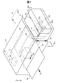
図1は、本発明の第1実施形態におけるタンクユニット20Aを備えるインクジェットプリンター10(以下、単に「プリンター10」と呼ぶ。)の構成を示す概略図である。図1には、プリンター10が通常の使用状態にあるときの重力方向を示す矢印Gが図示されている。本明細書において、「上」および「下」は、特に断らない限り、重力方向を基準とする上下方向を意味している。また、図1には、タンクユニット20Aが備えるインクタンク25Aを基準とする互いに直交する三方向を示す矢印X,Y,Zが図示されている。矢印X、Y,Zが示す方向については後述する。矢印G,X,Y,Zは、以下の説明において参照される各図においても、適宜、図示されている。
A. First embodiment:
FIG. 1 is a schematic diagram illustrating a configuration of an inkjet printer 10 (hereinafter simply referred to as “printer 10”) including a tank unit 20A according to the first embodiment of the present invention. FIG. 1 shows an arrow G indicating the direction of gravity when the printer 10 is in a normal use state. In the present specification, “upper” and “lower” mean the vertical direction based on the direction of gravity unless otherwise specified. FIG. 1 also shows arrows X, Y, and Z indicating three directions orthogonal to each other with reference to an ink tank 25A provided in the tank unit 20A. The directions indicated by the arrows X, Y, and Z will be described later. Arrows G, X, Y, and Z are also illustrated as appropriate in each drawing referred to in the following description.

プリンター10は、本発明における液体噴射システムの一実施形態であり、印刷媒体である印刷用紙PPに対してインク滴を吐出して、印刷用紙PPの印刷面に画像を形成する。プリンター10は、タンクユニット20Aと、印刷部30と、を備えている。タンクユニット20Aは、本発明におけるタンクユニットの一実施形態である。タンクユニット20Aは、複数のインクタンク25Aを備える。タンクユニット20Aは、印刷部30に対して水平方向に隣り合って連結された状態において、印刷部30に対して各インクタンク25Aが収容しているインクを供給可能である。タンクユニット20Aおよびインクタンク25Aの構成については後述する。   The printer 10 is an embodiment of the liquid ejecting system according to the present invention, and ejects ink droplets onto the printing paper PP, which is a printing medium, to form an image on the printing surface of the printing paper PP. The printer 10 includes a tank unit 20A and a printing unit 30. The tank unit 20A is an embodiment of the tank unit in the present invention. The tank unit 20A includes a plurality of ink tanks 25A. The tank unit 20 </ b> A can supply the ink stored in each ink tank 25 </ b> A to the printing unit 30 in a state where the tank unit 20 </ b> A is connected to the printing unit 30 in the horizontal direction. The configurations of the tank unit 20A and the ink tank 25A will be described later.

印刷部30は、液体噴射装置の下位概念に相当し、ケーシング部31と、印刷ヘッド部32と、印刷用紙PPの搬送機構33と、インク検出部34と、制御部35と、を備えている。ケーシング部31は、印刷部30の外装部であり、制御部35と、印刷ヘッド部32と、搬送機構33と、を内部に収容している。   The printing unit 30 corresponds to a subordinate concept of the liquid ejecting apparatus, and includes a casing unit 31, a print head unit 32, a printing paper PP transport mechanism 33, an ink detection unit 34, and a control unit 35. . The casing part 31 is an exterior part of the printing part 30, and accommodates the control part 35, the print head part 32, and the conveyance mechanism 33 inside.

印刷ヘッド部32は、印刷用紙PPの搬送路の上において、主走査方向SDに往復移動可能に設置されている。印刷ヘッド部32は、タンクユニット20Aから延出している複数のチューブ26を介してタンクユニット20Aの各インクタンク25Aに接続されており、制御部35の制御下において、各インクタンク25Aから供給されたインクを噴射可能である。印刷ヘッド部32は、本発明における液体噴射ヘッドの下位概念に相当する。搬送機構33は、搬送ローラーの回転駆動によって、印刷用紙PPを主走査方向SDに交差する搬送方向TDに搬送可能である。   The print head unit 32 is installed on the conveyance path of the printing paper PP so as to be reciprocally movable in the main scanning direction SD. The print head unit 32 is connected to each ink tank 25A of the tank unit 20A via a plurality of tubes 26 extending from the tank unit 20A, and is supplied from each ink tank 25A under the control of the control unit 35. Ink can be ejected. The print head unit 32 corresponds to a subordinate concept of the liquid jet head in the present invention. The transport mechanism 33 can transport the printing paper PP in the transport direction TD that intersects the main scanning direction SD by the rotational drive of the transport roller.

インク検出部34は、タンクユニット20Aから延出しているケーブル配線28を介して、タンクユニット20Aの各インクタンク25Aに電気的に接続される。インク検出部34は、各インクタンク25Aにおけるインクを検出するための電流を、ケーブル配線28を介して、各インクタンク25Aに周期的に印加し、その抵抗の変化を検出する。インク検出部34は、検出結果を制御部35に送信する。インク検出部34と各インクタンク25Aとの電気的な接続構成の詳細については後述する。   The ink detection unit 34 is electrically connected to each ink tank 25A of the tank unit 20A via a cable wiring 28 extending from the tank unit 20A. The ink detection unit 34 periodically applies a current for detecting ink in each ink tank 25 </ b> A to each ink tank 25 </ b> A via the cable wiring 28 to detect a change in resistance. The ink detection unit 34 transmits the detection result to the control unit 35. Details of the electrical connection configuration between the ink detector 34 and each ink tank 25A will be described later.

制御部35は、例えば、中央処理装置と主記憶装置とを備えるマイクロコンピューターによって構成される。制御部35は、中央処理装置が主記憶装置に種々のプログラムを読み込んで実行することによって、種々の機能を発揮する。本実施形態では、制御部35は、外部から入力された印刷データに基づいて、印刷部30を制御して印刷処理を実行する印刷処理部として機能する。印刷処理では、搬送機構33が印刷用紙PPを搬送し、印刷ヘッド部32が主走査方向SDに往復移動しつつインク滴を吐出することによって、印刷用紙PPの印刷面に印刷画像が形成される。   The control unit 35 is configured by a microcomputer including, for example, a central processing unit and a main storage device. The control unit 35 exhibits various functions when the central processing unit reads and executes various programs in the main storage device. In the present embodiment, the control unit 35 functions as a print processing unit that controls the printing unit 30 and executes a printing process based on print data input from the outside. In the printing process, the transport mechanism 33 transports the print paper PP, and the print head unit 32 ejects ink droplets while reciprocating in the main scanning direction SD, thereby forming a print image on the print surface of the print paper PP. .

また、制御部35は、インク検出部34によって検出された抵抗の変化に基づいて、各インクタンク25Aに所定の量以上のインクが収容されているか否かを検出するインク残量管理部としても機能する。制御部35は、インクタンク25Aにおいてインク残量が所定の量より少なくなったインク不足の状態を検出した場合には、例えば、ユーザーにインクの補充時期の到来を報知する報知処理などを実行する。また、制御部35は、印刷ヘッド部32によるインク滴の吐出が可能な残り回数の計測を開始し、当該残り回数が0になったときには、インクタンク25Aがインク切れの状態であるとして、印刷処理を中断する。   In addition, the control unit 35 may serve as an ink remaining amount management unit that detects whether each ink tank 25A contains a predetermined amount or more of ink based on a change in resistance detected by the ink detection unit 34. Function. When the controller 35 detects an ink shortage state in which the ink remaining amount is less than a predetermined amount in the ink tank 25A, for example, a notification process for notifying the user of the arrival of the ink replenishment time is performed. . In addition, the control unit 35 starts measuring the remaining number of times that the ink droplets can be ejected by the print head unit 32, and when the remaining number of times becomes 0, it is determined that the ink tank 25A is out of ink. Stop processing.

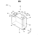
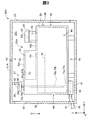
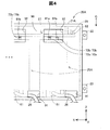
図1に加えて、図2〜図4を参照して、タンクユニット20Aおよびインクタンク25Aの構成を説明する。図2は、インクタンク25Aの外観構成を示す概略斜視図である。図3は、タンクユニット20Aの内部構成を示す概略断面図であり、装着されているインクタンク25Aを第6面部46(後述)に正対する方向に見たときの図である。図3では、インクタンク25Aの内部構造の一部が破線で模式的に図示されている。図4は、タンクユニット20Aの背面(後述)の一部を示す概略図である。   In addition to FIG. 1, the structure of the tank unit 20A and the ink tank 25A will be described with reference to FIGS. FIG. 2 is a schematic perspective view showing the external configuration of the ink tank 25A. FIG. 3 is a schematic cross-sectional view showing the internal configuration of the tank unit 20A, and is a view when the mounted ink tank 25A is viewed in a direction facing a sixth surface portion 46 (described later). In FIG. 3, a part of the internal structure of the ink tank 25A is schematically shown by a broken line. FIG. 4 is a schematic view showing a part of the back surface (described later) of the tank unit 20A.

タンクユニット20Aは、ケーシング部21Aと、複数のインクタンク25Aと、複数のチューブ26と、回路ユニット27と、ケーブル配線28と、を備える(図1)。ケーシング部21Aは、本発明における外装部の下位概念に相当する。本実施形態では、ケーシング部21Aは、樹脂製の略直方体形状の中空箱体として構成されている。ケーシング部21Aの内部空間21sには、複数のインクタンク25Aが、矢印Xによって示される幅方向(後述)に一列に配列された状態で固定されている。   The tank unit 20A includes a casing portion 21A, a plurality of ink tanks 25A, a plurality of tubes 26, a circuit unit 27, and a cable wiring 28 (FIG. 1). The casing portion 21A corresponds to a subordinate concept of the exterior portion in the present invention. In the present embodiment, the casing portion 21A is configured as a hollow box having a substantially rectangular parallelepiped shape made of resin. In the internal space 21s of the casing portion 21A, a plurality of ink tanks 25A are fixed in a state of being arranged in a line in the width direction (described later) indicated by an arrow X.

プリンター10の使用時には、タンクユニット20Aは、ケーシング部21Aに設けられている連結部22を介して、印刷部30のケーシング部31に、水平方向に隣り合う位置において連結される。本実施形態では、連結部22は、印刷部30のケーシング部31にネジ止めされるネジ止め部として構成されている。連結部22は、ネジ止め部として構成されていなくても良く、例えば、印刷部30のケーシング部31の壁部に係合する爪部によって構成されも良い。なお、本明細書において、「係合する」とは、対象物の移動方向が制限されるように所定の部位に係ることを意味する。   When the printer 10 is used, the tank unit 20A is connected to the casing unit 31 of the printing unit 30 at a position adjacent in the horizontal direction via the connection unit 22 provided in the casing unit 21A. In the present embodiment, the connecting portion 22 is configured as a screwing portion that is screwed to the casing portion 31 of the printing unit 30. The connecting portion 22 may not be configured as a screwing portion, and may be configured by a claw portion that engages with the wall portion of the casing portion 31 of the printing unit 30, for example. In the present specification, “engage” means that a predetermined part is involved so that the moving direction of the object is restricted.

ここで、使用状態にあるタンクユニット20に対して通常の操作(例えば、インクタンク25Aに対するインクの補充など)をおこなうときに、ユーザーの多くが正対することが想定される面側を「正面側」と呼び、その反対側を「背面側」と呼ぶ。例えば、ユーザーが通常の使用時にアクセスすることが想定されていないチューブ26やケーブル配線28が配設されている側が背面側であり、その反対側が正面側であると解釈することもできる。本実施形態のタンクユニット20Aにおいては、印刷部30に連結された状態のときに、印刷部30の方を向く側が背面側であり、印刷部30とは反対の方を向く側が正面側である。また、後述する基準姿勢において、後述の矢印Yの逆方向を向く側が背面側であり、矢印Yの方向を向く側が正面側である。また、正面に正対したときに右側に位置する側が右側面であり、左側に位置する面が左側面である。本実施形態では、タンクユニット20Aは、印刷部30に連結されている状態において、左側面が副走査方向TDを向き、右側面が副走査方向TDとは反対の方向を向く(図1)。   Here, when performing a normal operation (for example, replenishing ink to the ink tank 25A) with respect to the tank unit 20 in use, the surface side on which most of the users are supposed to face is referred to as “front side”. And the opposite side is called the “back side”. For example, the side on which the tube 26 and the cable wiring 28 that are not supposed to be accessed by the user during normal use is the back side, and the opposite side is the front side. In the tank unit 20A of the present embodiment, when connected to the printing unit 30, the side facing the printing unit 30 is the back side, and the side facing the opposite side of the printing unit 30 is the front side. . Further, in a reference posture described later, the side facing the reverse direction of the arrow Y described later is the back side, and the side facing the direction of the arrow Y is the front side. Further, the right side is the right side when facing the front, and the left side is the left side. In the present embodiment, in the state where the tank unit 20A is connected to the printing unit 30, the left side surface faces the sub scanning direction TD and the right side surface faces the direction opposite to the sub scanning direction TD (FIG. 1).

本実施形態では、ケーシング部21Aの正面側には、蓋部23が設けられている(図1,図3)。蓋部23は、ヒンジ機構24によってケーシング部21Aの本体に連結されており、矢印RDで示される方向に回動することによって開閉する。プリンター10のユーザーは、蓋部23を開くことによって、タンクユニット20A内に収容されている各インクタンク25Aにアクセスすることができる。なお、蓋部23は、回動によって開閉可能に構成されていなくても良く、例えば、着脱によって開閉可能に構成されていても良い。その他に、本実施形態では、ケーシング部21Aに、各インクタンク25Aに対する検査や試験を簡易化するための構成が設けられているが、その詳細については後述する。   In the present embodiment, a lid portion 23 is provided on the front side of the casing portion 21A (FIGS. 1 and 3). The lid portion 23 is connected to the main body of the casing portion 21A by a hinge mechanism 24, and opens and closes by rotating in the direction indicated by the arrow RD. The user of the printer 10 can access each ink tank 25A accommodated in the tank unit 20A by opening the lid portion 23. Note that the lid portion 23 does not have to be configured to be openable and closable by rotation, and may be configured to be openable and closable by attachment and detachment, for example. In addition, in the present embodiment, the casing portion 21A is provided with a configuration for simplifying the inspection and the test for each ink tank 25A. Details thereof will be described later.

複数のインクタンク25Aは、それぞれ異なる色のインクを収容している。インクタンク25Aは、本発明におけるタンクの下位概念に相当する。インクタンク25Aは、6つの面部41〜46を有する中空容器として構成されている(図2)。タンクユニット20Aでは、各インクタンク25Aは、ケーシング部21A内において、各面部41〜46が所定の方向を向く姿勢で固定される。インクタンク25Aの6つの面部41〜46について、印刷部30に連結されている状態のタンクユニット20A内でのインクタンク25Aの姿勢(図1)を基準として説明する。以下の説明では、この姿勢を「基準姿勢」とも呼ぶ。以下の説明におけるインクタンク25Aおよびタンクユニット20Aの方向に関する記載は、特に断らない限り、基準姿勢であるときの方向を意味している。他の実施形態においても同様である。   The plurality of ink tanks 25A contain different colors of ink. The ink tank 25A corresponds to a subordinate concept of the tank in the present invention. The ink tank 25A is configured as a hollow container having six surface portions 41 to 46 (FIG. 2). In the tank unit 20 </ b> A, each ink tank 25 </ b> A is fixed in a posture in which the surface portions 41 to 46 face a predetermined direction in the casing portion 21 </ b> A. The six surface portions 41 to 46 of the ink tank 25A will be described with reference to the posture of the ink tank 25A (FIG. 1) in the tank unit 20A connected to the printing unit 30. In the following description, this posture is also referred to as a “reference posture”. In the following description, the description relating to the directions of the ink tank 25A and the tank unit 20A means the direction in the reference posture unless otherwise specified. The same applies to other embodiments.

第1面部41は下方に向く底面部を構成し、第2面部42は上方を向く上面部を構成する(図2)。第3面部43は、第1面部41と第2面部42とに交差し、印刷部30とは反対側を向く面であり、ケーシング部21Aの蓋部23が開かれたときにユーザーの方に向く正面部を構成する。第4面部44は、第1面部41と第2面部42とに交差し、第3面部43とは反対の方向を向く面であり、印刷部30の方を向く背面部を構成する。第5面部45は、前記の4つの面部41〜44のそれぞれに交差し、第3面部43に正対したときに左側に位置する左側面部を構成する。第6面部46は、4つの面部41〜44のそれぞれに交差し、第3面部43に正対したときに、第3面部43とは反対側の右側に位置する右側面部を構成する。本実施形態では、第5面部45は、タンクユニット20Aの左側面側を向き、第6面部46がタンクユニット20Aの右側面側を向く。なお、本明細書において、2つの面部が「交差する」とは、2つの面部が相互に実際に交差する状態と、一方の面部の延長面が他方の面部に交差する状態と、2つの面部の延長面同士が交差する状態と、のいずれかの状態であることを意味する。   The first surface portion 41 constitutes a bottom surface portion facing downward, and the second surface portion 42 constitutes an upper surface portion facing upward (FIG. 2). The third surface portion 43 is a surface that intersects the first surface portion 41 and the second surface portion 42 and faces the side opposite to the printing portion 30, and is directed to the user when the lid portion 23 of the casing portion 21 </ b> A is opened. Configure the facing front. The fourth surface portion 44 intersects the first surface portion 41 and the second surface portion 42 and faces in the opposite direction to the third surface portion 43, and constitutes a back surface portion facing toward the printing unit 30. The fifth surface portion 45 intersects each of the four surface portions 41 to 44 and constitutes a left side surface portion located on the left side when facing the third surface portion 43. The sixth surface portion 46 intersects each of the four surface portions 41 to 44 and constitutes a right side surface portion located on the right side opposite to the third surface portion 43 when facing the third surface portion 43. In the present embodiment, the fifth surface portion 45 faces the left side surface side of the tank unit 20A, and the sixth surface portion 46 faces the right side surface side of the tank unit 20A. In this specification, two surface portions “intersect” means that two surface portions actually intersect each other, a state in which an extended surface of one surface portion intersects the other surface portion, and two surface portions. It means that it is in any of the state where the extended surfaces of the crossing.

続いて、インクタンク25Aを基準とする三方向を示す矢印X,Y,Zについて説明する。矢印Xは、インクタンク25Aの幅方向(左右方向)に平行な方向を示しており、第5面部45から第6面部46に向かう方向を示している。以下の説明において、「右」は矢印Xの方向側を意味し、「左」は矢印Xの逆方向側を意味している。本実施形態では、矢印Xの方向は、タンクユニット20Aにおける各インクタンク25Aの配列方向に平行である。矢印Yは、インクタンク25Aの奥行き方向(前後方向)に平行な方向を示しており、第4面部44から第3面部43に向かう方向を示している。以下の説明において、「前」は矢印Yの方向側を意味し、「後」は矢印Yの逆方向側を意味している。本実施形態では、矢印Yの方向は、タンクユニット20Aの背面から正面に向かう方向に一致する。矢印Zは、インクタンク25Aの高さ方向(上下方向)を示しており、第1面部41から第2面部42に向かう方向を示している。基準姿勢では、矢印Zは重力方向と反対の方向を向く。本実施形態では、インクタンク25Aの高さ方向は、タンクユニット20Aの高さ方向と一致する。   Subsequently, arrows X, Y, and Z indicating three directions with the ink tank 25A as a reference will be described. An arrow X indicates a direction parallel to the width direction (left-right direction) of the ink tank 25 </ b> A, and indicates a direction from the fifth surface portion 45 toward the sixth surface portion 46. In the following description, “right” means the direction side of the arrow X, and “left” means the reverse direction side of the arrow X. In the present embodiment, the direction of the arrow X is parallel to the arrangement direction of the ink tanks 25A in the tank unit 20A. An arrow Y indicates a direction parallel to the depth direction (front-rear direction) of the ink tank 25A, and indicates a direction from the fourth surface portion 44 toward the third surface portion 43. In the following description, “front” means the direction of the arrow Y, and “rear” means the direction opposite to the arrow Y. In the present embodiment, the direction of the arrow Y coincides with the direction from the back surface to the front surface of the tank unit 20A. An arrow Z indicates the height direction (vertical direction) of the ink tank 25 </ b> A, and indicates the direction from the first surface portion 41 toward the second surface portion 42. In the reference posture, the arrow Z points in the direction opposite to the direction of gravity. In the present embodiment, the height direction of the ink tank 25A coincides with the height direction of the tank unit 20A.

本実施形態のインクタンク25Aの第2面部42は、高さ位置が異なる第1上面部42aと第2上面部42bとを有している。第1上面部42aは、第2上面部42bよりも高い位置にある。また、第1上面部42aは、第4面部44側に位置しており、第2上面部42bは、第3面部43側に位置している。   The second surface portion 42 of the ink tank 25A of the present embodiment includes a first upper surface portion 42a and a second upper surface portion 42b that are different in height position. The 1st upper surface part 42a exists in a position higher than the 2nd upper surface part 42b. The first upper surface portion 42a is located on the fourth surface portion 44 side, and the second upper surface portion 42b is located on the third surface portion 43 side.

インクタンク25Aは、内部に、インク収容部50と、大気導入部51と、が形成されている(図3)。インク収容部50は、インクINを貯留可能な中空部位であり、本発明における液体収容部の下位概念に相当する。本実施形態では、インク収容部50は、第2上面部42bより下側の領域において、インクタンク25Aの幅方向および前後方向の全体にわたって形成されている。   The ink tank 25A has an ink storage portion 50 and an air introduction portion 51 formed therein (FIG. 3). The ink container 50 is a hollow part capable of storing the ink IN, and corresponds to a subordinate concept of the liquid container in the present invention. In the present embodiment, the ink containing portion 50 is formed over the entire width direction and the front-rear direction of the ink tank 25A in a region below the second upper surface portion 42b.

大気導入部51は、インクタンク25Aの外部からインク収容部50へと大気(空気)を導入する大気流路として機能する。大気導入部51は、第1上面部42aとインク収容部50との間に形成されている。大気導入部51は、大気室52と、大気取入口53と、大気導入口54と、を有する。大気室52は、外部から取り入れられた大気を収容可能な中空部位である。大気取入口53は、大気室52とインクタンク25Aとの外部とを連通する連通口である。大気導入口54は、大気室52とインク収容部50とを連通する連通口である。なお、大気室52は、大気導入口54を介してインク収容部50から溢れ出たインクINも貯留可能である。   The air introduction part 51 functions as an air flow path for introducing air (air) from the outside of the ink tank 25 </ b> A to the ink storage part 50. The air introduction part 51 is formed between the first upper surface part 42 a and the ink storage part 50. The air introduction unit 51 includes an air chamber 52, an air intake 53, and an air introduction port 54. The atmosphere chamber 52 is a hollow portion that can accommodate the atmosphere taken from the outside. The air intake 53 is a communication port that allows communication between the air chamber 52 and the outside of the ink tank 25A. The air introduction port 54 is a communication port that communicates the air chamber 52 and the ink storage unit 50. The atmosphere chamber 52 can also store ink IN that has overflowed from the ink storage section 50 via the atmosphere introduction port 54.

インクタンク25Aの第1面部41には、インク供給部61が形成されている(図2,図3)。インク供給部61は、インク収容部50のインクINを外部へと流出可能にする部位であり、インク収容部50の下端に連通する貫通孔62を有している。インク供給部61は、液体供給部の下位概念に相当する。本実施形態では、インク供給部61は、第4面部44側に位置し、インクINが矢印Yの逆方向に流出可能なように開口している。インク供給部61には可撓性を有する樹脂製のチューブ26が後方から気密に接続されている(図3)。各インクタンク25Aに収容されているインクINは、各インクタンク25Aに対して一本ずつ接続されているチューブ26を介して印刷部30の印刷ヘッド部32に供給される。なお、インク供給部61は、他の構成を有していても良く、例えば、矢印Zの方向に開口して、チューブ26が上方から装着される構成を有していても良い。   An ink supply unit 61 is formed on the first surface portion 41 of the ink tank 25A (FIGS. 2 and 3). The ink supply unit 61 is a part that allows the ink IN of the ink storage unit 50 to flow out to the outside, and has a through hole 62 that communicates with the lower end of the ink storage unit 50. The ink supply unit 61 corresponds to a subordinate concept of the liquid supply unit. In the present embodiment, the ink supply part 61 is located on the fourth surface part 44 side, and is open so that the ink IN can flow out in the direction opposite to the arrow Y. A flexible resin tube 26 is airtightly connected from the rear to the ink supply unit 61 (FIG. 3). The ink IN accommodated in each ink tank 25A is supplied to the print head unit 32 of the printing unit 30 via a tube 26 connected to each ink tank 25A one by one. The ink supply unit 61 may have other configurations, for example, may have a configuration that opens in the direction of the arrow Z and the tube 26 is mounted from above.

本実施形態では、タンクユニット20Aのケーシング部21Aにおける背面側の壁部90(以下、単に「背面壁部90」とも呼ぶ。)の下端に、各チューブ26をケーシング部21Aの外部に延出させるための複数の貫通孔91が設けられている(図4)。なお、貫通孔91は、背面壁部90の下端以外の領域に設けられていても良い。また、貫通孔91は背面壁部90に設けられていなくても良く、例えば、ケーシング部21Aの右側面側または左側面側の壁部に設けられていても良い。   In the present embodiment, each tube 26 is extended to the outside of the casing portion 21A at the lower end of the rear wall portion 90 (hereinafter also simply referred to as “rear wall portion 90”) in the casing portion 21A of the tank unit 20A. For this purpose, a plurality of through holes 91 are provided (FIG. 4). The through hole 91 may be provided in a region other than the lower end of the back wall portion 90. Moreover, the through-hole 91 may not be provided in the back wall part 90, for example, may be provided in the wall part by the side of the right side or the left side of the casing part 21A.

インクタンク25Aの第2上面部42bには、インク注入部63が設けられている(図2,図3)。インク注入部63は、インク収容部50にインクINを注入可能なように、外部からインク収容部50に連通する部位である。インク注入部63は、本発明における液体注入部の下位概念に相当する。本実施形態では、インク注入部63は、インク収容部50に連通する貫通孔64を有する円筒状の部位として構成されており、第2上面部42bから上方に向かって突出している。   An ink injection part 63 is provided on the second upper surface part 42b of the ink tank 25A (FIGS. 2 and 3). The ink injection unit 63 is a part that communicates with the ink storage unit 50 from the outside so that the ink IN can be injected into the ink storage unit 50. The ink injection part 63 corresponds to a subordinate concept of the liquid injection part in the present invention. In the present embodiment, the ink injection part 63 is configured as a cylindrical part having a through hole 64 communicating with the ink storage part 50, and protrudes upward from the second upper surface part 42b.

インク注入部63の上端部63tには、通常、貫通孔64を封止可能なキャップ部材65が気密に取り付けられている。キャップ部材65は、キャップ部材65は、例えば、ナイロンやポリプロピレンなどの合成樹脂によって作製される。ユーザーは、キャップ部材65をインク注入部63から取り外すことによって、インク収容部50にインクINを補充することができる。なお、本実施形態では、インク注入部63が第3面部43側に形成されているため、ユーザーはタンクユニット20Aの蓋部23を開けることによって、インク注入部63にアクセスすることができる(図1)。   Normally, a cap member 65 capable of sealing the through hole 64 is airtightly attached to the upper end portion 63t of the ink injection portion 63. The cap member 65 is made of a synthetic resin such as nylon or polypropylene, for example. The user can replenish the ink storage unit 50 with the ink IN by removing the cap member 65 from the ink injection unit 63. In this embodiment, since the ink injection portion 63 is formed on the third surface portion 43 side, the user can access the ink injection portion 63 by opening the lid portion 23 of the tank unit 20A (see FIG. 1).

本実施形態のインクタンク25Aでは、少なくとも第3面部43を構成する壁部の一部または全部が、インク収容部50におけるインクINの液面をユーザーが視認可能なように、透明または半透明に構成されている(図3)。これによって、ユーザーは、インクタンク25AにインクINを補充するときなどに、インクタンク25Aに収容されているインク量を視認することができる。   In the ink tank 25A of the present embodiment, at least a part or all of the wall portion constituting the third surface portion 43 is transparent or translucent so that the user can visually recognize the liquid level of the ink IN in the ink storage portion 50. It is configured (FIG. 3). Accordingly, the user can visually recognize the amount of ink stored in the ink tank 25A when the ink IN is refilled in the ink tank 25A.

第3面部43の壁面には、マーク部66が設けられている。マーク部66は、基準姿勢にあるインクタンク25Aに所定の基準量のインクINが収容されているときのインクINの液面の位置を示すように形成されている。インクタンク25Aでは、マーク部66の表示によって、インクタンク25Aに収容されるべきインクINの最大量(基準量)が規定されている。マーク部66は、例えば、第3面部43の壁面部における凸部または凹部として形成されていても良く、印刷やシールの貼付によって形成されていても良い。なお、第3面部43は全体が不透明に構成されていても良いし、マーク部66は省略されても良い。   A mark portion 66 is provided on the wall surface of the third surface portion 43. The mark portion 66 is formed to indicate the position of the liquid surface of the ink IN when a predetermined reference amount of ink IN is stored in the ink tank 25A in the reference posture. In the ink tank 25A, the maximum amount (reference amount) of the ink IN to be stored in the ink tank 25A is defined by the display of the mark portion 66. The mark part 66 may be formed as a convex part or a concave part in the wall surface part of the third surface part 43, for example, or may be formed by printing or sticking a seal. The entire third surface portion 43 may be configured to be opaque, or the mark portion 66 may be omitted.

本実施形態のインクタンク25Aでは、第4面部44側の第1上面部42aに、一対の電極ピン70a,70bが取り付けられている(図2,図3)。一対の電極ピン70a,70bは、本発明における電極部の下位概念に相当し、インク収容部50内に収容されているインクINの検出に用いられる。第1電極ピン70aおよび第2電極ピン70bは、例えば、金属ピンなど、棒状に延伸している導電性部材によって構成されている。各電極ピン70a,70bは、インクの付着によって表面に酸化被膜が生じてしまうことが抑制される部材によって構成されることが望ましい。各電極ピン70a,70bは、例えば、ステンレス鋼によって構成されても良い。   In the ink tank 25A of the present embodiment, a pair of electrode pins 70a and 70b are attached to the first upper surface portion 42a on the fourth surface portion 44 side (FIGS. 2 and 3). The pair of electrode pins 70a and 70b corresponds to a subordinate concept of the electrode portion in the present invention, and is used for detection of the ink IN stored in the ink storage portion 50. The 1st electrode pin 70a and the 2nd electrode pin 70b are comprised by the electroconductive member extended | stretched in rod shape, such as a metal pin, for example. Each of the electrode pins 70a and 70b is preferably composed of a member that suppresses the formation of an oxide film on the surface due to the adhesion of ink. Each electrode pin 70a, 70b may be comprised by stainless steel, for example.

各電極ピン70a,70bは、インク収容部50の底面に向かって延伸するように、第2上面部42bに設けられた貫通孔からインク収容部50内へと挿入されている。各電極ピン70a,70bの下端部である先端部71a,71bは、インク不足の状態のときのインク収容部50におけるインクINの液面の高さに位置している(図3)。各電極ピン70a,70bの上端部である後端部72a,72bは、外部から電気的に接続可能なように第2上面部42bから上方に突出している(図2,図3)。各電極ピン70a,70bの後端部72a,72bは、本発明における端子部の下位概念に相当する。   Each of the electrode pins 70 a and 70 b is inserted into the ink containing portion 50 from a through hole provided in the second upper surface portion 42 b so as to extend toward the bottom surface of the ink containing portion 50. The tip portions 71a and 71b, which are the lower ends of the electrode pins 70a and 70b, are positioned at the level of the liquid level of the ink IN in the ink containing portion 50 when the ink is insufficient (FIG. 3). The rear end portions 72a and 72b, which are the upper end portions of the electrode pins 70a and 70b, protrude upward from the second upper surface portion 42b so as to be electrically connectable from the outside (FIGS. 2 and 3). The rear ends 72a and 72b of the electrode pins 70a and 70b correspond to the subordinate concept of the terminal portion in the present invention.

本実施形態のタンクユニット20Aでは、各インクタンク25Aにおける各電極ピン70a,70bの後端部72a,72bには、共通の回路ユニット27が接続される(図1)。回路ユニット27は、基板部80と、ケーブル接続部82と、を有している(図3)。基板部80は、例えば、略長方形形状のプリント基板によって構成される。基板部80は、可撓性を有するフレキシブルプリント基板によって構成されても良い。基板部80は、各インクタンク25Aの上方において、矢印Xの方向を長辺に沿った方向として略水平に架設されている。   In the tank unit 20A of the present embodiment, a common circuit unit 27 is connected to the rear ends 72a and 72b of the electrode pins 70a and 70b in each ink tank 25A (FIG. 1). The circuit unit 27 has a substrate part 80 and a cable connection part 82 (FIG. 3). The board | substrate part 80 is comprised by the substantially rectangular shaped printed circuit board, for example. The board | substrate part 80 may be comprised by the flexible printed circuit board which has flexibility. The substrate 80 is installed substantially horizontally above each ink tank 25A with the direction of the arrow X as the direction along the long side.

基板部80の下側の面には、各インクタンク25Aの一対の電極ピン70a,70bに対応して設けられた複数組の一対の基板端子81a,81bが矢印Xの方向に配列されている(図4)。第1基板端子81aは、第1電極ピン70aの後端部72aに電気的に接触する。第2基板端子81bは、第2電極ピン70bの後端部72bに電気的に接触する。   On the lower surface of the substrate portion 80, a plurality of pairs of substrate terminals 81a, 81b provided corresponding to the pair of electrode pins 70a, 70b of each ink tank 25A are arranged in the direction of arrow X. (FIG. 4). The first substrate terminal 81a is in electrical contact with the rear end portion 72a of the first electrode pin 70a. The second substrate terminal 81b is in electrical contact with the rear end portion 72b of the second electrode pin 70b.

ケーブル接続部82は、基板部80の端部に固定されている(図1)。ケーブル接続部82には、基板部80に形成されている配線パターン(図示は省略)を介して、各基板端子81a,81bに対する導電経路が集約されている。ケーブル接続部82は、タンクユニット20Aのケーブル配線28と接続されている。ケーブル配線28は、ケーシング部21Aの壁部に設けられている貫通孔(図示は省略)を介して、ケーシング部21Aから延出し、印刷部30のインク検出部34に接続されている。これによって、各インクタンク25Aは、印刷部30のインク検出部34に電気的に接続される。   The cable connecting portion 82 is fixed to the end portion of the substrate portion 80 (FIG. 1). In the cable connection portion 82, conductive paths for the respective substrate terminals 81 a and 81 b are collected through a wiring pattern (not shown) formed in the substrate portion 80. The cable connecting portion 82 is connected to the cable wiring 28 of the tank unit 20A. The cable wiring 28 extends from the casing part 21 </ b> A through a through hole (not shown) provided in the wall part of the casing part 21 </ b> A and is connected to the ink detection part 34 of the printing part 30. Accordingly, each ink tank 25A is electrically connected to the ink detection unit 34 of the printing unit 30.

インク検出部34は、印刷処理の実行中や印刷処理の休止中に、第1電極ピン70aに対して、周期的に電流を印加し、第1電極ピン70aと第2電極ピン70bとの間の抵抗を検出する。インク収容部50内のインクINが消費され、その液面が各電極ピン70a,70bの先端部71a,71bより低い位置まで低下し、インクINと各電極ピン70a,70bとの間の電気的導通が遮断されると、電極ピン70a,70b同士の間の抵抗が増大する。制御部35は、インク検出部34によって検出される抵抗が所定の閾値以上に増大したときに、インク不足の状態を検出する。なお、制御部35は、各電極ピン70a,70bにおけるインクINとの接触面積の変化に応じた抵抗の変化を、インク収容部50におけるインク量の変化として検出しても良い。   The ink detection unit 34 periodically applies a current to the first electrode pin 70a during the execution of the printing process or during the pause of the printing process, and between the first electrode pin 70a and the second electrode pin 70b. Detect the resistance. The ink IN in the ink containing portion 50 is consumed, and the liquid level is lowered to a position lower than the tip portions 71a and 71b of the electrode pins 70a and 70b, and the electrical connection between the ink IN and the electrode pins 70a and 70b. When conduction is interrupted, the resistance between the electrode pins 70a and 70b increases. The control unit 35 detects an ink shortage state when the resistance detected by the ink detection unit 34 increases to a predetermined threshold value or more. The control unit 35 may detect a change in resistance according to a change in the contact area between the electrode pins 70 a and 70 b and the ink IN as a change in the ink amount in the ink containing unit 50.

本実施形態のタンクユニット20Aでは、インク注入部63が第3面部43側に位置し、各電極ピン70a,70bの後端部72a,72bは第4面部44側に位置している。このように両者が前後方向において離間して形成されているため、インク注入部63を介してインクINが補充されるときに、インク滴が各電極ピン70a,70bの後端部72a,72bに飛散して付着してしまうことが抑制される。また、本実施形態のタンクユニット20Aでは、各電極ピン70a,70bの後端部72a,72bは、インク注入部63の上端部63tよりも高い位置に位置している。従って、インク注入部63からのインク滴が各電極ピン70a,70bの後端部72a,72bに到達することがさらに抑制されている。   In the tank unit 20A of the present embodiment, the ink injection portion 63 is located on the third surface portion 43 side, and the rear end portions 72a and 72b of the electrode pins 70a and 70b are located on the fourth surface portion 44 side. Thus, since both are formed apart in the front-rear direction, when the ink IN is replenished via the ink injection portion 63, ink droplets are applied to the rear end portions 72a, 72b of the electrode pins 70a, 70b. Scattering and adhesion are suppressed. In the tank unit 20 </ b> A of the present embodiment, the rear end portions 72 a and 72 b of the electrode pins 70 a and 70 b are positioned higher than the upper end portion 63 t of the ink injection portion 63. Therefore, ink droplets from the ink injection part 63 are further suppressed from reaching the rear end parts 72a and 72b of the electrode pins 70a and 70b.

ここで、本実施形態のタンクユニット20Aでは、ケーシング部21Aの背面壁部90に、略四角形状の開口形状を有している複数の貫通窓92が設けられている(図4)。複数の貫通窓92は、各インクタンク25Aに対応して一つずつ設けられている。貫通窓92は、各インクタンク25Aにおける電極ピン70a,70aの後端部72a,72bを、ケーシング部21Aの外部に露出させることができるように設けられている。本明細書において、「外部に露出させる」とは、対象物を外部から直接的に視認でき、かつ、外部から、直接的、または、間接的に接触できる状態にすることを意味する。また、「外部に露出させることができるように設けられている」構成には、対象物が常に外部に露出する状態にされている構成のみならず、対象物が一時的に露出しない状態にされている構成も含まれる。つまり、例えば、後述する第6実施形態において示されているように、貫通窓92が封止部材などによって一時的に封止された状態にされている構成も含まれる。   Here, in the tank unit 20A of the present embodiment, a plurality of through windows 92 having a substantially square opening shape are provided on the back wall portion 90 of the casing portion 21A (FIG. 4). A plurality of through windows 92 are provided for each ink tank 25A. The through window 92 is provided so that the rear end portions 72a and 72b of the electrode pins 70a and 70a in each ink tank 25A can be exposed to the outside of the casing portion 21A. In the present specification, “exposing to the outside” means that an object can be directly visually recognized from the outside and can be directly or indirectly contacted from the outside. In addition, the configuration “provided to be exposed to the outside” includes not only a configuration in which the object is always exposed to the outside, but also a state in which the object is not temporarily exposed. Also included is the configuration. That is, for example, as shown in a sixth embodiment described later, a configuration in which the through window 92 is temporarily sealed by a sealing member or the like is also included.

本実施形態では、複数の貫通窓92は、その開口方向に見たときに、各インクタンク25Aにおける電極ピン70a,70aの後端部72a,72bが貫通窓92内に位置するように設けられている。本実施形態では、貫通窓92の開口方向は、背面壁部90およびインクタンク25Aの第4面部44に正対する方向であり、矢印Yに平行な方向である。本実施形態では、複数の貫通窓92によってケーシング部21Aに形成されている開口が、本発明における開口の下位概念に相当する。なお、貫通窓92の開口形状は、略四角形状を有していなくても良く、例えば、円形形状など、種々の形状を有していても良い。   In the present embodiment, the plurality of through windows 92 are provided so that the rear end portions 72a and 72b of the electrode pins 70a and 70a in each ink tank 25A are positioned in the through windows 92 when viewed in the opening direction. ing. In the present embodiment, the opening direction of the through window 92 is a direction facing the back wall 90 and the fourth surface 44 of the ink tank 25 </ b> A, and is parallel to the arrow Y. In the present embodiment, the opening formed in the casing portion 21A by the plurality of through windows 92 corresponds to a subordinate concept of the opening in the present invention. In addition, the opening shape of the through window 92 may not have a substantially rectangular shape, and may have various shapes such as a circular shape.

本実施形態のタンクユニット20Aによれば、貫通窓92を介して、各インクタンク25Aの各電極ピン70a,70aに対する電気的導通性の検査を、タンクユニット20Aにおいて回路ユニット27が接続された状態のままで、簡易におこなうができる。各電極ピン70a,70aに対する電気的導通性の検査の方法については後述する。また、本実施形態のタンクユニット20Aによれば、貫通窓92を介して、電極ピン70a,70aの後端部72a,72bと、基板部80の各基板端子81a,81bとの接続状態を視認することができる。   According to the tank unit 20A of the present embodiment, the electrical continuity test for each electrode pin 70a, 70a of each ink tank 25A is performed via the through window 92 in a state where the circuit unit 27 is connected in the tank unit 20A. You can do it easily. A method of inspecting electrical continuity with respect to each electrode pin 70a, 70a will be described later. Further, according to the tank unit 20A of the present embodiment, the connection state between the rear end portions 72a and 72b of the electrode pins 70a and 70a and the substrate terminals 81a and 81b of the substrate portion 80 is visually confirmed through the through window 92. can do.

その他に、本実施形態のタンクユニット20Aでは、プリンター10が通常の使用状態にあるときには、タンクユニット20Aの背面壁部90は印刷部30のケーシング部31の壁面に正対し、貫通窓92が閉塞された状態となる(図1)。そのため、貫通窓92を介して、各インクタンク25Aと回路ユニット27との接続部位に埃やインクのミストなどの異物が侵入してしまうことが抑制される。また、ユーザーが誤って、各インクタンク25Aと回路ユニット27との接続部位に触れてしまうことが抑制される。   In addition, in the tank unit 20A of the present embodiment, when the printer 10 is in a normal use state, the back wall portion 90 of the tank unit 20A faces the wall surface of the casing portion 31 of the printing unit 30, and the through window 92 is closed. (FIG. 1). Therefore, foreign matter such as dust and ink mist is prevented from entering the connecting portion between each ink tank 25 </ b> A and the circuit unit 27 through the through window 92. Further, it is possible to prevent the user from touching the connection portion between each ink tank 25A and the circuit unit 27 by mistake.

図5,図6を参照して、各インクタンク25Aの各電極ピン70a,70aに対する電気的導通性の検査の方法の一例を説明する。図5は、当該検査に用いられる検査装置200の構成を示す概略図である。図5には、タンクユニット20Aにおける貫通窓92近傍の部位も図示されている。図6は、検査装置200によって検査しているときの状態を示す模式図である。図6には、矢印Xの方向に見たときの回路ユニット27とインクタンク25Aの接続部位が図示されている。   With reference to FIGS. 5 and 6, an example of a method for inspecting electrical continuity with respect to the electrode pins 70a and 70a of each ink tank 25A will be described. FIG. 5 is a schematic diagram showing a configuration of an inspection apparatus 200 used for the inspection. FIG. 5 also shows a portion near the through window 92 in the tank unit 20A. FIG. 6 is a schematic diagram showing a state when the inspection apparatus 200 is inspecting. FIG. 6 shows a connection portion between the circuit unit 27 and the ink tank 25A when viewed in the direction of the arrow X.

検査装置200は、コネクター部210と、本体部220と、を備える(図5)。コネクター部210は、検査対象であるインクタンク25Aの一対の電極ピン70a,70bの後端部72a,72bの側面に電気的に接続される部位である。コネクター部210は、貫通窓92を介してタンクユニット20A内に挿入可能なサイズを有している。   The inspection device 200 includes a connector part 210 and a main body part 220 (FIG. 5). The connector portion 210 is a portion that is electrically connected to the side surfaces of the rear end portions 72a and 72b of the pair of electrode pins 70a and 70b of the ink tank 25A to be inspected. The connector part 210 has a size that can be inserted into the tank unit 20 </ b> A via the through window 92.

コネクター部210は、一対のピン端子211,212を備えている。各ピン端子211,212は導電性を有する金属ピンによって構成されている。各ピン端子211,212は、コネクター部210の先端において平行に突出するように配列されている。各ピン端子211,212の長さは互いにほぼ同じであり、各ピン端子211,212の間の距離は、一対の電極ピン70a,70bの間の距離とほぼ同じである。   The connector unit 210 includes a pair of pin terminals 211 and 212. Each of the pin terminals 211 and 212 is composed of a conductive metal pin. The pin terminals 211 and 212 are arranged so as to protrude in parallel at the tip of the connector part 210. The lengths of the pin terminals 211 and 212 are substantially the same, and the distance between the pin terminals 211 and 212 is substantially the same as the distance between the pair of electrode pins 70a and 70b.

各ピン端子211,212は、コネクター部210が貫通窓92を介してタンクユニット20A内に水平に挿入されたときに、それの先端部211s,212sが各電極ピン70a,70bの後端部72a,72bの側面に接触可能である(図6)。第1ピン端子211の先端部211sが、第1電極ピン70aの後端部72aに接触し、第2ピン端子212の先端部212sが、第2電極ピン70bの後端部72bに接触する。   When the connector part 210 is horizontally inserted into the tank unit 20A via the through window 92, each pin terminal 211, 212 has its tip part 211s, 212s as the rear end part 72a of each electrode pin 70a, 70b. , 72b can be contacted (FIG. 6). The front end portion 211s of the first pin terminal 211 is in contact with the rear end portion 72a of the first electrode pin 70a, and the front end portion 212s of the second pin terminal 212 is in contact with the rear end portion 72b of the second electrode pin 70b.

検査装置200の本体部220は、導電線201と、電流印加部221と、電流計測部222と、制御部223と、報知部224と、を備えている(図5)。電流印加部221は、導電線201を介して、コネクター部210のピン端子211,212に電気的に接続されている。電流印加部221は、電源部(図示は省略)を有しており、導電線201を介して、ピン端子211,212に所定の電流を印加可能である。電流計測部222は、電流印加部221によって印加される電流を計測可能なように、導電線201に接続されている。   The main body 220 of the inspection apparatus 200 includes a conductive wire 201, a current application unit 221, a current measurement unit 222, a control unit 223, and a notification unit 224 (FIG. 5). The current application unit 221 is electrically connected to the pin terminals 211 and 212 of the connector unit 210 via the conductive wire 201. The current application unit 221 includes a power supply unit (not shown), and can apply a predetermined current to the pin terminals 211 and 212 via the conductive wire 201. The current measuring unit 222 is connected to the conductive wire 201 so that the current applied by the current applying unit 221 can be measured.

制御部223は、中央処理装置と主記憶装置とを備えるマイクロコンピューターによって構成される。制御部223は、ユーザーによるスイッチ(図示は省略)操作に応じて、電流印加部221によるピン端子211,212に対する電流の印加を制御する。制御部223は、電流計測部222から計測結果を表す信号を受信し、報知部224に計測結果を出力する。報知部224は、例えば、液晶ディスプレイなどの表示部によって構成され、制御部223から受信した計測結果をユーザーに報知する。   The control unit 223 is configured by a microcomputer including a central processing unit and a main storage device. The control unit 223 controls current application to the pin terminals 211 and 212 by the current application unit 221 in accordance with a switch (not shown) operation by the user. The control unit 223 receives a signal representing the measurement result from the current measurement unit 222 and outputs the measurement result to the notification unit 224. For example, the notification unit 224 includes a display unit such as a liquid crystal display, and notifies the user of the measurement result received from the control unit 223.

検査の際には、まず、タンクユニット20Aが、印刷部30のケーシング部31から取り外される。このとき、各インクタンク25Aにはインクが収容された状態である。また、ケーブル配線28は、回路ユニット27のケーブル接続部82から外されることが望ましい。次に、検査装置200のコネクター部210が、タンクユニット20Aの背面壁部90における貫通窓92から、ケーシング部21A内に挿入される。そして、コネクター部210のピン端子211,212が、インクタンク25Aにおける各電極ピン70a,70bの後端部72a,72bに接続される。   In the inspection, first, the tank unit 20 </ b> A is removed from the casing portion 31 of the printing unit 30. At this time, the ink is stored in each ink tank 25A. The cable wiring 28 is preferably disconnected from the cable connection portion 82 of the circuit unit 27. Next, the connector part 210 of the inspection apparatus 200 is inserted into the casing part 21A from the through window 92 in the back wall part 90 of the tank unit 20A. The pin terminals 211 and 212 of the connector part 210 are connected to the rear end parts 72a and 72b of the electrode pins 70a and 70b in the ink tank 25A.

この状態において、ユーザーによるスイッチ操作がおこなわれると、制御部223は、電流印加部221によって、ピン端子211,212に対して電流を印加する。制御部223は、電流計測部222による計測結果を、報知部224を介してユーザーに対して報知する。制御部223は、電流計測部222によって、所定の範囲外の異常な電流値が検出された場合や、電流の非導通状態などが検出された場合には、報知部224を介してユーザーにその旨を報知する。このように、検査装置200を用いることによって、インクタンク25Aの電極ピン70a,70bに対する電気的導通性の検査をより簡易におこなうことができる。   In this state, when a switch operation is performed by the user, the control unit 223 applies a current to the pin terminals 211 and 212 by the current application unit 221. The control unit 223 notifies the user of the measurement result obtained by the current measurement unit 222 via the notification unit 224. When the current measurement unit 222 detects an abnormal current value outside a predetermined range or when a current non-conduction state is detected, the control unit 223 notifies the user via the notification unit 224. Inform the effect. As described above, by using the inspection device 200, it is possible to more easily inspect the electrical continuity with respect to the electrode pins 70a and 70b of the ink tank 25A.

以上のように、本実施形態のプリンター10およびタンクユニット20Aによれば、各インクタンク25Aに対する電気的導通性の検査を、タンクユニット20Aに装着された状態のままで、簡易に実行することができる。その他に、上記実施形態中において説明した種々の作用効果を奏することができる。   As described above, according to the printer 10 and the tank unit 20A of the present embodiment, the electrical continuity test for each ink tank 25A can be easily performed while being attached to the tank unit 20A. it can. In addition, various functions and effects described in the above embodiment can be achieved.

B.第2実施形態:
図7は、本発明の第2実施形態におけるタンクユニット20Bの構成を示す概略図である。図7には、タンクユニット20Bの背面の一部が、図4と同様に図示されている。第2実施形態のタンクユニット20Bは、以下に説明する点以外は、第1実施形態で説明したタンクユニット20Aとほぼ同じ構成を有している。第2実施形態のプリンターの構成は、タンクユニット20Aの構成が異なっている点以外は、第1実施形態のプリンター10(図1)とほぼ同じである。以下の説明および参照図では、第1実施形態で説明したのと同じ、または、対応する各構成部に対して、第1実施形態で用いたのと同じ符号が用いられている。
B. Second embodiment:
FIG. 7 is a schematic diagram showing the configuration of the tank unit 20B in the second embodiment of the present invention. 7 shows a part of the back surface of the tank unit 20B in the same manner as in FIG. The tank unit 20B of the second embodiment has substantially the same configuration as the tank unit 20A described in the first embodiment, except for the points described below. The configuration of the printer of the second embodiment is substantially the same as that of the printer 10 (FIG. 1) of the first embodiment except that the configuration of the tank unit 20A is different. In the following description and reference drawings, the same reference numerals as those used in the first embodiment are used for the same or corresponding components described in the first embodiment.

タンクユニット20Bでは、ケーシング部21Bに、背面壁部90が設けられておらず、ケーシング部21Bの背面側全体が開口することによって背面開口93が形成されている。タンクユニット20Bでは、印刷部30との連結状態が解除されたときに、各インクタンク25Aの第4面部44側の全体が、背面開口93を介して外部に露出する。第2実施形態では、背面開口93が本発明における開口の下位概念に相当する。   In the tank unit 20B, the back wall 90 is not provided in the casing part 21B, and a back opening 93 is formed by opening the entire back side of the casing part 21B. In the tank unit 20 </ b> B, when the connection state with the printing unit 30 is released, the entire side of the fourth surface 44 of each ink tank 25 </ b> A is exposed to the outside through the back surface opening 93. In the second embodiment, the rear opening 93 corresponds to a subordinate concept of the opening in the present invention.

第2実施形態のタンクユニット20Bによれば、背面開口93を介して、各インクタンク25Aの一対の電極ピン70a,70bに対する電気的導通性の検査を簡易におこなうことができる。この検査には、第1実施形態で説明した検査装置200を用いることができる。また、第2実施形態のタンクユニット20Bであれば、背面開口93の開口面積が第1実施形態の貫通窓92の開口面積よりも大きいため、ケーシング部21Bの外部からの各電極ピン70a,70bの後端部72a,72bに対するアクセス性が高められている。その他に、第2実施形態のタンクユニット20Bおよびそれを備えるプリンターによれば、第1実施形態で説明したのと同様な種々の作用効果を奏することができる。   According to the tank unit 20B of the second embodiment, the electrical continuity test for the pair of electrode pins 70a and 70b of each ink tank 25A can be easily performed via the back surface opening 93. The inspection apparatus 200 described in the first embodiment can be used for this inspection. In the tank unit 20B of the second embodiment, since the opening area of the back opening 93 is larger than the opening area of the through window 92 of the first embodiment, the electrode pins 70a and 70b from the outside of the casing portion 21B. The accessibility to the rear end portions 72a and 72b is improved. In addition, according to the tank unit 20B of the second embodiment and the printer including the same, various functions and effects similar to those described in the first embodiment can be achieved.

C.第3実施形態:
図8,図9を参照して、第3実施形態におけるタンクユニット20Cの構成を説明する。図8は、第3実施形態のタンクユニット20Cが備えるインクタンク25Cの構成を示す概略斜視図である。図9は、第3実施形態のタンクユニット20Cの背面の一部を示す概略図である。第3実施形態におけるタンクユニット20Cの構成は、装着されるインクタンク25Cの構成が異なる点と、貫通窓92の形成位置が異なる点以外は、第1実施形態のタンクユニット20Aとほぼ同じである。第3実施形態のプリンターの構成は、タンクユニット20Cを備えている点以外は、第1実施形態のプリンター10(図1)とほぼ同じである。以下の説明および参照図では、第1実施形態で説明したのと同じ、または、対応する各構成部に対して、第1実施形態で用いたのと同じ符号が用いられている。
C. Third embodiment:
The configuration of the tank unit 20C in the third embodiment will be described with reference to FIGS. FIG. 8 is a schematic perspective view showing the configuration of an ink tank 25C provided in the tank unit 20C of the third embodiment. FIG. 9 is a schematic view showing a part of the back surface of the tank unit 20C of the third embodiment. The configuration of the tank unit 20C in the third embodiment is substantially the same as the tank unit 20A in the first embodiment, except that the configuration of the ink tank 25C to be mounted is different and the formation position of the through window 92 is different. . The configuration of the printer of the third embodiment is substantially the same as that of the printer 10 (FIG. 1) of the first embodiment except that a tank unit 20C is provided. In the following description and reference drawings, the same reference numerals as those used in the first embodiment are used for the same or corresponding components described in the first embodiment.

第3実施形態のインクタンク25Cの構成は、一対の電極部75a,75bが設けられている点以外は、第1実施形態のインクタンク25Aとほぼ同じである。第1電極部75aは、第1電極パッド部76aと、第1導電部77aと、を有する。第2電極部75bは、第2電極パッド部76bと、第2導電部77bと、を有する。   The configuration of the ink tank 25C of the third embodiment is substantially the same as the ink tank 25A of the first embodiment except that a pair of electrode portions 75a and 75b are provided. The first electrode portion 75a includes a first electrode pad portion 76a and a first conductive portion 77a. The second electrode portion 75b includes a second electrode pad portion 76b and a second conductive portion 77b.

第1電極パッド部76aおよび第2電極パッド部76bは、それぞれほぼ同じサイズの略円盤形状を有しており、第4面部44上のほぼ同じ高さ位置において、矢印Xの方向に配列されている。インクタンク25Cを矢印Yの方向に見たときに、第1電極パッド部76aは第1電極ピン70aと重なる位置に形成されており、第2電極パッド部76bは第2電極ピン70bと重なる位置に形成されている。   The first electrode pad portion 76a and the second electrode pad portion 76b have substantially the same disk shape and are arranged in the direction of the arrow X at substantially the same height position on the fourth surface portion 44. Yes. When the ink tank 25C is viewed in the direction of the arrow Y, the first electrode pad portion 76a is formed at a position overlapping the first electrode pin 70a, and the second electrode pad portion 76b is positioned overlapping the second electrode pin 70b. Is formed.

第1導電部77aは、第1電極パッド部76aと第1電極ピン70aの後端部72aとの間に延在して、両者を電気的に接続する。同様に、第2導電部77bは、第2電極パッド部76bと第2電極ピン70bの後端部72bとの間に延在して、両者を電気的に接続する。一対の電極部75a,75bは、例えば、導電ペーストのスクリーン印刷などによって形成されても良いし、金属板などの導電性板状部材によって形成されても良い。   The first conductive portion 77a extends between the first electrode pad portion 76a and the rear end portion 72a of the first electrode pin 70a, and electrically connects both. Similarly, the second conductive portion 77b extends between the second electrode pad portion 76b and the rear end portion 72b of the second electrode pin 70b, and electrically connects the two. The pair of electrode portions 75a and 75b may be formed by, for example, screen printing of a conductive paste, or may be formed by a conductive plate member such as a metal plate.

第3実施形態のタンクユニット20Cでは、背面壁部90の貫通窓92を、その開口方向である矢印Yの方向に見たときに、第4面部44上の電極パッド部76a,76bが、貫通窓92内に位置する。タンクユニット20Cでは、貫通窓92から各電極ピン70a,70bの後端部72a,72bが露出しておらず、電極パッド部76a,76bが露出している。なお、電極パッド部76a,76bは、電極ピン70a,70bの後端部72a,72bと電気的に導通しているため、外部との電気的接続を可能にするインクタンク25Cの端子部の一部であると解釈することができる。   In the tank unit 20C of the third embodiment, when the through window 92 of the back wall 90 is viewed in the direction of the arrow Y that is the opening direction, the electrode pad portions 76a and 76b on the fourth surface 44 are penetrated. Located in window 92. In the tank unit 20C, the rear end portions 72a and 72b of the electrode pins 70a and 70b are not exposed from the through window 92, and the electrode pad portions 76a and 76b are exposed. The electrode pad portions 76a and 76b are electrically connected to the rear end portions 72a and 72b of the electrode pins 70a and 70b. Therefore, the electrode pad portions 76a and 76b are one of the terminal portions of the ink tank 25C that enables electrical connection to the outside. It can be interpreted as a part.

第3実施形態のタンクユニット20Cによれば、貫通窓92から露出している電極パッド部76a,76bを介して、各インクタンク25Cにおける電極ピン70a,70bの電気的導通性の検査をおこなうことができる。この検査には、第1実施形態で説明したのと同様な検査装置200を用いることもできる。また、第3実施形態のタンクユニット20Cであれば、回路ユニット27と電極ピン70a,70bとの接続部位自体は貫通窓92から露出しないため、当該接続部位の保護性が高められている。その他に、第3実施形態のタンクユニット20Cおよびそれを備えるプリンターであれば、第1実施形態で説明したのと同様な種々の作用効果を奏することができる。   According to the tank unit 20C of the third embodiment, the electrical continuity of the electrode pins 70a and 70b in each ink tank 25C is tested through the electrode pad portions 76a and 76b exposed from the through window 92. Can do. For this inspection, the same inspection apparatus 200 as described in the first embodiment can be used. Further, in the tank unit 20C of the third embodiment, since the connection part itself between the circuit unit 27 and the electrode pins 70a and 70b is not exposed from the through window 92, the protection of the connection part is enhanced. In addition, the tank unit 20 </ b> C of the third embodiment and a printer including the tank unit 20 </ b> C can exhibit various functions and effects similar to those described in the first embodiment.

D.第4実施形態:
図10〜図12を参照して、第4実施形態におけるタンクユニット20Dおよびインクタンク25Dの構成を説明する。図10は、第4実施形態のインクタンク25Dの外観構成を示す概略斜視図である。図11は、第4実施形態のタンクユニット20Dの内部構成を示す概略断面図であり、装着されているインクタンク25Dを第6面部46に正対する方向に見たときの図である。図11では、インクタンク25Dの内部構造の一部が破線で模式的に図示されている。図12は、第4実施形態のタンクユニット20Dの背面の一部を示す概略図である。第4実施形態におけるタンクユニット20Dの構成は、インクタンク25Dの構成が異なっている点以外は、第1実施形態のタンクユニット20Aとほぼ同じである。第4実施形態のプリンターの構成は、タンクユニット20Dを備えている点以外は、第1実施形態のプリンター10(図1)とほぼ同じである。以下の説明および参照図では、第1実施形態で説明したのと同じ、または、対応する各構成部に対して、第1実施形態で用いたのと同じ符号が用いられている。
D. Fourth embodiment:
The configuration of the tank unit 20D and the ink tank 25D in the fourth embodiment will be described with reference to FIGS. FIG. 10 is a schematic perspective view showing the external configuration of the ink tank 25D of the fourth embodiment. FIG. 11 is a schematic cross-sectional view showing the internal configuration of the tank unit 20D of the fourth embodiment, and is a view when the attached ink tank 25D is viewed in the direction facing the sixth surface portion 46. FIG. In FIG. 11, a part of the internal structure of the ink tank 25D is schematically illustrated by a broken line. FIG. 12 is a schematic view showing a part of the back surface of the tank unit 20D of the fourth embodiment. The configuration of the tank unit 20D in the fourth embodiment is substantially the same as the tank unit 20A of the first embodiment except that the configuration of the ink tank 25D is different. The configuration of the printer of the fourth embodiment is substantially the same as that of the printer 10 (FIG. 1) of the first embodiment, except that the tank unit 20D is provided. In the following description and reference drawings, the same reference numerals as those used in the first embodiment are used for the same or corresponding components described in the first embodiment.

第4実施形態のタンクユニット20Dが備えるインクタンク25Dの構成は、以下に説明する点以外は、第1実施形態のインクタンク25Aとほぼ同じである。インクタンク25Dの第2面部42には、第4面部44側の端の領域に、第2上面部42bとほぼ同じ高さ位置にある第3上面部42cが設けられている(図10,図11)。第1上面部42aは、第3面部43側の第2上面部42bと、第4面部44側の第3上面部42cと、によって前後方向に挟まれている。第3上面部42cと第1上面部42aとの間には、矢印Yの逆方向に向く面である段差面42dが形成されている。   The configuration of the ink tank 25D provided in the tank unit 20D of the fourth embodiment is substantially the same as the ink tank 25A of the first embodiment except for the points described below. The second surface portion 42 of the ink tank 25D is provided with a third upper surface portion 42c that is at the same height as the second upper surface portion 42b in the end region on the fourth surface portion 44 side (FIGS. 10 and 10). 11). The first upper surface portion 42a is sandwiched between the second upper surface portion 42b on the third surface portion 43 side and the third upper surface portion 42c on the fourth surface portion 44 side in the front-rear direction. Between the third upper surface portion 42c and the first upper surface portion 42a, a step surface 42d that is a surface facing in the reverse direction of the arrow Y is formed.

インクタンク25Dでは、インク収容部50は、第2上面部42bおよび第3上面部42cより下方の領域に形成されている(図11)。また、大気導入部51は、第1上面部42aの下方であって、インク収容部50の上方の位置に形成されており、段差面42dに対して矢印Yの方向に隣り合う位置に形成されている。   In the ink tank 25D, the ink storage portion 50 is formed in a region below the second upper surface portion 42b and the third upper surface portion 42c (FIG. 11). The air introduction part 51 is formed below the first upper surface part 42a and above the ink containing part 50, and is formed at a position adjacent to the step surface 42d in the direction of the arrow Y. ing.

インクタンク25Dでは、一対の電極ピン70a,70bは、それらの後端部72a,72bが第3上面部42cにおいて上方に突出するように取り付けられている(図10)。タンクユニット20Dでは、回路ユニット27は、第3上面部42cの上方において、各電極ピン70a,70bの後端部72a,72bに接続される(図11)。   In the ink tank 25D, the pair of electrode pins 70a and 70b are attached so that their rear end portions 72a and 72b protrude upward at the third upper surface portion 42c (FIG. 10). In the tank unit 20D, the circuit unit 27 is connected to the rear end portions 72a and 72b of the electrode pins 70a and 70b above the third upper surface portion 42c (FIG. 11).

インクタンク25Dでは、段差面42dに大気取入部55が設けられている(図10,図11)。大気取入部55は外部から大気導入部51の大気室52に連通する部位であり、段差面42dから矢印Yの逆方向に突出する円筒状の部位として構成されている。インクタンク25Dでは、大気取入部55の貫通孔55hが、大気室52に大気を導入する大気取入口として機能する。大気取入部55は、各電極ピン70a,70bの後端部72a,72bの端面とほぼ同じ高さ位置に形成されている。   In the ink tank 25D, an air intake portion 55 is provided on the step surface 42d (FIGS. 10 and 11). The air intake portion 55 is a portion that communicates with the air chamber 52 of the air introduction portion 51 from the outside, and is configured as a cylindrical portion that protrudes in the opposite direction of the arrow Y from the step surface 42d. In the ink tank 25 </ b> D, the through hole 55 h of the air intake portion 55 functions as an air intake port that introduces air into the air chamber 52. The air intake portion 55 is formed at substantially the same height as the end surfaces of the rear end portions 72a and 72b of the electrode pins 70a and 70b.

タンクユニット20Dが印刷部30に連結されている姿勢においては、各電極ピン70a,70bの後端部72a,72bと大気取入部55とは、インク収容部50の上方であって、インク注入部63よりも印刷部30に近い位置に配置される。つまり、各電極ピン70a,70bの後端部72a,72bと大気取入部55とは、インクタンク25Dの背面側における上方の領域にまとめられている。これによって、貫通窓92を介したインクタンク25Dに対する検査性やメンテナンス性が高められている。   In the posture in which the tank unit 20D is connected to the printing unit 30, the rear end portions 72a and 72b of the electrode pins 70a and 70b and the air intake unit 55 are located above the ink storage unit 50 and are disposed in the ink injection unit. It is arranged at a position closer to the printing unit 30 than 63. That is, the rear end portions 72a and 72b of the electrode pins 70a and 70b and the air intake portion 55 are grouped in an upper region on the back side of the ink tank 25D. As a result, the inspectability and maintainability of the ink tank 25D through the through window 92 are enhanced.

インクタンク25Dでは、各電極ピン70a,70bの後端部72a,72bと、インク注入部63との間において、大気導入部51が上方に突出するように設けられている。そのため、大気導入部51を構成する壁部によって、インク注入部63から各電極ピン70a,70bの後端部72a,72bへとインク滴が飛散してしまうことが抑制されている。従って、インク注入部63を介したインクの補充の際に各電極ピン70a,70bの後端部72a,72bにインクが付着してしまうことが抑制されている。   In the ink tank 25 </ b> D, the air introduction part 51 is provided so as to protrude upward between the rear end parts 72 a and 72 b of the electrode pins 70 a and 70 b and the ink injection part 63. Therefore, the ink droplets are prevented from being scattered from the ink injection part 63 to the rear end parts 72a and 72b of the electrode pins 70a and 70b by the wall part constituting the atmosphere introduction part 51. Accordingly, it is possible to prevent ink from adhering to the rear end portions 72a and 72b of the electrode pins 70a and 70b when the ink is replenished via the ink injection portion 63.

各電極ピン70a,70bの後端部72a,72bと大気取入部55とは、ケーシング部21Dにおける背面壁部90の貫通窓92を、その開口方向にみたときに、貫通窓92内の領域に位置する(図12)。つまり、タンクユニット20Dでは、インクタンク25Dの大気取入部55は、一対の電極ピン70a,70bの後端部72a,72bとともに、背面壁部90の貫通窓92から外部に露出している。また、大気取入部55の貫通孔55hは、貫通窓92に向かって開口している。これによって、タンクユニット20Dでは、貫通窓92を介して、各インクタンク25Dの各電極ピン70a,70bに対する電気的導通性の検査と、大気取入部55を利用した各インクタンク25Dにおける気密性の検査と、を簡易におこなうことができる。   The rear end portions 72a and 72b of each electrode pin 70a and 70b and the air intake portion 55 are located in a region in the through window 92 when the through window 92 of the back wall 90 in the casing portion 21D is viewed in the opening direction. Located (FIG. 12). That is, in the tank unit 20D, the air intake part 55 of the ink tank 25D is exposed to the outside through the through window 92 of the back wall part 90 together with the rear end parts 72a and 72b of the pair of electrode pins 70a and 70b. Further, the through hole 55 h of the air intake portion 55 opens toward the through window 92. Accordingly, in the tank unit 20D, the electrical continuity test for the electrode pins 70a and 70b of each ink tank 25D and the air tightness in each ink tank 25D using the air intake portion 55 are made through the through window 92. Inspection can be performed easily.

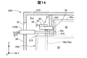
図13,図14を参照して、各インクタンク25Dの各電極ピン70a,70aに対する電気的導通性の検査と、大気取入部55を利用したインクタンク25Dにおける気密性の検査の方法の一例を説明する。図13は、インクタンク25Dの検査に用いられる検査装置200Dの構成を示す概略図である。図13には、タンクユニット20Dにおける貫通窓92近傍の部位も図示されている。図14は、検査装置200Dによって検査しているときの状態を示す模式図である。図14には、矢印Xの方向に見たときの回路ユニット27とインクタンク25Dの接続部位および大気取入部55が図示されている。   Referring to FIGS. 13 and 14, an example of a method for inspecting electrical continuity of each ink tank 25 </ b> D with respect to each electrode pin 70 a, 70 a and for inspecting airtightness in ink tank 25 </ b> D using atmospheric intake 55. explain. FIG. 13 is a schematic diagram showing the configuration of an inspection apparatus 200D used for inspection of the ink tank 25D. FIG. 13 also shows a portion near the through window 92 in the tank unit 20D. FIG. 14 is a schematic diagram showing a state when inspecting by the inspection apparatus 200D. FIG. 14 shows a connection site between the circuit unit 27 and the ink tank 25D and the air intake 55 when viewed in the direction of the arrow X.

第4実施形態における検査装置200Dは、以下に説明する点以外は、第1実施形態における検査装置200とほぼ同じである。検査装置200Dには、コネクター部210Dにノズル部213が追加されているとともに、本体部220Dに、チューブ202と、ポンプ部225と、圧力計測部226と、が追加されている(図13)。   The inspection apparatus 200D in the fourth embodiment is substantially the same as the inspection apparatus 200 in the first embodiment except for the points described below. In the inspection apparatus 200D, a nozzle part 213 is added to the connector part 210D, and a tube 202, a pump part 225, and a pressure measurement part 226 are added to the main body part 220D (FIG. 13).

ノズル部213は、チューブ202を介して、本体部220Dのポンプ部225に接続されており、ポンプ部225から送り出された高圧空気を先端開口214から噴射可能である。ポンプ部225は制御部223の制御下において、所定の回転数で駆動する。圧力計測部226は、チューブ202に取り付けられており、チューブ202内の気圧を計測する。圧力計測部226は、計測結果を表す信号を制御部223に送信する。   The nozzle part 213 is connected to the pump part 225 of the main body part 220 </ b> D via the tube 202, and the high-pressure air sent out from the pump part 225 can be injected from the tip opening 214. The pump unit 225 is driven at a predetermined rotation speed under the control of the control unit 223. The pressure measurement unit 226 is attached to the tube 202 and measures the atmospheric pressure in the tube 202. The pressure measurement unit 226 transmits a signal representing the measurement result to the control unit 223.

ノズル部213は、コネクター部210Dにおいて、一対のピン端子211,212と一体的に連結されている。ノズル部213は、各ピン端子211,212が対応する電極ピン70a,70bの後端部72a,72bに接触するときに、大気取入部55の貫通孔55hに先端開口が接続されるように構成されている(図14)。   The nozzle portion 213 is integrally connected to the pair of pin terminals 211 and 212 in the connector portion 210D. The nozzle portion 213 is configured such that the tip opening is connected to the through hole 55h of the air intake portion 55 when each pin terminal 211, 212 contacts the rear end portion 72a, 72b of the corresponding electrode pin 70a, 70b. (FIG. 14).

検査装置200Dを用いた大気取入部55に対する気密性の検査は、以下のようにおこなわれる。なお、検査装置200Dによる各電極ピン70a,70aに対する電気的導通性の検査の内容は、第1実施形態で説明したのとほぼ同じであるため、その説明は省略する。   The airtightness inspection for the air intake unit 55 using the inspection device 200D is performed as follows. In addition, since the content of the electrical continuity test for the electrode pins 70a and 70a by the test apparatus 200D is substantially the same as that described in the first embodiment, the description thereof is omitted.

コネクター部210Dが貫通窓92から挿入されて、各ピン端子211,212が対応する電極ピン70a,70bの後端部72a,72bに接触すると、ノズル部213の先端開口214が大気取入部55の貫通孔55hに先端開口が接続される(図14)。制御部223は、電流印加部221によって各電極ピン70a,70bに電流を印加するときに、同時に、ポンプ部225を駆動させて、ノズル部213から大気取入部55を介して大気導入部51へと高圧空気を送り出す。   When the connector portion 210D is inserted from the through window 92 and the pin terminals 211 and 212 come into contact with the rear end portions 72a and 72b of the corresponding electrode pins 70a and 70b, the front end opening 214 of the nozzle portion 213 becomes the air intake portion 55. The tip opening is connected to the through hole 55h (FIG. 14). When the current application unit 221 applies a current to the electrode pins 70 a and 70 b, the control unit 223 simultaneously drives the pump unit 225 from the nozzle unit 213 to the atmosphere introduction unit 51 via the atmosphere intake unit 55. And send out high-pressure air.

制御部223は、ポンプ部225を駆動させた後のチューブ202内の圧力値が所定の閾値未満であるときには、報知部224を介して、インクタンク25Dの気密性が確保されていない可能性があることをユーザーに報知する。なお、インクタンク25Dの気密性が低下していると、インクタンク25Dからのインクの供給性が低下する可能性がある。従って、このインクタンク25Dの気密性の検査は、インクタンク25Dにおけるインクの供給性に関する検査であると解釈できる。   When the pressure value in the tube 202 after driving the pump unit 225 is less than a predetermined threshold, the controller 223 may not ensure the airtightness of the ink tank 25D via the notification unit 224. Inform the user that there is. Note that if the airtightness of the ink tank 25D is lowered, the ink supply from the ink tank 25D may be lowered. Therefore, the air tightness inspection of the ink tank 25D can be interpreted as an inspection relating to ink supply in the ink tank 25D.

以上のように、第4実施形態のタンクユニット20Dによれば、貫通窓92を介して、インクタンク25Dにおける電気的導通性の検査と気密性の検査と、を簡易におこなうことができる。また、第4実施形態の検査装置200Dを用いれば、その両方の検査を同時におこなうことができる。その他に、第4実施形態のタンクユニット20Dおよびそれを備えるプリンターによれば、第1実施形態で説明したのと同様な種々の作用効果を奏することができる。   As described above, according to the tank unit 20D of the fourth embodiment, the electrical continuity test and the airtightness test in the ink tank 25D can be easily performed through the through window 92. Further, if the inspection apparatus 200D of the fourth embodiment is used, both inspections can be performed simultaneously. In addition, according to the tank unit 20D of the fourth embodiment and the printer including the same, various functions and effects similar to those described in the first embodiment can be achieved.

E.第5実施形態:
図15は、本発明の第5実施形態におけるタンクユニット20Eの構成を示す概略図である。図15には、タンクユニット20Eの背面の一部が、図13と同様に図示されている。第5実施形態のタンクユニット20Eは、以下に説明する点以外は、第4実施形態で説明したタンクユニット20Dとほぼ同じ構成を有している。第5実施形態のプリンターの構成は、タンクユニット20Eを備えている点以外は、第1実施形態のプリンター10(図1)とほぼ同じである。以下の説明および参照図では、第4実施形態で説明したのと同じ、または、対応する各構成部に対して、第4実施形態で用いたのと同じ符号が用いられている。
E. Fifth embodiment:
FIG. 15 is a schematic diagram showing a configuration of a tank unit 20E in the fifth embodiment of the present invention. In FIG. 15, a part of the back surface of the tank unit 20 </ b> E is illustrated as in FIG. 13. The tank unit 20E of the fifth embodiment has substantially the same configuration as the tank unit 20D described in the fourth embodiment, except for the points described below. The configuration of the printer of the fifth embodiment is substantially the same as that of the printer 10 (FIG. 1) of the first embodiment, except that the tank unit 20E is provided. In the following description and reference drawings, the same reference numerals as those used in the fourth embodiment are used for the same or corresponding components as those described in the fourth embodiment.

タンクユニット20Eでは、ケーシング部21Eの背面側全体が開口することによって背面開口93が形成されている。これによって、タンクユニット20Eは、印刷部30との連結状態が解除されたときに、各インクタンク25Dの第4面部44側の全体が、背面開口93を介して外部に露出する。第5実施形態では、第2実施形態と同様に、背面開口93が本発明における開口の下位概念に相当する。   In the tank unit 20E, a back opening 93 is formed by opening the entire back side of the casing portion 21E. As a result, the tank unit 20 </ b> E is exposed to the outside through the back surface opening 93 on the fourth surface 44 side of each ink tank 25 </ b> D when the connection state with the printing unit 30 is released. In the fifth embodiment, similarly to the second embodiment, the back surface opening 93 corresponds to a subordinate concept of the opening in the present invention.

第5実施形態のタンクユニット20Eによれば、背面開口93を介して、各インクタンク25Dの一対の電極ピン70a,70bに対する電気的導通性の検査を簡易におこなうことができる。また、大気取入部55を利用してインクタンク25Dの気密性の検査を簡易におこなうことができる。これらの検査には、第1実施形態や第4実施形態で説明した検査装置200,200Dを用いることができる。また、第5実施形態のタンクユニット20Dであれば、背面開口93の開口面積が第4実施形態の貫通窓92の開口面積よりも大きいため、ケーシング部21Eの外部からの各電極ピン70a,70bの後端部72a,72bおよび大気取入部55に対するアクセス性が高められている。その他に、第5実施形態のタンクユニット20Eおよびそれを備えるプリンターによれば、上記の各実施形態で説明したのと同様な種々の作用効果を奏することができる。   According to the tank unit 20E of the fifth embodiment, the electrical continuity test for the pair of electrode pins 70a and 70b of each ink tank 25D can be easily performed via the back surface opening 93. Further, the air tightness inspection of the ink tank 25D can be easily performed using the air intake portion 55. For these inspections, the inspection devices 200 and 200D described in the first embodiment and the fourth embodiment can be used. Further, in the tank unit 20D of the fifth embodiment, since the opening area of the back opening 93 is larger than the opening area of the through window 92 of the fourth embodiment, the electrode pins 70a and 70b from the outside of the casing portion 21E. Accessibility to the rear end portions 72a and 72b and the air intake portion 55 is enhanced. In addition, according to the tank unit 20E of the fifth embodiment and the printer including the same, various functions and effects similar to those described in the above embodiments can be achieved.

F.第6実施形態:
図16は、本発明の第6実施形態におけるタンクユニット20Fの構成を示す概略断面図である。図16には、貫通窓92の近傍部位を、矢印Xの方向に垂直な切断面で切断したときの断面が図示されている。第6実施形態のタンクユニット20Fの構成は、以下に説明する点以外は、第1実施形態のタンクユニット20Aとほぼ同じである。第6実施形態のプリンターの構成は、タンクユニット20Fを備えている点以外は、第1実施形態のプリンター10(図1)とほぼ同じである。以下の説明および参照図では、第1実施形態で説明したのと同じ、または、対応する各構成部に対して、第1実施形態で用いたのと同じ符号が用いられている。
F. Sixth embodiment:
FIG. 16 is a schematic cross-sectional view showing a configuration of a tank unit 20F in the sixth embodiment of the present invention. FIG. 16 shows a cross section when the vicinity of the through window 92 is cut by a cutting plane perpendicular to the direction of the arrow X. The configuration of the tank unit 20F of the sixth embodiment is substantially the same as the tank unit 20A of the first embodiment except for the points described below. The configuration of the printer of the sixth embodiment is substantially the same as that of the printer 10 (FIG. 1) of the first embodiment except that the tank unit 20F is provided. In the following description and reference drawings, the same reference numerals as those used in the first embodiment are used for the same or corresponding components described in the first embodiment.

第6実施形態のタンクユニット20Fでは、背面壁部90の貫通窓92が、封止部材94によって封止されている。封止部材94は、例えば、樹脂製のフィルム部材によって構成され、その外周縁部が貫通窓92の内周縁部に溶着される。タンクユニット20Fでは、封止部材94を貫通窓92から取り外すか、封止部材94を破ることによって、インクタンク25Aの各電極ピン70a,70bに対する電気的導通性の検査をおこなうことができる。第6実施形態のタンクユニット20Fによれば、印刷部30との連結状態が解除された状態においても、貫通窓92からの異物の進入などが、封止部材94によって抑制され、タンクユニット20Fの保護性が高められている。   In the tank unit 20 </ b> F of the sixth embodiment, the through window 92 of the back wall 90 is sealed by the sealing member 94. The sealing member 94 is made of, for example, a resin film member, and an outer peripheral edge thereof is welded to an inner peripheral edge of the through window 92. In the tank unit 20F, the electrical continuity test can be performed on the electrode pins 70a and 70b of the ink tank 25A by removing the sealing member 94 from the through window 92 or breaking the sealing member 94. According to the tank unit 20F of the sixth embodiment, even when the connection state with the printing unit 30 is released, the entry of foreign matter from the through window 92 is suppressed by the sealing member 94, and the tank unit 20F Protection is enhanced.

図17,図18を参照して、封止部材94の他の構成例を説明する。図17,図18にはそれぞれ、異なる構成の封止部材94a,94bが取り付けられたタンクユニット20Fの概略断面が、図16と同様に図示されている。封止部材94aは、貫通窓92に嵌め込まれる樹脂製のキャップ部材として構成されている(図17)。封止部材94aは、貫通窓92に嵌合するように取り付けられるため、貫通窓92に対する着脱性が高められる。封止部材94bは、樹脂製の板状部材などによって構成されており、ヒンジ機構95によって、貫通窓92を開閉可能なように、背面壁部90に連結されている。封止部材94bであれば、貫通窓92を介した電極ピン70a,70bに対するアクセスが簡易化される。   With reference to FIG. 17, FIG. 18, the other structural example of the sealing member 94 is demonstrated. FIGS. 17 and 18 each show a schematic cross section of a tank unit 20F to which sealing members 94a and 94b having different configurations are attached, as in FIG. The sealing member 94a is configured as a resin cap member fitted into the through window 92 (FIG. 17). Since the sealing member 94a is attached so as to fit into the through window 92, the detachability with respect to the through window 92 is improved. The sealing member 94 b is configured by a resin plate member or the like, and is connected to the back wall 90 by a hinge mechanism 95 so that the through window 92 can be opened and closed. With the sealing member 94b, access to the electrode pins 70a and 70b through the through window 92 is simplified.

以上のように、第6実施形態のタンクユニット20Fによれば、封止部材94,94a,94bによって、タンクユニット20F内部への異物の侵入などが抑制される。その他に、第6実施形態のタンクユニット20Fおよびそれを備えるプリンターによれば、第1実施形態で説明したのと同様な種々の作用効果を奏することができる。なお、第6実施形態における封止部材94,94a,94bの構成は、第3実施形態のタンクユニット20Cや第4実施形態のタンクユニット20Dの貫通窓92に対して適用されても良い。また、第2実施形態のタンクユニット20Bや第5実施形態のタンクユニット20Eに対して、背面開口93の全体または一部を封止するように、封止部材94,94a,94bが取り付けられても良い。   As described above, according to the tank unit 20F of the sixth embodiment, entry of foreign matter into the tank unit 20F is suppressed by the sealing members 94, 94a, 94b. In addition, according to the tank unit 20F of the sixth embodiment and the printer including the same, various functions and effects similar to those described in the first embodiment can be achieved. In addition, the structure of the sealing members 94, 94a, and 94b in the sixth embodiment may be applied to the through window 92 of the tank unit 20C of the third embodiment and the tank unit 20D of the fourth embodiment. Further, sealing members 94, 94a, 94b are attached to the tank unit 20B of the second embodiment and the tank unit 20E of the fifth embodiment so as to seal all or a part of the back opening 93. Also good.

G.第7実施形態:
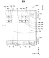
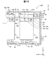
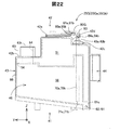
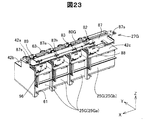
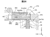
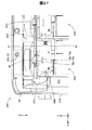
図19〜図26を参照して、本発明の第7実施形態におけるプリンター10Gおよびタンクユニット20Gの構成を説明する。図19は、第7実施形態のプリンター10Gの構成の一部を示す概略斜視図である。図19では、第7実施形態のタンクユニット20Gの蓋部23が閉じられた状態が図示されている。図20は、蓋部23が開かれた状態の第7実施形態のタンクユニット20Gを示す概略斜視図である。図21は、タンクユニット20Gの背面側を示す概略斜視図である。図22は、第7実施形態のタンクユニット20Gが備えるインクタンク25Gを矢印Xの逆方向に見たときの概略側面図である。図22には、インクタンク25Gの一部の内部構造が破線によって模式的に図示されている。図22では、第7実施形態における基板部80Gが接続された状態が図示されている。図23は、インクタンク25Gに回路ユニット27Gが取り付けられている状態を示す概略斜視図であり、図21からケーシング部21Gを取り除いた図に相当する。図24は、第7実施形態のインクタンク25Gから一対の電極ピン70a,70bを分離するとともに、第7実施形態の回路ユニット27Gを分解した状態を示す概略分解斜視図である。図25は、タンクユニット20Gの背面の一部を示す概略背面図である。図26は、図25に示すA−A切断におけるタンクユニット20Gの概略断面図である。図19〜図26では、チューブ26およびケーブル配線28の図示は便宜上、省略されている。
G. Seventh embodiment:
The configuration of the printer 10G and the tank unit 20G in the seventh embodiment of the present invention will be described with reference to FIGS. FIG. 19 is a schematic perspective view illustrating a part of the configuration of the printer 10G according to the seventh embodiment. FIG. 19 illustrates a state where the lid portion 23 of the tank unit 20G of the seventh embodiment is closed. FIG. 20 is a schematic perspective view showing the tank unit 20G of the seventh embodiment in a state where the lid portion 23 is opened. FIG. 21 is a schematic perspective view showing the back side of the tank unit 20G. FIG. 22 is a schematic side view of the ink tank 25G provided in the tank unit 20G of the seventh embodiment when viewed in the direction opposite to the arrow X. In FIG. 22, a part of the internal structure of the ink tank 25G is schematically shown by a broken line. FIG. 22 illustrates a state where the substrate unit 80G in the seventh embodiment is connected. FIG. 23 is a schematic perspective view showing a state where the circuit unit 27G is attached to the ink tank 25G, and corresponds to a view in which the casing portion 21G is removed from FIG. FIG. 24 is a schematic exploded perspective view showing a state where the pair of electrode pins 70a and 70b is separated from the ink tank 25G of the seventh embodiment and the circuit unit 27G of the seventh embodiment is disassembled. FIG. 25 is a schematic rear view showing a part of the rear surface of the tank unit 20G. FIG. 26 is a schematic cross-sectional view of the tank unit 20G taken along the line AA shown in FIG. 19 to 26, the tube 26 and the cable wiring 28 are not shown for convenience.

第7実施形態のプリンター10Gは、第7実施形態のタンクユニット20Gを備えている点以外は、第1実施形態のプリンター10(図1)とほぼ同じである。第7実施形態のタンクユニット20Gは、以下に説明する点以外は、第5実施形態のタンクユニット20Eの構成と同様である。以下の説明および参照図においては、上記の各実施形態で説明したのと同じ、または、対応する構成部に対して、上記の各実施形態で用いたのと同じ符号が用いられている。   The printer 10G of the seventh embodiment is almost the same as the printer 10 (FIG. 1) of the first embodiment except that the printer 10G of the seventh embodiment includes the tank unit 20G of the seventh embodiment. The tank unit 20G of the seventh embodiment is the same as the configuration of the tank unit 20E of the fifth embodiment except for the points described below. In the following description and reference drawings, the same reference numerals as those used in the above embodiments are used for the same or corresponding components as those described in the above embodiments.

第7実施形態のタンクユニット20Gのケーシング部21Gは、樹脂製の中空箱体として構成されている(図19〜図21)。第7実施形態のタンクユニット20Gは、ケーシング部21Gの内部空間21sに、複数のインクタンク25Gが、矢印Xの方向に一列に配列された状態で収容されている。複数のインクタンク25Gには、インク容量が異なる2種類のインクタンク25Ga,25Gbが含まれる。タンクユニット20Gは、3つの第1インクタンク25Gaと、1つの第2インクタンク25Gbと、を収容している。第2インクタンク25Gbは、矢印Xの方向における幅が第1インクタンク25Gaよりも大きいことによって、インク容量が第1インクタンク25Gaよりも大きくなっている点以外は、第1インクタンク25Gaとほぼ同じ構成を有している。以下では、特に断らない限り、2種類のインクタンク25Ga,25Gbを区別することなく、インクタンク25Gとして説明する。   The casing part 21G of the tank unit 20G of the seventh embodiment is configured as a resin hollow box (FIGS. 19 to 21). In the tank unit 20G of the seventh embodiment, a plurality of ink tanks 25G are accommodated in the internal space 21s of the casing portion 21G in a state of being arranged in a line in the direction of the arrow X. The plurality of ink tanks 25G include two types of ink tanks 25Ga and 25Gb having different ink capacities. The tank unit 20G accommodates three first ink tanks 25Ga and one second ink tank 25Gb. The second ink tank 25Gb is substantially the same as the first ink tank 25Ga except that the width in the direction of the arrow X is larger than that of the first ink tank 25Ga and the ink capacity is larger than that of the first ink tank 25Ga. It has the same configuration. In the following description, the ink tank 25G will be described without distinguishing between the two types of ink tanks 25Ga and 25Gb unless otherwise specified.

ケーシング部21Gの背面には、背面側の全体が開口することによって背面開口93が形成されている(図21)。タンクユニット20Gでは、各インクタンク25Gの第4面部44側が背面開口93から露出している。ケーシング部21Gの背面には、連結部22として、複数の係合爪部22cと、複数のネジ止め部22sと、が設けられている。各係合爪部22cは、背面開口93の下側において矢印Yの方向に突出している。各係合爪部22cは、印刷部30のケーシング部31(図19)に設けられている被係合穴(図示は省略)に係合する。各ネジ止め部22sは、背面開口93の上側と下側とにおいて矢印Yの方向に突出している(図21)。ケーシング部21Gは、正面側から各ネジ止め部22sの内部に挿入されるネジ(図示は省略)によって、ケーシング部31(図19)の側面にネジ止めされる。   A back surface opening 93 is formed on the back surface of the casing portion 21G by opening the entire back surface side (FIG. 21). In the tank unit 20G, the fourth surface 44 side of each ink tank 25G is exposed from the back surface opening 93. A plurality of engaging claw portions 22c and a plurality of screwing portions 22s are provided as the connecting portion 22 on the back surface of the casing portion 21G. Each engaging claw portion 22 c protrudes in the direction of arrow Y below the back surface opening 93. Each engaging claw portion 22c engages with an engaged hole (not shown) provided in the casing portion 31 (FIG. 19) of the printing portion 30. Each screwing portion 22s protrudes in the direction of the arrow Y on the upper side and the lower side of the back surface opening 93 (FIG. 21). The casing part 21G is screwed to the side surface of the casing part 31 (FIG. 19) by screws (not shown) inserted into the screwing parts 22s from the front side.

タンクユニット20Gのケーシング部21Gには、各インクタンク25Gの第3面部43と対向する正面側の壁部に、窓部29が設けられている(図19,図20)。ユーザーは、窓部29を介して、各インクタンク25Gに収容されているインクINの液面の位置を視認することができる。タンクユニット20Gでは、ケーシング部21Gの蓋部23を開くと、各インクタンク25Gのインク注入部63が外部に露出する(図20)。ユーザーは、インク注入部63からキャップ部材65を取り外すことによって、各インクタンク25GにインクINを補充することができる。   The casing portion 21G of the tank unit 20G is provided with a window portion 29 on the front wall portion facing the third surface portion 43 of each ink tank 25G (FIGS. 19 and 20). The user can visually recognize the position of the liquid level of the ink IN stored in each ink tank 25G through the window portion 29. In the tank unit 20G, when the lid part 23 of the casing part 21G is opened, the ink injection part 63 of each ink tank 25G is exposed to the outside (FIG. 20). The user can replenish the ink IN to each ink tank 25G by removing the cap member 65 from the ink injection portion 63.

インクタンク25G(図22)は、第2面部42に、それぞれ高さ位置が異なる3つの上面部42a〜42cを有している。第1上面部42aは、最も高い位置にあり、前後方向において、第2上面部42bと第3上面部42cとの間に位置している。第2上面部42bは第3面部43側に位置しており、第3上面部42cは第4面部44側に位置している。第3上面部42cは、第2上面部42bよりも高い位置にある。第2上面部42bには、インク注入部63が設けられている。   The ink tank 25G (FIG. 22) has three upper surface portions 42a to 42c on the second surface portion 42, each having a different height position. The first upper surface portion 42a is at the highest position, and is positioned between the second upper surface portion 42b and the third upper surface portion 42c in the front-rear direction. The second upper surface portion 42b is located on the third surface portion 43 side, and the third upper surface portion 42c is located on the fourth surface portion 44 side. The third upper surface portion 42c is located higher than the second upper surface portion 42b. An ink injection part 63 is provided on the second upper surface part 42b.

第3上面部42cには、一対の電極ピン70a,70bが、以下のように取り付けられている。第3上面部42cには、第1円筒部68aおよび第2円筒部68bが上方に突出するように設けられている(図24)。第1円筒部68aおよび第2円筒部68bは、矢印Xの方向に隣り合って配列されている。第1電極ピン70aは、第1円筒部68aの貫通孔に挿入され、第2電極ピン70bは、第2円筒部68bの貫通孔に挿入される。各電極ピン70a,70bの後端部72a,72bは、インク注入部63の上端部63tよりも高い位置であって、第1上面部42aよりも低い位置に位置している(図22)。   A pair of electrode pins 70a and 70b are attached to the third upper surface portion 42c as follows. A first cylindrical portion 68a and a second cylindrical portion 68b are provided on the third upper surface portion 42c so as to protrude upward (FIG. 24). The first cylindrical portion 68a and the second cylindrical portion 68b are arranged adjacent to each other in the direction of the arrow X. The first electrode pin 70a is inserted into the through hole of the first cylindrical portion 68a, and the second electrode pin 70b is inserted into the through hole of the second cylindrical portion 68b. The rear end portions 72a and 72b of the electrode pins 70a and 70b are positioned higher than the upper end portion 63t of the ink injection portion 63 and are positioned lower than the first upper surface portion 42a (FIG. 22).

インクタンク25G(図22)では、大気導入部51は、各上面部42a〜42cの下側において、矢印Yの方向のほぼ全域にわたって形成されている。また、大気導入部51は、インク収容部50の第4面部44側において、インク供給部61との接続部位61cまで延びている。なお、大気導入部51は、第2上面部42bおよび第3上面部42cの下方では、インク注入部63の貫通孔64および一対の電極ピン70a,70bと干渉しないように、それらの配置領域よりも第6面部46側に位置している。   In the ink tank 25G (FIG. 22), the air introduction part 51 is formed over substantially the entire region in the direction of the arrow Y below the upper surface parts 42a to 42c. The air introduction part 51 extends to the connection part 61 c with the ink supply part 61 on the fourth surface part 44 side of the ink storage part 50. Note that the air introduction portion 51 is located below the second upper surface portion 42b and the third upper surface portion 42c so as not to interfere with the through hole 64 of the ink injection portion 63 and the pair of electrode pins 70a and 70b. Is also located on the sixth surface portion 46 side.

ここで、第1上面部42aと第3上面部42cとの間には、矢印Yの逆方向に向く段差面42dが形成されている(図22)。段差面42dには、第4実施形態で説明したのと同様な大気取入部55が、矢印Yの逆方向に突出するように設けられている(図24)。大気取入部55は、矢印Yの方向に見たときに、各電極ピン70a,70bの後端部72a,72bの右側に位置している。また、大気取入部55は、矢印Yの方向に見たときに、各電極ピン70a,70bの後端部72a,72bと同様に、インク注入部63の上端部63tよりも上方に位置している。   Here, a step surface 42d is formed between the first upper surface portion 42a and the third upper surface portion 42c so as to face in the direction opposite to the arrow Y (FIG. 22). An air intake 55 similar to that described in the fourth embodiment is provided on the step surface 42d so as to protrude in the opposite direction of the arrow Y (FIG. 24). When viewed in the direction of arrow Y, the air intake portion 55 is located on the right side of the rear end portions 72a and 72b of the electrode pins 70a and 70b. Further, when viewed in the direction of the arrow Y, the air intake portion 55 is positioned above the upper end portion 63t of the ink injection portion 63, like the rear end portions 72a and 72b of the electrode pins 70a and 70b. Yes.

このように、インクタンク25Dでは、大気取入部55と、各電極ピン70a,70bの後端部72a,72bとが背面側における上方の領域にまとめられている。これによって、大気取入部55および各電極ピン70a,70bの後端部72a,72bに対するアクセス性が高められており、タンクユニット20Gにおけるインクタンク25Gに対する検査性やメンテナンス性が高められている。   As described above, in the ink tank 25D, the air intake portion 55 and the rear end portions 72a and 72b of the electrode pins 70a and 70b are grouped in an upper region on the back side. As a result, the accessibility to the air intake portion 55 and the rear end portions 72a and 72b of the electrode pins 70a and 70b is enhanced, and the inspectability and maintainability of the ink tank 25G in the tank unit 20G are enhanced.

タンクユニット20Gでは、各インクタンク25Gの第4面部44側の上方に、各インクタンク25Gに電気的に接続される単一の回路ユニット27Gが配置されている(図21,図23)。回路ユニット27Gは、基板部80Gと、複数のコネクターユニット83と、支持部材87と、を備えている(図24)。   In the tank unit 20G, a single circuit unit 27G electrically connected to each ink tank 25G is disposed above the fourth surface portion 44 side of each ink tank 25G (FIGS. 21 and 23). The circuit unit 27G includes a board portion 80G, a plurality of connector units 83, and a support member 87 (FIG. 24).

基板部80Gは、タンクユニット20Gにおいて、各インクタンク25Gの電極ピン70a,70bに電気的に接続可能なように、矢印Xの方向に延在している(図23,図24)。基板部80Gの下側の基板面には、各インクタンク25Gの一対の電極ピン70a,70bに対応して設けられた複数組の一対の基板端子81a,81bが設けられている(図22)。基板部80Gの上側の基板面には、矢印Xの逆方向側の端部に寄った位置に単一のケーブル接続部82が設けられている(図23,図24)。各基板端子81a,81bとケーブル接続部82とは、基板部80Gの形成されている配線パターン(図示は省略)を介して接続されている。   The substrate unit 80G extends in the direction of the arrow X so that it can be electrically connected to the electrode pins 70a and 70b of each ink tank 25G in the tank unit 20G (FIGS. 23 and 24). A plurality of pairs of substrate terminals 81a and 81b provided corresponding to the pair of electrode pins 70a and 70b of each ink tank 25G are provided on the lower substrate surface of the substrate portion 80G (FIG. 22). . A single cable connection portion 82 is provided on the upper substrate surface of the substrate portion 80G at a position close to the end portion on the opposite side of the arrow X (FIGS. 23 and 24). Each board terminal 81a, 81b and the cable connection part 82 are connected via the wiring pattern (illustration omitted) in which the board part 80G is formed.

コネクターユニット83は、基板部80Gと各インクタンク25Gとの間の電気的接続を仲介可能なように、基板部80Gの下方において、複数のインクタンク25Gのうちの対応するひとつの上にそれぞれ配置される(図24)。コネクターユニット83は、略板形状を有しており、一対の第1端子84a,84bと、一対の第2端子85a,85bと、を有している(図24,図26)。一対の第2端子85a,85bは、一対の基板端子81a,81bに電気的に接触する。一対の第1端子84a,84bは、各電極ピン70a,70bの後端部72a,72bに電気的に接触する。   The connector unit 83 is disposed on the corresponding one of the plurality of ink tanks 25G below the substrate unit 80G so as to mediate electrical connection between the substrate unit 80G and each ink tank 25G. (FIG. 24). The connector unit 83 has a substantially plate shape, and has a pair of first terminals 84a and 84b and a pair of second terminals 85a and 85b (FIGS. 24 and 26). The pair of second terminals 85a and 85b are in electrical contact with the pair of substrate terminals 81a and 81b. The pair of first terminals 84a and 84b are in electrical contact with the rear ends 72a and 72b of the electrode pins 70a and 70b.

第1端子84aと第2端子85aとは第1板状導電部86aを介して連結されている(図26)。また、第1端子84bと第2端子85bとは、第2板状導電部86bを介して連結されている。各板状導電部86a,86bは、板バネ状に折れ曲がっていることによって、各コネクターユニット83の厚み方向に弾性変形可能に構成されている。第1端子84a,84bおよび第2端子85a,85bは、各板状導電部86a,86bによってコネクターユニット83の厚み方向に付勢されている。これによって、コネクターユニット83では、各電極ピン70a,70bの後端部72a,72bに対する基板端子81a,81bの接触性が高められている。また、基板部80Gが、各電極ピン70a,70bから受ける押圧力によって撓み変形してしまうことが抑制されている。   The first terminal 84a and the second terminal 85a are connected via a first plate-like conductive portion 86a (FIG. 26). Further, the first terminal 84b and the second terminal 85b are connected via the second plate-like conductive portion 86b. Each plate-like conductive portion 86a, 86b is configured to be elastically deformable in the thickness direction of each connector unit 83 by being bent into a leaf spring shape. The first terminals 84a and 84b and the second terminals 85a and 85b are urged in the thickness direction of the connector unit 83 by the plate-like conductive portions 86a and 86b. Thereby, in the connector unit 83, the contact of the board terminals 81a and 81b with respect to the rear ends 72a and 72b of the electrode pins 70a and 70b is enhanced. Further, the substrate portion 80G is restrained from being bent and deformed by the pressing force received from the electrode pins 70a and 70b.

支持部材87は、矢印Xの方向に延伸している板状の部材であり、各インクタンク25Gの上方に架設される。支持部材87の矢印Xの方向における長さは、基板部80Gの矢印Xの方向における長さよりも長い。支持部材87は、例えば、ナイロンやポリプロピレンなどの合成樹脂によって構成される。基板部80Gおよび複数のコネクターユニット83は、支持部材87の上に固定されて支持される。支持部材87には、基板部80Gの外縁部に係り合って基板部80Gの移動を規制する係合爪87eや、コネクターユニット83が嵌合する嵌合穴87hが設けられている。   The support member 87 is a plate-like member extending in the direction of the arrow X, and is installed above each ink tank 25G. The length of the support member 87 in the direction of the arrow X is longer than the length of the substrate unit 80G in the direction of the arrow X. The support member 87 is made of, for example, a synthetic resin such as nylon or polypropylene. The board portion 80G and the plurality of connector units 83 are fixed and supported on the support member 87. The support member 87 is provided with an engaging claw 87e that engages with the outer edge portion of the board portion 80G and restricts the movement of the board portion 80G, and a fitting hole 87h into which the connector unit 83 is fitted.

支持部材87は、矢印Xの方向における両端に設けられたネジ止め部87sにおいて、ケーシング部21Gの上方の壁部にネジ止めされて、ケーシング部21Gに固定される(図21,図24,図25)。タンクユニット20Gでは、支持部材87によって、基板部80Gの撓み変形などが抑制されている。また、支持部材87によって複数のコネクターユニット83を対応するインクタンク25Gの各電極ピン70a,70bに一度に接続させることができ、回路ユニット27Gの接続性が高められている。   The support member 87 is fixed to the casing portion 21G by being screwed to the upper wall portion of the casing portion 21G at the screwing portions 87s provided at both ends in the direction of the arrow X (FIGS. 21, 24, and 24). 25). In the tank unit 20G, the support member 87 suppresses bending deformation of the substrate unit 80G. In addition, the plurality of connector units 83 can be connected to the corresponding electrode pins 70a and 70b of the corresponding ink tank 25G by the support member 87 at a time, and the connectivity of the circuit unit 27G is enhanced.

支持部材87は、各インクタンク25Gの第1上面部42aに、ネジ89によって固定される(図23)。これによって、各インクタンク25Gは、支持部材87を介して、ケーシング部21Gに固定される。   The support member 87 is fixed to the first upper surface portion 42a of each ink tank 25G with a screw 89 (FIG. 23). Accordingly, each ink tank 25G is fixed to the casing portion 21G via the support member 87.

支持部材87の背面側の端部には、複数の保護壁部88が形成されている(図23,図24)。各保護壁部88は、インクタンク25Gのうちのひとつと対向する位置において鉛直方向に垂下するように形成されている。各保護壁部88は、タンクユニット20Gを矢印Yの方向に見たときに、インクタンク25Gの各電極ピン70a,70bの後端部72a,72bと重なる位置に配置される(図25,図26)。各保護壁部88は、タンクユニット20Gが印刷部30に連結されたときに、印刷部30と各電極ピン70a,70bの後端部72a,72bとの間に位置する。タンクユニット20Gでは、各保護壁部88によって、回路ユニット27Gと各電極ピン70a,70bとの接続部位が、異物の侵入などから保護される。   A plurality of protective wall portions 88 are formed at the back end of the support member 87 (FIGS. 23 and 24). Each protection wall portion 88 is formed so as to hang in the vertical direction at a position facing one of the ink tanks 25G. Each protective wall portion 88 is disposed at a position overlapping the rear end portions 72a and 72b of the electrode pins 70a and 70b of the ink tank 25G when the tank unit 20G is viewed in the direction of arrow Y (FIGS. 25 and 25). 26). Each protective wall 88 is located between the printing unit 30 and the rear end portions 72a and 72b of the electrode pins 70a and 70b when the tank unit 20G is connected to the printing unit 30. In the tank unit 20G, the connection portions between the circuit unit 27G and the electrode pins 70a and 70b are protected from intrusion of foreign matter by the protective wall portions 88.

各保護壁部88には貫通窓96が設けられている(図25,図26)。貫通窓96は、その開口方向である矢印Yの方向に見たときに、各電極ピン70a,70bの後端部72a,72bの一部と重なる位置に形成されている(図25)。タンクユニット20Gでは、各電極ピン70a,70bの後端部72a,72bの一部は、ケーシング部21Gの背面開口93と、支持部材87の貫通窓96と、を介して外部に露出する。第5実施形態では、背面開口93と貫通窓96とはそれぞれ、本発明における開口の下位概念に相当する。   Each protective wall portion 88 is provided with a through window 96 (FIGS. 25 and 26). The through window 96 is formed at a position that overlaps a part of the rear end portions 72a and 72b of the electrode pins 70a and 70b when viewed in the direction of the arrow Y that is the opening direction (FIG. 25). In the tank unit 20G, a part of the rear end portions 72a and 72b of the electrode pins 70a and 70b are exposed to the outside through the back surface opening 93 of the casing portion 21G and the through window 96 of the support member 87. In the fifth embodiment, each of the back opening 93 and the through window 96 corresponds to a subordinate concept of the opening in the present invention.

タンクユニット20Gによれば、貫通窓96を介して、各インクタンク25Gがケーシング部21G内に固定された状態のまま、各インクタンク25Gの電極ピン70a,70bに対する電気的導通性の検査を簡易におこなうことができる。また、タンクユニット20Gであれば、当該電気的導通性の検査を、第1実施形態で説明した検査装置200(図5,図6)を用いておこなうことができる。   According to the tank unit 20G, the electrical continuity test with respect to the electrode pins 70a and 70b of each ink tank 25G can be easily performed while the respective ink tanks 25G are fixed in the casing portion 21G through the through windows 96. Can be done. Moreover, if it is the tank unit 20G, the said electrical continuity test | inspection can be performed using the test | inspection apparatus 200 (FIG. 5, FIG. 6) demonstrated in 1st Embodiment.

加えて、タンクユニット20Gでは、貫通窓96の開口方向に見たときに、コネクターユニット83と各電極ピン70a,70bとの接触部位は、貫通窓96の外に位置する。すなわち、各電極ピン70a,70bの後端部72a,72bのうち、コネクターユニット83の第1端子84a,84bに接触している部位以外の部位が貫通窓96内に位置している。これによって、コネクターユニット83と各電極ピン70a,70bとの接触部位が外部に露出しにくくなっており、当該接触部位の保護性が高められている。   In addition, in the tank unit 20 </ b> G, when viewed in the opening direction of the through window 96, the contact portion between the connector unit 83 and the electrode pins 70 a and 70 b is located outside the through window 96. That is, portions of the rear end portions 72 a and 72 b of the electrode pins 70 a and 70 b other than the portions in contact with the first terminals 84 a and 84 b of the connector unit 83 are located in the through window 96. As a result, contact portions between the connector unit 83 and the electrode pins 70a and 70b are hardly exposed to the outside, and the protection of the contact portions is enhanced.

タンクユニット20Gを矢印Yの方向に見たときに、各インクタンク25Gの大気取入部55は、保護壁部88から離間した位置に位置しており、保護壁部88とは重なり合わない位置に位置している(図25)。そのため、タンクユニット20Gによれば、印刷部30との連結が解除された状態において背面開口93から露出する大気取入部55を利用して、各インクタンク25Gの気密性の検査を簡易におこなうことができる。また、タンクユニット20Gであれば、矢印Yの方向に見たときに、各電極ピン70a,70bの後端部72a,72bと大気取入部55とが矢印Xの方向に配列された状態になる。また、貫通窓96と大気取入部55とが矢印Xの方向に配列された状態になる。従って、第4実施形態で説明した検査装置200D(図13,図14)を用いて、各インクタンク25Gに対する電気的導通性の検査と気密性の検査とを同時におこなうことができる。   When the tank unit 20G is viewed in the direction of the arrow Y, the air intake portion 55 of each ink tank 25G is located at a position separated from the protective wall portion 88, and is not overlapped with the protective wall portion 88. Is located (FIG. 25). Therefore, according to the tank unit 20G, the air tightness inspection of each ink tank 25G can be easily performed by using the air intake part 55 exposed from the back surface opening 93 in the state where the connection with the printing part 30 is released. Can do. Further, in the tank unit 20G, when viewed in the direction of the arrow Y, the rear end portions 72a and 72b of the electrode pins 70a and 70b and the air intake portion 55 are arranged in the direction of the arrow X. . Further, the through windows 96 and the air intake portions 55 are arranged in the direction of the arrow X. Therefore, using the inspection apparatus 200D (FIGS. 13 and 14) described in the fourth embodiment, the electrical continuity inspection and the air tightness inspection for each ink tank 25G can be performed simultaneously.

以上のように、第7実施形態のタンクユニット20Gによれば、各インクタンク25Gの各電極ピン70a,70bの電気的導通性の検査や、各インクタンク25Gの気密性の検査を簡易におこなうことができる。その他に、第7実施形態のタンクユニット20Gおよびプリンター10Gによれば、上記各実施形態で説明したのと同様な種々の作用効果を奏することができる。   As described above, according to the tank unit 20G of the seventh embodiment, the electrical continuity inspection of each electrode pin 70a, 70b of each ink tank 25G and the airtightness inspection of each ink tank 25G are easily performed. be able to. In addition, according to the tank unit 20G and the printer 10G of the seventh embodiment, various functions and effects similar to those described in the above embodiments can be achieved.

H.第8実施形態:
図27は、本発明の第8実施形態におけるタンクユニット20Hの背面の一部を示す概略背面図である。第8実施形態のタンクユニット20Hの構成は、支持部材87Hの保護壁部88Hの構成が異なっている点以外は、第7実施形態のタンクユニット20Gとほぼ同じである。第8実施形態のプリンターは、タンクユニット20Hを備えている点以外は、第7実施形態のプリンター10G(図19)とほぼ同じである。以下の説明および参照図においては、上記の第7実施形態で説明したのと同じ、または、対応する構成部に対して、上記の第7実施形態で用いたのと同じ符号が用いられている。
H. Eighth embodiment:
FIG. 27 is a schematic rear view showing part of the rear surface of the tank unit 20H according to the eighth embodiment of the present invention. The configuration of the tank unit 20H of the eighth embodiment is substantially the same as the tank unit 20G of the seventh embodiment except that the configuration of the protective wall portion 88H of the support member 87H is different. The printer of the eighth embodiment is substantially the same as the printer 10G (FIG. 19) of the seventh embodiment except that it includes a tank unit 20H. In the following description and reference drawings, the same reference numerals as those used in the seventh embodiment are used for the same or corresponding components as those described in the seventh embodiment. .

第8実施形態のタンクユニット20Hでは、保護壁部88Hの矢印Xの方向における幅は、第7実施形態の保護壁部88よりも大きい。保護壁部88Hには、各電極ピン70a,70bの後端部72a,72bが露出する貫通窓96(以下、「第1貫通窓96」と呼ぶ。)に加えて、大気取入部55が露出する第2貫通窓97が設けられている。   In the tank unit 20H of the eighth embodiment, the width of the protective wall 88H in the direction of the arrow X is larger than that of the protective wall 88 of the seventh embodiment. In addition to the through window 96 in which the rear ends 72a and 72b of the electrode pins 70a and 70b are exposed (hereinafter referred to as “first through window 96”), the air intake 55 is exposed in the protective wall 88H. A second through window 97 is provided.

第8実施形態のタンクユニット20Hによれば、第7実施形態のタンクユニット20Gと同様に、各インクタンク25Gの各電極ピン70a,70bの電気的導通性の検査や、各インクタンク25Gの気密性の検査を簡易におこなうことができる。また、第8実施形態のタンクユニット20Hによれば、保護壁部88の面積が大きい分だけ、各インクタンク25Gに対する保護性が高められている。その他に、第7実施形態のタンクユニット20Hおよびそれを備えるプリンターによれば、上記各実施形態で説明したのと同様な種々の作用効果を奏することができる。   According to the tank unit 20H of the eighth embodiment, similarly to the tank unit 20G of the seventh embodiment, the electrical continuity test of each electrode pin 70a, 70b of each ink tank 25G and the airtightness of each ink tank 25G are performed. The sex test can be performed easily. Further, according to the tank unit 20H of the eighth embodiment, the protection for each ink tank 25G is enhanced by the amount of the area of the protection wall portion 88 being large. In addition, according to the tank unit 20H of the seventh embodiment and the printer including the same, various functions and effects similar to those described in the above embodiments can be achieved.

図28,図29を参照して、第8実施形態のタンクユニット20Hの他の構成例を説明する。図28,図29にはそれぞれ、図27と同様に、タンクユニット20Hの背面の一部が図示されている。保護壁部88Hには、第1貫通窓96と第2貫通窓97とが一体化された貫通窓98が設けられても良い(図28)。また、保護壁部88Hには、第1貫通窓96の代わりに、第1電極ピン70aの後端部72aに対応する位置に形成された貫通窓96aと、第2電極ピン70bの後端部72bに対応する位置に形成された貫通窓96bと、が設けられても良い(図29)。これらの構成であっても、上述したのと同様な作用効果を奏することができる。   With reference to FIG. 28 and FIG. 29, the other structural example of the tank unit 20H of 8th Embodiment is demonstrated. Each of FIGS. 28 and 29 shows a part of the rear surface of the tank unit 20H as in FIG. The protective wall 88H may be provided with a through window 98 in which the first through window 96 and the second through window 97 are integrated (FIG. 28). Further, instead of the first through window 96, the protective wall 88H has a through window 96a formed at a position corresponding to the rear end 72a of the first electrode pin 70a and a rear end of the second electrode pin 70b. And a through window 96b formed at a position corresponding to 72b (FIG. 29). Even if it is these structures, there can exist an effect similar to what was mentioned above.

I.変形例:
I1.変形例1:
上記の各実施形態のタンクユニット20A〜20Hは、連結部22によって連結された状態では、印刷部30に対する位置が固定されている。これに対して、タンクユニット20A〜20Hは、連結部22によって印刷部30に連結された状態においても、印刷部30に対して変位可能に構成されていれも良い。例えば、タンクユニット20A〜20Hは、ヒンジ機構によって構成されている連結部22によって、印刷部30に対して回動可能に連結されても良い。タンクユニット20A〜20Hは、印刷部30に連結されたときに、各電極ピン70a,70bを露出させる開口が、印刷部30に向くように構成されていれば良い。
I. Variations:
I1. Modification 1:
In the state where the tank units 20 </ b> A to 20 </ b> H of each of the above embodiments are connected by the connecting portion 22, the position with respect to the printing unit 30 is fixed. On the other hand, the tank units 20 </ b> A to 20 </ b> H may be configured to be displaceable with respect to the printing unit 30 even when the tank units 20 </ b> A to 20 </ b> H are coupled to the printing unit 30 by the coupling unit 22. For example, the tank units 20 </ b> A to 20 </ b> H may be rotatably connected to the printing unit 30 by a connecting unit 22 configured by a hinge mechanism. The tank units 20 </ b> A to 20 </ b> H only need to be configured such that the openings exposing the electrode pins 70 a and 70 b face the printing unit 30 when connected to the printing unit 30.

I2.変形例2:
上記の各実施形態のタンクユニット20A〜20Hは、各インクタンク25A,25C,25D,25Gと印刷部30とを電気的に接続させるための回路ユニット27,27Gを備えている。これに対して、回路ユニット27,27Gは省略されても良い。各インクタンク25A,25C,25D,25Gにおける電極ピン70a,70bの後端部72a,72bは、回路ユニット27,27Gを介さずに、導電線などに直接的に接続されても良い。
I2. Modification 2:
The tank units 20A to 20H of the above embodiments include circuit units 27 and 27G for electrically connecting the ink tanks 25A, 25C, 25D, and 25G and the printing unit 30, respectively. On the other hand, the circuit units 27 and 27G may be omitted. The rear ends 72a and 72b of the electrode pins 70a and 70b in the respective ink tanks 25A, 25C, 25D, and 25G may be directly connected to conductive lines or the like without passing through the circuit units 27 and 27G.

I3.変形例3:
上記の各実施形態において、インクタンク25A,25C,25D,25Gは、インクの検出に用いられる一対の電極ピン70a,70bを備えている。これに対して、インクタンク25A,25C,25D,25Gは、一対の電極ピン70a,70bを備えていなくても良い。インクタンク25A,25C,25D,25Gは、例えば、一対の電極ピン70a,70bの代わりに、制御部35との間でインクに関する情報を表す電気信号を通信するための端子部を備えていても良い。インクタンク25A,25C,25D,25Gは、外部との間で何らかの電気信号のやりとりに用いられる端子部を備えていれば良い。
I3. Modification 3:
In each of the above embodiments, the ink tanks 25A, 25C, 25D, and 25G include a pair of electrode pins 70a and 70b that are used for ink detection. On the other hand, the ink tanks 25A, 25C, 25D, and 25G may not include the pair of electrode pins 70a and 70b. The ink tanks 25A, 25C, 25D, and 25G may include, for example, a terminal unit for communicating an electrical signal representing information about ink with the control unit 35 instead of the pair of electrode pins 70a and 70b. good. The ink tanks 25 </ b> A, 25 </ b> C, 25 </ b> D, and 25 </ b> G may be provided with a terminal portion that is used for exchanging some electric signal with the outside.

I4.変形例4:
上記の各実施形態において、各インクタンク25A,25C,25D,25Gの端子部の少なくとも一部は、ケーシング部21A〜21E,21Gや、支持部材87,87Hに設けられた開口の開口方向に見たときに、当該開口内の領域に位置している。これに対して、各インクタンク25A,25C,25D,25Gの端子部は、当該開口内の領域から、例えば、数mm程度ずれた位置にあっても良い。各インクタンク25A,25C,25D,25Gの端子部は、当該開口を介して外部から直接的に視認可能であり、かつ、接触可能な位置にあれば良い。
I4. Modification 4:
In each of the embodiments described above, at least a part of the terminal portions of the ink tanks 25A, 25C, 25D, and 25G are seen in the opening direction of the openings provided in the casing portions 21A to 21E and 21G and the support members 87 and 87H. When it is located in the region within the opening. On the other hand, the terminal portions of the respective ink tanks 25A, 25C, 25D, and 25G may be located at a position shifted by, for example, about several mm from the region in the opening. The terminal portions of the ink tanks 25A, 25C, 25D, and 25G may be directly visible from the outside through the openings and may be in a position where they can be contacted.

I5.変形例5:
上記の各実施形態の各タンクユニット20A〜20Hは、複数のインクタンクを備えている。これに対して、タンクユニットは、1つのインクタンクのみを備えていても良い。また、上記の第7実施形態および第8実施形態のタンクユニット20G,20Hは、インク容量の小さい3つの第1インクタンク25Gaと、インク容量の大きい1つの第2インクタンク25Gbと、を備えている。これに対して、タンクユニット20G,20Hは、第1インクタンク25Gaを1つのみ備え、第2インクタンク25Gbを複数備えているものとしても良い。タンクユニット20G,20Hは、インク容量が異なる3種類以上のインクタンクを備えていても良い。
I5. Modification 5:
Each of the tank units 20A to 20H in each of the above embodiments includes a plurality of ink tanks. On the other hand, the tank unit may include only one ink tank. The tank units 20G and 20H of the seventh embodiment and the eighth embodiment include three first ink tanks 25Ga having a small ink capacity and one second ink tank 25Gb having a large ink capacity. Yes. On the other hand, the tank units 20G and 20H may include only one first ink tank 25Ga and a plurality of second ink tanks 25Gb. The tank units 20G and 20H may include three or more types of ink tanks having different ink capacities.

I6.変形例6:
上記の各実施形態の構成は適宜組み合わせることが可能である。例えば、上記の第7実施形態および第8実施形態のタンクユニット20G,20Hが備えている支持部材87,87Hは、上記の第7実施形態および第8実施形態以外の各実施形態のタンクユニットに対して適用されても良い。また、上記の第6実施形態の封止部材94,94a,94bの構成は、上記の第7実施形態および第8実施形態の支持部材87,87Hの貫通窓96等に適用されても良い。その他に、第3実施形態における電極パッド部76a,76bが貫通窓92から露出する構成は、第4実施形態、第5実施形態、第6実施形態、第7実施形態、第8実施形態のタンクユニットに対して適用されても良い。
I6. Modification 6:
The configurations of the above embodiments can be combined as appropriate. For example, the support members 87 and 87H included in the tank units 20G and 20H of the seventh embodiment and the eighth embodiment are the tank units of the embodiments other than the seventh and eighth embodiments. It may be applied to. Further, the configuration of the sealing members 94, 94a, 94b of the sixth embodiment may be applied to the through windows 96 of the support members 87, 87H of the seventh embodiment and the eighth embodiment. In addition, the configuration in which the electrode pad portions 76a and 76b are exposed from the through window 92 in the third embodiment is the tank of the fourth embodiment, the fifth embodiment, the sixth embodiment, the seventh embodiment, and the eighth embodiment. It may be applied to a unit.

I7.変形例7:
上記各実施形態におけるタンクユニットの構成は、インク以外の液体を液体供給装置に供給可能なタンクユニットに適用されても良く、上記の各実施形態におけるプリンターの構成は、インク以外の液体を噴射する液体噴射システムに適用されても良い。例えば、液体洗剤を供給可能なタンクユニットや、液体洗剤を噴射する洗剤噴射システムに適用されても良い。
I7. Modification 7:
The configuration of the tank unit in each of the above embodiments may be applied to a tank unit that can supply liquid other than ink to the liquid supply device, and the configuration of the printer in each of the above embodiments ejects liquid other than ink. It may be applied to a liquid ejection system. For example, the present invention may be applied to a tank unit that can supply a liquid detergent or a detergent injection system that injects a liquid detergent.

本発明は、上述の実施形態や実施例、変形例に限られるものではなく、その趣旨を逸脱しない範囲において種々の構成で実現することができる。例えば、発明の概要の欄に記載した各形態中の技術的特徴に対応する実施形態、実施例、変形例中の技術的特徴は、上述の課題の一部又は全部を解決するために、あるいは、上述の効果の一部又は全部を達成するために、適宜、差し替えや、組み合わせを行うことが可能である。また、その技術的特徴が本明細書中に必須なものとして説明されていなければ、適宜、削除することが可能である。   The present invention is not limited to the above-described embodiments, examples, and modifications, and can be realized with various configurations without departing from the spirit thereof. For example, the technical features in the embodiments, examples, and modifications corresponding to the technical features in each embodiment described in the summary section of the invention are to solve some or all of the above-described problems, or In order to achieve part or all of the above effects, replacement or combination can be performed as appropriate. Further, if the technical feature is not described as essential in the present specification, it can be deleted as appropriate.

10,10G…プリンター
20A〜20G…タンクユニット
21A〜21E,21G…ケーシング部
21s…内部空間
22…連結部
22c…係合爪部
22s…ネジ止め部
23…蓋部
24…ヒンジ機構
25A,25C,25D,25G…インクタンク
26…チューブ
27…回路ユニット
28…ケーブル配線
29…窓部
30…印刷部
31…ケーシング部
32…印刷ヘッド部
33…搬送機構
34…インク検出部
35…制御部
41〜46…面部
42a〜42c…上面部
42d…段差面
50…インク収容部
51…大気導入部
52…大気室
53…大気取入口
54…大気導入口
55…大気取入部
55h…貫通孔
61…インク供給部
62…貫通孔
63…インク注入部
63t…上端部
64…貫通孔
65…キャップ部材
66…マーク部
70a,70b…一対の電極ピン
71a,71b…先端部
72a,72b…後端部
75a,75b…電極部
76a,76b…電極パッド部
77a,77b…導電部
80,80G…基板部
81a,81b…基板端子
82…ケーブル接続部
83…コネクターユニット
84a,84b…第1端子
85a,85b…第2端子
86a,86b…板状導電部
87,87H…支持部材
87e…係合爪
87h…嵌合穴
87s…ネジ止め部
88,88H…保護壁部
89…ネジ
90…背面壁部
91…貫通孔
92…貫通窓
93…背面開口
94,94a,94b…封止部材
95…ヒンジ機構
96…貫通窓(第1貫通窓)
96a,96b…貫通窓
97…第2貫通窓
98…貫通窓
200,200D…検査装置
201…導電線
202…チューブ
210,210D…コネクター部
211,212…ピン端子
211s,212s…先端部
213…ノズル部
214…先端開口
220,220D…本体部
221…電流印加部
222…電流計測部
223…制御部
224…報知部
225…ポンプ部
226…圧力計測部
DESCRIPTION OF SYMBOLS 10, 10G ... Printer 20A-20G ... Tank unit 21A-21E, 21G ... Casing part 21s ... Internal space 22 ... Connection part 22c ... Engagement claw part 22s ... Screwing part 23 ... Cover part 24 ... Hinge mechanism 25A, 25C, 25D, 25G ... ink tank 26 ... tube 27 ... circuit unit 28 ... cable wiring 29 ... window part 30 ... printing part 31 ... casing part 32 ... print head part 33 ... transport mechanism 34 ... ink detection part 35 ... control part 41-46 ... surface parts 42a to 42c ... upper surface part 42d ... step surface 50 ... ink containing part 51 ... atmosphere introduction part 52 ... atmosphere chamber 53 ... atmosphere intake 54 ... atmosphere introduction port 55 ... atmosphere intake part 55h ... through hole 61 ... ink supply part 62 ... Through-hole 63 ... Ink injection part 63t ... Upper end part 64 ... Through-hole 65 ... Cap member 66 ... Mark part 70a, 70b ... A pair of electrodes 71a, 71b ... front end 72a, 72b ... rear end 75a, 75b ... electrode 76a, 76b ... electrode pad 77a, 77b ... conductive part 80, 80G ... board part 81a, 81b ... board terminal 82 ... cable connection part 83 ... Connector units 84a, 84b ... first terminals 85a, 85b ... second terminals 86a, 86b ... plate-like conductive parts 87, 87H ... support members 87e ... engaging claws 87h ... fitting holes 87s ... screw fastening parts 88, 88H ... Protective wall 89 ... Screw 90 ... Back wall 91 ... Through hole 92 ... Through window 93 ... Rear openings 94, 94a, 94b ... Sealing member 95 ... Hinge mechanism 96 ... Through window (first through window)
96a, 96b ... through window 97 ... second through window 98 ... through window 200, 200D ... inspection device 201 ... conductive wire 202 ... tube 210, 210D ... connector part 211, 212 ... pin terminal 211s, 212s ... tip part 213 ... nozzle Unit 214 ... tip openings 220 and 220D ... main body unit 221 ... current application unit 222 ... current measurement unit 223 ... control unit 224 ... notification unit 225 ... pump unit 226 ... pressure measurement unit

Claims (15)

液体を液体噴射装置に供給可能なタンクユニットであって、
前記液体を収容可能な液体収容部と、外部と電気的に接続可能な端子部と、を有するタンクと、
前記タンクを収容可能であるとともに、前記液体噴射装置に連結可能な外装部と、
を備え、
前記外装部には、前記タンクにおける前記端子部の少なくとも一部を外部に露出させる1または複数の開口が設けられており、
前記外装部は、前記開口が前記液体噴射装置に向く姿勢において、前記液体噴射装置に連結される、タンクユニット。
A tank unit capable of supplying liquid to a liquid ejecting apparatus,
A tank having a liquid storage portion capable of storing the liquid, and a terminal portion electrically connectable to the outside;
An exterior portion capable of accommodating the tank and connectable to the liquid ejecting apparatus;
With
The exterior part is provided with one or a plurality of openings for exposing at least a part of the terminal part in the tank to the outside,
The exterior unit is a tank unit that is connected to the liquid ejecting apparatus in a posture in which the opening faces the liquid ejecting apparatus.
液体を液体噴射装置に供給可能なタンクユニットであって、
前記液体を収容可能な液体収容部と、外部と電気的に接続可能な端子部と、を有するタンクと、
前記タンクを収容可能であるとともに、前記液体噴射装置に連結可能な外装部と、
前記外装部内において、前記タンクを前記外装部に固定する支持部材と、
を備え、
前記支持部材には、前記外装部が前記液体噴射装置に連結されているときに、前記端子部と前記液体噴射装置との間に位置する1または複数の開口が設けられており、
前記端子部の少なくとも一部は、前記外装部が前記液体噴射装置に連結されていないときに、前記支持部材の前記開口を介して外部に露出する、タンクユニット。
A tank unit capable of supplying liquid to a liquid ejecting apparatus,
A tank having a liquid storage portion capable of storing the liquid, and a terminal portion electrically connectable to the outside;
An exterior portion capable of accommodating the tank and connectable to the liquid ejecting apparatus;
A support member for fixing the tank to the exterior part in the exterior part;
With
The support member is provided with one or a plurality of openings positioned between the terminal portion and the liquid ejecting apparatus when the exterior portion is connected to the liquid ejecting apparatus.
At least a part of the terminal portion is exposed to the outside through the opening of the support member when the exterior portion is not connected to the liquid ejecting apparatus.
請求項1または請求項2記載のタンクユニットであって、
前記端子部の少なくとも一部は、前記開口を開口方向に見たときに、前記開口内に位置している、タンクユニット。
The tank unit according to claim 1 or 2,
At least a part of the terminal portion is located in the opening when the opening is viewed in the opening direction.
請求項1から請求項3のいずれか一項に記載のタンクユニットであって、
前記タンクは、前記液体収容部に収容されている前記液体の検出に用いられる電極部を有し、
前記端子部は、前記電極部に電気的に導通している、タンクユニット。
The tank unit according to any one of claims 1 to 3,
The tank has an electrode part used for detection of the liquid stored in the liquid storage part,
The tank unit, wherein the terminal portion is electrically connected to the electrode portion.
請求項1から請求項4のいずれか一項に記載のタンクユニットであって、
前記タンクは、さらに、前記液体収容部に大気を導入可能な大気取入部を備え、
前記大気取入部は、前記開口から外部に露出するとともに、前記開口に向かって開口している、タンクユニット。
The tank unit according to any one of claims 1 to 4,
The tank further includes an air intake part capable of introducing air into the liquid storage part,
The air intake portion is exposed to the outside from the opening and is open toward the opening.
請求項5記載のタンクユニットであって、
前記タンクは、さらに、外部から前記液体収容部に前記液体を注入可能な液体注入部を含み、
前記開口から露出している前記端子部の少なくとも一部と前記大気取入部とは、前記外装部が前記液体噴射装置に連結されているときに、前記液体収容部の上方の位置であって、前記液体注入部より前記液体噴射装置に近い位置に位置する、タンクユニット。
The tank unit according to claim 5,
The tank further includes a liquid injection part capable of injecting the liquid from the outside into the liquid storage part,
At least a part of the terminal part exposed from the opening and the air intake part are positions above the liquid storage part when the exterior part is connected to the liquid ejecting apparatus, A tank unit located closer to the liquid ejecting apparatus than the liquid injection unit.
請求項5または請求項6記載のタンクユニットであって、
前記タンクは、さらに、外部から前記液体収容部に前記液体を注入可能な液体注入部を含み、
前記開口から露出している前記端子部の少なくとも一部と前記大気取入部とは、前記外装部が前記液体噴射装置に連結されているときに、前記液体注入部より上方の位置であって、前記液体注入部より前記液体噴射装置に近い位置に位置する、タンクユニット。
The tank unit according to claim 5 or 6, wherein
The tank further includes a liquid injection part capable of injecting the liquid from the outside into the liquid storage part,
At least a part of the terminal part exposed from the opening and the air intake part are positions above the liquid injection part when the exterior part is connected to the liquid ejecting apparatus, A tank unit located closer to the liquid ejecting apparatus than the liquid injection unit.
請求項1から請求項7のいずれか一項に記載のタンクユニットであって、さらに、
前記開口を封止可能な封止部材を備える、タンクユニット。
The tank unit according to any one of claims 1 to 7, further comprising:
A tank unit comprising a sealing member capable of sealing the opening.
請求項1から請求項8のいずれか一項に記載のタンクユニットであって、
前記タンクは、第1液体を収容可能な前記液体収容部である第1液体収容部と、前記端子部である第1端子部と、を有する第1タンクであり、
第2液体を収容可能な第2液体収容部と、外部と電気的に接続可能な第2端子部と、を有する第2タンクをさらに備え、
前記2タンクにおける前記2端子部の少なくとも一部は、前記開口を介して、外部に露出している、タンクユニット。
The tank unit according to any one of claims 1 to 8,
The tank is a first tank having a first liquid storage section that is the liquid storage section capable of storing a first liquid, and a first terminal section that is the terminal section.
A second tank having a second liquid storage portion capable of storing the second liquid and a second terminal portion electrically connectable to the outside;
The tank unit, wherein at least a part of the two terminal portions in the two tanks is exposed to the outside through the opening.
請求項9記載のタンクユニットであって、
前記第1タンクは、前記第1液体収容部に大気を導入可能な第1大気取入部を備え、
前記第2タンクは、前記第2液体収容部に大気を導入可能な第2大気取入部を備え、
前記第1大気取入部および前記第2大気取入部は、前記開口から外部に露出するとともに、前記開口に向かって開口している、タンクユニット。
The tank unit according to claim 9, wherein
The first tank includes a first atmosphere intake unit capable of introducing the atmosphere into the first liquid storage unit,
The second tank includes a second atmosphere intake unit capable of introducing the atmosphere into the second liquid storage unit,
The tank unit, wherein the first air intake portion and the second air intake portion are exposed to the outside from the opening and open toward the opening.
請求項1記載のタンクユニットであって、
前記タンクは、第1液体を収容可能な前記液体収容部である第1液体収容部と、前記端子部である第1端子部と、を有する第1タンクであり、
第2液体を収容可能な第2液体収容部と、外部と電気的に接続可能な第2端子部と、を有する第2タンクをさらに備え、
前記外装部における前記開口は、前記第1端子部の少なくとも一部を外部に露出させる第1開口と、前記第2端子部の少なくとも一部を外部に露出させる第2開口と、を含む、タンクユニット。
The tank unit according to claim 1,
The tank is a first tank having a first liquid storage section that is the liquid storage section capable of storing a first liquid, and a first terminal section that is the terminal section.
A second tank having a second liquid storage portion capable of storing the second liquid and a second terminal portion electrically connectable to the outside;
The opening in the exterior part includes a first opening that exposes at least a part of the first terminal part to the outside, and a second opening that exposes at least a part of the second terminal part to the outside. unit.
請求項2記載のタンクユニットであって、
前記タンクは、第1液体を収容可能な前記液体収容部である第1液体収容部と、前記端子部である第1端子部と、を有する第1タンクであり、
第2液体を収容可能な第2液体収容部と、外部と電気的に接続可能な第2端子部と、を有する第2タンクをさらに備え、
前記支持部材は、前記第1タンクと前記第2タンクとを前記外装部に固定し、
前記支持部材における前記開口は、前記第1端子部の少なくとも一部を外部に露出させる第1開口と、前記第2端子部の少なくとも一部を外部に露出させる第2開口と、を含む、タンクユニット。
The tank unit according to claim 2, wherein
The tank is a first tank having a first liquid storage section that is the liquid storage section capable of storing a first liquid, and a first terminal section that is the terminal section.
A second tank having a second liquid storage portion capable of storing the second liquid and a second terminal portion electrically connectable to the outside;
The support member fixes the first tank and the second tank to the exterior portion,
The opening in the support member includes a first opening that exposes at least part of the first terminal part to the outside, and a second opening that exposes at least part of the second terminal part to the outside. unit.
請求項11または請求項12記載のタンクユニットであって、
前記第1タンクは、前記第1液体収容部に大気を導入可能な第1大気取入部を備え、
前記第2タンクは、前記第2液体収容部に大気を導入可能な第2大気取入部を備え、
前記第1大気取入部は、前記第1開口から外部に露出するとともに、前記第1開口に向かって開口しており、
前記第2大気取入部は、前記第2開口から外部に露出するとともに、前記第2開口に向かって開口している、タンクユニット。
The tank unit according to claim 11 or 12,
The first tank includes a first atmosphere intake unit capable of introducing the atmosphere into the first liquid storage unit,
The second tank includes a second atmosphere intake unit capable of introducing the atmosphere into the second liquid storage unit,
The first air intake portion is exposed to the outside from the first opening and opens toward the first opening,
The tank unit, wherein the second air intake portion is exposed to the outside from the second opening and opens toward the second opening.
液体噴射システムであって、
請求項1から請求項13のいずれか一項に記載のタンクユニットと、
液体噴射ヘッドを有する前記液体噴射装置と、
前記タンクユニットと前記液体噴射ヘッドとの間において前記液体を流通させるチューブと、
を備える、液体噴射システム。
A liquid ejection system,
The tank unit according to any one of claims 1 to 13,
The liquid ejecting apparatus having a liquid ejecting head;
A tube through which the liquid flows between the tank unit and the liquid jet head;
A liquid ejection system comprising:
液体を液体噴射装置に供給可能なタンクユニットであって、
液体を収容可能な液体収容部と、外部と電気的に接続可能な端子部と、を有するタンクと、
前記タンクを収容可能である外装部と、
前記外装部内において、前記タンクを前記外装部に固定する支持部材と、
を備え、
前記外装部は、前記支持部材の少なくとも一部と、前記タンクの少なくとも一部と、を外部に露出させる開口を有し、
前記支持部材には、前記外装部における前記開口から露出する部位に、前記端子部の少なくとも一部を外部に露出させる開口が設けられている、タンクユニット。
A tank unit capable of supplying liquid to a liquid ejecting apparatus,
A tank having a liquid storage portion capable of storing a liquid and a terminal portion electrically connectable to the outside;
An exterior part capable of accommodating the tank;
A support member for fixing the tank to the exterior part in the exterior part;
With
The exterior portion has an opening that exposes at least a part of the support member and at least a part of the tank to the outside.
The tank unit, wherein the support member is provided with an opening that exposes at least a part of the terminal portion to the outside at a portion exposed from the opening in the exterior portion.
JP2015049557A 2015-03-12 2015-03-12 Tank unit and liquid jet system Pending JP2016168729A (en)

Priority Applications (3)

Application Number Priority Date Filing Date Title
JP2015049557A JP2016168729A (en) 2015-03-12 2015-03-12 Tank unit and liquid jet system
US14/944,784 US9493009B2 (en) 2015-03-12 2015-11-18 Tank unit for supplying liquid to liquid jetting apparatus, and liquid jetting system including tank unit and liquid jetting apparatus
CN201510863870.6A CN105966074A (en) 2015-03-12 2015-12-01 Tank unit and liquid injection system

Applications Claiming Priority (1)

Application Number Priority Date Filing Date Title
JP2015049557A JP2016168729A (en) 2015-03-12 2015-03-12 Tank unit and liquid jet system

Publications (2)

Publication Number Publication Date
JP2016168729A true JP2016168729A (en) 2016-09-23
JP2016168729A5 JP2016168729A5 (en) 2018-04-19

Family

ID=56887295

Family Applications (1)

Application Number Title Priority Date Filing Date
JP2015049557A Pending JP2016168729A (en) 2015-03-12 2015-03-12 Tank unit and liquid jet system

Country Status (3)

Country Link
US (1) US9493009B2 (en)
JP (1) JP2016168729A (en)
CN (1) CN105966074A (en)

Cited By (1)

* Cited by examiner, † Cited by third party
Publication number Priority date Publication date Assignee Title
JP7484487B2 (en) 2020-06-24 2024-05-16 京セラドキュメントソリューションズ株式会社 Ink supply device and image forming system

Families Citing this family (6)

* Cited by examiner, † Cited by third party
Publication number Priority date Publication date Assignee Title
JP1544002S (en) * 2015-04-24 2016-02-15
JP1543767S (en) * 2015-04-24 2016-02-15
JP1544003S (en) * 2015-04-24 2016-02-15
JP1544004S (en) * 2015-04-24 2016-02-15
JP1543768S (en) * 2015-04-24 2016-02-15
JP2021194876A (en) 2020-06-17 2021-12-27 キヤノン株式会社 Image recording device

Citations (9)

* Cited by examiner, † Cited by third party
Publication number Priority date Publication date Assignee Title
JPS6046254A (en) * 1983-08-24 1985-03-13 Canon Inc Ink storage container
JPS60154074A (en) * 1984-01-23 1985-08-13 Matsushita Electric Ind Co Ltd Ink jet recording apparatus
JPH02188245A (en) * 1989-01-17 1990-07-24 Canon Inc Ink jet recording cartridge and ink jet recorder loaded with same cartridge
US5138344A (en) * 1990-02-02 1992-08-11 Canon Kabushiki Kaisha Ink jet apparatus and ink jet cartridge therefor
EP0739740A1 (en) * 1995-04-27 1996-10-30 Hewlett-Packard Company Ink supply for an inkjet printer
JPH11348308A (en) * 1998-03-04 1999-12-21 Hewlett Packard Co <Hp> Adaptor of ink supply system
JP2002513341A (en) * 1997-06-04 2002-05-08 ヒューレット・パッカード・カンパニー Replaceable ink container that forms a secure fluid pneumatic and electrical connection to the printing device
JP2010064343A (en) * 2008-09-10 2010-03-25 Canon Inc Liquid storage container and liquid discharge system
CN203093317U (en) * 2011-12-28 2013-07-31 精工爱普生株式会社 Recording device

Family Cites Families (6)

* Cited by examiner, † Cited by third party
Publication number Priority date Publication date Assignee Title
JP5516252B2 (en) 2010-09-03 2014-06-11 セイコーエプソン株式会社 Liquid consumption device
JP5327168B2 (en) * 2010-09-03 2013-10-30 セイコーエプソン株式会社 Tank unit, liquid ejection system with tank unit
KR101544287B1 (en) * 2012-01-12 2015-08-12 세이코 엡슨 가부시키가이샤 Cartridge and printing material supply system
EP2946931B1 (en) * 2013-01-18 2018-05-23 Seiko Epson Corporation Liquid jetting device and tank
JP2014184594A (en) 2013-03-22 2014-10-02 Seiko Epson Corp Ink supply system
CN203995110U (en) * 2014-06-11 2014-12-10 珠海纳思达企业管理有限公司 A kind of ink-jet box for ink-jet printer

Patent Citations (9)

* Cited by examiner, † Cited by third party
Publication number Priority date Publication date Assignee Title
JPS6046254A (en) * 1983-08-24 1985-03-13 Canon Inc Ink storage container
JPS60154074A (en) * 1984-01-23 1985-08-13 Matsushita Electric Ind Co Ltd Ink jet recording apparatus
JPH02188245A (en) * 1989-01-17 1990-07-24 Canon Inc Ink jet recording cartridge and ink jet recorder loaded with same cartridge
US5138344A (en) * 1990-02-02 1992-08-11 Canon Kabushiki Kaisha Ink jet apparatus and ink jet cartridge therefor
EP0739740A1 (en) * 1995-04-27 1996-10-30 Hewlett-Packard Company Ink supply for an inkjet printer
JP2002513341A (en) * 1997-06-04 2002-05-08 ヒューレット・パッカード・カンパニー Replaceable ink container that forms a secure fluid pneumatic and electrical connection to the printing device
JPH11348308A (en) * 1998-03-04 1999-12-21 Hewlett Packard Co <Hp> Adaptor of ink supply system
JP2010064343A (en) * 2008-09-10 2010-03-25 Canon Inc Liquid storage container and liquid discharge system
CN203093317U (en) * 2011-12-28 2013-07-31 精工爱普生株式会社 Recording device

Cited By (1)

* Cited by examiner, † Cited by third party
Publication number Priority date Publication date Assignee Title
JP7484487B2 (en) 2020-06-24 2024-05-16 京セラドキュメントソリューションズ株式会社 Ink supply device and image forming system

Also Published As

Publication number Publication date
US20160263906A1 (en) 2016-09-15
US9493009B2 (en) 2016-11-15
CN105966074A (en) 2016-09-28

Similar Documents

Publication Publication Date Title
JP2016168729A (en) Tank unit and liquid jet system
JP6115041B2 (en) Printing fluid storage device and printing fluid supply device
JP6083151B2 (en) Printing fluid supply apparatus and printing fluid cartridge
US9649846B2 (en) Tank, tank unit, liquid ejection system, and liquid ejection apparatus
US9469118B2 (en) Tank
JP6503685B2 (en) Liquid supply device
JP6657583B2 (en) Liquid supply device and liquid consumption device
JP6743400B2 (en) Tank and liquid ejector
JP5630157B2 (en) Printing device
US9481181B2 (en) Ink cartridge chip, ink cartridge, and structural body
JP2013049168A (en) Printing fluid cartridge and recording apparatus
CN104602915B (en) Drop liquid discharging device
JP3167598B2 (en) Ink tank and inkjet recording device
JPWO2014132614A1 (en) Liquid container
JP2013212588A (en) Printing fluid cartridge and printing fluid supply device
JP2012144017A (en) Liquid storage container and liquid injection system
JP2016168728A (en) Tank unit and liquid jet system
CN208148817U (en) Container and fluid supply unit
JP2013043368A (en) Printing device and method for controlling the same
CN209454379U (en) Chip and print cartridge
JP3197783U (en) Printing fluid cartridge and printing fluid supply apparatus
US20110310196A1 (en) Liquid cartridges
CN208827349U (en) Print cartridge
JP2010241092A (en) Recording device and ink cartridge
JP2020026123A (en) Liquid jet device

Legal Events

Date Code Title Description
A521 Request for written amendment filed

Free format text: JAPANESE INTERMEDIATE CODE: A523

Effective date: 20180308

A621 Written request for application examination

Free format text: JAPANESE INTERMEDIATE CODE: A621

Effective date: 20180308

A977 Report on retrieval

Free format text: JAPANESE INTERMEDIATE CODE: A971007

Effective date: 20181226

A131 Notification of reasons for refusal

Free format text: JAPANESE INTERMEDIATE CODE: A131

Effective date: 20190115

A521 Request for written amendment filed

Free format text: JAPANESE INTERMEDIATE CODE: A523

Effective date: 20190308

A02 Decision of refusal

Free format text: JAPANESE INTERMEDIATE CODE: A02

Effective date: 20190611