JP2016149090A - Autonomous mobile device, autonomous mobile system, autonomous mobile method and program - Google Patents
Autonomous mobile device, autonomous mobile system, autonomous mobile method and program Download PDFInfo
- Publication number
- JP2016149090A JP2016149090A JP2015026744A JP2015026744A JP2016149090A JP 2016149090 A JP2016149090 A JP 2016149090A JP 2015026744 A JP2015026744 A JP 2015026744A JP 2015026744 A JP2015026744 A JP 2015026744A JP 2016149090 A JP2016149090 A JP 2016149090A
- Authority
- JP
- Japan
- Prior art keywords
- route
- autonomous mobile
- mobile device
- map
- autonomous
- Prior art date
- Legal status (The legal status is an assumption and is not a legal conclusion. Google has not performed a legal analysis and makes no representation as to the accuracy of the status listed.)
- Pending
Links
- 238000000034 method Methods 0.000 title claims description 56
- 238000005259 measurement Methods 0.000 claims description 19
- 230000007613 environmental effect Effects 0.000 claims description 17
- 238000002372 labelling Methods 0.000 claims description 9
- 238000013507 mapping Methods 0.000 claims description 8
- 230000006855 networking Effects 0.000 claims description 4
- 238000010586 diagram Methods 0.000 description 13
- 238000012545 processing Methods 0.000 description 13
- 230000005484 gravity Effects 0.000 description 6
- 238000009434 installation Methods 0.000 description 5
- 238000011900 installation process Methods 0.000 description 4
- 238000004364 calculation method Methods 0.000 description 3
- 238000004519 manufacturing process Methods 0.000 description 3
- 238000007796 conventional method Methods 0.000 description 2
- 239000000284 extract Substances 0.000 description 2
- FFBHFFJDDLITSX-UHFFFAOYSA-N benzyl N-[2-hydroxy-4-(3-oxomorpholin-4-yl)phenyl]carbamate Chemical compound OC1=C(NC(=O)OCC2=CC=CC=C2)C=CC(=C1)N1CCOCC1=O FFBHFFJDDLITSX-UHFFFAOYSA-N 0.000 description 1
- 230000000903 blocking effect Effects 0.000 description 1
- 238000006243 chemical reaction Methods 0.000 description 1
- 238000011156 evaluation Methods 0.000 description 1
- 238000007429 general method Methods 0.000 description 1
- 230000002452 interceptive effect Effects 0.000 description 1
- 238000003064 k means clustering Methods 0.000 description 1
- 230000004807 localization Effects 0.000 description 1
- 238000007781 pre-processing Methods 0.000 description 1
Images


Landscapes
- Control Of Position, Course, Altitude, Or Attitude Of Moving Bodies (AREA)
Abstract
Description
本発明は、自律移動装置、自律移動システム、自律移動方法、およびプログラムに関する。 The present invention relates to an autonomous mobile device, an autonomous mobile system, an autonomous mobile method, and a program.
人の操作によらず自律的に移動する自律移動装置として自律移動ロボットがある。また、自律移動ロボットの移動方法として、レーザーやステレオカメラなどのセンサによって、外部の環境の特徴(ランドマーク)を把握しながら、ロボット自身が未知環境の地図生成と自己位置推定を行って、自律的に移動するSLAM(Simultaneous Localization And Mapping)と呼ばれる方法がある。 There is an autonomous mobile robot as an autonomous mobile device that moves autonomously regardless of human operation. In addition, as a method for moving an autonomous mobile robot, the robot itself generates a map of an unknown environment and estimates its position by using a sensor such as a laser or stereo camera to grasp the features of the external environment (landmarks). There is a method called SLAM (Simultaneous Localization And Mapping).
SLAMを用いる自律移動ロボットは、あらかじめレーザーやステレオカメラなどで移動環境(移動する環境)を計測して環境地図(障害物が存在する領域と存在しない領域とを表す地図)を生成し、その環境地図を記憶する。そして、その環境地図から通行可能領域(移動可能領域)を抽出して障害物を回避する移動経路を作成し、自己位置を推定しつつ自律移動する方法が一般的である。 An autonomous mobile robot using SLAM measures a moving environment (moving environment) with a laser or a stereo camera in advance to generate an environment map (a map indicating an area where an obstacle exists and an area where an obstacle does not exist), and the environment. Remember the map. A general method is to extract a passable area (movable area) from the environment map, create a movement route that avoids an obstacle, and move autonomously while estimating its own position.
SLAMを用いる自律移動装置としては特許文献1に記載された自律移動装置がある。この自律移動装置は、xy平面をグリッド分割した環境地図を生成し、その環境地図から通行可能領域を抽出し、その通行可能領域に沿ってユーザから与えられたスタート位置とゴール位置との間をつなぐことにより移動経路を計画する。
As an autonomous mobile device using SLAM, there is an autonomous mobile device described in
また、この自律移動装置は、環境地図から通行可能領域を抽出する際、自装置の半径だけ障害物領域(障害物が存在する領域)の輪郭を拡張することで、拡張された障害物領域に対して自装置の大きさを点とみなせるようにしている。 In addition, when the autonomous mobile device extracts the accessible area from the environment map, the autonomous mobile device expands the contour of the obstacle region (the region where the obstacle exists) by the radius of the own device, thereby expanding the obstacle region. On the other hand, the size of the device can be regarded as a point.
さらに、この自律移動装置は、自装置の半径だけ拡張された障害物領域を自装置の半径の幅で段階的に拡張することで、移動経路上の通過地点の経路余裕をあらかじめ把握している。 Furthermore, this autonomous mobile device grasps the route margin of the passing point on the moving route in advance by gradually expanding the obstacle area expanded by the radius of the own device by the width of the radius of the own device. .
しかしながら、特許文献1に記載された自律移動装置では、移動環境全体にわたって障害物領域を計測して詳細に記憶しているため、屋外を自律移動する場合、環境地図が大規模になり、地図のデータ量が膨大になるという問題がある。その結果、ロボットが自己位置を推定する際に非常に時間がかかることになる。
However, since the autonomous mobile device described in
本発明は、このような問題を解決するためになされたものであり、その目的は、自律移動装置が屋外を自律移動するときに生成する環境地図のデータ量を削減することである。 The present invention has been made to solve such a problem, and an object of the present invention is to reduce the data amount of the environmental map generated when the autonomous mobile device autonomously moves outdoors.
本発明に係る自律移動装置は、移動環境を計測して3次元位置データを生成する3次元計測センサと、前記3次元計測センサで生成された3次元位置データから、所定の閾値以上の高さを有する障害物の位置を示す環境地図を生成する地図生成手段と、前記地図生成手段により生成された環境地図から通行可能な移動経路を生成する経路生成手段と、前記経路生成手段により生成された移動経路から目的地までの自律移動経路を生成する経路計画手段と、前記経路計画手段により生成された自律移動経路を自装置が移動するように制御する移動制御手段と、を有する自律移動装置である。 An autonomous mobile device according to the present invention includes a three-dimensional measurement sensor that measures a moving environment and generates three-dimensional position data, and a height greater than a predetermined threshold value from the three-dimensional position data generated by the three-dimensional measurement sensor. A map generation unit that generates an environment map indicating the position of an obstacle having a path, a route generation unit that generates a travel route that can be passed from the environmental map generated by the map generation unit, and the path generation unit An autonomous mobile device having route planning means for generating an autonomous movement route from a movement route to a destination, and movement control means for controlling the own device to move on the autonomous movement route generated by the route planning means. is there.
本発明によれば、自律移動装置が屋外を自律移動するときに生成する環境地図のデータ量を削減することができる。 ADVANTAGE OF THE INVENTION According to this invention, the data amount of the environmental map produced | generated when an autonomous mobile apparatus autonomously moves outdoors can be reduced.
以下、本発明の実施形態について詳細に説明する。
〈経路生成方法の全体の流れ〉
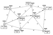
図1は、本発明の実施形態に係る経路生成方法の全体の流れの概略を示す図である。この方法は、後述する本発明の実施形態に係る自律移動装置としての自律移動ロボットにより実行される。各工程の詳細については後述する。
Hereinafter, embodiments of the present invention will be described in detail.
<Overall flow of route generation method>
FIG. 1 is a diagram showing an outline of the overall flow of a route generation method according to an embodiment of the present invention. This method is executed by an autonomous mobile robot as an autonomous mobile device according to an embodiment of the present invention described later. Details of each step will be described later.
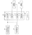
図示のように、この経路生成方法は、3次元点群データ計測工程1、地図生成工程2、経路生成工程3、および経路計画工程4を有する。そして、地図生成工程2は、ランドマーク選別工程21、ノイズ除去工程22、クラスタリング工程23、および2.5D地図写像工程24を有し、経路生成工程3は、経由地点設置工程31、安全度ラベリング工程32、および経路ネットワーク化工程33を有する。
As illustrated, this route generation method includes a three-dimensional point cloud
3次元点群データ計測工程1では、レーザーレンジファインダーやステレオカメラなど、ロボットから物体までの距離を3次元的に測距可能なセンサと、GPS(Global Positioning System)などロボット自身の自己位置を計測可能なセンサとを用いて、移動環境をスキャンして、3次元位置データとしての3次元点群データを取得する。
In the three-dimensional point cloud
ランドマーク選別工程21では、3次元点群データ計測工程1で取得された3次元の点群データから、ある閾値以上の高さを持ったデータのみを記録し、それ以外(ある閾値未満の高さを持ったデータ)を削除する。
In the
ノイズ除去工程22では、ランドマーク選別工程21で選別された3次元の点群データからのノイズを除去する。一般に、計測した点群データにはノイズ(外れ値)が多く含まれるので、公知のRANSAC(Random Sample Consensus)などのノイズ除去アルゴリズムでノイズを取り除く。
In the
クラスタリング工程23では、後の経由地点設置工程31における通行可能領域の処理の前処理として、障害物を一つの塊としてグループ化(クラスタ化)する。
In the clustering
2.5D地図写像工程24では、3次元点群データから2.5次元の地図への変換、すなわち高さ情報を保持したまま2次元地図へと写像を行う。この工程で環境地図の生成が終了する。
In the 2.5D
経由地点設置工程31では、生成された環境地図における各々の障害物の高さに応じて、できるだけ障害物から離れるような地点を計算し、自律移動の経由地点としてそのx,y座標を記憶する。
In the
安全度ラベリング工程32では、経由地点設置工程31で設置された経由地点において、障害物と障害物の間のスペースがあまりにも狭いときは、その経由地点を通行不可能地点として削除する。また、障害物間の距離(移動経路の幅)と障害物の高さを考慮して、その経由地点における自己位置推定の安全度(もしくは危険度)なるものを各地点に対して数値でラベリングする。
In the safety
経路ネットワーク化工程33では、安全度ラベリング工程32によるラベリングが終了した経由地点に対して、経由地点同士をドロネー三角領域分割によって直線で結び、通行可能な移動経路のネットワークを完成させる。
In the
経路計画工程4では、経路生成工程3で完成した経路ネットワークを用いて、経由地点の安全度を考慮しながら目的地までの自律移動経路を計算する。
In the
〈自律移動ロボットのハードウェア構成〉
図2は、本発明の実施形態に係る自律移動装置としての自律移動ロボット(以下、本実施形態に係る自律移動ロボット)のハードウェア構成の概略を示すブロック図である。
<Hardware configuration of autonomous mobile robot>
FIG. 2 is a block diagram showing an outline of a hardware configuration of an autonomous mobile robot (hereinafter referred to as an autonomous mobile robot according to the present embodiment) as an autonomous mobile device according to the embodiment of the present invention.
図示のように、本実施形態に係る自律移動ロボットは、演算装置100と、それぞれが演算装置100に接続された3次元計測センサ101、自己位置推定センサ102、HDDなどの記録媒体103、この自律移動ロボット(自装置)を駆動するモータなどの駆動部104、およびコントローラ105を有する。演算装置100とコントローラ105との間の接続は無線(ワイヤレス)でもよい。
As shown in the figure, the autonomous mobile robot according to the present embodiment includes an
3次元計測センサ101は、レーザーレンジファインダーやステレオカメラなど、ロボットから物体までの距離を3次元的に測距可能なセンサである。自己位置推定センサ102は、GPSやIMU(Inertial Measurement Unit:慣性計測装置)など、ロボット自身の自己位置を計測可能なセンサである。
The three-
演算装置100は、CPU、ROM、およびRAMを有するマイクロコンピュータなどで構成されており、CPUがROMに格納されているプログラムをRAMに読み込んで処理することにより実現される機能を表すブロックとして、地図生成部111、経路生成部112、経路計画部113、および駆動制御部114を備えている。
The
地図生成部111、経路生成部112、経路計画部113は、それぞれ図1における地図生成工程2、経路生成工程3、経路計画工程4を実行するブロックである。駆動制御部114は、駆動部104の動作を制御するブロックである。
The map generation unit 111, the
〈自律移動ロボットの動作の概略〉
次に、本実施形態に係る自律移動ロボットの動作の概略について説明する。
本実施形態に係る自律移動ロボットの動作状態には、地図生成フェーズと自律移動フェーズという2つの動作状態がある。
<Outline of autonomous mobile robot operation>
Next, an outline of the operation of the autonomous mobile robot according to the present embodiment will be described.
The operation state of the autonomous mobile robot according to the present embodiment includes two operation states, a map generation phase and an autonomous movement phase.
地図生成フェーズは、図1に示した3次元点群計測工程1、地図生成工程2、および経路生成工程3を実行するフェーズであり、自律移動フェーズは図1に示した経路計画工程4を実行しながらロボットを移動させるフェーズである。これらのフェーズは、ユーザがコントローラ105により手動で切り換えることができる。
The map generation phase is a phase for executing the three-dimensional point
地図生成フェーズでは、ユーザがコントローラ105から遠隔で指令を送ることで移動環境内においてロボットを動かして回り、3次元計測センサ101によりロボットから周囲の物体までの距離を計測するとともに、自己位置推定センサ102を用いて、移動環境を移動しながらスキャンして、環境地図のデータを生成する。生成された環境地図のデータは記録媒体103に一時的に蓄えられる。
In the map generation phase, the user moves the robot in the moving environment by sending a command remotely from the
また、地図生成フェーズでは、生成された環境地図における各々の障害物の高さに応じて、できるだけ障害物から離れるような地点を計算し、自律移動の経由地点の位置および安全度を記録媒体103に蓄積する。
Further, in the map generation phase, a point that is as far away from the obstacle as possible is calculated according to the height of each obstacle in the generated environmental map, and the position and safety level of the autonomous movement via point are recorded on the
自律移動フェーズでは、地図生成フェーズで生成された地図データおよび移動環境全体の移動経路を記録媒体103から読み出して、ロボットの現在位置から目的地の自律移動経路を計画する。
In the autonomous movement phase, the map data generated in the map generation phase and the movement route of the entire moving environment are read from the
その後、計画した自律移動経路に従い、現在位置から計画した自律移動経路の各経由地点を経由するように、駆動制御部114から駆動部104に動作の指令を送る。したがって、ロボットはユーザからのコントローラ指令なしに自律移動を行う。
Thereafter, according to the planned autonomous movement route, an operation command is sent from the
経路計画および自律移動中には、ロボットは現在位置を推定する必要があるので、自律移動フェーズにおいても自己位置推定センサ102を使用する。しかしながら、一度生成した環境地図および自律移動経路自体は更新しないので、3次元計測センサ101は自律移動フェーズでは使用せず、地図生成部111および経路生成部112は動作しない。
Since the robot needs to estimate the current position during route planning and autonomous movement, the self-
〈ランドマーク選定処理〉
図3は、本実施形態に係る自律移動ロボットにより実行されるランドマーク選定処理の詳細を示すフローチャートであり、図4は、本実施形態に係る自律移動ロボットにより実行されるランドマーク選定処理について説明するための模式図である。これらの図を用いて、ランドマーク選定処理について説明する。なお、このランドマーク選定処理は、図1における3次元点群データ計測工程1およびランドマーク選別工程21に対応する。
<Landmark selection process>
FIG. 3 is a flowchart showing details of the landmark selection process executed by the autonomous mobile robot according to the present embodiment, and FIG. 4 explains the landmark selection process executed by the autonomous mobile robot according to the present embodiment. It is a schematic diagram for doing. The landmark selection process will be described with reference to these drawings. This landmark selection process corresponds to the three-dimensional point cloud
まず、上記図2の説明でも述べたとおり、地図生成フェーズにおいて、ロボットはユーザがコントローラ105で遠隔操作しながら移動環境内を移動して回ると同時に、3次元スキャンを行う(図3のステップS1、図4A)。スキャンしたデータは3次元座標の点群として保持される(ステップS2、図4B)。
First, as described in the description of FIG. 2 above, in the map generation phase, the robot moves around in the moving environment while being remotely operated by the
それら点群の点ひとつひとつはx,y,zの3次元座標で与えられるが、z座標の値が高さに関するユーザ設定の閾値H_thresh未満であった場合、その点を保持せずに削除する(ステップS3:Yes→S4、図4C)。 Each point of the point group is given by three-dimensional coordinates of x, y, and z. If the value of the z coordinate is less than the user-set threshold value H_thresh regarding the height, the point is deleted without retaining ( Step S3: Yes → S4, FIG. 4C).
これは、高さの低い障害物は、そもそも自己位置推定を失敗させる原因にはならないため、高さの高い障害物の位置だけを残すことにする。この処理をある時刻でスキャンした点群データ全ての点に対して行う(ステップS5:No→S3)。 This is because an obstacle with a low height does not cause the self-position estimation to fail in the first place, so only the position of the obstacle with a high height is left. This process is performed for all points scanned at a certain time (step S5: No → S3).
次に、データ量削減およびマッチングの高速化のため、残った点群を3次元の格子座標で量子化する(ステップS6、図4D)。その後、全ての領域をスキャンしたか否かを判定し(ステップS7)、スキャンしていない場合は(ステップS7:No)、ICP(Interactive Closest Points)マッチングのような公知の既存手法により、それまでに取得した点群とのマッチングを行って、段階的に地図を拡張する(ステップS8、図4E)。 Next, in order to reduce the amount of data and speed up matching, the remaining point group is quantized with three-dimensional lattice coordinates (step S6, FIG. 4D). Thereafter, it is determined whether or not all the regions have been scanned (step S7). If not scanned (step S7: No), the conventional method such as ICP (Interactive Closest Points) matching is used so far. The map is expanded step by step by matching with the acquired point cloud (step S8, FIG. 4E).
そして、ロボットを少し前進させ(ステップS9)、ロボットの自己位置をマッピングした後(図3のステップS10)、再びスキャンする(ステップS1)。この処理を繰り返し、全ての領域をスキャンしたら(ステップS7:Yes)、この図に示すフローを終了し、移動環境全体の環境地図を完成させる。 Then, the robot is moved forward a little (step S9), the robot's own position is mapped (step S10 in FIG. 3), and then scanned again (step S1). When this process is repeated and all areas are scanned (step S7: Yes), the flow shown in this figure is terminated, and the environment map of the entire mobile environment is completed.
最終的に完成した環境地図は、後述する図5Aに示すような格子状の地図となる。各グリッドで仕切られた範囲に存在する点群はまとめてひとつの格子として表される。ひとつの格子はそのx,y座標と障害物の存在の有無、および障害物(点群)の最大高さh_maxを示したデータとなる。 The finally completed environmental map is a grid-like map as shown in FIG. 5A described later. A group of points existing in a range partitioned by each grid are collectively represented as one grid. One grid is data indicating the x and y coordinates, the presence / absence of an obstacle, and the maximum height h_max of the obstacle (point group).
〈2.5D地図の生成〉
図5は、3次元格子地図と2.5D地図との関係を示す模式図である。ここで、図5Aは3次元格子地図を表し、図5Bは2.5D地図を表す。この図を用いて、ランドマーク選定後から2.5D地図生成までの処理の流れ、すなわち図1におけるノイズ除去工程22、クラスタリング工程23、および2.5D地図写像工程24の内容について説明する。
<2.5D map generation>
FIG. 5 is a schematic diagram showing the relationship between a three-dimensional lattice map and a 2.5D map. Here, FIG. 5A represents a three-dimensional lattice map, and FIG. 5B represents a 2.5D map. The flow of processing from landmark selection to 2.5D map generation, that is, the contents of the
ランドマーク選定後のデータは、図5Aのようにある一定以上の高さをもった3次元格子状の地図で表され、木などの障害物が存在する空間は立方体で表される。 The data after selecting the landmark is represented by a three-dimensional lattice-shaped map having a certain height or more as shown in FIG. 5A, and the space where obstacles such as trees are present is represented by a cube.
取得した3次元点群データはノイズを多く含んでいることが多いので、次のステップでは、公知のRANSACに代表されるような外れ値手法でノイズを除去する(ノイズ除去工程22)。 Since the acquired three-dimensional point cloud data often contains a lot of noise, in the next step, noise is removed by an outlier method typified by a known RANSAC (noise removal step 22).
さらに、k-meansクラスタリングなどに代表されるようなクラスタリング手法によって、これら障害物の3次元点群をクラスタ化し、それらひとつひとつのクラスタを障害物クラスタとして定義する(クラスタリング工程23)。 Further, a three-dimensional point cloud of these obstacles is clustered by a clustering technique represented by k-means clustering and the like, and each of these clusters is defined as an obstacle cluster (clustering step 23).
なお、既存手法によっては、ノイズ除去をクラスタリングと同時に、もしくはランドマーク選別の点群マッチング処理で同時に行うことも可能な場合があり、その際は個別のノイズ除去は不要である。 Depending on the existing method, noise removal may be performed simultaneously with clustering or with point group matching processing for landmark selection, in which case individual noise removal is not necessary.
最後に、上記3次元点群について、高さ情報を保存したまま2次元の地図として平面射影する(2.5D地図写像工程24)。その様子を図5に示す。図5Bに示す2.5次元格子地図において黒い部分が障害物の存在する領域を示している。このひとつの格子は、そこに障害物が存在すればそのx,y座標に加え、最大高さ情報(h_max)、およびその格子が属するクラスタID情報(c_id)も含んでいる。最大高さ情報とクラスタID情報は、後の経路生成工程3で使用される。
Finally, the three-dimensional point cloud is planarly projected as a two-dimensional map while maintaining the height information (2.5D map mapping step 24). This is shown in FIG. In the 2.5-dimensional lattice map shown in FIG. 5B, the black portion indicates an area where an obstacle exists. This single grid includes maximum height information (h_max) and cluster ID information (c_id) to which the grid belongs in addition to the x and y coordinates if an obstacle exists there. The maximum height information and the cluster ID information are used in a later
〈移動経路の生成〉
図6は、本実施形態に係る自律移動ロボットの経路生成部により実行される経由地点設置処理の詳細を示すフローチャートであり、図7は、本実施形態に係る自律移動ロボットの経路生成部により実行される経由地点設置処理および安全度ラベリング処理について説明するための模式図である。
<Generation of travel route>
FIG. 6 is a flowchart showing details of the waypoint setting process executed by the route generation unit of the autonomous mobile robot according to the present embodiment, and FIG. 7 is executed by the route generation unit of the autonomous mobile robot according to the embodiment. It is a schematic diagram for demonstrating the waypoint installation process and safety level labeling process.
《経由地点設置処理》
木などの高い障害物は、その高さが高いほどGPS電波の遮蔽の影響を受ける範囲が広くなる。そこで、障害物の高さが高くなるほど遠い地点を経由するように、経由地点を設置する。その処理の全体フローを示したのが図6である。以下、具体的な処理内容について説明する。
<Via-point installation processing>
The higher the height of obstacles such as trees, the wider the range affected by GPS radio wave shielding. Therefore, a waypoint is set up so that it goes through a far point as the height of the obstacle increases. FIG. 6 shows the overall flow of the processing. Specific processing contents will be described below.
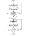
最初に障害物クラスタの最大高さ(高さの最大値)をそれぞれの障害物クラスタに対して計算する(ステップS11)。次に、障害物クラスタの重心位置を計算する(ステップS12)。ここでは、そのクラスタに含まれる格子ブロックのx座標およびy座標の平均値を計算して重心位置を求める。 First, the maximum height (maximum height) of the obstacle cluster is calculated for each obstacle cluster (step S11). Next, the center of gravity position of the obstacle cluster is calculated (step S12). Here, the average position of the x-coordinate and y-coordinate of the lattice block included in the cluster is calculated to obtain the centroid position.
全ての障害物クラスタについてチェック(最大高さおよび重心位置の計算)するまで(ステップS13:No)、ステップS11およびS12を繰り返し、全ての障害物クラスタをチェックしたら(ステップS13:Yes)、次に、その障害物クラスタの近傍にあるクラスタを計算するため、各クラスタの重心位置をノードとして公知のドロネー三角形領域分割によって各ノードを線で結ぶ(ステップS14)。 Until all obstacle clusters are checked (calculation of maximum height and center of gravity) (step S13: No), steps S11 and S12 are repeated to check all obstacle clusters (step S13: Yes). In order to calculate a cluster in the vicinity of the obstacle cluster, each node is connected by a line by known Delaunay triangular region division using the center of gravity of each cluster as a node (step S14).
さらに、各ノードを結ぶ線分上に経由地点を設定するため、線分で結ばれたクラスタの最大高さの比率を計算し(ステップS15)、その比率をとった位置に経由地点のx,y座標を設定する(ステップS16)。 Further, in order to set a waypoint on the line segment connecting each node, the ratio of the maximum heights of the clusters connected by the line segment is calculated (step S15), and the route point x, The y coordinate is set (step S16).
図7の場合、障害物クラスタOiの高さがh1、障害物クラスタOjの高さがh2、それらの重心位置を結ぶ線分の長さがdである。そして、障害物クラスタOiの重心から{d×h1/(h1+h2)}であり、かつ障害物クラスタOjの重心から{d×h2/(h1+h2)}である位置に経由地点が設定されている。 In the case of FIG. 7, the height of the obstacle cluster Oi is h1, the height of the obstacle cluster Oj is h2, and the length of the line segment connecting the positions of the centers of gravity is d. A waypoint is set at a position {d × h1 / (h1 + h2)} from the center of gravity of the obstacle cluster Oi and {d × h2 / (h1 + h2)} from the center of gravity of the obstacle cluster Oj.
全ての障害物クラスタのペアについて同様の処理を実行し(ステップS17:No→S15→S16)、それが終了したら(ステップS17:Yes)、この図に示す経由地点設置処理が終了する。 The same processing is executed for all the obstacle cluster pairs (step S17: No → S15 → S16), and when the processing ends (step S17: Yes), the waypoint installation processing shown in FIG.
《安全度ラベリング処理》
次に図7を用いて安全度ラベリング処理について説明する。
上記までの処理で述べた手法は、障害物の高さを考慮して、できるだけそのような障害物から遠い地点を経由する方法であった。しかし、同じ地点であっても常に安定してGPSの電波を受信可能であるとは限らない。また、空撮による自己位置推定の場合は、日の当たり方によっては障害物の影が発生し、そのような場所ではロボットの位置が捕らえにくい。したがって、多少遠回りしてでも自己位置を見失うことなく安全に移動したい場合がある。また、障害物と障害物の隙間があまりにも狭い場合、どこを通ってもGPSの電波遮断の影響を受ける。加えて、そもそもロボットが通れる分だけのスペースがない場合もある。
《Safety level labeling processing》
Next, the safety level labeling process will be described with reference to FIG.
The method described in the above processing is a method of passing through a point as far as possible from such an obstacle in consideration of the height of the obstacle. However, it is not always possible to stably receive GPS radio waves even at the same point. In addition, in the case of self-position estimation by aerial photography, obstacle shadows occur depending on how the sun hits, and it is difficult to capture the position of the robot in such a place. Therefore, there is a case where it is desired to move safely without losing sight of the self-position even if it makes a slight detour. In addition, when the gap between the obstacles is too narrow, it is affected by GPS radio wave blocking everywhere. In addition, there may not be enough space for the robot to pass through.
そこで、具体的な処理として、まず2つの障害物クラスタ間の距離を計算する。距離は、図7に示すように、そのクラスタの最短距離wで定義する。次に、その障害物クラスタ間の最短距離がある閾値以下ならば、その障害物クラスタの間に設置された経由地点を削除する。 Therefore, as a specific process, first, a distance between two obstacle clusters is calculated. The distance is defined by the shortest distance w of the cluster as shown in FIG. Next, if the shortest distance between the obstacle clusters is equal to or smaller than a threshold value, the waypoints installed between the obstacle clusters are deleted.
次のステップとして、残った経由地点については、2つの障害物クラスタ間の最短距離、およびそれぞれのクラスタにおける最大高さを考慮して、その経由地点がどれだけ電波遮蔽などといった高い障害物の影響を受けやすいか(安全度、もしくは危険度)を数値でラベリングする。 As the next step, for the remaining waypoints, considering the shortest distance between the two obstacle clusters and the maximum height in each cluster, how much the waypoints are affected by high obstructions such as radio wave shielding Label with a numerical value whether it is easy to receive (safety or risk).
危険度に関しては、例えば以下の式〔1〕によって計算する。
Danger(Oi,Oj)=1/(h1*h2*1/w(Oi,Oj)) …式〔1〕
ここで、Danger(Oi,Oj)は障害物OiとOj間の経由地点の危険度、w(Oi,Oj)は障害物OiとOj間の距離を表す。
For example, the risk is calculated by the following equation [1].
Danger (Oi, Oj) = 1 / (h1 * h2 * 1 / w (Oi, Oj)) Equation [1]
Here, Danger (Oi, Oj) represents the danger level of the waypoint between the obstacles Oi and Oj, and w (Oi, Oj) represents the distance between the obstacles Oi and Oj.
また、人手によってロボットの通行を許可する閾値を設定し、障害物と障害物の間の距離(移動経路の幅)がその閾値以下であった場合は、危険度∞(もしくは安全度0)としてロボットがその地点を経由しないように設定することを行う。この閾値は、ロボット本体の大きさや高さに応じてユーザが決定することができる。 In addition, if a threshold is set for allowing the robot to pass by hand, and the distance between obstacles (the width of the movement path) is less than or equal to the threshold, the risk level is ∞ (or safety level is 0). The robot is set not to go through that point. This threshold value can be determined by the user according to the size and height of the robot body.
最後に、これらの処理を前記の経由地点設置処理で結ばれた全てのクラスタのペア同士に関して行う。 Finally, these processes are performed for all pairs of clusters connected by the waypoint installation process.
ここで生成される移動経路は、経由地点を直線で結んだネットワークで表現されている。こうすることで、ロボットが記憶すべきデータ量を削減できるとともに、ロボットが自律移動の計画を行う際にかかる計算時間を短縮することができる。 The travel route generated here is represented by a network connecting the waypoints with straight lines. By doing so, the amount of data to be stored by the robot can be reduced, and the calculation time required for the robot to plan for autonomous movement can be shortened.
〈経路計画工程〉
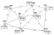
図8は、本実施形態に係る自律移動ロボットの経路生成部で生成されたネットワーク構造の経路データを示す図であり、図9は、経由地点の安全度を考慮した経路計画について説明するための図である。これらの図を用いて、経路計画の手法について説明する。
<Route planning process>
FIG. 8 is a diagram showing route data of the network structure generated by the route generation unit of the autonomous mobile robot according to the present embodiment. FIG. 9 is a diagram for explaining route planning in consideration of the safety degree of the waypoints. FIG. The route planning method will be described with reference to these drawings.
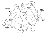
経路生成部112によって得られた経路データは図8のようなネットワーク構造になる。この図において、楕円や円は障害物クラスタ、星形は経由地点、経由地点を結ぶ点線は通行可能な移動経路を表す。このようなネットワーク構造に対する経路計画の既存手法として、代表的なものにA*探索やダイクストラ法などが挙げられる。
The route data obtained by the
A*探索やダイクストラ法のような既存の経路計画手法では、目的地までの最短経路を探索する。したがって、ネットワークにおけるエッジの長さのみが評価の対象である。これに対して、本実施形態に係る経路計画工程では、背の高い障害物に起因する外乱を軽減するため、目的地まで遠回りすることを許可する点が異なる。 In existing route planning methods such as A * search and Dijkstra method, the shortest route to the destination is searched. Therefore, only the length of the edge in the network is the object of evaluation. On the other hand, the route planning process according to the present embodiment is different in that it is permitted to make a detour to the destination in order to reduce disturbance caused by a tall obstacle.
すなわち、本実施形態に係る経路計画工程では、上記従来手法において、図8に示すような経由地点の安全度で重み付けたものをエッジの長さ(経路の長さ)に加えて拡張する。具体的には、例として以下の式〔2〕で移動コストを計算する。
Cost(Vi,Vj)=Dist(Vi,Vj)+α*Danger(Vj) …式〔2〕
That is, in the route planning process according to the present embodiment, in the above-described conventional method, the weighting based on the safety degree of the waypoint as shown in FIG. 8 is extended in addition to the edge length (route length). Specifically, as an example, the movement cost is calculated by the following equation [2].
Cost (Vi, Vj) = Dist (Vi, Vj) + α * Danger (Vj) Equation [2]
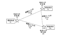
ここで、Cost(Vi,Vj)は経由地点ViからVjに至る移動コストを表し、Dist(Vi,Vj)はViとVj間の距離、Danger(Vj)はVjにおける危険度(または安全度)、αはユーザがどれだけ安全度を考慮するかのスケーリングパラメータである。 Here, Cost (Vi, Vj) represents the travel cost from the waypoint Vi to Vj, Dist (Vi, Vj) is the distance between Vi and Vj, and Danger (Vj) is the risk (or safety) at Vj. , Α is a scaling parameter for how much safety is considered by the user.
図9の計算例では、経由地点ViからVjへ至る移動コストであるCost(Vi,Vj)は、Dist(Vi,Vj)=10、Danger(Vj)=30であるから、α=1.0とした場合、Cost(Vi,Vj)=40となる。 In the calculation example of FIG. 9, Cost (Vi, Vj), which is the movement cost from the via point Vi to Vj, is Dist (Vi, Vj) = 10 and Danger (Vj) = 30, so α = 1.0. In this case, Cost (Vi, Vj) = 40.
なお、目的地の座標はユーザ自身で与えるが、目的地を含めた自律移動経路は自動で生成する。ユーザから与えられた目的地から各経由地点までの距離を計算し、目的地とそれに最も近い経由地点を線で結ぶことで、目的地までの経路を生成する。同様にして、自律移動のスタート地点に関しても、それに最も近い経由地点とスタート地点を線で結ぶことで経路を生成する。 Although the coordinates of the destination are given by the user himself, an autonomous movement route including the destination is automatically generated. The distance from the destination given by the user to each waypoint is calculated, and the route to the destination is generated by connecting the destination and the nearest waypoint with a line. Similarly, a route is also generated for the starting point of autonomous movement by connecting the nearest waypoint and the starting point with a line.
〈既存の経路計画の手法と本実施形態に係る経路計画の手法〉
図10は、経路データにおける移動距離のみを考慮した経路計画について説明するための図であり、図11は、経由地点の危険度を考慮した経路計画について説明するための図である。これらの図において、星形は地点(スタート地点、経由地点、ゴール地点)であり、地点を結ぶ点線は通行可能な移動経路であり、実線の矢印は探索された自律移動経路である。また、通行可能な移動経路および探索された自律移動経路に付された数値は地点間の距離である。
<Existing route planning method and route planning method according to this embodiment>
FIG. 10 is a diagram for explaining a route plan that takes into account only the moving distance in the route data, and FIG. 11 is a diagram for explaining a route plan that takes into account the risk of a waypoint. In these figures, the star shape is a point (start point, waypoint, goal point), the dotted line connecting the points is a traversable movement route, and the solid line arrow is the searched autonomous movement route. Moreover, the numerical value attached | subjected to the movement path | route which can be passed, and the searched autonomous movement path | route is the distance between points.
前述したように、A*探索やダイクストラ法のような既存の経路計画手法では、目的地までの最短経路を探索するため、図10の例のように、スタート地点Sからゴール地点Gまでの最短経路(S→V2→V5→G、経路長の合計:5+5+5=15)が生成される。しかし、このときの危険度は合計で「10+90+100+10=210」にもなり、特に危険度の高い地点V2とV5を経由することになる。 As described above, in the existing route planning method such as A * search or Dijkstra method, the shortest route from the start point S to the goal point G is searched as shown in the example of FIG. A route (S-> V2-> V5-> G, total route length: 5 + 5 + 5 = 15) is generated. However, the risk level at this time is “10 + 90 + 100 + 10 = 210” in total, and the route passes through points V2 and V5 having particularly high risk levels.
一方、本実施形態のように安全度を重視する経路計画方法では、図11のようにゴールまで多少遠回りする自律移動経路を計画することも許可するので(S→V3→V6→G、経路長の合計:15+80+80=175)、移動距離や移動時間は既存手法よりも増加する。 On the other hand, in the route planning method emphasizing safety as in the present embodiment, it is also permitted to plan an autonomous movement route that slightly detours to the goal as shown in FIG. 11 (S → V3 → V6 → G, route length). Total: 15 + 80 + 80 = 175), and the movement distance and movement time increase compared to the existing method.
しかしながら、危険度は合計で「10+10+5+10=35」であり、図10の例よりも安全な経路を通ることがわかる。そのため、本手法のほうが自己位置推定に失敗する可能性の低い自律移動経路を計画できていることがわかる。 However, the degree of risk is “10 + 10 + 5 + 10 = 35” in total, and it can be seen that the route is safer than the example of FIG. Therefore, it can be seen that this method can plan an autonomous movement route that is less likely to fail in self-position estimation.
また、本実施形態においても、α=0として安全度を無視すれば、移動経路のコストだけを考慮した既存手法と等価な経路計画を行うこともできる。 Also in this embodiment, if the safety degree is ignored with α = 0, it is possible to perform a route plan equivalent to the existing method considering only the cost of the moving route.
以上詳細に説明したように、本実施形態に係る自律移動ロボットは、下記(1)〜(3)の特徴を備えている。
(1)ランドマーク(標識)として所定の高さ以上の障害物のみを選別してその存在位置を環境地図のデータとして記録するので、障害物が存在する屋外環境において、記録する環境地図のデータ量を少なくすることができる。
(2)環境地図における障害物の高さに応じて自律移動の経由地点を設定してネットワーク構造で移動経路を表現するので、移動経路のデータ量を削減することができる。その結果、自己位置を推定する際の経路計画の処理時間を短縮することができる。
(3)各経由地点における自己位置を見失う危険性を考慮した経路計画を行うので、高さの高い障害物が存在する屋外環境において、ロボット自身が自己位置を見失うことなく自律移動することができる。
As described above in detail, the autonomous mobile robot according to the present embodiment has the following features (1) to (3).
(1) Since only obstacles of a predetermined height or higher are selected as landmarks (signs) and their locations are recorded as environmental map data, environmental map data to be recorded in an outdoor environment where obstacles exist The amount can be reduced.
(2) Since the route of autonomous movement is set according to the height of the obstacle in the environmental map and the movement route is expressed by the network structure, the data amount of the movement route can be reduced. As a result, it is possible to shorten the processing time for route planning when estimating the self-position.
(3) Since route planning is performed in consideration of the risk of losing sight of the self-position at each waypoint, the robot itself can move autonomously without losing sight of the self-position in an outdoor environment where obstacles with high height exist. .
なお、本発明は、以上説明した実施形態に限定されるものではなく、例えば図1の地図生成工程2、経路生成工程3、および経路計画工程4をロボットと通信するサーバが実行するようにした自律移動システムを構成することもできる。また、ロボットが自律移動経路上の経由地点を通過したことを検出する手段を設けることもできる。
Note that the present invention is not limited to the embodiment described above. For example, the server that communicates with the robot executes the
1…3次元点群データ計測工程、2…地図生成工程、3…経路生成工程、4…経路計画工程、21…ランドマーク選別工程、22…ノイズ除去工程、23…クラスタリング工程、24…2.5D地図写像工程、31…経由地点設置工程、32…安全度ラベリング工程、33…経路ネットワーク化工程、100…演算装置、101…3次元計測センサ、102…自己位置推定センサ、103…記録媒体、104…駆動部、105…コントローラ、111…地図生成部、112…経路生成部、113…経路計画部、114…駆動制御部。
DESCRIPTION OF
Claims (9)
前記3次元計測センサで生成された3次元位置データから、所定の閾値以上の高さを有する障害物の位置を示す環境地図を生成する地図生成手段と、
前記地図生成手段により生成された環境地図から通行可能な移動経路を生成する経路生成手段と、
前記経路生成手段により生成された移動経路から目的地までの自律移動経路を生成する経路計画手段と、
前記経路計画手段により生成された自律移動経路を自装置が移動するように制御する移動制御手段と、
を有する自律移動装置。 A three-dimensional measurement sensor that measures a moving environment and generates three-dimensional position data;
Map generation means for generating an environmental map indicating the position of an obstacle having a height equal to or higher than a predetermined threshold from the three-dimensional position data generated by the three-dimensional measurement sensor;
Route generation means for generating a travel route that can be passed from the environmental map generated by the map generation means;
Route planning means for generating an autonomous movement route from the movement route generated by the route generation means to the destination;
Movement control means for controlling the own apparatus to move the autonomous movement route generated by the route planning means;
An autonomous mobile device.
前記地図生成手段は、前記3次元計測センサで生成された3次元位置データのうち、所定の閾値未満の高さを持つ3次元位置データを削除する手段と、前記3次元位置データを、その高さデータを保持したまま2次元地図へ写像する手段と、を有する、自律移動装置。 In the autonomous mobile device according to claim 1,
The map generating means deletes three-dimensional position data having a height less than a predetermined threshold from the three-dimensional position data generated by the three-dimensional measurement sensor; Means for mapping to a two-dimensional map while retaining the data.
前記経路生成手段は、前記障害物の高さに応じて経由地点を設定する経由地点設定手段を有する、自律移動装置。 In the autonomous mobile device according to claim 1 or 2,
The route generation means is an autonomous mobile device having route point setting means for setting a route point according to the height of the obstacle.
前記経路生成手段は、前記障害物の高さ、および複数の前記障害物の間の距離から、前記経由地点の安全度をラベリングする手段を有する、自律移動装置。 In the autonomous mobile device according to claim 3,
The autonomous mobile device, wherein the route generation means includes means for labeling a safety degree of the waypoint from a height of the obstacle and a distance between the plurality of obstacles.
前記経路生成手段は、経由地点を線で結ぶネットワーク化手段を有する、自律移動装置。 In the autonomous mobile device according to any one of claims 1 to 4,
The route generation means is an autonomous mobile device having networking means for connecting via points with lines.
前記経路計画手段は、前記経由地点の安全度を考慮して、スタート地点からゴール地点までの自律移動経路を生成する、自律移動装置。 In the autonomous mobile device according to claim 4 or 5,
The route planning means is an autonomous mobile device that generates an autonomous movement route from a start point to a goal point in consideration of the safety degree of the waypoint.
前記3次元計測センサで生成された3次元位置データから、所定の閾値以上の高さを有する障害物の位置を示す環境地図を生成する地図生成手段と、
前記地図生成手段により生成された環境地図から通行可能な移動経路を生成する経路生成手段と、
前記経路生成手段により生成された移動経路から目的地までの自律移動経路を生成する経路計画手段と、
前記経路計画手段により生成された自律移動経路を前記自律移動装置が移動するように制御する移動制御手段と、
を有する自律移動システム。 A three-dimensional measurement sensor for measuring the moving environment of the autonomous mobile device and generating three-dimensional position data;
Map generation means for generating an environmental map indicating the position of an obstacle having a height equal to or higher than a predetermined threshold from the three-dimensional position data generated by the three-dimensional measurement sensor;
Route generation means for generating a travel route that can be passed from the environmental map generated by the map generation means;
Route planning means for generating an autonomous movement route from the movement route generated by the route generation means to the destination;
Movement control means for controlling the autonomous mobile device to move the autonomous movement route generated by the route planning means;
An autonomous mobile system.
前記地図生成工程により生成された環境地図から通行可能な移動経路を生成する経路生成工程と、
前記経路生成工程により生成された移動経路から目的地までの自律移動経路を生成する経路計画工程と、
前記経路計画工程により生成された自律移動経路を前記自律移動装置が移動する自律移動工程と、
を有する自律移動方法。 A map generation step of measuring an environment of the autonomous mobile device and generating an environment map indicating the position of an obstacle above a predetermined height;
A route generation step of generating a travel route that is accessible from the environmental map generated by the map generation step;
A route planning step for generating an autonomous movement route from the movement route generated by the route generation step to the destination;
An autonomous movement step in which the autonomous mobile device moves on the autonomous movement route generated by the route planning step;
An autonomous mobile method.
A program for causing a computer to function as each means of the autonomous mobile device according to claim 1.
Priority Applications (1)
| Application Number | Priority Date | Filing Date | Title |
|---|---|---|---|
| JP2015026744A JP2016149090A (en) | 2015-02-13 | 2015-02-13 | Autonomous mobile device, autonomous mobile system, autonomous mobile method and program |
Applications Claiming Priority (1)
| Application Number | Priority Date | Filing Date | Title |
|---|---|---|---|
| JP2015026744A JP2016149090A (en) | 2015-02-13 | 2015-02-13 | Autonomous mobile device, autonomous mobile system, autonomous mobile method and program |
Publications (1)
| Publication Number | Publication Date |
|---|---|
| JP2016149090A true JP2016149090A (en) | 2016-08-18 |
Family
ID=56691268
Family Applications (1)
| Application Number | Title | Priority Date | Filing Date |
|---|---|---|---|
| JP2015026744A Pending JP2016149090A (en) | 2015-02-13 | 2015-02-13 | Autonomous mobile device, autonomous mobile system, autonomous mobile method and program |
Country Status (1)
| Country | Link |
|---|---|
| JP (1) | JP2016149090A (en) |
Cited By (8)
| Publication number | Priority date | Publication date | Assignee | Title |
|---|---|---|---|---|
| JP2018169698A (en) * | 2017-03-29 | 2018-11-01 | 西日本電信電話株式会社 | Position estimation device, position estimation method, and position estimation program |
| CN109240303A (en) * | 2018-09-30 | 2019-01-18 | 北京奇虎科技有限公司 | A kind of paths planning method of robot, device and electronic equipment |
| JPWO2018221453A1 (en) * | 2017-05-31 | 2020-03-26 | パイオニア株式会社 | Output device, control method, program, and storage medium |
| CN112257889A (en) * | 2019-07-21 | 2021-01-22 | 长沙智能驾驶研究院有限公司 | Route planning method and device for ground moving object in intelligent construction site |
| CN112669466A (en) * | 2020-12-23 | 2021-04-16 | 北京像素软件科技股份有限公司 | Virtual space path planning method and device, electronic equipment and storage medium |
| WO2021235100A1 (en) * | 2020-05-20 | 2021-11-25 | ソニーグループ株式会社 | Information processing device, information processing method, and program |
| US11493359B2 (en) | 2018-01-24 | 2022-11-08 | Sony Corporation | Control device, control method, and mobile object |
| JP2022553248A (en) * | 2019-10-16 | 2022-12-22 | ホアウェイ・テクノロジーズ・カンパニー・リミテッド | Methods and systems for real-time localization of autonomous vehicles |
-
2015
- 2015-02-13 JP JP2015026744A patent/JP2016149090A/en active Pending
Cited By (9)
| Publication number | Priority date | Publication date | Assignee | Title |
|---|---|---|---|---|
| JP2018169698A (en) * | 2017-03-29 | 2018-11-01 | 西日本電信電話株式会社 | Position estimation device, position estimation method, and position estimation program |
| JPWO2018221453A1 (en) * | 2017-05-31 | 2020-03-26 | パイオニア株式会社 | Output device, control method, program, and storage medium |
| US11493359B2 (en) | 2018-01-24 | 2022-11-08 | Sony Corporation | Control device, control method, and mobile object |
| CN109240303A (en) * | 2018-09-30 | 2019-01-18 | 北京奇虎科技有限公司 | A kind of paths planning method of robot, device and electronic equipment |
| CN112257889A (en) * | 2019-07-21 | 2021-01-22 | 长沙智能驾驶研究院有限公司 | Route planning method and device for ground moving object in intelligent construction site |
| JP2022553248A (en) * | 2019-10-16 | 2022-12-22 | ホアウェイ・テクノロジーズ・カンパニー・リミテッド | Methods and systems for real-time localization of autonomous vehicles |
| JP7358636B2 (en) | 2019-10-16 | 2023-10-10 | ホアウェイ・テクノロジーズ・カンパニー・リミテッド | Method and system for real-time localization of autonomous vehicles |
| WO2021235100A1 (en) * | 2020-05-20 | 2021-11-25 | ソニーグループ株式会社 | Information processing device, information processing method, and program |
| CN112669466A (en) * | 2020-12-23 | 2021-04-16 | 北京像素软件科技股份有限公司 | Virtual space path planning method and device, electronic equipment and storage medium |
Similar Documents
| Publication | Publication Date | Title |
|---|---|---|
| JP2016149090A (en) | Autonomous mobile device, autonomous mobile system, autonomous mobile method and program | |
| KR102273559B1 (en) | Method, apparatus, and computer readable storage medium for updating electronic map | |
| CN109916393B (en) | Multi-grid-value navigation method based on robot pose and application thereof | |
| US11320823B2 (en) | Method of navigating a vehicle and system thereof | |
| JP6849330B2 (en) | Map generation method, self-position estimation method, robot system, and robot | |
| US10352711B2 (en) | Computer-implemented method and a system for guiding a vehicle within a scenario with obstacles | |
| JP6608456B2 (en) | Estimation apparatus, control method, program, and storage medium | |
| CN110119140A (en) | System and method for acceleration curve projection | |
| KR20120046974A (en) | Moving robot and simultaneous localization and map-buliding method thereof | |
| KR20180093934A (en) | Autonomous visual navigation | |
| JP2019512668A (en) | Root deviation recognition method, terminal, and storage medium | |
| CN107436148A (en) | A kind of robot navigation method and device based on more maps | |
| CN106406320A (en) | Robot path planning method and robot planning route | |
| CN105335597B (en) | For obtaining the method and system of the trajectory model of route | |
| JP2022542807A (en) | intermediate waypoint generator | |
| WO2012086029A1 (en) | Autonomous movement system | |
| JP2017072422A (en) | Information processing device, control method, program, and storage medium | |
| KR20190082061A (en) | Method and apparatus for identifying intersections in an electronic map | |
| KR101598385B1 (en) | Autonomous driving method and robot using recognition scene based on straight line information | |
| JP2016024598A (en) | Control method of autonomous mobile apparatus | |
| JP2013025401A (en) | Self-position estimation device, self-position estimation method and program | |
| KR101299134B1 (en) | Searching system and method for moving targets in dynamic environment by cooperation of plural robots | |
| KR20200043005A (en) | Method and device to train image recognition model and to recognize image | |
| Teixeira et al. | Autonomous aerial inspection using visual-inertial robust localization and mapping | |
| KR20160048530A (en) | Method and apparatus for generating pathe of autonomous vehicle |