JP2016147652A - Vehicle display control device and vehicle display unit - Google Patents
Vehicle display control device and vehicle display unit Download PDFInfo
- Publication number
- JP2016147652A JP2016147652A JP2015236915A JP2015236915A JP2016147652A JP 2016147652 A JP2016147652 A JP 2016147652A JP 2015236915 A JP2015236915 A JP 2015236915A JP 2015236915 A JP2015236915 A JP 2015236915A JP 2016147652 A JP2016147652 A JP 2016147652A
- Authority
- JP
- Japan
- Prior art keywords
- virtual image
- image display
- emphasized
- vehicle
- display control
- Prior art date
- Legal status (The legal status is an assumption and is not a legal conclusion. Google has not performed a legal analysis and makes no representation as to the accuracy of the status listed.)
- Granted
Links
- 230000015654 memory Effects 0.000 abstract description 23
- 230000004048 modification Effects 0.000 description 58
- 238000012986 modification Methods 0.000 description 58
- 238000000034 method Methods 0.000 description 26
- 230000008569 process Effects 0.000 description 21
- 230000009471 action Effects 0.000 description 14
- 238000001514 detection method Methods 0.000 description 14
- 238000012544 monitoring process Methods 0.000 description 14
- 230000001276 controlling effect Effects 0.000 description 11
- 230000006870 function Effects 0.000 description 10
- 230000000694 effects Effects 0.000 description 8
- 238000012545 processing Methods 0.000 description 8
- 238000000926 separation method Methods 0.000 description 8
- 108091033322 FsrA Proteins 0.000 description 6
- 239000000446 fuel Substances 0.000 description 6
- 230000003044 adaptive effect Effects 0.000 description 4
- 230000008859 change Effects 0.000 description 4
- 239000003086 colorant Substances 0.000 description 3
- 238000002485 combustion reaction Methods 0.000 description 3
- 238000004891 communication Methods 0.000 description 3
- 238000010586 diagram Methods 0.000 description 3
- 230000012447 hatching Effects 0.000 description 3
- 239000004973 liquid crystal related substance Substances 0.000 description 3
- 238000012423 maintenance Methods 0.000 description 3
- 230000002093 peripheral effect Effects 0.000 description 3
- XLYOFNOQVPJJNP-UHFFFAOYSA-N water Substances O XLYOFNOQVPJJNP-UHFFFAOYSA-N 0.000 description 3
- 230000004907 flux Effects 0.000 description 2
- 230000003287 optical effect Effects 0.000 description 2
- 230000004044 response Effects 0.000 description 2
- 241001465754 Metazoa Species 0.000 description 1
- 238000005452 bending Methods 0.000 description 1
- 150000001875 compounds Chemical class 0.000 description 1
- 239000002826 coolant Substances 0.000 description 1
- 239000000498 cooling water Substances 0.000 description 1
- 230000003247 decreasing effect Effects 0.000 description 1
- 238000005516 engineering process Methods 0.000 description 1
- 230000002708 enhancing effect Effects 0.000 description 1
- 239000002828 fuel tank Substances 0.000 description 1
- 239000011521 glass Substances 0.000 description 1
- 238000002347 injection Methods 0.000 description 1
- 239000007924 injection Substances 0.000 description 1
- 230000001105 regulatory effect Effects 0.000 description 1
- 239000004065 semiconductor Substances 0.000 description 1
- 238000009751 slip forming Methods 0.000 description 1
- 230000000007 visual effect Effects 0.000 description 1
Images


Classifications
-
- G—PHYSICS
- G02—OPTICS
- G02B—OPTICAL ELEMENTS, SYSTEMS OR APPARATUS
- G02B27/00—Optical systems or apparatus not provided for by any of the groups G02B1/00 - G02B26/00, G02B30/00
- G02B27/01—Head-up displays
-
- B—PERFORMING OPERATIONS; TRANSPORTING
- B60—VEHICLES IN GENERAL
- B60K—ARRANGEMENT OR MOUNTING OF PROPULSION UNITS OR OF TRANSMISSIONS IN VEHICLES; ARRANGEMENT OR MOUNTING OF PLURAL DIVERSE PRIME-MOVERS IN VEHICLES; AUXILIARY DRIVES FOR VEHICLES; INSTRUMENTATION OR DASHBOARDS FOR VEHICLES; ARRANGEMENTS IN CONNECTION WITH COOLING, AIR INTAKE, GAS EXHAUST OR FUEL SUPPLY OF PROPULSION UNITS IN VEHICLES
- B60K35/00—Instruments specially adapted for vehicles; Arrangement of instruments in or on vehicles
- B60K35/20—Output arrangements, i.e. from vehicle to user, associated with vehicle functions or specially adapted therefor
- B60K35/21—Output arrangements, i.e. from vehicle to user, associated with vehicle functions or specially adapted therefor using visual output, e.g. blinking lights or matrix displays
- B60K35/23—Head-up displays [HUD]
-
- B—PERFORMING OPERATIONS; TRANSPORTING
- B60—VEHICLES IN GENERAL
- B60K—ARRANGEMENT OR MOUNTING OF PROPULSION UNITS OR OF TRANSMISSIONS IN VEHICLES; ARRANGEMENT OR MOUNTING OF PLURAL DIVERSE PRIME-MOVERS IN VEHICLES; AUXILIARY DRIVES FOR VEHICLES; INSTRUMENTATION OR DASHBOARDS FOR VEHICLES; ARRANGEMENTS IN CONNECTION WITH COOLING, AIR INTAKE, GAS EXHAUST OR FUEL SUPPLY OF PROPULSION UNITS IN VEHICLES
- B60K35/00—Instruments specially adapted for vehicles; Arrangement of instruments in or on vehicles
- B60K35/20—Output arrangements, i.e. from vehicle to user, associated with vehicle functions or specially adapted therefor
- B60K35/28—Output arrangements, i.e. from vehicle to user, associated with vehicle functions or specially adapted therefor characterised by the type of the output information, e.g. video entertainment or vehicle dynamics information; characterised by the purpose of the output information, e.g. for attracting the attention of the driver
- B60K35/285—Output arrangements, i.e. from vehicle to user, associated with vehicle functions or specially adapted therefor characterised by the type of the output information, e.g. video entertainment or vehicle dynamics information; characterised by the purpose of the output information, e.g. for attracting the attention of the driver for improving awareness by directing driver's gaze direction or eye points
-
- B—PERFORMING OPERATIONS; TRANSPORTING
- B60—VEHICLES IN GENERAL
- B60R—VEHICLES, VEHICLE FITTINGS, OR VEHICLE PARTS, NOT OTHERWISE PROVIDED FOR
- B60R1/00—Optical viewing arrangements; Real-time viewing arrangements for drivers or passengers using optical image capturing systems, e.g. cameras or video systems specially adapted for use in or on vehicles
- B60R1/20—Real-time viewing arrangements for drivers or passengers using optical image capturing systems, e.g. cameras or video systems specially adapted for use in or on vehicles
- B60R1/22—Real-time viewing arrangements for drivers or passengers using optical image capturing systems, e.g. cameras or video systems specially adapted for use in or on vehicles for viewing an area outside the vehicle, e.g. the exterior of the vehicle
- B60R1/23—Real-time viewing arrangements for drivers or passengers using optical image capturing systems, e.g. cameras or video systems specially adapted for use in or on vehicles for viewing an area outside the vehicle, e.g. the exterior of the vehicle with a predetermined field of view
- B60R1/24—Real-time viewing arrangements for drivers or passengers using optical image capturing systems, e.g. cameras or video systems specially adapted for use in or on vehicles for viewing an area outside the vehicle, e.g. the exterior of the vehicle with a predetermined field of view in front of the vehicle
-
- B—PERFORMING OPERATIONS; TRANSPORTING
- B60—VEHICLES IN GENERAL
- B60R—VEHICLES, VEHICLE FITTINGS, OR VEHICLE PARTS, NOT OTHERWISE PROVIDED FOR
- B60R21/00—Arrangements or fittings on vehicles for protecting or preventing injuries to occupants or pedestrians in case of accidents or other traffic risks
-
- B—PERFORMING OPERATIONS; TRANSPORTING
- B60—VEHICLES IN GENERAL
- B60W—CONJOINT CONTROL OF VEHICLE SUB-UNITS OF DIFFERENT TYPE OR DIFFERENT FUNCTION; CONTROL SYSTEMS SPECIALLY ADAPTED FOR HYBRID VEHICLES; ROAD VEHICLE DRIVE CONTROL SYSTEMS FOR PURPOSES NOT RELATED TO THE CONTROL OF A PARTICULAR SUB-UNIT
- B60W30/00—Purposes of road vehicle drive control systems not related to the control of a particular sub-unit, e.g. of systems using conjoint control of vehicle sub-units
- B60W30/10—Path keeping
- B60W30/12—Lane keeping
-
- B—PERFORMING OPERATIONS; TRANSPORTING
- B60—VEHICLES IN GENERAL
- B60W—CONJOINT CONTROL OF VEHICLE SUB-UNITS OF DIFFERENT TYPE OR DIFFERENT FUNCTION; CONTROL SYSTEMS SPECIALLY ADAPTED FOR HYBRID VEHICLES; ROAD VEHICLE DRIVE CONTROL SYSTEMS FOR PURPOSES NOT RELATED TO THE CONTROL OF A PARTICULAR SUB-UNIT
- B60W30/00—Purposes of road vehicle drive control systems not related to the control of a particular sub-unit, e.g. of systems using conjoint control of vehicle sub-units
- B60W30/14—Adaptive cruise control
- B60W30/16—Control of distance between vehicles, e.g. keeping a distance to preceding vehicle
- B60W30/165—Automatically following the path of a preceding lead vehicle, e.g. "electronic tow-bar"
-
- B—PERFORMING OPERATIONS; TRANSPORTING
- B60—VEHICLES IN GENERAL
- B60W—CONJOINT CONTROL OF VEHICLE SUB-UNITS OF DIFFERENT TYPE OR DIFFERENT FUNCTION; CONTROL SYSTEMS SPECIALLY ADAPTED FOR HYBRID VEHICLES; ROAD VEHICLE DRIVE CONTROL SYSTEMS FOR PURPOSES NOT RELATED TO THE CONTROL OF A PARTICULAR SUB-UNIT
- B60W60/00—Drive control systems specially adapted for autonomous road vehicles
- B60W60/005—Handover processes
- B60W60/0053—Handover processes from vehicle to occupant
-
- G—PHYSICS
- G08—SIGNALLING
- G08G—TRAFFIC CONTROL SYSTEMS
- G08G1/00—Traffic control systems for road vehicles
- G08G1/16—Anti-collision systems
-
- B—PERFORMING OPERATIONS; TRANSPORTING
- B60—VEHICLES IN GENERAL
- B60K—ARRANGEMENT OR MOUNTING OF PROPULSION UNITS OR OF TRANSMISSIONS IN VEHICLES; ARRANGEMENT OR MOUNTING OF PLURAL DIVERSE PRIME-MOVERS IN VEHICLES; AUXILIARY DRIVES FOR VEHICLES; INSTRUMENTATION OR DASHBOARDS FOR VEHICLES; ARRANGEMENTS IN CONNECTION WITH COOLING, AIR INTAKE, GAS EXHAUST OR FUEL SUPPLY OF PROPULSION UNITS IN VEHICLES
- B60K2360/00—Indexing scheme associated with groups B60K35/00 or B60K37/00 relating to details of instruments or dashboards
- B60K2360/16—Type of output information
- B60K2360/177—Augmented reality
-
- B—PERFORMING OPERATIONS; TRANSPORTING
- B60—VEHICLES IN GENERAL
- B60K—ARRANGEMENT OR MOUNTING OF PROPULSION UNITS OR OF TRANSMISSIONS IN VEHICLES; ARRANGEMENT OR MOUNTING OF PLURAL DIVERSE PRIME-MOVERS IN VEHICLES; AUXILIARY DRIVES FOR VEHICLES; INSTRUMENTATION OR DASHBOARDS FOR VEHICLES; ARRANGEMENTS IN CONNECTION WITH COOLING, AIR INTAKE, GAS EXHAUST OR FUEL SUPPLY OF PROPULSION UNITS IN VEHICLES
- B60K2360/00—Indexing scheme associated with groups B60K35/00 or B60K37/00 relating to details of instruments or dashboards
- B60K2360/16—Type of output information
- B60K2360/178—Warnings
-
- B—PERFORMING OPERATIONS; TRANSPORTING
- B60—VEHICLES IN GENERAL
- B60K—ARRANGEMENT OR MOUNTING OF PROPULSION UNITS OR OF TRANSMISSIONS IN VEHICLES; ARRANGEMENT OR MOUNTING OF PLURAL DIVERSE PRIME-MOVERS IN VEHICLES; AUXILIARY DRIVES FOR VEHICLES; INSTRUMENTATION OR DASHBOARDS FOR VEHICLES; ARRANGEMENTS IN CONNECTION WITH COOLING, AIR INTAKE, GAS EXHAUST OR FUEL SUPPLY OF PROPULSION UNITS IN VEHICLES
- B60K2360/00—Indexing scheme associated with groups B60K35/00 or B60K37/00 relating to details of instruments or dashboards
- B60K2360/16—Type of output information
- B60K2360/179—Distances to obstacles or vehicles
-
- B—PERFORMING OPERATIONS; TRANSPORTING
- B60—VEHICLES IN GENERAL
- B60K—ARRANGEMENT OR MOUNTING OF PROPULSION UNITS OR OF TRANSMISSIONS IN VEHICLES; ARRANGEMENT OR MOUNTING OF PLURAL DIVERSE PRIME-MOVERS IN VEHICLES; AUXILIARY DRIVES FOR VEHICLES; INSTRUMENTATION OR DASHBOARDS FOR VEHICLES; ARRANGEMENTS IN CONNECTION WITH COOLING, AIR INTAKE, GAS EXHAUST OR FUEL SUPPLY OF PROPULSION UNITS IN VEHICLES
- B60K2360/00—Indexing scheme associated with groups B60K35/00 or B60K37/00 relating to details of instruments or dashboards
- B60K2360/20—Optical features of instruments
- B60K2360/33—Illumination features
- B60K2360/334—Projection means
-
- B—PERFORMING OPERATIONS; TRANSPORTING
- B60—VEHICLES IN GENERAL
- B60R—VEHICLES, VEHICLE FITTINGS, OR VEHICLE PARTS, NOT OTHERWISE PROVIDED FOR
- B60R21/00—Arrangements or fittings on vehicles for protecting or preventing injuries to occupants or pedestrians in case of accidents or other traffic risks
- B60R21/01—Electrical circuits for triggering passive safety arrangements, e.g. airbags, safety belt tighteners, in case of vehicle accidents or impending vehicle accidents
- B60R2021/0104—Communication circuits for data transmission
- B60R2021/01081—Transmission medium
- B60R2021/01095—Transmission medium optical
-
- B—PERFORMING OPERATIONS; TRANSPORTING
- B60—VEHICLES IN GENERAL
- B60R—VEHICLES, VEHICLE FITTINGS, OR VEHICLE PARTS, NOT OTHERWISE PROVIDED FOR
- B60R2300/00—Details of viewing arrangements using cameras and displays, specially adapted for use in a vehicle
- B60R2300/30—Details of viewing arrangements using cameras and displays, specially adapted for use in a vehicle characterised by the type of image processing
- B60R2300/307—Details of viewing arrangements using cameras and displays, specially adapted for use in a vehicle characterised by the type of image processing virtually distinguishing relevant parts of a scene from the background of the scene
- B60R2300/308—Details of viewing arrangements using cameras and displays, specially adapted for use in a vehicle characterised by the type of image processing virtually distinguishing relevant parts of a scene from the background of the scene by overlaying the real scene, e.g. through a head-up display on the windscreen
-
- B—PERFORMING OPERATIONS; TRANSPORTING
- B60—VEHICLES IN GENERAL
- B60W—CONJOINT CONTROL OF VEHICLE SUB-UNITS OF DIFFERENT TYPE OR DIFFERENT FUNCTION; CONTROL SYSTEMS SPECIALLY ADAPTED FOR HYBRID VEHICLES; ROAD VEHICLE DRIVE CONTROL SYSTEMS FOR PURPOSES NOT RELATED TO THE CONTROL OF A PARTICULAR SUB-UNIT
- B60W50/00—Details of control systems for road vehicle drive control not related to the control of a particular sub-unit, e.g. process diagnostic or vehicle driver interfaces
- B60W50/08—Interaction between the driver and the control system
- B60W50/14—Means for informing the driver, warning the driver or prompting a driver intervention
- B60W2050/146—Display means
-
- G—PHYSICS
- G02—OPTICS
- G02B—OPTICAL ELEMENTS, SYSTEMS OR APPARATUS
- G02B27/00—Optical systems or apparatus not provided for by any of the groups G02B1/00 - G02B26/00, G02B30/00
- G02B27/01—Head-up displays
- G02B27/0101—Head-up displays characterised by optical features
- G02B2027/0138—Head-up displays characterised by optical features comprising image capture systems, e.g. camera
-
- G—PHYSICS
- G02—OPTICS
- G02B—OPTICAL ELEMENTS, SYSTEMS OR APPARATUS
- G02B27/00—Optical systems or apparatus not provided for by any of the groups G02B1/00 - G02B26/00, G02B30/00
- G02B27/01—Head-up displays
- G02B27/0101—Head-up displays characterised by optical features
- G02B2027/014—Head-up displays characterised by optical features comprising information/image processing systems
-
- G—PHYSICS
- G08—SIGNALLING
- G08G—TRAFFIC CONTROL SYSTEMS
- G08G1/00—Traffic control systems for road vehicles
- G08G1/16—Anti-collision systems
- G08G1/165—Anti-collision systems for passive traffic, e.g. including static obstacles, trees
-
- G—PHYSICS
- G08—SIGNALLING
- G08G—TRAFFIC CONTROL SYSTEMS
- G08G1/00—Traffic control systems for road vehicles
- G08G1/16—Anti-collision systems
- G08G1/166—Anti-collision systems for active traffic, e.g. moving vehicles, pedestrians, bikes
Landscapes
- Engineering & Computer Science (AREA)
- Mechanical Engineering (AREA)
- Transportation (AREA)
- Physics & Mathematics (AREA)
- Chemical & Material Sciences (AREA)
- Combustion & Propulsion (AREA)
- Multimedia (AREA)
- General Physics & Mathematics (AREA)
- Automation & Control Theory (AREA)
- Optics & Photonics (AREA)
- Human Computer Interaction (AREA)
- Instrument Panels (AREA)
- Traffic Control Systems (AREA)
Abstract
Description
本発明は、車両用表示制御装置及びそれを備えた車両用表示ユニットに関する。 The present invention relates to a vehicle display control device and a vehicle display unit including the same.
従来、自車両において外界風景を透過する投影部材へ表示画像を投影することにより、表示画像を外界風景中の前方障害物と関連付けて虚像表示させるヘッドアップディスプレイ(HUD:Head-up Display)は、広く知られている。こうしたHUDによる虚像表示を制御するために特許文献1,2には、前方障害物を強調する強調画像を表示画像として虚像表示する車両用表示制御技術が、開示されている。
Conventionally, a head-up display (HUD) that displays a virtual image in association with a front obstacle in an external scene by projecting a display image onto a projection member that transmits the external scene in the host vehicle, Widely known. In order to control such a virtual image display by HUD,
具体的に特許文献1の開示技術では、投影部材を透過した前方障害物に対して円環線状の強調画像が重畳するように、虚像表示位置及び虚像表示サイズが制御されている。これによれば、外乱等に起因する制御誤差の範囲で強調画像の虚像表示位置がずれたとしても、前方障害物に対する強調画像の関連付けを重畳状態により維持することが可能となる。
Specifically, in the technique disclosed in
しかし、特許文献1の開示技術では、前方障害物の一部が強調画像に隠れることになるため、ユーザに煩わしさを感じさせるおそれがあった。そこで、特許文献2の開示技術では、投影部材を透過した前方障害物の周囲全域を矩形線状の強調画像により余裕代をあけて囲むように、虚像表示位置及び虚像表示サイズが制御されている。これによれば、強調画像の虚像表示位置が制御誤差の範囲でずれたとしても、前方障害物の一部が強調画像に隠れることを余裕代により回避して、ユーザの感じる煩わしさを抑制することが可能となる。
However, in the disclosed technique of
さて、特許文献2の開示技術では、前方障害物に対して強調画像が上方、左方及び右方のうちいずれかへとずれた場合に、ユーザが当該ずれを感じるが、前方障害物は、強調画像により同一平面上にて指し示されているように見える。これは、前方障害物の上方、左方及び右方には一般に空間が存在していることから、矩形線状の強調画像のうち当該空間に重畳して左右又は上下に延びる直線状部分については、前方障害物に対する前後方向の離間をユーザが感じ難いためである。
Now, in the technology disclosed in
しかし、特許文献2の開示技術では、強調画像が前方障害物に対して下方へずれた場合に、ユーザが当該ずれを感じ易く、前方障害物は、強調画像により指し示されていないように見える。これは、前方障害物の下方には地面が存在していることから、矩形線状の強調画像のうち当該地面に重畳して左右に延びる直線状部分については、当該地面との関連付けにより水平線を想起させることに起因して、前方障害物に対するずれが目立ち易いためである。ここで、前方障害物が前方車両となる場合、当該前方車両のバンパーに沿って左右に延びる直線状部分については、水平線を特に想起させ易く、ずれの目立ちが顕著になる。したがって、前方障害物の下方にて左右に延びる直線状部分は、下方へのずれにより、前方障害物に対する前後方向の離間としてユーザに感じられ易くなる。その結果、前方障害物との関連付けが曖昧となって強調効果を低下させたり、前方障害物が恰も離間しているかの如き錯覚をユーザに与えるおそれがあった。
However, in the technique disclosed in
本発明は、以上説明した問題に鑑みてなされたものであって、その目的は、強調画像の虚像表示により前方障害物を適正に強調する車両用表示制御装置、及びそれを備えた車両用表示ユニットを、提供することにある。 The present invention has been made in view of the above-described problems, and an object of the present invention is to provide a vehicle display control device that appropriately emphasizes a front obstacle by displaying a virtual image of an emphasized image, and a vehicle display including the vehicle display control device. The unit is to provide.
以下、課題を達成するための発明の技術的手段について、説明する。尚、発明の技術的手段を開示する特許請求の範囲及び本欄に記載された括弧内の符号は、後に詳述する実施形態に記載された具体的手段との対応関係を示すものであり、発明の技術的範囲を限定するものではない。 The technical means of the invention for achieving the object will be described below. The reference numerals in parentheses described in the claims and in this section disclosing the technical means of the invention indicate the correspondence with the specific means described in the embodiment described in detail later. It is not intended to limit the technical scope of the invention.
上述の課題を解決するために開示された第一発明は、
外界風景(8)を透過する投影部材(21)へ表示画像(56)を投影することにより、表示画像を外界風景中の前方障害物(8b)と関連付けて虚像表示させるHUD(50)を搭載した自車両(2)において、当該虚像表示を制御する車両用表示制御装置(54,50e)であって、
前方障害物の周囲のうち下方を除いた一周未満の範囲全域となる虚像表示位置において、余裕代(560m)をあけて前方障害物を囲む虚像表示サイズの線状部分(560p)により、前方障害物を強調するための強調画像(560)を、表示画像として記憶する画像記憶手段(54m)と、
少なくとも一つのプロセッサ(54p)により構築され、虚像表示位置と虚像表示サイズとを制御する虚像表示制御手段(S101,S102,S103,S104,S105,S2000,S2101,S3000,S3101,S5101a,S5101b,S5102,S5103,S5104,S5105,S5203a,S5203b,S5204,S5205,S5303a,S5303b,S5303c,S5304,S5305,S5403a,S5403b,S6101,S6103,S6104,S6105,S6203,S7101,S7102,S7103a,S7103b,S7104,S7105)とを、備えることを特徴とする。
The first invention disclosed in order to solve the above-mentioned problem is
Equipped with a HUD (50) that projects a display image (56) onto a projection member (21) that transmits through the outside scenery (8), thereby displaying a virtual image in association with the front obstacle (8b) in the outside scenery. In the host vehicle (2), the vehicle display control device (54, 50e) for controlling the virtual image display,
At the virtual image display position that is the whole area of less than one round excluding the lower part of the periphery of the front obstacle, the front obstacle is caused by a linear part (560p) of the virtual image display size that surrounds the front obstacle with a margin (560m). Image storage means (54m) for storing an enhanced image (560) for enhancing an object as a display image;
Virtual image display control means (S101, S102, S103, S104, S105, S2000, S2101, S3000, S3101, S5101a, S5101b, S5102) constructed by at least one processor (54p) and controlling the virtual image display position and the virtual image display size. , S5103, S5104, S5105, S5203a, S5203b, S5204, S5205, S5303a, S5303b, S5303c, S5304, S5305, S5403a, S5403b, S6101, S6103, S6104, S6105, S6203, S7101, S7102, S7103a, S7103, S7103a, S7103 ).
このような第一発明によると、外界風景中の前方障害物を強調する表示画像としての強調画像は、前方障害物の周囲のうち下方を除く一周未満範囲全域の虚像表示位置では、余裕代をあける線状部分により前方障害物を囲む虚像表示サイズに、制御される。故に、前方障害物の上方、左方及び右方にて外界風景中の空間に重畳する強調画像によれば、ユーザは、前方障害物に対するずれを感じても、前方障害物を指し示しているように見えるので、前方障害物に対する前後方向の離間を感じ難くなる。 According to the first invention as described above, the emphasized image as the display image for emphasizing the front obstacle in the outside landscape has a margin at the virtual image display position in the whole area less than one round except the lower part around the front obstacle. The virtual image display size surrounding the front obstacle is controlled by the open linear portion. Therefore, according to the emphasis image superimposed on the space in the outside scene above, to the left, and to the right of the front obstacle, the user seems to point to the front obstacle even if the user feels a deviation from the front obstacle. Therefore, it becomes difficult to feel the separation in the front-rear direction with respect to the front obstacle.
こうしたことから、外乱等に起因する制御誤差の範囲で強調画像の虚像表示位置がずれたとしても、前方障害物に対する強調画像の関連付けを維持でき、また前方障害物が離間しているかの如き錯覚も回避できる。しかも、強調画像の虚像表示位置が制御誤差の範囲でずれたとしても、前方障害物の一部が強調画像に隠れることを、線状部分のあける余裕代により回避して、ユーザの感じる煩わしさを抑制できる。以上、関連付けの維持作用及び錯覚の回避作用と共に、煩わしさの抑制作用を達成し得る第一発明によれば、強調画像の虚像表示により前方障害物を適正に強調可能となる。 For this reason, even if the virtual image display position of the emphasized image shifts within the range of the control error due to disturbance or the like, it is possible to maintain the association of the emphasized image with the front obstacle, and the illusion that the front obstacle is separated Can also be avoided. Moreover, even if the virtual image display position of the emphasized image is deviated within the range of the control error, it is avoided that the part of the front obstacle is hidden in the emphasized image by the margin for opening the linear portion, and the user feels annoyed. Can be suppressed. As described above, according to the first invention that can achieve the bothersome maintenance action and illusion avoidance action and the annoyance suppressing action, it is possible to appropriately emphasize the front obstacle by displaying the virtual image of the emphasized image.
また、上述の課題を解決するために開示された第二発明は、
外界風景(8)を透過する投影部材(21)へ表示画像(56)を投影することにより、表示画像を外界風景中の前方障害物(8b)と関連付けて虚像表示させるHUD(50)を搭載した自車両(2)において、当該虚像表示を制御する車両用表示制御装置(54,50e)であって、
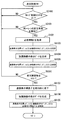
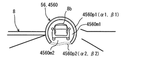
前方障害物の周囲のうち下方を除いた一周未満の範囲全域となる第一虚像表示位置において、余裕代(4560m1)をあけて前方障害物を囲む第一虚像表示サイズの第一線状部分(4560p1)、並びに前方障害物の周囲のうち第一線状部分の両端部間となる第二虚像表示位置において、余裕代(4560m2)をあけると共に第一線状部分よりも低輝度にて前方障害物を囲む第二虚像表示サイズの第二線状部分(4560p2)により、前方障害物を強調するための強調画像(4560)を、表示画像として記憶する画像記憶手段(54m)と、
少なくとも一つのプロセッサ(54p)により構築され、第一虚像表示位置及び第二虚像表示位置を含む虚像表示位置と、第一虚像表示サイズ及び第二虚像表示サイズを含む虚像表示サイズとを制御する虚像表示制御手段(S101,S102,S2100,S2101,S3100,S3101,S4103,S4104,S4105,S5101a,S5101b,S5102,S5103,S5104,S5105,S5203a,S5203b,S5204,S5205,S5303a,S5303b,S5303c,S5304,S5305,S5403a,S5403b,S6101,S6103,S6104,S6105,S6203,S7101,S7102,S7103a,S7103b,S7104,S7105)とを、備えることを特徴とする。
In addition, the second invention disclosed in order to solve the above-described problem is
Equipped with a HUD (50) that projects a display image (56) onto a projection member (21) that transmits through the outside scenery (8), thereby displaying a virtual image in association with the front obstacle (8b) in the outside scenery. In the host vehicle (2), the vehicle display control device (54, 50e) for controlling the virtual image display,
At the first virtual image display position that is the entire range of less than one round excluding the lower part of the periphery of the front obstacle, the first linear portion of the first virtual image display size surrounding the front obstacle with a margin (4560 m1) ( 4560p1), and at the second virtual image display position between both ends of the first linear portion around the front obstacle, a margin (4560 m2) is opened and the front obstacle is lower in brightness than the first linear portion. An image storage means (54m) for storing, as a display image, an enhanced image (4560) for emphasizing a front obstacle by a second linear portion (4560p2) of a second virtual image display size surrounding the object;
A virtual image constructed by at least one processor (54p) and controlling a virtual image display position including a first virtual image display position and a second virtual image display position, and a virtual image display size including a first virtual image display size and a second virtual image display size Display control means (S101, S102, S2100, S2101, S3100, S3101, S4103, S4104, S4105, S5101a, S5101b, S5102, S5103, S5104, S5105, S5203a, S5203b, S5204, S5205, S5303a, S5303b, S5303c, S5304, S5305, S5403a, S5403b, S6101, S6103, S6104, S6105, S6203, S7101, S7102, S7103a, S7103b, S7104, S7105) Characterized in that it comprises.
このような第二発明によると、外界風景中の前方障害物を強調する表示画像としての強調画像は、前方障害物の周囲のうち下方を除く一周未満範囲全域の虚像表示位置では、余裕代をあける第一線状部分により前方障害物を囲む虚像表示サイズに、制御される。故に、前方障害物の上方、左方及び右方にて外界風景中の空間に重畳する第一線状部分によれば、ユーザは、前方障害物に対するずれを感じても、前方障害物を指し示しているように見えるので、前方障害物に対する前後方向の離間を感じ難くなる。 According to the second invention as described above, the emphasized image as the display image for emphasizing the front obstacle in the outside scene has an allowance at the virtual image display position in the entire area of less than one round except the lower part around the front obstacle. The virtual image display size surrounding the front obstacle is controlled by the first linear portion. Therefore, according to the first linear portion that overlaps the space in the external scene above, to the left, and to the right of the front obstacle, the user points to the front obstacle even if the user feels a deviation from the front obstacle. It becomes difficult to feel the separation in the front-rear direction with respect to the front obstacle.
さらに第二発明によると、強調画像は、前方障害物の周囲のうち第一線状部分の両端部間となる虚像表示位置では、余裕代をあける第二線状部分により前方障害物を囲む虚像表示サイズに、制御される。ここで、前方障害物の下方に存在する地面に対して、第一線状部分よりも低輝度の第二線状部分が重畳しても、ユーザの注視点は第二線状部分側よりも第一線状部分側に集まり易い。故に、低輝度側の第二線状部分によれば、地面との関連付けが弱まるので、ユーザは、前方障害物に対する前後方向の離間を感じ難くなる。 Further, according to the second invention, the emphasized image is a virtual image that surrounds the front obstacle by the second linear portion with a margin at the virtual image display position between the both ends of the first linear portion around the front obstacle. Controlled by display size. Here, even if the second linear portion having a lower luminance than the first linear portion is superimposed on the ground existing below the front obstacle, the user's gaze point is more than the second linear portion side. Easy to gather on the first linear portion side. Therefore, according to the second linear portion on the low luminance side, since the association with the ground is weakened, the user is less likely to feel the separation in the front-rear direction with respect to the front obstacle.
こうしたことから、外乱等に起因する制御誤差の範囲で各線状部分の虚像表示位置がずれたとしても、前方障害物に対する強調画像の関連付けを維持でき、また前方障害物が離間しているかの如き錯覚も回避できる。しかも、各線状部分の虚像表示位置が制御誤差の範囲でずれたとしても、前方障害物の一部が強調画像に隠れることを、それら各線状部分のあける余裕代により回避して、ユーザの感じる煩わしさを抑制できる。以上、関連付けの維持作用及び錯覚の回避作用と共に、煩わしさの抑制作用を達成し得る第二発明によれば、強調画像の虚像表示により前方障害物を適正に強調可能となる。 For this reason, even if the virtual image display position of each linear part is deviated within the range of control error due to disturbance or the like, it is possible to maintain the association of the emphasized image with the front obstacle, and as if the front obstacle is separated. The illusion can also be avoided. In addition, even if the virtual image display position of each linear part is deviated within the range of the control error, the user feels that a part of the front obstacle is hidden in the emphasized image by the margin allowance of each linear part. Annoyance can be suppressed. As described above, according to the second invention that can achieve the bothersome maintenance action and illusion avoidance action and the annoyance suppressing action, it is possible to properly emphasize the front obstacle by displaying the virtual image of the emphasized image.
さらにまた、上述の課題を解決するために開示された第三発明としての車両用表示ユニットは、第一発明又は第二発明の車両用表示制御装置(54,50e)と、HUD50とを、備えることを特徴とする。
Furthermore, the vehicle display unit as the third invention disclosed in order to solve the above-described problems includes the vehicle display control device (54, 50e) of the first invention or the second invention, and the
このような第三発明では、HUDによる強調画像の虚像表示位置と虚像表示サイズとが第一発明又は第二発明の車両用表示制御装置により制御されることになるので、強調画像による前方障害物の強調を適正に行うことが可能となる。 In such a third invention, the virtual image display position and the virtual image display size of the emphasized image by the HUD are controlled by the vehicle display control device of the first invention or the second invention. Can be properly emphasized.
以下、本発明の複数の実施形態を図面に基づいて説明する。尚、各実施形態において対応する構成要素には同一の符号を付すことにより、重複する説明を省略する場合がある。各実施形態において構成の一部分のみを説明している場合、当該構成の他の部分については、先行して説明した他の実施形態の構成を適用することができる。また、各実施形態の説明において明示している構成の組み合わせばかりではなく、特に組み合わせに支障が生じなければ、明示していなくても複数の実施形態の構成同士を部分的に組み合せることができる。 Hereinafter, a plurality of embodiments of the present invention will be described with reference to the drawings. In addition, the overlapping description may be abbreviate | omitted by attaching | subjecting the same code | symbol to the corresponding component in each embodiment. When only a part of the configuration is described in each embodiment, the configuration of the other embodiment described above can be applied to the other part of the configuration. In addition, not only combinations of configurations explicitly described in the description of each embodiment, but also the configurations of a plurality of embodiments can be partially combined even if they are not explicitly specified unless there is a problem with the combination. .
(第一実施形態)
本発明が適用される第一実施形態の走行アシストシステム1は、図1,2に示すように、自車両2に搭載される。
(First embodiment)
A
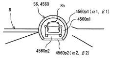
図2に示すように走行アシストシステム1は、周辺監視系3、車両制御系4及び表示系5から構成されている。これら走行アシストシステム1の各系3,4,5は、例えばLAN(Local Area Network)等の車内ネットワーク6を介して接続されている。
As shown in FIG. 2, the travel assist
周辺監視系3は、外界センサ30及び周辺監視ECU(Electronic Control Unit)31を備えている。外界センサ30は、自車両2の外界に存在して衝突する可能性のある障害物として例えば他車両、人工構造物、人間及び動物等や、外界に存在する交通表示を検知する。外界センサ30は、例えばソナー、レーダ及びカメラ等のうち、一種類又は複数種類である。
The
具体的にソナーは、自車両2のうち例えばフロント部又はリア部等に設置される超音波センサである。ソナーは、自車両2の外界のうち検知エリアへと送信した超音波の反射波を受信することで、当該検知エリア内の障害物を検知して検知信号を出力する。レーダは、自車両2のうち例えばフロント部若しくはリア部等に設置されるミリ波センサ、又はレーザセンサである。レーダは、自車両2の外界のうち検知エリアへと送信したミリ波若しくは準ミリ波、又はレーザの反射波を受信することで、当該検知エリア内の障害物を検知して検知信号を出力する。カメラは、自車両2のうち例えばルームミラー若しくはドアミラー等に設置される単眼式、又は複眼式のカメラである。カメラは、自車両2の外界のうち検知エリアを撮影することで、当該検知エリア内の障害物又は交通表示を検知して画像信号を出力する。
Specifically, the sonar is an ultrasonic sensor installed in, for example, a front part or a rear part of the
周辺監視ECU31は、プロセッサ及びメモリを有するマイクロコンピュータを主体として構成され、外界センサ30及び車内ネットワーク6に接続されている。周辺監視ECU31は、例えば制限速度標識及びレーン標識等といった標識情報、並びに白線及び黄線等といった区画線情報を、外界センサ30の出力信号に基づき取得する。それと共に周辺監視ECU31は、例えば障害物の種類、前方障害物8b(図1,4参照)の移動方向及び移動速度、並びに自車両2に対する前方障害物8bの相対速度及び相対距離等といった障害物情報を、外界センサ30の出力信号に基づき取得する。
The
車両制御系4は、車両状態センサ40、乗員センサ41及び車両制御ECU42を備えている。車両状態センサ40は、車内ネットワーク6に接続されている。車両状態センサ40は、自車両2の走行状態を検知する。車両状態センサ40は、例えば車速センサ、回転数センサ、舵角センサ、燃料センサ、水温センサ及び電波受信機等のうち、一種類又は複数種類である。
The
具体的に車速センサは、自車両2の車速を検知することで、当該検知に応じた車速信号を出力する。回転数センサは、自車両2におけるエンジン回転数を検知することで、当該検知に応じた回転数信号を出力する。舵角センサは、自車両2の舵角を検知することで、当該検知に応じた舵角信号を出力する。燃料センサは、自車両2の燃料タンクにおける燃料残量を検知することで、当該検知に応じた燃料信号を出力する。水温センサは、自車両2における内燃機関の冷却水温度を検知することで、当該検知に応じた水温信号を出力する。電波受信機は、例えば測位衛星、車車間通信用の他車両送信機、及び路車間通信用の路側機等からの出力電波を受信することで、交通信号を出力する。ここで交通信号は、例えば走行位置、走行方向、走行路状態及び制限速度等といった自車両2に関連する交通情報、並びに上記の障害物情報を表わす信号である。
Specifically, the vehicle speed sensor detects the vehicle speed of the
乗員センサ41は、車内ネットワーク6に接続されている。乗員センサ41は、図1に示す自車両2の車室2c内に搭乗したユーザの状態又は操作を検知する。乗員センサ41は、例えばパワースイッチ、ユーザ状態モニタ、表示設定スイッチ、ターンスイッチ、クルーズ制御スイッチ及びレーン制御スイッチ等のうち、一種類又は複数種類である。
The
具体的にパワースイッチは、自車両2の内燃機関又はモータジェネレータを始動させるために車室2c内にてユーザによりオン操作されることで、当該操作に応じたパワー信号を出力する。ユーザ状態モニタは、車室2c内にて運転席20上のユーザ状態を画像センサにより撮影することで、当該ユーザ状態を検知して画像信号を出力する。表示設定スイッチは、車室2c内にて表示状態を設定するためにユーザにより操作されることで、当該操作に応じた表示設定信号を出力する。ターンスイッチは、自車両2の方向指示器を作動させるために車室2c内にてユーザによりオン操作されることで、当該操作に応じたターン信号を出力する。
Specifically, the power switch is turned on by the user in the
クルーズ制御スイッチは、前方障害物8bとしての前方車両に対する自車両2の車間距離又は自車両2の車速を自動制御するために、車室2c内にてユーザによりオン操作されることで、当該操作に応じたクルーズ制御信号を出力する。レーン制御スイッチは、自車両2の走行レーンにおける幅方向位置を自動制御するために、車室2c内にてユーザによりオン操作されることで、当該操作に応じたレーン制御信号を出力する。
The cruise control switch is turned on by the user in the
図2に示す車両制御ECU42は、プロセッサ及びメモリを有するマイクロコンピュータを主体として構成され、車内ネットワーク6に接続されている。車両制御ECU42は、エンジン制御ECU、モータ制御ECU、ブレーキ制御ECU、ステアリング制御ECU及び統合制御ECU等のうち、統合制御ECUを少なくとも含む一種類又は複数種類である。
The
具体的にエンジン制御ECUは、内燃機関のスロットルアクチュエータや燃料噴射弁の作動を、図1に示す車室2c内でのアクセルペダル26の操作に従って又は自動で制御することで、自車両2の車速を加減速する。モータ制御ECUは、モータジェネレータの作動を、車室2c内でのアクセルペダル26の操作に従って又は自動で制御することで、自車両2の車速を加減速する。ブレーキ制御ECUは、ブレーキアクチュエータの作動を、車室2c内でのブレーキペダル27の操作に従って又は自動で制御することで、自車両2の車速を加減速する。ステアリング制御ECUは、電動パワーステアリングの作動を、車室2c内でのステアリングハンドル24の操作に従って自動で制御することで、自車両2の舵角を調整する。統合制御ECUは、例えば車両制御ECU42のうち他制御ECUでの制御情報、センサ40,41の出力信号、及び周辺監視ECU31での取得情報等に基づき、当該他制御ECUの作動を同期制御する。
Specifically, the engine control ECU controls the operation of the throttle actuator and the fuel injection valve of the internal combustion engine in accordance with the operation of the
特に本実施形態の統合制御ECUは、クルーズ制御スイッチがオン操作された場合に、自車両2の全車速域での車間距離及び車速を自動で制御する全車速域アダプティブクルーズコントロール(FSRA:Full Speed Range Adaptive Cruise Control)を、実現する。このFSRAを実現する「車間制御ユニット」として自車両2に搭載された統合制御ECUは、周辺監視ECU31での取得情報及び電波受信機の出力信号に基づき、エンジン制御ECU又はモータ制御ECUの作動と、ブレーキ制御ECUの作動とを制御する。
In particular, the integrated control ECU according to the present embodiment performs full vehicle speed range adaptive cruise control (FSRA: Full Speed) that automatically controls the inter-vehicle distance and vehicle speed in the entire vehicle speed range of the
また、本実施形態の統合制御ECUは、レーン制御スイッチがオン操作された場合に、白線又は黄線からの自車両2の逸脱を規制して走行レーンにおける幅方向位置を自動で制御するレーンキーピングアシスト(LKA:Lane Keeping Assist)を、実現する。このLKAを実現する「レーン制御ユニット」としても自車両2に搭載された統合制御ECUは、周辺監視ECU31での取得情報及び電波受信機の出力信号に基づき、ステアリング制御ECUの作動を制御する。
Further, the integrated control ECU according to the present embodiment automatically controls the position in the width direction in the traveling lane by regulating the deviation of the
「車両用表示ユニット」としての表示系5は、情報を視覚提示するために自車両2に搭載されている。表示系5は、HUD50、MFD(Multi Function Display)51、コンビネーションメータ52及びHCU(HMI(Human Machine Interface) Control Unit)54を備えている。
A
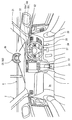
HUD50は、図1,3に示す車室2c内にてインストルメントパネル22に設置されている。HUD50は、例えば液晶パネル又はプロジェクタ等の表示器50iにて所定情報を示すように形成した表示画像56を、自車両2における「投影部材」としてのフロントウインドシールド21に対して、光学系50oを通して投影する。ここでフロントウインドシールド21は、透光性ガラスにより形成されることで、車室2c外のうち自車両2の前方に存在する外界風景8を透過させる。このとき、フロントウインドシールド21で反射した表示画像56の光束と、同シールド21を透過した外界風景8からの光束とが、運転席20上のユーザにより知覚される。その結果、フロントウインドシールド21よりも前方に結像される表示画像56の虚像が外界風景8の一部に重畳して表示されることで、それら表示画像56の虚像と外界風景8とが運転席20上のユーザにより視認可能となっている。
The
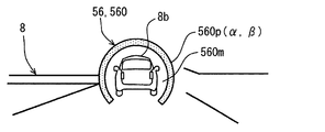
ここで、図4に示すように本実施形態では、外界風景8中の前方障害物8bを強調するために、表示画像56としての強調画像560が虚像表示される。具体的に強調画像560は、虚像表示位置αにおいて円弧形に湾曲して延びる一定幅の線状部分560pを、全体として形成している。線状部分560pの虚像表示サイズβは、前方障害物8bの周囲のうち下方を除いた一周未満の範囲全域となる虚像表示位置αにおいて、前方障害物8bを連続して囲むように可変設定される。それと共に、線状部分560pの虚像表示サイズβは、前方障害物8b以外の外界風景8を直接ユーザに視認させるための余裕代560mを、内周側の前方障害物8bとの間にあけるように可変設定される。さらに、線状部分560pの虚像表示色は、外界風景8との重畳部分の視認を可能にし且つユーザの煩わしさを抑制可能な半透明色のうち、前方障害物8bを強調してユーザへの注意喚起を可能にする高輝度の所定色調に、固定設定又はユーザにより可変設定される。例えば線状部分560pの虚像表示色は、明黄色、明赤色、明緑色又はライトアンバー色等に設定される。
Here, as shown in FIG. 4, in the present embodiment, the emphasized image 560 as the display image 56 is displayed as a virtual image in order to emphasize the
尚、HUD50による虚像表示としては、こうした強調画像560の表示に追加して、例えばナビゲーション情報、標識情報及び障害物情報等のうち、一種類又は複数種類の情報を示す画像の表示を採用してもよい。また、インストルメントパネル22に配置されてフロントウインドシールド21と共同して外界風景8を透過させる透光性コンバイナを用いることで、当該コンバイナに表示画像56を投影することによっても、虚像表示の実現が可能である。さらにまた、上記のナビゲーション情報は、例えば後に詳述するHCU54において、メモリ54mに記憶の地図情報と、センサ40の出力信号とに基づき取得可能である。
As a virtual image display by the
MFD51は、図1に示す車室2c内にてセンターコンソール23に設置される。MFD51は、一つ又は複数の液晶パネルにて所定情報を示すように形成した画像の実像を、運転席20上のユーザにより視認可能に表示する。こうしたMFD51による実像表示としては、ナビゲーション情報、オーディオ情報、映像情報及び通信情報等のうち、一種類又は複数種類の情報を示す画像の表示が採用される。
The
コンビネーションメータ52は、車室2c内にてインストルメントパネル22に設置される。コンビネーションメータ52は、自車両2に関する車両情報を、運転席20上のユーザにより視認可能に表示する。コンビネーションメータ52は、液晶パネルに形成した画像により車両情報を表示するデジタルメータ、又は指針により目盛を指示して車両情報を表示するアナログメータである。こうしたコンビネーションメータ52による表示としては、例えば車速、エンジン回転数、燃料残量、冷却水温度、並びにターンスイッチ、クルーズ制御スイッチ及びレーン制御スイッチの操作状態等のうち、一種類又は複数種類の情報を示す表示が採用される。
The
図2に示すHCU54は、プロセッサ54p及びメモリ54mを有するマイクロコンピュータを主体として構成され、表示系5の表示要素50,51,52及び車内ネットワーク6に接続されている。HCU54は、表示要素50,51,52の作動を同期制御する。このときHCU54は、例えばセンサ40,41の出力信号、ECU31での取得情報、ECU42での制御情報、メモリ54mの記憶情報、並びにHCU54自身での取得情報等に基づき、それらの作動制御を実行する。尚、HCU54のメモリ54m及び他の各種ECUのメモリは、例えば半導体メモリ、磁気媒体若しくは光学媒体等といった記憶媒体を、一つ又は複数使用してそれぞれ構成される。
The HCU 54 shown in FIG. 2 is mainly composed of a microcomputer having a
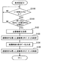
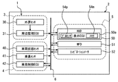
ここで特に本実施形態では、強調画像560を含む表示画像56のデータが「画像記憶手段」としてのメモリ54mに記憶されることで、HCU54が「車両用表示制御装置」として機能する。具体的にHCU54は、プロセッサ54pにより表示制御プログラムを実行することで、強調画像560をメモリ54mから読み出して表示する表示制御フローを、図5に示すように実現する。尚、表示画像56を記憶させる「画像記憶手段」については、表示要素50,51,52の内蔵ECUの各メモリのうちいずれかにより、又はそれら各メモリ及びHCU54のメモリ54mのうち複数メモリの共同により、実現しても勿論よい。また、表示制御フローは、乗員センサ41のうちパワースイッチのオン操作に応じて開始され、同スイッチのオフ操作に応じて終了する。さらにまた、表示制御フロー中の「S」とは、各ステップを意味する。
Here, particularly in the present embodiment, the data of the display image 56 including the emphasized image 560 is stored in the
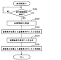
表示制御フローのS101では、強調画像560により強調して注意喚起する前方障害物8bを一つ検知したか否かを、判定する。具体的にS101での判定は、例えば周辺監視ECU31により取得された障害物情報、及び乗員センサ41である電波受信機の出力信号が表す障害物情報等のうち、一種類又は複数種類に基づき下される。こうしたS101にて否定判定が下される間は、S101を繰り返して実行する一方、同S101にて肯定判定が下された場合には、S102へと移行する。
In S <b> 101 of the display control flow, it is determined whether or not one
続くS102では、強調画像560を虚像表示するための必要情報Iを、取得する。具体的に必要情報Iは、例えば周辺監視ECU31での取得情報、及びセンサ40,41の出力信号に基づく情報のうち、一種類又は複数種類である。ここで周辺監視ECU31での取得情報としては、障害物情報が例示される。車両状態センサ40の出力信号に基づく情報としては、車速センサの出力信号が表す車速、及び舵角センサの出力信号が表す舵角が例示される。乗員センサ41に基づく情報としては、表示設定スイッチの出力信号が表す表示状態の設定値、ユーザ状態モニタの出力信号が表す眼球状態等のユーザ状態、並びに電波受信機の出力信号が表す交通情報及び障害物情報が例示される。
In subsequent S102, necessary information I for displaying the emphasized image 560 as a virtual image is acquired. Specifically, the necessary information I is, for example, one type or a plurality of types of information obtained from the
続くS103では、S102にて取得された必要情報Iに基づき、強調画像560の虚像表示位置αと虚像表示サイズβとを設定する。具体的には、まず、S101により検知された前方障害物8bをユーザが注視したときの注視点又は注視線を、必要情報Iに基づき推定する。次に、推定された注視点又は注視線上の前方障害物8bに対して下方を除く一周未満の範囲全域となるように、虚像表示位置αを設定し、且つ同障害物8bに対して余裕代560mをあける線状部分560pを形成するように、虚像表示サイズβを設定する。
In the subsequent S103, the virtual image display position α and the virtual image display size β of the emphasized image 560 are set based on the necessary information I acquired in S102. Specifically, first, based on the necessary information I, the gaze point or gaze line when the user gazes at the
続くS104では、S103にて設定された虚像表示位置α及び虚像表示サイズβをもって強調画像560を虚像表示させるための表示データを、生成する。このとき表示データは、メモリ54mから読み出した強調画像560のデータに対して画像処理を施すことで、生成される。
In subsequent S104, display data for displaying the emphasized image 560 in a virtual image with the virtual image display position α and the virtual image display size β set in S103 is generated. At this time, the display data is generated by performing image processing on the data of the emphasized image 560 read from the
続くS105では、S104にて生成された表示データをHUD50に与えて、表示器50iにより強調画像560を形成することで、線状部分560pの虚像表示位置αと虚像表示サイズβとを制御する。その結果、図1,4の如く強調画像560は、前方障害物8bの周囲のうち下方を除いた一周未満範囲全域の虚像表示位置αにおいて、線状部分560pにより余裕代560mをあけて前方障害物8bを囲む虚像表示サイズβに、視認される。尚、以上の後に表示制御フローでは、S101へと戻る。その結果、戻った直後のS101にて否定判定が下された場合には、強調画像560の虚像表示は終了することになる。
In subsequent S105, the display data generated in S104 is given to the
尚、このような第一実施形態では、HCU54のうちS101,S102,S103,S104,S105を実行する部分が、プロセッサ54pにより構築される「虚像表示制御手段」に相当する。
In such a first embodiment, the portion of the HCU 54 that executes S101, S102, S103, S104, and S105 corresponds to “virtual image display control means” constructed by the
(作用効果)
ここまで説明した第一実施形態の作用効果を、以下に説明する。
(Function and effect)
The operational effects of the first embodiment described so far will be described below.
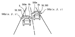
外界風景8中の前方障害物8bを強調する強調画像560は、前方障害物8bの周囲のうち下方を除く一周未満範囲全域の虚像表示位置αでは、余裕代560mをあける線状部分560pにより前方障害物8bを囲む虚像表示サイズβに、制御される。故に、図6に示すように、前方障害物8bの上方、左方及び右方にて外界風景8中の空間8sに重畳する強調画像560によれば、ユーザは、前方障害物8bに対するずれを感じても、前方障害物8bを指し示しているように見えるので、前方障害物8bに対する前後方向の離間を感じ難くなる。
The emphasis image 560 that emphasizes the
こうしたことから、制御誤差の範囲で強調画像560の虚像表示位置αがずれたとしても、前方障害物8bに対する強調画像560の関連付けを維持でき、また前方障害物8bが離間しているかの如き錯覚も回避できる。しかも、強調画像560の虚像表示位置αが制御誤差の範囲でずれたとしても、前方障害物8bの一部が強調画像560に隠れることを、線状部分560pのあける余裕代560mにより回避して、ユーザの感じる煩わしさを抑制できる。以上、関連付けの維持作用及び錯覚の回避作用と共に、煩わしさの抑制作用を達成し得る第一実施形態によれば、強調画像560の虚像表示により前方障害物8bを適正に強調可能となる。
For this reason, even if the virtual image display position α of the emphasized image 560 is deviated within the range of the control error, the association of the emphasized image 560 with the
また、虚像表示位置αにて円弧形に延びる線状部分560pの両端部間では、図6に示すように、当該線状部分560pを補完する円弧形の仮想線状部分560v(同図の二点鎖線参照)をユーザは、前方障害物8bの下方にもイメージし得る。即ちユーザは、前方障害物8bの下方にある地面8gに重ねて、仮想線状部分560vをイメージし得る。故に、実際には前方障害物8bの下方に虚像表示されないことで地面8gとの関連付けが弱まる強調画像560に対して、仮想線状部分560vがイメージ上にて加わることになる。これによれば、前方障害物8bに対する強調画像560の前後方向の離間をユーザには感じさせ難くしつつも、前方障害物8bに対する強調画像560の関連付けを強化できるので、前方障害物8bの強調効果を高めることが可能となる。
Further, between both ends of the
以上のことから、HUD50による強調画像560の虚像表示位置αと虚像表示サイズβとがHCU54により制御されることによれば、強調画像560による前方障害物8bの強調を適正に行うことが可能である。
From the above, by controlling the virtual image display position α and the virtual image display size β of the emphasized image 560 by the
(第二実施形態)
本発明の第二実施形態は、第一実施形態の変形例である。図7に示すように、第二実施形態の表示制御フローでは、乗員センサ41のうちクルーズ制御スイッチがオンされているか否かを、S2100にて判定する。その結果、否定判定が下される間は、S2100を繰り返して実行する一方、肯定判定が下された場合には、S2101へと移行する。
(Second embodiment)
The second embodiment of the present invention is a modification of the first embodiment. As shown in FIG. 7, in the display control flow of the second embodiment, it is determined in S2100 whether or not the cruise control switch of the
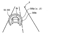
S2101では、車両制御ECU42のうち統合制御ECUがFSRAによる車間距離の自動制御下、自車両2と同一レーンを同一方向へと走行する直近一台の前方車両を、前方障害物8bとして検知したか否かを判定する。具体的にS2101での判定は、例えば統合制御ECUの制御情報、電波受信機の出力信号が表す障害物情報、並びに周辺監視ECU31により取得された標記情報、区画線情報及び障害物情報等のうち、一種類又は複数種類に基づき下される。こうしたS2101にて否定判定が下される間は、S2100へと戻る一方、同S2101にて肯定判定が下された場合には、S102,S103,S104,S105の実行後に、S2100へと戻る。尚、S105から戻った直後のS2100又はS2101にて否定判定が下された場合には、強調画像560の虚像表示は終了することになる。
In step S2101, whether the integrated control ECU of the
このように第二実施形態では、第一実施形態と同様にして、前方障害物8bとしての前方車両に対して自車両2の車間距離が自動制御される。故に、図8に示す如く強調画像560の位置α及びサイズβが制御されることによれば、車間距離の自動制御下にてユーザの注意が必要な同一レーンの前方車両に対する強調を適正なものとして、ユーザの安全と安心とを確保することが可能となる。尚、以上の第二実施形態では、HCU54のうちS2100,S2101,S102,S103,S104,S105を実行する部分が、プロセッサ54pにより構築される「虚像表示制御手段」に相当する。
As described above, in the second embodiment, the inter-vehicle distance of the
(第三実施形態)
本発明の第三実施形態は、第一実施形態の変形例である。図9に示すように、第三実施形態の表示制御フローでは、乗員センサ41のうちレーン制御スイッチがオンされているか否かを、S3100にて判定する。その結果、否定判定が下される間は、S3100を繰り返して実行する一方、肯定判定が下された場合には、S3101へと移行する。
(Third embodiment)
The third embodiment of the present invention is a modification of the first embodiment. As shown in FIG. 9, in the display control flow of the third embodiment, it is determined in S3100 whether or not the lane control switch of the
S3101では、車両制御ECU42のうち統合制御ECUがLKAによる自動制御下、自車両2の走行レーンと同一又は別のレーンを同一方向へと走行する直近一台の前方車両につき、前方障害物8bとして検知したか否かを判定する。具体的にS3101での判定は、統合制御ECUの制御情報、電波受信機の出力信号が表す障害物情報、並びに周辺監視ECU31により取得された標記情報、区画線情報及び障害物情報等のうち、一種類又は複数種類に基づき下される。こうしたS3101にて否定判定が下される間は、S3100へと戻る一方、同S3101にて肯定判定が下された場合には、S102,S103,S104,S105の実行後に、S3100へと戻る。尚、S105から戻った直後のS3100又はS3101にて否定判定が下された場合には、強調画像560の虚像表示は終了することになる。
In S3101, the integrated control ECU of the
このように第三実施形態では、第一実施形態と同様にして、自車両2の走行レーンにおける幅方向位置が自動制御される。故に、図10に示す如く強調画像560の位置α及びサイズβが制御されることによれば、幅方向位置の自動制御下にてユーザの注意が必要な同一又は別レーンの前方車両に対する強調を適正なものとして、ユーザの安全と安心とを確保することが可能となる。尚、以上の第三実施形態では、HCU54のうちS3100,S3101,S102,S103,S104,S105を実行する部分が、プロセッサ54pにより構築される「虚像表示制御手段」に相当する。
Thus, in the third embodiment, the position in the width direction in the travel lane of the
(第四実施形態)
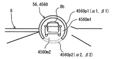
本発明の第四実施形態は、第一実施形態の変形例である。図11に示すように第四実施形態では、外界風景8中の前方障害物8bを強調する表示画像56として、第一実施形態とは異なる強調画像4560がメモリ54mに記憶されて虚像表示される。具体的に強調画像4560は、第一虚像表示位置α1において円弧形に湾曲して延びる第一線状部分4560p1と、第二虚像表示位置α2において円弧形に湾曲して延びる第二線状部分4560p2とを、同一幅に連続して形成している。即ち強調画像4560は、全体としては円環線状を呈している。
(Fourth embodiment)
The fourth embodiment of the present invention is a modification of the first embodiment. As shown in FIG. 11, in the fourth embodiment, as the display image 56 that emphasizes the
ここで、第一線状部分4560p1のサイズである第一虚像表示サイズβ1は、前方障害物8bの周囲のうち下方を除いた一周未満の範囲全域となる第一虚像表示位置α1にて、前方障害物8bを連続して囲むように可変設定される。それと共に、第一線状部分4560p1の虚像表示サイズβ1は、前方障害物8b以外の外界風景8を直接ユーザに視認させるための余裕代4560m1を、内周側の前方障害物8bとの間にあけるように可変設定される。さらに、第一線状部分4560p1の虚像表示色は、外界風景8との重畳部分の視認を可能にし且つ煩わしさを抑制可能な半透明色のうち、前方障害物8bを強調してユーザへの注意喚起を可能にする高輝度の所定色調に、固定設定又はユーザにより可変設定される。例えば第一線状部分4560p1の虚像表示色は、明黄色、明赤色、明緑色又はライトアンバー色等に設定される。
Here, the first virtual image display size β1 that is the size of the first linear portion 4560p1 is the first virtual image display position α1 that is the entire range of less than one round except the lower part of the periphery of the
一方、第二線状部分4560p2のサイズである第二虚像表示サイズβ2は、前方障害物8bの周囲のうち下方にて第一線状部分4560p1の両端部間となる第二虚像表示位置α2にて、前方障害物8bを連続して囲むように可変設定される。それと共に、第二線状部分4560p2の虚像表示サイズβ1は、前方障害物8b以外の外界風景8を直接ユーザに視認させるための余裕代4560m2を、内周側の前方障害物8bとの間にあけるように可変設定される。さらに、第二線状部分4560p2の虚像表示色は、外界風景8との重畳部分の視認を可能にし且つ煩わしさを抑制可能な半透明色のうち、第一線状部分4560p1よりも低輝度の所定色調に、固定設定又はユーザにより可変設定される。例えば第二線状部分4560p2の虚像表示色は、暗黄色、暗赤色、暗緑色又はダークアンバー色等に設定される。尚、各線状部分4560p1,4560p2の色調については、同系統に設定してもよいし、異系統に設定してもよい。また、各線状部分4560p1,4560p2の輝度については、例えば第一線状部分4560p1よりも第二線状部分4560p2にて輝度信号の輝度値が低下するように、各線状部分4560p1,4560p2の階調値を設定することで調整される。
On the other hand, the second virtual image display size β2 which is the size of the second linear portion 4560p2 is set at the second virtual image display position α2 between the both ends of the first linear portion 4560p1 in the lower part around the
図12に示すように、こうした第四実施形態の表示制御フローでは、第一実施形態と同様なS101,S102の実行後のS4103にて、強調画像560の虚像表示位置α1,α2と虚像表示サイズβ1,β2とを、S102での取得情報Iに基づき設定する。具体的には、まず、S101により検知された前方障害物8bをユーザが注視したときの注視点又は注視線を、必要情報Iに基づき推定する。次に、推定された注視点又は注視線上の前方障害物8bに対して下方を除く範囲全域に、第一虚像表示位置α1を設定し、且つ同障害物8bに対して余裕代4560m1をあける第一線状部分4560p1を形成するように、第一虚像表示サイズβ1を設定する。それと共に、推定された注視点又は注視線上の前方障害物8bに対して下方となる第一線状部分4560p1の両端部間に、第二虚像表示位置α2を設定し、且つ同障害物8bに対して余裕代4560m2をあける第二線状部分4560p2を形成するように、第二虚像表示サイズβ2を設定する。
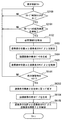
As shown in FIG. 12, in the display control flow of the fourth embodiment, the virtual image display positions α1 and α2 of the emphasized image 560 and the virtual image display size in S4103 after the execution of S101 and S102 similar to the first embodiment. β1 and β2 are set based on the acquired information I in S102. Specifically, first, based on the necessary information I, the gaze point or gaze line when the user gazes at the
続くS4104では、S4103で設定された虚像表示位置α1,α2及び虚像表示サイズβ1,β2をもって各線状部分4560p1,4560p2を虚像表示させるための表示データを、生成する。このとき表示データは、メモリ54mから読み出した強調画像4560のデータに画像処理を施すことで、生成される。
In subsequent S4104, display data for displaying the linear portions 4560p1 and 4560p2 in a virtual image with the virtual image display positions α1 and α2 and the virtual image display sizes β1 and β2 set in S4103 is generated. At this time, the display data is generated by performing image processing on the data of the emphasized image 4560 read from the
続くS4105では、S4104にて生成された表示データをHUD50に与えて、表示器50iにより強調画像4560を形成することで、各線状部分4560p1,4560p2の虚像表示位置α1,α2と虚像表示サイズβ1,β2とを制御する。その結果として強調画像4560は、前方障害物8bの周囲のうち下方を除いた一周未満範囲全域の第一虚像表示位置α1では、第一線状部分4560p1により余裕代4560m1をあけて前方障害物8bを囲む第一虚像表示サイズβ1に、視認される。それと共に強調画像4560は、前方障害物8bの周囲のうち下方の第二虚像表示位置α2では、第一線状部分4560p1より低輝度の第二線状部分4560p2により、余裕代4560m2をあけて前方障害物8bを囲む第二虚像表示サイズβ2に、視認される。尚、以上の後に表示制御フローでは、S101へと戻る。ここで、戻った直後のS101にて否定判定が下された場合には、強調画像4560の虚像表示は終了することになる。
In subsequent S4105, the display data generated in S4104 is given to the
尚、このような第四実施形態では、HCU54のうちS101,S102,S4103,S4104,S4105を実行する部分が、プロセッサ54pにより構築される「虚像表示制御手段」に相当する。
In the fourth embodiment, the portion of the HCU 54 that executes S101, S102, S4103, S4104, and S4105 corresponds to “virtual image display control means” constructed by the
(作用効果)
ここまで説明した第四実施形態の作用効果を、以下に説明する。
(Function and effect)
The effects of the fourth embodiment described so far will be described below.
前方障害物8bを強調する強調画像4560は、前方障害物8bの周囲のうち下方を除く一周未満範囲全域の第一虚像表示位置α1では、余裕代4560m1をあける第一線状部分4560p1により前方障害物8bを囲む虚像表示サイズβ1に、制御される。故に、図13に示すように、前方障害物8bの上方、左方及び右方にて外界風景8の空間4008sに重畳する第一線状部分4560p1によれば、ユーザは、前方障害物8bに対するずれを感じても、前方障害物8bを指し示しているように見えるので、前方障害物8bに対する前後方向の離間を感じ難くなる。
The emphasized image 4560 that emphasizes the
さらに強調画像4560は、前方障害物8bの周囲のうち第一線状部分4560p1の両端部間となる第二虚像表示位置α2では、余裕代4560m2をあける第二線状部分4560p2により前方障害物8bを囲む虚像表示サイズβ2に、制御される。ここで図13に示すように、前方障害物8bの下方に存在する地面4008gに対して、第一線状部分4560p1より低輝度の第二線状部分4560p2が重畳しても、ユーザの注視点は第二線状部分4560p2側より第一線状部分4560p1側に集まり易い。故に、低輝度側の第二線状部分4560p2によれば、地面4008gとの関連付けが弱まるので、ユーザは、前方障害物8bに対する前後方向の離間を感じ難くなる。
Further, the emphasized image 4560 is displayed at the second virtual image display position α2 between the both ends of the first linear portion 4560p1 in the periphery of the
こうしたことから、制御誤差の範囲で各線状部分4560p1,4560p2の虚像表示位置α1,α2がずれたとしても、前方障害物8bに対する強調画像4560の関連付けを維持でき、また前方障害物8bが離間しているかの如き錯覚も回避できる。しかも、各線状部分4560p1,4560p2分の虚像表示位置α1,α2が制御誤差の範囲でずれたとしても、前方障害物8bの一部が強調画像4560に隠れることを、それら各線状部分4560p1,4560p2のあける余裕代4560m1,4560m2により回避して、ユーザの感じる煩わしさを抑制できる。以上、関連付けの維持作用及び錯覚の回避作用と共に、煩わしさの抑制作用を達成し得る第四実施形態によれば、強調画像4560の虚像表示により前方障害物8bを適正に強調可能となる。
Therefore, even if the virtual image display positions α1 and α2 of the linear portions 4560p1 and 4560p2 are shifted within the range of the control error, the association of the emphasized image 4560 with the
また、第二虚像表示位置α2にて第一線状部分4560p1の両端部間を湾曲して延びる第二線状部分4560p2については、地面4008gに重畳したとしても、低輝度によりユーザの注視点が集まり難いだけでなく、ユーザには水平線を想起させ難い。故に、各線状部分4560p1,4560p2の虚像表示位置α1,α2が制御誤差の範囲でずれた場合には、前方障害物8bの下方にあっても第二線状部分4560p2の地面4008gとの関連付けが弱まるので、当該部分4560p2から注視点を逸らし得る。これによれば、関連付けの維持作用及び錯覚の回避作用を確実に発揮し得るので、前方障害物8bを適正に強調可能となる。
In addition, even if the second linear portion 4560p2 that curves and extends between both ends of the first linear portion 4560p1 at the second virtual image display position α2, even if the second linear portion 4560p2 is superimposed on the
以上のことから、HUD50による強調画像4560の虚像表示位置α1,α2と虚像表示サイズβ1,β2とがHCU54により制御されることによれば、強調画像4560による前方障害物8bの強調を適正に行うことが可能である。
From the above, when the virtual image display positions α1 and α2 and the virtual image display sizes β1 and β2 of the enhanced image 4560 by the
(第五実施形態)
本発明の第五実施形態は、第一実施形態の変形例である。図14に示すように、第五実施形態の表示制御フローでは、S101に代えて、S5101a,S5101bを実行する。
(Fifth embodiment)
The fifth embodiment of the present invention is a modification of the first embodiment. As shown in FIG. 14, in the display control flow of the fifth embodiment, S5101a and S5101b are executed instead of S101.
S5101aでは、強調画像560により強調して注意喚起する前方障害物8bを少なくとも一つ検知したか否かを、判定する。このときの判定は、S101と同様にして下される。こうしたS5101aにて否定判定が下される間は、S5101aを繰り返して実行する一方、同S5101aにて肯定判定が下された場合には、S5101bへと移行する。
In S5101a, it is determined whether or not at least one
S5101bでは、S101にて検知された前方障害物8bが複数であるか否かを、判定する。その結果、否定判定が下された場合には、単独の前方障害物8bに対する処理としてS102,S103,S104,S105を実行する。一方、肯定判定が下された場合には、各前方障害物8b毎の個別処理としてS5102,S5103,S5104,S5105を実行する。
In S5101b, it is determined whether there are a plurality of
S5102では、強調画像560を虚像表示するための必要情報Iを、S101にて検知された前方障害物8b毎に個別に取得する。このとき、前方障害物8b毎の必要情報Iは、S102と同様に取得される。
In S5102, the necessary information I for displaying the emphasized image 560 as a virtual image is individually acquired for each
続くS5103では、強調画像560の虚像表示位置αと虚像表示サイズβとを、S101にて検知された前方障害物8b毎に個別に設定する。このとき、S5102にて取得された前方障害物8b毎の必要情報Iに基づくことで、図15に示すように虚像表示サイズβは、強調画像560により強調する前方障害物8bが自車両2から遠いほど、小サイズとなるように設定される。これ以外の点について虚像表示位置α及び虚像表示サイズβは、S103と同様に設定される。
In subsequent S5103, the virtual image display position α and the virtual image display size β of the emphasized image 560 are individually set for each
続くS5104では、図14に示すように、S5103にて設定された虚像表示位置α及び虚像表示サイズβをもって強調画像560を虚像表示させるための表示データを、S101にて検知された前方障害物8b毎に個別に生成する。このとき、前方障害物8b毎の表示データは、S104と同様に生成される。
In subsequent S5104, as shown in FIG. 14, display data for displaying the emphasized image 560 with the virtual image display position α and virtual image display size β set in S5103 is displayed as the
続くS5105では、S5104にて生成された表示データをHUD50に与えて、表示器50iにより強調画像560を形成する。これにより、強調画像560の線状部分560pの虚像表示位置αと虚像表示サイズβとを、S101にて検知された前方障害物8b毎に個別に制御する。その結果、図15の如く前方障害物8b毎の各強調画像560は、S105と同様な虚像表示位置αでの虚像表示サイズβに加え、強調画像560により強調する前方障害物8bが自車両2から遠いほど小サイズとなる虚像表示サイズβに、視認される。
In subsequent S5105, the display data generated in S5104 is given to the
こうしたS5105の実行後に表示制御フローでは、S5101aへと戻る。その結果、戻った直後のS5101aにて否定判定が下された場合には、全ての強調画像560の虚像表示が終了する。また、戻った直後のS5101aにて肯定判定且つS5101bにて否定判定が下された場合、検知されなくなった前方障害物8bに対する強調画像560の虚像表示は終了するが、検知されたままの前方障害物8bに対する強調画像560の虚像表示は継続される。尚、S105の実行後にも、S5101aへと戻る。
In the display control flow after execution of S5105, the process returns to S5101a. As a result, if a negative determination is made in S5101a immediately after returning, the virtual image display of all the emphasized images 560 ends. In addition, when an affirmative determination is made in S5101a immediately after returning and a negative determination is made in S5101b, the virtual image display of the emphasized image 560 for the
このように第五実施形態によると、複数の前方障害物8bをそれぞれ個別に強調する強調画像560は、強調する前方障害物8bが自車両2から遠いほど、小サイズに制御される。これによれば、自車両2に近いことで特に注意の必要な前方障害物8bに対しては、大サイズの強調画像560により強調度合いを高めつつ、自車両2から遠い前方障害物8bに対しても、小サイズの強調画像560により強調機能を確保できる。故に、個別の強調画像560による複数障害物8bの強調を、メリハリを付けて適正に行うことが可能となる。尚、以上の第五実施形態では、HCU54のうちS5101a,S5101b,S102,S103,S104,S105,S5102,S5103,S5104,S5105を実行する部分が、プロセッサ54pにより構築される「虚像表示制御手段」に相当する。
As described above, according to the fifth embodiment, the emphasized image 560 that individually emphasizes the plurality of
(第六実施形態)
本発明の第六実施形態は、第五実施形態の変形例である。図16に示すように、第六実施形態の表示制御フローでは、S5102の実行後に、S5203a,S5203b,S5204,S5205を実行する。
(Sixth embodiment)
The sixth embodiment of the present invention is a modification of the fifth embodiment. As shown in FIG. 16, in the display control flow of the sixth embodiment, S5203a, S5203b, S5204, and S5205 are executed after the execution of S5102.
S5203aでは、強調画像560の虚像表示位置αと虚像表示サイズβとを、S101にて検知された前方障害物8b毎に個別に設定する。このとき虚像表示位置α及び虚像表示サイズβは、S5103と同様に設定される。
In S5203a, the virtual image display position α and the virtual image display size β of the emphasized image 560 are individually set for each
続くS5203bでは、強調画像560の虚像表示形状γを、S101にて検知された前方障害物8b毎に個別に設定する。このとき、S5102にて取得された必要情報Iのうち、障害物情報である前方障害物8bの種類に応じて、図17に示すように各強調画像560での線状部分560pの虚像表示形状γが異ならされる。ここで図17の例では、他車両である前方障害物8bに対して、線状部分560pの虚像表示形状γが円弧形としての部分真円形に設定されている。それと共に図17の例では、人間である前方障害物8bに対して、線状部分560pの虚像表示形状γが円弧形としての部分楕円形に設定されている。
In subsequent S5203b, the virtual image display shape γ of the emphasized image 560 is individually set for each
続くS5204では、図16に示すように、S5203aにて設定された虚像表示位置α及び虚像表示サイズβに加え、S5203bにて設定された虚像表示形状γをもって強調画像560を虚像表示させるための表示データを、生成する。このとき表示データは、S5104と同様に、メモリ54mから読み出した強調画像560のデータに対して画像処理を施すことで、S101にて検知された前方障害物8b毎に個別に生成される。
In subsequent S5204, as shown in FIG. 16, in addition to the virtual image display position α and the virtual image display size β set in S5203a, a display for virtual image display of the enhanced image 560 with the virtual image display shape γ set in S5203b. Generate data. At this time, display data is individually generated for each
続くS5205では、S5204にて生成された表示データをHUD50に与えて、表示器50iにより強調画像560を形成することで、線状部分560pの虚像表示位置αと虚像表示サイズβと虚像表示形状γとを制御する。その結果、図17の如く前方障害物8b毎の各強調画像560は、S5105と同様な位置α及びサイズβに加え、強調する前方障害物8bの種類に応じて異なる虚像表示形状γに、視認される。尚、こうしたS5205の実行後に表示制御フローでは、S5101aへと戻る。
In subsequent S5205, the display data generated in S5204 is given to the
このように第六実施形態によると、複数の前方障害物8bをそれぞれ個別に強調する強調画像560の虚像表示形状γは、強調する前方障害物8bの種類に応じて異ならされる。これによりユーザは、各前方障害物8bの種類を各強調画像560の虚像表示形状γから判別できる。故に、複数障害物8bに対して個別の強調画像560の関連付けを強化して、それら障害物8bの強調を適正に行うことが可能となる。尚、以上の第六実施形態では、HCU54のうちS5101a,S5101b,S102,S103,S104,S105,S5102,S5203a,S5203b,S5204,S5205を実行する部分が、プロセッサ54pにより構築される「虚像表示制御手段」に相当する。
As described above, according to the sixth embodiment, the virtual image display shape γ of the emphasized image 560 that individually emphasizes the plurality of
(第七実施形態)
本発明の第七実施形態は、第五実施形態の変形例である。図18に示すように、第七実施形態の表示制御フローでは、S5102の実行後に、S5303a,S5303b,S5303c,S5304,S5305,S5104,S5105を実行する。
(Seventh embodiment)
The seventh embodiment of the present invention is a modification of the fifth embodiment. As shown in FIG. 18, in the display control flow of the seventh embodiment, S5303a, S5303b, S5303c, S5304, S5305, S5104, and S5105 are executed after S5102.
S5303aでは、強調画像560の虚像表示位置αと虚像表示サイズβとを、S101にて検知された前方障害物8b毎に個別に設定する。このとき虚像表示位置α及び虚像表示サイズβは、S5103と同様に設定される。
In S5303a, the virtual image display position α and the virtual image display size β of the emphasized image 560 are individually set for each
続くS5303bでは、例えば交差点や市街地等ではユーザに注視させたい箇所が多くなることから、S5303aにて前方障害物8b毎に設定した各強調画像560の虚像表示位置α同士が重畳するか否かを、判定する。その結果、肯定判定が下された場合には、S5303cへと移行する。
In subsequent S5303b, for example, there are many places that the user wants to watch at, for example, intersections and urban areas. Therefore, it is determined whether or not the virtual image display positions α of the highlighted images 560 set for each
S5303cでは、S5102にて取得された必要情報Iに基づくことで、図19に示すように虚像表示位置α同士が重畳する強調画像560のうち、強調する前方障害物8bが自車両2から遠い方の強調画像560について、虚像表示形状γを変化させる。このとき虚像表示形状γは、虚像表示位置α同士が重畳する箇所Pにおいて、自車両2から遠い方の前方障害物8bを強調する線状部分560pの虚像表示がカットされるように、設定される。尚、自車両2から遠い方の前方障害物8bを強調する線状部分560pが、自車両2から近い方の前方障害物8bと重畳するような場合、当該重畳箇所においても線状部分560pがカットされるように、虚像表示形状γを設定してもよい。
In S5303c, based on the necessary information I acquired in S5102, the
続くS5304では、図18に示すように、S5303aにて設定された虚像表示位置α及び虚像表示サイズβに加え、S5303bにて設定された虚像表示形状γをもって強調画像560を虚像表示させるための表示データを、生成する。このとき表示データは、S5104と同様に、メモリ54mから読み出した強調画像560のデータに対して画像処理を施すことで、S101にて検知された前方障害物8b毎に個別に生成される。
In subsequent S5304, as shown in FIG. 18, in addition to the virtual image display position α and the virtual image display size β set in S5303a, a display for displaying the emphasized image 560 in a virtual image with the virtual image display shape γ set in S5303b. Generate data. At this time, display data is individually generated for each
続くS5305では、S5304にて生成された表示データをHUD50に与えて、表示器50iにより強調画像560を形成することで、線状部分560pの虚像表示位置αと虚像表示サイズβと虚像表示形状γとを制御する。その結果、図19の如く前方障害物8b毎の各強調画像560は、S5105と同様な位置α及びサイズβに加え、自車両2から遠い前方障害物8bに対する強調画像560の虚像表示が重畳箇所Pにてカットされた形状γに、視認される。
In subsequent S5305, the display data generated in S5304 is given to the
尚、こうしたS5305の実行後に表示制御フローでは、S5101aへと戻る。一方、S5303bにて否定判定が下された場合には、S5303c,S5304,S5305が実行されずにS5101aへと戻るのに先立って、第五実施形態にて説明のS5104,S5105が実行される。この場合には、S5105と同様な位置α及びサイズβに、前方障害物8b毎の各強調画像560が視認されることとなる。
In the display control flow after execution of S5305, the process returns to S5101a. On the other hand, if a negative determination is made in S5303b, S5104 and S5105 described in the fifth embodiment are executed prior to returning to S5101a without executing S5303c, S5304, and S5305. In this case, each emphasized image 560 for each
このように第七実施形態によると、複数の前方障害物8bをそれぞれ個別に強調する強調画像560の虚像表示位置α同士が重畳する場合に、強調する前方障害物8bが自車両2から遠い強調画像560の虚像表示は、当該重畳箇所Pにおいてカットされる。これによれば、自車両2に近いことで特に注意の必要な前方障害物8bに対しては、カットのない強調画像560により強調度合いを高めつつ、自車両2から遠い前方障害物8bに対しても、カットされた強調画像560により強調機能を確保できる。また、虚像表示位置α同士の重畳に起因してユーザの感じる煩わしさを抑制できる。こうしたことから、個別の強調画像560による複数障害物8bの強調を、メリハリを付けて適正に行うことが可能となる。尚、以上の第七実施形態では、HCU54のうちS5101a,S5101b,S102,S103,S104,S105,S5102,S5303a,S5303b,S5303c,S5304,S5305,S5104,S5105を実行する部分が、プロセッサ54pにより構築される「虚像表示制御手段」に相当する。
As described above, according to the seventh embodiment, when the virtual image display positions α of the emphasized images 560 for individually emphasizing the plurality of
(第八実施形態)
本発明の第八実施形態は、第六実施形態の変形例である。図20に示すように、第八実施形態の表示制御フローでは、S5102の実行後に、S5403a,S5403b,S5204,S5205を実行する。
(Eighth embodiment)
The eighth embodiment of the present invention is a modification of the sixth embodiment. As shown in FIG. 20, in the display control flow of the eighth embodiment, S5403a, S5403b, S5204, and S5205 are executed after the execution of S5102.
S5403aでは、強調画像560の虚像表示位置αと虚像表示サイズβとを、S101にて検知された前方障害物8b毎に個別に設定する。このとき虚像表示位置α及び虚像表示サイズβは、S5103と同様に設定される。
In S5403a, the virtual image display position α and the virtual image display size β of the emphasized image 560 are individually set for each
続くS5403bでは、強調画像560の虚像表示形状γを、S101にて検知された前方障害物8b毎に個別に設定する。このとき各強調画像560の虚像表示形状γは、図21に示すように強調する前方障害物8bの周囲のうち、下方と共に両側方を除いた範囲に線状部分560pの虚像表示範囲を制限するように、設定される。即ち、強調する前方障害物8bの周囲のうち実質上方のみを線状部分560pが湾曲して延びる円弧形に、各強調画像560の虚像表示形状γが設定される。
In subsequent S5403b, the virtual image display shape γ of the emphasized image 560 is individually set for each
こうしたS5403bの実行後には、図20に示すように、第六実施形態にて説明のS5204,S5205が実行される。その結果、図21の如く前方障害物8b毎の各強調画像560は、S5105と同様な位置α及びサイズβに加え、強調する前方障害物8bの周囲のうち下方及び両側方を除いた範囲に線状部分560pの虚像表示を制限した形状γに、視認される。
After execution of S5403b, S5204 and S5205 described in the sixth embodiment are executed as shown in FIG. As a result, as shown in FIG. 21, each emphasized image 560 for each
このように第八実施形態によると、複数の前方障害物8bをそれぞれ個別に強調する強調画像560の虚像表示は、強調する前方障害物8bの周囲のうち下方だけでなく、側方も除いた範囲に制限される。これによれば、各前方障害物8bに対応した各強調画像560の虚像表示位置α同士は、重畳し難くなる。故に、複数障害物8bに対して強調画像560を個別に関連付けできるだけでなく、そうした重畳に起因してユーザの感じる煩わしさを抑制できる。故に、複数障害物8bを個別の強調画像560により適正に強調することが可能となる。尚、以上の第八実施形態では、HCU54のうちS5101a,S5101b,S102,S103,S104,S105,S5102,S5403a,S5403b,S5204,S5205を実行する部分が、プロセッサ54pにより構築される「虚像表示制御手段」に相当する。
As described above, according to the eighth embodiment, the virtual image display of the emphasized image 560 that individually emphasizes the plurality of
(第九実施形態)
本発明の第九実施形態は、第二実施形態の変形例である。図22に示すように、第九実施形態の表示制御フローでは、S105の実行後に、S6101,S6103,S6104,S6105を実行する。
(Ninth embodiment)
The ninth embodiment of the present invention is a modification of the second embodiment. As shown in FIG. 22, in the display control flow of the ninth embodiment, S6101, S6103, S6104, and S6105 are executed after the execution of S105.
S6101では、FSRAによる車間距離の自動制御下、S2101にて一旦検知された前方障害物8bとして同一レーンの前方車両をロストしたか否かを、判定する。ここで検知ロストは、前方車両が自車両2とは異なるレーン等へ移動することで検知されなくなる場合の他にも、前方車両が同一レーンのままであっても外乱により誤って検知されなくなる等の場合に、発生すると想定される。
In S6101, under the automatic control of the inter-vehicle distance by FSRA, it is determined whether or not the vehicle ahead in the same lane has been lost as the
こうしたS6101にて否定判定が下された場合には、S101へと戻る。一方、S6101にて肯定判定が下された場合には、S6103へと移行する。S6103では、図23に示すように強調画像560の虚像表示輝度δを、部分的に低下させる。このとき虚像表示輝度δは、通常輝度部分9560pnと、それよりも輝度の低い低輝度部分9560plとを、線状部分560pの所定長さ毎に交互に形成するように、設定される。ここで本実施形態では、通常輝度部分9560pnが第一実施形態にて説明の高輝度となり、且つ低輝度部分9560plが実質的に零輝度となるように、虚像表示輝度δが設定される。そこで図23では、一つの低輝度部分9560plの外形のみが仮想的に二点鎖線で図示され、残りの低輝度部分9560plの外形は図示されていない。尚、低輝度部分9560plの輝度は、通常輝度部分9560pnよりも低輝度となる限りにて、零輝度よりも高く設定されてもよい。
If a negative determination is made in S6101, the process returns to S101. On the other hand, if a positive determination is made in S6101, the process proceeds to S6103. In S6103, as shown in FIG. 23, the virtual image display brightness δ of the enhanced image 560 is partially reduced. At this time, the virtual image display luminance δ is set such that the normal luminance portion 9560 pn and the lower luminance portion 9560 pl having lower luminance are alternately formed for each predetermined length of the
続くS6104では、図22に示すように、S103にて設定された虚像表示位置α及び虚像表示サイズβに加え、S6101にて設定された虚像表示輝度δをもって強調画像560を虚像表示させるための表示データを、生成する。このとき表示データは、S104と同様に、メモリ54mから読み出した強調画像560のデータに対して画像処理を施すことで、生成される。
In subsequent S6104, as shown in FIG. 22, in addition to the virtual image display position α and the virtual image display size β set in S103, a display for displaying the emphasized image 560 in a virtual image with the virtual image display brightness δ set in S6101. Generate data. At this time, the display data is generated by performing image processing on the data of the emphasized image 560 read from the
続くS6105では、S6104にて生成された表示データをHUD50に与えて、表示器50iにより強調画像560を形成することで、線状部分560pの虚像表示位置αと虚像表示サイズβと虚像表示輝度δとを制御する。その結果として強調画像560は、S105と同様な位置α及びサイズβに加え、図23の如く部分的に虚像表示輝度δの低下した線状部分560pにより破線状に、視認される。尚、こうしたS6105の実行後に表示制御フローでは、S2100へと戻る。
In subsequent S6105, the display data generated in S6104 is given to the
このように第九実施形態によると、自車両2において一旦検知した前方障害物8bをロストした場合には、当該前方障害物8bを強調する強調画像560の一部の虚像表示輝度δが低下する。これによりユーザは、自身には視認可能な前方障害物8bであっても、検知ロストしたという自車両2の状態を強調画像560の輝度変化から直感的に把握できる。故に、強調画像560を利用して、ユーザの安全と安心とを確保することが可能となる。尚、以上の第九実施形態では、HCU54のうちS2100,S2101,S102,S103,S104,S105,S6101,S6103,S6104,S6105を実行する部分が、プロセッサ54pにより構築される「虚像表示制御手段」に相当する。
As described above, according to the ninth embodiment, when the
(第十実施形態)
本発明の第十実施形態は、第九実施形態の変形例である。図24に示すように、第十実施形態の表示制御フローでは、S6101にて肯定判定が下されると、S6203,S6104,S6105を実行する。
(Tenth embodiment)
The tenth embodiment of the present invention is a modification of the ninth embodiment. As shown in FIG. 24, in the display control flow of the tenth embodiment, when an affirmative determination is made in S6101, S6203, S6104, and S6105 are executed.
S6203では、図25に示すように強調画像560の虚像表示輝度δを、同画像560の全体に亘って低下させる。このとき虚像表示輝度δは、線状部分560pの全体輝度が第一実施形態にて説明の高輝度よりも低く且つ零輝度よりも高くなるように、設定される。尚、図25では、第二実施形態における図8よりもドットハッチングの粗さが粗く示されることで、虚像表示輝度δの低下が模式的に表されている。
In S6203, as shown in FIG. 25, the virtual image display brightness δ of the emphasized image 560 is reduced over the entire image 560. At this time, the virtual image display brightness δ is set so that the overall brightness of the
こうしたS6203の実行後に表示制御フローでは、図24に示すように、第九実施形態にて説明のS6104,S6105が実行される。その結果として強調画像560は、S105と同様な位置α及びサイズβに視認されるのに加え、図25の如く全体的に虚像表示輝度δの低下した線状部分560pとして視認される。
In the display control flow after execution of S6203, S6104 and S6105 described in the ninth embodiment are executed as shown in FIG. As a result, the emphasized image 560 is visually recognized at the same position α and size β as in S105, and is also visually recognized as a
このように第十実施形態によると、自車両2において一旦検知した前方障害物8bをロストした場合には、当該前方障害物8bを強調する強調画像560全体の虚像表示輝度δが低下する。これによりユーザは、自身には視認可能な前方障害物8bであっても、検知ロストしたという自車両2の状態を強調画像560の輝度変化から直感的に把握できる。故に、強調画像560を利用して、ユーザの安全と安心とを確保することが可能となる。尚、以上の第九実施形態では、HCU54のうちS2100,S2101,S102,S103,S104,S105,S6101,S6203,S6104,S6105を実行する部分が、プロセッサ54pにより構築される「虚像表示制御手段」に相当する。
Thus, according to the tenth embodiment, when the
(第十一実施形態)
本発明の第十一実施形態は、第二実施形態の変形例である。第十一実施形態による車両制御ECU42のうち統合制御ECUは、高速域等の特定車速域での車間距離及び車速を強制的に自動制御するアダプティブクルーズ制御(ACC:Adaptive Cruise Control)を、FSRAに代えて実現する。ここで、ACCを実現する「自動制御ユニット」としての統合制御ECUは、クルーズ制御スイッチがオン操作され、且つ自車両2の車速が特定車速域内に入ると、ユーザによる手動運転を自動制御運転へと切り替える。一方で統合制御ECUは、自動制御運転中にクルーズ制御スイッチがオフ操作される、又は自動制御運転中に車速が特定車速域外に出ると、自動制御運転を手動運転へと切り替える。
(Eleventh embodiment)
The eleventh embodiment of the present invention is a modification of the second embodiment. Among the
こうした第十一実施形態の表示制御フローでは、図26に示すように、S2100にて肯定判定が下されると、S7100を実行する。
S7100では、自車両2の車速が特定車速域内に入っているか否かを、車両状態センサ40のうち車速センサの出力信号に基づき判定する。その結果、否定判定が下される間は、S2100へと戻る。一方、肯定判定が下された場合には、S2101,S102,S103,S104,S105の実行後に、S7101,S7102,S7103a,S7103b,S7104,S7105を実行する。
In the display control flow of the eleventh embodiment, as shown in FIG. 26, when an affirmative determination is made in S2100, S7100 is executed.
In S7100, it is determined based on the output signal of the vehicle speed sensor of the
S7101では、車速が特定車速域外に出たか否かを、車速センサの出力信号に基づき判定する。その結果、車速が継続して特定車速域内にあることで否定判定が下される間は、S2100へと戻る。一方、車速が特定車速域外に出たことで肯定判定が下された場合には、統合制御ECUが自動制御運転を手動運転へ自動で切り替えるのに伴って、S7102へと移行する。 In S7101, it is determined based on the output signal of the vehicle speed sensor whether the vehicle speed has gone out of the specific vehicle speed range. As a result, the process returns to S2100 while a negative determination is made because the vehicle speed is continuously within the specific vehicle speed range. On the other hand, when an affirmative determination is made that the vehicle speed has gone out of the specific vehicle speed range, the integrated control ECU shifts to S7102 as the automatic control operation is automatically switched to the manual operation.
S7102では、強調画像560を虚像表示するための必要情報Iを、S102と同様に取得する。続くS7103aでは、強調画像560の虚像表示位置αと虚像表示サイズβとを、S7102にて取得された必要情報Iに基づき設定する。これ以外の点について虚像表示位置α及び虚像表示サイズβは、S103と同様に設定される。 In S7102, the necessary information I for displaying the emphasized image 560 as a virtual image is acquired in the same manner as in S102. In subsequent S7103a, the virtual image display position α and the virtual image display size β of the emphasized image 560 are set based on the necessary information I acquired in S7102. For other points, the virtual image display position α and the virtual image display size β are set in the same manner as in S103.
続くS7103bでは、図27に示すように強調画像560の虚像表示色εを、同画像560の全体に亘って変化させる。このとき、強調画像560の色調が第一実施形態にて説明の色調とは異系統となるように、虚像表示色εが例えば青色等に設定される。尚、図27では、第二実施形態における図8のドットハッチングを、クロスハッチングへと代えて示すことで、虚像表示色εの変化を模式的に表している。 In subsequent S7103b, as shown in FIG. 27, the virtual image display color ε of the emphasized image 560 is changed over the entire image 560. At this time, the virtual image display color ε is set to, for example, blue or the like so that the color tone of the emphasized image 560 is different from the color tone described in the first embodiment. In FIG. 27, the dot hatching of FIG. 8 in the second embodiment is shown instead of the cross hatching to schematically represent the change in the virtual image display color ε.
続くS7104では、図26に示すように、S7103aにて設定された虚像表示位置α及び虚像表示サイズβに加え、S7103bにて設定された虚像表示色εをもって強調画像560を虚像表示させるための表示データを、生成する。このとき表示データは、S104と同様に、メモリ54mから読み出した強調画像560のデータに対して画像処理を施すことで、生成される。
In subsequent S7104, as shown in FIG. 26, in addition to the virtual image display position α and the virtual image display size β set in S7103a, a display for displaying the emphasized image 560 in a virtual image with the virtual image display color ε set in S7103b. Generate data. At this time, the display data is generated by performing image processing on the data of the emphasized image 560 read from the
続くS7105では、S7104にて生成された表示データをHUD50に与えて、表示器50iにより強調画像560を形成することで、線状部分560pの虚像表示位置αと虚像表示サイズβと虚像表示色εとを制御する。その結果として強調画像560は、S105と同様な位置α及びサイズβに加え、図8から図27の如く変化した虚像表示色εに、視認される。尚、こうしたS7105の実行後に表示制御フローでは、S2100へと戻る。
In subsequent S7105, the display data generated in S7104 is provided to the
このように第十一実施形態では、統合制御ECUによる自動制御運転からユーザによる手動運転への切り替えに伴って、強調画像560の虚像表示色εが変化する。これによりユーザは、自動制御運転が手動運転へと切り替わったことを、強調画像560の表示色変化から直感的に把握できる。故に、強調画像560を利用して、ユーザの安全と安心とを確保することが可能となる。尚、以上の第十一実施形態では、HCU54のうちS2100,S7100,S2101,S102,S103,S104,S105,S7101,S7102,S7103a,S7103b,S7104,S7105を実行する部分が、プロセッサ54pにより構築される「虚像表示制御手段」に相当する。
As described above, in the eleventh embodiment, the virtual image display color ε of the emphasized image 560 changes with the switching from the automatic control operation by the integrated control ECU to the manual operation by the user. Thereby, the user can intuitively grasp that the automatic control operation has been switched to the manual operation from the display color change of the emphasized image 560. Therefore, it is possible to ensure the safety and security of the user by using the emphasized image 560. In the eleventh embodiment described above, the part that executes S2100, S7100, S2101, S102, S103, S104, S105, S7101, S7102, S7103a, S7103b, S7104, and S7105 of the HCU 54 is constructed by the
(他の実施形態)
さて、ここまで本発明の複数の実施形態について説明したが、本発明は、それらの実施形態に限定して解釈されるものではなく、本発明の要旨を逸脱しない範囲内において種々の実施形態及び組み合わせに適用することができる。
(Other embodiments)
Although a plurality of embodiments of the present invention have been described so far, the present invention is not construed as being limited to these embodiments, and various embodiments and various modifications can be made without departing from the scope of the present invention. Can be applied to combinations.
変形例1では、第四実施形態による強調画像4560の虚像表示制御を第二実施形態に適用してもよい。ここで図28は、第四実施形態による強調画像4560の虚像表示制御を第二実施形態に適用した場合の表示制御フローを、示している。即ち図28では、S4103,S4104,S4105がS103,S104,S105に代えて実行される。尚、こうした変形例1では、HCU54のうちS2100,S2101,S102,S4103,S4104,S4105を実行する部分が、プロセッサ54pにより構築される「虚像表示制御手段」に相当する。
In the first modification, the virtual image display control of the enhanced image 4560 according to the fourth embodiment may be applied to the second embodiment. Here, FIG. 28 shows a display control flow when the virtual image display control of the emphasized image 4560 according to the fourth embodiment is applied to the second embodiment. That is, in FIG. 28, S4103, S4104, and S4105 are executed in place of S103, S104, and S105. In the first modification, the portion of the HCU 54 that executes S2100, S2101, S102, S4103, S4104, and S4105 corresponds to “virtual image display control means” constructed by the
変形例2では、第四実施形態による強調画像4560の虚像表示制御を第三実施形態に適用してもよい。ここで図29は、第四実施形態による強調画像4560の虚像表示制御を第三実施形態に適用した場合の表示制御フローを、示している。即ち図29では、S4103,S4104,S4105がS103,S104,S105に代えて実行される。尚、こうした変形例2では、HCU54のうちS3100,S3101,S102,S4103,S4104,S4105を実行する部分が、プロセッサ54pにより構築される「虚像表示制御手段」に相当する。
In
変形例3では、第四実施形態による強調画像4560の虚像表示制御を第五実施形態に適用してもよい。ここで図30は、第四実施形態による強調画像4560の虚像表示制御を第五実施形態に適用した場合の表示制御フローを、示している。即ち図30では、S4103,S4104,S4105がS103,S104,S105に代えて実行される。それと共に図30では、線状部分560pの位置α及びサイズβを、線状部分4560p1,4560p2の位置α1,α2及びサイズβ1,β2へと代えて、S5103,S5104,S5105が実行される。尚、こうした変形例3では、HCU54のうちS5101a,S5101b,S102,S4103,S4104,S4105,S5102,S5103,S5104,S5105を実行する部分が、プロセッサ54pにより構築される「虚像表示制御手段」に相当する。
In
変形例4では、第四実施形態による強調画像4560の虚像表示制御を第六実施形態に適用してもよい。ここで図31は、第四実施形態による強調画像4560の虚像表示制御を第六実施形態に適用した場合の表示制御フローを、示している。即ち図31では、S4103,S4104,S4105がS103,S104,S105に代えて実行される。それと共に図31では、線状部分560pの位置α及びサイズβを、線状部分4560p1,4560p2の位置α1,α2及びサイズβ1,β2へと代えて、S5203a,S5204,S5205が実行される。さらに図31では、線状部分560pの虚像表示形状γを、線状部分4560p1,4560p2を含んだ強調画像4560全体での虚像表示形状γへと代えて、S5203b,S5204,S5205が実行される。尚、こうした変形例4では、HCU54のうちS5101a,S5101b,S102,S4103,S4104,S4105,S5102,S5203a,S5203b,S5204,S5205を実行する部分が、プロセッサ54pにより構築される「虚像表示制御手段」に相当する。
In
変形例5では、第四実施形態による強調画像4560の虚像表示制御を第七実施形態に適用してもよい。ここで図32は、第四実施形態による強調画像4560の虚像表示制御を第七実施形態に適用した場合の表示制御フローを、示している。即ち図32では、S4103,S4104,S4105がS103,S104,S105に代えて実行される。それと共に図32では、線状部分560pの位置α及びサイズβを、線状部分4560p1,4560p2の位置α1,α2及びサイズβ1,β2へと代えて、S5303a,S5303b,S5304,S5305,S5104,S5105が実行される。さらに図32では、線状部分560pの虚像表示形状γを、線状部分4560p1,4560p2を含んだ強調画像4560全体での虚像表示形状γへと代えて、S5303c,S5304,S5305が実行される。尚、こうした変形例5では、HCU54のうちS5101a,S5101b,S102,S4103,S4104,S4105,S5102,S5303a,S5303b,S5303c,S5304,S5305,S5104,S5105を実行する部分が、プロセッサ54pにより構築される「虚像表示制御手段」に相当する。
In the
変形例6では、第四実施形態による強調画像4560の虚像表示制御を第八実施形態に適用してもよい。ここで図33は、第四実施形態による強調画像4560の虚像表示制御を第八実施形態に適用した場合の表示制御フローを、示している。即ち図33では、S4103,S4104,S4105がS103,S104,S105に代えて実行される。それと共に図33では、線状部分560pの位置α及びサイズβを、線状部分4560p1,4560p2の位置α1,α2及びサイズβ1,β2へと代えて、S5403a,S5204,S5205が実行される。さらに図33では、線状部分560pの虚像表示形状γを、線状部分4560p1,4560p2を含んだ強調画像4560全体での虚像表示形状γへと代えて、S5403b,S5204,S5205が実行される。尚、こうした変形例6では、HCU54のうちS5101a,S5101b,S102,S4103,S4104,S4105,S5102,S5403a,S5403b,S5204,S5205を実行する部分が、プロセッサ54pにより構築される「虚像表示制御手段」に相当する。
In the
変形例7では、第四実施形態による強調画像4560の虚像表示制御を第九実施形態に適用してもよい。ここで図34は、第四実施形態による強調画像4560の虚像表示制御を第九実施形態に適用した場合の表示制御フローを、示している。即ち図34では、S4103,S4104,S4105がS103,S104,S105に代えて実行される。それと共に図34では、線状部分560pの位置α及びサイズβを、線状部分4560p1,4560p2の位置α1,α2及びサイズβ1,β2へと代えて、S6104,S6105が実行される。さらに図34では、線状部分560pの虚像表示輝度δを、線状部分4560p1,4560p2の各々の虚像表示輝度δへと代えて、S6103,S6104,S6105が実行される。尚、こうした変形例7では、HCU54のうちS2100,S2101,S102,S4103,S4104,S4105,S6101,S6103,S6104,S6105を実行する部分が、プロセッサ54pにより構築される「虚像表示制御手段」に相当する。
In Modification 7, the virtual image display control of the enhanced image 4560 according to the fourth embodiment may be applied to the ninth embodiment. Here, FIG. 34 shows a display control flow when the virtual image display control of the emphasized image 4560 according to the fourth embodiment is applied to the ninth embodiment. That is, in FIG. 34, S4103, S4104, and S4105 are executed in place of S103, S104, and S105. At the same time, in FIG. 34, the position α and the size β of the
変形例8では、第四実施形態による強調画像4560の虚像表示制御を第十実施形態に適用してもよい。ここで図35は、第四実施形態による強調画像4560の虚像表示制御を第十実施形態に適用した場合の表示制御フローを、示している。即ち図35では、S4103,S4104,S4105がS103,S104,S105に代えて実行される。それと共に図35では、線状部分560pの位置α及びサイズβを、線状部分4560p1,4560p2の位置α1,α2及びサイズβ1,β2へと代えて、S6104,S6105が実行される。さらに図35では、線状部分560pの虚像表示輝度δを、線状部分4560p1,4560p2の各々の虚像表示輝度δへと代えて、S6203,S6104,S6105が実行される。尚、こうした変形例8では、HCU54のうちS2100,S2101,S102,S4103,S4104,S4105,S6101,S6203,S6104,S6105を実行する部分が、プロセッサ54pにより構築される「虚像表示制御手段」に相当する。
In the
変形例9では、第四実施形態による強調画像4560の虚像表示制御を第十一実施形態に適用してもよい。ここで図36は、第四実施形態による強調画像4560の虚像表示制御を第十一実施形態に適用した場合の表示制御フローを、示している。即ち図36では、S4103,S4104,S4105がS103,S104,S105に代えて実行される。それと共に図36では、線状部分560pの位置α及びサイズβを、線状部分4560p1,4560p2の位置α1,α2及びサイズβ1,β2へと代えて、S7103a,S7104,S7105が実行される。さらに図36では、線状部分560pの虚像表示色εを、線状部分4560p1,4560p2の各々の虚像表示色εへと代えて、S7103b,S7014,S7105が実行される。尚、こうした変形例9では、HCU54のうちS2100,S7100,S2101,S102,S4103,S4104,S4105,S7101,S7102,S7103a,S7103b,S7104,S7105を実行する部分が、プロセッサ54pにより構築される「虚像表示制御手段」に相当する。
In the modification 9, the virtual image display control of the enhanced image 4560 according to the fourth embodiment may be applied to the eleventh embodiment. Here, FIG. 36 shows a display control flow when the virtual image display control of the emphasized image 4560 according to the fourth embodiment is applied to the eleventh embodiment. That is, in FIG. 36, S4103, S4104, and S4105 are executed in place of S103, S104, and S105. In addition, in FIG. 36, the positions α and size β of the
変形例10では、第一〜第三及び第五〜第十一実施形態により虚像表示される強調画像560の線状部分560pを、湾曲する円弧形以外の虚像表示形状、例えば図37に示す如く湾曲しない略逆U字形等に、形成してもよい。尚、図37は、第一実施形態の変形例10を示している。
In Modification 10, the
変形例11では、第四実施形態及び変形例1〜9により虚像表示される強調画像4560の第一線状部分4560p1を、湾曲する円弧形以外の虚像表示形状、例えば図38に示す如く湾曲しない略逆U字形等に、形成してもよい。変形例12では、第四実施形態及び変形例1〜9により虚像表示される強調画像4560の第二線状部分4560p2を、湾曲する円弧形以外の虚像表示形状、例えば図39に示す如く湾曲する波形又は図38,40に示す如く湾曲しない直線状等に形成してもよい。尚、図38〜40は、第四実施形態の変形例11,12を示している。
In
変形例13では、第二、第三、第九〜第十一実施形態及び変形例1,2,7〜9により虚像表示される強調画像560又は4560を、第五〜第八実施形態及び変形例3〜6のいずれかに準じて、複数の前方障害物8bの周囲にそれぞれ虚像表示させてもよい。変形例14では、前方障害物8bが自車両2から遠いほど小サイズとなる虚像表示サイズβ,β1,β2を、第六〜第八実施形態及び変形例4〜6において採用しなくてもよい。
In the modified example 13, the enhanced image 560 or 4560 displayed as a virtual image in the second, third, ninth to eleventh embodiments and the modified examples 1, 2, 7 to 9 is changed to the fifth to eighth embodiments and modified examples. According to any of Examples 3 to 6, virtual images may be displayed around the plurality of
変形例15では、第六実施形態及び変形例4により前方障害物8bの種類に応じて異ならされる虚像表示形状γに代えて又は加えて、当該種類に応じて異ならされる色調の虚像表示色を採用してもよい。変形例16では、第九、第十実施形態及び変形例7,8により強調画像560の少なくとも一部の虚像表示輝度δを低下させるのに代えて又は加えて、強調画像560を点滅させてもよい。
In the modified example 15, instead of or in addition to the virtual image display shape γ that differs depending on the type of the
変形例17では、第十一実施形態及び変形例9により自動制御運転から手動運転への切り替えに伴って虚像表示色εを変化させるのに代えて又は加えて、手動運転から自動制御運転への切り替えに伴って虚像表示色εを変化させてもよい。変形例18では、第十一実施形態及び変形例9により自動制御運転から手動運転への切り替えに伴って変化させられる虚像表示色εに代えて又は加えて、当該切り替えに伴って変化させられる虚像表示形状を採用してもよい。 In the modified example 17, instead of or in addition to changing the virtual image display color ε in accordance with the switching from the automatic control operation to the manual operation according to the eleventh embodiment and the modified example 9, the manual operation is switched to the automatic control operation. The virtual image display color ε may be changed with the switching. In the modified example 18, instead of or in addition to the virtual image display color ε changed in accordance with the switching from the automatic control operation to the manual operation according to the eleventh embodiment and the modified example 9, the virtual image changed in accordance with the switching. A display shape may be adopted.
変形例19では、第七実施形態及び変形例5を、それぞれ第六実施形態及び変形例4に組み合わせてもよい。変形例20では、第八実施形態及び変形例6を、それぞれ第六実施形態及び変形例4に組み合わせてもよい。変形例21では、第九実施形態及び変形例7を、それぞれ第十一実施形態及び変形例9に組み合わせてもよい。変形例22では、第十実施形態及び変形例8を、それぞれ第十一実施形態及び変形例9に組み合わせてもよい。
In Modification 19, the seventh embodiment and
変形例23では、車両制御ECU42のうち統合制御ECUにより、第十一実施形態及び変形例9に準ずるACCを、他の実施形態及び変形例においてもFSRAに代えて実現してもよい。変形例24では、第十一実施形態及び変形例9による車両制御ECU42のうち統合制御ECUを、LKAを実現する「自動制御ユニット」として機能させることで、LKAによる自動制御運転から手動運転への切り替えに伴って虚像表示色εを変化させてもよい。この場合、第三実施形態及び変形例2との組み合わせが可能となる。変形例25では、第十一実施形態及び変形例9による車両制御ECU42のうち統合制御ECUを、ACC,LKA以外の自動制御運転を実現する「自動制御ユニット」として機能させることで、当該自動制御運転から手動運転への切り替えに伴って虚像表示色εを変化させてもよい。ここで、ACC,LKA以外で適用可能な自動制御運転としては、例えば走行路上の合流点での合流走行、走行路上の分岐点での分岐走行、並びにゲートから合流点までの走行等を自動制御する運転等が、例示される。
In the modified example 23, the ACC according to the eleventh embodiment and the modified example 9 may be realized by the integrated control ECU in the
変形例26では、HCU54を設けなくてもよい。こうした変形例26では、例えばECU31,42と、表示要素50,51,52の制御用に設けられる表示ECUとのうち、一種類又は複数種類を「車両用表示制御装置」として機能させてもよい。即ち、一種類又は複数種類のECUが有するプロセッサにより、各実施形態の表示制御フローを実現して「虚像表示制御手段」構築してもよい。ここで図41は、HUD50のうちプロセッサ54p及びメモリ54mを有した表示ECU50eにより、「車両用表示制御装置」の機能を果たす場合の変形例26を、示している。
In the modified example 26, the HCU 54 may not be provided. In such a modified example 26, for example, one type or a plurality of types among the
2 自車両、8 外界風景、8b 前方障害物、8g,4008g 地面、8s,4008s 空間、21 フロントウインドシールド、50 HUD、50e ECU、54 HCU、54p プロセッサ、54m メモリ、56 表示画像、560,4560 強調画像、560p 線状部分、560m,4560m1,4560m2 余裕代、560v 仮想線状部分、4560p1 第一線状部分、4560p2 第二線状部分、9560pl 低輝度部分、9560pn 通常輝度部分、α 虚像表示位置、α1 第一虚像表示位置、α2 第二虚像表示位置、β 虚像表示サイズ、β1 第一虚像表示サイズ、β2 第二虚像表示サイズ、γ 虚像表示形状、δ 虚像表示輝度、ε 虚像表示色 2 Self-vehicle, 8 Outside scene, 8b Front obstacle, 8g, 4008g Ground, 8s, 4008s Space, 21 Front windshield, 50 HUD, 50e ECU, 54 HCU, 54p Processor, 54m Memory, 56 Display image, 560, 4560 Enhanced image, 560p linear portion, 560m, 4560m1, 4560m2 margin, 560v virtual linear portion, 4560p1 first linear portion, 4560p2 second linear portion, 9560pl low luminance portion, 9560pn normal luminance portion, α virtual image display position , Α1 first virtual image display position, α2 second virtual image display position, β virtual image display size, β1 first virtual image display size, β2 second virtual image display size, γ virtual image display shape, δ virtual image display brightness, ε virtual image display color
Claims (13)
前記前方障害物の周囲のうち下方を除いた一周未満の範囲全域となる虚像表示位置において、余裕代(560m)をあけて前記前方障害物を囲む虚像表示サイズの線状部分(560p)により、前記前方障害物を強調するための強調画像(560)を、前記表示画像として記憶する画像記憶手段(54m)と、
少なくとも一つのプロセッサ(54p)により構築され、前記虚像表示位置と前記虚像表示サイズとを制御する虚像表示制御手段(S101,S102,S103,S104,S105,S2100,S2101,S3100,S3101,S5101a,S5101b,S5102,S5103,S5104,S5105,S5203a,S5203b,S5204,S5205,S5303a,S5303b,S5303c,S5304,S5305,S5403a,S5403b,S6101,S6103,S6104,S6105,S6203,S7101,S7102,S7103a,S7103b,S7104,S7105)とを、備えることを特徴とする車両用表示制御装置。 A head-up display that displays a virtual image in association with a front obstacle (8b) in the external scene by projecting the display image (56) onto a projection member (21) that passes through the external scene (8). 50) a vehicle display control device (54, 50e) for controlling the virtual image display in the host vehicle (2) equipped with 50),
In the virtual image display position that is the entire range of less than one round excluding the lower part of the periphery of the front obstacle, by a linear portion (560p) of the virtual image display size surrounding the front obstacle with a margin (560m), Image storage means (54m) for storing an emphasized image (560) for emphasizing the front obstacle as the display image;
Virtual image display control means (S101, S102, S103, S104, S105, S2100, S2101, S3100, S3101, S5101a, S5101b) constructed by at least one processor (54p) and controlling the virtual image display position and the virtual image display size. , S5102, S5103, S5104, S5105, S5203a, S5203b, S5204, S5205, S5303a, S5303b, S5303c, S5304, S5305, S5403a, S5403b, S6101, S6103, S6104, S6105, S6203, S7103, S7102, S7103b, S7102, S7103 , S7105)., A vehicle display control device.
前記前方障害物の周囲のうち下方を除いた一周未満の範囲全域となる第一虚像表示位置において、余裕代(4560m1)をあけて前記前方障害物を囲む第一虚像表示サイズの第一線状部分(4560p1)、並びに前記前方障害物の周囲のうち前記第一線状部分の両端部間となる第二虚像表示位置において、余裕代(4560m2)をあけると共に前記第一線状部分よりも低輝度にて前記前方障害物を囲む第二虚像表示サイズの第二線状部分(4560p2)により、前記前方障害物を強調するための強調画像(4560)を、前記表示画像として記憶する画像記憶手段(54m)と、
少なくとも一つのプロセッサ(54p)により構築され、前記第一虚像表示位置及び前記第二虚像表示位置を含む虚像表示位置と、前記第一虚像表示サイズ及び前記第二虚像表示サイズを含む虚像表示サイズとを制御する虚像表示制御手段(S101,S102,S2100,S2101,S3100,S3101,S4103,S4104,S4105,S5101a,S5101b,S5102,S5103,S5104,S5105,S5203a,S5203b,S5204,S5205,S5303a,S5303b,S5303c,S5304,S5305,S5403a,S5403b,S6101,S6103,S6104,S6105,S6203,S7101,S7102,S7103a,S7103b,S7104,S7105)とを、備えることを特徴とする車両用表示制御装置。 A head-up display that displays a virtual image in association with a front obstacle (8b) in the external scene by projecting the display image (56) onto a projection member (21) that passes through the external scene (8). 50) a vehicle display control device (54, 50e) for controlling the virtual image display in the host vehicle (2) equipped with 50),
A first virtual image display size surrounding the front obstacle with a margin (4560 m1) at a first virtual image display position that is an entire range of less than one round except the lower part of the periphery of the front obstacle. In the second virtual image display position between the both ends of the first linear portion of the portion (4560p1) and the periphery of the front obstacle, a margin (4560 m2) is opened and lower than the first linear portion. Image storage means for storing, as the display image, an enhanced image (4560) for emphasizing the forward obstacle by the second linear portion (4560p2) of the second virtual image display size surrounding the forward obstacle with luminance. (54m)
A virtual image display position constructed by at least one processor (54p) and including the first virtual image display position and the second virtual image display position; a virtual image display size including the first virtual image display size and the second virtual image display size; Virtual image display control means (S101, S102, S2100, S2101, S3100, S3101, S4103, S4104, S4105, S5101a, S5101b, S5102, S5103, S5104, S5105, S5203a, S5203b, S5204, S5205, S5303a, S5303b, S5303c, S5304, S5305, S5403a, S5403b, S6101, S6103, S6104, S6105, S6203, S7101, S7102, S7103a, S7103b, S7104, 7105) and a vehicle display control device, characterized in that it comprises.
前記虚像表示制御手段(S102,S103,S104,S105,S2100,S2101,S4103,S4104,S4105,S6101,S6103,S6104,S6105,S6203,S7100,S7101,S7102,S7103a,S7103b,S7104,S7105)は、前記前方車両を強調する位置に、前記強調画像の位置を制御することを特徴とする請求項1〜8のいずれか一項に記載の車両用表示制御装置。 In the host vehicle equipped with an inter-vehicle distance control unit (42) for automatically controlling the inter-vehicle distance with respect to the front vehicle traveling on the same lane as the host vehicle as the front obstacle
The virtual image display control means (S102, S103, S104, S105, S2100, S2101, S4103, S4104, S4105, S6101, S6103, S6104, S6105, S6203, S7100, S7101, S7102, S7103a, S7103b, S7104, S7105) The vehicle display control apparatus according to claim 1, wherein the position of the emphasized image is controlled at a position where the preceding vehicle is emphasized.
前記虚像表示制御手段(S102,S103,S104,S105,S3100,S3101,S4103,S4104,S4105)は、前記走行レーンと同一又は別のレーンを走行する前記前方障害物としての前方車両を強調する位置に、前記強調画像の位置を制御することを特徴とする請求項1〜9のいずれか一項に記載の車両用表示制御装置。 In the host vehicle equipped with the lane control unit (42) for automatically controlling the position in the width direction in the traveling lane of the host vehicle,
The virtual image display control means (S102, S103, S104, S105, S3100, S3101, S4103, S4104, and S4105) is a position that emphasizes the preceding vehicle as the front obstacle traveling in the same lane as the traveling lane or a different lane. The vehicle display control apparatus according to claim 1, wherein the position of the emphasized image is controlled.
前記虚像表示制御手段(S102,S103,S104,S105,S2100,S2101,S4103,S4104,S4105,S7100,S7101,S7102,S7103a,S7103b,S7104,S7105)は、前記自動制御運転から前記手動運転への切り替えに伴って、前記強調画像の虚像表示色を変化させることを特徴とする請求項1〜11のいずれか一項に記載の車両用表示制御装置。 In the host vehicle capable of switching between manual operation by the user and automatic control operation by the automatic control unit (42),
The virtual image display control means (S102, S103, S104, S105, S2100, S2101, S4103, S4104, S4105, S7100, S7101, S7102, S7103a, S7103b, S7104, S7105) is changed from the automatic control operation to the manual operation. The vehicle display control apparatus according to any one of claims 1 to 11, wherein a virtual image display color of the emphasized image is changed in accordance with the switching.
前記ヘッドアップディスプレイ(50)とを、備えることを特徴とする車両用表示ユニット。 The vehicle display control device (54, 50e) according to any one of claims 1 to 12,
A vehicle display unit comprising the head-up display (50).
Priority Applications (2)
| Application Number | Priority Date | Filing Date | Title |
|---|---|---|---|
| PCT/JP2016/000371 WO2016129219A1 (en) | 2015-02-09 | 2016-01-26 | Vehicle display control device and vehicle display unit |
| US15/549,489 US20180024354A1 (en) | 2015-02-09 | 2016-01-26 | Vehicle display control device and vehicle display unit |
Applications Claiming Priority (2)
| Application Number | Priority Date | Filing Date | Title |
|---|---|---|---|
| JP2015023621 | 2015-02-09 | ||
| JP2015023621 | 2015-02-09 |
Publications (2)
| Publication Number | Publication Date |
|---|---|
| JP2016147652A true JP2016147652A (en) | 2016-08-18 |
| JP6520668B2 JP6520668B2 (en) | 2019-05-29 |
Family
ID=56691042
Family Applications (1)
| Application Number | Title | Priority Date | Filing Date |
|---|---|---|---|
| JP2015236915A Active JP6520668B2 (en) | 2015-02-09 | 2015-12-03 | Display control device for vehicle and display unit for vehicle |
Country Status (2)
| Country | Link |
|---|---|
| US (1) | US20180024354A1 (en) |
| JP (1) | JP6520668B2 (en) |
Cited By (8)
| Publication number | Priority date | Publication date | Assignee | Title |
|---|---|---|---|---|
| JP2018151900A (en) * | 2017-03-14 | 2018-09-27 | オムロン株式会社 | Driving state determination device, driving state determination method, and program for determining driving state |
| WO2019057439A1 (en) * | 2017-09-21 | 2019-03-28 | Volkswagen Aktiengesellschaft | Method, device and computer-readable storage medium with instructions for controlling a display of an augmented-reality head-up display device for a motor vehicle |
| WO2019221112A1 (en) * | 2018-05-15 | 2019-11-21 | 日本精機株式会社 | Vehicle display apparatus |
| JP2019202556A (en) * | 2018-05-21 | 2019-11-28 | 日本精機株式会社 | Vehicular display device, control method of vehicular display device, and control program of vehicular display device |
| JP2019207585A (en) * | 2018-05-30 | 2019-12-05 | 株式会社デンソー | Mobile object, control device and sensor operation diagnosis method |
| CN111247046A (en) * | 2017-11-30 | 2020-06-05 | 大众汽车有限公司 | Method and device for displaying the performability of an at least partially automatically performable driving maneuver in a vehicle |
| JP2020135768A (en) * | 2019-02-25 | 2020-08-31 | トヨタ自動車株式会社 | Vehicle display device |
| EP3544293A4 (en) * | 2016-11-21 | 2020-12-16 | Kyocera Corporation | Image processing device, imaging device, and display system |
Families Citing this family (18)
| Publication number | Priority date | Publication date | Assignee | Title |
|---|---|---|---|---|
| JP6277933B2 (en) * | 2014-10-10 | 2018-02-14 | 株式会社デンソー | Display control device, display system |
| JP6222786B2 (en) * | 2015-12-07 | 2017-11-01 | 株式会社Subaru | Vehicle travel control device |
| GB201702309D0 (en) * | 2017-02-13 | 2017-03-29 | Jaguar Land Rover Ltd | An apparatus and a method for controlling a head-up display of a vehicle |
| KR102449834B1 (en) * | 2017-02-17 | 2022-09-29 | 스미도모쥬기가이고교 가부시키가이샤 | Perimeter monitoring system for working machines |
| CN117934774A (en) * | 2017-09-22 | 2024-04-26 | 麦克赛尔株式会社 | Information recording device, display system, and image device |
| US20190279512A1 (en) * | 2018-03-12 | 2019-09-12 | Ford Global Technologies, Llc. | Vehicle cameras for monitoring off-road terrain |
| DE102018204254B4 (en) * | 2018-03-20 | 2020-12-03 | Volkswagen Aktiengesellschaft | Method for calculating a display of additional information for a display on a display unit, device for carrying out the method as well as motor vehicle and computer program |
| US10676103B2 (en) * | 2018-05-17 | 2020-06-09 | Aptiv Technologies Limited | Object position history playback for automated vehicle transition from autonomous-mode to manual-mode |
| US11370304B2 (en) | 2018-07-05 | 2022-06-28 | Nippon Seiki Co., Ltd. | Head-up display device |
| US11506906B2 (en) * | 2018-10-23 | 2022-11-22 | Maxell, Ltd. | Head-up display system |
| DE102019000899B4 (en) * | 2019-02-07 | 2023-05-04 | Mercedes-Benz Group AG | Method and device for supporting a driver of a vehicle |
| FR3120042A1 (en) * | 2021-02-25 | 2022-08-26 | Psa Automobiles Sa | Method for assisting in the management of the inter-vehicle distance implementing an augmented reality display. |
| JP2022139953A (en) * | 2021-03-12 | 2022-09-26 | 本田技研工業株式会社 | Alert system and alert method |
| JP2022139951A (en) * | 2021-03-12 | 2022-09-26 | 本田技研工業株式会社 | Alert system and alert method |
| JP2022186190A (en) * | 2021-06-04 | 2022-12-15 | トヨタ自動車株式会社 | Display device for vehicle, display system for vehicle, display method for vehicle, and program |
| US20230100857A1 (en) * | 2021-09-25 | 2023-03-30 | Kipling Martin | Vehicle remote control system |
| CN114093186B (en) * | 2021-11-17 | 2022-11-25 | 中国第一汽车股份有限公司 | Vehicle early warning information prompting system, method and storage medium |
| US11697346B1 (en) * | 2022-03-29 | 2023-07-11 | GM Global Technology Operations LLC | Lane position in augmented reality head-up display system |
Citations (7)
| Publication number | Priority date | Publication date | Assignee | Title |
|---|---|---|---|---|
| JPH0894756A (en) * | 1994-09-21 | 1996-04-12 | Nippondenso Co Ltd | Device for displaying distance between cars, and target cruise |
| JP2010120617A (en) * | 2008-11-24 | 2010-06-03 | Denso Corp | Image forming device, head-up display, and vehicle display |
| JP2012063918A (en) * | 2010-09-15 | 2012-03-29 | Toyota Motor Corp | Vehicle periphery image display device and method |
| JP2014075079A (en) * | 2012-10-05 | 2014-04-24 | Denso Corp | Display device |
| JP2015000630A (en) * | 2013-06-14 | 2015-01-05 | 株式会社デンソー | Onboard display device and program |
| JP2015127160A (en) * | 2013-12-27 | 2015-07-09 | トヨタ自動車株式会社 | Vehicular information display apparatus and vehicular information display method |
| WO2015152304A1 (en) * | 2014-03-31 | 2015-10-08 | エイディシーテクノロジー株式会社 | Driving assistance device and driving assistance system |
Family Cites Families (34)
| Publication number | Priority date | Publication date | Assignee | Title |
|---|---|---|---|---|
| JP4134785B2 (en) * | 2003-03-28 | 2008-08-20 | 株式会社デンソー | Display device |
| JP4274111B2 (en) * | 2004-12-02 | 2009-06-03 | 株式会社デンソー | Proper inter-vehicle distance display control device |
| US8085140B2 (en) * | 2006-09-04 | 2011-12-27 | Panasonic Corporation | Travel information providing device |
| US20080284749A1 (en) * | 2007-05-15 | 2008-11-20 | High Tech Computer, Corp. | Method for operating a user interface for an electronic device and the software thereof |
| BRPI0722026A2 (en) * | 2007-09-17 | 2014-03-25 | Volvo Technology Corp | METHOD FOR COMMUNICATION OF A DEVIATION OF A VEHICLE PARAMETER |
| JP4475308B2 (en) * | 2007-09-18 | 2010-06-09 | 株式会社デンソー | Display device |
| JP2009126249A (en) * | 2007-11-20 | 2009-06-11 | Honda Motor Co Ltd | Vehicular information display device |
| JP5160564B2 (en) * | 2007-12-05 | 2013-03-13 | ボッシュ株式会社 | Vehicle information display device |
| US8009024B2 (en) * | 2008-01-25 | 2011-08-30 | Denso Corporation | Automotive display device showing virtual image spot encircling front obstacle |
| US20110012856A1 (en) * | 2008-03-05 | 2011-01-20 | Rpo Pty. Limited | Methods for Operation of a Touch Input Device |
| US8237666B2 (en) * | 2008-10-10 | 2012-08-07 | At&T Intellectual Property I, L.P. | Augmented I/O for limited form factor user-interfaces |
| JP2010108264A (en) * | 2008-10-30 | 2010-05-13 | Honda Motor Co Ltd | Vehicle periphery monitoring device |
| JP2011079345A (en) * | 2009-10-02 | 2011-04-21 | Denso Corp | Head-up display for vehicle |
| US8890818B2 (en) * | 2010-09-22 | 2014-11-18 | Nokia Corporation | Apparatus and method for proximity based input |
| US9773172B2 (en) * | 2011-11-01 | 2017-09-26 | Aisin Seiki Kabushiki Kaisha | Obstacle alert device |
| US9564053B2 (en) * | 2012-01-12 | 2017-02-07 | Honda Motor Co., Ltd. | Synchronized driving assist apparatus and synchronized driving assist system |
| KR101957943B1 (en) * | 2012-08-31 | 2019-07-04 | 삼성전자주식회사 | Method and vehicle for providing information |
| EP2936847B1 (en) * | 2012-12-21 | 2019-11-20 | Harman Becker Automotive Systems GmbH | System for a vehicle and communication method |
| FR3000570B1 (en) * | 2012-12-28 | 2016-04-29 | Valeo Etudes Electroniques | DISPLAY FOR DISPLAYING IN THE FIELD OF VISION OF A VEHICLE DRIVER A VIRTUAL IMAGE AND IMAGE GENERATING DEVICE FOR SAID DISPLAY |
| JP6056612B2 (en) * | 2013-03-29 | 2017-01-11 | アイシン精機株式会社 | Image display control device and image display system |
| JP6094399B2 (en) * | 2013-06-24 | 2017-03-15 | 株式会社デンソー | Head-up display and program |
| JP5983547B2 (en) * | 2013-07-02 | 2016-08-31 | 株式会社デンソー | Head-up display and program |
| US9639990B2 (en) * | 2013-10-03 | 2017-05-02 | Panasonic Intellectual Property Management Co., Ltd. | Display control apparatus, computer-implemented method, storage medium, and projection apparatus |
| JP6264037B2 (en) * | 2013-12-27 | 2018-01-24 | トヨタ自動車株式会社 | Vehicle information display device and vehicle information display method |
| EP3118047B1 (en) * | 2014-03-13 | 2021-09-15 | Panasonic Intellectual Property Management Co., Ltd. | Display control device, display device, display control program, display control method, and recording medium |
| JP6481846B2 (en) * | 2014-03-27 | 2019-03-13 | 日本精機株式会社 | Vehicle alarm device |
| KR101583950B1 (en) * | 2014-06-30 | 2016-01-08 | 현대자동차주식회사 | Apparatus and method for displaying vehicle information |
| WO2016002007A1 (en) * | 2014-07-01 | 2016-01-07 | 日産自動車株式会社 | Display device for vehicle and display method for vehicle |
| JP2016033729A (en) * | 2014-07-31 | 2016-03-10 | クラリオン株式会社 | Surrounding environment recognition device |
| CN106687327B (en) * | 2014-09-29 | 2018-12-11 | 矢崎总业株式会社 | Vehicle display device |
| KR101601553B1 (en) * | 2014-12-03 | 2016-03-21 | 현대자동차주식회사 | Driving control system of vehicle and method for changing speed setting mode using thereof |
| DE112014007241T5 (en) * | 2014-12-09 | 2017-09-28 | Mitsubishi Electric Corporation | Collision Risk Calculator, Collision Risk Indicator and Vehicle Body Controller |
| JP6485732B2 (en) * | 2014-12-10 | 2019-03-20 | 株式会社リコー | Information providing apparatus, information providing method, and information providing control program |
| JP6265179B2 (en) * | 2015-08-03 | 2018-01-24 | トヨタ自動車株式会社 | Display device |
-
2015
- 2015-12-03 JP JP2015236915A patent/JP6520668B2/en active Active
-
2016
- 2016-01-26 US US15/549,489 patent/US20180024354A1/en not_active Abandoned
Patent Citations (7)
| Publication number | Priority date | Publication date | Assignee | Title |
|---|---|---|---|---|
| JPH0894756A (en) * | 1994-09-21 | 1996-04-12 | Nippondenso Co Ltd | Device for displaying distance between cars, and target cruise |
| JP2010120617A (en) * | 2008-11-24 | 2010-06-03 | Denso Corp | Image forming device, head-up display, and vehicle display |
| JP2012063918A (en) * | 2010-09-15 | 2012-03-29 | Toyota Motor Corp | Vehicle periphery image display device and method |
| JP2014075079A (en) * | 2012-10-05 | 2014-04-24 | Denso Corp | Display device |
| JP2015000630A (en) * | 2013-06-14 | 2015-01-05 | 株式会社デンソー | Onboard display device and program |
| JP2015127160A (en) * | 2013-12-27 | 2015-07-09 | トヨタ自動車株式会社 | Vehicular information display apparatus and vehicular information display method |
| WO2015152304A1 (en) * | 2014-03-31 | 2015-10-08 | エイディシーテクノロジー株式会社 | Driving assistance device and driving assistance system |
Cited By (15)
| Publication number | Priority date | Publication date | Assignee | Title |
|---|---|---|---|---|
| EP3544293A4 (en) * | 2016-11-21 | 2020-12-16 | Kyocera Corporation | Image processing device, imaging device, and display system |
| JP2018151900A (en) * | 2017-03-14 | 2018-09-27 | オムロン株式会社 | Driving state determination device, driving state determination method, and program for determining driving state |
| WO2019057439A1 (en) * | 2017-09-21 | 2019-03-28 | Volkswagen Aktiengesellschaft | Method, device and computer-readable storage medium with instructions for controlling a display of an augmented-reality head-up display device for a motor vehicle |
| US11250816B2 (en) | 2017-09-21 | 2022-02-15 | Volkswagen Aktiengesellschaft | Method, device and computer-readable storage medium with instructions for controlling a display of an augmented-reality head-up display device for a transportation vehicle |
| CN111247046A (en) * | 2017-11-30 | 2020-06-05 | 大众汽车有限公司 | Method and device for displaying the performability of an at least partially automatically performable driving maneuver in a vehicle |
| CN111247046B (en) * | 2017-11-30 | 2023-12-05 | 大众汽车有限公司 | Method and device for displaying the performability of a driving maneuver that can be performed at least partially automatically in a vehicle |
| JPWO2019221112A1 (en) * | 2018-05-15 | 2021-06-10 | 日本精機株式会社 | Vehicle display device |
| JP7327393B2 (en) | 2018-05-15 | 2023-08-16 | 日本精機株式会社 | vehicle display |
| WO2019221112A1 (en) * | 2018-05-15 | 2019-11-21 | 日本精機株式会社 | Vehicle display apparatus |
| JP2019202556A (en) * | 2018-05-21 | 2019-11-28 | 日本精機株式会社 | Vehicular display device, control method of vehicular display device, and control program of vehicular display device |
| JP7041845B2 (en) | 2018-05-21 | 2022-03-25 | 日本精機株式会社 | Vehicle display device, vehicle display device control method, vehicle display device control program |
| WO2019230630A1 (en) * | 2018-05-30 | 2019-12-05 | 株式会社デンソー | Moving body, control device and sensor operation diagnosis method |
| JP2019207585A (en) * | 2018-05-30 | 2019-12-05 | 株式会社デンソー | Mobile object, control device and sensor operation diagnosis method |
| JP2020135768A (en) * | 2019-02-25 | 2020-08-31 | トヨタ自動車株式会社 | Vehicle display device |
| JP7272007B2 (en) | 2019-02-25 | 2023-05-12 | トヨタ自動車株式会社 | Vehicle display control device, vehicle display device, vehicle display control method, and vehicle display control program |
Also Published As
| Publication number | Publication date |
|---|---|
| JP6520668B2 (en) | 2019-05-29 |
| US20180024354A1 (en) | 2018-01-25 |
Similar Documents
| Publication | Publication Date | Title |
|---|---|---|
| JP6520668B2 (en) | Display control device for vehicle and display unit for vehicle | |
| US10663315B2 (en) | Vehicle display control device and vehicle display control method | |
| EP3147149B1 (en) | Display device | |
| WO2018139139A1 (en) | Vehicle display apparatus | |
| WO2015146619A1 (en) | Vehicle warning device | |
| JP6443716B2 (en) | Image display device, image display method, and image display control program | |
| JPWO2015037117A1 (en) | Information display system and information display device | |
| GB2498035A (en) | A method for informing a motor vehicle driver of a driving manoeuvre | |
| JP6969509B2 (en) | Vehicle display control device, vehicle display control method, and control program | |
| JP6748947B2 (en) | Image display device, moving body, image display method and program | |
| CN112105520A (en) | Display device for vehicle | |
| US11544975B2 (en) | Vehicle control apparatus and display control method | |
| WO2016129219A1 (en) | Vehicle display control device and vehicle display unit | |
| JP2017186008A (en) | Information display system | |
| JP6589775B2 (en) | Vehicle display control device and vehicle display system | |
| JP2020095044A (en) | Display controller and display control method | |
| WO2022168540A1 (en) | Display control device and display control program | |
| JP2017040773A (en) | Head-mounted display device | |
| JP6814416B2 (en) | Information providing device, information providing method, and information providing control program | |
| JP2023003663A (en) | Virtual image display device | |
| JP6973462B2 (en) | Vehicle display control device | |
| JP7014254B2 (en) | Vehicle display control device and vehicle display control method | |
| JP7054483B2 (en) | Information providing device, information providing method and information providing control program | |
| WO2023176737A1 (en) | Display control device and display control method | |
| WO2023145856A1 (en) | Display system |
Legal Events
| Date | Code | Title | Description |
|---|---|---|---|
| A621 | Written request for application examination |
Free format text: JAPANESE INTERMEDIATE CODE: A621 Effective date: 20180413 |
|
| A131 | Notification of reasons for refusal |
Free format text: JAPANESE INTERMEDIATE CODE: A131 Effective date: 20190122 |
|
| A521 | Request for written amendment filed |
Free format text: JAPANESE INTERMEDIATE CODE: A523 Effective date: 20190325 |
|
| TRDD | Decision of grant or rejection written | ||
| A01 | Written decision to grant a patent or to grant a registration (utility model) |
Free format text: JAPANESE INTERMEDIATE CODE: A01 Effective date: 20190402 |
|
| A61 | First payment of annual fees (during grant procedure) |
Free format text: JAPANESE INTERMEDIATE CODE: A61 Effective date: 20190415 |
|
| R151 | Written notification of patent or utility model registration |
Ref document number: 6520668 Country of ref document: JP Free format text: JAPANESE INTERMEDIATE CODE: R151 |
|
| R250 | Receipt of annual fees |
Free format text: JAPANESE INTERMEDIATE CODE: R250 |
|
| R250 | Receipt of annual fees |
Free format text: JAPANESE INTERMEDIATE CODE: R250 |