JP2016101646A - Power tool - Google Patents

Power tool Download PDF

Info

Publication number
JP2016101646A
JP2016101646A JP2014242612A JP2014242612A JP2016101646A JP 2016101646 A JP2016101646 A JP 2016101646A JP 2014242612 A JP2014242612 A JP 2014242612A JP 2014242612 A JP2014242612 A JP 2014242612A JP 2016101646 A JP2016101646 A JP 2016101646A
Authority
JP
Japan
Prior art keywords
speed
motor
state
lock
band saw
Prior art date
Legal status (The legal status is an assumption and is not a legal conclusion. Google has not performed a legal analysis and makes no representation as to the accuracy of the status listed.)
Pending
Application number
JP2014242612A
Other languages
Japanese (ja)
Inventor
鈴木 康之
Yasuyuki Suzuki
康之 鈴木
五史 小川
Itsufumi Ogawa
五史 小川
正 金澤
Tadashi Kanazawa
正 金澤
Current Assignee (The listed assignees may be inaccurate. Google has not performed a legal analysis and makes no representation or warranty as to the accuracy of the list.)
Koki Holdings Co Ltd
Original Assignee
Hitachi Koki Co Ltd
Priority date (The priority date is an assumption and is not a legal conclusion. Google has not performed a legal analysis and makes no representation as to the accuracy of the date listed.)
Filing date
Publication date
Application filed by Hitachi Koki Co Ltd filed Critical Hitachi Koki Co Ltd
Priority to JP2014242612A priority Critical patent/JP2016101646A/en
Publication of JP2016101646A publication Critical patent/JP2016101646A/en
Pending legal-status Critical Current

Links

Images

Landscapes

  • Sawing (AREA)
  • Portable Power Tools In General (AREA)

Abstract

PROBLEM TO BE SOLVED: To control a motor in response to operation of on-lock means, by providing the on-lock means of a trigger switch in a power tool.SOLUTION: A power tool comprises a motor for driving a tip tool and a trigger switch for switching ON or OFF of the motor, and is provided with on-lock means capable of maintaining an ON state of the motor, and a maximum rotation speed (peripheral velocity V2 of a band saw) of the motor when not operating the on-lock means and a maximum rotation speed (peripheral velocity V1 of the band saw) when operating the on-lock means, are made different. In the case of a dial type speed control means, the on-lock means can operate in a dial position (1-4), and the on-lock means does not operate in a high speed side dial position (a position larger than 4).SELECTED DRAWING: Figure 3

Description

本発明はモータを動力源とし、先端工具を高速で回転させることができる電動工具のオンロック手段に関し、特に、モータ又は先端工具の回転速度が高速で回転又は駆動中である際にはオンロック手段の動作を制限するようにした電動工具に関する。   The present invention relates to an on-lock means for an electric tool that can rotate a tip tool at a high speed using a motor as a power source, and in particular, when the rotation speed of the motor or the tip tool is rotating or driving at a high speed, the on-lock is provided. The present invention relates to a power tool that limits the operation of the means.

モータを動力源とする電動工具において、トリガスイッチとしてオン又はオフの切り替え式のスイッチを用い、モータの回転速度をトリガスイッチとは別途設けられる速度調整手段にて調整するようにした電動工具が広く用いられている。このような電動工具の一例として、特許文献1に示すような携帯型のバンドソー(帯鋸盤)がある。携帯型バンドソーは、給電用の電源コードにより給電される交流電力によってモータが駆動され、モータによって回転駆動される駆動鋸車(第一鋸車)と従動鋸車(第二鋸車)の間にエンドレスの帯鋸(バンドソー)を張架することによって鉄パイプ等の被切断材を切断する電動工具である。携帯型バンドソーによって切断作業を行う場合は、作業者は一方の手でハンドル部を把持し、他方の手で補助ハンドルを把持して携帯型バンドソーを被切断材の上側に移動させ、帯鋸の面方向が、切断予定面と一致するように位置づける。そして作業者はスイッチを押すことにより、帯鋸を回転方向に回転させ、この状態にて携帯型バンドソーを被切断材に向けて下方に移動させると、被切断材が切断される。   In power tools using a motor as a power source, there are a wide range of power tools that use an on / off switch as a trigger switch and adjust the rotational speed of the motor by speed adjusting means provided separately from the trigger switch. It is used. As an example of such an electric tool, there is a portable band saw (band saw machine) as shown in Patent Document 1. The portable band saw has a motor driven by AC power fed by a power cord for power feeding, and is between a driving saw wheel (first saw wheel) and a driven saw wheel (second saw wheel) that is driven to rotate by the motor. This is an electric tool that cuts a material to be cut such as an iron pipe by stretching an endless band saw. When cutting with a portable band saw, the operator holds the handle part with one hand, holds the auxiliary handle with the other hand, moves the portable band saw to the upper side of the workpiece, Position the direction so that it matches the plane to be cut. Then, when the operator presses the switch, the band saw is rotated in the rotation direction, and when the portable band saw is moved downward toward the material to be cut in this state, the material to be cut is cut.

特開2012−139753号公報JP 2012-139753 A

特許文献1に示すバンドソーには、いわゆるオンロック手段は採用されていないが、バンドソーは定置式スタンドに固定して作業できるため、トリガスイッチの操作レバーを引いた状態で固定することができるロックスイッチを設けて欲しいとの要望がユーザから出ている。しかしながら、オンロック手段を設けると不具合が出てしまう場合が出てくる。バンドソーを携帯して切断作業を行う場合は、作業者はトリガスイッチの操作レバーを引いた状態、つまりハンドル部をしっかり把持しながら作業を行うことになるので高速での切断作業での強い反動に耐えることが可能である。一方、オンロック手段を採用すると作業者がハンドル部を強く把持しなくても良いし、またハンドル部以外の場所を把持しても作業ができるので、作業者によるバンドソーの把持状態がオンロック手段無しの場合に比べて弱くなる恐れがある。把持状態が弱いために作業の安定性が損なわれる傾向は、特に高速での切断作業時に顕著となり、切断位置がずれてしまうことや、切断精度の悪化につながる恐れがあった。そこで、発明者らは電動工具にオンロック手段を設けるようにすると共に、モータの高速回転時(先端工具の高速駆動時)において、オンロック手段を作動させても安定して作業が行えるようにモータを制御することが重要であると考えた。   The band saw shown in Patent Document 1 does not employ so-called on-lock means, but since the band saw can be fixed to a stationary stand and operated, a lock switch that can be fixed with the operation lever of the trigger switch pulled. There is a request from users that they want to have However, when the on-lock means is provided, a problem may occur. When carrying out cutting work with a band saw, the operator pulls the trigger switch operating lever, that is, the work is carried out while firmly grasping the handle, so that the strong recoil during high-speed cutting work. It is possible to withstand. On the other hand, when the on-lock means is adopted, the operator does not have to grip the handle portion strongly, and the work can be performed even if a place other than the handle portion is gripped. There is a risk of weakening compared to the case without it. The tendency for the stability of the work to be impaired because the gripping state is weak is particularly noticeable at the time of cutting work at high speed, and the cutting position may be shifted and the cutting accuracy may be deteriorated. Therefore, the inventors provide an on-lock means for the electric tool, and can stably perform work even if the on-lock means is operated during high-speed rotation of the motor (when the tip tool is driven at high speed). We thought it important to control the motor.

本発明は上記背景に鑑みてなされたもので、その目的は電動工具にオンロック手段を設けると共に、オンロック手段の動作に応じたモータ制御を行うことのできる電動工具を提供することにある。
本発明の他の目的は、モータの速度調整手段付きの電動工具において、所定の速度以下の時にはオンロック手段が作動し、所定の速度を超える場合にはオンロック手段が作動しないようにすることにある。
本発明のさらに他の目的は、モータを所定の速度以上で高速回転させる設定速度の際にオンロック手段の作動をさせる場合は、自動的にモータの速度を抑止するようにした電動工具を提供することにある。
The present invention has been made in view of the above background, and an object of the present invention is to provide an electric tool which can be provided with an on-lock means and can perform motor control according to the operation of the on-lock means.
Another object of the present invention is to prevent the on-lock means from operating when the electric tool with the speed adjusting means of the motor is below a predetermined speed, and to operate the on-lock means when exceeding the predetermined speed. It is in.
Still another object of the present invention is to provide an electric tool that automatically suppresses the motor speed when the on-lock means is operated at a set speed at which the motor rotates at a high speed above a predetermined speed. There is to do.

本願において開示される発明のうち代表的なものの特徴を説明すれば次の通りである。
本発明の一つの特徴によれば、先端工具を駆動するモータと、モータのオン又はオフの切替え行うトリガスイッチを有する電動工具において、モータのオン状態を維持可能なオンロック手段を設け、オンロック手段の非動作時のモータの最高回転数N2と、オンロック手段の動作時のモータの最高回転数N1が異なるようにした。また、モータの回転速度を調整する速度調整手段を設け、速度調整手段の設定速度が、N1より高い場合は、オンロック手段の動作が阻止されるように構成した。
The characteristics of representative ones of the inventions disclosed in the present application will be described as follows.
According to one aspect of the present invention, an electric tool having a motor for driving a tip tool and a trigger switch for switching the motor on or off is provided with an on-lock means capable of maintaining the on-state of the motor. The maximum motor speed N2 when the means is not operating is different from the maximum motor speed N1 when the on-lock means is operating. Further, speed adjusting means for adjusting the rotation speed of the motor is provided, and when the set speed of the speed adjusting means is higher than N1, the operation of the on-lock means is prevented.

本発明の他の特徴によれば、速度調整手段は第1の状態と第2の状態とを選択可能であり、第1の状態では設定速度をN1以下に調整すると共にオンロック手段の動作を許容し、第2の状態では設定速度をN1を越えるN2に設定してオンロック手段の動作が阻止されるように構成した。オンロック手段は、トリガスイッチの操作レバーと係合し、操作レバーをオン状態に固定するロックピンを有し、速度調整手段は、第1の状態でロックピンと操作レバーの係合を許容し、第2の状態でロックピンと操作レバーの係合を阻止するようにして実現できる。   According to another feature of the invention, the speed adjusting means can select between the first state and the second state, and in the first state, the set speed is adjusted to N1 or less and the operation of the on-lock means is performed. In the second state, the set speed is set to N2 exceeding N1, and the operation of the on-lock means is prevented. The on-lock means has a lock pin that engages with the operation lever of the trigger switch and fixes the operation lever in an on state, and the speed adjustment means allows the lock pin and the operation lever to be engaged in the first state, This can be realized by preventing the engagement between the lock pin and the operation lever in the second state.

本発明の他の特徴によれば、第1の状態と第2の状態とを選択可能な速度調整手段と、速度調整手段が第1の状態のときモータの回転数をN1以下になるよう制御し、第2の状態のときモータの回転数をN1より高い回転数で回転するよう制御する制御手段と有し、制御手段は、オンロック手段の動作時においては、速度調整手段の状態に係らず、モータをN1以下の回転数で回転させるように構成した。   According to another feature of the present invention, the speed adjusting means capable of selecting the first state and the second state, and controlling the rotational speed of the motor to be N1 or less when the speed adjusting means is in the first state. And control means for controlling the motor to rotate at a speed higher than N1 in the second state, and the control means is related to the state of the speed adjusting means when the on-lock means is in operation. First, the motor was configured to rotate at a rotation speed of N1 or less.

本発明のさらに他の特徴によれば、電動工具は、環状の帯鋸が架け渡される第一鋸車及び第二鋸車と、第一鋸車を回転させるモータと、モータのオン又はオフの切替え行うトリガスイッチと、オンロック手段と、第一鋸車、第二鋸車及びモータを支持するハウジングを有し、ハウジングには、第一鋸車と第二鋸車との間で帯鋸を露出させる開口部が形成され、開口部に位置する帯鋸で切断作業を行うバンドソーとした。   According to still another aspect of the present invention, the power tool includes a first saw wheel and a second saw wheel over which an annular band saw is bridged, a motor that rotates the first saw wheel, and switching of the motor on or off. A trigger switch to perform, an on-lock means, a first saw wheel, a second saw wheel, and a housing that supports the motor, and the housing exposes the band saw between the first saw wheel and the second saw wheel An opening was formed, and the band saw was cut by a band saw located in the opening.

本発明によれば、高速にて先端工具を駆動することができる電動工具において、トリガスイッチの操作レバーを握っていなくてもモータの回転速度を一定に保つオンロック手段と、その操作状況に即したモータの制御を実現することができた。   According to the present invention, in the electric tool capable of driving the tip tool at high speed, the on-lock means that keeps the rotation speed of the motor constant even without grasping the operation lever of the trigger switch, The control of the motor was able to be realized.

本発明の実施例に係るバンドソー1の全体を示す正面図である。It is a front view showing the whole band saw 1 concerning the example of the present invention. 本発明の実施例に係るバンドソー1を定置式スタンド101に取り付けた状態を示す正面図である。It is a front view which shows the state which attached the band saw 1 which concerns on the Example of this invention to the stationary stand 101. FIG. 本発明の実施例に係るバンドソー1の帯鋸の周速と設定状況とオンロック手段の作動か人の関係を示す図である。It is a figure which shows the relationship between the peripheral speed of the band saw of the band saw 1 which concerns on the Example of this invention, the setting condition, and the action | operation of an on-lock means. バンドソー1の速度設定ダイヤル20とトリガスイッチ12の連結構成を示す正面図である。FIG. 3 is a front view showing a connection configuration of a speed setting dial 20 and a trigger switch 12 of the band saw 1. 速度設定ダイヤル20とトリガスイッチ12の動作状況を説明するための側面図である。FIG. 6 is a side view for explaining the operation status of the speed setting dial 20 and the trigger switch 12. 本発明の実施例に係るバンドソー1のモータの駆動制御系の構成を示すブロック図である。It is a block diagram which shows the structure of the drive control system of the motor of the band saw 1 which concerns on the Example of this invention. 本発明の第二の実施例に係る速度調整手段とオンロックスイッチを有する操作パネル56を示す図である。It is a figure which shows the operation panel 56 which has a speed adjustment means and an on-lock switch based on 2nd Example of this invention. 本発明の第二の実施例におけるトリガスイッチと帯鋸の周速との関係を示す図である(オンロック手段非動作時)。It is a figure which shows the relationship between the trigger switch in the 2nd Example of this invention, and the circumferential speed of a band saw (at the time of an on-lock means non-operation). 本発明の第二の実施例におけるトリガスイッチと帯鋸の周速との関係を示す図である(オンロック手段動作時)。It is a figure which shows the relationship between the trigger switch in the 2nd Example of this invention, and the circumferential speed of a band saw (at the time of an on-lock means operation | movement). 本発明の第三の実施例におけるバンドソー61の全体を示す斜視図である。It is a perspective view which shows the whole band saw 61 in the 3rd Example of this invention. 図10のトリガスイッチ62と速度切替レバー67の上面図である。It is a top view of the trigger switch 62 and the speed switching lever 67 of FIG. 図10のトリガスイッチ62とオンロックボタン64の動作状況を説明するための上面図である。It is a top view for demonstrating the operation condition of the trigger switch 62 and the on-lock button 64 of FIG. 図10のオンロックボタン64の動作状況を説明するための図である。It is a figure for demonstrating the operation | movement condition of the on-lock button 64 of FIG.

以下、本発明の実施例を図面に基づいて説明する。なお、以下の図において、同一の部分には同一の符号を付し、繰り返しの説明は省略する。また、本明細書においては、前後、上下の方向は図中に示す方向であるとして説明する。   Embodiments of the present invention will be described below with reference to the drawings. In the following drawings, the same portions are denoted by the same reference numerals, and repeated description is omitted. Further, in the present specification, description will be made assuming that the front and rear directions and the up and down directions are directions shown in the drawing.

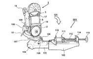
図1は本発明の実施例に係るバンドソー1の全体を示す正面図である。バンドソー1は、給電用の電源コードにより給電される交流電力によって駆動され、先端工具たる帯鋸8の走行により図示しない被切断材を切断するための電動工具である。給電がなされた状態で、作業者がトリガスイッチ12を操作すると、ハウジング6内に配置された図示しないモータが回転する。バンドソー1のハウジング6の一方側には、駆動鋸車(図示せず)を収容するための鋸車ベース4が設けられ、他方側には従動鋸車(図示せず)を収容するための鋸車ベース5が設けられる。鋸車ベース4、5は広義のハウジング(筐体)の一部を構成するものであって鋸車を軸支するためのフレームの役目を兼用し、鋸車ベース4、5とハウジング6は一体式に又は別体式に製造される。第一の鋸車たる駆動鋸車と第二の鋸車たる従動鋸車の間には環状の帯鋸8が架け渡され、開口部9において帯鋸8の一部が露出する。モータは、図示しない回転伝達機構によって駆動鋸車を回転させる。回転駆動される駆動鋸車は、その回転力を帯鋸8に伝達し、帯鋸8を周回移動させる。従動鋸車は、周回移動する帯鋸8によって駆動鋸車に対して従動的に回転する円形の滑車であり、それらの間に張架されるエンドレスの帯鋸(バンドソー)8を回転させることにより鉄パイプ等の被切断材(図示せず)を切断することができる。   FIG. 1 is a front view showing an entire band saw 1 according to an embodiment of the present invention. The band saw 1 is an electric tool that is driven by AC power fed by a power cord for feeding and that cuts a material to be cut (not shown) by running a band saw 8 as a tip tool. When the operator operates the trigger switch 12 in a state where power is supplied, a motor (not shown) disposed in the housing 6 rotates. A saw wheel base 4 for receiving a drive saw wheel (not shown) is provided on one side of the housing 6 of the band saw 1, and a saw for receiving a driven saw wheel (not shown) on the other side. A car base 5 is provided. The saw wheel bases 4 and 5 constitute a part of the housing (housing) in a broad sense and also serve as a frame for supporting the saw wheel. The saw wheel bases 4 and 5 and the housing 6 are integrated. Manufactured in a formula or separately. An annular band saw 8 is bridged between the drive saw wheel as the first saw wheel and the driven saw wheel as the second saw wheel, and a part of the band saw 8 is exposed at the opening 9. The motor rotates the drive saw wheel by a rotation transmission mechanism (not shown). The drive saw wheel that is driven to rotate transmits the rotational force to the band saw 8 and moves the band saw 8 around. The driven saw wheel is a circular pulley that rotates in a driven manner with respect to the drive saw wheel by a band saw 8 that moves around, and an endless band saw (band saw) 8 that is stretched between them is rotated to turn the iron pipe. A material to be cut (not shown) such as the like can be cut.

バンドソー1で被切断材を切断する際は、帯鋸8が回転方向11(正回転方向)に回転し、この回転によって被切断材料が回転方向11と同方向に押されるため、押される側(駆動鋸車が設けられる側)にガイドプレート10が設けられる。ガイドプレート10は、被切断材料の大きさ・形状あるいは、被切断材料(既設管等)等とのスペースに応じて設定された形状と大きさを有しており、回転方向11と平行な方向と直交する方向に移動調整可能に構成される。ここでは開口部9において帯鋸8の前後には、2つのガイドローラーを有する帯鋸ガイド7、17が設けられる。   When the material to be cut is cut by the band saw 1, the band saw 8 rotates in the rotation direction 11 (forward rotation direction), and the material to be cut is pushed in the same direction as the rotation direction 11 by this rotation. A guide plate 10 is provided on the side where the saw wheel is provided. The guide plate 10 has a shape and size set in accordance with the size and shape of the material to be cut or a space with the material to be cut (existing pipe or the like), and the direction parallel to the rotation direction 11. It can be moved and adjusted in a direction orthogonal to the direction. Here, band saw guides 7 and 17 having two guide rollers are provided in the opening 9 before and after the band saw 8.

鋸車ベース5には、従動鋸車の位置を調整することにより帯鋸8の取付け又は取り外したり、張り具合を調整するためのテンションレバー19が設けられる。鋸車ベース5の上側付近には電源をオン又はオフするためのメインスイッチ26が設けられる。ハウジング6の右側の一端部にはハンドル部13が設けられ、上方左側付近(他端部)には補助ハンドル16が設けられる。トリガスイッチ12の上側には、トリガスイッチ12を引いた状態(オン状態)でロックすることができるように、オンロックボタン14が設けられる。トリガスイッチ12の直上には、帯鋸8の周速設定用の速度調整手段が設けられる。速度調整手段は速度設定ダイヤル20を含んで構成され、作業者は速度設定ダイヤル20を回転させる事によってモータの回転速度を任意に調整できる。   The saw wheel base 5 is provided with a tension lever 19 for adjusting or adjusting the tension of the band saw 8 by adjusting the position of the driven saw wheel. Near the upper side of the saw wheel base 5, a main switch 26 for turning on / off the power is provided. A handle portion 13 is provided at one end portion on the right side of the housing 6, and an auxiliary handle 16 is provided near the upper left side (the other end portion). An on-lock button 14 is provided above the trigger switch 12 so that the trigger switch 12 can be locked in the pulled state (on state). A speed adjusting means for setting the peripheral speed of the band saw 8 is provided immediately above the trigger switch 12. The speed adjusting means includes a speed setting dial 20, and the operator can arbitrarily adjust the rotation speed of the motor by rotating the speed setting dial 20.

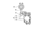
図2は本発明の実施例に係るバンドソー1を定置式スタンド101に取り付けた状態を示す正面図である。定置式スタンド101はベース102を有し、ベース102には切断すべき被切断材(図示せず)を固定するための固定手段(バイス装置)が装着される。バイス装置は、被切断材を支持する固定バイス110と可動バイス111が対向するように配置したものであり、可動バイス111を移動させるためのノブ113を有するネジ112を有する。ベース102に対するネジ112の固定は、クラッチ114を介して行われる。ベース102からは、車輪104付きの延長ベース103が延びるように設けられ、延長ベース103には、揺動軸105によってヒンジ107が軸支される。ヒンジ107の揺動軸105と同軸には、捻りバネ等のスプリング106が設けられる。ヒンジ107の揺動軸105とは離れた端部側にはバンドソー1を保持するための装着部108が設けられる。装着部108にバンドソー1を取り付けて、ネジ109にて固定することによりバンドソー1が定置式スタンド101に固定される。   FIG. 2 is a front view showing a state in which the band saw 1 according to the embodiment of the present invention is attached to the stationary stand 101. The stationary stand 101 has a base 102, and a fixing means (vise device) for fixing a material to be cut (not shown) to be cut is attached to the base 102. The vise device is arranged so that the fixed vise 110 and the movable vise 111 that support the material to be cut are opposed to each other, and has a screw 112 having a knob 113 for moving the movable vise 111. The screw 112 is fixed to the base 102 via the clutch 114. An extension base 103 with wheels 104 extends from the base 102, and a hinge 107 is pivotally supported on the extension base 103 by a swing shaft 105. A spring 106 such as a torsion spring is provided coaxially with the swing shaft 105 of the hinge 107. A mounting portion 108 for holding the band saw 1 is provided on the end portion side of the hinge 107 away from the swing shaft 105. The band saw 1 is fixed to the stationary stand 101 by attaching the band saw 1 to the mounting portion 108 and fixing with the screw 109.

作業者は、図示しない被切断材をベース102の上面に載せ、クラッチ114を動作させて可動バイス111を移動させて被切断材に突き当てる。次にノブ113を回転させて被切断材を固定する。次にバンドソー1を矢印120のように移動させて帯鋸8を被切断材に押し当て、トリガスイッチ12をオンにする。帯鋸8に衝撃が掛からないように、帯鋸8に加える荷重は、製品の自重のみとして、無理に荷重をかけないようにする。作業者は切り終わったらトリガスイッチ12をオフにする。この際に、製品の自重のみで切断ができるのでトリガスイッチ12のオンロック機構を用いると良い。オンロック手段はトリガスイッチ12の操作レバー12aを引いた状態(オン状態)を維持できるものであり、操作レバー12aを引いた状態で、オンロックボタン14を押すことによってオンロック手段が動作する(オンロック状態となる)。オンロック手段を解除(非動作状態)とするには、作業者が操作レバーを再度引くことで解除される。   The operator places a workpiece to be cut (not shown) on the upper surface of the base 102, operates the clutch 114, moves the movable vise 111, and hits the workpiece. Next, the knob 113 is rotated to fix the material to be cut. Next, the band saw 1 is moved as indicated by an arrow 120, the band saw 8 is pressed against the material to be cut, and the trigger switch 12 is turned on. The load applied to the band saw 8 is only the weight of the product so that the band saw 8 is not impacted. The operator turns off the trigger switch 12 when it has been turned off. At this time, since the product can be cut only by its own weight, an on-lock mechanism of the trigger switch 12 is preferably used. The on-lock means can maintain the state where the operation lever 12a of the trigger switch 12 is pulled (on state), and the on-lock means operates by pressing the on-lock button 14 while the operation lever 12a is pulled (see FIG. On-lock state). To release the on-lock means (non-operating state), the operator releases it by pulling the operation lever again.

次に図3を用いて速度設定ダイヤル20のダイヤル位置と帯鋸の周速38との関係を説明する。速度設定ダイヤル20は回転式であって、時計にたとえると8時の位置から4時の位置にまで回転させる事によって速度1〜5の範囲の任意の位置に設定することができる。例えば無負荷時において、速度1は50m/分(=最低速度Vmin)で速度5(=最高速度V2)では150m/分程度である。ここで、本実施例では周速が速度4未満の低速領域(第1の状態)まではオンロック機能の動作を許可し、速度4以上の高速領域(第2の状態)の場合はオンロック手段が動作しないように構成した。ここでは速度4、つまりオンロック手段を認めるか認めないかの閾値V1は、周速125m/分程度であるが、閾値V1をどの程度に設定するかは任意である。尚、モータの回転力は図示しない減速機構を介して駆動鋸車に伝達されるので、閾値V1を越えているかどうかはモータの回転数N1を越えたかどうかで判断できる。ここではモータの回転数N2の時に帯鋸の最高速度V2となる。速度設定ダイヤル20が速度4を越える場合は、作業者がトリガスイッチ12を引きながらオンロックボタン14を押そうとしても、物理的にオンロックボタン14が動かないように構成される。このようにオンロックボタン14の移動が不能なように機械的な構成にてオンロックボタン14の移動を阻止又は許容するようにした。 Next, the relationship between the dial position of the speed setting dial 20 and the peripheral speed 38 of the band saw will be described with reference to FIG. The speed setting dial 20 is a rotary type, and can be set to an arbitrary position in the range of speeds 1 to 5 by rotating from an 8 o'clock position to a 4 o'clock position, for example, in a watch. For example, at no load, the speed 1 is 50 m / min (= minimum speed V min ) and the speed 5 (= maximum speed V2) is about 150 m / min. Here, in the present embodiment, the operation of the on-lock function is permitted up to a low speed region (first state) where the peripheral speed is less than 4; The means was configured not to work. Here, the threshold value V1 for determining whether or not to recognize the speed 4, that is, the on-lock means is about 125 m / min., However, how much the threshold value V1 is set is arbitrary. Since the rotational force of the motor is transmitted to the drive saw wheel via a reduction mechanism (not shown), whether or not the threshold value V1 is exceeded can be determined by whether or not the rotational speed N1 of the motor is exceeded. Here, the maximum speed V2 of the band saw is obtained when the rotational speed of the motor is N2. When the speed setting dial 20 exceeds the speed 4, even if the operator tries to press the on-lock button 14 while pulling the trigger switch 12, the on-lock button 14 is not physically moved. In this way, the movement of the on-lock button 14 is prevented or permitted by a mechanical configuration so that the on-lock button 14 cannot be moved.

図4はバンドソー1の速度設定ダイヤル20とトリガスイッチ12の連結構成を示す正面図である。トリガスイッチ12は、スイッチ部12bと、操作レバー12aによって主に構成される。図4では操作レバー12aをスイッチ部12b側に一杯に引いた(移動させた)状態を示している。操作レバー12aには、オンロックボタン14の円柱状のボタン部14aから延びる細径のロックピン14b(後述する図5参照)が貫通するためのスリット状の長穴12cが形成される。長穴12cは、操作レバー12aの移動方向と平行に延びるスリット状であって、操作レバー12aを一杯に引いた状態でオンロックボタン14のボタン部14aを貫通させるための丸穴(図では見えない)が長穴12cの端部に形成される。このような構成によって、オンロック手段を動作させることができるが、ここではオンロックボタン14には上方に延びるアーム部15が形成される。オンロックボタン14とアーム部15は、合成樹脂の一体成形によって製造される。   FIG. 4 is a front view showing a connection configuration of the speed setting dial 20 and the trigger switch 12 of the band saw 1. The trigger switch 12 is mainly configured by a switch portion 12b and an operation lever 12a. FIG. 4 shows a state in which the operation lever 12a is fully pulled (moved) toward the switch portion 12b. The operation lever 12a is formed with a slit-like long hole 12c through which a thin lock pin 14b (see FIG. 5 described later) extending from the cylindrical button portion 14a of the on-lock button 14 passes. The elongated hole 12c has a slit shape extending in parallel with the moving direction of the operation lever 12a, and is a round hole (visible in the figure) for penetrating the button portion 14a of the on-lock button 14 with the operation lever 12a fully pulled. Is not formed at the end of the long hole 12c. With such a configuration, the on-lock means can be operated. Here, the on-lock button 14 is formed with an arm portion 15 that extends upward. The on-lock button 14 and the arm portion 15 are manufactured by integral molding of synthetic resin.

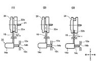
図5は速度設定ダイヤル20とトリガスイッチ12の動作状況を説明するための側面図である。速度設定ダイヤル20は回転軸21を中心として半回転以上一回転未満の回転が可能であり、軸方向の中央付近にはアーム部15の上側端部を案内するための溝部(22a、22b)が形成される。溝部22aは軸方向に広い幅を有し、溝部22bは軸方向に狭い幅を有する。特に狭い溝部22bはアーム部の前後方向幅とほぼ同等程度に構成される。図5(1)は、速度設定ダイヤル20が速度3付近にある状態を示しており、この位置では、アーム部15の上端が広い幅の溝部22a内にあるため、オンロックボタン14を矢印23の方向に移動させることができる。移動させた状態を示すのが(2)であり、この状態になるとオンロックボタン14のロックピン14bが操作レバー12aの長穴12cの丸穴の内部に位置することにより、操作レバー12aの移動が阻止される。この状態で作業者が操作レバー12aを戻すと、操作レバー12aがもとの位置に戻ろうとするために、切り欠き14cが長穴12cの縁部分に引っ掛かる状態となるため、操作レバー12aが係止状態となり、ロック状態が維持される。   FIG. 5 is a side view for explaining the operation state of the speed setting dial 20 and the trigger switch 12. The speed setting dial 20 can rotate more than half rotation and less than one rotation around the rotation shaft 21, and groove portions (22 a, 22 b) for guiding the upper end portion of the arm portion 15 are near the center in the axial direction. It is formed. The groove 22a has a wide width in the axial direction, and the groove 22b has a narrow width in the axial direction. In particular, the narrow groove portion 22b is configured to be approximately the same as the width in the front-rear direction of the arm portion. FIG. 5 (1) shows a state in which the speed setting dial 20 is in the vicinity of the speed 3. At this position, the upper end of the arm portion 15 is in the wide groove portion 22a, and therefore the on-lock button 14 is moved to the arrow 23. It can be moved in the direction. (2) shows the moved state. In this state, the lock pin 14b of the on-lock button 14 is located inside the round hole of the elongated hole 12c of the operation lever 12a, so that the operation lever 12a is moved. Is blocked. When the operator returns the operating lever 12a in this state, the operating lever 12a tries to return to the original position, so that the notch 14c is caught by the edge portion of the elongated hole 12c. The locked state is maintained.

図5(3)は、速度設定ダイヤル20が速度5付近にある状態を示しており、速度4〜5の位置にある場合は、アーム部15の先端が狭い幅の溝部22bに位置するため、アーム部15の矢印23の方向への移動阻止に伴いオンロックボタン14も後方(操作レバー12aに接近する方向)への移動ができないことになる。このように本実施例では速度設定ダイヤル20と、オンロックボタン14との機械的な接続構造を用いて、帯鋸の周速が所定の閾値よりも高速の時にはオンロック手段が阻止されてオンロックできないように構成し、帯鋸が所定の閾値よりも低速の時にはオンロック手段が作動するように構成した。   FIG. 5 (3) shows a state in which the speed setting dial 20 is in the vicinity of the speed 5, and when the speed setting dial 20 is in the position of the speed 4-5, the tip of the arm part 15 is located in the narrow groove part 22b. As the arm portion 15 is prevented from moving in the direction of the arrow 23, the on-lock button 14 cannot move backward (in the direction approaching the operation lever 12a). In this way, in this embodiment, the mechanical connection structure between the speed setting dial 20 and the on-lock button 14 is used, and the on-lock means is blocked and on-locked when the peripheral speed of the band saw is higher than a predetermined threshold. The on-lock means is configured to operate when the band saw is slower than a predetermined threshold.

第1の実施例においては、速度設定ダイヤル20とオンロックボタン14の構成を工夫することで機械的な構成により高速領域でのオンロック機能の阻止を実現した。第2の実施例では機械的な構成によってのオンロック機能の阻止ではなくて、電気的な構成により高速領域でのオンロック機能の阻止を実現したものである。図6はモータの駆動制御系の構成を示すブロック図である。本実施例では、モータ3は3相のブラシレスDCモータで構成される。モータ3は、いわゆるインナーロータ型で、二組のN極およびS極を含む永久磁石を埋め込んで構成されたロータ3bと、スター結線された3相巻線U、V、Wからなるステータ3aを含んで構成される。ロータ3bの回転位置は60°毎に配置された3つの位置検出素子28を用いて検出される。   In the first embodiment, the configuration of the speed setting dial 20 and the on-lock button 14 is devised to prevent the on-lock function in the high-speed region by a mechanical configuration. In the second embodiment, the on-lock function is not blocked by the mechanical configuration, but the on-lock function is blocked by the electrical configuration in the high-speed region. FIG. 6 is a block diagram showing the configuration of the motor drive control system. In the present embodiment, the motor 3 is constituted by a three-phase brushless DC motor. The motor 3 is of a so-called inner rotor type, and includes a rotor 3b configured by embedding permanent magnets including two sets of N poles and S poles, and a stator 3a composed of star-connected three-phase windings U, V, and W. Consists of including. The rotational position of the rotor 3b is detected using three position detecting elements 28 arranged every 60 °.

インバータ回路27は、3相ブリッジ形式に接続された6個のFET(以下、単に「トランジスタ」という。)Q1〜Q6から主に構成される。インバータ回路27への入力用電源として、本実施例では直流源29から供給される直流を用いる。本実施例では、電源コード18(図2参照)を用いて供給される商用電源(交流)を図示しない整流回路を用いて直流源29としても良いし、ニカド電池、リチウムイオン電池等の二次電池を直流源29としても良い。ブリッジ接続された6個のトランジスタQ1〜Q6の各ゲートは制御信号出力回路42に接続され、ソースまたはドレインはスター結線された電機子巻線U、VおよびWに接続される。これらの接続によって、6個のトランジスタQ1〜Q6は、制御信号出力回路42から出力された駆動信号によってスイッチング動作を行い、インバータ回路27に印加される直流を、電気角120°の電流の通電区間を有する3相(U相、V相、W相)交流Vu、Vv、Vwとして、電機子巻線U、V、Wへ供給する。   The inverter circuit 27 is mainly composed of six FETs (hereinafter simply referred to as “transistors”) Q1 to Q6 connected in a three-phase bridge form. In this embodiment, a direct current supplied from a direct current source 29 is used as an input power source for the inverter circuit 27. In the present embodiment, the commercial power supply (AC) supplied using the power cord 18 (see FIG. 2) may be used as the DC source 29 using a rectifier circuit (not shown), or a secondary such as a NiCad battery or a lithium ion battery. A battery may be used as the direct current source 29. The gates of the six transistors Q1 to Q6 that are bridge-connected are connected to the control signal output circuit 42, and the sources or drains are connected to the armature windings U, V, and W that are star-connected. With these connections, the six transistors Q1 to Q6 perform a switching operation according to the drive signal output from the control signal output circuit 42, and the direct current applied to the inverter circuit 27 is converted into a current conduction period of an electrical angle of 120 °. Are supplied to the armature windings U, V, W as three-phase (U-phase, V-phase, W-phase) AC Vu, Vv, Vw.

インバータ回路27の制御やモータ3のオンオフ及び回転速度制御は、演算部41を含んで構成される制御装置40によって制御される。演算部41は、処理プログラムとデータに基づいて駆動信号を出力するためのCPUと、後述するフローチャートに相当するプログラムや制御データを記憶するためのROMと、データを一時記憶するためのRAMと、タイマ等を含んで構成され、例えば市販のマイクロコンピュータを用いて実現される。位置検出素子28からの位置検出信号は、回転子位置検出回路43によってパルス信号として演算部41に入力される。モータ回転数検出回路44は回転子位置検出回路43の出力からモータ3の回転速度を検出して演算部41に出力する。   Control of the inverter circuit 27, on / off of the motor 3, and rotation speed control are controlled by a control device 40 including a calculation unit 41. The calculation unit 41 includes a CPU for outputting a drive signal based on a processing program and data, a ROM for storing a program and control data corresponding to a flowchart to be described later, a RAM for temporarily storing data, It includes a timer and the like, and is realized using, for example, a commercially available microcomputer. The position detection signal from the position detection element 28 is input to the calculation unit 41 as a pulse signal by the rotor position detection circuit 43. The motor rotation number detection circuit 44 detects the rotation speed of the motor 3 from the output of the rotor position detection circuit 43 and outputs it to the calculation unit 41.

モータ電流検出手段は、シャント抵抗46とシャント抵抗46の両端電圧を測定することによりモータ電流値を検出するモータ電流検出回路45により構成され、モータ電流検出回路45の出力は演算部41に入力される。電圧検出回路49は直流源29の電圧を測定して演算部41に出力する。演算部41のA/D変換器にはトリガスイッチ12の出力と、速度切替スイッチ58の設定状態を検出する回転速度設定回路48の出力と、オンロックスイッチ59の出力が入力される。速度表示LED57は、複数のLEDを有する速度設定レベルを示す表示装置(後述)であり、演算部41は、回転速度設定回路48によって指示される回転速度レベルに対応して所定の数のLED(図6にて後述するLED57)を点灯させる。   The motor current detection means includes a shunt resistor 46 and a motor current detection circuit 45 that detects the motor current value by measuring the voltage across the shunt resistor 46, and the output of the motor current detection circuit 45 is input to the calculation unit 41. The The voltage detection circuit 49 measures the voltage of the DC source 29 and outputs it to the calculation unit 41. The output of the trigger switch 12, the output of the rotational speed setting circuit 48 that detects the setting state of the speed changeover switch 58, and the output of the on-lock switch 59 are input to the A / D converter of the calculation unit 41. The speed display LED 57 is a display device (described later) showing a speed setting level having a plurality of LEDs, and the calculation unit 41 has a predetermined number of LEDs (corresponding to the rotational speed level indicated by the rotational speed setting circuit 48). The LED 57) described later with reference to FIG. 6 is turned on.

ここでトリガスイッチ12は、操作レバー12aの移動ストロークに応答してオン又はオフのいずれかの状態に切り替わる切り替えスイッチであり、High信号又はLow信号(又はゼロ信号)が演算部41に入力される。第二の実施例では、トリガスイッチ12の動作状況としてオンロックスイッチ59による電子的なオンロックを有効にするモードと、電子的なオンロックを無効とするモードの2つの動作モードを有する。図7はその操作パネル56を示す図である。   Here, the trigger switch 12 is a changeover switch that switches to either an on state or an off state in response to the movement stroke of the operation lever 12 a, and a high signal or a low signal (or zero signal) is input to the calculation unit 41. . In the second embodiment, the operation state of the trigger switch 12 has two operation modes: a mode for enabling electronic on-lock by the on-lock switch 59 and a mode for disabling electronic on-lock. FIG. 7 is a diagram showing the operation panel 56.

図7の操作パネル56は図1において速度設定ダイヤル20を設ける代わりにバンドソー1の任意の場所に設けることができる。バンドソー1にはモータ3の回転速度を、遅、中、速の3段階に設定するための速度切替スイッチ58と、速度切替スイッチ58によって設定された速度を表示するための3つのセグメント化された点灯部を有する速度表示LED57を有して構成される。速度表示LED57は、速度が“遅”の時は左側の小さいLEDだけが点灯し、速度が“中”の時は左側と真ん中のLEDの2つが点灯し、速度が“速”の時はすべてのLEDが点灯する。オンロックスイッチ59は、電子的なオンロックを有効にするためのスイッチであり、オンロックを有効にするとソフトウェア制御によるオンロック手段が実現され、オンロックを有効にすると通常のトリガスイッチを用いたモータ3のオン又はオフ制御が実現される。ここでは、オンロック手段は、速度切替スイッチ58と制御装置40を含む速度調整手段によって選択されるモータ3の回転速度が、“遅”又は“中”の時(第1の状態)のみ動作するようにして、“速”の場合(第2の状態)は動作しないように設定した。あるいは、モータ3の回転速度が“速”のままでオンロックスイッチ59を押した場合は、自動的に演算部41がモータ3の回転速度を“中”に落とすように構成しても良い。   The operation panel 56 of FIG. 7 can be provided at an arbitrary place of the band saw 1 instead of providing the speed setting dial 20 in FIG. The band saw 1 is divided into three segments for displaying the speed set by the speed changeover switch 58 and the speed changeover switch 58 for setting the rotation speed of the motor 3 in three stages of slow, medium and high speed. A speed display LED 57 having a lighting part is included. When the speed is “slow”, only the small LED on the left side is lit. When the speed is “medium”, the left LED and the middle LED are lit. LED lights up. The on-lock switch 59 is a switch for enabling electronic on-lock. When the on-lock is enabled, software-controlled on-lock means is realized, and when on-lock is enabled, a normal trigger switch is used. On / off control of the motor 3 is realized. Here, the on-lock means operates only when the rotation speed of the motor 3 selected by the speed adjustment means including the speed changeover switch 58 and the control device 40 is “slow” or “medium” (first state). In this way, it was set so as not to operate in the case of “speed” (second state). Alternatively, when the on-lock switch 59 is pressed while the rotation speed of the motor 3 is “fast”, the calculation unit 41 may automatically reduce the rotation speed of the motor 3 to “medium”.

操作パネル56においては、速度切替スイッチ58、オンロックスイッチ59の他に、帯鋸8の切断領域付近を照射する図示しないLEDランプの点灯スイッチ60が設けられる。これらのスイッチは例えばタクタイルスイッチなどのライトタッチスイッチを、表面に印刷が施された可撓性のシートで覆うことで構成できる。尚、オンロックスイッチ59がオンになっているかどうかを視認できるようにLEDを別途設けるようにしても良い。   In addition to the speed change switch 58 and the on-lock switch 59, the operation panel 56 is provided with an LED lamp lighting switch 60 (not shown) that irradiates the vicinity of the cutting area of the band saw 8. These switches can be configured by covering a light touch switch such as a tactile switch with a flexible sheet printed on the surface. In addition, you may make it provide LED separately so that it can visually recognize whether the on-lock switch 59 is set to ON.

図8は、本発明の第二の実施例におけるトリガスイッチ12と帯鋸8の周速との関係を示す図であって、オンロック手段非動作時(オンロックスイッチ59がオフ)の動作を示す図である。図8において(1)(2)共に横軸は時間であり、時間軸を合わせて図示している。(1)の縦軸はトリガスイッチのオンオフ状態51を示し、(2)の縦軸は帯鋸8の周速52を示している。ここでは帯鋸8の周速(m/分)がV1とV2の2段階しか示していないが、第二の実施例では三段階の設定ができるので、V1以下の周速(例えばV0)の設定も可能である。ここでは時刻tにて作業者がトリガスイッチ12を引いてオンにすることによりモータ3が回転して、時刻tにてトリガスイッチ12を離すことによりモータ3の回転が停止する状態を示している。ここでは、モータ3の回転速度が、“高”の設定であるので、帯鋸8の周速は最高速たるV2で回転し、この際のモータの回転数はN2である。 FIG. 8 is a diagram showing the relationship between the trigger switch 12 and the peripheral speed of the band saw 8 in the second embodiment of the present invention, and shows the operation when the on-lock means is not in operation (the on-lock switch 59 is off). FIG. In FIGS. 8A and 8B, the horizontal axis is time in both (1) and (2), and the time axis is shown together. The vertical axis of (1) indicates the on / off state 51 of the trigger switch, and the vertical axis of (2) indicates the peripheral speed 52 of the band saw 8. Here, the peripheral speed (m / min) of the band saw 8 shows only two steps of V1 and V2. However, since the second embodiment can be set in three steps, the peripheral speed (for example, V0) below V1 can be set. Is also possible. Here rotates the motor 3 by an operator at time t 1 is turned on pulling the trigger switch 12 indicates a state where the rotation of the motor 3 is stopped by releasing the trigger switch 12 at time t 2 ing. Here, since the rotational speed of the motor 3 is set to “high”, the peripheral speed of the band saw 8 rotates at the maximum speed V2, and the rotational speed of the motor at this time is N2.

図9は、本発明の第二の実施例におけるトリガスイッチ12と帯鋸8の周速との関係を示す図であって、オンロック手段の動作時の状態を示す図である。図9において(1)(2)共に横軸は時間であり、時間軸を合わせて図示している。(1)の縦軸はトリガスイッチのオンオフ状態53を示し、(2)の縦軸は帯鋸8の周速54を示している。ここではモータ3の回転速度が“中”の設定を示している。オンロック手段の動作時には、作業者は時刻tにてトリガスイッチ12を短い時間引くことでモータ3の回転が開始して、帯鋸8の周速がV1(トリガロック手段が動作可能な時の最高回転数)に保たれ、この際のモータの回転数はN1である。時刻tにて作業者が再びトリガスイッチ12を短い時間引くことでモータ3の回転が停止する。このようにマイコンを有する演算部41を用いてトリガスイッチ12のオン状態を維持するようにしたオンロック手段を電気的に実現することができる。さらに、オンロック手段は所定の速度以下の時には作動するが、所定の速度(周速V1、又は、モータの回転数N1)を超える場合にはオンロック手段が作動しないように制御装置40が制御するので、安定して精度の高い切断作業を行うことができる。 FIG. 9 is a diagram showing the relationship between the trigger switch 12 and the peripheral speed of the band saw 8 in the second embodiment of the present invention, and is a diagram showing a state during operation of the on-lock means. In FIGS. 9A and 9B, the horizontal axis is time in both (1) and (2), and the time axis is shown together. The vertical axis of (1) indicates the on / off state 53 of the trigger switch, and the vertical axis of (2) indicates the peripheral speed 54 of the band saw 8. Here, the rotation speed of the motor 3 is set to “medium”. During the operation of the on-lock means, the operator pulls the trigger switch 12 at a time t 1 for a short time to start the rotation of the motor 3, and the peripheral speed of the band saw 8 becomes V 1 (when the trigger lock means is operable). The maximum number of revolutions) is maintained, and the number of revolutions of the motor at this time is N1. Operator at time t 2 is the rotation of the motor 3 is stopped by pulling a short time the trigger switch 12 again. Thus, the on-lock means which maintains the ON state of the trigger switch 12 using the calculating part 41 which has a microcomputer can be electrically implement | achieved. Further, the on-lock means operates when the speed is lower than the predetermined speed, but the control device 40 controls the on-lock means not to operate when the predetermined speed (peripheral speed V1 or motor rotation speed N1) is exceeded. Therefore, a stable and highly accurate cutting operation can be performed.

次に図10〜図13を用いて本発明の第三の実施例について説明する。第三の実施例では機械的な構成でモータのオンロック手段を設けたものであるが、速度調整手段が第1の状態(“高速”)と第2の状態(“低速”)とを選択可能なこと、速度が“低速”の時だけオンロック手段が機能するように構成したものである。図10は本発明の第三の実施例におけるバンドソー61の全体を示す斜視図である。基本的な構成は第一の実施例で説明したバンドソー1とほぼ同じであり、同じ構成要素には同じ番号の参照符号を付している。   Next, a third embodiment of the present invention will be described with reference to FIGS. In the third embodiment, the motor on-lock means is provided with a mechanical configuration, but the speed adjustment means selects the first state (“high speed”) and the second state (“low speed”). What is possible is that the on-lock means functions only when the speed is "low speed". FIG. 10 is a perspective view showing the whole of the band saw 61 in the third embodiment of the present invention. The basic configuration is almost the same as that of the band saw 1 described in the first embodiment, and the same constituent elements are denoted by the same reference numerals.

ハンドル部63にはトリガスイッチ62が設けられる。速度切替レバー67と、トリガスイッチ62の操作レバーは、一つのスイッチユニットによって構成される。トリガスイッチ62には、オンロックボタン64が設けられ、その上方にはモータの回転速度を“高”又は”低速”に切替えるための速度切替レバー67(速度調整手段)が設けられる。ここでは、モータの回転速度を”低速”に設定した場合には、オンロックボタン64の操作が可能であり、モータの回転速度を“高”に設定した場合には、オンロックボタン64の操作が不能、つまり、操作できない(オンロックボタン64を押すことができない)ように構成した。   The handle portion 63 is provided with a trigger switch 62. The speed switching lever 67 and the operation lever of the trigger switch 62 are constituted by one switch unit. The trigger switch 62 is provided with an on-lock button 64, and a speed switching lever 67 (speed adjusting means) for switching the rotational speed of the motor to “high” or “low speed” is provided above it. Here, when the motor rotation speed is set to “low speed”, the on-lock button 64 can be operated, and when the motor rotation speed is set to “high”, the on-lock button 64 is operated. Is impossible, that is, cannot be operated (the on-lock button 64 cannot be pressed).

図11はトリガスイッチ62と速度切替レバー67の上面図である。(1)は速度切替レバー67を取り付けた状態の上面図であり、(2)は速度切替レバー67を取り外した状態の上面図である。トリガスイッチ62は、スイッチ部62bと、操作レバー62aと、速度切替え用の速度切替アーム62cによって構成される。操作レバー62aを図中に示す矢印71の方向に移動可能であり、図では操作レバー62aが引かれていない位置(OFFの位置)を示している。スイッチ部62bの上部であって、操作レバー62aの上側には、スイッチ部62bから速度切替アーム62cが前方に延びるように設けられる。(2)からわかるように速度切替アーム62cの一方はスイッチ部62b側に軸支され、その反対側の端部に円柱形の係合部62dが設けられる。係合部62dは速度切替レバー67から前方側に突出する部分に形成された長穴部67aに配置されることにより、速度切替レバー67を矢印72に示す移動方向のいずれかに移動させることにより、速度切替アーム62cが一方側又は他方側に移動する。図11(1)の状態は、速度切替レバー67が中立の位置(一方側と他方側の中間の位置)にあって、この位置では係合部62dが操作レバー62aの中央に形成された凸部62gに当接するので、操作レバー62aを引くことができない(オフロック機構)。速度切替レバー67を一方側又は他方側に移動させることにより、係合部62dが凸部62gの両脇の溝部の内部に入り込むので操作レバー62aのオフロック機構が解除され、操作レバー62aを引くことができるようになる。   FIG. 11 is a top view of the trigger switch 62 and the speed switching lever 67. (1) is a top view with the speed switching lever 67 attached, and (2) is a top view with the speed switching lever 67 removed. The trigger switch 62 includes a switch portion 62b, an operation lever 62a, and a speed switching arm 62c for speed switching. The operation lever 62a can be moved in the direction of the arrow 71 shown in the drawing, and the drawing shows a position where the operation lever 62a is not pulled (OFF position). A speed switching arm 62c is provided on the upper portion of the switch portion 62b and above the operation lever 62a so as to extend forward from the switch portion 62b. As can be seen from (2), one of the speed switching arms 62c is pivotally supported on the switch part 62b side, and a cylindrical engaging part 62d is provided on the opposite end. The engaging portion 62d is disposed in a long hole portion 67a formed in a portion protruding forward from the speed switching lever 67, thereby moving the speed switching lever 67 in one of the moving directions indicated by the arrow 72. The speed switching arm 62c moves to one side or the other side. In the state of FIG. 11 (1), the speed switching lever 67 is in a neutral position (an intermediate position between one side and the other side), and at this position, the engaging portion 62d is formed at the center of the operation lever 62a. Since it contacts the part 62g, the operation lever 62a cannot be pulled (off-lock mechanism). By moving the speed switching lever 67 to one side or the other side, the engaging portion 62d enters into the grooves on both sides of the convex portion 62g, so the off-lock mechanism of the operating lever 62a is released and the operating lever 62a is pulled. Will be able to.

図12はトリガスイッチ62とオンロックボタン64の動作状況を説明するための上面図である。オンロックボタン64は操作レバー62aの移動方向(矢印71)と直交する方向に軸方向が位置する略円柱形の部材である。図12(1)は、速度切替レバー67によってモータの速度として“高速”が選択されている状態を示す。この状態ではオンロックボタン64のロックピン64b(図13にて詳述)が円柱形の係合部62dに当接するために、矢印73a方向への移動ができないのでオンロック機能が阻止される。一方、図12(2)は、速度切替レバー67によってモータの速度が低速側である”低速”が選択されている状態を示す。この状態ではオンロックボタン64のロックピン64b(図13にて詳述)が係合部62dに当接しないため矢印73a方向への移動が許容され、操作レバー62aに形成されるロック穴62fに入り込むのでオンロック状態が維持可能になる。   FIG. 12 is a top view for explaining the operation state of the trigger switch 62 and the on-lock button 64. The on-lock button 64 is a substantially cylindrical member whose axial direction is located in a direction orthogonal to the moving direction (arrow 71) of the operation lever 62a. FIG. 12 (1) shows a state in which “high speed” is selected as the motor speed by the speed switching lever 67. In this state, since the lock pin 64b (detailed in FIG. 13) of the on-lock button 64 abuts on the cylindrical engaging portion 62d, the on-lock function is prevented because the lock pin 64b cannot move in the direction of the arrow 73a. On the other hand, FIG. 12B shows a state in which “low speed” in which the speed of the motor is on the low speed side is selected by the speed switching lever 67. In this state, the lock pin 64b (detailed in FIG. 13) of the on-lock button 64 does not come into contact with the engaging portion 62d, so that movement in the direction of the arrow 73a is allowed, and the lock hole 62f formed in the operation lever 62a is allowed. Since it enters, the on-lock state can be maintained.

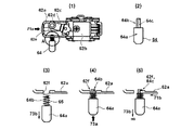
次に図13を用いてオンロックボタン64の動作状況をさらに説明する。(1)は、トリガスイッチ62の上面図であり、操作レバー62aが矢印71aの方向に移動した後の状態(トリガONの状態)であって、さらにオンロックボタン64によってオンロック状態が維持されている状態である。速度切替アーム62cのオンロックボタン64側には突起部62eが設けられる。(1)のモータの速度として“高速”が選択されている状態では、突起部62eがオンロックボタン64のロックピン64bの先端と当接する。(2)はオンロックボタン64の上面図であり、太径の略円柱形の本体部64aに細径の略円柱状のロックピン64bが接続される。ロックピン64bの軸心から見て径方向の一方向側、ここではスイッチ部62bが位置する側には、ロックピン64bをロック位置にて維持させるための切り欠き64cが形成される。   Next, the operation state of the on-lock button 64 will be further described with reference to FIG. (1) is a top view of the trigger switch 62, which is a state after the operation lever 62a has moved in the direction of the arrow 71a (trigger ON state), and the on-lock button 64 maintains the on-lock state. It is in a state. A protrusion 62e is provided on the on-lock button 64 side of the speed switching arm 62c. In a state where “high speed” is selected as the motor speed in (1), the protrusion 62 e comes into contact with the tip of the lock pin 64 b of the on-lock button 64. (2) is a top view of the on-lock button 64, in which a substantially cylindrical lock pin 64b having a small diameter is connected to a main body 64a having a large diameter. A notch 64c for maintaining the lock pin 64b in the locked position is formed on one side in the radial direction when viewed from the axis of the lock pin 64b, here, on the side where the switch portion 62b is located.

図13(3)は、操作レバー62aが引かれたトリガONの状態であり、操作レバー62aに形成された円形のロック穴62fがロックピン64bの同軸上に並んだ状態である。オンロックボタン64はコイルバネ65に作用によって矢印73bの方に付勢される。オンロックボタン64はハンドル部63の壁部によって矢印73bの方向に抜け落ちないように保持されるが、ここではその構造の記載は省略している。(3)の状態から作業者が指で矢印73aの方向にオンロックボタン64を押し込むことによって、操作レバー62aのロック穴62fにロックピン64bの先端が入り込むので、作業者が操作レバー62aを離したとしてもその状態が維持される(オンロック状態)。つまり、(3)の状態から作業者が操作レバー62aを離すと、操作レバー62aが図示しないバネの作用により矢印71bの方向に移動するが、その際、オンロックボタン64の切り欠き64cが操作レバー62aのロック穴62fの縁部に掛かるためにオンロックボタン64が矢印73bのように元の位置に復帰することが阻止される。   FIG. 13 (3) shows a state in which the trigger is turned on when the operation lever 62a is pulled, and a state in which circular lock holes 62f formed in the operation lever 62a are arranged on the same axis as the lock pin 64b. The on-lock button 64 is biased toward the arrow 73b by the action of the coil spring 65. The on-lock button 64 is held by the wall portion of the handle portion 63 so as not to fall off in the direction of the arrow 73b, but the description of its structure is omitted here. When the operator pushes the on-lock button 64 with the finger in the direction of the arrow 73a from the state of (3), the tip of the lock pin 64b enters the lock hole 62f of the operation lever 62a, so that the operator releases the operation lever 62a. Even if it does, the state is maintained (on-lock state). That is, when the operator releases the operation lever 62a from the state (3), the operation lever 62a moves in the direction of the arrow 71b due to the action of a spring (not shown). At this time, the notch 64c of the on-lock button 64 is operated. The on-lock button 64 is prevented from returning to the original position as shown by the arrow 73b because it is engaged with the edge of the lock hole 62f of the lever 62a.

以上説明したように、第三の実施例ではモータの速度のさらなる高速化を図りつつも、トリガスイッチのオンロック手段を設けたいという双方の要求を満たすことができた。特に、オンロック手段を動作させる際には帯鋸をある速度以下の場合のみに制限したので、手ぶれのし易い高速域ではオンロック手段を動作させずに、低速域でのみオンロック手段を動作させることができるバンドソーを実現できた。   As described above, in the third embodiment, it was possible to satisfy both demands for providing an on-lock means for the trigger switch while further increasing the speed of the motor. In particular, when operating the on-lock means, the band saw is limited only to a certain speed or less, so the on-lock means is operated only in the low speed range without operating the on-lock means in the high speed range where camera shake is likely to occur. A band saw that can be used.

以上、本発明を実施例に基づいて説明したが、本発明は上述の実施例に限定されるものではなく、その趣旨を逸脱しない範囲内で種々の変更が可能である。例えば、上述のじっしれでは電動工具の一例としてバンドソーを用いて説明したが、バンドソーだけに限られずに速度調整手段又は速度切替え手段付きの電動工具であれば本発明を同様に適用できる。   As mentioned above, although this invention was demonstrated based on the Example, this invention is not limited to the above-mentioned Example, A various change is possible within the range which does not deviate from the meaning. For example, in the above-described case, the band saw is used as an example of the electric tool. However, the present invention can be similarly applied to any electric tool with speed adjusting means or speed switching means without being limited to the band saw.

1 バンドソー 3 モータ
3a ステータ 3b ロータ
4 鋸車ベース 5 鋸車ベース
6 ハウジング 7 帯鋸ガイド
8 帯鋸 9 開口部
10 ガイドプレート 11 回転方向
12 トリガスイッチ 12a 操作レバー
12b スイッチ部 12c 長穴
13 ハンドル部 14 オンロックボタン
14a ボタン部 14b ロックピン
14c 切り欠き 15 アーム部
16 補助ハンドル 17 帯鋸ガイド
18 電源コード 19 テンションレバー
20 速度設定ダイヤル 21 回転軸
22a、22b 溝部 26 メインスイッチ
27 インバータ回路 28 位置検出素子
29 直流源 38 周速
40 制御装置(制御手段) 41 演算部
42 制御信号出力回路 43 回転子位置検出回路
44 モータ回転数検出回路 45 モータ電流検出回路
46 シャント抵抗 48 回転速度設定回路
49 電圧検出回路 51 オンオフ状態
52 周速 53 オンオフ状態
54 周速 56 操作パネル
57 速度表示LED 58 速度切替スイッチ
59 オンロックスイッチ 60 点灯スイッチ
61 バンドソー 62 トリガスイッチ
62a 操作レバー 62b スイッチ部
62c 速度切替アーム 62d 係合部
62e 突起部 62f ロック穴
62g 凸部 63 ハンドル部
64 オンロックボタン 64a 本体部
64b ロックピン 64c 切り欠き
65 コイルバネ 67 速度切替レバー
67a 長穴部 101 定置式スタンド
102 ベース 103 延長ベース
104 車輪 105 揺動軸
106 スプリング 107 ヒンジ
108 装着部 109 ネジ
110 固定バイス 111 可動バイス
112 ネジ 113 ノブ
114 クラッチ Q1〜Q6 FET
DESCRIPTION OF SYMBOLS 1 Band saw 3 Motor 3a Stator 3b Rotor 4 Saw wheel base 5 Saw wheel base 6 Housing 7 Band saw guide 8 Band saw 9 Opening part 10 Guide plate 11 Rotation direction 12 Trigger switch 12a Operation lever 12b Switch part 12c Slot 13 Handle part 14 On-lock Button 14a Button part 14b Lock pin 14c Notch 15 Arm part 16 Auxiliary handle 17 Band saw guide 18 Power cord 19 Tension lever 20 Speed setting dial 21 Rotating shaft 22a, 22b Groove part 26 Main switch 27 Inverter circuit 28 Position detection element 29 DC source 38 Peripheral speed 40 Control device (control means) 41 Calculation unit 42 Control signal output circuit 43 Rotor position detection circuit 44 Motor rotation speed detection circuit 45 Motor current detection circuit 46 Shunt resistance 48 Rotation speed setting circuit 9 Voltage detection circuit 51 On-off state 52 Peripheral speed 53 On-off state 54 Peripheral speed 56 Operation panel 57 Speed display LED 58 Speed switch 59 On-lock switch 60 Lighting switch 61 Band saw 62 Trigger switch 62a Operation lever 62b Switch part 62c Speed switch arm 62d Engaging portion 62e Protruding portion 62f Lock hole 62g Protruding portion 63 Handle portion 64 On lock button 64a Main body portion 64b Lock pin 64c Notch 65 Coil spring 67 Speed switching lever 67a Long hole portion 101 Stationary stand 102 Base 103 Extension base 104 Wheel 105 Oscillating shaft 106 Spring 107 Hinge 108 Mounting part 109 Screw 110 Fixed vise 111 Movable vise 112 Screw 113 Knob 114 Clutch Q1-Q6 FET

Claims (6)

先端工具を駆動するモータと、
前記モータのオン又はオフの切替え行うトリガスイッチを有する電動工具において、
前記モータのオン状態を維持可能なオンロック手段を設け、
前記オンロック手段の非動作時のモータの最高回転数N2と、前記オンロック手段の動作時のモータの最高回転数N1が異なるようにしたことを特徴とする電動工具。
A motor that drives the tip tool;
In the electric tool having a trigger switch for switching on or off the motor,
Providing an on-lock means capable of maintaining the on-state of the motor;
The electric power tool characterized in that the maximum rotational speed N2 of the motor when the on-lock means is not operated differs from the maximum rotational speed N1 of the motor when the on-lock means is operated.
前記モータの回転速度を調整する速度調整手段を設け、
前記速度調整手段の設定速度が、前記N1より高い場合は、前記オンロック手段の動作が阻止されることを特徴とする請求項1に記載の電動工具。
Providing a speed adjusting means for adjusting the rotational speed of the motor;
The electric tool according to claim 1, wherein when the set speed of the speed adjusting means is higher than the N1, the operation of the on-lock means is blocked.
前記速度調整手段は第1の状態と第2の状態とを選択可能であり、
前記第1の状態では設定速度をN1以下に調整すると共に、前記オンロック手段の動作を許容し、
前記第2の状態では前記オンロック手段の動作が阻止されることを特徴とする請求項2に記載の電動工具。
The speed adjusting means can select a first state and a second state,
In the first state, the set speed is adjusted to N1 or less, and the operation of the on-lock means is allowed,
The power tool according to claim 2, wherein the operation of the on-lock means is blocked in the second state.
前記オンロック手段は、前記トリガスイッチの操作レバーと係合し、前記操作レバーをオン状態に固定するロックピンを有し、
前記速度調整手段は、前記第1の状態で前記ロックピンと前記操作レバーの係合を許容し、前記第2の状態で前記ロックピンと前記操作レバーの係合を阻止することを特徴とする請求項3に記載の電動工具。
The on-lock means includes a lock pin that engages with an operation lever of the trigger switch and fixes the operation lever in an on state;
The speed adjusting means allows the lock pin and the operation lever to be engaged in the first state, and prevents the lock pin and the operation lever from being engaged in the second state. 3. The electric tool according to 3.
第1の状態と第2の状態とを選択可能な速度調整手段と、
前記速度調整手段が前記第1の状態のとき前記モータの回転数をN1以下になるよう制御し、前記第2の状態のとき前記モータの回転数をN1より高い回転数で回転するよう制御する制御手段と、有し、
前記制御手段は、前記オンロック手段の動作時においては、前記速度調整手段の状態に係らず、前記モータをN1以下の回転数で回転させることを特徴とする請求項1に記載の電動工具。
Speed adjusting means capable of selecting a first state and a second state;
When the speed adjusting means is in the first state, the rotational speed of the motor is controlled to be N1 or less, and when the speed adjusting means is in the second state, the rotational speed of the motor is controlled to rotate at a rotational speed higher than N1. Control means, and
2. The electric tool according to claim 1, wherein the control unit rotates the motor at a rotation speed of N <b> 1 or less regardless of a state of the speed adjustment unit during operation of the on-lock unit.
環状の帯鋸が架け渡される第一鋸車及び第二鋸車と、
前記第一鋸車を回転させる前記モータと、
前記モータのオン又はオフの切替え行う前記トリガスイッチと、
前記オンロック手段と、
前記第一鋸車、前記第二鋸車及び前記モータを支持するハウジングを有し、
前記ハウジングには、前記第一鋸車と前記第二鋸車との間で前記帯鋸を露出させる開口部が形成され、前記開口部に位置する前記帯鋸で切断作業を行うことを特徴とする請求項2から5のいずれか一項に記載の電動工具。
A first saw wheel and a second saw wheel over which an annular band saw is bridged;
The motor for rotating the first saw wheel;
The trigger switch for switching on or off the motor; and
The on-lock means;
A housing for supporting the first saw wheel, the second saw wheel and the motor;
An opening for exposing the band saw is formed between the first saw wheel and the second saw wheel in the housing, and a cutting operation is performed with the band saw located in the opening. Item 6. The electric tool according to any one of Items 2 to 5.
JP2014242612A 2014-11-28 2014-11-28 Power tool Pending JP2016101646A (en)

Priority Applications (1)

Application Number Priority Date Filing Date Title
JP2014242612A JP2016101646A (en) 2014-11-28 2014-11-28 Power tool

Applications Claiming Priority (1)

Application Number Priority Date Filing Date Title
JP2014242612A JP2016101646A (en) 2014-11-28 2014-11-28 Power tool

Publications (1)

Publication Number Publication Date
JP2016101646A true JP2016101646A (en) 2016-06-02

Family

ID=56088120

Family Applications (1)

Application Number Title Priority Date Filing Date
JP2014242612A Pending JP2016101646A (en) 2014-11-28 2014-11-28 Power tool

Country Status (1)

Country Link
JP (1) JP2016101646A (en)

Cited By (2)

* Cited by examiner, † Cited by third party
Publication number Priority date Publication date Assignee Title
JP2019111641A (en) * 2017-12-22 2019-07-11 ディーフォン エレクテック カンパニー リミテッドDefond Electech Co., Ltd Locking system for use with trigger assembly of electrical device
JP2019534796A (en) * 2016-10-27 2019-12-05 ヒルティ アクチエンゲゼルシャフト Switch device for electric tools

Cited By (3)

* Cited by examiner, † Cited by third party
Publication number Priority date Publication date Assignee Title
JP2019534796A (en) * 2016-10-27 2019-12-05 ヒルティ アクチエンゲゼルシャフト Switch device for electric tools
US11189437B2 (en) 2016-10-27 2021-11-30 Hilti Aktiengesellschaft Switch device for a power tool
JP2019111641A (en) * 2017-12-22 2019-07-11 ディーフォン エレクテック カンパニー リミテッドDefond Electech Co., Ltd Locking system for use with trigger assembly of electrical device

Similar Documents

Publication Publication Date Title
US10549396B2 (en) Electric power tool
US10099303B2 (en) Electric power tool
JP7062400B2 (en) Impact driver
JP6380933B2 (en) Electric tool
JP6755152B2 (en) Electric work machine
JP5353516B2 (en) Portable tools
JP2017019224A (en) Chainsaw
US20210078146A1 (en) Electric work machine
US10491148B2 (en) Electric working machine
JP2016101646A (en) Power tool
JP2012011504A (en) Power tool
CN114269517A (en) Mode selection for power tools
JP2016140939A (en) Band saw
JP2009160744A (en) Table saw
JP5709087B2 (en) Electric tool
JP2019042850A (en) adapter
JP6489346B2 (en) Electric tool
JP2015080896A (en) Electric power tool
JP2012011497A (en) Portable cutting machine
JP2020131333A (en) Electric work machine
JP2016087716A (en) Cutting tool
US20210370544A1 (en) Electric work machine
JP2010194665A (en) Power tool switch
JP2015047646A (en) Electric power tool
JP2015009289A (en) Electric tool

Legal Events

Date Code Title Description
RD02 Notification of acceptance of power of attorney

Free format text: JAPANESE INTERMEDIATE CODE: A7422

Effective date: 20160331