JP2016100746A - Image processing device - Google Patents
Image processing device Download PDFInfo
- Publication number
- JP2016100746A JP2016100746A JP2014236415A JP2014236415A JP2016100746A JP 2016100746 A JP2016100746 A JP 2016100746A JP 2014236415 A JP2014236415 A JP 2014236415A JP 2014236415 A JP2014236415 A JP 2014236415A JP 2016100746 A JP2016100746 A JP 2016100746A
- Authority
- JP
- Japan
- Prior art keywords
- unit
- communication unit
- image processing
- mode
- power supply
- Prior art date
- Legal status (The legal status is an assumption and is not a legal conclusion. Google has not performed a legal analysis and makes no representation as to the accuracy of the status listed.)
- Granted
Links
Images

Classifications
-
- H—ELECTRICITY
- H04—ELECTRIC COMMUNICATION TECHNIQUE
- H04N—PICTORIAL COMMUNICATION, e.g. TELEVISION
- H04N1/00—Scanning, transmission or reproduction of documents or the like, e.g. facsimile transmission; Details thereof
- H04N1/00885—Power supply means, e.g. arrangements for the control of power supply to the apparatus or components thereof
- H04N1/00888—Control thereof
- H04N1/00896—Control thereof using a low-power mode, e.g. standby
-
- H—ELECTRICITY
- H04—ELECTRIC COMMUNICATION TECHNIQUE
- H04N—PICTORIAL COMMUNICATION, e.g. TELEVISION
- H04N1/00—Scanning, transmission or reproduction of documents or the like, e.g. facsimile transmission; Details thereof
- H04N1/00127—Connection or combination of a still picture apparatus with another apparatus, e.g. for storage, processing or transmission of still picture signals or of information associated with a still picture
- H04N1/00204—Connection or combination of a still picture apparatus with another apparatus, e.g. for storage, processing or transmission of still picture signals or of information associated with a still picture with a digital computer or a digital computer system, e.g. an internet server
-
- H—ELECTRICITY
- H04—ELECTRIC COMMUNICATION TECHNIQUE
- H04N—PICTORIAL COMMUNICATION, e.g. TELEVISION
- H04N2201/00—Indexing scheme relating to scanning, transmission or reproduction of documents or the like, and to details thereof
- H04N2201/0077—Types of the still picture apparatus
- H04N2201/0094—Multifunctional device, i.e. a device capable of all of reading, reproducing, copying, facsimile transception, file transception
Landscapes
- Engineering & Computer Science (AREA)
- Multimedia (AREA)
- Signal Processing (AREA)
- Computing Systems (AREA)
- General Engineering & Computer Science (AREA)
- Facsimiles In General (AREA)
- Accessory Devices And Overall Control Thereof (AREA)
- Control Or Security For Electrophotography (AREA)
- Power Sources (AREA)
Abstract
Description
本発明は、画像形成装置に関し、特に、画像処理を実行可能な状態にある待機モードと、前記待機モードに比べて消費電力量が少ない低消費電力モードとを備える画像処理装置に関する。 The present invention relates to an image forming apparatus, and more particularly, to an image processing apparatus including a standby mode in a state where image processing can be performed and a low power consumption mode that consumes less power than the standby mode.
近年、オフィス等において、複数の機能を備える複合機(MFP:Multi Function Peripheral)が使用されている。複合機は、LAN(Local Area Network)等のネットワークを通じてパーソナルコンピュータ等の情報処理端末と接続された状況で使用されることが多い。 In recent years, MFPs (Multi Function Peripherals) having a plurality of functions are used in offices and the like. A multifunction machine is often used in a situation where it is connected to an information processing terminal such as a personal computer through a network such as a LAN (Local Area Network).
このような複合機では、環境負荷軽減のため、未使用時等に、複合機の全体に電力を供給するモードから、消費電力量を少なくした低消費電力モード(スリープモード)へ、動作モードを切り替える機能が広く採用されている。低消費電力モードであっても、情報処理端末からのネットワークを介した信号(パケット)がいつ入力されても動作可能なように、ネットワークを介した指示の受信に関する機能を奏する部位には電力供給がなされている。 In order to reduce the environmental impact of such multifunction devices, the operating mode is switched from a mode that supplies power to the entire multifunction device to a low power consumption mode (sleep mode) that consumes less power when not in use. The switching function is widely adopted. Even in the low power consumption mode, power is supplied to the parts that perform functions related to receiving instructions via the network so that they can operate whenever a signal (packet) is input from the information processing terminal via the network. Has been made.
また、特許文献1は、消費電力の更なる低減を目的として、外部機器との通信を行う通信制御部に供給する電力を繰り返しOFF/ON制御する電力制御手段を備えるネットワーク機器を開示している。この技術では、電力制御手段による電力のOFF/ON制御期間のうち、OFF期間を外部機器からの信号送信から該信号の再送信までの送信間隔よりも短く設定される。また、電力制御手段は、外部機器からの送信信号の受信に基づいて電力のOFF/ON制御を停止し、通信制御部に供給する電力をONにする。 Patent Document 1 discloses a network device including a power control unit that repeatedly performs OFF / ON control of power supplied to a communication control unit that performs communication with an external device for the purpose of further reducing power consumption. . In this technique, of the power OFF / ON control period by the power control means, the OFF period is set to be shorter than the transmission interval from signal transmission from the external device to retransmission of the signal. The power control unit stops the power OFF / ON control based on reception of the transmission signal from the external device, and turns on the power supplied to the communication control unit.
特許文献1が開示する技術は、通信制御部に供給される電力がオフになる状態が存在するため、電力を常時オンする構成に比べれば、ネットワーク通信に係る消費電力を低減することが可能なようにも思える。しかしながら、ネットワークに接続された機器では、画像データの印字要求のみならず、ブロードキャスト等、無数の通信が行われている。そのため、特許文献1が開示する技術を適用した場合、画像処理装置における処理に関係のない信号(パケット)であっても、受信する都度、通信制御部に電力が供給されることになる。すなわち、画像処理装置における処理に関係のない信号に対応するために電力が消費されることになる。そのため、通信制御部に供給する電力をオフに期間を十分に取ることができず、結果として、消費電力が低減できないという状況が発生し得る。このような現象は、多くの機器が接続されたネットワークほど顕著になる。 Since the technique disclosed in Patent Document 1 has a state in which the power supplied to the communication control unit is turned off, it is possible to reduce power consumption related to network communication compared to a configuration in which the power is always turned on. It seems like. However, devices connected to the network perform countless communications such as broadcast as well as image data print requests. Therefore, when the technique disclosed in Patent Document 1 is applied, even when a signal (packet) that is not related to processing in the image processing apparatus is received, power is supplied to the communication control unit each time it is received. That is, power is consumed to deal with signals that are not related to processing in the image processing apparatus. Therefore, it is not possible to take a sufficient period to turn off the power supplied to the communication control unit, and as a result, a situation where power consumption cannot be reduced may occur. Such a phenomenon becomes more prominent in a network to which many devices are connected.
本発明は、このような従来の事情を鑑みてなされたものであり、低消費電力モード時のネットワーク通信に係る電力消費をより低減することができる画像処理装置を提供することを目的とする。 The present invention has been made in view of such a conventional situation, and an object thereof is to provide an image processing apparatus that can further reduce power consumption related to network communication in the low power consumption mode.
上述の目的を達成するために、本発明は以下の技術的手段を採用している。まず、本発明は、画像処理を実行可能な状態にある待機モードと、待機モードに比べて消費電力量が少ない低消費電力モードとを備える画像処理装置を前提としている。そして、本発明に係る画像処理装置は、通信部、要求頻度監視部、起動スケジュール生成部、及び電力制御部を備える。通信部は、ネットワークインターフェイスを介してネットワークに接続し、当該ネットワークに接続された他の機器と通信する。要求頻度監視部は、通信部が受信した画像処理要求の頻度を示す情報を取得する。起動スケジュール生成部は、要求頻度監視部が取得した要求頻度情報に基づいて、通信部の起動スケジュールを生成する。電力制御部は、画像処理装置が低消費電力モードである場合、起動スケジュール生成部が生成した起動スケジュールにしたがって通信部に対する電力供給モードを切り替える。 In order to achieve the above object, the present invention employs the following technical means. First, the present invention is premised on an image processing apparatus that includes a standby mode in a state where image processing can be performed and a low power consumption mode that consumes less power than the standby mode. The image processing apparatus according to the present invention includes a communication unit, a request frequency monitoring unit, an activation schedule generation unit, and a power control unit. The communication unit is connected to a network via a network interface, and communicates with other devices connected to the network. The request frequency monitoring unit acquires information indicating the frequency of the image processing request received by the communication unit. The activation schedule generation unit generates an activation schedule for the communication unit based on the request frequency information acquired by the request frequency monitoring unit. When the image processing apparatus is in the low power consumption mode, the power control unit switches the power supply mode for the communication unit according to the activation schedule generated by the activation schedule generation unit.
この画像処理装置では、現実になされた画像処理要求の頻度に応じて、通信部が起動している時間(通信部に電力が供給されている時間)を可変させることができる。例えば、画像処理要求が多い時間帯には通信部が起動している時間を長くし、画像処理要求が少ない時間帯には通信部が起動している時間を短くする。したがって、通信部が起動している時間を、ユーザーの使用環境に応じて変化させることができる。なお、この構成では、画像処理装置における処理に関係のない信号に対応して通信部は起動することがなく、また、要求頻度が少ない時間帯では、通信部が起動していない時間を長くすることができる。その結果、通信部の消費電力をより低減することができる。 In this image processing apparatus, the time during which the communication unit is activated (the time during which power is supplied to the communication unit) can be varied according to the frequency of actual image processing requests. For example, the time during which the communication unit is activated is lengthened during a time period when there are many image processing requests, and the time during which the communication unit is activated is shortened during a time period when there are few image processing requests. Therefore, the time during which the communication unit is activated can be changed according to the use environment of the user. In this configuration, the communication unit is not activated in response to a signal that is not related to processing in the image processing apparatus, and the time during which the communication unit is not activated is lengthened in a time zone where the request frequency is low. be able to. As a result, the power consumption of the communication unit can be further reduced.
一方、要求頻度が多い時間帯では、通信部が起動している時間が長くなるため、リトライ動作を待つことなく画像処理装置に受信される。そのため、ユーザーの待ち時間が異常に増大することを抑制することができる。 On the other hand, in the time zone where the request frequency is high, since the time during which the communication unit is activated becomes long, it is received by the image processing apparatus without waiting for the retry operation. Therefore, it is possible to suppress the user's waiting time from increasing abnormally.
上記画像処理装置において、起動スケジュール生成部は、予め指定された閾値と、予め指定された期間内の要求頻度情報とに基づいて起動スケジュールを生成する構成を採用することができる。また、電力供給モードは、通信部の起動時間が異なる複数の電力供給モードを含む構成を採用することができる。 In the image processing apparatus, the activation schedule generation unit may employ a configuration that generates an activation schedule based on a threshold value specified in advance and request frequency information within a period specified in advance. In addition, the power supply mode can employ a configuration including a plurality of power supply modes with different start times of the communication unit.
本発明によれば、低消費電力モード時のネットワーク通信に係る電力消費をより低減することができる。 According to the present invention, it is possible to further reduce power consumption related to network communication in the low power consumption mode.
以下、本発明の一実施形態について、図面を参照しながらより詳細に説明する。以下ではデジタル複合機として本発明を具体化する。なお、このデジタル複合機は、1又は複数のユニットに電力が供給され、少なくとも1の機能(画像処理)が実行可能な状態にある待機モードと、操作パネルを通じたユーザーからの指示入力の受付等に必要な最小限の電力を供給することにより待機モードに比べて消費電力量を少なくした低消費電力モード(スリープモード)とを含む複数の動作モードを切り替え可能に構成されている。 Hereinafter, an embodiment of the present invention will be described in more detail with reference to the drawings. Hereinafter, the present invention is embodied as a digital multifunction peripheral. The digital multi-function peripheral is in a standby mode in which power is supplied to one or a plurality of units and at least one function (image processing) can be executed, instruction input from the user through the operation panel, etc. A plurality of operation modes including a low power consumption mode (sleep mode) in which the amount of power consumption is reduced as compared with the standby mode can be switched by supplying the minimum power required for the above.
図1は本実施形態におけるデジタル複合機の全体構成の一例を示す概略構成図である。図1に示すように、複合機100は、画像読取部120及び画像形成部140を含む本体101と、本体101の上方に取り付けられたプラテンカバー102とを備える。また、複合機100の前面には、ユーザーが複合機100に複写開始やその他の指示を与えたり、複合機100の状態や設定を確認したりすることができる操作パネル171が設けられている。
FIG. 1 is a schematic configuration diagram illustrating an example of the overall configuration of a digital multifunction peripheral according to the present embodiment. As shown in FIG. 1, the multifunction peripheral 100 includes a
本体101の上部には、画像読取部120が設けられている。画像読取部120は、走査光学系121により原稿の画像を読み取りその画像のデジタルデータ(画像データ)を生成する。
An
生成された画像データは、画像形成部140において用紙に印刷することができる。また、生成された画像データは、ネットワークインターフェイス161等を介して、ネットワークを通じて他の機器へ送信することもできる。
The generated image data can be printed on paper in the
画像形成部140は、画像読取部120が生成した画像データや、ネットワーク162に接続された他の機器から受信した画像データを用紙に印刷する。なお、図1では、他の機器として情報処理端末200のみを例示している。
The
画像形成部140は、手差しトレイ151、給紙カセット152、153、154等から、トナー像を転写する転写部155へ用紙を給紙する。転写部155においてトナー像が転写された用紙は排紙トレイ149へ排紙される。
The
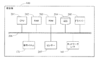
図2は、複合機における制御系のハードウェア構成図である。本実施形態の複合機100は、CPU(Central Processing Unit)201、RAM(Random Access Memory)202、ROM(Read Only Memory)203、HDD(Hard Disk Drive)204及び画像読取部120、画像形成部140における各駆動部に対応するドライバー205が内部バス206を介して接続されている。ROM203やHDD204等はプログラムを格納しており、CPU201はその制御プログラムの指令にしたがって複合機100を制御する。例えば、CPU201はRAM202を作業領域として利用し、ドライバー205とデータや命令を授受することにより上記各駆動部の動作を制御する。また、HDD204は、画像読取部120により得られた画像データや、他の機器からネットワークインターフェイス161を通じて受信した画像データの蓄積にも用いられる。
FIG. 2 is a hardware configuration diagram of a control system in the multifunction machine. The
内部バス206には、操作パネル171や各種のセンサー207も接続されている。操作パネル171は、ユーザーの操作を受け付け、その操作に基づく信号をCPU201に供給する。また、操作パネル171は、CPU201からの制御信号にしたがって自身が備えるディスプレイに操作画面を表示する。センサー207は、プラテンカバー102の開閉検知センサーや原稿台上の原稿検知センサー、定着器の温度センサー、搬送される用紙又は原稿の検知センサーなど各種のセンサーを含む。
An
CPU201は、例えばROM203に格納されたプログラムを実行することで、以下の各手段(機能ブロック)を実現するとともに、これらセンサーからの信号に応じて各手段の動作を制御する。
The
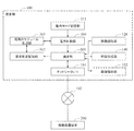
図3は、本実施形態の複合機の機能ブロック図である。図3に示すように、本実施形態の複合機100は、通信部301、要求頻度監視部302、起動スケジュール生成部303、電力制御部304、及び動作モード切替部311を備える。
FIG. 3 is a functional block diagram of the MFP according to the present embodiment. As illustrated in FIG. 3, the multifunction peripheral 100 according to the present embodiment includes a
動作モード切替部311は、上述の待機モードと低消費電力モードとを含む複数の動作モードを切り替える。待機モードには、複合機100が実行可能な各機能(画像読取機能、画像形成機能、ファクシミリ送受信機能、ネットワーク送受信機能)中の1の機能のみが直ちに実行できる状態にあるモードの他、一部の複数の機能のみが直ちに実行できる状態にあるモード(例えば、定着器等電力消費の大きい機器への電源供給が停止され、画像形成機能は直ちに実行できないモード)や全機能が直ちに実行できる状態にあるモードが含まれる。また、低消費電力モードでは、複合機100の一部のみに電力を供給することで、低消費電力モードから他の動作モードへの移行条件を満たすか否かを検知することができる状態に、複合機100は維持される。例えば、移行条件を満たすか否かの検知に無関係なセンサー(例えば、プラテンカバー開閉検知センサーや原稿検知センサー等)、RAM202、HDD204、各ユニット(画像読取部120、画像形成部140)等への電力供給が停止される。また、CPU201に対しても、上記検知に必要な最小限の電力のみが供給される。
The operation
本実施形態では、例えば、複合機100が待機モードにある場合、複合機100への指示が入力されない状態が予め指定された一定時間継続すると、動作モード切替部311は待機モードから低消費電力モードへ動作モードを切り替える。また、複合機100が低消費電力モードにある場合、操作パネル171を通じてユーザーによる指示の入力があると、動作モード切替部311は、ユーザーの指示内容に応じて低消費電力モードから待機モードへ動作モードを切り替える。
In the present embodiment, for example, when the
通信部301は、ネットワークインターフェイス161を介してネットワーク162に接続し、ネットワーク162に接続された他の機器(例えば、情報処理端末200)と通信する。例えば、情報処理端末200から画像形成指示とともに画像データが入力された場合、通信部301は入力された画像データを画像形成部140に入力する。また、情報処理端末200から画像読取部120における画像読取指示が入力された場合、通信部301は画像読取部120において生成された画像データを情報処理端末200へ送信する。また、情報処理端末200から画像格納指示とともに画像データが入力された場合、通信部301は入力された画像データを画像格納部312に入力する。さらに、情報処理端末200から画像格納部312に格納された画像データの読出指示が入力された場合、通信部301は指定された画像データを画像格納部312から読み出し、読み出した画像データを情報処理端末200へ送信する。なお、画像格納部312は、例えば、HDD204により実現される。
The
要求頻度監視部302は、通信部301が受信した画像処理要求の頻度を示す情報(要求頻度情報)を取得する。画像処理要求とは、上記で例示したような、画像形成指示、画像読取指示、画像格納指示、画像読出指示等の複合機100の機能(画像処理機能)の実行を伴う指示であり、ブロードキャストのように、複合機100の機能の実行を伴わない指示は含まない。
The request
特に限定されないが、本実施形態では、要求頻度監視部302は、ネットワーク162を通じた画像処理要求が通信部301に入力されたときの時刻情報を要求頻度情報として記録する。時刻情報とは、例えば、年、月、日、時、分、秒を特定可能な情報である。
Although not particularly limited, in the present embodiment, the request
起動スケジュール生成部303は、要求頻度監視部302が取得した要求頻度情報に基づいて、通信部301の起動スケジュールを生成する。ここで、起動スケジュールは、通信部301に対する電力供給モードを時間帯ごとに規定する。後述のように、本実施形態では、電力供給モードは通信部301の起動時間が異なる複数の電力供給モードを含む。
The activation
本実施形態では、まず、起動スケジュール生成部303は、予め指定された期間(例えば、1週間や1ヶ月)内の要求頻度情報を要求頻度監視部302から取得する。そして、起動スケジュール生成部303は、画像処理要求が通信部301に入力された回数を指定された時間帯ごとに計数する。当該時間帯の区分方法は特に限定されない。例えば、1日を24の時間帯に区分、すなわち、1時間ごとに区分し、各時間帯において入力された画像処理要求を計数する構成を採用することができる。また、各曜日の時間帯ごとに画像処理要求を計数する構成や、営業日と休業日のそれぞれについて、時間帯ごとに画像処理要求を計数する構成を採用することもできる。
In this embodiment, first, the activation
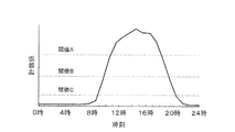
また、本実施形態では、起動スケジュール生成部303は、予め指定された閾値と、各時間帯の画像処理要求の計数値とを比較することで起動スケジュールを生成する。図4は、起動スケジュール生成部303が、予め指定された期間内について計数した各時間帯の計数値の一例を示す図である。図4において、横軸は、時刻(時間帯)に対応し、縦軸は、計数値に対応する。図4では、0時から1時のように、1時間ごとの各時間帯について画像処理要求が計数されており、各時間帯の中央(0時から1時の時間帯であれば、0時30分の位置)にその計数値を記載している。
In the present embodiment, the activation
また、図4では、上述の閾値も併せて図示している。この例では、3つの閾値(閾値A、閾値B、閾値C)が予め設定されており、各時間帯の計数値と各閾値との大小関係により、起動スケジュールが決定される。すなわち、各計数値が、閾値C未満、閾値C以上閾値B未満、閾値B以上閾値A未満、閾値A以上のいずれの範囲に属するかにより、通信部301への電力供給方法(電力供給モード)が選択される。
FIG. 4 also illustrates the above-described threshold value. In this example, three threshold values (threshold value A, threshold value B, and threshold value C) are set in advance, and the activation schedule is determined based on the magnitude relationship between the count value of each time zone and each threshold value. That is, the power supply method (power supply mode) to the
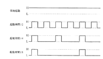
図5は、本実施形態で選択可能な電力供給モードの一例を示す図である。図5において、「Highレベル」が通信部301へ電力を供給する状態に対応し、「Lowレベル」が通信部301へ電力を供給しない状態(通信部301への電力供給を遮断する状態)に対応する。なお、通信部301への電力の供給及び遮断は、通信部301への電力供給経路にスイッチを設け、当該スイッチのオン状態とオフ状態とを切り替える等の公知の任意の手法により実現することができる。
FIG. 5 is a diagram illustrating an example of a power supply mode that can be selected in the present embodiment. In FIG. 5, “High level” corresponds to a state where power is supplied to the
ここでは、電力供給モードとして、「常時起動」、「起動時間1/2」、「起動時間1/4」、「起動時間1/8」の4つを例示している。「常時起動」は、通信部301を常時起動する電力供給モードであり、通信部301に電力が常時供給される。
Here, four examples of “always start”, “start time 1/2”, “start time 1/4”, and “start time 1/8” are illustrated as power supply modes. “Always activated” is a power supply mode in which the
「起動時間1/2」は、「常時起動」に対して通信部301の起動時間を1/2にする電力供給モードであり、通信部301に予め指定された時間周期で電力の供給及び遮断が繰り返される。この電力供給モードでは、例えば、電力供給が10秒間継続された後、電力供給が10秒間遮断される。
“Start-up time 1/2” is a power supply mode in which the start-up time of the
「起動時間1/4」は、「常時起動」に対して通信部301の起動時間を1/4にする電力供給モードであり、通信部301に予め指定された時間周期で電力の供給及び遮断が繰り返される。この電力供給モードでは、例えば、電力供給が10秒間継続された後、電力供給が30秒間遮断される。
“Start-up time ¼” is a power supply mode in which the start-up time of the
「起動時間1/8」は、「常時起動」に対して通信部301の起動時間を1/8にする電力供給モードであり、通信部301に予め指定された時間周期で電力の供給及び遮断が繰り返される。この電力供給モードでは、例えば、電力供給が10秒間継続された後、電力供給が70秒間遮断される。
“Start-up time 1/8” is a power supply mode in which the start-up time of the
図4の例では、0時から9時までの時間帯及び20時から24時までの時間帯の計数値が閾値C未満になっている。この場合、起動スケジュール生成部303は、これらの時間帯の電力供給モードとして「起動時間1/8」を選択した起動スケジュールを生成する。
In the example of FIG. 4, the count values in the time zone from 0:00 to 9:00 and the time zone from 20:00 to 24:00 are less than the threshold value C. In this case, the activation
また、9時から10時までの時間帯及び19時から20時までの時間帯は、計数値が閾値C以上閾値B未満になっている。この場合、起動スケジュール生成部303は、これらの時間帯の電力供給モードとして「起動時間1/4」を選択した起動スケジュールを生成する。
Further, in the time zone from 9 o'clock to 10 o'clock and the time zone from 19 o'clock to 20 o'clock, the count value is greater than or equal to threshold C and less than threshold B. In this case, the activation
また、10時から11時までの時間帯及び18時から19時までの時間帯は、計数値が閾値B以上閾値A未満になっている。この場合、起動スケジュール生成部303は、これらの時間帯の電力供給モードとして「起動時間1/2」を選択した起動スケジュールを生成する。
Further, in the time zone from 10 o'clock to 11 o'clock and the time zone from 18 o'clock to 19 o'clock, the count value is greater than or equal to threshold B and less than threshold A. In this case, the activation
また、11時から18時までの時間帯は、計数値が閾値A以上になっている。この場合、起動スケジュール生成部303は、これらの時間帯の電力供給モードとして「常時起動」を選択した起動スケジュールを生成する。
Further, in the time zone from 11:00 to 18:00, the count value is equal to or greater than the threshold value A. In this case, the activation
なお、起動スケジュール生成部303による要求頻度情報の取得タイミングは特に限定されない。本実施形態では、予め指定された時間間隔(例えば、1日)で起動スケジュール生成部303が、予め指定された期間の要求頻度情報を要求頻度監視部302から取得する構成になっている。起動スケジュール生成部303は、要求頻度情報を取得する都度、新たな起動スケジュールを生成する。
The acquisition timing of the request frequency information by the activation
電力制御部304は、複合機100が低消費電力モードである場合、起動スケジュール生成部303が生成した起動スケジュールにしたがって通信部301に対する電力供給モードを切り替える。特に限定されないが、本実施形態では、電力制御部304は、上述の通信部301に対する4つの電力供給モードを切り替える。なお、本実施形態では、電力制御部304は、動作モードを切り替える際に動作モード切替部311からなされる通知により、複合機100が低消費電力モードにあることを認識する構成になっている。
When the multifunction peripheral 100 is in the low power consumption mode, the
電力制御部304による、起動スケジュール生成部303からの起動スケジュールの取得方法は特に限定されない。本実施形態では、電力制御部304は、複合機100が低消費電力モードになったときに起動スケジュール生成部303から起動スケジュールを取得する構成を採用している。このような構成に限らず、例えば、電力制御部304が所定の時間間隔で起動スケジュールを取得する構成や、起動スケジュールが起動スケジュール生成部303により更新された際に電力制御部304が起動スケジュールを取得する構成等を採用することもできる。
The method for acquiring the activation schedule from the activation
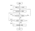
図6は、複合機100が実行する電力制御手順の一例を示すフロー図である。当該手順は、動作モード切替部311が複合機100の動作モードを低消費電力モードに切り替えたことをトリガーとして開始する。
FIG. 6 is a flowchart illustrating an example of a power control procedure executed by the multifunction peripheral 100. The procedure starts when the operation
本手順が開始すると、電力制御部304が起動スケジュール生成部303の起動スケジュールを取得する(ステップS601)。このとき、電力制御部304は、その時点の時刻情報を取得し、取得した時刻情報と取得した起動スケジュールから、起動スケジュールにより指定された電力供給モードを認識する。起動スケジュールから電力供給モードを認識した電力制御部304は、通信部301に対する電力供給モードを、認識した電力供給モードにする(ステップS602)。電力制御部304は当該電力供給モードを、起動スケジュールにおいて異なる電力供給モードが指定されるまで維持する(ステップS603No、S604No)。起動スケジュールにおいて異なる電力供給モードが指定された時刻が到来すると、電力制御部304は起動スケジュールにしたがって電力供給モードを変更する(ステップS603Yes、S602)。
When this procedure starts, the
一方、電力制御部304が電力供給モードを、特定の電力供給モードに維持している状況下において、ユーザーが操作パネル171を通じて低消費電力モードから待機モードへの移行を伴う指示を入力した場合、あるいは、通信部301に電力が供給されているタイミングでネットワーク162を通じて低消費電力モードから待機モードへの移行を伴う指示が入力された場合、動作モード切替部311は、複合機100の動作モードを低消費電力モードから待機モードへ切り替える。このとき、電力制御部304には、動作モード切替部311からその旨が通知される(ステップS604Yes)。このとき、電力制御部304は、通信部301に対する電力供給モードを、「常時起動」に変更する(ステップS605)。
On the other hand, in a situation where the
なお、通信部301に電力が供給されていないタイミングでは、通信部301はネットワーク162を通じた指示を認識することはできない。そのため、ネットワーク162を通じた指示(信号)によって、通信部301への電力供給が遮断されている状態が解除されることはない。
Note that the
また、通信部301に電力が供給されていないタイミングで、例えば、情報処理端末200から複合機100に対して出力された指示(信号)は、通信部301に受け付けられない。この場合、情報処理端末200では、所定の時間間隔をおいて指示が再送信されるリトライ動作が実行される。通信部301の起動時間を短縮した電力供給モードが電力制御部304により選択されている状況下であっても、通信部301へ電力が供給されている間にリトライ動作が実行されるように、電力供給モードにおける電力供給周期、あるいは、リトライ動作の繰り返し時間間隔を設計することで、当該指示を通信部301に認識させることが可能である。
Further, for example, an instruction (signal) output from the
また、要求頻度監視部302による要求頻度情報の取得は、通信部301の起動時間を短縮した電力供給モードが電力制御部304により選択されている状況下であっても継続される。この場合、要求頻度監視部302は、通信部301へ電力が供給されている間に通信部301に入力された画像処理要求のみを記録することになる。
The acquisition of the request frequency information by the request
以上説明したように、この複合機100では、現実になされた画像処理要求の頻度に応じて、通信部301が起動している時間(通信部301に電力が供給されている時間)を可変させることができる。そのため、上述のように、画像処理要求が多い時間帯には通信部301が起動している時間を長くし、画像処理要求が少ない時間帯には通信部301が起動している時間を短くする構成を実現することができる。したがって、通信部301が起動している時間を、ユーザーの使用環境に応じて変化させることができる。
As described above, in the
また、複合機100における処理に関係のない信号に対応して通信部301は起動されることがなく、また、要求頻度が少ない時間帯では、通信部301が起動していない時間を長くすることができる。その結果、通信部301の消費電力をより低減することができる。一方、要求頻度が多い時間帯では、通信部301が起動している時間が長くなるため、リトライ動作を待つことなく画像処理要求が複合機100に受信される。そのため、ユーザーの待ち時間が異常に増大することを抑制することができる。
In addition, the
加えて、通信部301が起動していない時間帯に到達した複合機100宛ての信号は、通信部301によって受信することができないが、当該信号は、信号送信元におけるリトライ動作において複合機100に受信される。
In addition, a signal addressed to the
なお、上述した実施形態は本発明の技術的範囲を制限するものではなく、既に記載したもの以外でも、本発明の範囲内で種々の変形や応用が可能である。例えば、上記実施形態では、起動スケジュールを「常時起動」、「起動時間1/2」、「起動時間1/4」、「起動時間1/8」の4つで構成したが、より多くの電力供給モード、あるいは、より少ない電力供給モードを使用して起動スケジュールを構成してもよい。 The above-described embodiments do not limit the technical scope of the present invention, and various modifications and applications other than those already described are possible within the scope of the present invention. For example, in the above-described embodiment, the activation schedule is configured with four of “always activated”, “activation time 1/2”, “activation time 1/4”, and “activation time 1/8”, but more power is required. The activation schedule may be configured using a supply mode or a lower power supply mode.
また、図6に示したフローチャートは、等価な作用を奏する範囲において、各ステップの順序を適宜変更可能である。例えば、図6では、最初に起動スケジュールを取得する構成としたが、電力制御部304は、当該手順が開始される前に、予め起動スケジュールを取得していてもよい。
In the flowchart shown in FIG. 6, the order of the steps can be changed as appropriate within the range where the equivalent action is achieved. For example, in FIG. 6, the startup schedule is acquired first, but the
加えて、上述の実施形態では、デジタル複合機により本発明を具体化したが、デジタル複合機に限らず、スキャナ、プリンタ、複写機等の任意の画像処理装置に本発明を適用することも可能である。 In addition, in the above-described embodiment, the present invention is embodied by a digital multifunction peripheral. However, the present invention can be applied not only to a digital multifunction peripheral but also to an arbitrary image processing apparatus such as a scanner, a printer, and a copying machine. It is.
本発明によれば、低消費電力モード時のネットワーク通信に係る電力消費をより低減することができ、画像処理装置として有用である。 ADVANTAGE OF THE INVENTION According to this invention, the power consumption concerning the network communication at the time of a low power consumption mode can be reduced more, and it is useful as an image processing apparatus.
100 複合機(画像処理装置)
161 ネットワークインターフェイス
162 ネットワーク
200 情報処理端末(他の機器)
301 通信部
302 要求頻度監視部
303 起動スケジュール生成部
304 電力制御部
311 動作モード切替部
100 MFP (image processing device)
Claims (3)
ネットワークインターフェイスを介してネットワークに接続し、当該ネットワークに接続された他の機器と通信する通信部と、
前記通信部が受信した画像処理要求の頻度を示す情報を取得する要求頻度監視部と、
前記要求頻度監視部が取得した要求頻度情報に基づいて、前記通信部の起動スケジュールを生成する起動スケジュール生成部と、
画像処理装置が前記低消費電力モードである場合、前記起動スケジュール生成部が生成した起動スケジュールにしたがって前記通信部に対する電力供給モードを切り替える電力制御部と、
を備える、画像処理装置。 An image processing apparatus comprising: a standby mode in which image processing can be performed; and a low power consumption mode that consumes less power than the standby mode,
A communication unit that connects to a network via a network interface and communicates with other devices connected to the network;
A request frequency monitoring unit that acquires information indicating the frequency of image processing requests received by the communication unit;
Based on the request frequency information acquired by the request frequency monitoring unit, an activation schedule generation unit that generates an activation schedule of the communication unit;
When the image processing apparatus is in the low power consumption mode, a power control unit that switches a power supply mode for the communication unit according to a startup schedule generated by the startup schedule generation unit;
An image processing apparatus comprising:
Priority Applications (2)
| Application Number | Priority Date | Filing Date | Title |
|---|---|---|---|
| JP2014236415A JP6050803B2 (en) | 2014-11-21 | 2014-11-21 | Image processing device |
| US14/938,864 US9544458B2 (en) | 2014-11-21 | 2015-11-12 | Image processing apparatus including a standby mode |
Applications Claiming Priority (1)
| Application Number | Priority Date | Filing Date | Title |
|---|---|---|---|
| JP2014236415A JP6050803B2 (en) | 2014-11-21 | 2014-11-21 | Image processing device |
Publications (2)
| Publication Number | Publication Date |
|---|---|
| JP2016100746A true JP2016100746A (en) | 2016-05-30 |
| JP6050803B2 JP6050803B2 (en) | 2016-12-21 |
Family
ID=56011472
Family Applications (1)
| Application Number | Title | Priority Date | Filing Date |
|---|---|---|---|
| JP2014236415A Expired - Fee Related JP6050803B2 (en) | 2014-11-21 | 2014-11-21 | Image processing device |
Country Status (2)
| Country | Link |
|---|---|
| US (1) | US9544458B2 (en) |
| JP (1) | JP6050803B2 (en) |
Cited By (2)
| Publication number | Priority date | Publication date | Assignee | Title |
|---|---|---|---|---|
| JP2018094869A (en) * | 2016-12-16 | 2018-06-21 | 京セラドキュメントソリューションズ株式会社 | Image formation apparatus and image formation system |
| US11409479B2 (en) | 2020-10-29 | 2022-08-09 | Kyocera Document Solutions Inc. | Image forming apparatus |
Citations (2)
| Publication number | Priority date | Publication date | Assignee | Title |
|---|---|---|---|---|
| JP2012015655A (en) * | 2010-06-29 | 2012-01-19 | Sharp Corp | Image processing system, management device, image processing device, power control method for image processing device, power control program and recording medium |
| JP2012103580A (en) * | 2010-11-12 | 2012-05-31 | Sharp Corp | Image forming apparatus |
Family Cites Families (6)
| Publication number | Priority date | Publication date | Assignee | Title |
|---|---|---|---|---|
| US7583396B2 (en) * | 2002-10-28 | 2009-09-01 | Canon Kabushiki Kaisha | Printing system, printing method, and computer program |
| JP2009277057A (en) | 2008-05-15 | 2009-11-26 | Ricoh Co Ltd | Network equipment and method for controlling power of network equipment |
| JP2011109252A (en) * | 2009-11-13 | 2011-06-02 | Canon Inc | Communication device, control method of communication device, and program |
| JP5586924B2 (en) * | 2009-11-24 | 2014-09-10 | キヤノン株式会社 | Image forming apparatus |
| JP5251969B2 (en) * | 2010-12-20 | 2013-07-31 | コニカミノルタビジネステクノロジーズ株式会社 | Image forming apparatus |
| JP5516497B2 (en) * | 2011-04-28 | 2014-06-11 | ブラザー工業株式会社 | Image forming apparatus and image reading apparatus |
-
2014
- 2014-11-21 JP JP2014236415A patent/JP6050803B2/en not_active Expired - Fee Related
-
2015
- 2015-11-12 US US14/938,864 patent/US9544458B2/en not_active Expired - Fee Related
Patent Citations (2)
| Publication number | Priority date | Publication date | Assignee | Title |
|---|---|---|---|---|
| JP2012015655A (en) * | 2010-06-29 | 2012-01-19 | Sharp Corp | Image processing system, management device, image processing device, power control method for image processing device, power control program and recording medium |
| JP2012103580A (en) * | 2010-11-12 | 2012-05-31 | Sharp Corp | Image forming apparatus |
Cited By (2)
| Publication number | Priority date | Publication date | Assignee | Title |
|---|---|---|---|---|
| JP2018094869A (en) * | 2016-12-16 | 2018-06-21 | 京セラドキュメントソリューションズ株式会社 | Image formation apparatus and image formation system |
| US11409479B2 (en) | 2020-10-29 | 2022-08-09 | Kyocera Document Solutions Inc. | Image forming apparatus |
Also Published As
| Publication number | Publication date |
|---|---|
| JP6050803B2 (en) | 2016-12-21 |
| US9544458B2 (en) | 2017-01-10 |
| US20160150114A1 (en) | 2016-05-26 |
Similar Documents
| Publication | Publication Date | Title |
|---|---|---|
| US11792337B2 (en) | Communication apparatus having power related predetermined processing, method of controlling the same, and storage medium | |
| US10110764B2 (en) | Image forming apparatus that shifts into different power saving states and control method thereof | |
| US9076102B2 (en) | Image forming apparatus, host apparatus, image forming system having the same, and method of controlling power thereof | |
| US8539267B2 (en) | Image forming apparatus and power management method thereof | |
| JP5909896B2 (en) | Printing apparatus, printing system, and printing method | |
| JP2011025671A (en) | Image forming device, and low electric power control method therefor | |
| US9742946B2 (en) | System and method for shifting electric power modes in an image forming system | |
| JP6022524B2 (en) | Electronics | |
| JP6050803B2 (en) | Image processing device | |
| US9571686B2 (en) | Electronic device with energy saving mode and error state detection | |
| JP5989632B2 (en) | Electronic equipment and power control program | |
| JP5866276B2 (en) | Power management system | |
| JP6486193B2 (en) | Communication apparatus, control method, and program | |
| JP6233533B2 (en) | Power supply apparatus and image processing apparatus | |
| US10623589B2 (en) | Image formation system and control method of image formation system capable of determining mode shift condition | |
| JP7423465B2 (en) | Apparatus and method for reducing energy usage in multifunctional devices | |
| JP6439939B2 (en) | Electronic equipment and power control program | |
| JP6568397B2 (en) | Image forming apparatus and system including the same | |
| JP2016012774A (en) | Image processing apparatus and image processing system | |
| JP6264561B2 (en) | Job transmission device, job execution device, job execution system, program, and job transmission method | |
| JP2016143122A (en) | Operation apparatus and operation method | |
| JP2016101701A (en) | Image forming device | |
| JP2015104880A (en) | Peripheral device, terminal, power-saving control system, power-saving control method, and power-saving control program | |
| JP2010079138A (en) | Image forming apparatus and image formation system |
Legal Events
| Date | Code | Title | Description |
|---|---|---|---|
| A621 | Written request for application examination |
Free format text: JAPANESE INTERMEDIATE CODE: A621 Effective date: 20160520 |
|
| A871 | Explanation of circumstances concerning accelerated examination |
Free format text: JAPANESE INTERMEDIATE CODE: A871 Effective date: 20160520 |
|
| A975 | Report on accelerated examination |
Free format text: JAPANESE INTERMEDIATE CODE: A971005 Effective date: 20160803 |
|
| A977 | Report on retrieval |
Free format text: JAPANESE INTERMEDIATE CODE: A971007 Effective date: 20160805 |
|
| A131 | Notification of reasons for refusal |
Free format text: JAPANESE INTERMEDIATE CODE: A131 Effective date: 20160817 |
|
| A521 | Request for written amendment filed |
Free format text: JAPANESE INTERMEDIATE CODE: A523 Effective date: 20160930 |
|
| TRDD | Decision of grant or rejection written | ||
| A01 | Written decision to grant a patent or to grant a registration (utility model) |
Free format text: JAPANESE INTERMEDIATE CODE: A01 Effective date: 20161026 |
|
| A61 | First payment of annual fees (during grant procedure) |
Free format text: JAPANESE INTERMEDIATE CODE: A61 Effective date: 20161125 |
|
| R150 | Certificate of patent or registration of utility model |
Ref document number: 6050803 Country of ref document: JP Free format text: JAPANESE INTERMEDIATE CODE: R150 |
|
| LAPS | Cancellation because of no payment of annual fees |