JP2016055226A - Vibrating sieve - Google Patents
Vibrating sieve Download PDFInfo
- Publication number
- JP2016055226A JP2016055226A JP2014182239A JP2014182239A JP2016055226A JP 2016055226 A JP2016055226 A JP 2016055226A JP 2014182239 A JP2014182239 A JP 2014182239A JP 2014182239 A JP2014182239 A JP 2014182239A JP 2016055226 A JP2016055226 A JP 2016055226A
- Authority
- JP
- Japan
- Prior art keywords
- drive shaft
- movable frame
- shaft
- drive
- vibration
- Prior art date
- Legal status (The legal status is an assumption and is not a legal conclusion. Google has not performed a legal analysis and makes no representation as to the accuracy of the status listed.)
- Pending
Links
Images


Landscapes
- Combined Means For Separation Of Solids (AREA)
Abstract
Description
本発明は、水平型の振動ふるい機に関する。 The present invention relates to a horizontal vibration sieve.
水平型の振動ふるい機においては、スクリーン部を有する可動枠の上部に、可動枠を振動させるための起振装置の主体部が設置されている。起振装置の主体部は、可動枠の幅方向に延びる駆動軸と、この駆動軸と平行状態に配置された従動軸を備える。これら駆動軸および従動軸は、可動枠の幅方向の両側に設けられた軸受によりそれぞれ回転可能に支持されているとともに、それぞれの両端部が可動枠の外側まで突出していて、それらの各両端部に偏心用錘が装着されている。駆動軸には駆動ギヤが設けられ、従動軸には従動ギヤが設けられていて、それら駆動ギヤと従動ギヤが噛み合っている。そして、可動枠を弾性的に支持するベース部側には、駆動源となるモータが設置されていて、このモータの回転軸と前記駆動軸の一端部との間に、ベルトとプーリ―を用いたベルト伝動機構が設けられている。モータによりベルト伝動機構を介して駆動軸を前記偏心用錘ごと一方向に回転させると、駆動ギヤおよび従動ギヤを介して従動軸が偏心用錘ごと前記駆動軸とは反対方向へ回転される。これにより起振装置の主体部に偏心用錘の振り回し荷重による振動力が発生し、その振動力により、可動枠にはスクリーン部上の対象物を一方向へ移送させる振動力が発生する。この振動力により、スクリーン部上の対象物がふるわれながら一方向へ移送される構成となっている。 In a horizontal vibration sieving machine, a main part of a vibration generator for vibrating the movable frame is installed on the upper part of the movable frame having a screen portion. The main part of the vibration generator includes a drive shaft extending in the width direction of the movable frame, and a driven shaft arranged in parallel with the drive shaft. The drive shaft and the driven shaft are rotatably supported by bearings provided on both sides of the movable frame in the width direction, and both end portions protrude to the outside of the movable frame. Eccentric weight is attached to The drive shaft is provided with a drive gear, the driven shaft is provided with a driven gear, and the drive gear and the driven gear are engaged with each other. A motor serving as a drive source is installed on the side of the base portion that elastically supports the movable frame, and a belt and a pulley are used between the rotation shaft of the motor and one end portion of the drive shaft. The belt transmission mechanism was provided. When the drive shaft is rotated in one direction together with the eccentric weight by the motor via the belt transmission mechanism, the driven shaft is rotated in the opposite direction to the drive shaft together with the eccentric weight via the drive gear and the driven gear. As a result, a vibration force due to the swinging load of the eccentric weight is generated in the main portion of the vibration generating device, and a vibration force for transferring the object on the screen portion in one direction is generated in the movable frame by the vibration force. With this vibration force, the object on the screen is moved in one direction while being shaken.
このような構成の水平型の振動ふるい機においては、起振装置の主体部となる駆動軸と従動軸が可動枠の幅寸法よりも長く、可動枠の外側に位置させて偏心用錘が設けられている。このため、駆動軸および従動軸は、長さが長くて重い。しかも、それら駆動軸および従動軸を回転自在に支持する軸受を可動枠の左右両側に2個ずつ合計4個必要としているが、それら軸受も、各軸を支えるために強度が強く重いものが必要となり、起振装置の主体部が重くなる。また、これに伴い、偏心用錘も重くする必要がある。このように、従来構成のものでは、起振装置の主体部の重量が大きいため、起振装置の駆動源となるモータの駆動電力も大きくなってしまうという課題がある。 In the horizontal vibration sieve machine having such a configuration, the drive shaft and the driven shaft, which are the main parts of the vibration generator, are longer than the width of the movable frame and are provided outside the movable frame with an eccentric weight. It has been. For this reason, the drive shaft and the driven shaft are long and heavy. Moreover, a total of four bearings are required on each of the left and right sides of the movable frame to rotatably support the drive shaft and the driven shaft, but these bearings must also be strong and heavy to support each shaft. Thus, the main part of the vibration generator becomes heavy. Along with this, the eccentric weight needs to be heavy. Thus, in the thing of the conventional structure, since the weight of the main part of a vibration generator is large, there exists a subject that the drive electric power of the motor used as the drive source of a vibration generator will also become large.
そこで、本発明は、起振装置の主体部を軽量化できるとともに、駆動源の駆動電力の低減化を図ることができる水平型の振動ふるい機を提供することを目的とする。 SUMMARY OF THE INVENTION An object of the present invention is to provide a horizontal vibration sieving machine that can reduce the weight of the main part of the vibration generator and can reduce the drive power of the drive source.
本発明は、ベース部に弾性的に支持して設けられ振動に伴い対象物をふるうスクリーン部を有する可動枠と、この可動枠を振動させる起振装置と、を備え、前記スクリーン部は水平状態に配置されていて、前記起振装置により前記可動枠を振動させることに伴い前記スクリーン部上の対象物をふるいながら一方向へ移送する構成の水平型の振動ふるい機において、前記起振装置は、前記可動枠にあって前記対象物の移送方向に対して直交する幅方向のほぼ中央部に設置される主体部と、前記ベース部側に設置される駆動源と、を備え、前記主体部は、前記可動枠の幅方向に延び前記可動枠の幅内に位置させて一対の偏心用錘を有し前記駆動源により前記偏心用錘ごと回転される駆動軸と、この駆動軸と平行状態に配置され前記可動枠の幅内に位置させて一対の偏心用錘を有し前記駆動軸の回転に伴い前記偏心用錘ごと前記駆動軸とは反対方向に回転される従動軸と、を備えた構成としている。 The present invention comprises a movable frame having a screen portion that is elastically supported by a base portion and shakes an object in accordance with vibration, and a vibration generator that vibrates the movable frame, and the screen portion is in a horizontal state. In the horizontal vibratory sieve machine configured to move in one direction while sieving the object on the screen unit as the movable frame is vibrated by the vibratory apparatus, the vibratory apparatus comprises: A main body part installed in a substantially central part in a width direction perpendicular to the transfer direction of the object in the movable frame, and a drive source installed on the base part side, and the main body part Has a pair of eccentric weights extending in the width direction of the movable frame and positioned within the width of the movable frame and rotated by the drive source together with the eccentric weight, and in a state parallel to the drive shaft Placed within the width of the movable frame By location has a configuration provided with a driven shaft which is rotated in a direction opposite to the each eccentric for weight the drive shaft with the rotation of the drive shaft has a pair of eccentric for weight.
起振装置の主体部において、駆動軸に設けられる一対の偏心用錘、および従動軸に設けられる一対の偏心用錘は、それぞれ可動枠の幅内に納められている。このため、駆動軸および従動軸は、長さを従来に比べて短くすることができ、その分重量も小さくできる。これに伴い、これら駆動軸および従動軸を回転自在に支持する軸受や偏心用錘も軽量化することが可能になり、起振装置の主体部を軽量化することができる。これに伴い、起振装置における駆動源の駆動電力の低減化も図ることが可能となる。 In the main part of the vibration generator, the pair of eccentric weights provided on the drive shaft and the pair of eccentric weights provided on the driven shaft are respectively stored within the width of the movable frame. For this reason, the drive shaft and the driven shaft can be shortened in length compared to the conventional one, and the weight can be reduced accordingly. Accordingly, it is possible to reduce the weight of the bearing and the eccentric weight that rotatably support the drive shaft and the driven shaft, and the main portion of the vibration generator can be reduced in weight. Accordingly, it is possible to reduce the driving power of the driving source in the vibration generator.
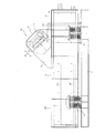
以下、本発明による水平型振動ふるい機の一実施形態について図面を参照して説明する。まず、図1から図3において、スクリーン部1Aおよび1Bを有する可動枠2は、図2において左右方向に長い矩形状をなしていて、ベース部3に複数のスプリング4を介して弾性的に支持されている。この場合、スクリーン部1Aおよび1Bは、上下に2段あり、それぞれほぼ水平状態に配置されている。スクリーン部1Aおよび1Bにはそれぞれふるい用の孔部が多数形成されていて、下段のスクリーン部1Bの孔部は、上段のスクリーン部1Aの孔部よりやや小さく設定されている。この場合、振動ふるい機の運転時にスクリーン部1A,1B上の対象物の移送方向は、可動枠2の長手方向の一方向となる、図1および図2の矢印A方向である。
Hereinafter, an embodiment of a horizontal vibrating screen according to the present invention will be described with reference to the drawings. First, in FIGS. 1 to 3, the movable frame 2 having the screen portions 1 </ b> A and 1 </ b> B has a rectangular shape that is long in the left-right direction in FIG. 2, and is elastically supported by the
可動枠2の上部には、長手方向の中間部に位置させて、長手方向と直交する幅方向の両側に上方へ突出する取付板6が対向する状態に設けられていて、これら取付板6間に主体部取付台7が固定状態に設けられている。主体部取付台7は、底板部7aの両端部に立上がり部7bを有したコ字形をなしていて、底板部7aが可動枠2に対して約45度傾斜した状態で取り付けられている。この場合、底板部7aは、図2の正面側から見て右下がりに傾斜している。その傾斜した底板部7aに、起振装置8の主体部9が設置されている。したがって、起振装置8の主体部9は、可動枠2の上部にあって、対象物の移送方向である矢印A方向に対して直交する幅方向のほぼ中央部に設置されている。
At the upper part of the movable frame 2, there are provided mounting plates 6 that are positioned in the middle part in the longitudinal direction and project upward on both sides in the width direction perpendicular to the longitudinal direction. The main
起振装置8は、可動枠2ひいてはスクリーン部1A,1Bを振動させるためのもので、主体部9と、駆動源となるモータ10と、を備える。モータ10は、ベース部3にあって一方の取付板6の近傍に位置させて設けられたモータ取付台11上に固定状態に設けられている。このモータ10は、回転軸10aを取付板6側に向けている。
The
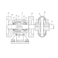
次に、主体部9について、図4から図6も参照して説明する。主体部9は、可動枠2の幅方向に延びる駆動軸12と、この駆動軸12と所定の間隔を存した状態で当該駆動軸12と平行状態に配置された従動軸13を備えている。これら駆動軸12と従動軸13は、底板部7aに固定状態に設けられたギヤケース14を軸方向に貫通している。このうち、駆動軸12は、図6に示すように、ギヤケース14の左右両側部に設けられたサイドカバー15に一対の軸受16を介して回転可能に支持されている。各軸受16は、この場合テーパベアリングと呼ばれるもので、キャップ17により外側から覆われている。なお、従動軸13も、詳細には示されていないが、駆動軸12と同様に、ギヤケース14の左右両側部に設けられたサイドカバー15に一対の軸受を介して回転可能に支持されている。各軸受は、キャップ17により外側から覆われている。
Next, the
駆動軸12には、左右のキャップ17から突出した外側に位置させて一対の偏心用錘18が当該駆動軸12と一体に回転するように取り付けられている。駆動軸12において前記モータ10側の端部は、中間軸19の一端部と周知構成のゴムカップリング20を介して接続されている。ゴムカップリング20は、駆動軸12の端部に固定された連結部21と中間軸19の一端部に固定された連結部22との間を、リング状の連結用ゴム23により連結した構成のものであり、この場合中間軸19の回転を駆動軸12側に伝える。
A pair of
中間軸19の他端部は、主体部取付台7におけるモータ10側の立上がり部7b、およびモータ10側の取付板6を貫通してモータ10側に突出していて、前記ゴムカップリング20と同様な構成のゴムカップリング20を介して前記モータ10の回転軸10aに接続されている(図3参照)。したがって、モータ10の回転軸10aが回転されると、その回転はゴムカップリング20、中間軸19、ゴムカップリング20を介して駆動軸12に伝達され、当該駆動軸12が回転軸10aと同方向に回転される。
The other end portion of the
前記従動軸13の両端部にも、左右のキャップ17の外側に位置させて一対の偏心用錘18が当該従動軸13と一体に回転するように取り付けられている。駆動軸12の一対の偏心用錘18と、従動軸13の一対の偏心用錘18の取付位置は、それら駆動軸12および従動軸13の軸方向で同じ位置となっている。また、駆動軸12の一対の偏心用錘18、および従動軸13の一対の偏心用錘18は、可動枠2の幅内に納められている。
A pair of
図4から図6に示すように、駆動軸12には、ギヤケース14内に位置させて駆動ギヤ25が取り付けられ、また、従動軸13にも、ギヤケース14内に位置させて従動ギヤ26が取り付けられている。さらに、ギヤケース14内には、これら駆動ギヤ25と従動ギヤ26との間に位置させて、偶数個、この場合2個の伝動ギヤ27,28が回転可能に配設されている。そして、一方の伝動ギヤ27は、駆動ギヤ25と他方の伝動ギヤ28と噛み合い、他方の伝動ギヤ28は従動ギヤ26と噛み合っている。ここで、駆動軸12と一体に駆動ギヤ25が、図5で例えば時計回り方向に回転されると、その回転が伝動ギヤ27,28を介して従動ギヤ26に伝えられ、従動ギヤ26ひいては従動軸13が駆動軸12とは反対の、図5で反時計回り方向に回転される。
As shown in FIGS. 4 to 6, a
図2において、正面から見て可動枠2における左側の上部を投入口29としていて、ふるわれる対象物はその投入口29からスクリーン1A上に投入される。なお、振動ふるい機において、通常は起振装置8の主体部9部分は、図1および図3に二点鎖線で示すように、着脱可能なカバー30により覆われていて、点検や修理の際にそのカバー30を外して行う
上記構成において、モータ10の運転を開始させると、回転軸10aの回転が、ゴムカップリング20、中間軸19、ゴムカップリング20を介して駆動軸12に伝わり、当該駆動軸12が偏心用錘18と一体に一方向に回転される。これに伴い、駆動ギヤ25、伝動ギヤ27,28、従動ギヤ26を介して従動軸13が、偏心用錘18と一体に駆動軸12とは反対方向へ回転される。
In FIG. 2, the upper left part of the movable frame 2 when viewed from the front is used as an
このとき、駆動軸12および従動軸13が一回転する間にそれらと一体に回転する偏心用錘18の位置も変わり、それら偏心用錘18から発生する振れ回りの荷重の方向が変わる。駆動軸12の偏心用錘18と従動軸13の偏心用錘18が最も近付いた位置と最も離れた位置では、それら偏心用錘18が一直線上に揃い、かつ振れ回り荷重が反対方向に働くので、振れ回り荷重は相殺しゼロになる。一方、駆動軸12の偏心用錘18と従動軸13の偏心用錘18が、図2において正面から見て右上に位置した状態では、右上方向への振れ回り荷重が合成された荷重が発生し、また、駆動軸12の偏心用錘18と従動軸13の偏心用錘18が、図2において正面から見て左下に位置した状態では、左下方向への振れ回り荷重が合成された荷重が発生する。これにより、起振装置8の主体部9は、図2において、主体部取付台7の底板部7aに直交する方向である矢印B方向の直線状の往復振動を発生させる。
At this time, the position of the
この振動が可動枠2に伝わり、スクリーン部1A,1Bも同方向に振動する。これに伴い、スクリーン部1A上に投入された対象物は、その振動によりふるわれながら移送方向である矢印A方向へ順次移送されるとともに、スクリーン部1Aの孔部から落下した対象物はスクリーン部1Bでふるわれながら同矢印A方向へ順次移送されるようになる。
This vibration is transmitted to the movable frame 2, and the
上記した実施形態によれば、次のような作用効果を得ることができる。
起振装置8の主体部9において、駆動軸12に設けられる一対の偏心用錘18、および従動軸13に設けられる一対の偏心用錘18は、それぞれ可動枠2の幅内に納められている。このため、駆動軸12および従動軸13は、可動枠2の幅内に納めることができ、長さを従来に比べて短くすることができ、その分重量も小さくできる。これに伴い、これら駆動軸12および従動軸13を回転自在に支持する軸受16や偏心用錘18も軽量化することが可能になり、起振装置8の主体部9を軽量化することができる。これに伴い、起振装置8における駆動源となるモータ10の駆動電力の低減化も図ることが可能となる。
According to the above-described embodiment, the following operational effects can be obtained.
In the
この場合、起振装置8の駆動源であるモータ10は、固定側となるベース部3に設けたモータ取付台11に固定しているので、主体部9が発生する振動を受け難く、モータ10の寿命低下を極力防止できる。しかも、モータ10の回転軸10aと駆動軸12との間の回転の伝達にゴムカップリング20を用いているので、駆動軸12側の振動がモータ10側へ一層伝わり難くできる利点があるとともに、連結部のメンテナンスが容易にできる。
In this case, since the
ちなみに、モータの回転軸の回転を、ベルトとプーリを用いたベルト伝動機構を介して駆動軸に伝える構成のものでは、ベルトとプーリ―との間に異物が入り易く、異物が入るとベルトが外れたり、ベルトやプーリ―が破損したりするなどのトラブルが発生し易い。これに対して、本実施形態のようにゴムカップリング20を用いることで、そのような不具合を発生し難くできる。
By the way, in the configuration that transmits the rotation of the rotating shaft of the motor to the drive shaft through a belt transmission mechanism using a belt and a pulley, foreign matter easily enters between the belt and the pulley. Troubles such as disconnection or damage to the belt or pulley are likely to occur. On the other hand, by using the
ここで、従来の技術として、起振装置に回転軸の両端部が機外へ突出した両軸型のモータを2台用い、これら2台のモータの各回転軸の両端部に偏心用錘を設けたものも考えられている。このものにおいては、2台のモータを、可動枠の上部に、回転軸が互いに平行状態となる状態で可動枠に対して傾斜させて設置する。そして、2台のモータを、偏心用錘を装着した回転軸の回転方向が互いに反対方向となるように回転させることで、振動を発生させる構成となっている。このものにおいては、起振装置を可動枠の幅内に納めることが可能となり、コンパク化することが可能となる。しかしながら、起振装置のモータ自体が振動するため、モータにかかる負荷が大きく、モータの寿命が低下し易い不具合がある。また、モータとしても特殊なモータとなり、モータが高価となり、しかも2台必要となるため、起振装置が高価となる不具合もある。更には、2台のモータを同時に反対方向へ回転させる必要があるため、連携させる制御が必要となるという不具合もある。 Here, as a conventional technique, two double-shaft motors having both ends of the rotating shaft projecting out of the machine are used in the vibration generator, and eccentric weights are provided at both ends of each rotating shaft of these two motors. Some are also considered. In this device, two motors are installed on the upper portion of the movable frame so as to be inclined with respect to the movable frame in a state where the rotation axes are in parallel with each other. And it is the structure which generate | occur | produces a vibration by rotating two motors so that the rotation direction of the rotating shaft with which the eccentric weight was mounted may become a mutually opposing direction. In this configuration, the vibration generator can be accommodated within the width of the movable frame and can be made compact. However, since the motor itself of the vibration generator vibrates, there is a problem that the load on the motor is large and the life of the motor is likely to be reduced. In addition, the motor is a special motor, and the motor is expensive. Further, since two motors are required, there is a problem that the vibration generator is expensive. Furthermore, since it is necessary to rotate two motors simultaneously in opposite directions, there is a problem that control to be linked is required.
この点、本実施形態によれば、モータ10にかかる負荷が小さく、モータ10の寿命を長くすることが可能となる。また、モータ10としては、回転軸10aが一方に突出した通常のものを使用することができ、汎用性がある比較的安価なモータ10を使用することができる。モータ10は1台のみでよいから、連携させる制御も必要としない。
In this regard, according to the present embodiment, the load applied to the
本実施形態では、モータ10の回転軸10aと駆動軸12との間に中間軸19を介在させ、中間軸19の両端部にゴムカップリング20を設ける構成とした。これにより、駆動軸12の長さを極力短くすることが可能になる。また、モータ10としては、回転軸10aが通常の長さのものを使用することができる。
In the present embodiment, the
駆動軸12に設けられた駆動ギヤ25と従動軸13に設けられた従動ギヤ26との間に、駆動軸12の回転を従動軸13に伝える2個の伝動ギヤ27,28を備える構成とした。これにより、駆動軸12の回転方向と従動軸13の回転方向を反対方向にできる。伝動ギヤ27,28としては、偶数個であれば、2個に限られず、4個とすることもできる。
Between the
また、駆動ギヤ25と従動ギヤ26との間に2個の伝動ギヤ27,28を設けることにより、それぞれ偏心用錘18が装着される駆動軸12と従動軸13との間の軸間距離を適度に確保することができる。これにより、それら駆動軸12および従動軸13に取り付けられる偏心用錘18の軸方向の位置を同じにしてもそれら偏心用錘18同士がぶつかり難くできるとともに、比較的大きな形状の偏心用錘18を用いることが可能になる。
Also, by providing two transmission gears 27 and 28 between the
ちなみに、駆動ギヤ25と従動ギヤ26との間に伝動ギヤ27,28を設けずに、駆動ギヤ25と従動ギヤ26を直接噛み合わせる構成とした場合、駆動軸12と従動軸13との間の軸間距離が近くなるため、それら駆動軸12および従動軸13に取り付けられる偏心用錘18の軸方向の位置を、偏心用錘18同士がぶつからないように軸方向にずらしたり、あるいは駆動ギヤ25および従動ギヤ26の径を大きなものにしたり、あるいは偏心用錘18を小さくしたりする必要がある。この点、本実施形態ではそのような不具合を解消することができる。
Incidentally, when the
上記した実施形態では、モータ10の回転軸10aと駆動軸12との間に中間軸19を介在させる構成としたが、中間軸19を介在させず、回転軸10aと駆動軸12とを直接、1個のゴムカップリング20で連結する構成とすることも可能である。
可動枠2において、スクリーン部は2段に限られず、1段のみでも、あるいは3段以上あるものにも適用できる。
In the above-described embodiment, the
In the movable frame 2, the screen portion is not limited to two stages, and can be applied to only one stage or three or more stages.
本発明は上記しかつ図面に示した実施形態にのみ限定されるものではなく、要旨を逸脱しない範囲内で適宜変形して実施することができる。 The present invention is not limited to the embodiments described above and shown in the drawings, and can be implemented with appropriate modifications without departing from the scope of the invention.
図面中、1A,1Bはスクリーン部、2は可動枠、3はベース部、7は主体部取付台、8は起振装置、9は主体部、10はモータ(駆動源)、11はモータ取付台、12は駆動軸、13は従動軸、16は軸受、18は偏心用錘、19は中間軸、20はゴムカップリング、25は駆動ギヤ、26は従動ギヤ、27,28は伝動ギヤを示す。 In the drawings, 1A and 1B are screen portions, 2 is a movable frame, 3 is a base portion, 7 is a main body mounting base, 8 is a vibration generator, 9 is a main body portion, 10 is a motor (drive source), and 11 is motor mounting. Table, 12 is a drive shaft, 13 is a driven shaft, 16 is a bearing, 18 is an eccentric weight, 19 is an intermediate shaft, 20 is a rubber coupling, 25 is a drive gear, 26 is a driven gear, and 27 and 28 are transmission gears. Show.
Claims (3)
前記起振装置は、前記可動枠にあって前記対象物の移送方向に対して直交する幅方向のほぼ中央部に設置される主体部と、前記ベース部側に設置される駆動源と、を備え、
前記主体部は、前記可動枠の幅方向に延び前記可動枠の幅内に位置させて一対の偏心用錘を有し前記駆動源により前記偏心用錘ごと回転される駆動軸と、この駆動軸と平行状態に配置され前記可動枠の幅内に位置させて一対の偏心用錘を有し前記駆動軸の回転に伴い前記偏心用錘ごと前記駆動軸とは反対方向に回転される従動軸と、を備えた振動ふるい機。 A movable frame having a screen portion that is elastically supported by the base portion and shakes the object in response to vibration, and a vibration generating device that vibrates the movable frame, and the screen portion is disposed in a horizontal state. In the horizontal vibration sieve machine configured to transfer the object on the screen portion in one direction while vibrating the movable frame by the vibration generator,
The vibration generator includes a main body portion installed at a substantially central portion in a width direction perpendicular to the transfer direction of the object in the movable frame, and a drive source installed on the base portion side. Prepared,
The main body portion extends in the width direction of the movable frame, is positioned within the width of the movable frame, has a pair of eccentric weights, and is rotated by the drive source together with the eccentric weight, and the drive shaft A driven shaft that is disposed in parallel with the movable frame and has a pair of eccentric weights and is rotated in the direction opposite to the drive shaft together with the eccentric weights as the drive shaft rotates. , Equipped with vibrating sieve machine.
Priority Applications (1)
| Application Number | Priority Date | Filing Date | Title |
|---|---|---|---|
| JP2014182239A JP2016055226A (en) | 2014-09-08 | 2014-09-08 | Vibrating sieve |
Applications Claiming Priority (1)
| Application Number | Priority Date | Filing Date | Title |
|---|---|---|---|
| JP2014182239A JP2016055226A (en) | 2014-09-08 | 2014-09-08 | Vibrating sieve |
Publications (2)
| Publication Number | Publication Date |
|---|---|
| JP2016055226A true JP2016055226A (en) | 2016-04-21 |
| JP2016055226A5 JP2016055226A5 (en) | 2017-03-09 |
Family
ID=55756821
Family Applications (1)
| Application Number | Title | Priority Date | Filing Date |
|---|---|---|---|
| JP2014182239A Pending JP2016055226A (en) | 2014-09-08 | 2014-09-08 | Vibrating sieve |
Country Status (1)
| Country | Link |
|---|---|
| JP (1) | JP2016055226A (en) |
Cited By (3)
| Publication number | Priority date | Publication date | Assignee | Title |
|---|---|---|---|---|
| CN109382310A (en) * | 2017-08-05 | 2019-02-26 | 新乡格林机械股份有限公司 | Four axis anharmonic formula vibrating screens of one kind and its screening technique |
| CN110813729A (en) * | 2019-10-31 | 2020-02-21 | 江苏大学 | 2T2R four-degree-of-freedom vibrating screen based on parallel mechanism |
| CN112319918A (en) * | 2020-11-10 | 2021-02-05 | 湖州科峰磁业有限公司 | Magnetic ring arranging and packaging device |
Citations (4)
| Publication number | Priority date | Publication date | Assignee | Title |
|---|---|---|---|---|
| JPS5197073A (en) * | 1975-02-22 | 1976-08-26 | Shindofuruinadono shindohatsuseikiko | |
| JPS55159772U (en) * | 1980-04-23 | 1980-11-17 | ||
| US4255254A (en) * | 1979-11-19 | 1981-03-10 | Faunce And Associates, Inc. | Delayed counterweight vibrator apparatus |
| JPH0999360A (en) * | 1995-10-04 | 1997-04-15 | Shinko Electric Co Ltd | Shake-out machine |
-
2014
- 2014-09-08 JP JP2014182239A patent/JP2016055226A/en active Pending
Patent Citations (4)
| Publication number | Priority date | Publication date | Assignee | Title |
|---|---|---|---|---|
| JPS5197073A (en) * | 1975-02-22 | 1976-08-26 | Shindofuruinadono shindohatsuseikiko | |
| US4255254A (en) * | 1979-11-19 | 1981-03-10 | Faunce And Associates, Inc. | Delayed counterweight vibrator apparatus |
| JPS55159772U (en) * | 1980-04-23 | 1980-11-17 | ||
| JPH0999360A (en) * | 1995-10-04 | 1997-04-15 | Shinko Electric Co Ltd | Shake-out machine |
Cited By (5)
| Publication number | Priority date | Publication date | Assignee | Title |
|---|---|---|---|---|
| CN109382310A (en) * | 2017-08-05 | 2019-02-26 | 新乡格林机械股份有限公司 | Four axis anharmonic formula vibrating screens of one kind and its screening technique |
| CN109382310B (en) * | 2017-08-05 | 2023-09-29 | 新乡格林机械股份有限公司 | Four-axis non-harmonic vibrating screen and screening method thereof |
| CN110813729A (en) * | 2019-10-31 | 2020-02-21 | 江苏大学 | 2T2R four-degree-of-freedom vibrating screen based on parallel mechanism |
| CN110813729B (en) * | 2019-10-31 | 2022-07-22 | 江苏大学 | 2T2R four-degree-of-freedom vibrating screen based on parallel mechanism |
| CN112319918A (en) * | 2020-11-10 | 2021-02-05 | 湖州科峰磁业有限公司 | Magnetic ring arranging and packaging device |
Similar Documents
| Publication | Publication Date | Title |
|---|---|---|
| CN105515331B (en) | Linear vibration electric motor | |
| JP2016055226A (en) | Vibrating sieve | |
| US8925731B2 (en) | Unbalanced drive for screening machines | |
| CN203853275U (en) | Excitation linear screen | |
| JP6918056B2 (en) | Vibration device | |
| JP3919827B2 (en) | Device for generating directed vibrations | |
| KR101345869B1 (en) | Three dimensional vibration tester | |
| JP6866429B2 (en) | Vibration device | |
| JPWO2007108075A1 (en) | Wind power generator | |
| US9062420B2 (en) | Unbalance type exciter for a soil compaction device | |
| JP5837638B2 (en) | Vibrator and construction machine | |
| JP2011085558A (en) | Dynamic balancing machine and vibrator support apparatus | |
| US3703128A (en) | Vibrating roller | |
| JP2016055227A (en) | Vibrating sieve | |
| JP2006306519A (en) | Vertical oscillation part aligner | |
| CN107109807A (en) | The isolating technique of compacting machine | |
| CN111207196A (en) | Force increasing machine | |
| CN102274822B (en) | Elliptic vibration machine with parallel shafts and double excitation motors | |
| JP6087767B2 (en) | Vibration test equipment | |
| CN106461001A (en) | Rotation damper | |
| JP2016055226A5 (en) | ||
| CN108505942A (en) | A kind of single excitation Drilling vibration device and intermittent single excitation Drilling vibration device | |
| US2921475A (en) | Ramming machine | |
| CN208554943U (en) | A kind of vibrating mechanism and vibration generating mechanism | |
| CN216026029U (en) | Vibration exciter assembly |
Legal Events
| Date | Code | Title | Description |
|---|---|---|---|
| A521 | Request for written amendment filed |
Free format text: JAPANESE INTERMEDIATE CODE: A523 Effective date: 20170130 |
|
| A621 | Written request for application examination |
Free format text: JAPANESE INTERMEDIATE CODE: A621 Effective date: 20170130 |
|
| A977 | Report on retrieval |
Free format text: JAPANESE INTERMEDIATE CODE: A971007 Effective date: 20171025 |
|
| A131 | Notification of reasons for refusal |
Free format text: JAPANESE INTERMEDIATE CODE: A131 Effective date: 20171031 |
|
| A02 | Decision of refusal |
Free format text: JAPANESE INTERMEDIATE CODE: A02 Effective date: 20180424 |