JP2016017993A - Imaging device - Google Patents
Imaging device Download PDFInfo
- Publication number
- JP2016017993A JP2016017993A JP2014138593A JP2014138593A JP2016017993A JP 2016017993 A JP2016017993 A JP 2016017993A JP 2014138593 A JP2014138593 A JP 2014138593A JP 2014138593 A JP2014138593 A JP 2014138593A JP 2016017993 A JP2016017993 A JP 2016017993A
- Authority
- JP
- Japan
- Prior art keywords
- camera
- imaging
- unit
- imaging unit
- gimbal
- Prior art date
- Legal status (The legal status is an assumption and is not a legal conclusion. Google has not performed a legal analysis and makes no representation as to the accuracy of the status listed.)
- Granted
Links
Images
Landscapes
- Accessories Of Cameras (AREA)
- Studio Devices (AREA)
- Structure And Mechanism Of Cameras (AREA)
Abstract
Description
本発明は、撮像装置に係り、特に、撮像素子を有するカメラ部の姿勢安定化を容易とするジンバル装置を備えた撮像装置に関する。 The present invention relates to an imaging apparatus, and more particularly, to an imaging apparatus including a gimbal apparatus that facilitates stabilization of the posture of a camera unit having an imaging element.
撮像装置を移動させながら行う撮影や、撮像装置を無人のヘリコプタや飛行機に搭載して行う空中撮影においては、視軸振れを抑制するため、撮像装置を、その姿勢が急変しないよう高度に安定支持する必要がある。
このような撮影に用いる撮像装置には、既存のビデオカメラ等が用いられる。従って、姿勢安定化のために、種々のビデオカメラ等を取り付け可能な汎用のジンバル機構を備えた支持装置(以下、単にジンバル支持装置とも称する)を用いるのが一般的である。
When shooting while moving the imaging device, or aerial shooting with the imaging device mounted on an unmanned helicopter or airplane, the imaging device is supported in a highly stable manner so that its posture does not change suddenly in order to suppress visual axis shake. There is a need to.
An existing video camera or the like is used as an imaging apparatus used for such shooting. Therefore, in order to stabilize the posture, it is common to use a support device (hereinafter simply referred to as a gimbal support device) having a general-purpose gimbal mechanism to which various video cameras and the like can be attached.
撮像装置をジンバル支持装置で支持することでその姿勢を容易に安定化でき、視軸振れが抑制された良質な映像が得られる。ジンバル支持装置の一例は、カメラスタビライザとして特許文献1に記載されている。
By supporting the imaging device with the gimbal support device, the posture can be easily stabilized, and a high-quality image with suppressed visual axis shake can be obtained. An example of a gimbal support device is described in
ところで、近年、複数のロータを備えて無線操縦可能な小型のヘリコプタ(マルチロータヘリコプタ)が普及するに伴い、このマルチロータヘリコプタを用いた空中撮影が一般化しつつある。
しかしながら、撮像装置に既存のビデオカメラ等を用いた場合、質量及びサイズが比較的大きくなるので、それを支持するジンバル支持装置も、ある程度頑丈で大型のものを用いる必要がある。そのため、装置全体が大質量化してしまう。
従って、搭載可能質量が小さいマルチロータヘリコプタでの空中撮影は、撮像装置及びそれに組み合わせるジンバル支持装置の選定作業において、質量やサイズの制限を十分に考慮しなければならず、必ずしも容易でないのが現状である。
また、将来的にも、撮像装置の高画質化(例えば4k化や撮像素子の大型化など)に伴って質量増となることから、選定作業はより難しくなることが予想される。
By the way, in recent years, with the spread of small helicopters (multi-rotor helicopters) equipped with a plurality of rotors and capable of radio control, aerial photography using the multi-rotor helicopters is becoming common.
However, when an existing video camera or the like is used for the image pickup apparatus, the mass and the size are relatively large. Therefore, it is necessary to use a gimbal support apparatus that supports the image camera to a certain extent and is large. For this reason, the entire apparatus is increased in mass.
Therefore, aerial shooting with a multi-rotor helicopter with a small mountable mass must take into account mass and size restrictions in selecting an imaging device and a gimbal support device combined therewith, and is not always easy. It is.
Further, in the future, as the image quality of the imaging apparatus becomes higher (for example, 4k and the size of the imaging device increase), the selection work is expected to become more difficult.
このように、ジンバル支持装置を備えた撮像装置は、できるだけ軽量でコンパクトであることが選定作業の容易化のために望まれる。
また、空中撮影に限らず、この装置を手に持つなどして移動撮影を行う場合の撮影者の負担軽減のためにも、ジンバル支持装置を備えた撮像装置はできるだけ軽量でコンパクトであることが望まれる。
As described above, the imaging device including the gimbal support device is desired to be as light and compact as possible for facilitating the selection work.
Moreover, not only aerial shooting, but also an imaging device equipped with a gimbal support device should be as light and compact as possible in order to reduce the burden on the photographer when holding the device in hand to perform mobile shooting. desired.
そこで、本発明が解決しようとする課題は、ジンバル支持装置を備えていてもより軽量でコンパクトな撮像装置を提供することにある。 Therefore, a problem to be solved by the present invention is to provide a lighter and more compact imaging device even if it is provided with a gimbal support device.
上記の課題を解決するために、本発明は次の1)の構成を有する。
1)撮像素子(2)及び前記撮像素子(2)を駆動するドライバ(3f)を有するカメラ撮像部(3)と、
前記撮像素子(2)から出力された画像信号を処理する信号処理部(4d)を有し前記カメラ撮像部(3)とは別体のカメラ本体部(4)と、
ジンバル機構(JK)を有し、前記カメラ撮像部(3)と前記カメラ本体部(4)との内の前記カメラ撮像部(3)のみを前記ジンバル機構(JK)で支持するジンバル支持装置(21)と、
を備えた撮像装置(51)である。
In order to solve the above problems, the present invention has the following configuration 1).
1) a camera imaging unit (3) having an imaging device (2) and a driver (3f) for driving the imaging device (2);
A camera body (4) separate from the camera imaging unit (3) having a signal processing unit (4d) for processing an image signal output from the imaging element (2),
A gimbal support device having a gimbal mechanism (JK) and supporting only the camera imaging unit (3) of the camera imaging unit (3) and the camera body unit (4) by the gimbal mechanism (JK) ( 21) and
This is an imaging device (51).
本発明によれば、ジンバル支持装置を備えていてもより軽量でコンパクトになる、という効果を奏する。 According to the present invention, there is an effect that even if a gimbal support device is provided, it is lighter and more compact.
本発明の実施の形態に係る撮像装置を、好ましい実施例である撮像装置51により図1〜図6を参照して説明する。
An image pickup apparatus according to an embodiment of the present invention will be described with reference to FIGS. 1 to 6 using an
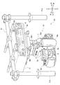
図1は、撮像装置51にハンドル部31を取り付けて手持ち態様とした全体形態を、左後方やや斜め上から見た斜視図である。
撮像装置51は、撮像素子2及びそれを駆動する素子ドライバ3f(図6参照)を備えたカメラ撮像部3と、カメラ撮像部3をジンバル機構で支持するジンバル支持装置21と、ジンバル支持装置21の上方側に取り付けられたカメラ本体部4及びそれが取り付けられた本体支持部11と、を備えている。
カメラ撮像部3には、後述するレンズマウント3aにより複数種のレンズを交換可能に装着することができる。図1〜図4では、例えばアイリス及びフォーカスの外部制御が可能な単焦点のレンズ1が装着された状態が示されている。
撮像装置51を手持ち態様とする場合、図1に示されるように、本体支持部11の上方側に、複数のパイプ状部材が組み合わされてなるハンドル部31を取り付ける。
FIG. 1 is a perspective view of an overall configuration in which the
The
A plurality of types of lenses can be attached to the
When the
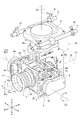
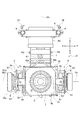
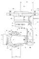
図2〜図4は、撮像装置51からカメラ本体部4及び本体支持部11を除いた、カメラ撮像部3及びジンバル支持装置21を示す図である。
図2は左前方斜め上から見た斜視図であり、図3は前面図であり、図4は左側面図である。
図1〜図4では、カメラ撮像部3及びそれを支持するジンバル支持装置21の基本姿勢が示されている。
この基本姿勢は、レンズ1の光軸CLと回動軸線Cb(後述)とが一致して前後方向に水平に延び、回動軸線Cc(後述)が回動軸線Cbと交わり上下方向に延びる姿勢である。
また、前後左右上下の各方向は、各図に矢印で規定される。撮像装置51の基本姿勢において、上下は天地方向、前は被写体側方向、左はカメラ撮像部3から被写体を見たときの左方に対応する。
2 to 4 are diagrams illustrating the
2 is a perspective view seen from diagonally above the left front, FIG. 3 is a front view, and FIG. 4 is a left side view.
1-4, the basic attitude | position of the
This basic attitude is such that the optical axis CL of the
Also, the front, rear, left and right directions are defined by arrows in each figure. In the basic posture of the
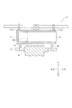
図5は、ハンドル部31を取り付けた状態での、撮像装置51の基本姿勢における上方部分を、光軸CLを含む鉛直面に対しやや右方にて平行な面で切断した模式的断面図である。
FIG. 5 is a schematic cross-sectional view in which the upper part in the basic posture of the
カメラ撮像部3は、レンズ1と、レンズ1による結像を電気信号に変換するCMOSやCCDなどの撮像素子2と、撮像素子2を収容すると共にレンズ1を着脱可能に取り付けるためのレンズマウント3aが設けられた筐体3bと、を有している。
筐体3bの前面には、撮影時に点灯するタリーランプ3cが設けられている。
レンズマウント3aは、レンズ1と互換性のある他のレンズを交換可能に取り付けることができる共通マウントである。
筐体3bの後面側からは、後述するカメラ本体部4との間を電気接続して信号の授受をするための中継ケーブル41(図3,図4,及び図6参照)が引き出されている。
The
A
The
A relay cable 41 (see FIGS. 3, 4, and 6) is provided from the rear surface side of the
ジンバル支持装置21は、撮像部ブラケット6及び支柱フレーム7と、モータMa,Mb,Mcと、を含むジンバル機構JKを有している。
The
カメラ撮像部3には、筐体3bの左右上下側を囲む矩形枠状のブラケット3dが取り付けられている。
ブラケット3dの左右両側にはそれぞれプレート部5が配置されている。
プレート部5は、上下前後方向に平板状に延在するプレート5aと、プレート5aから筐体3b側に突出して設けられた上下方向に延びるガイド柱5bと、を有している。
ブラケット3dには、このガイド柱5bに対して上下移動自在に係合するガイド腕3e(図3)が設けられている。ガイド腕3eは、ガイド柱5bに対し、セットスクリュ3e1を締め付けることで上下方向の任意位置で固定できるようになっている。
The
The
The
プレート部5,ブラケット3d,及び筐体3bは一体化され、その左右側面及び後面を覆うように、コ字状の撮像部ブラケット6が配置されている。
そして、プレート部5のプレート5aの外面側が、撮像部ブラケット6に対して、左右方向に延びる回動軸線Caまわり(矢印Ra)に回動自在となるよう支持されている。
The
The outer surface side of the
撮像部ブラケット6における右方部位には、モータMaが取り付けられており、モータMaの回転軸線Ma1は、回動軸線Caと一致させてある。
これにより、モータMaが駆動されると、その回転方向に応じた回動方向で、カメラ撮像部3は、プレート部5及びブラケット3dと共に、回動軸線Caまわりに回動するようになっている。
この回動で、光軸CLは、回動軸線Caまわりの図1の矢印RLa方向に回動する。
A motor Ma is attached to the right part of the
Accordingly, when the motor Ma is driven, the
With this rotation, the optical axis CL rotates in the direction of the arrow RLa in FIG. 1 around the rotation axis Ca.
ジンバル支持装置21は、上下方向に延在する支柱フレーム7を有している。支柱フレーム7における下部には、モータMbが取り付けられている。
このモータMbの出力軸に、コ字状の撮像部ブラケット6の後部6aが連結されている。
これにより、モータMbが駆動されると、その回転方向に応じた回動方向で、撮像部ブラケット6とそれに支持されたカメラ撮像部3とは、モータMbの出力軸の軸線である回動軸線Cbまわり(矢印Rb)に回動するようになっている。
この回動により、カメラ撮像部3で撮像された画像は、図1に示されるように光軸CLまわり(矢印RLb)に回動する。
The
A
Thus, when the motor Mb is driven, the
By this rotation, the image captured by the
支柱フレーム7の上端部は、上下方向に延びる回動軸線Ccまわりに回転するモータMcの出力軸に連結されている。
これにより、モータMcが駆動されると、その回転方向に応じた回動方向で、支柱フレーム7,支柱フレーム7に連結された撮像部ブラケット6,及び撮像部ブラケット6にプレート部5を介して支持されているカメラ撮像部3が、回動軸線Ccまわり(矢印Rc)に回動するようになっている。
この回動により、光軸CLは、回動軸線Ccまわりの図1の矢印RLc方向に回動する。
The upper end portion of the
Thus, when the motor Mc is driven, the
By this rotation, the optical axis CL rotates in the direction of the arrow RLc in FIG. 1 around the rotation axis Cc.
モータMcは、その上部側に配置されたベース部8に固定されている。
ベース部8は、矩形板状に形成され、左右側面それぞれに前後方向に延在するバー9が取り付けられている。
バー9には、他部材と連結するための複数の連結ブラケット10が取り付けられている。
The motor Mc is fixed to a
The
A plurality of connecting
図1及び図5に示されるように、連結ブラケット10には、カメラ本体部4を支持する本体支持部11が取り付けられている。
本体支持部11は、後方側が解放された上下に薄い扁平の箱状を呈して形成されている。この形状は、カメラ本体部4の外形形状に概ね対応している。
本体支持部11の内部には、後方側から挿抜可能に、カメラ本体部4が装着されている。カメラ本体部4は、左右両端側において、止めねじN4により本体支持部11に締結されている。カメラ本体部4の前方部位には、図5に示されるようにバッテリBAが着脱自在に取り付けられている。
また、本体支持部11の天板部11aには、他の部材に取り付けるための雌ねじや小さいブラケット等を有する連結部11a1が設けられている。
As shown in FIGS. 1 and 5, the
The main
The
Further, the top plate portion 11a of the main
上述のように、撮像装置51は、カメラ撮像部3,ジンバル支持装置21,カメラ本体部4,及び本体支持部11を有して構成されている。
また、ジンバル支持装置21は、撮像装置51の使用状態で、カメラ本体部4を支持した本体支持部11の下方側に位置している。
撮像装置51を空撮に用いる場合は、ヘリコプタ側の部材に対し、天板部11aの連結部11a1を介して取り付ける。
また、撮像装置51で手持ち撮影をする場合は、図1に示されるように、天板部11aの連結部11a1を介してハンドル部31を取り付ける。
ハンドル部31は、手で把持するグリップバー31aを左右に一対備え、複数のパイプ部材が互いに組み付け位置を調整可能に組み合わされてなる把持具である。
As described above, the
In addition, the
When the
Further, when hand-held shooting is performed with the
The
ジンバル支持装置21は、それに取り付けたカメラ撮像部3の空間位置を、上下方向,前後方向,及び左右方向に所定範囲で調整可能とされている。
この調整の内、上下方向の調整については、上述のように、ガイド柱5bに対するガイド腕3eの位置調整で行われる。この調整は、カメラチルト重心調整(その1)と称する。
The
Among the adjustments, the vertical adjustment is performed by adjusting the position of the
前後方向の調整については、2ヶ所で調整可能とされている。
具体的には、まず、図4に示されるように、プレート5aに設けられた前後方向に延びる長孔5a1に挿通されて、プレート5aとガイド柱5bとを締結する止めねじN1の位置を調整することで可能である。この調整は、カメラチルト重心調整(その2)と称する。
また、支柱フレーム7の側板7aに設けられた前後方向に延びる長孔7a1に挿通されて、側板7aとモータMcの出力軸側部材とを締結する止めねじN2の位置を調整することで可能である。この調整は、ジンバルパン調整と称する。
About the adjustment in the front-rear direction, it can be adjusted in two places.
Specifically, as shown in FIG. 4, first, the position of a set screw N1 that is inserted through a long hole 5a1 provided in the
Further, it is possible by adjusting the position of a set screw N2 that is inserted into a long hole 7a1 provided in the
左右方向の調整については、図2に示されるように、撮像部ブラケット6の後部6aに設けられた左右方向に延びる長孔6a1に挿通されて、後部6aとモータMbの出力軸側部材とを締結する止めねじN3の位置を調節することで可能である。この調整は、カメラロール重心調整と称する。
Regarding the adjustment in the left-right direction, as shown in FIG. 2, the
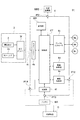
次に、撮像装置51の電気系構成を、ブロック図である図6を参照して説明する。撮像装置51の電気系構成は、これに限定されるものではなく、適宜変形は可能である。
撮像装置51では、従来のいわゆるビデオカメラに相当する部分が一体ではなく、複数の別体に分体化されている。この例では、カメラ撮像部3とカメラ本体部4とに分体化されている。
Next, the electrical system configuration of the
In the
図6に示されるように、カメラ撮像部3は、撮像素子2及び撮像素子2を駆動させるための素子ドライバ3fを有している。素子ドライバ3fは、分体が可能な最小単位で構成される。
タリーランプ3cは例えば素子ドライバ3fに接続され、カメラ本体部4側からの指示により点灯される。
レンズ1による光学像は、撮像素子2により画像信号に変換され、その画像信号は素子ドライバ3fで増幅等の前処理が施されたのち、カメラ本体部4に向け中継ケーブル41を介して出力される。
As shown in FIG. 6, the
The
The optical image by the
カメラ本体部4は、上下に薄い扁平の直方体形状に形成され、内部に制御部CT,カメラコントローラ4b,記憶部MR,ジンバルコントローラ4c,信号処理部4d,画像伝送部4e,及び電源部4fが収容されている。
制御部CTは、撮像装置51の全体の動作を制御する。
カメラコントローラ4bは、撮像素子2の動作、並びに、レンズ1のアイリス及びフォーカスを調整動作させる信号を送出する。また、タリーランプ3cに対して点灯指示を出す。
ジンバルコントローラ4cは、制御部CTの制御の下、モータMa,Mb,Mcに対し、動作指示を出す。また、モータMa,Mb,Mcから入来した回転に関するフィードバック情報を、制御部CTに向け送出する。
信号処理部4dは、制御部CTの制御の下、カメラ撮像部3から入来した画像信号に対し、所望の処理を施す。
記憶部MRは、内蔵のメモリであり、制御部CTの制御の下、画像や撮影情報を記憶する。また、メモリーカード等の外部記憶部MR2を着脱自在とするソケットPT1を有し、装着された外部記憶部MR2に対しても同様の処理が行えるようになっている。
記憶部MR及び外部記憶部MR2は、制御部CTからの要求に応じて記録した画像や撮影情報を再生し出力する。
画像伝送部4eは、制御部CTの制御の下、記憶部MR又は外部記憶部MR2からの再生画像,撮影情報,又は信号処理部4dにより処理された画像等をポートPT2から外部機器Dなどに出力する。
電源部4fは、着脱自在に装着されたバッテリBAからの電力をポートPT3から受けてカメラ撮像部3を含めた撮像装置51全体に供給すると共に、バッテリBAの電力残量を監視し、その残量情報を制御部CTに向け送出する。
The
The control unit CT controls the overall operation of the
The
The
The
The storage unit MR is a built-in memory, and stores images and photographing information under the control of the control unit CT. Further, the socket PT1 that allows the external storage unit MR2 such as a memory card to be freely attached and detached is provided so that the same processing can be performed on the mounted external storage unit MR2.
The storage unit MR and the external storage unit MR2 reproduce and output recorded images and photographing information in response to a request from the control unit CT.
The
The
また、ポートPT4からは、外部機器Dからの動作指示が入来する。この動作指示は、例えば、レンズ1のフォーカス及びアイリスなどの動作,撮像される画像の視軸となる光軸CLの向きを制御するためのモータMa,Mb,Mcの各動作,及び撮像された画像の画像処理に関する指示である。
制御部CTは、この外部からの動作指示に応じて、撮像装置51の動作を制御する。
Further, an operation instruction from the external device D comes from the port PT4. This operation instruction includes, for example, operations of the focus and iris of the
The control unit CT controls the operation of the
ポートPT2及びポートPT4は、外部へ接続する外部ケーブル43に接続される。外部ケーブル43は、例えばヘリコプタによる空中撮影の場合は、ヘリコプタに搭載された無線通信部に接続され、信号は、無線通信部を介して操縦者側の制御装置(外部機器D)と無線で授受される。
また、撮影者の手持ち撮影の場合は、撮影者側の制御装置(外部機器D)に接続され、信号は有線で授受される。もちろん、この場合も無線通信装置を介して無線で授受してもよい。
The ports PT2 and PT4 are connected to an external cable 43 that is connected to the outside. For example, in the case of aerial shooting using a helicopter, the external cable 43 is connected to a wireless communication unit mounted on the helicopter, and signals are transmitted and received wirelessly to the control device (external device D) on the pilot side via the wireless communication unit. Is done.
In the case of hand-held shooting by the photographer, the camera is connected to a control device (external device D) on the photographer side, and signals are exchanged by wire. Of course, in this case as well, data may be exchanged wirelessly via a wireless communication device.
カメラ本体部4の後面側の操作パネル4gには、使用者が操作するための操作系(釦やスイッチ),外部記憶部MR2を装着するためのソケットPT1,及び外部機器へ信号を出力するためのケーブル用ソケットが配置されている。
カメラ撮像部3からの中継ケーブル41及びモータMa,Mb,Mcからの接続ケーブル42a〜42cを接続するソケット群は、カメラ本体部4の後面(操作パネル4g)以外の面に設けられている。
The
A socket group for connecting the
カメラ撮像部3からの中継ケーブル41及びモータMa,Mbからの接続ケーブル42a,42b(図4参照)は、回動軸線Ca〜Ccまわりに回動動作によって重心Gの位置がジンバル動作に影響を及ぼす程には変わらないよう、軽量の線が選択され、引き回されている。
例えば、モータMbを中空モータとし、カメラ撮像部3とカメラ本体部4とをつなぐ中継ケーブル41をその中空の軸部内に挿通することは、回動軸線Cbまわりの回動による重心移動が実質的に生じないので好ましい。
The
For example, if the motor Mb is a hollow motor and the
撮像装置51を使用する場合には、上述したカメラ撮像部3の空間位置調整によって、回動軸線Ca,回動軸線Cb,及び回動軸線Ccを一点で交差させると共に、その一点と、モータMcで回動される全部材の重心Gの位置とを一致させておく。
これにより、カメラ撮像部3及びジンバル支持装置21を各回動軸線Ca,Cb,Ccまわりに回動させても、重心Gの位置が移動せず、極低負荷で滑らかな回動が実現する。
When the
Thereby, even if the
カメラ撮像部3の姿勢は、例えば、カメラ撮像部3と一体的に姿勢センサ(図示せず)を設けておき、その姿勢センサからの検出信号に基づいて制御部CTがカメラ撮像部3の姿勢を判定し、その姿勢が所望の姿勢となるよう各モータMa〜Mcを駆動するなどして制御される。所望の姿勢は、予め記憶部MRや外部記憶部MR2に記憶させておき、制御部CTが参照して得る、或いは外部機器Dを介して使用者側から制御部CTに対して指示されるようにする。
ジンバル支持装置21を用い、上述した重心Gの位置調整をしておくことで、カメラ撮像部3の回動動作が極低負荷で実行できる。そのため、カメラ撮像部3の姿勢制御が高精度かつ高速に実行できる。
For the posture of the
By using the
撮像装置51及びハンドル部31は、軽量であって、ある程度の剛性が確保できる材料で形成される。特に、モータMcで回動させる部分の部材は、より軽量であることが望まれる。その部材は、具体的には、筐体3b,プレート5a,ガイド柱5b,撮像部ブラケット6,支柱フレーム7である。
好適な材料は繊維強化樹脂であり、炭素繊維強化樹脂はより好適である。
The
A preferred material is a fiber reinforced resin, and a carbon fiber reinforced resin is more preferred.
以上詳述した撮像装置51は、従来のビデオカメラに相当する部分を、カメラ撮像部3とカメラ本体部4とに分体化し、レンズ以外のカメラ撮像部3を必要最小限の構成(撮像素子2及び素子ドライバ3fのみ)にして軽量化及びコンパクト化を図っている。特に、電源となるバッテリBAがジンバル支持装置21の可動系(モータMcにより回動される部材群)から除外されて、可動系外に配置されているので、カメラ撮像部3は顕著に軽量化される。
In the
従って、軽量化に関して、カメラ撮像部3を支持するジンバル支持装置21は、従来よりも低剛性で済むので、コンパクトに、また軽量に形成することができる。
Accordingly, regarding the weight reduction, the
また、コンパクト化に関して、特に図4から明らかなように、筐体3bの前後方向となる奥行寸法Laが極めて短くなっている。
これにより、図4に示される、ジンバル支持装置21の支柱フレーム7における回動軸線Ccに対する後方突出距離Lbを、従来よりも短くすることができる。
そのため、撮像装置51は、外観形状がよりコンパクトになる。
また、奥行寸法Laが極めて短くなっていることにより、止めねじN1によるカメラチルト重心調整範囲を、より広く確保することができる。
これにより、交換レンズとして従来よりも長さが長い長焦点レンズを交換装着することが可能となる。そのため、撮影領域が拡張し、より幅の広い映像表現が可能となる。
Further, regarding the downsizing, the depth dimension La in the front-rear direction of the
Thereby, the backward protrusion distance Lb with respect to the rotation axis Cc in the
Therefore, the external appearance of the
In addition, since the depth dimension La is extremely short, a wider range of camera tilt centroid adjustment by the set screw N1 can be secured.
As a result, it is possible to exchange and attach a long focal length lens that is longer than the conventional one as an interchangeable lens. For this reason, the shooting area is expanded, and a wider video expression is possible.
ジンバル支持装置21が軽量かつコンパクトになることで、その分、撮像装置51全体の質量が減少する。そのため、撮像装置51を手持ちで撮影する場合の撮影者の負担が軽減する。
Since the
本発明の実施例は、上述した構成に限定されるものではなく、本発明の要旨を逸脱しない範囲において変形例としてもよい。
撮像装置51の撮影用途は、上述の空中撮影や手持ち撮影の用途に限定されない。
カメラ撮像部3とカメラ本体部4とは、有線の中継ケーブル41で接続されるものに限定されない。両者に無線通信手段を備えて、無線で通信するようにしてもよい。
この場合、カメラ撮像部3には電源となるバッテリ及び電源回路も独立して備える必要があり質量が増加するので、実施例のように中継ケーブル41を用いて有線で接続し、カメラ撮像部3にカメラ本体部4側から中継ケーブル41を介して電源を供給することが好ましい。
The embodiments of the present invention are not limited to the above-described configuration, and modifications may be made without departing from the spirit of the present invention.
The shooting application of the
The
In this case, the
1 レンズ
2 撮像素子
3 カメラ撮像部
3a レンズマウント、 3b 筐体、 3c タリーランプ
3d ブラケット、 3e ガイド腕、 3e1 セットスクリュ
3f 素子ドライバ
4 カメラ本体部
4b カメラコントローラ、 4c ジンバルコントローラ
4d 信号処理部、 4e 画像伝送部、 4f 電源部
4g 操作パネル
5 プレート部
5a プレート、 5a1 長孔、 5b ガイド柱
6 撮像部ブラケット
6a 後部、 6a1 長孔
7 支柱フレーム
7a 側板、 7a1 長孔
8 ベース部
9 バー
10 連結ブラケット
11 本体支持部
11a 天板部、 11a1 連結部
21 ジンバル支持装置
31 ハンドル部、 31a グリップバー
41 中継ケーブル、 42a〜42c 接続ケーブル
43 外部ケーブル
51 撮像装置
BA バッテリ
Ca,Cb,Cc 回動軸線、 CL 光軸
CT 制御部
D 外部機器
G 重心
Ma,Mb,Mc モータ、 Ma1 回転軸線
MR 記憶部、 MR2 外部記憶部
La 奥行寸法、 Lb 後方突出距離
N1〜N4 止めねじ
PT1 ソケット、 PT2,PT3,PT4 ポート
DESCRIPTION OF
Claims (5)
前記撮像素子から出力された画像信号を処理する信号処理部を有し前記カメラ撮像部とは別体のカメラ本体部と、
ジンバル機構を有し、前記カメラ撮像部と前記カメラ本体部との内の前記カメラ撮像部のみを前記ジンバル機構で支持するジンバル支持装置と、
を備えた撮像装置。 A camera imaging unit having an imaging element and a driver for driving the imaging element;
A signal processing unit that processes an image signal output from the imaging device, and a camera body unit separate from the camera imaging unit;
A gimbal support device that has a gimbal mechanism and supports only the camera imaging unit of the camera imaging unit and the camera body unit by the gimbal mechanism;
An imaging apparatus comprising:
前記カメラ撮像部を駆動する電源が前記カメラ本体部側から前記ケーブルを介して供給されることを特徴とする請求項1記載の撮像装置。 A cable for electrically connecting the camera imaging unit and the camera body unit;
The imaging apparatus according to claim 1, wherein power for driving the camera imaging unit is supplied from the camera body side through the cable.
使用状態で、前記ジンバル支持装置が前記本体支持部に対する下方側に位置していることを特徴とする請求項1〜4のいずれか1項に記載の撮像装置。 A main body support for supporting the camera main body;
5. The imaging apparatus according to claim 1, wherein the gimbal support device is positioned on a lower side with respect to the main body support portion in a use state.
Priority Applications (1)
| Application Number | Priority Date | Filing Date | Title |
|---|---|---|---|
| JP2014138593A JP6287648B2 (en) | 2014-07-04 | 2014-07-04 | An imaging device capable of handheld shooting |
Applications Claiming Priority (1)
| Application Number | Priority Date | Filing Date | Title |
|---|---|---|---|
| JP2014138593A JP6287648B2 (en) | 2014-07-04 | 2014-07-04 | An imaging device capable of handheld shooting |
Publications (2)
| Publication Number | Publication Date |
|---|---|
| JP2016017993A true JP2016017993A (en) | 2016-02-01 |
| JP6287648B2 JP6287648B2 (en) | 2018-03-07 |
Family
ID=55233273
Family Applications (1)
| Application Number | Title | Priority Date | Filing Date |
|---|---|---|---|
| JP2014138593A Active JP6287648B2 (en) | 2014-07-04 | 2014-07-04 | An imaging device capable of handheld shooting |
Country Status (1)
| Country | Link |
|---|---|
| JP (1) | JP6287648B2 (en) |
Cited By (7)
| Publication number | Priority date | Publication date | Assignee | Title |
|---|---|---|---|---|
| JP2017125609A (en) * | 2017-01-04 | 2017-07-20 | エスゼット ディージェイアイ テクノロジー カンパニー リミテッドSz Dji Technology Co.,Ltd | platform |
| JP2018056636A (en) * | 2016-09-26 | 2018-04-05 | キヤノン株式会社 | Imaging apparatus and control method thereof, as well as program |
| JP6384002B1 (en) * | 2017-07-21 | 2018-09-05 | エスゼット ディージェイアイ テクノロジー カンパニー リミテッドSz Dji Technology Co.,Ltd | Control device, support system, imaging system, control method, and program |
| JP2019045690A (en) * | 2017-09-01 | 2019-03-22 | 株式会社ユタカ電子製作所 | Gimbal device |
| JP2019518399A (en) * | 2017-04-11 | 2019-06-27 | グイリン ジーシェン インフォメーション テクノロジー カンパニー リミテッドGuilin Zhishen Information Technology Co., Ltd. | Plastic motor for portable stabilizer |
| JP2019186779A (en) * | 2018-04-12 | 2019-10-24 | エスゼット ディージェイアイ テクノロジー カンパニー リミテッドSz Dji Technology Co.,Ltd | Control device, control method, and program |
| JP2021027371A (en) * | 2019-07-31 | 2021-02-22 | キヤノン株式会社 | Universal head device and universal head system comprising the same |
Citations (4)
| Publication number | Priority date | Publication date | Assignee | Title |
|---|---|---|---|---|
| JP2001235793A (en) * | 2000-02-22 | 2001-08-31 | Diamond Air Service Kk | Triaxial drive photographing device |
| JP2011137713A (en) * | 2009-12-28 | 2011-07-14 | Toshiba Corp | Gimbal mechanism |
| CN103672340A (en) * | 2013-12-05 | 2014-03-26 | 张锦海 | Handheld three-shaft shooting pan and tilt head |
| JP2014096800A (en) * | 2009-10-16 | 2014-05-22 | Axis Ab | Pt camera |
-
2014
- 2014-07-04 JP JP2014138593A patent/JP6287648B2/en active Active
Patent Citations (4)
| Publication number | Priority date | Publication date | Assignee | Title |
|---|---|---|---|---|
| JP2001235793A (en) * | 2000-02-22 | 2001-08-31 | Diamond Air Service Kk | Triaxial drive photographing device |
| JP2014096800A (en) * | 2009-10-16 | 2014-05-22 | Axis Ab | Pt camera |
| JP2011137713A (en) * | 2009-12-28 | 2011-07-14 | Toshiba Corp | Gimbal mechanism |
| CN103672340A (en) * | 2013-12-05 | 2014-03-26 | 张锦海 | Handheld three-shaft shooting pan and tilt head |
Cited By (12)
| Publication number | Priority date | Publication date | Assignee | Title |
|---|---|---|---|---|
| JP2018056636A (en) * | 2016-09-26 | 2018-04-05 | キヤノン株式会社 | Imaging apparatus and control method thereof, as well as program |
| JP2017125609A (en) * | 2017-01-04 | 2017-07-20 | エスゼット ディージェイアイ テクノロジー カンパニー リミテッドSz Dji Technology Co.,Ltd | platform |
| JP2019518399A (en) * | 2017-04-11 | 2019-06-27 | グイリン ジーシェン インフォメーション テクノロジー カンパニー リミテッドGuilin Zhishen Information Technology Co., Ltd. | Plastic motor for portable stabilizer |
| US11218047B2 (en) | 2017-04-11 | 2022-01-04 | Guilin Zhishen Information Technology Co., Ltd. | Plastic motor for handheld stabilizer |
| JP6384002B1 (en) * | 2017-07-21 | 2018-09-05 | エスゼット ディージェイアイ テクノロジー カンパニー リミテッドSz Dji Technology Co.,Ltd | Control device, support system, imaging system, control method, and program |
| JP2019022201A (en) * | 2017-07-21 | 2019-02-07 | エスゼット ディージェイアイ テクノロジー カンパニー リミテッドSz Dji Technology Co.,Ltd | Control device, support system, imaging system, control method, and program |
| US11516401B2 (en) | 2017-07-21 | 2022-11-29 | SZ DJI Technology Co., Ltd. | Control device, support system, camera system, and control method and program |
| JP2019045690A (en) * | 2017-09-01 | 2019-03-22 | 株式会社ユタカ電子製作所 | Gimbal device |
| JP2019186779A (en) * | 2018-04-12 | 2019-10-24 | エスゼット ディージェイアイ テクノロジー カンパニー リミテッドSz Dji Technology Co.,Ltd | Control device, control method, and program |
| US11226544B2 (en) | 2018-04-12 | 2022-01-18 | SZ DJI Technology Co., Ltd. | Control device, control method and program |
| JP2021027371A (en) * | 2019-07-31 | 2021-02-22 | キヤノン株式会社 | Universal head device and universal head system comprising the same |
| JP7277305B2 (en) | 2019-07-31 | 2023-05-18 | キヤノン株式会社 | Camera platform device and camera platform system including the same |
Also Published As
| Publication number | Publication date |
|---|---|
| JP6287648B2 (en) | 2018-03-07 |
Similar Documents
| Publication | Publication Date | Title |
|---|---|---|
| JP6287648B2 (en) | An imaging device capable of handheld shooting | |
| JP6692462B2 (en) | Handheld stabilizer | |
| JP5566297B2 (en) | Camera holding module and relief (stereoscopic image) imaging device | |
| JP2018534490A (en) | Stabilizer to stabilize the load | |
| US20170302852A1 (en) | Three Axis Gimbals Stabilized Action Camera Lens Unit | |
| US10288988B2 (en) | Apparatus and method for stabilizing virtual reality camera configurations | |
| US6757011B1 (en) | Vibration isolator for TV camera | |
| WO2018023328A1 (en) | Cradle head and unmanned aerial vehicle | |
| KR20180024752A (en) | Stick for taking a self picture | |
| KR20140131641A (en) | Action Cam mounted using Bluetooth | |
| US11852959B2 (en) | Camera stabilization system | |
| US11543738B2 (en) | Camera stabilization system | |
| WO2019205125A1 (en) | Stability augmentation apparatus and handheld pan tilt apparatus | |
| KR101907895B1 (en) | Stick for taking a self picture | |
| WO2021102738A1 (en) | Gimbal assembly having camera body integrated, and photographing device | |
| CN211176005U (en) | Cloud platform subassembly and shooting equipment of integrated camera fuselage | |
| CN210578844U (en) | Photographing apparatus | |
| CN110740248A (en) | Photographic accessory bearing device with automatic positioning and stable control functions | |
| WO2020000679A1 (en) | Parameter adjustment apparatus and pan-tilt device having same | |
| JP2020071477A (en) | Universal head system | |
| JP2019128448A (en) | Optical unit with tremor correction function | |
| CN210725068U (en) | Intelligent photographing system | |
| CN111684530B (en) | Stabilized camera system | |
| KR102095099B1 (en) | Smart phone tripod with joystick | |
| WO2017149488A1 (en) | Gyrostabilized head for immersive motion picture filming |
Legal Events
| Date | Code | Title | Description |
|---|---|---|---|
| A621 | Written request for application examination |
Free format text: JAPANESE INTERMEDIATE CODE: A621 Effective date: 20160929 |
|
| A977 | Report on retrieval |
Free format text: JAPANESE INTERMEDIATE CODE: A971007 Effective date: 20170517 |
|
| A131 | Notification of reasons for refusal |
Free format text: JAPANESE INTERMEDIATE CODE: A131 Effective date: 20170606 |
|
| A521 | Request for written amendment filed |
Free format text: JAPANESE INTERMEDIATE CODE: A523 Effective date: 20170728 |
|
| TRDD | Decision of grant or rejection written | ||
| A01 | Written decision to grant a patent or to grant a registration (utility model) |
Free format text: JAPANESE INTERMEDIATE CODE: A01 Effective date: 20180109 |
|
| A61 | First payment of annual fees (during grant procedure) |
Free format text: JAPANESE INTERMEDIATE CODE: A61 Effective date: 20180122 |
|
| R150 | Certificate of patent or registration of utility model |
Ref document number: 6287648 Country of ref document: JP Free format text: JAPANESE INTERMEDIATE CODE: R150 |