JP2016002381A - Imaging apparatus and imaging method - Google Patents
Imaging apparatus and imaging method Download PDFInfo
- Publication number
- JP2016002381A JP2016002381A JP2014125733A JP2014125733A JP2016002381A JP 2016002381 A JP2016002381 A JP 2016002381A JP 2014125733 A JP2014125733 A JP 2014125733A JP 2014125733 A JP2014125733 A JP 2014125733A JP 2016002381 A JP2016002381 A JP 2016002381A
- Authority
- JP
- Japan
- Prior art keywords
- light
- polarization
- optical path
- optical
- phase difference
- Prior art date
- Legal status (The legal status is an assumption and is not a legal conclusion. Google has not performed a legal analysis and makes no representation as to the accuracy of the status listed.)
- Pending
Links
Images


Classifications
-
- G—PHYSICS
- G01—MEASURING; TESTING
- G01B—MEASURING LENGTH, THICKNESS OR SIMILAR LINEAR DIMENSIONS; MEASURING ANGLES; MEASURING AREAS; MEASURING IRREGULARITIES OF SURFACES OR CONTOURS
- G01B9/00—Measuring instruments characterised by the use of optical techniques
- G01B9/02—Interferometers
- G01B9/02001—Interferometers characterised by controlling or generating intrinsic radiation properties
- G01B9/02011—Interferometers characterised by controlling or generating intrinsic radiation properties using temporal polarization variation
-
- A—HUMAN NECESSITIES
- A61—MEDICAL OR VETERINARY SCIENCE; HYGIENE
- A61B—DIAGNOSIS; SURGERY; IDENTIFICATION
- A61B3/00—Apparatus for testing the eyes; Instruments for examining the eyes
- A61B3/10—Objective types, i.e. instruments for examining the eyes independent of the patients' perceptions or reactions
- A61B3/102—Objective types, i.e. instruments for examining the eyes independent of the patients' perceptions or reactions for optical coherence tomography [OCT]
-
- A—HUMAN NECESSITIES
- A61—MEDICAL OR VETERINARY SCIENCE; HYGIENE
- A61B—DIAGNOSIS; SURGERY; IDENTIFICATION
- A61B5/00—Measuring for diagnostic purposes; Identification of persons
- A61B5/0059—Measuring for diagnostic purposes; Identification of persons using light, e.g. diagnosis by transillumination, diascopy, fluorescence
- A61B5/0062—Arrangements for scanning
- A61B5/0066—Optical coherence imaging
-
- G—PHYSICS
- G01—MEASURING; TESTING
- G01B—MEASURING LENGTH, THICKNESS OR SIMILAR LINEAR DIMENSIONS; MEASURING ANGLES; MEASURING AREAS; MEASURING IRREGULARITIES OF SURFACES OR CONTOURS
- G01B9/00—Measuring instruments characterised by the use of optical techniques
- G01B9/02—Interferometers
- G01B9/02055—Reduction or prevention of errors; Testing; Calibration
- G01B9/02056—Passive reduction of errors
- G01B9/02058—Passive reduction of errors by particular optical compensation or alignment elements, e.g. dispersion compensation
-
- G—PHYSICS
- G01—MEASURING; TESTING
- G01B—MEASURING LENGTH, THICKNESS OR SIMILAR LINEAR DIMENSIONS; MEASURING ANGLES; MEASURING AREAS; MEASURING IRREGULARITIES OF SURFACES OR CONTOURS
- G01B9/00—Measuring instruments characterised by the use of optical techniques
- G01B9/02—Interferometers
- G01B9/0209—Low-coherence interferometers
- G01B9/02091—Tomographic interferometers, e.g. based on optical coherence
-
- G—PHYSICS
- G01—MEASURING; TESTING
- G01B—MEASURING LENGTH, THICKNESS OR SIMILAR LINEAR DIMENSIONS; MEASURING ANGLES; MEASURING AREAS; MEASURING IRREGULARITIES OF SURFACES OR CONTOURS
- G01B2290/00—Aspects of interferometers not specifically covered by any group under G01B9/02
- G01B2290/70—Using polarization in the interferometer
Landscapes
- Health & Medical Sciences (AREA)
- Life Sciences & Earth Sciences (AREA)
- Physics & Mathematics (AREA)
- General Health & Medical Sciences (AREA)
- Nuclear Medicine, Radiotherapy & Molecular Imaging (AREA)
- Radiology & Medical Imaging (AREA)
- General Physics & Mathematics (AREA)
- Molecular Biology (AREA)
- Medical Informatics (AREA)
- Biophysics (AREA)
- Veterinary Medicine (AREA)
- Engineering & Computer Science (AREA)
- Biomedical Technology (AREA)
- Heart & Thoracic Surgery (AREA)
- Public Health (AREA)
- Animal Behavior & Ethology (AREA)
- Surgery (AREA)
- Chemical & Material Sciences (AREA)
- Dispersion Chemistry (AREA)
- Pathology (AREA)
- Ophthalmology & Optometry (AREA)
- Investigating Or Analysing Materials By Optical Means (AREA)
- Eye Examination Apparatus (AREA)
Abstract
Description
本発明は、偏光成分が異なる複数の光を検出することにより被検査物を撮影する撮影装置及びその方法に関する。 The present invention relates to an imaging apparatus and method for imaging an object to be inspected by detecting a plurality of lights having different polarization components.
近年、低コヒーレンス光による干渉を利用した光断層画像撮像(Optical Coherence Tomography:OCT)装置(以下、OCT装置と記載)が実用化されている。これは、被検査物の断層画像を高分解能で且つ非侵襲に取得することができる。そのため、OCT装置は、特に眼科領域において、被検眼の眼底の断層画像を得るうえで、必要不可欠な装置になりつつある。また、眼科領域以外でも、皮膚の断層観察や、内視鏡やカテーテルとして構成して、消化器、循環器の壁面断層画像撮像等が試みられている。 In recent years, an optical coherence tomography (OCT) apparatus (hereinafter referred to as an OCT apparatus) using interference by low-coherence light has been put into practical use. This makes it possible to acquire a tomographic image of the inspection object with high resolution and non-invasively. For this reason, the OCT apparatus is becoming an indispensable apparatus for obtaining a tomographic image of the fundus of the eye to be examined, particularly in an ophthalmic region. In addition to the ophthalmological region, tomographic observation of the skin, imaging as a wall tomographic image of the digestive organ, circulatory organ, and the like have been attempted as an endoscope or catheter.
ここで、眼科用OCT装置において、眼底組織の形状をイメージングする通常のOCT画像(輝度画像とも言う)に加えて、眼底組織の光学特性や動き等をイメージングする機能OCT画像の取得が試みられている。特に、偏光OCT装置は、機能OCT装置の一つとして開発されており、光の偏光パラメータを利用して信号を取得するものである。偏光OCT装置は、複屈折性を有する神経線維層や偏光を解消する性質を有する網膜層の描出が可能であり、緑内障や加齢黄斑変性などを対象とした研究が進められている。 Here, in the ophthalmic OCT apparatus, in addition to a normal OCT image (also referred to as a luminance image) for imaging the shape of the fundus tissue, an attempt is made to acquire a functional OCT image for imaging optical characteristics and movement of the fundus tissue. Yes. In particular, a polarization OCT apparatus has been developed as one of functional OCT apparatuses, and acquires a signal using a polarization parameter of light. The polarization OCT apparatus can depict a nerve fiber layer having birefringence and a retinal layer having a property of depolarizing polarization, and research on glaucoma and age-related macular degeneration is being conducted.
このとき、偏光OCT装置は、眼底組織の光学特性の一つである偏光パラメータ(リターデーションとオリエンテーション)を用いて偏光OCT画像を構成し、眼底組織の区別やセグメンテーションを行うことができる。一般的に、偏光OCT装置は、波長板(例えば、1/4波長板や1/2波長板)を用いることで、OCT装置の測定光と参照光との偏光状態を所望の偏光状態になるように補正可能な光学系が構成されている。光源から出射される光の偏光状態を所望の偏光状態に補正し、また、試料に照射する測定光の偏光状態を所望の偏光状態に補正した光を用いて、その干渉光を2つの直交する直線偏光として分割して検出して、偏光OCT画像を生成する(非特許文献1)。 At this time, the polarization OCT apparatus can construct a polarization OCT image using a polarization parameter (retardation and orientation) which is one of the optical characteristics of the fundus tissue, and can perform discrimination and segmentation of the fundus tissue. In general, a polarization OCT apparatus uses a wave plate (for example, a quarter wave plate or a half wave plate) to change the polarization state of the measurement light and the reference light of the OCT apparatus to a desired polarization state. Thus, an optical system that can be corrected is configured. Using the light in which the polarization state of the light emitted from the light source is corrected to the desired polarization state, and the polarization state of the measurement light applied to the sample is corrected to the desired polarization state, the interference light is orthogonalized. A polarization OCT image is generated by dividing and detecting as linearly polarized light (Non-Patent Document 1).
ここで、装置の小型化のために、例えば、ミラー等の反射部材を用いて光路を折り曲げる構成が一般的に利用される。このとき、ミラー等の反射面が有する誘電率(複素屈折率)に応じて、反射面で反射した光の異なる偏光成分の間の位相差(位相遅延)が生じるという性質が一般的に知られている。このため、反射部材により、反射面に対するS偏光成分とP偏光成分とにおいて、反射の前後で位相差が生じてしまう。 Here, in order to reduce the size of the apparatus, for example, a configuration in which an optical path is bent using a reflecting member such as a mirror is generally used. At this time, it is generally known that a phase difference (phase delay) occurs between different polarization components of light reflected by the reflecting surface according to the dielectric constant (complex refractive index) of the reflecting surface such as a mirror. ing. For this reason, the reflection member causes a phase difference before and after reflection in the S-polarized component and the P-polarized component with respect to the reflecting surface.
非特許文献1では、マッハツェンダ型の干渉計を有する偏光OCT装置において、参照光が参照ミラーにより直角に反射される。このため、一方の偏光成分が他方の偏光成分に対して位相の遅延が発生し、異なる偏光成分の間の位相差が生じてしまう。 In Non-Patent Document 1, in a polarization OCT apparatus having a Mach-Zehnder interferometer, reference light is reflected at a right angle by a reference mirror. For this reason, the phase of one polarization component is delayed with respect to the other polarization component, resulting in a phase difference between different polarization components.
なお、参照光路に設けられたミラーだけでなく、測定光路に設けられた接眼部等の透過部材において、すなわち、ファイバ等ではなく空気中に配置される光学部材において、このような問題が生じる可能性がある。 Note that such a problem occurs not only in the mirror provided in the reference optical path but also in a transmissive member such as an eyepiece provided in the measurement optical path, that is, in an optical member arranged in the air instead of a fiber or the like. there is a possibility.
ところで、偏光OCT装置は、被検査物で生じる異なる偏光成分の間の位相差を検出することで、偏光OCT画像を取得することができる。しかしながら、偏光OCT装置の光路で偏光の位相差が生じてしまうと、被検査物で生じる異なる偏光成分の間の位相差を精度良く検出することが難しい。 By the way, the polarization OCT apparatus can acquire a polarization OCT image by detecting a phase difference between different polarization components generated in the inspection object. However, if a polarization phase difference occurs in the optical path of the polarization OCT apparatus, it is difficult to accurately detect the phase difference between different polarization components generated in the inspection object.
本発明の目的の一つは、光路に設けられた光学部材の反射や透過により生じる異なる偏光成分の間の位相差(位相遅延)を低減することである。 One of the objects of the present invention is to reduce a phase difference (phase delay) between different polarization components caused by reflection or transmission of an optical member provided in an optical path.
上記の目的を達成するための、本発明の一様態による撮影装置は、
測定光を照射した被検査物からの戻り光と前記測定光に対応する参照光とを合波した光を偏光成分が異なる複数の光に分割する分割手段と、前記複数の光を検出する検出手段と、を有する被検査物を撮影する撮影装置であって、
光路に設けられた光学部材により生じる異なる偏光成分の間の位相差を補正する補正手段を有する。
In order to achieve the above object, a photographing apparatus according to one aspect of the present invention is provided.
Dividing means for dividing the light, which is the combined return light from the object irradiated with the measurement light and the reference light corresponding to the measurement light, into a plurality of lights having different polarization components, and detection for detecting the plurality of lights An imaging device for imaging an object to be inspected,
Correction means for correcting a phase difference between different polarization components generated by an optical member provided in the optical path is provided.
また、上記の目的を達成するための、本発明の一様態による撮影装置は、
測定光を照射した被検査物からの戻り光を偏光成分が異なる複数の光に分割する分割手段と、前記複数の光を検出する検出手段と、を有する被検査物を撮影する撮影装置であって、
光路に設けられた光学部材により生じる異なる偏光成分の間の位相差を補正する補正手段を有する。
In order to achieve the above object, a photographing apparatus according to one aspect of the present invention is provided.
An imaging apparatus for imaging an inspection object, comprising: a dividing unit that divides return light from an inspection object irradiated with measurement light into a plurality of lights having different polarization components; and a detection unit that detects the plurality of lights. And
Correction means for correcting a phase difference between different polarization components generated by an optical member provided in the optical path is provided.
本発明によれば、光路に設けられた光学部材により生じる異なる偏光成分の間の位相差を補正することができる。これにより、光路に設けられた光学部材の反射や透過により生じる偏光成分の間の位相差(位相遅延)を低減することができる。 According to the present invention, it is possible to correct a phase difference between different polarization components generated by an optical member provided in an optical path. Thereby, the phase difference (phase delay) between the polarization components produced by reflection and transmission of the optical member provided in the optical path can be reduced.
発明を実施するための形態によれば、光路に設けられた光学部材により生じる異なる偏光成分の間の位相差を補正することができる。これにより、光路に設けられた光学部材の反射や透過により生じる異なる偏光成分の間の位相差(位相遅延)を低減することができる。 According to the embodiment for carrying out the invention, it is possible to correct a phase difference between different polarization components generated by an optical member provided in an optical path. Thereby, the phase difference (phase delay) between different polarization components generated by reflection or transmission of the optical member provided in the optical path can be reduced.
ここで、異なる偏光成分の間の位相差を補正する補正手段は、上記光学部材と同じ種類の光学部材であり、該位相差を補正するように配置されることが好ましい。このとき、光学部材及び補正手段は、例えば、測定光の光路に設けられたダイクロイックミラーや参照光の光路に設けられた参照ミラーである。 Here, the correction means for correcting the phase difference between different polarization components is an optical member of the same type as the optical member, and is preferably arranged so as to correct the phase difference. At this time, the optical member and the correction unit are, for example, a dichroic mirror provided in the optical path of the measurement light or a reference mirror provided in the optical path of the reference light.
また、異なる偏光成分の間の位相差を補正する補正手段は、上記光学部材とは異なる種類の光学部材であり、補正手段を駆動する駆動手段と、該位相差を補正するように該駆動手段を制御する制御手段と、を有することが好ましい。このとき、補正手段は、例えば、偏光調整部材の一例であるλ/2板やλ/4板であり、モータ等の駆動手段は偏光調整部材を回転する。 Further, the correction means for correcting the phase difference between the different polarization components is an optical member of a type different from the optical member, the drive means for driving the correction means, and the drive means for correcting the phase difference. It is preferable to have a control means for controlling. At this time, the correcting means is, for example, a λ / 2 plate or a λ / 4 plate which is an example of a polarization adjusting member, and a driving means such as a motor rotates the polarization adjusting member.
また、補正手段は、例えば、ポラライザ(第3の実施形態を参照)、液晶光学素子(第4の実施形態を参照)、ファイバ型の偏光制御部材(第5の実施形態を参照)である。 The correction means is, for example, a polarizer (see the third embodiment), a liquid crystal optical element (see the fourth embodiment), or a fiber-type polarization control member (see the fifth embodiment).
なお、光学部材が測定光の光路に設けられている場合には補正手段は測定光の光路に設けられることが好ましい。これにより、測定光に対して生じた異なる偏光成分の間の位相差を測定光の光路において補正することができる。また、光学部材が参照光の光路に設けられている場合には補正手段は参照光の光路に設けられることが好ましい。これにより、参照光に対して生じた異なる偏光成分の間の位相差を参照光の光路において補正することができる。これらにより、異なる偏光成分の間の位相差の補正をシンプルに構成することができる。 In addition, when the optical member is provided in the optical path of the measurement light, the correction unit is preferably provided in the optical path of the measurement light. Thereby, the phase difference between the different polarization components generated with respect to the measurement light can be corrected in the optical path of the measurement light. In addition, when the optical member is provided in the optical path of the reference light, the correction unit is preferably provided in the optical path of the reference light. Thereby, the phase difference between different polarization components generated with respect to the reference light can be corrected in the optical path of the reference light. As a result, the correction of the phase difference between the different polarization components can be simply configured.
本発明の一実施形態を、図面を用いて詳細に説明する。 An embodiment of the present invention will be described in detail with reference to the drawings.
(第1の実施形態:光学部材で生じる偏光の位相差を同じ種類の光学部材で補正)
本実施形態における偏光OCT装置の構成について図1から図4を用いて説明する。尚、便宜上、各図に示す通りX、Y、Z軸を設定して説明する。
(First Embodiment: Correcting a phase difference of polarized light generated in an optical member with the same type of optical member)
The configuration of the polarization OCT apparatus in the present embodiment will be described with reference to FIGS. For convenience, the description will be made with the X, Y, and Z axes set as shown in the drawings.
[装置の全体構成]
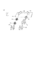
図1は、本実施形態における偏光OCT装置の全体構成の概略図であり、SS(Swept Source)−PS(Polarization sensitive)−OCT装置を、マッハツェンダ型の干渉計による構成例である。
[Overall configuration of the device]
FIG. 1 is a schematic diagram of an overall configuration of a polarization OCT apparatus according to the present embodiment, and is an example of a configuration of an SS (swept source) -PS (polarization sensitive) -OCT apparatus using a Mach-Zehnder interferometer.
<SS−PS−OCT装置100の構成>
SS−PS−OCT装置100の構成について説明する。まず、光源101は、周期的に光の発振波長が変化する波長掃引光源を用いて構成され、例えば、心波長1040nm、バンド幅100nmの光を出射する。光源101から出射された光は、シングルモード(Single Mode)ファイバ(以下SMファイバと記載)102、偏光制御器103を介してコリメータ104に導かれ、コリメータ104においてコリメート光が空間に出射される。出射されたコリメート光は、ポラライザ105を介してビームスプリッタ106に導かれ、測定光(OCT測定光とも言う)と参照光(OCT測定光に対応する参照光とも言う)に分岐される。ビームスプリッタ106の分岐比は、90(参照光):10(測定光)である。尚、分岐比はこれらの値に限定されるものではなく、他の値とすることも可能である。
<Configuration of SS-PS-
The configuration of the SS-PS-
偏光制御器103は、光源101から射出する光の偏光を所望の偏光状態になるように補正する。偏光制御器103は例えばファイバ型の偏光制御器であり、ファイバをコイル状に巻いたパドルを作り、各パドルを傾倒することで偏光を補正するパドル型、ファイバを圧迫、回転させ偏光を補正するインライン型などが挙げられる。また、ファイバから光を空間に出射し、1/2波長板及び1/4波長板を用いて偏光を補正するバルク型でも良い。本実施形態では偏光制御器103で光源101からの光は直線偏光に補正されている。また、光源101の偏光度が高くない場合、図1に示すように、ポラライザ105を配置することで光源101より出射した光の偏光度を上げても良い。その場合、偏光制御器103を調整することで、ポラライザ105の透過光量を調整することも可能である。また、偏光制御器103を配置せず、SMファイバ102にコリメータ104を接続する構成にすることも可能である。この場合、光源101より出射する光の偏光状態の補正は必要なく、偏光度のみを高めることが出来るが、光の偏光状態によっては干渉計に導かれる光量が少なくなってしまう可能性があるため、十分な光量であるか確認する。例えば、光量の確認方法としては、ポラライザ105を通過した後のコリメート光をパワーモニタで測定し、一定の光量以上であるか否かを判定する方法や、検出器133や134で必要十分量の光が検出されているかを判定する方法が挙げられる。
The
(測定光路)
分岐された測定光は、1/4波長板107を通過し、瞳位置において測定光をY方向に走査するY走査用ガルバノスキャナ108とX走査用ガルバノスキャナ109にて反射する。ガルバノスキャナ108、109によって進路を変えた測定光は、更にダイクロイックミラー110、111で反射した後、スキャンレンズ112、対物レンズ113を介して被検眼115に入射する。本実施形態では被検眼115において円偏光となるように1/4波長板107を配置する。また、対物レンズ113はステージ114上に固定されており、光軸方向に動くことで、被検眼の視度調整を行うことが出来る。図示していないが、ガルバノスキャナ108、109とステージ114は駆動制御部によって制御され、被検眼115の所望の範囲(断層画像の取得範囲、断層画像の取得位置、測定光の照射位置とも言う)で測定光を走査することが出来る。測定光は、ステージ114上に乗った対物レンズ113により、被検眼115に入射し、眼底にフォーカスされる。眼底を照射した測定光は各網膜層で反射・散乱し、上述の光学経路を辿りビームスプリッタ106を介してビームスプリッタ122へ入射する。測定光はガルバノスキャナ108においてY−Z平面内で反射し、次にガルバノスキャナ109においてX−Y平面内で反射する。
(Measurement optical path)
The branched measurement light passes through the quarter-
ここで、偏光OCT装置において、一般的なOCT装置と同様に、被検眼115にはOCT測定光以外にも固視灯や眼底像を取得するためのSLOビーム、前眼部観察用の観察光など、多波長の光が入射する場合が考えられる。その場合、測定光路内には波長を選択的に反射・透過するダイクロイックミラーを配置する。そのため、測定光はダイクロイックミラー110、111においても反射し、進路を変える。
Here, in the polarization OCT apparatus, similarly to a general OCT apparatus, in addition to the OCT measurement light, an SLO beam for acquiring a fixation lamp and a fundus image, and observation light for anterior ocular segment observation are applied to the
(参照光路)
一方、ビームスプリッタ106で分岐された参照光は、分散補償ガラス116、NDフィルタ117を介し、コヒーレンスゲートステージ119上のミラー118a、118bで反射される。参照光はNDフィルタ117を介して減衰し、干渉光が検出器の測定レンジを超えない範囲に調整される。コヒーレンスゲートステージ119は、被検者の眼軸長の相違等に対応する為、駆動制御部で制御され、図1においてX方向に動くことで調整を行う。ミラー118a、118bは参照光をX−Z平面内で反射するように配置されている。一方で参照光はY方向に振動する直線偏光であるため、参照光はミラー118a、118bの反射面に対してS偏光成分を持たない。即ち、反射によるS偏光とP偏光の間の位相差は発生せず、偏光状態を一定に保つことが可能である。従って、ミラー118a、118bの反射面に対してS偏光成分のみ、或いはP偏光成分のみの参照光を入射させることで、位相の遅延を抑制することが可能である。
(Reference optical path)
On the other hand, the reference light branched by the
ミラー118a、118bで反射された参照光は、1/4波長板120、1/2波長板121を介してビームスプリッタ122へ入射する。1/2波長板を所定の角度、回転させて配置することにより、1/2波長板を通過した光の振動方向を任意に変化させることが出来る。本実施形態では偏光ビームスプリッタ123、124に入射する参照光の偏光状態が直交する二つの偏光軸に対して互いに45°傾いた直線偏光となるように1/2波長板121を配置する。
The reference light reflected by the
(検出光路)
ビームスプリッタ122に入射した測定光と参照光は合波されて干渉光となり、分岐比50:50で分割される。なお、ビームスプリット122は、なお、偏光成分が異なる複数の光に分割する分割手段の一例である。分割される干渉光は、振幅の位相が互いに反転した干渉光(以下、正の成分および負の成分と表現する)となっており、正の干渉光は偏光ビームスプリッタ123へ導かれ、負の干渉光は偏光ビームスプリッタ124へ導かれる。偏光ビームスプリッタ123、124では直交する二つの偏光軸に合わせて干渉光が分割され、水平(Horizontal)偏光成分(以下、H成分)と、垂直(Vertical)偏光成分(以下、V成分)の二つの光に分割される。偏光ビームスプリッタ123、124で分割された正負それぞれの干渉光のH成分は、受光用コリメータ125、129で受光され、SMファイバ127、131を介して検出器133に入射し、ここで差動検出される。なお、検出器133、134は、偏光成分が異なる複数の光を検出する検出手段の一例である。一方、干渉光のV成分は受光用コリメータ126、130で受光され、SMファイバ128、132を介して検出器134に入射する。検出器133、134でそれぞれ受光した光は、光の強度に応じた電気信号として出力される。
(Detection light path)
The measurement light and the reference light incident on the
なお、本実施形態では、直交する二つの偏光軸に対して参照光を45°の直線偏光とすることで、H成分およびV成分に同等の光が分割される。また、本実施形態では測定光を円偏光としていることにより、被検眼115の眼底の細胞や繊維の方向に関係なく同時に取得することが出来る。結果として、一度で全ての偏光方向についてデータ取得が可能となり、同一箇所について偏光方向ごとに撮影する必要はなく、一度の撮影でデータ取得することが可能である。
In the present embodiment, the reference light is linearly polarized at 45 ° with respect to two orthogonal polarization axes, whereby equivalent light is divided into the H component and the V component. Further, in the present embodiment, the measurement light is circularly polarized, so that the measurement light can be simultaneously acquired regardless of the direction of cells and fibers on the fundus of the
また、本実施形態では光の反射のためにミラーを設置したが、光を反射可能なものであれば何でも良く、例えば直角プリズムなどでも同様の効果を得ることが出来る。 In this embodiment, a mirror is provided for light reflection. However, any mirror can be used as long as it can reflect light. For example, a right angle prism can provide the same effect.
なお、SS−PS−OCTのバルク系の構成例を示したが、これに限定されるものではなく、ファイバ系で構成することも可能である。その場合は、図2に示すように、ポラライザ105、ビームスプリッタ106、122、偏光ビームスプリッタ123、124を、インラインタイプに置き換えることで同様の効果を得ることができる。
In addition, although the structural example of the bulk system of SS-PS-OCT was shown, it is not limited to this, It can also comprise by a fiber system. In that case, as shown in FIG. 2, the same effect can be obtained by replacing the
<SS−PS−OCT装置200の構成>
SS−PS−OCT装置200の構成について、図2を用いて説明する。なお、SS−PS−OCT装置100と同様の構成については、詳細な説明は省略する。
<Configuration of SS-PS-
The configuration of the SS-PS-
SMファイバ102は、コネクタ201を介してポラライザ202と接続する。なお、ポラライザ202以降のファイバは、偏波保持(Polarization Maintaining:PM)ファイバ(以下PMファイバと記載)で構成することで、偏光状態を維持することが可能である。ポラライザ202はコネクタ203を介してビームスプリッタ204と接続し、ビームスプリッタ204は測定光出射用コリメータ205、参照光出射用コリメータ206、コネクタ208とそれぞれ接続する。ビームスプリッタ204の分岐比は、90(参照光):10(測定光)である。尚、分岐比はこれらの値に限定されるものではなく、他の値とすることも可能である。
The
(測定光路)
分岐された測定光は、コリメータ205より出射し、1/4波長板107、ガルバノスキャナ108、109、ダイクロイックミラー110、111、スキャンレンズ112、対物レンズ113を介して被検眼115に入射する。被検眼115を照射した測定光は各網膜層で反射・散乱し、入射時と同様の光学経路を辿りビームスプリッタ204を介してビームスプリッタ209へ入射する。
(Measurement optical path)
The branched measurement light exits from the
(参照光路)
一方、参照光は、コリメータ206より出射し、分散補償ガラス116、NDフィルタ117を介し、コヒーレンスゲートステージ119上のミラー118a、118bで反射し、1/4波長板120、1/2波長板121を介してコリメータ207にて受光し、ビームスプリッタ209へ入射する。
(Reference optical path)
On the other hand, the reference light is emitted from the
(検出光路)
ビームスプリッタ209の分岐比は50:50である。入射端は参照光受光用コリメータ207、コネクタ208と接続し、出射端はコネクタ210、211を介して偏光ビームスプリッタ212、213と接続する。偏光ビームスプリッタ212、213で分岐される干渉光のH成分は検出器133の入力端子へ入力し、一方で干渉光のV成分は検出器134の入力端子へ入力する。
(Detection light path)
The branching ratio of the
以上のように構成することで、バルク系のSS−PS−OCT装置100をファイバ系のSS−PS−OCT装置200へ変更することが可能である。
By configuring as described above, the bulk SS-PS-
(偏光の位相差の補正手段の例:同じ種類のガルバノスキャナによる補正)
このとき、第1の走査手段の一例であるガルバノスキャナ108の反射面に対してS偏光成分の位相が遅延し、同様に第2の走査手段の一例であるガルバノスキャナ109の反射面に対してもS偏光成分の位相が遅延する。ここで、ガルバノスキャナ108に対する測定光の入射面と、ガルバノスキャナ109に対する測定光の入射面は直交関係にある。そのため、ガルバノスキャナ108の反射により位相の遅延が生じる偏光成分と、ガルバノスキャナ109の反射により位相の遅延が生じる偏光成分は逆転し、結果として反射による生じる偏光の位相差は相殺されることになる。
(Example of means for correcting polarization phase difference: correction using the same type of galvano scanner)
At this time, the phase of the S-polarized light component is delayed with respect to the reflection surface of the
(偏光の位相差の補正手段の例:同じ種類のダイクロイックミラーによる補正)
波長選択部材の一例であるダイクロイックミラーの反射・透過で生じる偏光の位相の遅延量は波長に応じて異なるため、信号処理を用いて補正を行うことは困難である。そのため、同じダイクロイックミラーを測定光路内に別途設置し、偏光の位相遅延を相殺するように、反射させる方法が望ましい。具体的には、図4に示すように、測定光を第1の波長選択部材の一例であるダイクロイックミラー110においてX−Y平面401内で反射し、続いて第2の波長選択部材の一例であるダイクロイックミラー111においてY−Z平面402内で反射するようにダイクロイックミラー110、111を配置する。ガルバノスキャナ108、109の時と同様に、ダイクロイックミラー110に対する入射面401とダイクロイックミラー111に対する入射面402が直交関係にあるとき、ダイクロイックミラー110の反射により位相遅延が生じるS偏光成分とダイクロイックミラー111の反射により位相の遅延が生じるS偏光成分も直交関係にある。そのため、2回の反射によって、各反射で生じる位相差を相殺することが可能である。
(Example of means for correcting polarization phase difference: correction using the same type of dichroic mirror)
Since the amount of phase delay of polarized light generated by reflection / transmission of a dichroic mirror, which is an example of a wavelength selection member, varies depending on the wavelength, it is difficult to perform correction using signal processing. Therefore, it is desirable that the same dichroic mirror is separately installed in the measurement optical path and reflected so as to cancel the phase delay of polarized light. Specifically, as shown in FIG. 4, the measurement light is reflected in the
(偏光の位相差の補正手段の例:偏光調整部材の一例である波長板による補正)
ここで、参照光の偏光状態を、反射面に対してS偏光成分ないしP偏光成分のみの直線偏光ではなく、各々の成分を含む偏光とする場合を考える。この場合、ミラー118aやミラー118bの反射により偏光の位相差が生じて、楕円偏光となってしまう可能性がある。
(Example of means for correcting polarization phase difference: correction by a wave plate as an example of a polarization adjusting member)
Here, let us consider a case where the polarization state of the reference light is not linearly polarized light of only the S-polarized component or the P-polarized component with respect to the reflecting surface but is polarized light including each component. In this case, there is a possibility that a phase difference of polarization occurs due to the reflection of the
この場合、反射により楕円偏光となるため、ミラー118bと1/2波長板121の間に1/4波長板120を配置し、直線偏光となるように補正すれば良い。なお、本実施形態では偏光補正のために1/4波長板120を用いる例を記載するが、楕円偏光から直線偏光への補正は1/4波長板120でなくても良い。例えば、ポラライザ、液晶光学素子、電気光学素子、ファイバ型偏光コントローラなど、参照光を直線偏光に補正出来るものであれば何でも良い。
In this case, since it becomes elliptically polarized light by reflection, a
また、1/4波長板120と1/2波長板121との複数の偏光調整部材を光路に設けなくても、いずれか一つの偏光調整部材を用いて、参照光の光路に設けられたミラー118aや118bで生じた偏光の位相差を補正するように構成しても良い。このとき、例えば、1/2波長板121をモータ等の駆動手段により回転するように制御することで、偏光状態を調整するように構成することが好ましい。具体的には、1/2波長板121を用いた偏光状態を調整する構成は、検出器133、134で検出される信号強度が略同一となるように1/2波長板をモータ等の駆動手段により回転させることで行う。このとき、例えば対物レンズ113と被検眼115の間で遮光し、測定光が検出器133、134に戻らないようにすることで、参照光の信号強度のみを検出することが可能となる。但し、検出を差動検出にて行う場合は干渉信号が必要となるため、例えば参照光路中に1mmから数mm厚程度の薄いガラス板を配してファブリペロー干渉系を構築し、多重反射により参照光の干渉信号を生成して差動検出を行う。参照光が正しく補正されているかの確認は、例えば、ビームスプリッタ122の手前に偏光測定器を配し、参照光の偏光状態をモニタすれば良い。
Further, even if a plurality of polarization adjusting members of the
以上説明した構成によれば、光学部材の反射・透過などの影響により偏光の位相差(位相遅延)が生じる場合においても、偏光状態を補正することができるため、被検眼の偏光特性を高精度に測定することが出来る。 According to the configuration described above, since the polarization state can be corrected even when a phase difference (phase delay) of polarization occurs due to the reflection / transmission of the optical member, the polarization characteristic of the eye to be inspected is highly accurate. Can be measured.
(第2の実施形態:光学部材で生じる偏光の位相差を同じ種類の光学部材で補正)
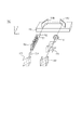
次に、第2の実施形態について図3を用いて説明する。第1の実施形態において、SS−PS−OCTの構成例を示したが、これに限定されるものではなく、スペクトラルドメイン方式のOCT(以下、SD−OCT)でも良い。本実施形態に係るSD−PS−OCTの構成とすることで、光学部材で生じる偏光の位相差(位相遅延)を補正することが可能である。また、第1の実施形態ではマッハツェンダ型の干渉計による構成例を示したが、本実施形態のようにマイケルソン型の干渉計で構成することもできる。
(Second Embodiment: Correcting a phase difference of polarized light generated in an optical member with the same type of optical member)
Next, a second embodiment will be described with reference to FIG. In the first embodiment, the configuration example of SS-PS-OCT has been described. However, the present invention is not limited to this, and Spectral Domain OCT (hereinafter referred to as SD-OCT) may be used. By adopting the configuration of the SD-PS-OCT according to the present embodiment, it is possible to correct the phase difference (phase delay) of the polarization generated in the optical member. In the first embodiment, a configuration example using a Mach-Zehnder interferometer has been described. However, a Michelson interferometer may be used as in the present embodiment.
<SD−PS−OCT装置300の構成>
SD−PS−OCT装置300の構成について図3を用いて説明する。なお、第1の形態に係るSS−PS−OCT装置100と同様の構成については、詳細な説明は省略する。
<Configuration of SD-PS-
The configuration of the SD-PS-
光源301は、低コヒーレント光源であるSLD光源(Super Luminescent Diode)であり、例えば、中心波長850nm、バンド幅50nmの光を出射する。光源101としてSLDを用いたが、ASE光源(Amplified Spontaneous Emission)等、低コヒーレント光が出射できる光源であれば何れでも良い。光源301から出射された光は、SMファイバ102、偏光制御器103を介してコリメータ104に導かれ、コリメータ104においてコリメート光が空間に出射される。出射されたコリメート光は、ポラライザ105を介してビームスプリッタ106に導かれ、測定光と参照光に分岐される。ビームスプリッタ106の分岐比は、90(参照光):10(測定光)である。尚、分岐比はこれらの値に限定されるものではなく、他の値とすることも可能である。
The
(測定光路)
分岐された測定光は、1/4波長板107、ガルバノスキャナ108、109、ダイクロイックミラー110、111、スキャンレンズ112、対物レンズ113を介して被検眼115に入射する。被検眼115を照射した測定光は各網膜層で反射・散乱し、上述の光学経路を辿りビームスプリッタ106を介して偏光ビームスプリッタ305へ入射する。
(Measurement optical path)
The branched measurement light enters the
(参照光路)
一方、分岐された参照光は、1/4波長板302、分散補償ガラス116、NDフィルタ117を介してコヒーレンスゲートステージ304上に設置されたミラー303a、303b、303cにより反射される。コヒーレンスゲートステージ304は、図3においてX方向に動くことで、ゲート位置を調整することが出来る。また、ミラーの配置は必ずしもこれに限らない。例えば、ミラー303aをコヒーレンスゲートステージ304から外し、固定する構成も可能である。この場合、コヒーレンスゲート位置はコヒーレンスゲートステージ304を図3においてZ方向に動かすことで調整可能である。同様に、ミラー303a、303bをコヒーレンスゲートステージ304から外して固定する構成も可能である。この場合、コヒーレンスゲート位置はコヒーレンスゲートステージ304を図3においてY方向に動かすことで調整可能である。また、1/4波長板302は、偏光ビームスプリッタ305に入射する参照光の偏光状態が、偏光ビームスプリッタ305の分割面における二つの偏光軸に対して互いに45°傾いた直線偏光となるように配置する。1/4波長板302を参照光の光軸を回転軸としてP偏光からS偏光に対して22.5°傾けて設置することで、参照光が戻り、偏光ビームスプリッタ305に入射する時の偏光状態を、二つの偏光軸に対して互いに45°傾いた直線偏光に補正することが出来る。
(Reference optical path)
On the other hand, the branched reference light is reflected by the
(検出光路)
ビームスプリッタ106に入射した測定光と参照光は合波されて干渉光となり、偏光ビームスプリッタ305に入射する。偏光ビームスプリッタ305では直交する二つの偏光軸に合わせて干渉光が分割され、H成分とV成分の二つの光に分割される。干渉光のH成分は、受光用コリメータ306で受光し、SMファイバ308、分光器310を介して検出器312で検出する。一方、干渉光のV成分は、受光用コリメータ307で受光し、SMファイバ309、分光器311を介して検出器313で検出する。尚、本実施形態ではSMファイバ308と309による構成例を示したが、これらをPMファイバで構成しても良い。
(Detection light path)
The measurement light and the reference light incident on the
(偏光の位相差の補正手段の例:同じ種類のミラーによる補正)
ここで、PS−OCT装置がマイケルソン型の干渉計である場合、参照光は参照ミラーで反射して同一の光路を辿りビームスプリッタ106へ戻る。このため、参照光は往復で合計2回にわたり1/4波長板302により偏光状態が補正されることで、測定光と干渉するビームスプリッタ106の位置において所望の偏光状態に補正される必要がある。
(Example of means for correcting polarization phase difference: correction using the same type of mirror)
Here, when the PS-OCT apparatus is a Michelson interferometer, the reference light is reflected by the reference mirror, returns to the
このとき、参照光路をX−Z平面内の反射のみで構成する場合、反射による偏光の位相遅延の影響を受けるため、往復後の参照光の偏光状態を所望の偏光状態に補正することは困難である。そこで、図3に示すように、第1の反射部材の一例であるミラー303aにおいて参照光をX−Z平面内に直角に反射する。ここで、X−Z平面は、ミラー303aが設けられた光路の光軸を含む平面である。また、第2の反射部材の一例であるミラー303bにおいて、参照光をX−Z平面に対して交差する方向の一例である法線方向であるY方向に反射することで、偏光の位相遅延を相殺することが可能である。ミラー303cはコヒーレンスゲートステージ304上に例えば固定用ジグ等で固定し、ミラー303bから導かれる参照光を同一方向に反射し、戻すように配置する。
At this time, when the reference optical path is configured only by reflection in the XZ plane, it is affected by the phase delay of the polarized light due to reflection, so it is difficult to correct the polarization state of the reference light after the round trip to a desired polarization state. It is. Therefore, as shown in FIG. 3, the reference light is reflected at right angles in the XZ plane by a mirror 303a which is an example of the first reflecting member. Here, the XZ plane is a plane including the optical axis of the optical path on which the mirror 303a is provided. In addition, the mirror 303b, which is an example of the second reflecting member, reflects the reference light in the Y direction that is a normal direction that is an example of the direction intersecting the XZ plane, thereby reducing the phase delay of the polarization. It is possible to cancel. The
なお、位相差を完全に相殺するのは、ミラー303aと303bの屈折率が等しい場合に限られる。屈折率の異なる反射面で相殺する場合は、ミラー303cの反射点における偏光状態が所望の状態になるように、ミラー303a、303b、303cの反射角を調整する必要がある。
The phase difference is completely canceled only when the mirrors 303a and 303b have the same refractive index. When canceling with reflection surfaces having different refractive indexes, it is necessary to adjust the reflection angles of the
(偏光の位相差の補正手段の例:1/4波長板の回転による補正)
ここで、1/4波長板302をモータ等の駆動手段により回転するように制御することで、偏光状態を調整するように構成しても良い。この場合、例えば、ミラー303a、303b、303cを一枚のミラーを用いて参照光を1回の正反射でビームスプリッタ106に戻すように構成することが可能である。もちろん1/4波長板302を回転する構成と、本実施形態のようなミラー303a、303b、303cとを併用する構成でも良い。
(Example of correction means for polarization phase difference: correction by rotation of quarter wave plate)
Here, the polarization state may be adjusted by controlling the
具体的には、1/4波長板302を用いた偏光状態を調整する構成は、検出器312、313で検出される信号強度が略同一となるように1/4波長板を回転させることで行う。このとき、例えば対物レンズ113と被検眼115の間で遮光し、測定光が検出器133、134に戻らないようにすることで、参照光の信号強度のみを検出することが可能となる。また、SD−PS−OCT装置300は、分光した光をCCDラインセンサにより検出する方式である。SS−PS−OCT装置100で解説したように、差動検出方式の場合は干渉信号が必要となるため、参照光路中に薄いガラス板を配してファブリペロー干渉系を構築し、多重反射により参照光の干渉信号を生成して差動検出を行う必要がある。しかし、CCDラインセンサによる検出方式は干渉信号でなくても光の信号強度は取得可能であり、参照光路内にガラス板を配置する必要はない。
Specifically, in the configuration for adjusting the polarization state using the
以上のように偏光の位相差を補正する補正手段を構成することにより、SD−PS−OCT装置においても、光学部材で生じる偏光の位相差(位相遅延)を補正することが可能である。なお、本実施形態に係るPS−OCT装置における補正手段を、第1の実施形態に係るPS−OCT装置における補正手段として適用しても良い。 By configuring the correction means for correcting the polarization phase difference as described above, the polarization phase difference (phase delay) generated in the optical member can be corrected also in the SD-PS-OCT apparatus. Note that the correction means in the PS-OCT apparatus according to the present embodiment may be applied as the correction means in the PS-OCT apparatus according to the first embodiment.
(第3の実施形態:偏光の位相差の補正手段としてポラライザを適用)
次に、第3の実施形態について図5を用いて説明する。第1の実施形態では、PS−OCT装置の参照光路において、偏光の位相差を補正する補正手段として1/4波長板120を適用したが、補正手段はこれに限定されない。本実施形態では、補正手段としてポラライザ501を適用した例である。なお、参照光路以外については、第1乃至第3の実施形態の構成を適用することができる。
(Third embodiment: Polarizer is applied as a means for correcting polarization phase difference)
Next, a third embodiment will be described with reference to FIG. In the first embodiment, the quarter-
ポラライザ501は、楕円偏光となった参照光から特定方向に振動する直線偏光のみを透過させるため、参照光の光量は減衰する。この参照光量の減衰は、NDフィルタ117による減衰量の調整で補う。即ち、ポラライザ501によって減衰する光量の分だけ、NDフィルタ117による減衰量を減らして調整すれば良い。即ち、ポラライザ501の透過により参照光量が減衰する場合でも、検出器133や134の測定レンジに対して十分な干渉強度が得られるように配置すれば良く、光量の微調整はNDフィルタ117で行えば良い。例えば、ポラライザ501はスリットの方向を、参照光の楕円偏光の長軸に合わせるように調整して配置する。楕円偏光の直軸とポラライザ501のスリットを合わせるように配置することで、最も高い透過率で参照光を直線偏光に補正することが出来る。調整方法は、ポラライザ501を配置し、検出器133、134で検出する干渉信号が最も強くなるようにポラライザ501のスリット方向を回転させる。ポラライザ501を通過して直線偏光となった参照光は、ポラライザ501の後段に設けられた1/2波長板121により振動方向が補正される。1/2波長板121は、第1の実施形態と同様の調整を行い、偏光ビームスプリッタ123、124に入射する参照光の偏光状態が直交する二つの偏光軸に対して互いに45°傾いた直線偏光となるように配置する。ここで、ポラライザ501のスリット方向を回転させるために、スリットをモータ等の駆動手段により駆動させ、また、不図示の制御手段がスリット方向を回転するように駆動手段を制御するように構成することが好ましい。
Since the
尚、ポラライザ501のみを用いて干渉信号が十分な干渉強度を有し、且つ参照光の偏光状態が直交する二つの偏光軸に対して互いに45°傾いた直線偏光となるように補正可能な場合には、1/2波長板121を使用しなくても良い。
When only the
以上のように、PS−OCT装置の参照光路において、補正手段としてポラライザ501を適用した場合においても、光学部材で生じる偏光の位相差(位相遅延)を補正することが可能である。
As described above, even when the
(第4の実施形態:偏光の位相差の補正手段として液晶光学素子を適用)
次に、第4の実施形態について図6を用いて説明する。本実施形態は、PS−OCT装置の参照光路において、偏光の位相差を補正する補正手段として液晶光学素子601を適用した例である。なお、参照光路以外については、第1乃至第3の実施形態の構成を適用することができる。
(Fourth embodiment: a liquid crystal optical element is applied as a means for correcting the phase difference of polarized light)
Next, a fourth embodiment will be described with reference to FIG. The present embodiment is an example in which a liquid crystal
まず、液晶光学素子601には、例えば、透過タイプの液晶型可変波長板を用い、ミラー118bと1/2波長板121の間に配置する。液晶型可変波長板は、液晶分子溶液が充填されたセルを有しており、セルに所定の電圧を印加することで反射光または透過光の位相を変調させることが可能である。 本実施形態においては、ミラー118a、118bの反射により生じた位相遅延を補正して参照光が直線偏光となるように、セルに印加する電圧を調整する。ここで、不図示の制御手段が、駆動手段が液晶光学素子601に対して印加する電圧を調整するように、不図示の駆動手段を制御することが好ましい。
First, for the liquid crystal
次に、液晶光学素子601により直線偏光となった参照光は、液晶光学素子601の後段に設けられた1/2波長板121により振動方向が補正される。ここで、1/2波長板121は、第1の実施形態と同様に、偏光ビームスプリッタ123、124に入射する参照光の偏光状態が直交する二つの偏光軸に対して互いに45°傾いた直線偏光となるように配置される。また、第1の実施形態と同様に、1/2波長板121をモータ等の駆動手段により回転することにより偏光状態を補正するように構成しても良い。
Next, the vibration direction of the reference light that has been linearly polarized by the liquid crystal
以上のように、PS−OCT装置の参照光路において、偏光の位相差を補正する補正手段として液晶光学素子601を適用した場合においても、光学部材で生じる偏光の位相差(位相遅延)を補正することが可能である。
As described above, in the reference optical path of the PS-OCT apparatus, even when the liquid crystal
(第5の実施形態:偏光の位相差の補正手段としてファイバ型の偏光コントローラを適用)
次に、第5の実施形態について図7を用いて説明する。本実施形態は、PS−OCT装置の参照光路において、偏光の位相差を補正する補正手段としてファイバ型の偏光コントローラ701を適用した例である。なお、参照光路以外については、第1乃至第3の実施形態の構成を適用することができる。
(Fifth embodiment: a fiber-type polarization controller is applied as a means for correcting the phase difference of polarized light)
Next, a fifth embodiment will be described with reference to FIG. This embodiment is an example in which a fiber-
ファイバ型の偏光コントローラ701を利用する場合は、1/2波長板121は不要であるため光路から外し、ミラー118bとビームスプリッタ122の間に偏光コントローラ701を配置することで所望の偏光状態に補正することが可能である。この場合、コリメータ702により参照光を受光する必要がある。コリメータ702で受光した参照光はSMファイバ703を介して偏光コントローラ701により偏光補正され、偏光ビームスプリッタ123、124に入射する参照光の偏光状態が直交する二つの偏光軸に対して互いに45°傾いた直線偏光となるように補正される。偏光コントローラ701による参照光の偏光状態の補正は、第1の実施形態と同様に測定光を遮断した状態で行い、検出器133、134で検出される信号強度が略同一となるように偏光を調整することで行われる。偏光コントローラ701により偏光補正した参照光は、コリメータ704にて出射し、ビームスプリッタ122へ入射する。ここで、偏光コントローラ701が、光ファイバをノブ等により加圧(例えば、圧迫や回転)して偏光を制御する場合、ノブをモータ等の駆動手段で駆動し、また、不図示の制御手段が駆動手段を制御するように構成することが好ましい。
When the fiber-
以上のように、PS−OCT装置の参照光路において、偏光の位相差を補正する補正手段としてファイバ型の偏光コントローラ701を適用した場合においても、光学部材で生じる偏光の位相差(位相遅延)を補正することが可能である。
As described above, even when the fiber-
(その他の実施形態)
また、本発明は、以下の処理を実行することによっても実現される。即ち、上述した実施形態の機能を実現するソフトウェア(プログラム)を、ネットワーク又は各種記憶媒体を介してシステム或いは装置に供給し、そのシステム或いは装置のコンピュータ(またはCPUやMPU等)がプログラムを読み出して実行する処理である。
(Other embodiments)
The present invention can also be realized by executing the following processing. That is, software (program) that realizes the functions of the above-described embodiments is supplied to a system or apparatus via a network or various storage media, and a computer (or CPU, MPU, or the like) of the system or apparatus reads the program. It is a process to be executed.
また、本発明は、上述した実施形態に係る偏光OCT装置は、被検眼の前眼部や眼底以外にも皮膚や歯等の被検査物を撮影することもできる。また、本発明は、上述した実施形態に係る偏光OCT装置を偏光SLO装置や偏光眼底カメラ等にも適用することが可能である。 In addition, the polarization OCT apparatus according to the embodiment described above can also photograph an object to be inspected such as skin and teeth in addition to the anterior eye part and the fundus of the eye to be examined. Further, the present invention can be applied to the polarization OCT apparatus according to the above-described embodiment to a polarization SLO apparatus, a polarization fundus camera, and the like.
Claims (15)
光路に設けられた光学部材により生じる異なる偏光成分の間の位相差を補正する補正手段を有することを特徴とする撮影装置。 Dividing means for dividing the light, which is the combined return light from the object irradiated with the measurement light and the reference light corresponding to the measurement light, into a plurality of lights having different polarization components, and detection for detecting the plurality of lights An imaging device for imaging an object to be inspected,
An imaging apparatus comprising correction means for correcting a phase difference between different polarization components generated by an optical member provided in an optical path.
前記補正手段は、前記反射した光を前記第1の反射部材が設けられた光路の光軸を含む平面に対して交差する方向に反射する第2の反射部材であり、前記第1の反射部材の反射により生じる前記位相差を、前記第2の反射部材の反射により補正することを特徴とする請求項1または2に記載の撮影装置。 The optical member is a first reflecting member that reflects at least one of the measurement light and the reference light.
The correction means is a second reflecting member that reflects the reflected light in a direction intersecting a plane including an optical axis of an optical path on which the first reflecting member is provided, and the first reflecting member The imaging apparatus according to claim 1, wherein the phase difference caused by the reflection of the light is corrected by the reflection of the second reflecting member.
前記参照光の光路に設けられ、前記光学部材及び前記補正手段の後段に設けられる偏光調整部材を更に有することを特徴とする請求項3に記載の撮影装置。 The optical member and the correcting means are provided in an optical path of the reference light;
The photographing apparatus according to claim 3, further comprising a polarization adjusting member provided in an optical path of the reference light and provided in a subsequent stage of the optical member and the correcting unit.
前記補正手段は、前記測定光の光路に設けられる第2の波長選択部材であり、前記第1の波長選択部材の反射により生じる前記位相差を、前記第2の波長選択部材の反射により補正することを特徴とする請求項1または2に記載の撮影装置。 The optical member is a first wavelength selection member disposed in the optical path of the measurement light,
The correction means is a second wavelength selection member provided in the optical path of the measurement light, and corrects the phase difference caused by reflection of the first wavelength selection member by reflection of the second wavelength selection member. The photographing apparatus according to claim 1 or 2, characterized in that
前記補正手段は、前記測定光の光路に配置される前記測定光を走査する第2の走査手段であり、前記第1の走査手段の反射により生じる前記位相差を、前記第2の走査手段の反射により補正することを特徴とする請求項1または2に記載の撮影装置。 The optical member is a first scanning unit that scans the measurement light disposed in the optical path of the measurement light,
The correction unit is a second scanning unit that scans the measurement light arranged in the optical path of the measurement light, and the phase difference caused by the reflection of the first scanning unit is detected by the second scanning unit. The imaging apparatus according to claim 1, wherein correction is performed by reflection.
前記位相差が補正されるように前記駆動手段を制御する制御手段と、を有することを特徴とする請求項7に記載の撮影装置。 Driving means for driving the correction means;
The photographing apparatus according to claim 7, further comprising: a control unit that controls the driving unit so that the phase difference is corrected.
前記駆動手段は、前記偏光調整部材を回転することを特徴とする請求項9に記載の撮影装置。 The correction means is a polarization adjusting member,
The photographing apparatus according to claim 9, wherein the driving unit rotates the polarization adjusting member.
前記駆動手段は、前記ポラライザのスリットを回転することを特徴とする請求項9に記載の撮影装置。 The correction means is a polarizer,
The photographing apparatus according to claim 9, wherein the driving unit rotates a slit of the polarizer.
前記駆動手段は、前記液晶光学素子に電圧を印加することを特徴とする請求項9に記載の撮影装置。 The correction means is a liquid crystal optical element,
The photographing apparatus according to claim 9, wherein the driving unit applies a voltage to the liquid crystal optical element.
前記駆動手段は、前記偏光制御部材を加圧することを特徴とする請求項9に記載の撮影装置。 The correction means is a fiber-type polarization control member,
The photographing apparatus according to claim 9, wherein the driving unit pressurizes the polarization control member.
前記光学部材が前記参照光の光路に設けられている場合には前記補正手段は前記参照光の光路に設けられることを特徴とする請求項1乃至13のいずれか1項に記載の撮影装置。 When the optical member is provided in the optical path of the measurement light, the correction unit is provided in the optical path of the measurement light,
The photographing apparatus according to claim 1, wherein when the optical member is provided in the optical path of the reference light, the correction unit is provided in the optical path of the reference light.
光路に設けられた光学部材により生じる異なる偏光成分の間の位相差を補正する補正手段を有することを特徴とする撮影装置。 An imaging apparatus for imaging an inspection object, comprising: a dividing unit that divides return light from an inspection object irradiated with measurement light into a plurality of lights having different polarization components; and a detection unit that detects the plurality of lights. And
An imaging apparatus comprising correction means for correcting a phase difference between different polarization components generated by an optical member provided in an optical path.
Priority Applications (4)
| Application Number | Priority Date | Filing Date | Title |
|---|---|---|---|
| JP2014125733A JP2016002381A (en) | 2014-06-18 | 2014-06-18 | Imaging apparatus and imaging method |
| EP15172417.6A EP2957218A1 (en) | 2014-06-18 | 2015-06-16 | Imaging apparatus |
| US14/742,372 US9841268B2 (en) | 2014-06-18 | 2015-06-17 | Imaging apparatus |
| CN201510340405.4A CN105193378B (en) | 2014-06-18 | 2015-06-18 | Imaging Apparatus |
Applications Claiming Priority (1)
| Application Number | Priority Date | Filing Date | Title |
|---|---|---|---|
| JP2014125733A JP2016002381A (en) | 2014-06-18 | 2014-06-18 | Imaging apparatus and imaging method |
Publications (2)
| Publication Number | Publication Date |
|---|---|
| JP2016002381A true JP2016002381A (en) | 2016-01-12 |
| JP2016002381A5 JP2016002381A5 (en) | 2017-07-06 |
Family
ID=53433103
Family Applications (1)
| Application Number | Title | Priority Date | Filing Date |
|---|---|---|---|
| JP2014125733A Pending JP2016002381A (en) | 2014-06-18 | 2014-06-18 | Imaging apparatus and imaging method |
Country Status (4)
| Country | Link |
|---|---|
| US (1) | US9841268B2 (en) |
| EP (1) | EP2957218A1 (en) |
| JP (1) | JP2016002381A (en) |
| CN (1) | CN105193378B (en) |
Cited By (3)
| Publication number | Priority date | Publication date | Assignee | Title |
|---|---|---|---|---|
| JP2022510849A (en) * | 2018-11-28 | 2022-01-28 | アルコン インコーポレイティド | Optical interference tomography receiver |
| US11408722B2 (en) | 2020-06-03 | 2022-08-09 | Panasonic Intellectual Property Management Co., Ltd. | OCT measuring device and oct measuring method |
| JP7479179B2 (en) | 2020-04-07 | 2024-05-08 | 株式会社タムロン | Optical system, fundus examination device, fundus imaging device, and fundus examination system |
Families Citing this family (3)
| Publication number | Priority date | Publication date | Assignee | Title |
|---|---|---|---|---|
| JP5827507B2 (en) * | 2011-07-12 | 2015-12-02 | 国立大学法人宇都宮大学 | Ellipsometry system |
| JP6463051B2 (en) * | 2014-09-10 | 2019-01-30 | 株式会社トーメーコーポレーション | Optical tomography system |
| US10856780B2 (en) * | 2017-11-09 | 2020-12-08 | Joshua Noel Hogan | Spoof detection for biometric validation |
Citations (10)
| Publication number | Priority date | Publication date | Assignee | Title |
|---|---|---|---|---|
| JPH04336028A (en) * | 1991-05-14 | 1992-11-24 | Kowa Co | Ophthalmic measuring device |
| JP2001350144A (en) * | 2000-06-06 | 2001-12-21 | Ushio Inc | Polarized light irradiation device |
| US20050228292A1 (en) * | 2004-04-07 | 2005-10-13 | Dimarzio Charles L | Opto-acoustic signal detection with coherent confocal microscopy |
| JP2008082811A (en) * | 2006-09-27 | 2008-04-10 | Japan Steel Works Ltd:The | Optical characteristic measuring method and optical characteristic measuring instrument for thin film |
| JP2008272256A (en) * | 2007-04-27 | 2008-11-13 | Univ Of Tsukuba | Polarization sensitive optical coherence tomography device, its signal processing and display method |
| US7723670B1 (en) * | 2007-03-26 | 2010-05-25 | General Photonics Corporation | Optical differential group delay module with folded optical path |
| JP2013154222A (en) * | 2013-04-30 | 2013-08-15 | Canon Inc | Ophthalmologic apparatus |
| JP2013188316A (en) * | 2012-03-13 | 2013-09-26 | Nidek Co Ltd | Fundus photographing apparatus |
| JP2013230402A (en) * | 2013-08-19 | 2013-11-14 | Canon Inc | Ophthalmologic imaging apparatus |
| JP2014045908A (en) * | 2012-08-30 | 2014-03-17 | Canon Inc | Imaging apparatus, imaging method, and program |
Family Cites Families (4)
| Publication number | Priority date | Publication date | Assignee | Title |
|---|---|---|---|---|
| GB2439778B (en) * | 2006-06-30 | 2010-04-21 | Oti Opthalmic Technologies Inc | Compact high resolution imaging apparatus |
| US8004749B1 (en) * | 2008-07-19 | 2011-08-23 | Optoplex Corporation | Pseudo common-path DPSK demodulator |
| JP2011191370A (en) * | 2010-03-12 | 2011-09-29 | Ricoh Co Ltd | Optical scanning apparatus and image forming apparatus |
| JP2013146447A (en) | 2012-01-20 | 2013-08-01 | Canon Inc | Imaging apparatus, image processing method, and program |
-
2014
- 2014-06-18 JP JP2014125733A patent/JP2016002381A/en active Pending
-
2015
- 2015-06-16 EP EP15172417.6A patent/EP2957218A1/en not_active Withdrawn
- 2015-06-17 US US14/742,372 patent/US9841268B2/en not_active Expired - Fee Related
- 2015-06-18 CN CN201510340405.4A patent/CN105193378B/en not_active Expired - Fee Related
Patent Citations (10)
| Publication number | Priority date | Publication date | Assignee | Title |
|---|---|---|---|---|
| JPH04336028A (en) * | 1991-05-14 | 1992-11-24 | Kowa Co | Ophthalmic measuring device |
| JP2001350144A (en) * | 2000-06-06 | 2001-12-21 | Ushio Inc | Polarized light irradiation device |
| US20050228292A1 (en) * | 2004-04-07 | 2005-10-13 | Dimarzio Charles L | Opto-acoustic signal detection with coherent confocal microscopy |
| JP2008082811A (en) * | 2006-09-27 | 2008-04-10 | Japan Steel Works Ltd:The | Optical characteristic measuring method and optical characteristic measuring instrument for thin film |
| US7723670B1 (en) * | 2007-03-26 | 2010-05-25 | General Photonics Corporation | Optical differential group delay module with folded optical path |
| JP2008272256A (en) * | 2007-04-27 | 2008-11-13 | Univ Of Tsukuba | Polarization sensitive optical coherence tomography device, its signal processing and display method |
| JP2013188316A (en) * | 2012-03-13 | 2013-09-26 | Nidek Co Ltd | Fundus photographing apparatus |
| JP2014045908A (en) * | 2012-08-30 | 2014-03-17 | Canon Inc | Imaging apparatus, imaging method, and program |
| JP2013154222A (en) * | 2013-04-30 | 2013-08-15 | Canon Inc | Ophthalmologic apparatus |
| JP2013230402A (en) * | 2013-08-19 | 2013-11-14 | Canon Inc | Ophthalmologic imaging apparatus |
Cited By (4)
| Publication number | Priority date | Publication date | Assignee | Title |
|---|---|---|---|---|
| JP2022510849A (en) * | 2018-11-28 | 2022-01-28 | アルコン インコーポレイティド | Optical interference tomography receiver |
| JP7406555B2 (en) | 2018-11-28 | 2023-12-27 | アルコン インコーポレイティド | Optical coherence tomography receiver |
| JP7479179B2 (en) | 2020-04-07 | 2024-05-08 | 株式会社タムロン | Optical system, fundus examination device, fundus imaging device, and fundus examination system |
| US11408722B2 (en) | 2020-06-03 | 2022-08-09 | Panasonic Intellectual Property Management Co., Ltd. | OCT measuring device and oct measuring method |
Also Published As
| Publication number | Publication date |
|---|---|
| US20150369586A1 (en) | 2015-12-24 |
| CN105193378B (en) | 2017-04-12 |
| US9841268B2 (en) | 2017-12-12 |
| CN105193378A (en) | 2015-12-30 |
| EP2957218A1 (en) | 2015-12-23 |
Similar Documents
| Publication | Publication Date | Title |
|---|---|---|
| RU2533976C2 (en) | Optic tomographic image former and method for forming image for above device | |
| JP5553635B2 (en) | Compensating optical device, imaging device, compensating optical method, and imaging method | |
| US8605287B2 (en) | Extended range imaging | |
| US20130107277A1 (en) | Optical tomographic imaging apparatus and imaging method therefor | |
| US9841268B2 (en) | Imaging apparatus | |
| US20070038040A1 (en) | Arrangements, systems and methods capable of providing spectral-domain polarization-sensitive optical coherence tomography | |
| US8979266B2 (en) | Devices and methods for polarization-sensitive optical coherence tomography and adaptive optics | |
| JP6265600B2 (en) | Control device and method of operating control device | |
| Beer et al. | Conical scan pattern for enhanced visualization of the human cornea using polarization-sensitive OCT | |
| WO2016009604A1 (en) | Image processing apparatus, image processing method, and program | |
| JP6429464B2 (en) | Polarization OCT apparatus and control method thereof | |
| US10646114B2 (en) | Ophthalmic imaging apparatus and method of controlling the same | |
| JP2016035402A (en) | Optical coherence tomography correction method and device therefor | |
| US10136807B2 (en) | Optical coherence tomography system | |
| JP2016003898A (en) | Optical tomographic imaging apparatus | |
| JP2016087277A (en) | Optical coherence tomography apparatus | |
| Parmar et al. | Polarization Independent Optical Coherence Tomography |
Legal Events
| Date | Code | Title | Description |
|---|---|---|---|
| A521 | Request for written amendment filed |
Free format text: JAPANESE INTERMEDIATE CODE: A523 Effective date: 20170525 |
|
| A621 | Written request for application examination |
Free format text: JAPANESE INTERMEDIATE CODE: A621 Effective date: 20170525 |
|
| A131 | Notification of reasons for refusal |
Free format text: JAPANESE INTERMEDIATE CODE: A131 Effective date: 20180515 |
|
| A521 | Request for written amendment filed |
Free format text: JAPANESE INTERMEDIATE CODE: A523 Effective date: 20180712 |
|
| A131 | Notification of reasons for refusal |
Free format text: JAPANESE INTERMEDIATE CODE: A131 Effective date: 20180821 |
|
| A521 | Request for written amendment filed |
Free format text: JAPANESE INTERMEDIATE CODE: A523 Effective date: 20181019 |
|
| A02 | Decision of refusal |
Free format text: JAPANESE INTERMEDIATE CODE: A02 Effective date: 20181127 |