JP2015534202A - Image stabilization techniques for video surveillance systems. - Google Patents
Image stabilization techniques for video surveillance systems. Download PDFInfo
- Publication number
- JP2015534202A JP2015534202A JP2015541990A JP2015541990A JP2015534202A JP 2015534202 A JP2015534202 A JP 2015534202A JP 2015541990 A JP2015541990 A JP 2015541990A JP 2015541990 A JP2015541990 A JP 2015541990A JP 2015534202 A JP2015534202 A JP 2015534202A
- Authority
- JP
- Japan
- Prior art keywords
- frame
- current frame
- alignment region
- reference frame
- region
- Prior art date
- Legal status (The legal status is an assumption and is not a legal conclusion. Google has not performed a legal analysis and makes no representation as to the accuracy of the status listed.)
- Pending
Links
Images

Classifications
-
- G—PHYSICS
- G06—COMPUTING; CALCULATING OR COUNTING
- G06T—IMAGE DATA PROCESSING OR GENERATION, IN GENERAL
- G06T7/00—Image analysis
- G06T7/20—Analysis of motion
- G06T7/246—Analysis of motion using feature-based methods, e.g. the tracking of corners or segments
-
- H—ELECTRICITY
- H04—ELECTRIC COMMUNICATION TECHNIQUE
- H04N—PICTORIAL COMMUNICATION, e.g. TELEVISION
- H04N23/00—Cameras or camera modules comprising electronic image sensors; Control thereof
- H04N23/60—Control of cameras or camera modules
- H04N23/68—Control of cameras or camera modules for stable pick-up of the scene, e.g. compensating for camera body vibrations
- H04N23/682—Vibration or motion blur correction
- H04N23/683—Vibration or motion blur correction performed by a processor, e.g. controlling the readout of an image memory
-
- H—ELECTRICITY
- H04—ELECTRIC COMMUNICATION TECHNIQUE
- H04N—PICTORIAL COMMUNICATION, e.g. TELEVISION
- H04N23/00—Cameras or camera modules comprising electronic image sensors; Control thereof
- H04N23/60—Control of cameras or camera modules
- H04N23/68—Control of cameras or camera modules for stable pick-up of the scene, e.g. compensating for camera body vibrations
- H04N23/681—Motion detection
- H04N23/6811—Motion detection based on the image signal
-
- H—ELECTRICITY
- H04—ELECTRIC COMMUNICATION TECHNIQUE
- H04N—PICTORIAL COMMUNICATION, e.g. TELEVISION
- H04N5/00—Details of television systems
- H04N5/76—Television signal recording
- H04N5/765—Interface circuits between an apparatus for recording and another apparatus
- H04N5/77—Interface circuits between an apparatus for recording and another apparatus between a recording apparatus and a television camera
-
- G—PHYSICS
- G06—COMPUTING; CALCULATING OR COUNTING
- G06T—IMAGE DATA PROCESSING OR GENERATION, IN GENERAL
- G06T2207/00—Indexing scheme for image analysis or image enhancement
- G06T2207/10—Image acquisition modality
- G06T2207/10016—Video; Image sequence
-
- G—PHYSICS
- G06—COMPUTING; CALCULATING OR COUNTING
- G06T—IMAGE DATA PROCESSING OR GENERATION, IN GENERAL
- G06T2207/00—Indexing scheme for image analysis or image enhancement
- G06T2207/20—Special algorithmic details
- G06T2207/20021—Dividing image into blocks, subimages or windows
-
- G—PHYSICS
- G06—COMPUTING; CALCULATING OR COUNTING
- G06T—IMAGE DATA PROCESSING OR GENERATION, IN GENERAL
- G06T2207/00—Indexing scheme for image analysis or image enhancement
- G06T2207/30—Subject of image; Context of image processing
- G06T2207/30232—Surveillance
Landscapes
- Engineering & Computer Science (AREA)
- Multimedia (AREA)
- Signal Processing (AREA)
- Computer Vision & Pattern Recognition (AREA)
- Physics & Mathematics (AREA)
- General Physics & Mathematics (AREA)
- Theoretical Computer Science (AREA)
- Image Analysis (AREA)
- Studio Devices (AREA)
Abstract
挙動認識システムは、ビデオデータの挙動パターンを観察し学習するように構成されたコンピュータビジョンエンジン及び機械学習エンジンの両方を含んでもよい。いくつかの実施形態は、カメラから得られたビデオストリームの画像安定化を提供することができる。挙動認識システムの画像安定化モジュールは、ビデオストリームから基準画像を得る。画像安定化モジュールは、特徴が密である画像の領域に基づいて基準画像内の位置合わせ領域を識別する。現在の画像の追跡特徴が基準画像とずれていることを決定する際に、画像安定化モジュールは最高特徴密度位置合わせ領域を使用して、アフィン変換行列を推定し、現在の画像全体に適用し、画像を適切な位置合わせへと歪ませる。【選択図】 図1The behavior recognition system may include both a computer vision engine and a machine learning engine configured to observe and learn behavior patterns of video data. Some embodiments may provide image stabilization of a video stream obtained from a camera. The image stabilization module of the behavior recognition system obtains a reference image from the video stream. The image stabilization module identifies alignment regions in the reference image based on regions of the image that are densely featured. In determining that the tracking features of the current image are offset from the reference image, the image stabilization module uses the highest feature density registration region to estimate and apply the affine transformation matrix to the entire current image. , Distort the image to proper alignment. [Selection] Figure 1
Description
[0001]本明細書で提示する実施形態は、ビデオフレームのシーケンスを分析するための技法を開示する。より詳細には、実施形態は、ビデオ監視システムによって捕捉されるカメラ画像を安定化させるための技法を提供する。 [0001] Embodiments presented herein disclose techniques for analyzing a sequence of video frames. More particularly, the embodiments provide techniques for stabilizing camera images captured by a video surveillance system.
[0002]いくつかの現在利用可能なビデオ監視システムは簡単な物体認識能力を備えている。例えば、ビデオ監視システムは、所与のフレームの一群の画素(「ブロブ(blob)」と呼ばれる)を特定の物体(例えば、人又は車両)であるとして分類するように構成することができる。識別された後、「ブロブ」は、「ブロブ」がある期間にわたってシーンを通りすぎるのに、例えば、人がビデオ監視カメラの視野を横切って歩くのに追従するようにフレームごとに追跡され得る。さらに、そのようなシステムは、物体がある事前定義された挙動に係わったときを決定するように構成することができる。例えば、システムは、いくつかの事前定義されたイベントの発生を認識するのに使用される定義を含むことができる、例えば、システムは、自動車(車両出現イベント)が停止する(車両停止イベント)のをいくつかのフレームにわたって示すように分類された物体の出現を評価することができる。その後、新しい前景物体が現われ、人として分類される(人出現イベント)ことがあり、次に、人はフレームから歩き去る(人消失イベント)。さらに、システムは、最初の2つのイベントの組合せを「駐車イベント」として認識することができる可能性がある。 [0002] Some currently available video surveillance systems have simple object recognition capabilities. For example, a video surveillance system may be configured to classify a group of pixels (referred to as “blobs”) in a given frame as being a particular object (eg, a person or a vehicle). After being identified, the “blob” can be tracked frame by frame so that, for example, a “blob” follows the scene for a period of time, but follows a person walking across the field of view of a video surveillance camera. Further, such a system can be configured to determine when an object has engaged in a predefined behavior. For example, the system can include a definition that is used to recognize the occurrence of several predefined events, for example, the system can be an automobile (vehicle appearance event) stops (vehicle stop event) Can be evaluated for the appearance of the classified object. A new foreground object then appears and may be classified as a person (person appearance event), and then the person walks away from the frame (person disappearance event). Furthermore, the system may be able to recognize the combination of the first two events as a “parking event”.
[0003]しかしながら、そのような監視システムは、一般に、システムが認識できる物体及び/又は挙動が予め定義されていることを必要とする。したがって、実際には、これらのシステムは、ビデオシーケンスを評価するのに物体及び/又は挙動に関して事前定義された定義に依拠する。基本システムが特定の物体又は挙動に関する記述を含まない限り、システムは、一般に、その挙動(又は特定の物体又は挙動を記述するパターンの少なくともインスタンス)を認識することができない。より一般的には、そのようなシステムは、多くの場合、ある期間にわたってシーンに何が生じるかを観察することによって、物体、イベント、挙動、又はパターンを識別する(又は正常又は異常であるとしてそのような物体、イベント、挙動などを分類する)ことができず、その代りに、そのようなシステムは予め定義された静的パターンに依拠する。 [0003] However, such monitoring systems generally require that objects and / or behaviors that the system can recognize be predefined. Thus, in practice, these systems rely on predefined definitions for objects and / or behavior to evaluate a video sequence. Unless the base system includes a description about a particular object or behavior, the system generally cannot recognize that behavior (or at least an instance of a pattern describing the particular object or behavior). More generally, such systems often identify objects, events, behaviors or patterns (or are normal or abnormal) by observing what happens in the scene over a period of time. Cannot classify such objects, events, behaviors, etc .; instead, such systems rely on pre-defined static patterns.
[0004]本明細書で提示する1つの実施形態は、ビデオ記録デバイスによって捕捉され、ビデオ分析アプリケーションによって評価されるカメラ画像を安定化させる方法を含む。この方法は、一般に、ビデオカメラによって捕捉されたフレームのストリームを位置合わせすることにおいて使用するために基準フレーム内の候補領域を識別するステップを含む。候補領域は、各候補領域内の追跡特徴(tracked feature)の密度によって降順にソートされる。この方法は、捕捉されたフレームごとに、候補領域の中で最も高い密度の追跡特徴を有する候補領域を位置合わせ領域として指定するステップをさらに含む。現在のフレームの追跡特徴が基準フレームの対応する特徴に対して位置ずれしていることに基づいて、ストリームが不安定であると決定する際に、位置合わせ領域に基づく現在のフレームのアフィン変換行列が決定される。さらに、現在のフレームは、現在のフレームの位置合わせ領域の特徴が基準フレームの対応する特徴と一致するように、アフィン変換行列を使用して、歪まされる。追加として、重ね合わせ誤差が、歪まされた現在のフレームと基準フレームとの間で識別され、重ね合わせ誤差が許容範囲閾値内にあると決定する際に、歪まされた現在のフレームは、安定化されたフレームとして指定される。 [0004] One embodiment presented herein includes a method for stabilizing a camera image captured by a video recording device and evaluated by a video analysis application. The method generally includes identifying candidate regions within a reference frame for use in aligning a stream of frames captured by a video camera. The candidate areas are sorted in descending order according to the density of tracked features in each candidate area. The method further includes specifying, for each captured frame, a candidate region having the highest density of tracking features among the candidate regions as an alignment region. An affine transformation matrix for the current frame based on the alignment region in determining that the stream is unstable based on the tracking feature of the current frame being misaligned with respect to the corresponding feature of the reference frame Is determined. Furthermore, the current frame is distorted using an affine transformation matrix such that the features of the alignment region of the current frame match the corresponding features of the reference frame. Additionally, when the overlay error is identified between the distorted current frame and the reference frame and the overlay error is determined to be within the tolerance threshold, the distorted current frame is stabilized. Specified as a frame.
[0005]本明細書で提示する別の実施形態は、ビデオ記録デバイスによって捕捉されたカメラ画像を安定化させる方法を含む。この方法は、ビデオカメラによって捕捉されたフレームを位置合わせすることにおいて使用するために基準フレーム内の候補領域を識別するステップを含む。候補領域は、各候補領域内の追跡特徴の密度によって降順にソートされる。この方法は、一般に、捕捉されたフレームごとに、候補領域の中で最も高い密度の追跡特徴を有する候補領域を位置合わせ領域として指定するステップをさらに含む。現在のフレームの追跡特徴が基準フレームの対応する特徴に対して位置ずれしていることに基づいて、ストリームが不安定であると決定する際に、現在のフレームは位置合わせされる。 [0005] Another embodiment presented herein includes a method of stabilizing a camera image captured by a video recording device. The method includes identifying candidate regions within a reference frame for use in aligning frames captured by a video camera. Candidate areas are sorted in descending order by the density of tracking features in each candidate area. The method generally further includes, for each captured frame, designating a candidate region having the highest density of tracking features among the candidate regions as an alignment region. The current frame is aligned when determining that the stream is unstable based on the tracking feature of the current frame being misaligned with the corresponding feature of the reference frame.
[0006]他の実施形態は、限定はしないが、処理ユニットが、開示する方法の1つ又は複数の態様を実施できるようにする命令を含むコンピュータ可読媒体並びに開示する方法の1つ又は複数の態様を実施するように構成されたプロセッサ、メモリ、及びアプリケーションプログラムを有するシステムとを含む。 [0006] Other embodiments include, but are not limited to, computer readable media including instructions that enable a processing unit to perform one or more aspects of the disclosed method as well as one or more of the disclosed method. And a system having a processor, a memory, and an application program configured to implement the aspects.
[0007]本発明の上述で列挙した特徴、利点、及び目的が達成され、詳細に理解され得るように、上述で簡単に要約した本発明のより詳細な説明を、添付図面に示した実施形態を参照することよって行うことができる。 [0007] In order that the above-listed features, advantages and objectives of the present invention may be achieved and understood in detail, a more detailed description of the invention briefly summarized above is presented in the embodiments shown in the accompanying drawings. This can be done by referring to.
[0008]しかしながら、添付図面は、本発明の典型的な実施形態のみを示し、それゆえに、本発明は他の均等に有効な実施形態を認めてもよいので本発明の範囲を限定すると考えるべきでないことに留意されたい。 [0008] However, the accompanying drawings show only typical embodiments of the invention, and therefore the invention should be considered as limiting the scope of the invention as it may recognize other equally effective embodiments. Note that it is not.
[0013]本明細書で提示する実施形態は、取得したビデオフレームのストリームを分析して、ビデオフレームがいつ位置ずれしたかを識別するための方法及びシステムを開示する。位置ずれしたフレームが検出された後、挙動認識ベースビデオ監視システムはフレームを位置合わせすることができる。 [0013] The embodiments presented herein disclose a method and system for analyzing an acquired stream of video frames to identify when a video frame is misaligned. After the misaligned frame is detected, the behavior recognition based video surveillance system can align the frames.
[0014]挙動認識システムは、普通ならビデオストリームとして知られる個別のフレームのシーケンスを観察することによって、挙動のパターンを学習し、識別し、認識するように構成してもよい。識別すべきものの事前定義されたパターンを含む規則ベースビデオ監視システムと異なり、本明細書で開示する挙動認識システムは、入力を普遍化し、観察されるもののメモリを構築することによってパターンを学習する。ある期間にわたって、挙動認識システムはこれらのメモリを使用して、ビデオストリーム内に捕捉される視野内の正常な挙動と異常な挙動とを区別する。一般に、この視野は「シーン」と呼ばれる。 [0014] A behavior recognition system may be configured to learn, identify and recognize patterns of behavior by observing a sequence of individual frames, otherwise known as a video stream. Unlike rule-based video surveillance systems that include predefined patterns of what to identify, the behavior recognition system disclosed herein learns patterns by generalizing input and building a memory of what is observed. Over time, the behavior recognition system uses these memories to distinguish between normal and abnormal behavior in the field of view captured in the video stream. In general, this field of view is called a “scene”.
[0015]1つの実施形態では、挙動認識システムは、コンピュータビジョンエンジン及び機械学習エンジンを含む。コンピュータビジョンエンジンは、シーンを処理し、観察した活動度を特徴づける情報ストリームを発生し、次に、ストリームを機械学習エンジンに渡すように構成してもよい。そして次に、機械学習エンジンは、そのシーンの物体挙動を学習するように構成してもよい。学習ベース挙動に加えて、機械学習エンジンは、シーン内のいくつかの挙動のモデルを構築し、モデルに比べて物体の挙動が異常であることを観察情報が示しているかどうかを決定するように構成してもよい。 [0015] In one embodiment, the behavior recognition system includes a computer vision engine and a machine learning engine. The computer vision engine may be configured to process the scene, generate an information stream that characterizes the observed activity, and then pass the stream to the machine learning engine. Then, the machine learning engine may be configured to learn the object behavior of the scene. In addition to learning-based behaviour, the machine learning engine builds a model of some behavior in the scene so that observation information indicates that the behavior of the object is abnormal compared to the model It may be configured.
[0016]しばしば、普通なら固定のビデオカメラが、シーンを捕捉するとき、何らかの物理的運動を受けることがある。例えば、地下鉄駅を観察するようにねらいをつけられたカメラは、列車が駅に入ったり出たりするとき、わずかなはね返りを経験することがある。同様に、屋外カメラは、風に応じてわずかに動くことがある。そのような場合、カメラで捕捉されたシーンは、カメラが上下に移動するとき、妨害され、混乱させられ、又はわずかに押し動かされることがある。その結果、画像は、様々な複雑な方法で、例えば、平行移動、回転、切り取りなどで歪まされるか又は変えられることがある。 [0016] Often an otherwise stationary video camera may experience some physical motion when capturing a scene. For example, a camera that is aimed to observe a subway station may experience a slight bounce when the train enters and exits the station. Similarly, an outdoor camera may move slightly depending on the wind. In such cases, the scene captured by the camera may be disturbed, confused, or slightly pushed as the camera moves up and down. As a result, the image may be distorted or altered in a variety of complex ways, such as translation, rotation, cropping, and the like.
[0017]修正なしでは、この小さい移動の結果がビデオコンピュータビジョンエンジンを混乱に陥れることがある。例えば、背景は変わらないままであるが、背景中の要素の位置がカメラの移動に応じて変化する背景を示すシーンの一部分を考えよう。移動のために、現在のフレームに十分に異なる画素値がもたらされる場合、コンピュータビジョンエンジンは、間違って、偽りの前景物体、すなわち、全く前景でないが、それにもかかわらず前景として特徴評価された物体を識別することがある。さらに、これらの偽りの物体は上述で論じた処理パイプラインのさらなる要素に渡され、機械学習の品質を劣化させ、最終的に、偽りの警報を引き起こすことがある。 [0017] Without modification, the result of this small move can disrupt the video computer vision engine. For example, consider a portion of a scene that shows a background where the background remains unchanged but the position of elements in the background changes as the camera moves. If the motion results in a sufficiently different pixel value for the current frame, the computer vision engine will incorrectly falsely foreground objects, i.e. objects that are not foreground at all but are nevertheless characterized as foreground May be identified. In addition, these false objects are passed on to further elements of the processing pipeline discussed above, which can degrade machine learning quality and ultimately cause false alarms.
[0018]この問題に対処するために、1つの実施形態では、コンピュータビジョンエンジンは、シーンが位置ずれした場合を識別し、受け取ったフレームを位置合わせする方法を実行するように構成してもよい。そのようにすることは、コンピュータビジョンエンジン及び機械学習エンジンの両方で使用するための一貫した画像を提供するのに役立つ。 [0018] To address this issue, in one embodiment, the computer vision engine may be configured to identify when a scene is misaligned and perform a method of aligning received frames. . Doing so helps to provide a consistent image for use with both computer vision engines and machine learning engines.
[0019]以下で、本発明の実施形態を参照してもよい。しかしながら、本発明は具体的に説明されるいかなる実施形態にも限定されないことを理解されたい。その代りに、以下の特徴及び要素のいかなる組合せも、異なる実施形態に関連するかどうかにかかわらず、本発明を実施及び実践するように意図されている。さらに、様々な実施形態において、本発明は、先行技術と比較して多数の利点を提供する。しかしながら、本発明の実施形態は他の可能な解決策と比較して、及び/又は先行技術と比較して利点を達成してもよいが、特定の利点が所与の実施形態によって達成されるかどうかは、本発明を限定するものではない。したがって、以下の態様、特徴、実施形態、及び利点は単に例示であり、請求項(複数可)に明確に記載されている場合を除いて、添付の特許請求の範囲の要素又は限定とは見なされない。同様に、「本発明」に対する参照は、本明細書で開示される本発明の主題の一般化として解釈されるものではなく、請求項(複数可)に明確に記載されている場合を除いて、添付の特許請求の範囲の要素又は限定とは見なされるものではない。 [0019] In the following, reference may be made to embodiments of the invention. However, it should be understood that the invention is not limited to any specifically described embodiment. Instead, any combination of the following features and elements is intended to implement and practice the invention regardless of whether it relates to different embodiments. Furthermore, in various embodiments, the present invention provides numerous advantages over the prior art. However, although embodiments of the present invention may achieve advantages over other possible solutions and / or over the prior art, certain advantages are achieved with a given embodiment. It does not limit the present invention. Accordingly, the following aspects, features, embodiments and advantages are merely exemplary and are not considered to be elements or limitations of the appended claims, unless explicitly stated in the claim (s). Not done. Similarly, references to “the present invention” are not to be construed as generalizations of the inventive subject matter disclosed herein, except as expressly set forth in the claim (s). It is not to be regarded as an element or limitation in the appended claims.
[0020]1つの実施形態は、コンピュータシステムとともに使用するためのプログラム製品として実装される。プログラム製品のプログラム(複数可)は、実施形態(本明細書で説明する方法を含む)の機能を定義し、様々なコンピュータ可読記憶媒体に収納してもよい。コンピュータ可読記憶媒体の例には、(i)情報が永続的に格納される非書込み可能記憶媒体(例えば、光学媒体ドライブで読取り可能なCD−ROM又はDVD−ROMディスクなどのコンピュータ内の読取り専用メモリデバイス)と、(ii)変更可能な情報が格納される書込み可能記憶媒体(例えば、ディスケットドライブ内のフロッピーディスク又はハードディスクドライブ)とが含まれる。そのようなコンピュータ可読記憶媒体は、本発明の機能を指示するコンピュータ可読命令を伝える場合、本発明の実施形態である。他の例示の媒体は、コンピュータ、又は無線通信ネットワークを含む電話網などを通して情報がコンピュータに搬送される通信媒体を含む。 [0020] One embodiment is implemented as a program product for use with a computer system. The program product program (s) define the functionality of the embodiments (including the methods described herein) and may be stored on various computer-readable storage media. Examples of computer readable storage media include: (i) a non-writable storage medium in which information is permanently stored (eg, a read-only in a computer such as a CD-ROM or DVD-ROM disc readable by an optical media drive) Memory device) and (ii) a writable storage medium (eg, floppy disk or hard disk drive in a diskette drive) on which changeable information is stored. Such computer-readable storage media are embodiments of the present invention when carrying computer-readable instructions that direct the functionality of the present invention. Other exemplary media include communication media in which information is conveyed to the computer, such as through a computer or a telephone network including a wireless communication network.
[0021]一般に、実施形態を実施するために実行されるルーチンは、オペレーティングシステム若しくは特定アプリケーションの一部、構成要素、プログラム、モジュール、オブジェクト、又は命令のシーケンスとしてもよい。コンピュータプログラムは、一般に、ネイティブコンピュータによって機械可読フォーマットに変換されることになる多数の命令、したがって実行可能命令で構成される。さらに、プログラムは、プログラムに局所的に常駐するか、又はメモリ内若しくは記憶デバイス上に見いだされる変数及びデータ構造で構成される。加えて、本明細書で説明する様々なプログラムは、それが特定の実施形態で実施される用途に基づいて識別してもよい。しかしながら、以下のいかなる特定のプログラム用語も便宜上使用されるにすぎず、したがって、本発明は、単にそのような用語によって識別され、及び/又は示唆される任意の特定の用途においてのみ使用するように限定されるべきでないことを理解されたい。 [0021] Generally, the routines executed to implement the embodiments may be part of an operating system or a particular application, component, program, module, object, or sequence of instructions. A computer program generally consists of a number of instructions, and thus executable instructions, that are to be converted to a machine-readable format by a native computer. In addition, programs are comprised of variables and data structures that either reside locally in the program or are found in memory or on a storage device. In addition, the various programs described herein may be identified based on the application for which they are implemented in a particular embodiment. However, any of the following specific program terms are used for convenience only, and thus the present invention is intended to be used only in any specific application identified and / or suggested by such terms. It should be understood that it should not be limited.
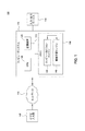
[0022]図1は、1つの実施形態による、ビデオ分析及び挙動認識システム100の構成要素を示す。図示のように、挙動認識システム100は、ビデオ入力源105、ネットワーク110、コンピュータシステム115、並びに入力デバイス及び出力デバイス118(例えば、モニタ、キーボード、マウス、プリンタなど)を含む。ネットワーク110は、ビデオ入力部105によって記録されたビデオデータをコンピュータシステム115に送出してもよい。例示として、コンピュータシステム115は、CPU120と、記憶装置125(例えば、ディスクドライブ、光ディスクドライブなど)と、コンピュータビジョンエンジン135及び機械学習エンジン140の両方を含むメモリ130とを含む。以下でさらに詳細に説明するように、コンピュータビジョンエンジン135及び機械学習エンジン140は、ビデオ入力部105によって供給されるビデオフレームのシーケンスを分析するように構成されたソフトウェアアプリケーションを備えてもよい。
[0022] FIG. 1 illustrates components of a video analysis and
[0023]ネットワーク110は、ビデオ入力源105からのビデオデータ(例えば、ビデオストリーム(複数可)、ビデオ画像など)を受け取る。ビデオ入力源105は、ビデオカメラ、VCR、DVR、DVD、コンピュータ、ウエブカムデバイスなどとしてもよい。例えば、ビデオ入力源105は、一定の区域(例えば、地下鉄駅、駐車場、建物の入口/出口など)に向けられ、そこで起こるイベントを記録する固定ビデオカメラとしてもよい。一般に、カメラの視野内の区域はシーンと呼ばれる。ビデオ入力源105は、指定のフレームレート(例えば、毎秒24フレーム)での個々のビデオフレームのシーケンスとしてシーンを記録するように構成してもよく、ここで、各フレームは固定した数の画素(例えば、320×240)を含む。各フレームの各画素は、色値(例えば、RGB値)又はグレースケール値(例えば、0〜255の間の輝度値)を指定してもよい。さらに、ビデオストリームは、既知のそのようなフォーマット、例えば、MPEG2、MJPEG、MPEG4、H.263、H.264などを使用してフォーマットしてもよい。
[0023] The
[0024]上記のように、コンピュータビジョンエンジン135は、この生情報を分析し、ビデオストリーム中の活動性物体を識別し、位置ずれしたカメラ画像を検出し、機械学習エンジン140によって使用される様々な外観及び運動学的特徴を識別して、物体分類を引き出し、そのような物体の動作及び相互作用に関する様々なメタデータを引き出し、この情報を機械学習エンジン140に供給するように構成してもよい。そして次に、機械学習エンジン140は、ある期間にわたってシーン内で生じるイベント(及びイベントのタイプ)に関する詳細を評価し、観察し、学習し、記憶するように構成してもよい。
[0024] As noted above, the
[0025]1つの実施形態では、機械学習エンジン140は、コンピュータビジョンエンジン135が発生したデータを受け取る。機械学習エンジン140は、受け取ったデータを分析し、類似の視覚及び/又は運動学的特徴を有する物体をクラスタ化し、ビデオフレームに示されたイベントの意味表示を構築するように構成してもよい。ある期間にわたって、機械学習エンジン140は、所与のクラスタにマップする物体の予測される挙動のパターンを学習する。このように、ある期間にわたって、機械学習エンジンは、正常なイベント及び/又は異常なイベントを識別するためにこれらの観察されたパターンから学習する。すなわち、前もって定義されたパターン、物体、物体タイプ、又は活動度を有するのではなく、機械学習エンジン140は、どんな異なる物体タイプが観察されたかについてのそれ自体のモデル(例えば、運動学的特徴及び/又は外観特徴のクラスタに基づいて)、並びに所与の物体タイプの予測される挙動のモデルを構築する。その後、機械学習エンジンは、観察したイベントの挙動が異常かどうかを先の学習に基づいて決定してもよい。
[0025] In one embodiment, the
[0026]正常/異常な挙動/イベントが決定されたかどうか、及び/又はそのような挙動/イベントが何であるかを記述するデータを、出力デバイス118に供給し、警報、例えば、GUIインタフェース画面に表示される警報メッセージを発行してもよい。
[0026] Data describing whether a normal / abnormal behavior / event has been determined and / or what such a behavior / event is is provided to the
[0027]一般に、コンピュータビジョンエンジン135は、ビデオデータ、すなわち、カメラによって捕捉されたフレームのシーケンスを実時間で処理する。しかしながら、コンピュータビジョンエンジン135及び機械学習エンジン140によって情報を処理する時間スケールが異なることがある。例えば、1つの実施形態では、コンピュータビジョンエンジン135は、受け取ったビデオデータをフレームごとに処理し、一方、機械学習エンジン140は、Nフレームごとに特徴づけてデータを処理する。言い換えれば、コンピュータビジョンエンジン135はフレームごとに実時間で分析して、フレームで観察された物体に関連する1組の運動学的データ及び外観データを引き出すが、機械学習エンジン140はビデオ入力部の実時間フレームレートによって制約されない。
[0027] In general, the
[0028]しかしながら、図1は、挙動認識システム100の1つの可能な構成を単に示していることに留意されたい。例えば、ビデオ入力源105がネットワーク110を介してコンピュータシステム115に接続されるように示されているが、ネットワーク110が必ずしも存在するとは限らず、又は必要であるとは限らない(例えば、ビデオ入力源105は、コンピュータシステム115に直接接続してもよい)。さらに、挙動認識システム100の様々な構成要素及びモジュールを他のシステムに実装してもよい。例えば、1つの実施形態では、コンピュータビジョンエンジン135は、ビデオ入力部デバイスの一部として(例えば、ビデオカメラに直接結線されたファームウェア構成要素として)実装してもよい。そのような場合、ビデオカメラの出力は、分析のために機械学習エンジン140に供給してもよい。同様に、コンピュータビジョンエンジン135及び機械学習エンジン140からの出力は、コンピュータネットワーク110を介して他のコンピュータシステムに供給してもよい。例えば、コンピュータビジョンエンジン135及び機械学習エンジン140は、サーバシステムに設置され、多数の入力源(すなわち、多数のカメラ)からのビデオを処理するように構成してもよい。そのような場合、別のコンピュータシステムで作動しているクライアントアプリケーション260は、ネットワーク110を介して結果を要求する(又は受け取る)ことができる。
However, it should be noted that FIG. 1 merely illustrates one possible configuration of the
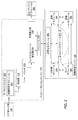
[0029]図2は、1つの実施形態による、図1に最初に示したコンピュータビジョンエンジン135及び機械学習エンジン140の構成要素をさらに示す。図示のように、コンピュータビジョンエンジン135は、データインジェスタ(data ingestor)205、検出器210、トラッカ215、コンテキストイベント発生器220、警報発生器236、及びイベントバス230を含む。全体として、構成要素205、210、215、及び220は、ビデオ入力源105によって供給されたビデオフレームの入来シーケンスを処理するためのパイプラインを備える(構成要素を連結する実線矢印によって示される)。1つの実施形態では、構成要素210、215、及び220は各々本明細書で説明する機能を備えるように構成されたソフトウェアモジュールを備えてもよい。当然、構成要素205、210、215、及び220は、特定の場合の必要性に適合するように組み合わせる(又はさらに細分する)ことができ、さらに、追加の構成要素をビデオ監視システムに付加してもよい(又は、いくつかを取り除くことができる)ことを当業者は認識されよう。
[0029] FIG. 2 further illustrates components of the
[0030]1つの実施形態では、データインジェスタ205はビデオ入力源105からの生ビデオ入力を受け取る。データインジェスタ205は、入力データを前処理し、その後、その入力データを検出器210に送るように構成してもよい。例えば、データインジェスタ205は、供給されたビデオの各フレームを、固定又は静的部分(シーンの背景)と変わりやすい部分の集合(シーンの前景)とに分離するように構成してもよい。フレーム自体は、多重チャネル(例えば、カラービデオでのRGBチャネル又は白黒ビデオでのグレースケールチャネル若しくは輝度チャネル)のための画素値の2次元アレイを含んでもよい。
In one embodiment, the data ingestor 205 receives raw video input from the
[0031]データインジェスタ205は、画像安定化モジュール207を含んでもよい。1つの実施形態では、画像安定化モジュール207は、画像を背景物体と前景物体とに分離する前に、ビデオカメラによって捕捉された画像を評価して、カメラの移動が原因で画像を安定化させる必要があるかどうかを決定するように構成される。そうするために、画像安定化モジュール207は基準画像を発生し、基準画像と対照して現在の画像の安定性を評価してもよい。例えば、1つの実施形態では、最初の生カメラ画像を使用して安定化させ始める。代替として、現在の背景画像を使用してもよい。基準画像は、定期的に、例えば5分ごとに更新してもよい。 [0031] The data ingestor 205 may include an image stabilization module 207. In one embodiment, the image stabilization module 207 evaluates the image captured by the video camera and stabilizes the image due to camera movement before separating the image into background and foreground objects. Configured to determine if needed. To do so, the image stabilization module 207 may generate a reference image and evaluate the stability of the current image against the reference image. For example, in one embodiment, the first raw camera image is used to begin stabilization. Alternatively, the current background image may be used. The reference image may be updated regularly, for example, every 5 minutes.
[0032]基準画像が決定された後、画像安定化モジュール207は1組の位置合わせ領域を決定してもよい。例えば、画像安定化モジュールは、基準画像中の1組の特徴の豊富な区域(例えば、80×80画素格子)を識別してもよい。より詳細には、画像安定化は、カーネル密度推定を使用して基準画像内の最高特徴密度長方形領域を検出してもよい。これらの領域は、特徴密度の降順に保管してもよい。最高特徴密度領域を使用して、後続の生画像の位置合わせを決定する。 [0032] After the reference image is determined, the image stabilization module 207 may determine a set of alignment regions. For example, the image stabilization module may identify a set of feature rich areas (eg, an 80 × 80 pixel grid) in the reference image. More specifically, image stabilization may use kernel density estimation to detect the highest feature density rectangular region in the reference image. These areas may be stored in descending order of feature density. The highest feature density region is used to determine the alignment of subsequent raw images.
[0033]画像安定化モジュール207は特徴の豊富な位置合わせ領域を使用して、現在のフレームを安定化させる必要があるかどうかを識別する。そうするために、画像安定化モジュールは、基準画像からスピードアップロバスト特徴(SURF)を抽出し、後続のフレームのSURFを追跡して、追跡特徴の大多数が固定のままであるか又は整合的アフィン変換(consistent affine transformation)を示すかどうかを決定する。現在のフレームにおいて特徴が固定である場合、安定化は必要でない。 [0033] Image stabilization module 207 uses the feature rich registration region to identify whether the current frame needs to be stabilized. To do so, the image stabilization module extracts the speed-up robust feature (SURF) from the reference image and tracks the SURF of subsequent frames so that the majority of the tracking features remain fixed or consistent. Determine whether to indicate affine transformation (consistent affine transformation). If the feature is fixed in the current frame, stabilization is not necessary.
[0034]そうでない場合には、画像安定化モジュール207は、基準フレームの識別された位置合わせ領域に基づいて画像を位置合わせする。領域を位置合わせしながら、画像安定化モジュールは、特徴を、現在のフレームの追跡位置から基準フレームに基づく位置合わせされた位置に変換するためのアフィン変換行列を見いだす。 [0034] Otherwise, the image stabilization module 207 aligns the image based on the identified alignment region of the reference frame. While aligning the region, the image stabilization module finds an affine transformation matrix for transforming the features from the tracking position of the current frame to an aligned position based on the reference frame.
[0035]1つの実施形態では、検出器210は、適応共鳴理論(ART)ネットワークを使用して画素ごとに背景状態をモデル化してもよい。すなわち、各画素は、その画素をモデル化するARTネットワークを使用して、シーン前景又はシーン背景を示すように分類され得る。当然、シーン前景とシーン背景との間を区別するための他の手法を使用してもよい。 [0035] In one embodiment, the detector 210 may model the background state on a pixel-by-pixel basis using an adaptive resonance theory (ART) network. That is, each pixel can be classified to show the scene foreground or scene background using an ART network that models that pixel. Of course, other techniques for distinguishing between the scene foreground and the scene background may be used.
[0036]追加として、検出器210は、シーンのどの画素が前景を示すように分類されるか、逆に、どの画素がシーン背景を示すように分類されるかを識別するのに使用されるマスクを発生するように構成してもよい。次に、検出器210は、シーン前景の一部分を含むシーンの領域(前景「ブロブ」又は「パッチ」と呼ばれる)を識別し、この情報をパイプラインの後続の段に供給する。追加として、シーン背景を示すように分類された画素を使用して、シーンをモデル化する背景画像を発生させてもよい。 [0036] Additionally, detector 210 is used to identify which pixels in the scene are classified to represent the foreground, and conversely, which pixels are classified to represent the scene background. You may comprise so that a mask may be generated. The detector 210 then identifies the area of the scene (referred to as the foreground “blob” or “patch”) that contains a portion of the scene foreground and provides this information to subsequent stages in the pipeline. Additionally, background images that model the scene may be generated using pixels that are classified to represent the scene background.
[0037]1つの実施形態では、検出器210は、シーンの流れを検出するように構成してもよい。例えば、前景パッチが分離された後、検出器210は、フレームごとに、すべての前景パッチの辺及び隅を検査する。検出器210は、単一の物体又は運動の単一の結合に属する可能性が最も高い同様の運動の流れで移動する前景パッチを識別する。検出器210は、前景物体を識別したとき、この情報をトラッカ215に送る。 [0037] In one embodiment, detector 210 may be configured to detect scene flow. For example, after foreground patches are separated, detector 210 inspects all foreground patch edges and corners for each frame. The detector 210 identifies foreground patches that move in a similar motion stream that most likely belong to a single object or a single combination of motion. When the detector 210 identifies the foreground object, it sends this information to the tracker 215.
[0038]トラッカ215は、検出器210によって生成された前景パッチを受け取り、パッチに対する計算モデルを発生してもよい。例えば、トラッカ215は、この情報と、生ビデオの連続する各フレームとを使用して、例えば、前景物体がシーンのまわりを移動するとき所与の前景パッチによって示される前景物体の運動を追跡しようとするように構成してもよい。すなわち、トラッカ215は、前景物体をフレームごとに追跡することによって、コンピュータビジョンエンジン135の他の要素に対する連続性をもたらす。トラッカ215は、さらに、前景物体の様々な運動学的特徴及び/又は外観特徴、例えば、サイズ、高さ、幅、面積(画素における)、反射率、光沢リジデティ(shininess rigidity)、速さ、速度などを計算してもよい。
[0038] The tracker 215 may receive the foreground patch generated by the detector 210 and generate a computational model for the patch. For example, the tracker 215 may use this information and each successive frame of raw video to track the foreground object motion indicated by a given foreground patch, for example as the foreground object moves around the scene. You may comprise as follows. That is, the tracker 215 provides continuity to other elements of the
[0039]コンテキストイベント発生器220は、パイプラインの他の段からの出力を受け取ってもよい。この情報を使用して、コンテキストプロセッサ220は、(トラッカ構成要素215によって)追跡された物体に関するコンテキストイベントのストリームを発生するように構成してもよい。例えば、コンテキストイベント発生器220は、マイクロ特徴ベクトルのストリームと物体の運動学的観察情報とをパッケージ化し、これを機械学習エンジン140に、例えば5Hzの速度で出力してもよい。1つの実施形態では、コンテキストイベントは軌跡としてパッケージ化される。本明細書で使用するとき、軌跡は、一般に、連続するフレーム又はサンプルにおける特定の前景物体の運動学的データをパッケージ化するベクトルを指す。軌跡の各要素は、特定の時点にその物体に対して捕捉された運動学的データを表す。一般に、完全な軌跡は、例えば、前景物体が、最初に、連続する各観察情報と一緒にビデオのフレームで観察されたときから前景物体がシーンを出て行く(又はフレーム背景に消滅する点に静止する)ときまでに得られた運動学的データを含む。それゆえに、コンピュータビジョンエンジン135が5Hzの速度で動作していると仮定すると、物体の軌跡は、完了するまで、200ミリ秒ごとに更新される。コンテキストイベント発生器220は、さらに、形状、幅、及び他の物理的特徴などの様々な外観属性を評価し、各属性に数値スコアを割り当てることによってすべての前景物体の外観データを計算しパッケージ化してもよい
[0039] The context event generator 220 may receive output from other stages of the pipeline. Using this information, context processor 220 may be configured to generate a stream of context events for the tracked object (by tracker component 215). For example, the context event generator 220 may package the stream of micro feature vectors and kinematic observation information of the object and output this to the
[0040]コンピュータビジョンエンジン135は、シーン中の追跡物体の運動及び動作を記述する構成要素205、210、215、及び220からの出力を獲得して、この情報をイベントバス230を通して機械学習エンジン140に供給してもよい。例示として、機械学習エンジン140は、分類器モジュール235、意味モジュール245、マッパモジュール240、認識モジュール250、コルテックスモジュール(cortex module)270、及び正常化モジュール265を含む。
[0040] The
[0041]分類器モジュール235は、コンピュータビジョンエンジン135からの外観データなどのコンテキストイベントを受け取り、データをニューラルネットワークにマッピングする。1つの実施形態では、ニューラルネットワークは、自己組織化マップ(SOM)とARTネットワークとの組合せである。データは、互いに関連して繰り返し生じる特徴によってクラスタ化され組み合わされる。次に、それらのたびたび生じるタイプに基づいて、分類器モジュール235は物体のタイプを定義する。例えば、分類器モジュール235は、例えば高い光沢リジデティ及び反射率を有する前景パッチをタイプ1物体として定義してもよい。次に、これらの定義されたタイプは、システムの残りの全体にわたって伝わる。
[0041] The classifier module 235 receives context events such as appearance data from the
[0042]コルテックスモジュール270は、運動学的データをコンピュータビジョンエンジン135から受け取り、データをSOM−ARTネットワークなどの)ニューラルネットワークにマッピングする。1つの実施形態では、SOM−ARTネットワークは運動学的データをクラスタ化して、シーン中のイベントの共通シーケンスを構築する。別の実施形態では、SOM−ARTネットワークは相互作用している軌跡からの運動学的データをクラスタ化して、シーン中の共通相互作用を構築する。シーン内のイベント及び相互作用の共通シーケンスを学習することによって、コルテックスモジュール270は、異常なシーケンス及び相互作用を検出するときに機械学習エンジンを支援する。
[0042] Cortex module 270 receives kinematic data from
[0043]マッパモジュール240は、前景パッチについてシステムにわたって空間的及び時間的相関並びに挙動を探索することによってこれらのタイプを使用して、どこで及びいつイベントが生じそうか又は生じそうでないかのマップを作り出す。1つの実施形態では、マッパモジュール240は、時間メモリARTネットワーク、空間メモリARTネットワーク、及び統計エンジンを含む。例えば、マッパモジュール240は、タイプ1物体のパッチを探すことができる。空間メモリARTネットワークは統計エンジンを使用して、シーンのどこにこれらのパッチが現われるか、どの方向にこれらのパッチは進む傾向があるか、どれくらい速くこれらのパッチは進むか、これらのパッチは方向を変えるかどうかなどのようなこれらの物体の統計データを作り出す。次に、マッパモジュール240はこの情報のニューラルネットワークを構築し、ニューラルネットワークは物体挙動の比較対象となるメモリテンプレートになる。時間メモリARTネットワークは統計エンジンを使用して、タイムスライスのサンプリングに基づいて統計データを作り出す。1つの実施形態では、初期サンプリングは、30分間隔ごとに行われる。タイムスライス内で多くのイベントが生じる場合、時間分解能は、より細かい分解能に動的に変更され得る。逆に、タイムスライス内でイベントがほとんど生じない場合、時間分解能は、より粗い分解能に動的に変更され得る。
[0043] The
[0044]1つの実施形態では、意味モジュール245は、シーン内の運動のパターン又は軌跡を識別し、普遍化により異常な挙動のシーンを分析する。シーンをモザイク模様にし、前景パッチを多くの異なるテッセラに分割することによって、意味モジュール245は、物体の軌跡の跡を辿り、軌跡からパターンを学習する。意味モジュール245はこれらのパターンを分析し、これらのパターンを他のパターンと比較する。物体がシーンに入るとき、意味モジュール245は適応格子を構築し、物体とその軌跡とを格子上にマッピングする。より多くの特徴及び軌跡が格子上に取り込まれるとき、機械学習エンジンは、シーンに共通している軌跡を学習し、さらに、正常挙動を異常挙動と区別する。 [0044] In one embodiment, the semantic module 245 identifies motion patterns or trajectories in the scene and analyzes the unusually behaving scene by universalization. By making the scene a mosaic and dividing the foreground patch into many different tessellass, the semantic module 245 follows the trail of the object's trajectory and learns the pattern from the trajectory. The semantic module 245 analyzes these patterns and compares these patterns with other patterns. When an object enters the scene, the semantic module 245 builds an adaptive grid and maps the object and its trajectory onto the grid. As more features and trajectories are captured on the grid, the machine learning engine learns trajectories that are common to the scene and further distinguishes normal behavior from abnormal behavior.
[0045]1つの実施形態では、認識モジュール250は、知覚メモリ、エピソードメモリ、長期メモリ、及び作業領域を含む。一般に、作業領域は、機械学習エンジン140のための計算エンジンを備える。例えば、作業領域は、知覚メモリからの情報をコピーし、エピソードメモリ及び長期メモリから関連する記憶を取り出し、実行すべきコードレットを選択するように構成してもよい。1つの実施形態では、コードレットは、イベントの異なるシーケンスを評価し、あるシーケンスが別のシーケンス(例えば、有限状態機械)にどのように続くことができるか(又はさもなければ関連するか)を決定するように構成されたソフトウェアプログラムである。より一般的には、コードレットは、機械学習エンジンに送り込まれたデータのストリームから興味あるパターンを検出するように構成されたソフトウェアモジュールを備えてもよい。そして次に、コードレットは、エピソードメモリ及び長期メモリに記憶を作り出し、取り出し、強化し、又は修正してもよい。実行のためのコードレットを繰り返してスケジューリングし、認識モジュール250の作業領域に/から記憶及び知覚内容をコピーすることによって、機械学習エンジン140は、シーン内に生じる挙動パターンに関して観察し学習するのに使用される認識サイクルを実行する。
[0045] In one embodiment, the recognition module 250 includes a perceptual memory, an episode memory, a long term memory, and a work area. In general, the work area includes a calculation engine for the
[0046]1つの実施形態では、知覚メモリ、エピソードメモリ、及び長期メモリは、挙動のパターンを識別し、シーンで起こるイベントを評価し、観察情報を符号化及び格納するのに使用される。一般に、知覚メモリは、コンピュータビジョンエンジン135の出力(例えばコンテキストイベントのストリーム)を受け取る。エピソードメモリは、観察されたイベントを表すデータを、特定のエピソードに関連する詳細、例えば、イベントの関連する時間及び空間の詳細を記述する情報とともに格納する。すなわち、エピソードメモリ252は、特定のイベントの具体的詳細、すなわち、特定の車両(自動車A)が9:43AMに駐車スペース(駐車スペース5)であると思われる場所に移動したなどのシーン内で「何がどこで」生じたかを符号化することができる。 [0046] In one embodiment, perceptual memory, episode memory, and long-term memory are used to identify behavioral patterns, evaluate events that occur in the scene, and encode and store observation information. In general, the perceptual memory receives the output of the computer vision engine 135 (eg, a stream of context events). Episode memory stores data representing observed events, along with information describing details related to a particular episode, eg, time and space details related to the event. That is, the episode memory 252 is stored in a specific detail of a specific event, that is, in a scene in which a specific vehicle (car A) has moved to a place where it is thought that it is a parking space (parking space 5) It can be encoded what happened and where.
[0047]対照的に、長期メモリは、シーンで観察されたイベントを普遍化するデータを格納することができる。車両駐車の例を続けると、長期メモリは、「車両はシーン中の特定の場所に駐車する傾向がある」、「駐車するとき、車両は一定の速度で移動する傾向がある」、「車両駐車の後、人々は車両に隣接したシーンに現われる傾向がある」などのような観察情報を捕捉する情報と、シーン中の物体の挙動を分析することによって学習された普遍化とを符号化してもよい。「車両」の使用は類例として提供されていることに留意されたい。しかしながら、厳密に言えば、長期メモリもエピソードメモリも、「人」又は「車両」などの実体を全く知らない。代わりに、これらの構造体は、ある期間にわたって変化する画素値の観察情報から導き出された統計データを格納する。このように、長期メモリは、何がシーン内で起こったかに関する観察情報を、特定のエピソードの詳細のうちの多くを取り去った状態で記憶する。このようにして、新しいイベントが生じたとき、エピソードメモリ及び長期メモリからの記憶を使用して、現在のイベントを関連づけて理解することができる、すなわち、新しいイベントは過去の経験と比較され、それにより、ある期間にわたって、長期メモリに格納されている情報に対して強化、減退、及び調節をもたらすことができる。特定の実施形態では、長期メモリは、ARTネットワーク及び疎分散記憶構造体として実現してもよい。しかしながら、重要なことには、この手法は、様々な物体タイプ分類を前もって定義する必要がない。 [0047] In contrast, long-term memory can store data that generalizes events observed in a scene. Continuing with the example of vehicle parking, the long-term memory is: “the vehicle tends to park at a specific location in the scene”, “when parked, the vehicle tends to move at a constant speed”, “vehicle parking Encoding information that captures observational information such as `` People tend to appear in scenes next to vehicles '' and universalization learned by analyzing the behavior of objects in the scene Good. Note that the use of “vehicle” is provided as an example. Strictly speaking, however, neither the long-term memory nor the episode memory knows any entity such as “person” or “vehicle”. Instead, these structures store statistical data derived from observation information of pixel values that change over a period of time. In this way, long-term memory stores observation information regarding what happened in the scene, with much of the details of a particular episode removed. In this way, when a new event occurs, the memory from the episode memory and long-term memory can be used to correlate and understand the current event, i.e. the new event is compared with past experience, This can provide enhancements, decays, and adjustments to information stored in long-term memory over a period of time. In certain embodiments, the long-term memory may be implemented as an ART network and a sparse distributed storage structure. Importantly, however, this approach does not require various object type classifications to be defined in advance.
[0048]1つの実施形態では、モジュール235、240、245、250、及び270は、シーンの異常を検出するように構成してもよい。すなわち、各モジュールは、シーンの過去の観察情報と比べて異常な挙動を識別するように構成してもよい。いかなるモジュールも異常な挙動を識別した場合、警報を発生し、正常化モジュール265を通して警報を送る。例えば、意味モジュール245は、学習したパターン及びモデルを使用して普通でない軌跡を検出する。前景物体がぶらつく挙動を示す場合、例えば、意味モジュール245は、ぶらつきモデルを使用して物体軌跡を評価し、続いて警報を発生し、警報を正常化モジュール265に送る。警報を受け取った際、正常化モジュール265は、警報を発行すべきかどうかを評価する。
[0048] In one embodiment,
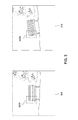
[0049]図3は、1つの実施形態による、基準画像と、カメラによって捕捉された現在の画像とのグラフィック表示を示す。基準画像305及び現在の画像310は各々所与のシーン、すなわち、公園ベンチ及び砂利を有する観察区域のフレームを示す。先に述べたように、画像安定化モジュール207は、続いて捕捉される生ビデオ画像の安定性を評価することにおいて使用するための基準画像を得ることができる。初期の基準フレームは最初の生カメラ画像としてもよい。画像安定化モジュール207は、その後、基準画像を定期的に(例えば、5分ごとに)更新してもよい。
[0049] FIG. 3 illustrates a graphical display of a reference image and a current image captured by a camera, according to one embodiment. The
[0050]基準画像が得られるか又は更新されると、画像安定化モジュール207は、基準画像からスピードアップロバスト特徴(SURF)を抽出し、隅、辺、又は他のコンテキスト情報(contextual information)などにおいて高い特徴密度を有する画像内の場所を確認する。1つの実施形態では、画像安定化モジュール207は均一性カーネル密度推定アルゴリズムを適用して、画像の最高特徴密度領域を決定する。画像安定化モジュール207は、安定化が必要な場合、そのような領域を位置合わせ領域として使用する。位置合わせ領域が識別された後、画像安定化モジュール207は、基準フレームで抽出されたSURFを続いて捕捉されるフレーム中で追跡して、特徴平行移動、回転、又はスケーリングなどの特徴のいかなる変化も検出してもよい。さらに、識別された位置合わせ領域が、安定化の後、不十分な結果をもたらす(例えば、位置合わせ領域の特徴のうちのいくつかが前景物体に対応することに起因して)場合、画像安定化モジュール207は、安定化のために、2番目に高い特徴密度の位置合わせ領域(など)を使用してもよい。 [0050] Once the reference image is obtained or updated, the image stabilization module 207 extracts speed-up robust features (SURF) from the reference image, such as corners, edges, or other contextual information. To identify locations in the image that have a high feature density. In one embodiment, the image stabilization module 207 applies a uniformity kernel density estimation algorithm to determine the highest feature density region of the image. The image stabilization module 207 uses such a region as an alignment region when stabilization is required. After the registration region is identified, the image stabilization module 207 tracks the SURF extracted in the reference frame in the subsequent captured frame to make any changes in the feature such as feature translation, rotation, or scaling. May also be detected. Furthermore, image stabilization if the identified registration region produces poor results after stabilization (eg, due to some of the registration region features corresponding to foreground objects). The conversion module 207 may use the second highest feature density alignment region (such as) for stabilization.
[0051]基準画像305は、例示の位置合わせ領域307a(フレーム内に点線のボックスとして示されている)を含む。画像安定化モジュール207は基準フレームで抽出された特徴を追跡して、後続の画像がずれている(例えば、所与のフレーム中の特徴が、基準画像305の位置合わせ領域307aと比較したとき位置ずれしている)かどうかを検出する。画像が位置ずれしている場合、画像安定化モジュール207は位置合わせ領域を使用して、画像を再位置合わせする際に適用するアフィン変換行列を推定する。実際には、位置合わせ領域は図3に示したものよりも小さくしてもよい。例えば、経験によれば、81×81画素の位置合わせ領域を使用して良好な結果がもたらされる。
[0051] The
[0052]現在の画像310は、特徴の位置が基準画像305から逸脱しているフレームの一例である。例示として、現在の画像310は、基準画像305と同じシーンであるが、捕捉された特徴にはわずかな量の平行移動及び回転がある場合を示している。そのような逸脱は、例えば、周囲の調和運動又は振動から生じることがある(例えば、シーンを通り過ぎて振動を引き起こす自動車、風、カメラの不安定な装着などによって)。図示のように、現在の画像310は、位置合わせ領域307aと同じフレームの位置にある位置合わせ領域307bを含む。位置合わせ領域307a内の特徴の位置と比較すると、位置合わせ領域307b内の特徴の位置は回転している。画像安定化モジュール207は、基準画像305のSURFを現在の画像310と比較するときにそのような回転(又は他のアフィン変換)を検出し、続いて、現在の画像310を安定化させる必要があると決定してもよい。
[0052] The
[0053]図4は、1つの実施形態による、カメラによって捕捉された位置ずれしたフレームを安定化させる方法400を示す。経験によれば、方法400が有効に機能するには、ビデオサンプルが取得されるレート(すなわち、フレームレート)は、補償されつつあるシーン不安定性を引き起こす振動又は運動が生じる固有レートと少なくとも一致しなければならない(多少超えることが好ましい)ことに留意されたい。 [0053] FIG. 4 illustrates a method 400 for stabilizing misaligned frames captured by a camera, according to one embodiment. Experience has shown that for the method 400 to work effectively, the rate at which video samples are acquired (ie, the frame rate) is at least consistent with the natural rate at which the vibration or motion that causes the scene instability being compensated occurs. Note that it must be (preferably slightly over).
[0054]挙動認識システムの開始の際などに画像安定化モジュール207が初期基準画像を既に得ていると仮定し、さらに、初期位置合わせ領域が既に検出されていると仮定する。ステップ405において、データインジェスタ205は入力源105から生ビデオ入力(すなわち、現在観察されている画像)を受け取る。ステップ410において、画像安定化モジュール207は、基準画像を更新すべきかどうかを決定する。例えば、画像安定化モジュール207は、生ビデオ入力に基づいて基準画像を定期的に更新してもよい。更新された基準画像は、再位置合わせされた画像に対応してもよい。別の場合、画像安定化モジュールは、新しい基準画像を、背景モデルに十分正しく合っている現在のものとして探すように構成してもよい。
[0054] Assume that the image stabilization module 207 has already obtained an initial reference image, such as at the start of the behavior recognition system, and further assume that an initial registration region has already been detected. In
[0055]基準画像を更新した後、画像安定化モジュール207は、基準画像の長方形位置合わせ領域を検出する。1つの実施形態では、画像安定化モジュール207は、基準画像の画素領域(例えば、81×81領域)にわたって均一性カーネル密度推定アルゴリズムを適用して、最高特徴密度領域を識別する。実際には、画像安定化モジュール207は4つまでのそのような領域を識別してもよいが、画像安定化モジュール207はより多くの領域を識別するように構成してもよい。画像安定化モジュール207は、最高密度の特徴を有する領域を位置合わせ領域として指定してもよい。位置合わせ領域が識別された後、画像安定化モジュール207は、画像安定化に使用するために領域を降順にランク付けしてもよい。 [0055] After updating the reference image, the image stabilization module 207 detects a rectangular alignment region of the reference image. In one embodiment, the image stabilization module 207 applies a uniformity kernel density estimation algorithm over the pixel region (eg, 81 × 81 region) of the reference image to identify the highest feature density region. In practice, the image stabilization module 207 may identify up to four such regions, but the image stabilization module 207 may be configured to identify more regions. The image stabilization module 207 may designate an area having the highest density feature as an alignment area. After the registration regions are identified, the image stabilization module 207 may rank the regions in descending order for use in image stabilization.
[0056]ステップ425において、画像安定化モジュール207は、現在観察されている画像が基準フレームに対して適切に位置合わせされていないどうかを決定する。すなわち、基準フレームを現在のフレームと比較したとき、現在のフレームの追跡特徴の大多数が同じ場所にある場合、画像が適切な位置合わせ状態にある可能性が最も高く、安定化は必要とされない。しかしながら、画像安定化モジュール207が、回転、変換、及びスケーリングなどの、フレーム中の特徴にアフィン変換を検出した場合、画像安定化モジュール207は、フレームを安定化させる必要があることがある。1つの実施形態では、ピラミッド型ルーカス−カナデオプティカルフロー分析法を使用して、特徴を追跡してもよい。
[0056] In
[0057]そうならば、画像安定化モジュール207は、指定位置合わせ領域を使用して、位置合わせアルゴリズムの使用により現在の画像を安定化させる。アルゴリズムは、指定位置合わせ領域に基づいて画像全体のアフィン変換行列を推定することによって現在の画像を安定化させる。アルゴリズムはアフィン変換行列を使用して、画像が安定になるまで不安定な画像を歪ませる。識別されたアフィン変換行列により、画像安定化モジュール207は、特徴を、現在の画像の追跡位置から基準画像に基づく位置合わせされた位置に変換してもよい。 [0057] If so, the image stabilization module 207 uses the specified registration region to stabilize the current image by using a registration algorithm. The algorithm stabilizes the current image by estimating the affine transformation matrix of the entire image based on the specified alignment region. The algorithm uses an affine transformation matrix to distort unstable images until the image is stable. Depending on the identified affine transformation matrix, the image stabilization module 207 may convert the feature from a tracking position of the current image to a registered position based on the reference image.
[0058]推定アフィン変換行列を得るために、画像安定化モジュール207は4つのパラメータを位置合わせアルゴリズムに渡す。1)指定位置合わせ領域を位置合わせするための反復の数、2)現在の画像の位置合わせ領域と基準画像の位置合わせ領域との間の水平平行移動のイプシロン差(ε)、3)現在の画像の位置合わせ領域と基準画像の位置合わせ領域との間の垂直平行移動のε、4)現在の画像の位置合わせ領域と基準画像の位置合わせ領域との間の回転のε。1つの実施形態では、逆合成法を使用して、指定位置合わせ領域を調節してもよい。一般に、アルゴリズムは勾配降下分析を使用して、平行移動誤差及び回転誤差を減少させる。すなわち、アルゴリズムは所与のパラメータを使用して、最急降下行列を計算する。最急降下行列は、2次元の勾配行列である。現在の画像が基準画像に完全に位置合わせされている場合、水平及び垂直勾配値は0に等しい。反復ごとに、位置合わせアルゴリズムは、誤差値がε値の方にできるだけ近くに移動するように位置合わせ領域を再調節する。1つの実施形態では、反復ごとの位置合わせ領域が局所最小限内にとどまっている(すなわち、基準画像からずれている)場合には、画像を安定化させるさらなる洗練のために摂動理論法を使用することもできる。さらに、反復ごとに、アルゴリズムは、位置合わせを達成するのに必要とされる推定アフィン変換行列を更新する。指定の反復を完了した後(又は平行移動値及び回転値がε値を下回った後)、アルゴリズムは、結果として生じたアフィン変換行列を現在の画像全体に適用する。 [0058] To obtain an estimated affine transformation matrix, the image stabilization module 207 passes four parameters to the registration algorithm. 1) the number of iterations to align the specified alignment area, 2) the horizontal translation epsilon difference (ε) between the alignment area of the current image and the alignment area of the reference image, and 3) the current Ε for vertical translation between the image registration region and the reference image alignment region, 4) ε for rotation between the current image registration region and the reference image alignment region. In one embodiment, a reverse alignment method may be used to adjust the designated alignment area. In general, the algorithm uses gradient descent analysis to reduce translation and rotation errors. That is, the algorithm uses the given parameters to calculate the steepest descent matrix. The steepest descent matrix is a two-dimensional gradient matrix. If the current image is perfectly aligned with the reference image, the horizontal and vertical slope values are equal to zero. At each iteration, the registration algorithm readjusts the registration area so that the error value moves as close as possible to the ε value. In one embodiment, use perturbation theory methods for further refinement to stabilize the image if the registration region for each iteration remains within the local minimum (ie, deviates from the reference image). You can also Furthermore, at each iteration, the algorithm updates the estimated affine transformation matrix needed to achieve alignment. After completing the specified iteration (or after the translation and rotation values are below the ε value), the algorithm applies the resulting affine transformation matrix to the entire current image.
[0059]さらに、1つの実施形態では、画像安定化モジュール207は、画像を再位置合わせした後、統計学的重みを位置合わせ領域に割り当ててもよい。そうすることにより、画像安定化モジュール207は、基準画像及び位置合わせされた画像が設定可能な許容範囲内にあるかどうか、例えば、位置合わせされた画像の特徴が基準画像にどれくらい正しく合っているかを決定してもよい。例えば、画像安定化モジュール207は、最初に、画像中の最高密度の特徴を有する位置合わせ領域を決定してもよいが、その領域は、領域の密度に寄与する前景物体の移動に起因して有用性が限定的であることがある。その結果、初期の位置合わせ領域は不十分な安定化をもたらすことがある。 [0059] Further, in one embodiment, the image stabilization module 207 may assign statistical weights to the registration regions after re-registering the images. By doing so, the image stabilization module 207 determines whether the reference image and the registered image are within a settable tolerance, for example, how correctly the features of the registered image match the reference image. May be determined. For example, the image stabilization module 207 may first determine the registration region with the highest density feature in the image, which is due to the movement of foreground objects that contribute to the density of the region. Usefulness may be limited. As a result, the initial alignment region may provide insufficient stabilization.
[0060]統計学的重みは、アフィン変換行列によって必要とされる平行移動、回転、及びスケーリングの評価基準に基づく重ね合わせ誤差に基づいて計算してもよい。重ね合わせ誤差が、設定された量の範囲を超えている(やはり位置合わせ領域の重ね合わせ及び現在のフレームに対して測定された)場合、2番目に高い特徴密度の位置合わせ領域を使用して、現在のフレームを位置合わせしてもよい。それゆえに、特定の位置合わせ領域が、低い誤差をもつ結果を連続的に生成する(例えば、基準画像と現在の画像との位置合わせ領域の重ね合わせに対して)場合、画像安定化モジュール207は、領域の統計学的重みを強化してもよい。逆に、位置合わせ領域が高い誤差をもつ結果を生成し始めた場合、画像安定化モジュール207は、領域の統計学的重みを減少してもよい。より一般的には、現在の領域が所与のわずかな許容範囲内に画像を安定化させない場合、統計的有意性は減少される。他方では、所与の許容範囲内に画像を安定化させる有用な領域の有意性は増加される。領域は統計学的重みに基づいて連続的にソートされ、最も高い統計学的重みをもつ領域が、常に、最初に、現在の画像内の位置合わせのために使用される。 [0060] Statistical weights may be calculated based on overlay errors based on the translation, rotation, and scaling criteria required by the affine transformation matrix. If the registration error exceeds the set amount range (again measured for registration region overlay and current frame), use the second highest feature density registration region The current frame may be aligned. Therefore, if a particular alignment region continuously produces results with low errors (eg, for registration region and registration overlap of the current image), the image stabilization module 207 The statistical weight of the region may be enhanced. Conversely, if the registration region begins to produce a result with a high error, the image stabilization module 207 may decrease the statistical weight of the region. More generally, statistical significance is reduced if the current region does not stabilize the image within a given slight tolerance. On the other hand, the significance of useful regions that stabilize the image within a given tolerance is increased. Regions are sequentially sorted based on statistical weights, and the region with the highest statistical weight is always used first for registration in the current image.
[0061]さらに、コンピュータビジョンエンジンはほぼ実時間でビデオデータを処理する必要があるので、画像安定化モジュール207は、システム性能とフレーム安定化の品質とのバランスをとるためにいくつかの調整可能なパラメータをサポートしてもよい。例えば、画像安定化モジュール207は、許容された又は目標の時間制限により構成してもよい。最後のnフレームを安定化させるのに必要な時間が制限を下回る場合、画像安定化モジュール207は、よりよい安定化を得るためにより多くの計算を許容し、特に、基準画像に一致させるために現在の画像の特徴を変換するのに必要とされるアフィン変換行列を決定するためにより多くの時間を許容してもよい。位置合わせのための時間が多いほど、さらなる安定化を生じさせてもよい。他方では、画像を安定化させる時間が許容時間制限を超える場合、画像安定化モジュール207は、アフィン変換行列を決定するために実行される計算の数を減少させてもよい。そうすることにより、画像安定化モジュールは、ビデオ監視システムの実時間要求に追随できるようになる。 [0061] In addition, since the computer vision engine needs to process video data in near real time, the image stabilization module 207 can be adjusted in several ways to balance system performance and frame stabilization quality. May support various parameters. For example, the image stabilization module 207 may be configured with an allowed or target time limit. If the time required to stabilize the last n frames is below the limit, the image stabilization module 207 allows more calculations to get better stabilization, especially to match the reference image More time may be allowed to determine the affine transformation matrix required to transform the current image features. The more time for alignment, the more stabilization may occur. On the other hand, if the time to stabilize the image exceeds the allowable time limit, the image stabilization module 207 may reduce the number of calculations performed to determine the affine transformation matrix. By doing so, the image stabilization module can follow the real-time requirements of the video surveillance system.
[0062]説明したように、本明細書で提示した実施形態は、ビデオカメラによって以前に捕捉された基準画像に対してずれている画像を安定化させるための技法を提供する。コンピュータビジョンエンジンは、シーンの前景物体から背景物体を分離する前に、所与のシーンの位置ずれした画像を安定化させる。結果として生じる画像は、一貫性があり、コンピュータビジョンエンジン及び機械学習エンジンがビデオストリームに捕捉された画像を適切に分析できるようにすることが有利である。 [0062] As described, the embodiments presented herein provide techniques for stabilizing images that are offset relative to a reference image previously captured by a video camera. The computer vision engine stabilizes the misaligned image of a given scene before separating the background object from the foreground object of the scene. The resulting images are consistent and advantageously allow the computer vision engine and machine learning engine to properly analyze the images captured in the video stream.
[0063]前述は本発明の実施形態を対象とするが、本発明の基本範囲から逸脱することなく本発明の他の及びさらなる実施形態を考案してもよく、本発明の範囲は以下の特許請求の範囲によって決定される。 [0063] While the foregoing is directed to embodiments of the invention, other and further embodiments of the invention may be devised without departing from the basic scope of the invention, the scope of the invention being covered by the following patents: Determined by the claims.
Claims (23)
ビデオカメラによって捕捉されたフレームのストリームを位置合わせすることにおいて使用するために基準フレーム内の候補領域を識別するステップであり、前記候補領域が、各候補領域内の追跡特徴の密度によって降順にソートされる、識別するステップと、
捕捉されたフレームごとに、前記候補領域の中で最も高い密度の追跡特徴を有する候補領域を位置合わせ領域として指定するステップと、
現在のフレームの前記追跡特徴が前記基準フレームの対応する特徴に対して位置ずれしていることに基づいて、前記ストリームが不安定であると決定する際に、
前記位置合わせ領域に基づいて前記現在のフレームのアフィン変換行列を決定するステップと、
前記現在のフレームの前記位置合わせ領域の前記特徴が前記基準フレームの前記対応する特徴と一致するように、前記アフィン変換行列を使用して前記現在のフレームを歪ませるステップと、
前記歪まされた現在のフレームと前記基準フレームとの間の重ね合わせ誤差を識別するステップと、
前記重ね合わせ誤差が許容範囲閾値内にあると決定する際に、前記歪まされた現在のフレームを、安定化されたフレームとして指定するステップと、
を含む、方法。 A method of stabilizing a camera image captured by a video recording device and evaluated by a video analysis application comprising:
Identifying candidate regions within a reference frame for use in aligning a stream of frames captured by a video camera, wherein the candidate regions are sorted in descending order by the density of tracking features within each candidate region An identifying step;
For each captured frame, designating a candidate region having the highest density of tracking features among the candidate regions as an alignment region;
In determining that the stream is unstable based on the tracking feature of the current frame being misaligned with the corresponding feature of the reference frame,
Determining an affine transformation matrix of the current frame based on the alignment region;
Distorting the current frame using the affine transformation matrix such that the feature of the alignment region of the current frame matches the corresponding feature of the reference frame;
Identifying a registration error between the distorted current frame and the reference frame;
Designating the distorted current frame as a stabilized frame in determining that the overlay error is within a tolerance threshold;
Including a method.
前記位置合わせ領域の統計学的重みを減少させるステップと、
2番目に統計的に有意な候補領域を前記位置合わせ領域として指定するステップと、
をさらに含む、請求項6に記載の方法。 In determining that the overlay error is not within the tolerance threshold,
Reducing the statistical weight of the alignment region;
Designating a second statistically significant candidate region as the alignment region;
The method of claim 6, further comprising:
ビデオカメラによって捕捉されたフレームのストリームを位置合わせすることにおいて使用するために基準フレーム内の候補領域を識別するステップであり、前記候補領域が、各候補領域内の追跡特徴の密度によって降順にソートされる、識別するステップと、
捕捉されたフレームごとに、前記候補領域の中で最も高い密度の追跡特徴を有する候補領域を位置合わせ領域として指定するステップと、
現在のフレームの前記追跡特徴が前記基準フレームの対応する特徴に対して位置ずれしていることに基づいて、前記ストリームが不安定であると決定する際に、
前記位置合わせ領域に基づいて前記現在のフレームのアフィン変換行列を決定するステップと、
前記現在のフレームの前記位置合わせ領域の前記特徴が前記基準フレームの前記対応する特徴と一致するように、前記アフィン変換行列を使用して前記現在のフレームを歪ませるステップと、
前記歪まされた現在のフレームと前記基準フレームとの間の重ね合わせ誤差を識別するステップと、
前記重ね合わせ誤差が許容範囲閾値内にあると決定する際に、前記歪まされた現在のフレームを、安定化されたフレームとして指定するステップと、
を含む、コンピュータ可読記憶媒体。 A computer readable storage medium storing instructions that, when executed on a processor, perform operations to stabilize a camera image captured by a video recording device and evaluated by a video analysis application; The operation is
Identifying candidate regions within a reference frame for use in aligning a stream of frames captured by a video camera, wherein the candidate regions are sorted in descending order by the density of tracking features within each candidate region An identifying step;
For each captured frame, designating a candidate region having the highest density of tracking features among the candidate regions as an alignment region;
In determining that the stream is unstable based on the tracking feature of the current frame being misaligned with the corresponding feature of the reference frame,
Determining an affine transformation matrix of the current frame based on the alignment region;
Distorting the current frame using the affine transformation matrix such that the feature of the alignment region of the current frame matches the corresponding feature of the reference frame;
Identifying a registration error between the distorted current frame and the reference frame;
Designating the distorted current frame as a stabilized frame in determining that the overlay error is within a tolerance threshold;
A computer-readable storage medium including:
前記位置合わせ領域の統計学的重みを減少させるステップと、
2番目に統計的に有意な候補領域を前記位置合わせ領域として指定するステップと、
をさらに含む、請求項13に記載のコンピュータ可読記憶媒体。 In determining that the overlay error is not within the tolerance threshold,
Reducing the statistical weight of the alignment region;
Designating a second statistically significant candidate region as the alignment region;
The computer-readable storage medium of claim 13, further comprising:
アプリケーションのホストとして働くメモリであって、該アプリケーションが、前記プロセッサで実行されるときに、ビデオ記録デバイスによって捕捉されビデオ分析アプリケーションによって評価されるカメラ画像を安定化させるための演算を実行する、メモリと、
を備え、前記演算が、
ビデオカメラによって捕捉されたフレームのストリームを位置合わせすることにおいて使用するために基準フレーム内の候補領域を識別するステップであり、前記候補領域が、各候補領域内の追跡特徴の密度によって降順にソートされる、識別するステップと、
捕捉されたフレームごとに、前記候補領域の中で最も高い密度の追跡特徴を有する候補領域を位置合わせ領域として指定するステップと、
現在のフレームの前記追跡特徴が前記基準フレームの対応する特徴に対して位置ずれしていることに基づいて、前記ストリームが不安定であると決定する際に、
前記位置合わせ領域に基づいて前記現在のフレームのアフィン変換行列を決定するステップと、
前記現在のフレームの前記位置合わせ領域の前記特徴が前記基準フレームの前記対応する特徴と一致するように、前記アフィン変換行列を使用して前記現在のフレームを歪ませるステップと、
前記歪まされた現在のフレームと前記基準フレームとの間の重ね合わせ誤差を識別するステップと、
前記重ね合わせ誤差が許容範囲閾値内にあると決定する際に、前記歪まされた現在のフレームを、安定化されたフレームとして指定するステップと、
を含む、システム。 A processor;
A memory that serves as a host for an application that performs operations to stabilize camera images captured by a video recording device and evaluated by a video analysis application when the application is executed on the processor When,
And the operation is
Identifying candidate regions within a reference frame for use in aligning a stream of frames captured by a video camera, wherein the candidate regions are sorted in descending order by the density of tracking features within each candidate region An identifying step;
For each captured frame, designating a candidate region having the highest density of tracking features among the candidate regions as an alignment region;
In determining that the stream is unstable based on the tracking feature of the current frame being misaligned with the corresponding feature of the reference frame,
Determining an affine transformation matrix of the current frame based on the alignment region;
Distorting the current frame using the affine transformation matrix such that the feature of the alignment region of the current frame matches the corresponding feature of the reference frame;
Identifying a registration error between the distorted current frame and the reference frame;
Designating the distorted current frame as a stabilized frame in determining that the overlay error is within a tolerance threshold;
Including the system.
前記位置合わせ領域の統計学的重みを減少させるステップと、
2番目に統計的に有意な候補領域を前記位置合わせ領域として指定するステップと、
をさらに含む、請求項20に記載のシステム。 In determining that the overlay error is not within the tolerance threshold,
Reducing the statistical weight of the alignment region;
Designating a second statistically significant candidate region as the alignment region;
21. The system of claim 20, further comprising:
ビデオカメラによって捕捉されたフレームを位置合わせすることにおいて使用するために基準フレーム内の候補領域を識別するステップであり、前記候補領域が、各候補領域内の追跡特徴の密度によって降順にソートされる、識別するステップと、
捕捉されたフレームごとに、前記候補領域の中で最も高い密度の追跡特徴を有する候補領域を位置合わせ領域として指定するステップと、
現在のフレームの前記追跡特徴が前記基準フレームの対応する特徴に対して位置ずれしていることに基づいて、ストリームが不安定であると決定する際に、現在のフレームを位置合わせするステップと、
を含む、方法。 A method for stabilizing camera images captured by a video recording device, comprising:
Identifying candidate regions in a reference frame for use in aligning frames captured by a video camera, the candidate regions being sorted in descending order by the density of tracking features in each candidate region The identifying step;
For each captured frame, designating a candidate region having the highest density of tracking features among the candidate regions as an alignment region;
Aligning the current frame in determining that the stream is unstable based on the tracking feature of the current frame being misaligned with respect to the corresponding feature of the reference frame;
Including a method.
Applications Claiming Priority (3)
| Application Number | Priority Date | Filing Date | Title |
|---|---|---|---|
| US201261725420P | 2012-11-12 | 2012-11-12 | |
| US61/725,420 | 2012-11-12 | ||
| PCT/US2013/069508 WO2014075022A1 (en) | 2012-11-12 | 2013-11-11 | Image stabilization techniques for video surveillance systems |
Publications (1)
| Publication Number | Publication Date |
|---|---|
| JP2015534202A true JP2015534202A (en) | 2015-11-26 |
Family
ID=50681349
Family Applications (1)
| Application Number | Title | Priority Date | Filing Date |
|---|---|---|---|
| JP2015541990A Pending JP2015534202A (en) | 2012-11-12 | 2013-11-11 | Image stabilization techniques for video surveillance systems. |
Country Status (8)
| Country | Link |
|---|---|
| US (4) | US9232140B2 (en) |
| EP (1) | EP2918076A4 (en) |
| JP (1) | JP2015534202A (en) |
| KR (1) | KR20150084939A (en) |
| CN (1) | CN104823444A (en) |
| BR (1) | BR112015010384A2 (en) |
| IN (1) | IN2015DN03877A (en) |
| WO (1) | WO2014075022A1 (en) |
Families Citing this family (55)
| Publication number | Priority date | Publication date | Assignee | Title |
|---|---|---|---|---|
| IN2015DN03877A (en) * | 2012-11-12 | 2015-10-02 | Behavioral Recognition Sys Inc | |
| US9286693B2 (en) * | 2013-02-25 | 2016-03-15 | Hanwha Techwin Co., Ltd. | Method and apparatus for detecting abnormal movement |
| US10136063B2 (en) | 2013-07-12 | 2018-11-20 | Hanwha Aerospace Co., Ltd | Image stabilizing method and apparatus |
| KR102069269B1 (en) * | 2014-01-21 | 2020-01-22 | 한화테크윈 주식회사 | Apparatus and method for stabilizing image |
| BR112016002229A2 (en) * | 2013-08-09 | 2017-08-01 | Behavioral Recognition Sys Inc | cognitive neurolinguistic behavior recognition system for multisensor data fusion |
| US9997081B2 (en) * | 2013-09-20 | 2018-06-12 | Bose Corporation | Audio demonstration kit |
| JP6242742B2 (en) * | 2014-05-08 | 2017-12-06 | 株式会社東芝 | Image processing apparatus, imaging apparatus, and image processing method |
| US9621741B2 (en) * | 2014-12-10 | 2017-04-11 | Intel Corporation | Techniques for context and performance adaptive processing in ultra low-power computer vision systems |
| JP6600232B2 (en) * | 2015-11-05 | 2019-10-30 | キヤノン株式会社 | Image blur correction apparatus and method |
| US9858340B1 (en) | 2016-04-11 | 2018-01-02 | Digital Reasoning Systems, Inc. | Systems and methods for queryable graph representations of videos |
| CN106227242A (en) * | 2016-08-16 | 2016-12-14 | 宁波巨神制泵实业有限公司 | Pumping plant wireless network monitoring system |
| CN106314342A (en) * | 2016-08-25 | 2017-01-11 | 宁波鑫星汽车部件有限公司 | Automobile passenger seat airbag control system |
| CN106320854A (en) * | 2016-08-31 | 2017-01-11 | 余姚市西蒙房车电器有限公司 | Automatic opening system for controllable safety window of bus |
| CN106341657A (en) * | 2016-08-31 | 2017-01-18 | 余姚市江腾塑业有限公司 | Intelligent system for identifying suspected persons outside vehicle |
| CN106347220A (en) * | 2016-08-31 | 2017-01-25 | 余姚市江腾塑业有限公司 | Control method for high-brightness display of vehicle safety hammer |
| CN106364440A (en) * | 2016-08-31 | 2017-02-01 | 余姚市西蒙房车电器有限公司 | Automatic opening method for controllable safety window of bus |
| CN106357754A (en) * | 2016-08-31 | 2017-01-25 | 宁波艾思科汽车音响通讯有限公司 | Safety control system provided with vehicle-mounted audio system |
| CN106347277A (en) * | 2016-08-31 | 2017-01-25 | 余姚市西蒙房车电器有限公司 | Bus emergency exit automatic control method |
| CN106218575A (en) * | 2016-08-31 | 2016-12-14 | 余姚市西蒙房车电器有限公司 | Safety door for bus automatic control platform |
| CN106341655A (en) * | 2016-08-31 | 2017-01-18 | 余姚市江腾塑业有限公司 | Suspected figure identification method |
| CN106364445A (en) * | 2016-08-31 | 2017-02-01 | 余姚市江腾塑业有限公司 | Picture processing method |
| CN106218573A (en) * | 2016-08-31 | 2016-12-14 | 余姚市江腾塑业有限公司 | Vehicle safety hammer is highlighted control platform |
| CN106331641A (en) * | 2016-08-31 | 2017-01-11 | 余姚市江腾塑业有限公司 | Image processing platform of intelligent extraction of reference frame |
| US10748057B1 (en) | 2016-09-21 | 2020-08-18 | X Development Llc | Neural network modules |
| CN106904118A (en) * | 2016-10-25 | 2017-06-30 | 徐晶 | A kind of solar traffic light |
| CN106713702A (en) * | 2017-01-19 | 2017-05-24 | 博康智能信息技术有限公司 | Method and apparatus of determining video image jitter and camera device jitter |
| KR102241404B1 (en) * | 2017-02-09 | 2021-04-16 | 구글 엘엘씨 | Agent navigation using visual input |
| DE102017206429A1 (en) * | 2017-04-13 | 2018-10-18 | Fraunhofer-Gesellschaft zur Förderung der angewandten Forschung e.V. | A multi-aperture imaging apparatus, imaging system, and method of providing a multi-aperture imaging apparatus |
| US10438322B2 (en) | 2017-05-26 | 2019-10-08 | Microsoft Technology Licensing, Llc | Image resolution enhancement |
| JP6904843B2 (en) * | 2017-08-03 | 2021-07-21 | キヤノン株式会社 | Imaging device and its control method |
| US10600158B2 (en) * | 2017-12-04 | 2020-03-24 | Canon Kabushiki Kaisha | Method of video stabilization using background subtraction |
| US10742959B1 (en) | 2017-12-29 | 2020-08-11 | Perceive Corporation | Use of machine-trained network for misalignment-insensitive depth perception |
| CN110033425B (en) * | 2018-01-10 | 2023-03-28 | 富士通株式会社 | Interference area detection device and method and electronic equipment |
| CN108347549B (en) * | 2018-02-26 | 2020-11-10 | 华东理工大学 | Method for improving video jitter based on time consistency of video frames |
| WO2019191002A1 (en) | 2018-03-26 | 2019-10-03 | Nvidia Corporation | Object movement behavior learning |
| CN108871185B (en) * | 2018-05-10 | 2020-12-29 | 苏州大学 | Method, device and equipment for detecting parts and computer readable storage medium |
| US10771698B2 (en) | 2018-08-31 | 2020-09-08 | Qualcomm Incorporated | Image stabilization using machine learning |
| CN109089015B (en) * | 2018-09-19 | 2020-12-22 | 厦门美图之家科技有限公司 | Video anti-shake display method and device |
| JP2020060531A (en) * | 2018-10-12 | 2020-04-16 | 株式会社デンソーテン | Abnormal detector, abnormality detection system, and method for detecting abnormality |
| US11200424B2 (en) * | 2018-10-12 | 2021-12-14 | Adobe Inc. | Space-time memory network for locating target object in video content |
| CN110188754B (en) * | 2019-05-29 | 2021-07-13 | 腾讯科技(深圳)有限公司 | Image segmentation method and device and model training method and device |
| US11868871B1 (en) | 2019-08-16 | 2024-01-09 | Perceive Corporation | Circuit for executing stateful neural network |
| CN113132560B (en) * | 2019-12-31 | 2023-03-28 | 武汉Tcl集团工业研究院有限公司 | Video processing method, computer equipment and computer readable storage medium |
| WO2021186961A1 (en) * | 2020-03-16 | 2021-09-23 | ソニーセミコンダクタソリューションズ株式会社 | Signal processing device and signal processing method |
| CN112465728B (en) * | 2020-12-07 | 2022-09-23 | 华中光电技术研究所(中国船舶重工集团公司第七一七研究所) | Video image processing method, system, electronic device and storage medium |
| WO2022125090A1 (en) * | 2020-12-10 | 2022-06-16 | Google Llc | Enhanced video stabilization based on machine learning models |
| CN112991446A (en) * | 2021-03-10 | 2021-06-18 | 北京百度网讯科技有限公司 | Image stabilization method and device, road side equipment and cloud control platform |
| CN115209031B (en) * | 2021-04-08 | 2024-03-29 | 北京字跳网络技术有限公司 | Video anti-shake processing method and device, electronic equipment and storage medium |
| US11975263B2 (en) * | 2021-11-19 | 2024-05-07 | Dell Products, L.P. | Image stabilization system and method |
| EP4239590A1 (en) * | 2022-03-04 | 2023-09-06 | Samsung Electronics Co., Ltd. | Method for performing image or video recognition using machine learning |
| CN114638856A (en) * | 2022-03-09 | 2022-06-17 | 广州小鹏自动驾驶科技有限公司 | Image processing method, image processing device, electronic equipment and storage medium |
| CN114531549B (en) * | 2022-04-22 | 2022-08-09 | 浙江大华技术股份有限公司 | Image acquisition method, electronic device, and computer-readable storage medium |
| CN116193231B (en) * | 2022-10-24 | 2023-07-18 | 成都与睿创新科技有限公司 | Method and system for handling minimally invasive surgical field anomalies |
| CN115567658B (en) * | 2022-12-05 | 2023-02-28 | 泉州艾奇科技有限公司 | Method and device for keeping image not deflecting and visual earpick |
| CN116506732B (en) * | 2023-06-26 | 2023-12-05 | 浙江华诺康科技有限公司 | Image snapshot anti-shake method, device and system and computer equipment |
Family Cites Families (70)
| Publication number | Priority date | Publication date | Assignee | Title |
|---|---|---|---|---|
| US4679077A (en) | 1984-11-10 | 1987-07-07 | Matsushita Electric Works, Ltd. | Visual Image sensor system |
| US5113507A (en) | 1988-10-20 | 1992-05-12 | Universities Space Research Association | Method and apparatus for a sparse distributed memory system |
| JP3123587B2 (en) | 1994-03-09 | 2001-01-15 | 日本電信電話株式会社 | Moving object region extraction method using background subtraction |
| EP0815538A1 (en) | 1995-03-22 | 1998-01-07 | IDT INTERNATIONAL DIGITAL TECHNOLOGIES DEUTSCHLAND GmbH | Method and apparatus for depth modelling and providing depth information of moving objects |
| US7076102B2 (en) | 2001-09-27 | 2006-07-11 | Koninklijke Philips Electronics N.V. | Video monitoring system employing hierarchical hidden markov model (HMM) event learning and classification |
| US5969755A (en) | 1996-02-05 | 1999-10-19 | Texas Instruments Incorporated | Motion based event detection system and method |
| US6567564B1 (en) * | 1996-04-17 | 2003-05-20 | Sarnoff Corporation | Pipelined pyramid processor for image processing systems |
| US5751378A (en) | 1996-09-27 | 1998-05-12 | General Instrument Corporation | Scene change detector for digital video |
| US6263088B1 (en) | 1997-06-19 | 2001-07-17 | Ncr Corporation | System and method for tracking movement of objects in a scene |
| US6285711B1 (en) * | 1998-05-20 | 2001-09-04 | Sharp Laboratories Of America, Inc. | Block matching-based method for estimating motion fields and global affine motion parameters in digital video sequences |
| US6711278B1 (en) | 1998-09-10 | 2004-03-23 | Microsoft Corporation | Tracking semantic objects in vector image sequences |
| US6570608B1 (en) | 1998-09-30 | 2003-05-27 | Texas Instruments Incorporated | System and method for detecting interactions of people and vehicles |
| AU1930700A (en) | 1998-12-04 | 2000-06-26 | Interval Research Corporation | Background estimation and segmentation based on range and color |
| US7136525B1 (en) | 1999-09-20 | 2006-11-14 | Microsoft Corporation | System and method for background maintenance of an image sequence |
| US6674877B1 (en) | 2000-02-03 | 2004-01-06 | Microsoft Corporation | System and method for visually tracking occluded objects in real time |
| US6940998B2 (en) | 2000-02-04 | 2005-09-06 | Cernium, Inc. | System for automated screening of security cameras |
| US7868912B2 (en) | 2000-10-24 | 2011-01-11 | Objectvideo, Inc. | Video surveillance system employing video primitives |
| US6678413B1 (en) | 2000-11-24 | 2004-01-13 | Yiqing Liang | System and method for object identification and behavior characterization using video analysis |
| KR100540889B1 (en) | 2000-12-18 | 2006-01-10 | 한국전자통신연구원 | Tracking Method for The Moving Object using Basic Points |
| US7424175B2 (en) * | 2001-03-23 | 2008-09-09 | Objectvideo, Inc. | Video segmentation using statistical pixel modeling |
| US20030107650A1 (en) | 2001-12-11 | 2003-06-12 | Koninklijke Philips Electronics N.V. | Surveillance system with suspicious behavior detection |
| US20060165386A1 (en) | 2002-01-08 | 2006-07-27 | Cernium, Inc. | Object selective video recording |
| US7436887B2 (en) | 2002-02-06 | 2008-10-14 | Playtex Products, Inc. | Method and apparatus for video frame sequence-based object tracking |
| US6856249B2 (en) | 2002-03-07 | 2005-02-15 | Koninklijke Philips Electronics N.V. | System and method of keeping track of normal behavior of the inhabitants of a house |
| US7006128B2 (en) | 2002-05-30 | 2006-02-28 | Siemens Corporate Research, Inc. | Object detection for sudden illumination changes using order consistency |
| US7119837B2 (en) * | 2002-06-28 | 2006-10-10 | Microsoft Corporation | Video processing system and method for automatic enhancement of digital video |
| US7227893B1 (en) | 2002-08-22 | 2007-06-05 | Xlabs Holdings, Llc | Application-specific object-based segmentation and recognition system |
| US7200266B2 (en) | 2002-08-27 | 2007-04-03 | Princeton University | Method and apparatus for automated video activity analysis |
| US6999600B2 (en) | 2003-01-30 | 2006-02-14 | Objectvideo, Inc. | Video scene background maintenance using change detection and classification |
| US7606417B2 (en) | 2004-08-16 | 2009-10-20 | Fotonation Vision Limited | Foreground/background segmentation in digital images with differential exposure calculations |
| US7026979B2 (en) | 2003-07-03 | 2006-04-11 | Hrl Labortories, Llc | Method and apparatus for joint kinematic and feature tracking using probabilistic argumentation |
| US7127083B2 (en) | 2003-11-17 | 2006-10-24 | Vidient Systems, Inc. | Video surveillance system with object detection and probability scoring based on object class |
| US20060018516A1 (en) | 2004-07-22 | 2006-01-26 | Masoud Osama T | Monitoring activity using video information |
| EP1779294A4 (en) | 2004-07-30 | 2010-12-29 | Euclid Discoveries Llc | Apparatus and method for processing video data |
| JP2006080437A (en) | 2004-09-13 | 2006-03-23 | Intel Corp | Method and tool for mask blank inspection |
| KR100603618B1 (en) * | 2004-10-18 | 2006-07-24 | 한국전자통신연구원 | Apparatus and Method for Geometric Distortion Correction of Document Image using Affine Transform |
| US7447337B2 (en) * | 2004-10-25 | 2008-11-04 | Hewlett-Packard Development Company, L.P. | Video content understanding through real time video motion analysis |
| JP4755490B2 (en) * | 2005-01-13 | 2011-08-24 | オリンパスイメージング株式会社 | Blur correction method and imaging apparatus |
| US7620266B2 (en) | 2005-01-20 | 2009-11-17 | International Business Machines Corporation | Robust and efficient foreground analysis for real-time video surveillance |
| US20060190419A1 (en) | 2005-02-22 | 2006-08-24 | Bunn Frank E | Video surveillance data analysis algorithms, with local and network-shared communications for facial, physical condition, and intoxication recognition, fuzzy logic intelligent camera system |
| US20080181453A1 (en) | 2005-03-17 | 2008-07-31 | Li-Qun Xu | Method of Tracking Objects in a Video Sequence |
| US20060222206A1 (en) | 2005-03-30 | 2006-10-05 | Cernium, Inc. | Intelligent video behavior recognition with multiple masks and configurable logic inference module |
| US7825954B2 (en) | 2005-05-31 | 2010-11-02 | Objectvideo, Inc. | Multi-state target tracking |
| US7460730B2 (en) * | 2005-08-04 | 2008-12-02 | Microsoft Corporation | Video registration and image sequence stitching |
| JP4970531B2 (en) | 2006-03-28 | 2012-07-11 | ザ・ユニバーシティ・コート・オブ・ザ・ユニバーシティ・オブ・エディンバラ | A method for automatically characterizing the behavior of one or more objects. |
| US20070250898A1 (en) | 2006-03-28 | 2007-10-25 | Object Video, Inc. | Automatic extraction of secondary video streams |
| JP2009533778A (en) | 2006-04-17 | 2009-09-17 | オブジェクトビデオ インコーポレイテッド | Video segmentation using statistical pixel modeling |
| US8467570B2 (en) | 2006-06-14 | 2013-06-18 | Honeywell International Inc. | Tracking system with fused motion and object detection |
| US7916944B2 (en) | 2007-01-31 | 2011-03-29 | Fuji Xerox Co., Ltd. | System and method for feature level foreground segmentation |
| BRPI0806968B1 (en) * | 2007-02-08 | 2018-09-18 | Behavioral Recognition Sys Inc | method for processing video frame stream and associated system |
| JP2008203992A (en) * | 2007-02-16 | 2008-09-04 | Omron Corp | Detection device, method, and program thereof |
| US8358342B2 (en) | 2007-02-23 | 2013-01-22 | Johnson Controls Technology Company | Video processing systems and methods |
| US8086036B2 (en) | 2007-03-26 | 2011-12-27 | International Business Machines Corporation | Approach for resolving occlusions, splits and merges in video images |
| US7813528B2 (en) | 2007-04-05 | 2010-10-12 | Mitsubishi Electric Research Laboratories, Inc. | Method for detecting objects left-behind in a scene |
| US8064639B2 (en) | 2007-07-19 | 2011-11-22 | Honeywell International Inc. | Multi-pose face tracking using multiple appearance models |
| WO2009049314A2 (en) | 2007-10-11 | 2009-04-16 | Trustees Of Boston University | Video processing system employing behavior subtraction between reference and observed video image sequences |
| TWI381719B (en) * | 2008-02-18 | 2013-01-01 | Univ Nat Taiwan | Full-frame video stabilization with a polyline-fitted camcorder path |
| EP2093698A1 (en) | 2008-02-19 | 2009-08-26 | British Telecommunications Public Limited Company | Crowd congestion analysis |
| US8452108B2 (en) | 2008-06-25 | 2013-05-28 | Gannon Technologies Group Llc | Systems and methods for image recognition using graph-based pattern matching |
| US8102428B2 (en) * | 2008-08-28 | 2012-01-24 | Adobe Systems Incorporated | Content-aware video stabilization |
| US8121968B2 (en) | 2008-09-11 | 2012-02-21 | Behavioral Recognition Systems, Inc. | Long-term memory in a video analysis system |
| US9373055B2 (en) | 2008-12-16 | 2016-06-21 | Behavioral Recognition Systems, Inc. | Hierarchical sudden illumination change detection using radiance consistency within a spatial neighborhood |
| US8054881B2 (en) * | 2008-12-22 | 2011-11-08 | Honeywell International Inc. | Video stabilization in real-time using computationally efficient corner detection and correspondence |
| US20100246675A1 (en) * | 2009-03-30 | 2010-09-30 | Sony Corporation | Method and apparatus for intra-prediction in a video encoder |
| US9083845B2 (en) * | 2010-12-23 | 2015-07-14 | Samsung Electronics Co., Ltd. | Global arming method for image processing pipeline |
| US8724854B2 (en) * | 2011-04-08 | 2014-05-13 | Adobe Systems Incorporated | Methods and apparatus for robust video stabilization |
| US8675997B2 (en) * | 2011-07-29 | 2014-03-18 | Hewlett-Packard Development Company, L.P. | Feature based image registration |
| CN102959584B (en) * | 2011-12-21 | 2015-03-25 | 中国科学院自动化研究所 | Function magnetic resonance image registration method |
| BR112014032832A2 (en) * | 2012-06-29 | 2017-06-27 | Behavioral Recognition Sys Inc | unsupervised learning of function anomalies for a video surveillance system |
| IN2015DN03877A (en) * | 2012-11-12 | 2015-10-02 | Behavioral Recognition Sys Inc |
-
2013
- 2013-11-11 IN IN3877DEN2015 patent/IN2015DN03877A/en unknown
- 2013-11-11 US US14/077,097 patent/US9232140B2/en active Active - Reinstated
- 2013-11-11 JP JP2015541990A patent/JP2015534202A/en active Pending
- 2013-11-11 BR BR112015010384A patent/BR112015010384A2/en not_active IP Right Cessation
- 2013-11-11 CN CN201380062287.4A patent/CN104823444A/en active Pending
- 2013-11-11 WO PCT/US2013/069508 patent/WO2014075022A1/en active Application Filing
- 2013-11-11 KR KR1020157015273A patent/KR20150084939A/en not_active Application Discontinuation
- 2013-11-11 EP EP13854020.8A patent/EP2918076A4/en not_active Withdrawn
-
2016
- 2016-01-05 US US14/988,475 patent/US9674442B2/en active Active
-
2017
- 2017-04-28 US US15/582,518 patent/US10237483B2/en active Active
-
2019
- 2019-02-19 US US16/279,379 patent/US10827122B2/en active Active
Also Published As
| Publication number | Publication date |
|---|---|
| US10237483B2 (en) | 2019-03-19 |
| US9674442B2 (en) | 2017-06-06 |
| EP2918076A4 (en) | 2016-10-05 |
| WO2014075022A1 (en) | 2014-05-15 |
| US20140132786A1 (en) | 2014-05-15 |
| US20160134812A1 (en) | 2016-05-12 |
| KR20150084939A (en) | 2015-07-22 |
| BR112015010384A2 (en) | 2017-07-11 |
| US9232140B2 (en) | 2016-01-05 |
| US20190289215A1 (en) | 2019-09-19 |
| EP2918076A1 (en) | 2015-09-16 |
| US20180084196A1 (en) | 2018-03-22 |
| IN2015DN03877A (en) | 2015-10-02 |
| CN104823444A (en) | 2015-08-05 |
| US10827122B2 (en) | 2020-11-03 |
Similar Documents
| Publication | Publication Date | Title |
|---|---|---|
| US10827122B2 (en) | Image stabilization techniques for video | |
| US11468660B2 (en) | Pixel-level based micro-feature extraction | |
| US10037599B2 (en) | Automatic gain control filter in a video analysis system | |
| US9111148B2 (en) | Unsupervised learning of feature anomalies for a video surveillance system | |
| US8218818B2 (en) | Foreground object tracking | |
| US8218819B2 (en) | Foreground object detection in a video surveillance system | |
| US9373055B2 (en) | Hierarchical sudden illumination change detection using radiance consistency within a spatial neighborhood | |
| US8270733B2 (en) | Identifying anomalous object types during classification | |
| US20110043689A1 (en) | Field-of-view change detection | |
| US8270732B2 (en) | Clustering nodes in a self-organizing map using an adaptive resonance theory network |