JP2015521514A - Gel pad dispenser - Google Patents
Gel pad dispenser Download PDFInfo
- Publication number
- JP2015521514A JP2015521514A JP2015519137A JP2015519137A JP2015521514A JP 2015521514 A JP2015521514 A JP 2015521514A JP 2015519137 A JP2015519137 A JP 2015519137A JP 2015519137 A JP2015519137 A JP 2015519137A JP 2015521514 A JP2015521514 A JP 2015521514A
- Authority
- JP
- Japan
- Prior art keywords
- adhesive element
- medical device
- adhesive
- dispenser
- switch
- Prior art date
- Legal status (The legal status is an assumption and is not a legal conclusion. Google has not performed a legal analysis and makes no representation as to the accuracy of the status listed.)
- Pending
Links
Images


Classifications
-
- A—HUMAN NECESSITIES
- A61—MEDICAL OR VETERINARY SCIENCE; HYGIENE
- A61N—ELECTROTHERAPY; MAGNETOTHERAPY; RADIATION THERAPY; ULTRASOUND THERAPY
- A61N1/00—Electrotherapy; Circuits therefor
- A61N1/02—Details
- A61N1/04—Electrodes
- A61N1/0404—Electrodes for external use
- A61N1/0472—Structure-related aspects
- A61N1/0492—Patch electrodes
-
- A—HUMAN NECESSITIES
- A61—MEDICAL OR VETERINARY SCIENCE; HYGIENE
- A61B—DIAGNOSIS; SURGERY; IDENTIFICATION
- A61B5/00—Measuring for diagnostic purposes; Identification of persons
- A61B5/68—Arrangements of detecting, measuring or recording means, e.g. sensors, in relation to patient
- A61B5/6801—Arrangements of detecting, measuring or recording means, e.g. sensors, in relation to patient specially adapted to be attached to or worn on the body surface
- A61B5/683—Means for maintaining contact with the body
- A61B5/6832—Means for maintaining contact with the body using adhesives
- A61B5/6833—Adhesive patches
-
- A—HUMAN NECESSITIES
- A61—MEDICAL OR VETERINARY SCIENCE; HYGIENE
- A61B—DIAGNOSIS; SURGERY; IDENTIFICATION
- A61B5/00—Measuring for diagnostic purposes; Identification of persons
- A61B5/24—Detecting, measuring or recording bioelectric or biomagnetic signals of the body or parts thereof
- A61B5/25—Bioelectric electrodes therefor
- A61B5/251—Means for maintaining electrode contact with the body
- A61B5/257—Means for maintaining electrode contact with the body using adhesive means, e.g. adhesive pads or tapes
- A61B5/259—Means for maintaining electrode contact with the body using adhesive means, e.g. adhesive pads or tapes using conductive adhesive means, e.g. gels
-
- A—HUMAN NECESSITIES
- A61—MEDICAL OR VETERINARY SCIENCE; HYGIENE
- A61B—DIAGNOSIS; SURGERY; IDENTIFICATION
- A61B5/00—Measuring for diagnostic purposes; Identification of persons
- A61B5/24—Detecting, measuring or recording bioelectric or biomagnetic signals of the body or parts thereof
- A61B5/25—Bioelectric electrodes therefor
- A61B5/271—Arrangements of electrodes with cords, cables or leads, e.g. single leads or patient cord assemblies
- A61B5/273—Connection of cords, cables or leads to electrodes
- A61B5/274—Connection of cords, cables or leads to electrodes using snap or button fasteners
-
- A—HUMAN NECESSITIES
- A61—MEDICAL OR VETERINARY SCIENCE; HYGIENE
- A61B—DIAGNOSIS; SURGERY; IDENTIFICATION
- A61B5/00—Measuring for diagnostic purposes; Identification of persons
- A61B5/24—Detecting, measuring or recording bioelectric or biomagnetic signals of the body or parts thereof
- A61B5/316—Modalities, i.e. specific diagnostic methods
- A61B5/389—Electromyography [EMG]
-
- A—HUMAN NECESSITIES
- A61—MEDICAL OR VETERINARY SCIENCE; HYGIENE
- A61N—ELECTROTHERAPY; MAGNETOTHERAPY; RADIATION THERAPY; ULTRASOUND THERAPY
- A61N1/00—Electrotherapy; Circuits therefor
- A61N1/02—Details
- A61N1/04—Electrodes
- A61N1/0404—Electrodes for external use
- A61N1/0408—Use-related aspects
- A61N1/0452—Specially adapted for transcutaneous muscle stimulation [TMS]
-
- A—HUMAN NECESSITIES
- A61—MEDICAL OR VETERINARY SCIENCE; HYGIENE
- A61B—DIAGNOSIS; SURGERY; IDENTIFICATION
- A61B2560/00—Constructional details of operational features of apparatus; Accessories for medical measuring apparatus
- A61B2560/02—Operational features
- A61B2560/0266—Operational features for monitoring or limiting apparatus function
- A61B2560/028—Arrangements to prevent overuse, e.g. by counting the number of uses
- A61B2560/0285—Apparatus for single use
-
- A—HUMAN NECESSITIES
- A61—MEDICAL OR VETERINARY SCIENCE; HYGIENE
- A61B—DIAGNOSIS; SURGERY; IDENTIFICATION
- A61B2562/00—Details of sensors; Constructional details of sensor housings or probes; Accessories for sensors
- A61B2562/12—Manufacturing methods specially adapted for producing sensors for in-vivo measurements
- A61B2562/125—Manufacturing methods specially adapted for producing sensors for in-vivo measurements characterised by the manufacture of electrodes
-
- A—HUMAN NECESSITIES
- A61—MEDICAL OR VETERINARY SCIENCE; HYGIENE
- A61B—DIAGNOSIS; SURGERY; IDENTIFICATION
- A61B5/00—Measuring for diagnostic purposes; Identification of persons
- A61B5/24—Detecting, measuring or recording bioelectric or biomagnetic signals of the body or parts thereof
- A61B5/25—Bioelectric electrodes therefor
- A61B5/279—Bioelectric electrodes therefor specially adapted for particular uses
- A61B5/28—Bioelectric electrodes therefor specially adapted for particular uses for electrocardiography [ECG]
- A61B5/282—Holders for multiple electrodes
-
- A—HUMAN NECESSITIES
- A61—MEDICAL OR VETERINARY SCIENCE; HYGIENE
- A61B—DIAGNOSIS; SURGERY; IDENTIFICATION
- A61B5/00—Measuring for diagnostic purposes; Identification of persons
- A61B5/45—For evaluating or diagnosing the musculoskeletal system or teeth
- A61B5/4538—Evaluating a particular part of the muscoloskeletal system or a particular medical condition
- A61B5/4542—Evaluating the mouth, e.g. the jaw
- A61B5/4557—Evaluating bruxism
-
- Y—GENERAL TAGGING OF NEW TECHNOLOGICAL DEVELOPMENTS; GENERAL TAGGING OF CROSS-SECTIONAL TECHNOLOGIES SPANNING OVER SEVERAL SECTIONS OF THE IPC; TECHNICAL SUBJECTS COVERED BY FORMER USPC CROSS-REFERENCE ART COLLECTIONS [XRACs] AND DIGESTS
- Y10—TECHNICAL SUBJECTS COVERED BY FORMER USPC
- Y10T—TECHNICAL SUBJECTS COVERED BY FORMER US CLASSIFICATION
- Y10T156/00—Adhesive bonding and miscellaneous chemical manufacture
- Y10T156/16—Surface bonding means and/or assembly means with bond interfering means [slip sheet, etc. ]
Landscapes
- Health & Medical Sciences (AREA)
- Life Sciences & Earth Sciences (AREA)
- Public Health (AREA)
- Engineering & Computer Science (AREA)
- Biomedical Technology (AREA)
- Veterinary Medicine (AREA)
- Animal Behavior & Ethology (AREA)
- General Health & Medical Sciences (AREA)
- Physics & Mathematics (AREA)
- Biophysics (AREA)
- Pathology (AREA)
- Heart & Thoracic Surgery (AREA)
- Medical Informatics (AREA)
- Molecular Biology (AREA)
- Surgery (AREA)
- Chemical & Material Sciences (AREA)
- Dispersion Chemistry (AREA)
- Radiology & Medical Imaging (AREA)
- Nuclear Medicine, Radiotherapy & Molecular Imaging (AREA)
- Electrotherapy Devices (AREA)
- User Interface Of Digital Computer (AREA)
Abstract
本発明は、医療デバイス上に接着要素を配設するための分注器、特に、電極アセンブリ上に接着ゲルパッドを配設するための分注器に関する。一実施形態は、医療デバイス上に接着要素を配設するための分注器を開示し、前記分注器は、医療デバイスを受容するように適応されるホルダと、前記接着要素の積み重ね体及び弾性要素を備える、送達機構であって、積み重ね体は、接着要素の積み重ね体がホルダに向かって押圧されるように、弾性要素上に配設され、前記接着要素の各々は、取り外し可能な保護シートの層間に配設される、送達機構と、取り外し可能な保護シートに接続される牽引要素、および牽引要素を動作させるために適応されるスイッチを備える、牽引機構であって、スイッチの起動時に、前記取り外し可能な保護シートを引っ張るために適応される、牽引機構と、を備える。The present invention relates to a dispenser for disposing an adhesive element on a medical device, and in particular to a dispenser for disposing an adhesive gel pad on an electrode assembly. One embodiment discloses a dispenser for disposing an adhesive element on a medical device, the dispenser comprising a holder adapted to receive a medical device, a stack of the adhesive elements, and A delivery mechanism comprising elastic elements, wherein the stack is disposed on the elastic elements such that the stack of adhesive elements is pressed against the holder, each of the adhesive elements being removable protection A traction mechanism comprising a delivery mechanism disposed between seat layers, a traction element connected to a removable protective sheet, and a switch adapted to operate the traction element upon activation of the switch A traction mechanism adapted to pull the removable protective sheet.
Description
本発明は、医療デバイス上に接着要素を配設するための分注器、特に、電極アセンブリ上に接着ゲルパッドを配設するための分注器に関する。本開示はさらに、この分注器のための使い捨てゲルパッドトレーに関する。本開示はさらに、医療デバイス、および相互関連する接着要素、および前記部分のキットに関する。 The present invention relates to a dispenser for disposing an adhesive element on a medical device, and in particular to a dispenser for disposing an adhesive gel pad on an electrode assembly. The present disclosure further relates to a disposable gel pad tray for this dispenser. The present disclosure further relates to medical devices and interrelated adhesive elements and kits of said parts.
電気エネルギーを監視する、またはそれを身体に適用するための医療デバイスは、当該技術分野において、一般的に知られている。例えば、筋肉収縮に関与する電気信号を測定することによって、例えば、診断目的で、筋肉を監視することができ、または、電気信号を皮膚に適用することによって、例えば、治療目的で、それらを刺激することができる。この監視および刺激は、電極手段によって提供することができ、かつ、皮膚との接触を確実にするために、電極に、接着性および伝導性材料を提供することができる。電気伝導性接着性固体ヒドロゲルおよび液体ゲルは、皮膚にこの電気的界面を提供することができる。伝導性材料は、材料を電極から取り外し、再使用することができないように、電極製造元において、電極に適用することができる。しかしながら、一度伝導性材料を伴う電極が患者と接触すると、同じ伝導性材料を伴う同じ電極を異なる患者に適用することは、一般的に望ましくない。このため、電極を再使用可能にするために、電極および伝導性材料は、伝導性材料を適用し、取り外し、必要な時に、新たな伝導性材料を再適用することができるように、構成されなければならない。この動作は典型的に、純粋に手動であり、家庭での使用のための医療デバイスでは、伝導性材料を適用するのは、患者でさえあり得る。ユーザが伝導性材料を適用するのを支援するために、それは、それらを容易に適用することができるように、電極の形状に整合する、円周形状を有する、ゲルパッドといった接着要素として、しばしば形成される。これにもかかわらず、患者にとって、ゲルパッドのこの適用を実施することは、望ましくない場合があり、さらに、医療デバイスが最適に機能するための全く正しい位置に、ゲルパッドが配置されることが、最重要であり得る。 Medical devices for monitoring electrical energy or applying it to the body are generally known in the art. For example, by measuring electrical signals involved in muscle contraction, the muscles can be monitored, eg, for diagnostic purposes, or by applying electrical signals to the skin, eg, stimulating them for therapeutic purposes can do. This monitoring and stimulation can be provided by the electrode means, and the electrode can be provided with adhesive and conductive materials to ensure contact with the skin. Electrically conductive adhesive solid hydrogels and liquid gels can provide this electrical interface to the skin. The conductive material can be applied to the electrode at the electrode manufacturer so that the material cannot be removed from the electrode and reused. However, once an electrode with a conductive material comes into contact with a patient, it is generally undesirable to apply the same electrode with the same conductive material to a different patient. Thus, in order to make the electrode reusable, the electrode and the conductive material are configured so that the conductive material can be applied and removed and a new conductive material can be reapplied when needed. There must be. This operation is typically purely manual, and in medical devices for home use, it may even be the patient applying the conductive material. To assist users in applying conductive materials, it often forms as an adhesive element, such as a gel pad, with a circumferential shape that matches the shape of the electrodes so that they can be easily applied. Is done. Despite this, it may be undesirable for a patient to perform this application of the gel pad, and it is best to place the gel pad in a perfectly correct position for optimal functioning of the medical device. Can be important.
電極にゲルパッドを自動的に適用するための分注器が、第WO 2009/015074号に開示されており、ここで、ゲルパッドは、ロール状で提供され、ゲルパッドは、テープを形成するように、2つの保護ライナ間に間置される。2つの巻き取りローラは、電極に相接する直前に、ロール内の最外部のゲルパッドからライナを剥離するように働く。ゲルパッドを伴う電極は、その後、2つの圧力ローラ間を通過し、それによって、ゲルパッドと電極との間の接着結合を容易にする。このため、この先行技術の分注器は、ゲルパッドを電極上へ「圧延」する。しかしながら、多くの医療デバイスは、例えば、電極が、医療デバイスの一体部分を形成する場合、2つの圧力ローラ間で圧搾されるのに実に適していない。また、ロール内に位置するゲルパッドでは、電極にゲルパッドを適用する時に、ゲルパッドの動きが必然的に生じ、それによって、電極上の正しくない配置の危険性を増加させることが問題であり得る。 A dispenser for automatically applying a gel pad to an electrode is disclosed in WO 2009/015074, wherein the gel pad is provided in roll form, so that the gel pad forms a tape, It is interposed between two protective liners. The two take-up rollers serve to peel the liner from the outermost gel pad in the roll just before contacting the electrode. The electrode with the gel pad then passes between the two pressure rollers, thereby facilitating an adhesive bond between the gel pad and the electrode. Thus, this prior art dispenser “rolls” the gel pad onto the electrode. However, many medical devices are not really suitable for being squeezed between two pressure rollers, for example when the electrodes form an integral part of the medical device. Also, with gel pads located within the roll, when applying the gel pad to the electrode, gel pad movement may inevitably occur, thereby increasing the risk of incorrect placement on the electrode.
したがって、本発明の一実施形態は、医療デバイス上に接着要素を配設するための分注器に関し、前記分注器は、医療デバイスを受容するように適応されるホルダと、前記接着要素の積み重ね体及び弾性要素を備える、送達機構であって、積み重ね体は、接着要素の積み重ね体がホルダに向かって押圧されるように、弾性要素上に配設され、前記接着要素の各々は、取り外し可能な保護シートの層間に配設される、送達機構と、取り外し可能な保護シートに接続される牽引要素、および牽引要素を動作させるために適応されるスイッチを備える、牽引機構であって、スイッチの起動時に、前記取り外し可能な保護シートを引っ張るために適応される、牽引機構と、を備える。この分注デバイスは、分注器が、好ましくは、医療デバイスにおける既定の位置に、自動的にまたは少なくとも半自動的に配設されるように適応されるため、ユーザの干渉を伴うことなく、新しい接着要素を既定の場所に適用することができるため、医療デバイスの正しい使用を確実にする。 Accordingly, one embodiment of the invention relates to a dispenser for disposing an adhesive element on a medical device, the dispenser comprising a holder adapted to receive a medical device, A delivery mechanism comprising a stack and an elastic element, the stack being disposed on the elastic element such that the stack of adhesive elements is pressed against the holder, each of the adhesive elements being removed A traction mechanism comprising a delivery mechanism, a traction element connected to a removable protection sheet, and a switch adapted to operate the traction element, disposed between layers of possible protection sheets A traction mechanism adapted to pull the removable protective sheet upon activation. This dispensing device is new without user intervention since the dispenser is preferably adapted to be automatically or at least semi-automatically placed at a predetermined position in the medical device. The adhesive element can be applied in place, ensuring the correct use of the medical device.
本発明のさらなる実施形態は、上記の分注器のためのトレーに関し、弾性要素上に配設される前記接着要素の積み重ね体であって、前記接着要素は、保護シートの層間に配設される、積み重ね体と、保護シートに接続され、前記保護シートを引っ張るように適応される、牽引要素と、を備える。トレーは、好ましくは、交換可能および/または使い捨てである。 A further embodiment of the present invention relates to a tray for a dispenser as described above, which is a stack of said adhesive elements disposed on an elastic element, said adhesive elements being disposed between layers of a protective sheet. A stack and a traction element connected to the protective sheet and adapted to pull the protective sheet. The tray is preferably replaceable and / or disposable.
本発明のさらなる実施形態は、医療デバイス上に使い捨て接着要素を配設するための方法に関し、
−本明細書において開示されるような分注器のスイッチを起動し、それによって、積み重ね体内の最上部の接着要素の片側から保護シートを解放するステップと、
−前記分注器のホルダ内に医療デバイスを配設するステップであって、最上部の接着要素が、それによって、医療デバイスに取設されるステップと、
−分注器から接着要素を伴う医療デバイスを取り外すステップと、を含む。
A further embodiment of the invention relates to a method for disposing a disposable adhesive element on a medical device,
Activating a dispenser switch as disclosed herein, thereby releasing the protective sheet from one side of the topmost adhesive element in the stack;
-Disposing a medical device within the dispenser holder, wherein the uppermost adhesive element is thereby attached to the medical device;
Removing the medical device with the adhesive element from the dispenser.
最初の2つのステップは、逆の順序で行われてもよく、即ち、医療デバイスは、スイッチが起動される前に、ホルダ内に配設される。このため、本発明のさらなる実施形態は、医療デバイス上に使い捨て接着要素を配設するための方法に関し、
−本明細書において開示されるような分注器のホルダ内に医療デバイスを配設するステップと、
−スイッチを起動し、それによって、医療デバイスに面する積み重ね体内の最上部の接着要素の側から保護シートを解放するステップであって、最上部の接着要素が、それによって、医療デバイスに取設されるステップと、
−分注器から接着要素を伴う医療デバイスを取り外すステップと、を含む。
The first two steps may be performed in reverse order, i.e., the medical device is placed in the holder before the switch is activated. Thus, a further embodiment of the invention relates to a method for disposing a disposable adhesive element on a medical device,
-Disposing a medical device in a holder of a dispenser as disclosed herein;
Activating the switch, thereby releasing the protective sheet from the side of the uppermost adhesive element in the stack facing the medical device, whereby the uppermost adhesive element is thereby attached to the medical device And steps
Removing the medical device with the adhesive element from the dispenser.
本発明のさらなる態様は、複数の電極、好ましくは、3つの電極を伴う電極アセンブリを備える、個体の筋肉活動を監視するための医療デバイスに関し、電極アセンブリは、接着要素上の取設機構の対応する部分に整合するように適応される取設機構の一部分を備え、前記接着要素は、前記個体の皮膚に適用されるために適応され、皮膚と電極アセンブリとの間の電気的接触を提供し、
医療デバイスは、
−電気信号を受容および監視するため、ならびに
−前記個体に電気刺激を提供するために適応される。
A further aspect of the invention relates to a medical device for monitoring an individual's muscle activity comprising an electrode assembly with a plurality of electrodes, preferably three electrodes, wherein the electrode assembly corresponds to a mounting mechanism on the adhesive element. The adhesive element is adapted to be applied to the skin of the individual and provides electrical contact between the skin and the electrode assembly. ,
Medical devices
Adapted to receive and monitor electrical signals and to provide electrical stimulation to the individual.
さらなる実施形態は、個体の筋肉活動を監視するための医療デバイス上の取設機構の対応する部分に整合するように適応される取設機構の一部分を備える、相互関連する接着要素に関し、接着要素は、前記個体の皮膚に適用されるために適応され、皮膚と医療デバイスとの間の電気接触を提供する。 Further embodiments relate to an interrelated adhesive element comprising a portion of an attachment mechanism adapted to align with a corresponding portion of the attachment mechanism on a medical device for monitoring an individual's muscle activity Is adapted to be applied to the skin of the individual and provides electrical contact between the skin and the medical device.
さらなる実施形態は、取設機構によって互いに取設されるように適応される、上記の医療デバイスと、接着要素とを備える、キットに関する。 A further embodiment relates to a kit comprising the above medical device and an adhesive element adapted to be attached to each other by an attachment mechanism.
ここで、図面を参照して、本発明をさらに詳細に説明する。 The present invention will now be described in more detail with reference to the drawings.
医療デバイスは、ユーザの皮膚上に配設されるように適応される電極アセンブリであり得る。医療デバイスは、複数の電極を伴う電極アセンブリを備える、個体の筋肉活動を監視するためのデバイスであり得、医療デバイスは、電気信号を受容および監視する、ならびに前記個体に電気刺激を提供するために適応される。かかる医療デバイスの例は、第PCT/DK2004/00223号(第WO 2004/87258号として公開)、第PCT/DK2008/050230(第WO 2009/36769号として公開)、および第PCT/Dk2008/050231号(第WO 2009/36770号として公開)において見ることができる。 The medical device can be an electrode assembly adapted to be disposed on the user's skin. The medical device can be a device for monitoring muscle activity of an individual comprising an electrode assembly with a plurality of electrodes, the medical device receiving and monitoring electrical signals and providing electrical stimulation to the individual Adapted to. Examples of such medical devices are PCT / DK2004 / 00223 (published as WO 2004/87258), PCT / DK2008 / 050230 (published as WO 2009/36769), and PCT / Dk2008 / 050231. (Published as WO 2009/36770).
さらなる実施形態において、接着要素は、医療デバイスの電極アセンブリ上に配設される、即ち、電極アセンブリは、医療デバイスの外部または一体部分であってもよい。接着要素の形状は、医療デバイスの円周形状に整合するように、または医療デバイスの電極アセンブリの円周形状に整合するように形成されてもよい。接着要素は、好ましくは、医療デバイスとユーザの皮膚との間の接着性および/または伝導性結合を形成するように適応される。 In a further embodiment, the adhesive element is disposed on the electrode assembly of the medical device, i.e. the electrode assembly may be external or integral part of the medical device. The shape of the adhesive element may be formed to match the circumferential shape of the medical device, or to match the circumferential shape of the electrode assembly of the medical device. The adhesive element is preferably adapted to form an adhesive and / or conductive bond between the medical device and the user's skin.
本発明に従う分注器の利点は、医療デバイスおよび接着要素の積み重ね体が、互いに対して固定されるということである。これは、新しい接着要素を医療デバイス上の所望の場所に適用することができるため、医療デバイスの正しい使用を確実にするのに役立つ。分注器を動作させる時、ユーザは、医療デバイスおよび接着要素の位置に干渉することなく、接着要素から保護シートを取り外すのみである。さらに、本分注器は、電気入力に依存することなく、完全に手動で駆動され得る。 The advantage of the dispenser according to the present invention is that the stack of medical devices and adhesive elements is fixed with respect to each other. This helps to ensure correct use of the medical device as new adhesive elements can be applied to the desired location on the medical device. When operating the dispenser, the user only removes the protective sheet from the adhesive element without interfering with the position of the medical device and the adhesive element. Furthermore, the dispenser can be driven completely manually without relying on electrical input.
さらなる利点は、接着要素が積み重ねて配設されるということである。接着要素のロールと比較して、要素の積み重ね体は、接着要素が、ロールの湾曲により、弧状に事前形成されないことを確実にする。 A further advantage is that the adhesive elements are arranged in a stack. Compared to the roll of adhesive elements, the stack of elements ensures that the adhesive elements are not preformed in an arc due to the curvature of the roll.
接着要素は、交換可能または使い捨てであり得る。接着要素は、ゲルパッドといったパッドであり得る。接着要素は、医療デバイスとユーザの皮膚との間の伝導性接続を形成するように適応され得る。このため、接着要素は、伝導性ゲルといった伝導性材料を備え得る。伝導性ゲルは、電極の表面に適用される時、対象と接触する時に、電極から材料を通って対象への電流の流れを可能にする、ポリマー材料である。伝導性ゲルは、ゲルパッドの一部であり得る。 The adhesive element can be replaceable or disposable. The adhesive element can be a pad such as a gel pad. The adhesive element may be adapted to form a conductive connection between the medical device and the user's skin. For this, the adhesive element may comprise a conductive material such as a conductive gel. A conductive gel is a polymeric material that, when applied to the surface of an electrode, allows current to flow from the electrode through the material to the object when in contact with the object. The conductive gel can be part of a gel pad.
本発明の一実施形態において、牽引機構は、スイッチの起動時に、接着要素、好ましくは、積み重ね体内の最上部または最外部の接着要素の少なくとも片側から、保護シートを解放するために適応される。即ち、牽引要素は、保護シートを剥離するために適応され、それによって、接着要素の片側を露出させる。 In one embodiment of the invention, the traction mechanism is adapted to release the protective sheet from at least one side of the adhesive element, preferably the top or outermost adhesive element in the stack, upon activation of the switch. That is, the traction element is adapted to peel off the protective sheet, thereby exposing one side of the adhesive element.
本発明の一実施形態において、牽引要素は、保護シートを巻くための円筒形のリールを備える。円筒形のリールの回転は、それによって、保護シートを引っ張る。 In one embodiment of the invention, the traction element comprises a cylindrical reel for winding a protective sheet. The rotation of the cylindrical reel thereby pulls the protective sheet.
本発明の一実施形態において、スイッチは、牽引要素に係合する、例えば、牽引要素に機械的に係合するように適応される。これは、牽引要素に係合するように適応される1つ以上のラックによって提供され得る。対応して、牽引要素は、例えば、ラックに係合するように適応される、1つ以上の歯付きホイールを備え得る。歯付きホイールは、円筒形のリールの端部に提供され得る。即ち、歯付きホイールをラックと係合させることが、円筒形のリールを回転させ、保護シートを引っ張る。さらに、前記1つ以上の歯付きホイールは、1つの回転方向において、惰性回転するように適応され得る。 In one embodiment of the invention, the switch is adapted to engage the traction element, eg, mechanically engage the traction element. This may be provided by one or more racks adapted to engage the traction element. Correspondingly, the traction element may comprise one or more toothed wheels adapted, for example, to engage the rack. A toothed wheel may be provided at the end of the cylindrical reel. That is, engaging the toothed wheel with the rack rotates the cylindrical reel and pulls the protective sheet. Further, the one or more toothed wheels may be adapted to inertially rotate in one rotational direction.
本発明のさらなる実施形態において、スイッチは、摺動可能なボタンを備え、スイッチの起動は、摺動可能なボタンを摺動させることを含む。スイッチの起動は、摺動可能なボタンでの単一の摺動、摺動可能なボタンでの2つ以上の摺動、または摺動可能なボタンでの前後摺動に対応し得る。さらに、スイッチは、摺動ボタンの1つの摺動方向のみに対して、牽引要素に係合するように適応され得る。 In a further embodiment of the invention, the switch comprises a slidable button, and activation of the switch includes sliding the slidable button. Activation of the switch may correspond to a single slide with a slidable button, two or more slides with a slidable button, or a back-and-forth slide with a slidable button. Furthermore, the switch can be adapted to engage the traction element for only one sliding direction of the sliding button.
本発明のさらなる実施形態において、牽引機構は、弾性スイッチ解放をさらに備え、例えば、弾性スイッチ解放は、スイッチの起動後、スイッチを開始点に戻すように適応される。 In a further embodiment of the invention, the traction mechanism further comprises an elastic switch release, for example, the elastic switch release is adapted to return the switch to the starting point after activation of the switch.
牽引機構は、手動で動作および駆動され得、即ち、保護シートを引っ張るために必要とされる起動力およびエネルギーは、ユーザの動きによって提供される。しかしながら、牽引機構はまた、少なくとも部分的に電子的に駆動されてもよい。例えば、牽引機構は、牽引要素を駆動するためのモータまたはアクチュエータを備えてもよい。 The traction mechanism can be manually operated and driven, i.e. the activation force and energy required to pull the protective sheet is provided by the user's movement. However, the traction mechanism may also be at least partially electronically driven. For example, the traction mechanism may include a motor or actuator for driving the traction element.
本発明の一実施形態において、接着要素の積み重ね体は、ホルダに隣接して位置する。例えば、接着要素の積み重ね体は、前記ホルダの下に垂直に位置してもよく、または接着要素の積み重ね体は、前記ホルダに隣接して水平に位置してもよい。さらに、弾性要素は、1つ以上のバネを備えてもよい。このため、接着要素の積み重ね体は、積み重ね体をホルダに向かって付勢するように、1つ以上の(圧縮された)バネ上に位置することができる。 In one embodiment of the invention, the stack of adhesive elements is located adjacent to the holder. For example, a stack of adhesive elements may be positioned vertically below the holder, or a stack of adhesive elements may be positioned horizontally adjacent to the holder. Furthermore, the elastic element may comprise one or more springs. Thus, the stack of adhesive elements can be located on one or more (compressed) springs so as to bias the stack towards the holder.
分注器および/またはトレーには、ホルダと接着要素との間の開口周辺に、例えば、ゴムリングの形態の、ゴムパッキンが提供されてもよい。これは、接着要素の接着材料が乾燥しないように、接着要素の積み重ね体の気密封止を確実にするためである。
医療デバイス
The dispenser and / or tray may be provided with a rubber packing, for example in the form of a rubber ring, around the opening between the holder and the adhesive element. This is to ensure a hermetic seal of the stack of adhesive elements so that the adhesive material of the adhesive elements does not dry out.
Medical device
上で記載されるように、本発明のさらなる態様は、複数の電極、好ましくは、3つの電極を伴う電極アセンブリを備える、個体の筋肉活動を監視するための医療デバイスに関し、電極アセンブリは、接着要素(例えば、本明細書において言及される接着要素)上の取設機構の対応する部分に整合するように適応される取設機構の一部分を備え、医療デバイスは、電気信号を受容および監視する、ならびに前記個体に電気刺激を提供するために適応される。かかる医療デバイスの例は、第PCT/DK2004/00223号(第WO 2004/87258号として公開)、第PCT/DK2008/050230号(第WO 2009/36769号として公開)、および第PCT/Dk2008/050231号(第WO 2009/36770号として公開)において見ることができ、これらは、それらの全体として参照することにより本明細書に組み込まれる。 As described above, a further aspect of the present invention relates to a medical device for monitoring an individual's muscle activity comprising an electrode assembly with a plurality of electrodes, preferably three electrodes, the electrode assembly comprising an adhesive A portion of the mounting mechanism adapted to align with a corresponding portion of the mounting mechanism on an element (eg, an adhesive element referred to herein), wherein the medical device receives and monitors the electrical signal As well as providing electrical stimulation to the individual. Examples of such medical devices are PCT / DK2004 / 00223 (published as WO 2004/87258), PCT / DK2008 / 050230 (published as WO 2009/36769), and PCT / Dk2008 / 050231. No. (published as WO 2009/36770), which are hereby incorporated by reference in their entirety.
医療デバイスは、歯ぎしりに関連する筋肉活動を監視するために好適であり得、このため、前記歯ぎしりを検出するために、受容された信号を処理するために適応され得、電気刺激は、歯ぎしりの検出に応答して提供されるフィードバック信号である。電極は、固定空間的関係において、それぞれ配設されてもよい。電極は、共通の基板上に載置されてもよい。
接着要素
The medical device may be suitable for monitoring muscle activity associated with the bruxism, and thus may be adapted to process the received signal to detect the bruxism and the electrical stimulation may be A feedback signal provided in response to detection. The electrodes may each be disposed in a fixed spatial relationship. The electrodes may be placed on a common substrate.
Adhesive element
本発明のさらなる実施形態は、個体の筋肉活動を監視するための医療デバイス(例えば、上記の医療デバイス)上の取設機構の対応する部分に整合するように適応される取設機構の一部分を備える、接着要素に関し、接着要素は、前記個体の皮膚に適用されるために適応され、皮膚と医療デバイスとの間の電気接触を提供する。 Further embodiments of the present invention provide a portion of the mounting mechanism adapted to align with a corresponding portion of the mounting mechanism on a medical device (eg, the medical device described above) for monitoring an individual's muscle activity. With respect to the adhesive element, the adhesive element is adapted to be applied to the skin of the individual and provides electrical contact between the skin and the medical device.
接着要素(複数を含む)は、両面接着性であり得、即ち、両側上に接着材料が提供され得る。即ち、接着材料は、接着要素 医療デバイスの間、および接着要素とユーザの皮膚との間の接続を提供した。しかしながら、接着要素は、他の手段によって、医療デバイスに取設されてもよい。このため、本発明のさらなる実施形態において、接着要素(複数を含む)は、医療デバイス上の取設機構に整合するように適応される。例えば、医療デバイス上の取設機構が、把持するように適応される1つ以上のクリップまたはクランプを備え、それによって、接着要素を保持する場合。 The adhesive element (s) can be double-sided adhesive, i.e. an adhesive material can be provided on both sides. That is, the adhesive material provided a connection between the adhesive element medical device and between the adhesive element and the user's skin. However, the adhesive element may be attached to the medical device by other means. Thus, in a further embodiment of the present invention, the adhesive element (s) are adapted to match the mounting mechanism on the medical device. For example, when the mounting mechanism on the medical device comprises one or more clips or clamps adapted to grip, thereby holding the adhesive element.
本発明のさらなる実施形態において、接着要素は、片側上で接着性であり、反対側上に、取設機構の一部分を備え、前記取設機構の前記部分は、医療デバイス上の取設機構の対応する部分に整合するように適応される。本発明のさらなる実施形態において、接着要素上の前記取設機構の前記部分は、医療デバイス上の取設機構の対応する構成要素に整合するように形状化される1つ以上の構成要素を備える。例えば、取設機構は、例えば、1つ、2つ、3つ、またはそれ以上のスナップロックであり得る。さらに、前記構成要素の形状は、三角形、四角形、五角形、六角形、または星形状といった、多角形であってもよい。整合する構成要素は、対応する溝に整合するように形状化される突出する部分であり得る。 In a further embodiment of the invention, the adhesive element is adhesive on one side and comprises a part of the mounting mechanism on the opposite side, the part of the mounting mechanism being of the mounting mechanism on the medical device. Adapted to match corresponding parts. In a further embodiment of the invention, the portion of the mounting mechanism on the adhesive element comprises one or more components shaped to align with corresponding components of the mounting mechanism on the medical device. . For example, the attachment mechanism can be, for example, one, two, three, or more snap locks. Furthermore, the shape of the component may be a polygon such as a triangle, a quadrangle, a pentagon, a hexagon, or a star. The matching component can be a protruding portion that is shaped to match the corresponding groove.
接着要素は、電極アセンブリを介して、皮膚と医療デバイスとの間の電気接触を提供するように、好ましくは、少なくとも部分的に伝導性である。このため、接着要素は、相互から離間する、例えば、電極アセンブリ内の電極間の空間に対応する、皮膚との電気接続のための接触領域を有していてもよい。接触領域は、好ましくは、相互から少なくとも2mm離間する。 The adhesive element is preferably at least partially conductive to provide electrical contact between the skin and the medical device via the electrode assembly. For this reason, the adhesive elements may have contact areas for electrical connection with the skin that are spaced apart from one another, for example corresponding to the space between the electrodes in the electrode assembly. The contact areas are preferably at least 2 mm apart from each other.
さらなる実施形態において、取設機構は、フックおよびループファスナを備える。さらに、取設機構は、1つ以上のクリップまたはクランプを備えてもよい。なおさらに、取設機構は、医療デバイスと接着要素との間の引力を確実にするように、少なくとも部分的に磁性であってもよい。取設機構を使用する1つの利点は、取設機構の幾何学的構成が、典型的に、正しい取設を確実にするため、それが、医療デバイスと接着要素との間の正しい取設を確実にするのに役立ち得るということである。さらに、取設機構は、例えば、金属取設機構を提供することによって、接着要素と医療デバイスとの間の電気接続を提供するように適応されてもよい。 In a further embodiment, the installation mechanism comprises a hook and loop fastener. Further, the mounting mechanism may comprise one or more clips or clamps. Still further, the mounting mechanism may be at least partially magnetic so as to ensure an attractive force between the medical device and the adhesive element. One advantage of using an installation mechanism is that the geometry of the installation mechanism typically ensures correct installation so that it ensures correct installation between the medical device and the adhesive element. That can help to ensure. Further, the attachment mechanism may be adapted to provide an electrical connection between the adhesive element and the medical device, for example, by providing a metal attachment mechanism.
取設機構は、対応する部分間のある移動、好ましくは、取設機構によって提供されるいずれの電気接続も維持する移動を可能にするように適応され得る。移動は、接着要素を伴う医療デバイスが個体に適用される時、皮膚に実質的に垂直な方向において、提供され得る。この方向におけるある移動を可能にすることによって、接着要素は、例えば、医療デバイスが、側頭筋を監視するために適用される時、個体の湾曲に少なくとも部分的に適応することを可能にされ得る。医療デバイス自体は、典型的に、可撓性または可屈曲性ではないが、皮膚との接触を有する部分(即ち、接着要素であり、これは典型的に、可撓性である)が、個体の皮膚に対して、少なくとも部分的に形成することを可能にすることによって、個体の皮膚のより良好な接触が提供され得、それによって、筋肉活動の改善された監視が提供され得る。移動は、例えば、スナップロックにおいて提供され得、これは、スナップロックの突出する部分が、部分間の取設および接触を破壊することなく、対応する溝において移動することを可能にされるように、適応され得る。取設機構移動は、0.1〜10mm、好ましくは、少なくとも1、2、3、4、5mm、または少なくとも6mm、または10、9、8、7、6、5、4、3、2mm未満、または1mm未満といった、数ミリメートルであり得る。 The mounting mechanism may be adapted to allow some movement between corresponding parts, preferably movements that maintain any electrical connection provided by the mounting mechanism. Movement can be provided in a direction substantially perpendicular to the skin when a medical device with an adhesive element is applied to an individual. By allowing certain movements in this direction, the adhesive element is enabled to adapt at least in part to the curvature of the individual when, for example, a medical device is applied to monitor the temporal muscles. obtain. The medical device itself is typically not flexible or bendable, but the part that has contact with the skin (ie, an adhesive element, which is typically flexible) By allowing at least partial formation to the skin, better contact of the individual's skin may be provided, thereby providing improved monitoring of muscle activity. Movement can be provided, for example, in a snap lock, which allows the protruding portions of the snap lock to move in corresponding grooves without destroying the installation and contact between the portions. Can be adapted. The mounting mechanism movement is 0.1 to 10 mm, preferably at least 1, 2, 3, 4, 5 mm, or at least 6 mm, or 10, 9, 8, 7, 6, 5, 4, 3, 2 mm, Or it may be a few millimeters, such as less than 1 mm.
接着要素の積み重ね体は、保護シートの層間に挟持される接着要素から形成され得る。保護シートは、バンド、即ち、保護ライナを形成し得る。接着要素の積み重ね体は、保護シートのバンドが、積み重ね体の片側のみからバンドを引っ張ることによって、最上部または最外部の接着要素から解放され得るように、形成され得る。これは、保護シートの2つの層間に前記接着要素の各々を配設することによって提供され得、例えば、2つの層は、保護シートの単一の層を折り畳むことによって形成され得、原理の例解図に関しては、図1を参照されたい。 The stack of adhesive elements can be formed from adhesive elements that are sandwiched between layers of a protective sheet. The protective sheet may form a band, i.e. a protective liner. The stack of adhesive elements can be formed such that the band of protective sheets can be released from the top or outermost adhesive element by pulling the band from only one side of the stack. This can be provided by disposing each of the adhesive elements between two layers of a protective sheet, for example two layers can be formed by folding a single layer of protective sheet, an example of the principle See FIG. 1 for an illustration.
接着要素は、正確に前記積み重ね体内の互いの上部に配設され得る。それによって、積み重ね体の幅および深さは、接着要素と実質的に同じである。しかしながら、さらなる実施形態において、接着要素は、前記積み重ね体内で互いに対して変位される。例えば、接着要素上の取設機構では、前記取設機構の高さは、接着要素が、積み重ね体内の互いに対して、変位される、好ましくは、横方向に変位されることを必要とし得る。 The adhesive elements can be arranged exactly on top of each other in the stack. Thereby, the width and depth of the stack is substantially the same as the adhesive element. However, in a further embodiment, the adhesive elements are displaced relative to each other within the stack. For example, in an installation mechanism on an adhesive element, the height of the installation mechanism may require that the adhesive elements are displaced, preferably laterally displaced relative to each other in the stack.
さらなる実施形態は、取設機構手段によって互いに取設されるように適応される、上記の医療デバイスと、接着要素とを備える、キットに関する。 A further embodiment relates to a kit comprising a medical device as described above and an adhesive element adapted to be attached to each other by an attachment mechanism means.
実施例
Medotech A/SからのGrindCareは、使用ごとに、新しいゲルパッドが供給されることを必要とする、電極が提供される医療デバイスの例である。ユーザは典型的に、夜間にGrindCareを着用する。GrindCareの電極は、こめかみの筋肉と接触するユーザの皮膚上に配置されなければならない。本発明に従う分注器は、ユーザが、使用前に、即ち、典型的に、就寝前の晩に、GrindCare電極上に正しくゲルパッドを自動的に配置するのに役立つ。
EXAMPLES GrindCare from Medtech A / S is an example of a medical device provided with electrodes that requires a new gel pad to be provided for each use. Users typically wear GrindCare at night. The GrindCare electrodes must be placed on the user's skin in contact with the temple muscles. The dispenser according to the present invention helps the user to automatically place the gel pad correctly on the GrindCare electrode before use, ie, typically in the evening before going to bed.
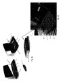
本発明に従う例示的な分注器1は、図1a、3a、および3bに例解される。医療デバイス3は、図3および4に示される。電極は、デバイス3の一体部分として提供される。それらは、デバイス3の底部に位置し、図4aで見ることができる。新しいゲルパッド2がデバイス3上に配設されることになっている時、それは、分注器1内のホルダ4内に配置される。図面中、分注器は、表示および制御ボタンを伴うデバイス3のための「スーツケース」の一部分である。追加のホルダ4’は、バッテリ駆動デバイス3を充電するために提供される。図1aで見られるように、トレー10は、デバイス1の左側において開放している。トレー10は、保護シート7の層間に挟持される接着要素2(ゲルパッド)の積み重ね体6を収容する。保護シート7は、バンドを形成し、2つの隣接するゲルパッドは、シート7が、2つのゲルパッド間で折り畳まれる7’ため、保護シートの2つの層によって分離される。結果として、保護シート7は、片側のみから引っ張ることによって、積み重ね体6内の最上部のゲルパッドから解放することができる。保護シート7は、円筒形のリール8の形態の牽引要素に接続される。このため、リール8を回転させることによって、シート7を引っ張ることができる。積み重ね体6の下に位置するバネ5の形態の弾性要素。(圧縮された)バネ5は、図1bで見られるように、積み重ね体6をデバイス3に向かって付勢する。リール8が回転させられる時、シート7は、最上部のゲルパッド2から解放され、バネの圧縮力は、接着ゲルパッド2をデバイス3に向かって付勢して、ゲルパッド2とデバイス3との間に接着結合を形成する。
An
牽引要素8は、スイッチ9のための摺動通路9’が見える図3bでもっともはっきりと見られるように、この場合、摺動可能なボタン9の形態のスイッチによって、起動される。スイッチ9と牽引要素との間の係合は、図2に例解され、ここで、円筒形のホイール8には、2つの端部において、歯付きホイール11が提供される。スイッチ9には、歯付きホイール11に係合するように適応される、2つのラック12が提供される。スイッチ9が通路9’内でスリットされる時、ラック12は、歯付きホイール11に係合して、リールを回転させ、ゲルパッド2から保護シート7を解放する。この摺動可能なスイッチ9では、即ち、電気エネルギーを必要とすることなく、シート7を解放し、ゲルパッド2をデバイス3に結合させるのは、ユーザによって誘導される動きである。分注器1は、スイッチ9での単一の前後摺動が、最上部のゲルパッド2から保護シート7を解放するように、適応される。牽引要素は、スイッチ9が開始位置にスリットし戻される時、歯付きホイール11が、惰性回転する、即ち、リール8を回転させることなく惰性回転することができるように、適応され得る。または、スイッチ9は、例えば、歯付きホイール11に対するラック12の位置をわずかに調節することによって、開始位置に戻る時、ラック12が歯付きホイール11を係脱するように、適応され得る。
The
このトレー10は、交換可能または使い捨てまたは再充填可能であり得る。このため、ゲルパッドの積み重ね体全体が使用された時、トレー10は、退縮され、新たなトレーで交換され、ここに、ゲルパッドの新しい積み重ね体が配設される。
The
図1及び2の積み重ね体内の接着要素は、両面接着性である。しかしながら、図4aおよび4bに例解されるように、医療デバイス3’と接着要素2’との間の取設は、取設機構手段、この場合は、3つの金属スナップロック13、14によって、提供され得る。スナップロックの突出する部分14は、図4において、接着要素2’上に位置するが、しかしながら、それは、医療デバイス上に適切に位置してもよい。医療デバイス3’上のスナップロック部分13もまた、医療デバイスの電極を形成する。図4からも見られるように、スナップロック13、14の幾何学的構成は、医療デバイス3’に対する接着要素2’の正しい配置を確実にする。スナップロックは、部分13、14間の接続を失うことなく、個体の皮膚の湾曲に少なくとも部分的に追従するように、接着要素2’がわずかに屈曲(凸または凹)することができるように、溝部分13の内側の突出する部分14のある移動を可能にするように構成され得ることが、図4からさらに見ることができる。
本発明のさらなる詳細
The adhesive elements in the stack of FIGS. 1 and 2 are double-sided adhesive. However, as illustrated in FIGS. 4 a and 4 b, the installation between the
Further details of the invention
ここで、以下の項目を参照して、本発明をさらに詳細に説明する。
1.医療デバイス上に接着要素を配設するための分注器であって、
−前記医療デバイスを受容するように適応されるホルダと、
−前記接着要素の積み重ね体および弾性要素を備える、送達機構であって、前記積み重ね体は、接着要素の前記積み重ね体が前記ホルダに向かって押圧されるように、前記弾性要素上に配設され、前記接着要素の各々は、取り外し可能な保護シートの層間に配設される、送達機構と、
−前記取り外し可能な保護シートに接続される牽引要素、および前記牽引要素を動作させるために適応されるスイッチを備える、牽引機構であって、前記スイッチの起動時に、前記取り外し可能な保護シートを引っ張るために適応される、牽引機構と、を備える、分注器。
2.前記牽引機構は、好ましくは、前記スイッチの起動時に、接着要素の少なくとも片側から前記保護シートを解放するために適応される、項目1に記載の分注器。
3.前記牽引機構は、好ましくは、前記スイッチの起動時に、前記積み重ね体内の最上部の接着要素の少なくとも片側から前記保護シートを解放するために適応される、先行項目のいずれかに記載の分注器。
4.前記スイッチは、前記牽引要素に係合するように適応される、先行項目のいずれかに記載の分注器。
5.前記スイッチは、前記牽引要素に機械的に係合する、先行項目のいずれかに記載の分注器。
6.前記スイッチは、前記牽引要素に係合するように適応される1つ以上のラックを備える、先行項目のいずれかに記載の分注器。
7.前記牽引要素は、前記保護シートを巻くための円筒形のリールを備える、先行項目のいずれかに記載の分注器。
8.前記牽引要素は、1つ以上の歯付きホイールを備える、先行項目のいずれかに記載の分注器。
9.前記1つ以上の歯付きホイールは、1つの回転方向において、惰性回転するように適応される、項目8に記載の分注器。
10.前記スイッチは、摺動可能なボタンを備え、前記スイッチの起動は、前記摺動可能なボタンを摺動させることを含む、先行項目のいずれかに記載の分注器。
11.前記スイッチの起動は、前記摺動可能なボタンでの単一の摺動に対応する、項目10に記載の分注器。
12.前記スイッチの起動は、前記摺動可能なボタンでの2つ以上の摺動に対応する、項目10に記載の分注器。
13.前記スイッチの起動は、前記摺動可能なボタンでの前後摺動に対応する、項目10に記載の分注器。
14.前記スイッチは、前記摺動ボタンの1つの摺動方向のみに対して、牽引要素に係合するように適応される、項目10〜13のいずれかに記載の分注器。
15.前記牽引機構は、弾性スイッチ解放をさらに備える、先行項目のいずれかに記載の分注器。
16.前記弾性スイッチ解放は、前記スイッチの起動後、前記スイッチを開始点に戻すように適応される、項目15に記載の分注器。
17.前記牽引機構は、手動で動作される、先行項目のいずれかに記載の分注器。
18.前記牽引機構は、電子的である、先行項目のいずれかに記載の分注器。
19.前記牽引機構は、前記牽引要素を駆動するためのモータまたはアクチュエータを備える、先行項目のいずれかに記載の分注器。
20.前記接着要素の積み重ね体は、前記ホルダに隣接して位置する、先行項目のいずれかに記載の分注器。
21.前記接着要素の積み重ね体は、前記ホルダの下に垂直に位置するといった、垂直に配設される、先行項目のいずれかに記載の分注器。
22.前記接着要素の積み重ね体は、前記ホルダに隣接して水平に位置するといった、水平に配設される、先行項目のいずれかに記載の分注器。
23.前記接着要素の積み重ね体は、前記保護シートの層間に挟持される接着要素から形成される、先行項目のいずれかに記載の分注器。
24.前記接着要素は、正確に前記積み重ね体内の互いの上部に配設される、先行項目のいずれかに記載の分注器。
25.前記接着要素は、前記積み重ね体内で互いに対して変位される、先行項目のいずれかに記載の分注器。
26.前記保護シートは、バンドを形成する、先行項目のいずれかに記載の分注器。
27.前記接着要素の各々は、保護シートの2つの層間に配設される、項目26に記載の分注器。
28.前記接着要素の各々は、保護シートの2つの層間に配設され、前記2つの層は、保護シートの単一の層を折り畳むことによって形成される、項目26に記載の分注器。
29.前記接着要素の積み重ね体は、前記保護シートのバンドが、前記積み重ね体の片側のみから前記バンドを引っ張ることによって、最上部または最外部の接着要素から解放され得るように、形成される、先行項目26〜28のいずれかに記載の分注器。
30.前記弾性要素は、1つ以上のバネを備える、先行項目のいずれかに記載の分注器。
31.前記分注器は、前記医療デバイスにおける既定の位置に、前記接着要素を自動的にまたは少なくとも半自動的に配設するように適応される、先行項目のいずれかに記載の分注器。
32.前記医療デバイスは、ユーザの皮膚上に配設されるように適応される電極アセンブリである、先行項目のいずれかに記載の分注器。
33.前記接着要素は、前記医療デバイスの電極アセンブリ上に配設される、先行項目のいずれかに記載の分注器。
34.前記分注器は、前記医療デバイスにおける既定の位置に、前記接着要素を自動的にまたは少なくとも半自動的に配設するように適応される、先行項目のいずれかに記載の分注器。
35.前記医療デバイスは、ユーザの皮膚上に配設されるように適応される電極アセンブリである、先行項目のいずれかに記載の分注器。
36.前記接着要素は、前記医療デバイスの電極アセンブリ上に配設される、先行項目のいずれかに記載の分注器。
37.前記医療デバイスは、前記分注器の一部分である、先行項目のいずれかに記載の分注器。
38.医療デバイス上に配設されるように適応される、接着要素。
39.前記接着要素は、両面接着性である、先行項目38のいずれかに記載の接着要素。
40.前記医療デバイス上の取設機構に整合するようにさらに適応される、先行項目38〜39のいずれかに記載の接着要素。
41.前記接着要素は、片側上で接着性であり、反対側上に、取設機構の一部分を備え、前記取設機構の前記部分は、前記医療デバイス上の取設機構の対応する部分に整合するように適応される、先行項目38〜40ののいずれかに記載の接着要素。
42.前記取設機構は、1つ、2つ、3つ、またはそれ以上のスナップロックである、項目41に記載の接着要素。
43.前記取設機構の前記部分は、前記医療デバイス上の前記取設機構の対応する構成要素に整合するように形状化される1つ以上の構成要素を備える、項目41〜42のいずれかに記載の接着要素。
44.前記構成要素の形状は、三角形、四角形、五角形、六角形、または星形状といった、多角形である、項目43に記載の接着要素。
45.前記取設機構は、フックおよびループファスナを備える、項目41〜44のいずれかに記載の接着要素。
46.前記取設機構は、1つ以上のクリップまたはクランプを備える、項目41〜45のいずれかに記載の接着要素。
47.前記取設機構は、少なくとも部分的に磁性である、項目41〜46のいずれかに記載の接着要素。
48.前記取設機構は、前記接着要素と前記医療デバイスとの間の電気接続を提供するように適応される、項目41〜47のいずれかに記載の接着要素。
49.前記接着要素は、使い捨てである、先行項目38〜48のいずれかに記載の接着要素。
50.前記接着要素は、ゲルパッドといったパッドである、先行項目38〜49のいずれかに記載の接着要素。
51.前記接着要素の形状は、前記医療デバイスの形状に整合する、先行項目38〜50のいずれかに記載の接着要素。
52.前記接着要素は、前記医療デバイスとユーザの皮膚との間の接着結合を形成するように適応される、先行項目38〜51のいずれかに記載の接着要素。
53.前記接着要素は、伝導性材料を備える、先行項目38〜52のいずれかに記載の接着要素。
54.前記接着要素は、可撓性および/または可屈曲性である、先行項目38〜53のいずれかに記載の接着要素。
55.前記取設機構は、前記取設機構の対応する部分間の適応された移動である、先行項目41〜54のいずれかに記載の接着要素。
56.前記取設機構は、移動が、前記取設機構によって提供される電気接続を維持するように、適応される、先行項目41〜55のいずれかに記載の接着要素。
57.前記取設機構は、接着要素を伴う前記医療デバイスが個体に適用される時、皮膚に実質的に垂直な方向において、移動が提供されるように、適応される、先行項目41〜56のいずれかに記載の接着要素。
58.前記接着要素は、前記医療デバイスとユーザの皮膚との間の伝導性接続を形成するように適応される、先行項目38〜57のいずれかに記載の接着要素。
59.前記接着要素(複数を含む)は、項目38〜58のいずれかに記載の接着要素(複数を含む)である、先行項目のいずれかに記載の分注器。
60.先行項目のいずれかに記載の分注器のためのトレーであって、弾性要素上に配設される接着要素の積み重ね体であって、前記接着要素は、保護シートの層間に配設される、積み重ね体と、前記保護シートに接続され、前記保護シートを引っ張るように適応される、牽引要素と、を備える、トレー。
61.前記トレーは、交換可能または使い捨てである、項目60に記載のトレー。
62.前記トレーは、先行項目のいずれかに記載される特性のうちのいずれかを備える、項目60〜61のいずれかに記載のトレー。
63.前記接着要素は、項目38〜58のいずれかによって定義される接着要素である、項目60〜62のいずれかに記載のトレー。
64.複数の電極を伴う電極アセンブリを備える、個体の筋肉活動を監視するための医療デバイスであって、前記電極アセンブリは、接着要素上の取設機構の対応する部分に整合するように適応される取設機構の一部分を備え、前記医療デバイスは、電気信号を受容および監視する、ならびに前記個体に電気刺激を提供するために適応される、医療デバイス。
65.前記医療デバイスは、歯ぎしりに関連する筋肉活動を監視するために好適であり、前記歯ぎしりを検出するために、前記受容された信号を処理するために適応され、前記電気刺激は、前記歯ぎしりの検出に応答して提供されるフィードバック信号である、項目64に記載の医療デバイス。
66.前記医療デバイス上の取設機構は、1つ以上のクリップまたはクランプを備える、先行項目64〜65のいずれかに記載の医療デバイス。
67.前記接着要素は、項目38〜58のいずれかによって定義される接着要素である、先行項目64〜66のいずれかに記載の医療デバイス。
68.前記取設機構手段によって互いに取設されるように適応される、項目64〜66のいずれかに記載の医療デバイスと、項目38〜58のいずれかによって定義される接着要素とを備える、キット。
69.医療デバイス上に使い捨て接着要素を配設するための方法であって、
a.先行項目のいずれかに記載の分注器の前記スイッチを起動し、それによって、前記積み重ね体内の最上部の接着要素の片側から前記保護シートを解放するステップと、
b.前記分注器のホルダ内に前記医療デバイスを配設するステップであって、前記最上部の接着要素が、それによって、前記医療デバイスに取設される、ステップと、
c.前記分注器から前記接着要素を伴う前記医療デバイスを取り外すステップと、を含む、方法。
70.医療デバイス上に使い捨て接着要素を配設するための方法であって、
a.先行項目のいずれかに記載の分注器の前記ホルダ内に前記医療デバイスを配設するステップと、
b.前記スイッチを起動し、それによって、前記医療デバイスに面する前記積み重ね体内の最上部の接着要素の側から前記保護シートを解放するステップであって、前記最上部の接着要素が、それによって、前記医療デバイスに取設される、ステップと、
c.前記分注器から前記接着要素を伴う前記医療デバイスを取り外すステップと、を含む、方法。
The present invention will now be described in further detail with reference to the following items.
1. A dispenser for disposing an adhesive element on a medical device,
A holder adapted to receive the medical device;
A delivery mechanism comprising a stack of adhesive elements and an elastic element, the stack being arranged on the elastic elements such that the stack of adhesive elements is pressed against the holder Each of the adhesive elements is disposed between layers of a removable protective sheet; and a delivery mechanism;
A traction mechanism comprising a traction element connected to the removable protective sheet and a switch adapted to operate the traction element, the pulling of the removable protective sheet upon activation of the switch A dispenser adapted for, comprising a traction mechanism.
2.
3. A dispenser according to any preceding item, wherein the traction mechanism is preferably adapted to release the protective sheet from at least one side of the uppermost adhesive element in the stack upon activation of the switch. .
4). A dispenser according to any preceding item, wherein the switch is adapted to engage the traction element.
5. A dispenser according to any preceding item, wherein the switch mechanically engages the traction element.
6). A dispenser according to any preceding item, wherein the switch comprises one or more racks adapted to engage the traction element.
7). The dispenser according to any of the preceding items, wherein the traction element comprises a cylindrical reel for winding the protective sheet.
8). A dispenser according to any preceding item, wherein the traction element comprises one or more toothed wheels.
9. 9. A dispenser according to
10. The dispenser according to any of the preceding items, wherein the switch comprises a slidable button, and activation of the switch includes sliding the slidable button.
11. 11. A dispenser according to
12 Item 11. The dispenser of
13. Item 11. The dispenser according to
14 14. A dispenser according to any of items 10-13, wherein the switch is adapted to engage a traction element for only one sliding direction of the sliding button.
15. The dispenser of any preceding item, wherein the traction mechanism further comprises an elastic switch release.
16. 16. A dispenser according to item 15, wherein the elastic switch release is adapted to return the switch to a starting point after activation of the switch.
17. A dispenser according to any of the preceding items, wherein the traction mechanism is manually operated.
18. A dispenser according to any preceding item, wherein the traction mechanism is electronic.
19. The dispenser according to any of the preceding items, wherein the traction mechanism comprises a motor or actuator for driving the traction element.
20. The dispenser according to any of the preceding items, wherein the stack of adhesive elements is located adjacent to the holder.
21. A dispenser according to any preceding item, wherein the stack of adhesive elements is disposed vertically, such as vertically positioned under the holder.
22. The dispenser according to any of the preceding items, wherein the stack of adhesive elements is disposed horizontally, such as positioned horizontally adjacent to the holder.
23. The dispenser according to any one of the preceding items, wherein the stack of adhesive elements is formed from adhesive elements that are sandwiched between layers of the protective sheet.
24. A dispenser according to any preceding item, wherein the adhesive elements are arranged exactly on top of each other in the stack.
25. A dispenser according to any preceding item, wherein the adhesive elements are displaced relative to each other within the stack.
26. The dispenser according to any one of the preceding items, wherein the protective sheet forms a band.
27. 27. A dispenser according to item 26, wherein each of the adhesive elements is disposed between two layers of a protective sheet.
28. 27. A dispenser according to item 26, wherein each of the adhesive elements is disposed between two layers of a protective sheet, the two layers being formed by folding a single layer of the protective sheet.
29. The stack of adhesive elements is formed such that the band of the protective sheet can be released from the uppermost or outermost adhesive element by pulling the band from only one side of the stack. The dispenser according to any one of 26 to 28.
30. A dispenser according to any preceding item, wherein the elastic element comprises one or more springs.
31. A dispenser according to any preceding item, wherein the dispenser is adapted to automatically or at least semi-automatically dispose the adhesive element at a predetermined position on the medical device.
32. The dispenser of any preceding item, wherein the medical device is an electrode assembly adapted to be disposed on a user's skin.
33. The dispenser of any preceding item, wherein the adhesive element is disposed on an electrode assembly of the medical device.
34. A dispenser according to any preceding item, wherein the dispenser is adapted to automatically or at least semi-automatically dispose the adhesive element at a predetermined position on the medical device.
35. The dispenser of any preceding item, wherein the medical device is an electrode assembly adapted to be disposed on a user's skin.
36. The dispenser of any preceding item, wherein the adhesive element is disposed on an electrode assembly of the medical device.
37. A dispenser according to any preceding item, wherein the medical device is part of the dispenser.
38. An adhesive element adapted to be disposed on a medical device.
39. 39. Adhesive element according to any of the preceding items 38, wherein the adhesive element is double-sided adhesive.
40. 40. Adhesive element according to any of the preceding items 38-39, further adapted to match an installation mechanism on the medical device.
41. The adhesive element is adhesive on one side and comprises a portion of a mounting mechanism on the opposite side, the portion of the mounting mechanism aligning with a corresponding portion of the mounting mechanism on the medical device 41. Adhesive element according to any of the preceding items 38-40, adapted as follows.
42. 42. The adhesive element of item 41, wherein the attachment mechanism is one, two, three, or more snap locks.
43. 43. Any of items 41-42, wherein the portion of the mounting mechanism comprises one or more components that are shaped to align with corresponding components of the mounting mechanism on the medical device. Adhesive elements.
44. 44. The adhesive element according to item 43, wherein the shape of the component is a polygon such as a triangle, a quadrangle, a pentagon, a hexagon, or a star.
45. 45. An adhesive element according to any of items 41 to 44, wherein the installation mechanism comprises a hook and a loop fastener.
46. 46. Adhesive element according to any of items 41-45, wherein the mounting mechanism comprises one or more clips or clamps.
47. 47. An adhesive element according to any of items 41 to 46, wherein the installation mechanism is at least partially magnetic.
48. 48. The adhesive element according to any of items 41-47, wherein the mounting mechanism is adapted to provide an electrical connection between the adhesive element and the medical device.
49. 49. Adhesive element according to any of the preceding items 38-48, wherein the adhesive element is disposable.
50. The adhesive element according to any one of the preceding items 38 to 49, wherein the adhesive element is a pad such as a gel pad.
51. 51. An adhesive element according to any of the preceding items 38-50, wherein the shape of the adhesive element matches the shape of the medical device.
52. 52. The adhesive element according to any of the preceding items 38-51, wherein the adhesive element is adapted to form an adhesive bond between the medical device and a user's skin.
53. 53. The adhesive element according to any of the preceding items 38-52, wherein the adhesive element comprises a conductive material.
54. 54. Adhesive element according to any of the preceding items 38 to 53, wherein the adhesive element is flexible and / or bendable.
55. 55. Adhesive element according to any of the preceding items 41 to 54, wherein the installation mechanism is an adapted movement between corresponding parts of the installation mechanism.
56. 56. Adhesive element according to any of the preceding items 41-55, wherein the mounting mechanism is adapted so that movement maintains the electrical connection provided by the mounting mechanism.
57. Any of the preceding items 41-56, wherein the attachment mechanism is adapted to provide movement in a direction substantially perpendicular to the skin when the medical device with an adhesive element is applied to an individual. The adhesive element according to crab.
58. 58. The adhesive element according to any of the preceding items 38-57, wherein the adhesive element is adapted to form a conductive connection between the medical device and a user's skin.
59. 59. A dispenser according to any of the preceding items, wherein the adhesive element (including a plurality) is an adhesive element (including a plurality) according to any of items 38-58.
60. A tray for a dispenser according to any of the preceding items, which is a stack of adhesive elements disposed on an elastic element, the adhesive elements being disposed between layers of a protective sheet A tray comprising a stack and a traction element connected to the protective sheet and adapted to pull the protective sheet.
61. 61. A tray according to item 60, wherein the tray is replaceable or disposable.
62. 62. A tray according to any of items 60-61, wherein the tray comprises any of the properties described in any of the preceding items.
63. 63. A tray according to any of items 60-62, wherein the adhesive element is an adhesive element defined by any of items 38-58.
64. A medical device for monitoring an individual's muscle activity comprising an electrode assembly with a plurality of electrodes, wherein the electrode assembly is adapted to align with a corresponding portion of a mounting mechanism on an adhesive element. A medical device comprising a portion of an installation mechanism, wherein the medical device is adapted to receive and monitor electrical signals and to provide electrical stimulation to the individual.
65. The medical device is suitable for monitoring muscle activity associated with bruxism and is adapted to process the received signal to detect the bruxism, wherein the electrical stimulation is used to detect the bruxism. 65. The medical device of item 64, wherein the medical device is a feedback signal provided in response to.
66. The medical device according to any of the preceding items 64-65, wherein the mounting mechanism on the medical device comprises one or more clips or clamps.
67. 67. The medical device according to any of the preceding items 64-66, wherein the adhesive element is an adhesive element defined by any of items 38-58.
68. 69. A kit comprising a medical device according to any of items 64-66 and an adhesive element defined by any of items 38-58 adapted to be attached to each other by said attachment mechanism means.
69. A method for disposing a disposable adhesive element on a medical device comprising:
a. Activating the switch of the dispenser according to any of the preceding items, thereby releasing the protective sheet from one side of the uppermost adhesive element in the stack;
b. Disposing the medical device in a holder of the dispenser, wherein the topmost adhesive element is thereby attached to the medical device;
c. Removing the medical device with the adhesive element from the dispenser.
70. A method for disposing a disposable adhesive element on a medical device comprising:
a. Disposing the medical device in the holder of the dispenser according to any of the preceding items;
b. Activating the switch, thereby releasing the protective sheet from the side of the uppermost adhesive element in the stack facing the medical device, the uppermost adhesive element thereby A step attached to a medical device;
c. Removing the medical device with the adhesive element from the dispenser.
Claims (40)
−前記医療デバイスを受容するように適応されるホルダと、
−前記接着要素の積み重ね体および弾性要素を備える、送達機構であって、前記積み重ね体は、接着要素の前記積み重ね体が前記ホルダに向かって押圧されるように、前記弾性要素上に配設され、前記接着要素の各々は、取り外し可能な保護シートの層間に配設される、送達機構と、
−前記取り外し可能な保護シートに接続される牽引要素、および前記牽引要素を動作させるために適応されるスイッチを備える、牽引機構であって、前記スイッチの起動時に、前記取り外し可能な保護シートを引っ張るために適応される、牽引機構と、を備える、分注器。 A dispenser for disposing an adhesive element on a medical device,
A holder adapted to receive the medical device;
A delivery mechanism comprising a stack of adhesive elements and an elastic element, the stack being arranged on the elastic elements such that the stack of adhesive elements is pressed against the holder Each of the adhesive elements is disposed between layers of a removable protective sheet; and a delivery mechanism;
A traction mechanism comprising a traction element connected to the removable protective sheet and a switch adapted to operate the traction element, the pulling of the removable protective sheet upon activation of the switch A dispenser adapted for, comprising a traction mechanism.
a.先行請求項のいずれかに記載の分注器の前記スイッチを起動し、それによって、前記積み重ね体内の最上部の接着要素の片側から前記保護シートを解放するステップと、
b.前記分注器のホルダ内に前記医療デバイスを配設するステップであって、前記最上部の接着要素が、それによって、前記医療デバイスに取設される、ステップと、
c.前記分注器から前記接着要素を伴う前記医療デバイスを取り外すステップと、を含む、方法。 A method for disposing a disposable adhesive element on a medical device comprising:
a. Activating the switch of the dispenser according to any of the preceding claims, thereby releasing the protective sheet from one side of the uppermost adhesive element in the stack;
b. Disposing the medical device in a holder of the dispenser, wherein the topmost adhesive element is thereby attached to the medical device;
c. Removing the medical device with the adhesive element from the dispenser.
a.先行請求項のいずれかに記載の分注器の前記ホルダ内に前記医療デバイスを配設するステップと、
b.前記スイッチを起動し、それによって、前記医療デバイスに面する前記積み重ね体内の最上部の接着要素の側から前記保護シートを解放するステップであって、前記最上部の接着要素が、それによって、前記医療デバイスに取設される、ステップと、
c.前記分注器から前記接着要素を伴う前記医療デバイスを取り外すステップと、を含む、方法。 A method for disposing a disposable adhesive element on a medical device comprising:
a. Disposing the medical device in the holder of a dispenser according to any of the preceding claims;
b. Activating the switch, thereby releasing the protective sheet from the side of the uppermost adhesive element in the stack facing the medical device, the uppermost adhesive element thereby A step attached to a medical device;
c. Removing the medical device with the adhesive element from the dispenser.
Applications Claiming Priority (3)
| Application Number | Priority Date | Filing Date | Title |
|---|---|---|---|
| US201261666035P | 2012-06-29 | 2012-06-29 | |
| US61/666,035 | 2012-06-29 | ||
| PCT/EP2013/063663 WO2014001520A1 (en) | 2012-06-29 | 2013-06-28 | Gel pad dispenser |
Publications (2)
| Publication Number | Publication Date |
|---|---|
| JP2015521514A true JP2015521514A (en) | 2015-07-30 |
| JP2015521514A5 JP2015521514A5 (en) | 2016-07-21 |
Family
ID=48783204
Family Applications (1)
| Application Number | Title | Priority Date | Filing Date |
|---|---|---|---|
| JP2015519137A Pending JP2015521514A (en) | 2012-06-29 | 2013-06-28 | Gel pad dispenser |
Country Status (6)
| Country | Link |
|---|---|
| US (1) | US20150174392A1 (en) |
| EP (1) | EP2866648A1 (en) |
| JP (1) | JP2015521514A (en) |
| CN (1) | CN104427933A (en) |
| SG (2) | SG11201408382RA (en) |
| WO (1) | WO2014001520A1 (en) |
Families Citing this family (4)
| Publication number | Priority date | Publication date | Assignee | Title |
|---|---|---|---|---|
| US10998092B2 (en) * | 2013-11-14 | 2021-05-04 | Mores, Inc. | Dispenser apparatus |
| ES2765195T3 (en) * | 2015-06-30 | 2020-06-08 | Sunstar Suisse Sa | Disposable adhesive substrate adapted for disposal in a medical device |
| TWI555509B (en) * | 2015-11-10 | 2016-11-01 | 鋐雩科技有限公司 | Electrode device for wearable or portable apparatus |
| US20170225202A1 (en) * | 2016-02-05 | 2017-08-10 | Hirouye Teshome | Fast, Convenient and Efficient Alternate Method to the Use of Prep Pad Soaked With a Variety of Solutions. |
Citations (8)
| Publication number | Priority date | Publication date | Assignee | Title |
|---|---|---|---|---|
| US4051842A (en) * | 1975-09-15 | 1977-10-04 | International Medical Corporation | Electrode and interfacing pad for electrical physiological systems |
| US4635642A (en) * | 1985-07-18 | 1987-01-13 | American Hospital Supply Corporation | Medical electrode with reusable conductor |
| US4669477A (en) * | 1985-05-20 | 1987-06-02 | Empi, Inc. | Apparatus and method for preventing bruxism |
| JPH0866482A (en) * | 1994-08-31 | 1996-03-12 | Sharp Corp | Electrode conductor of low-frequency curative device and its manufacturing method |
| JP2004024320A (en) * | 2002-06-21 | 2004-01-29 | Advanced Medical Kk | Biomedical electrode |
| US20080114220A1 (en) * | 2006-11-10 | 2008-05-15 | Triage Wireless, Inc. | Two-part patch sensor for monitoring vital signs |
| JP2011194231A (en) * | 2010-03-18 | 2011-10-06 | Tyco Healthcare Group Lp | Electrode delivery system |
| US20120108920A1 (en) * | 2007-09-14 | 2012-05-03 | Corventis, Inc. | Adherent device with multiple physiological sensors |
Family Cites Families (15)
| Publication number | Priority date | Publication date | Assignee | Title |
|---|---|---|---|---|
| FR2750685B1 (en) * | 1996-07-05 | 1998-10-16 | Smartech | TAPE BOX FOR TAPE, ESPECIALLY FOR ADHESIVE TAPE |
| US6898465B2 (en) * | 2001-10-17 | 2005-05-24 | The Ludlow Company Ip | Differential gel body for a medical stimulation electrode |
| JP4809212B2 (en) * | 2003-04-01 | 2011-11-09 | メドテック エイ/エス | Method and apparatus for monitoring muscle activity |
| CN1810319A (en) * | 2005-01-25 | 2006-08-02 | 电子科技大学 | Electromechanical bruxism monitoring and treating equipment |
| EP2144559A4 (en) * | 2007-05-07 | 2012-07-25 | Cardiac Lead Technologies Llc | Electrocardiograph monitoring device and connector |
| WO2009015074A1 (en) | 2007-07-20 | 2009-01-29 | Ropheka Technologies, Inc. | Devices for applying conductive gel-pads to electrodes and electrodes produced thereby |
| EP2200510B1 (en) | 2007-09-21 | 2011-12-28 | Medotech A/S | Electrode assemblies and bruxism monitoring apparatus |
| CN101902960B (en) | 2007-09-21 | 2013-11-06 | 太阳星瑞士有限公司 | Electrode connection monitoring |
| GB0810843D0 (en) * | 2008-06-13 | 2008-07-23 | Monica Healthcare Ltd | Electrode and electrode positioning arrangement for abdominal fetal electrocardiogram detection |
| US9014778B2 (en) * | 2008-06-24 | 2015-04-21 | Biosense Webster, Inc. | Disposable patch and reusable sensor assembly for use in medical device localization and mapping systems |
| US9737225B2 (en) * | 2008-06-24 | 2017-08-22 | Biosense Webster, Inc. | Patch and sensor assembly for use in medical device localization and mapping systems |
| CN201308557Y (en) * | 2008-12-02 | 2009-09-16 | 南通同润生物科技有限公司 | Biofeedback bruxism therapy device |
| BRPI0805365A2 (en) * | 2008-12-19 | 2011-10-18 | Timpel S.A. | electrode system for transdermal conduction of electrical signals, and method of use |
| CN201642503U (en) * | 2010-03-11 | 2010-11-24 | 南方医科大学 | Monitoring treatment device based on biofeedback |
| US20120089000A1 (en) * | 2010-10-08 | 2012-04-12 | Jon Mikalson Bishay | Ambulatory Electrocardiographic Monitor For Providing Ease Of Use In Women And Method Of Use |
-
2013
- 2013-06-28 EP EP13736513.6A patent/EP2866648A1/en not_active Withdrawn
- 2013-06-28 JP JP2015519137A patent/JP2015521514A/en active Pending
- 2013-06-28 US US14/410,678 patent/US20150174392A1/en not_active Abandoned
- 2013-06-28 CN CN201380036935.9A patent/CN104427933A/en active Pending
- 2013-06-28 SG SG11201408382RA patent/SG11201408382RA/en unknown
- 2013-06-28 WO PCT/EP2013/063663 patent/WO2014001520A1/en active Application Filing
- 2013-06-28 SG SG10201610941VA patent/SG10201610941VA/en unknown
Patent Citations (8)
| Publication number | Priority date | Publication date | Assignee | Title |
|---|---|---|---|---|
| US4051842A (en) * | 1975-09-15 | 1977-10-04 | International Medical Corporation | Electrode and interfacing pad for electrical physiological systems |
| US4669477A (en) * | 1985-05-20 | 1987-06-02 | Empi, Inc. | Apparatus and method for preventing bruxism |
| US4635642A (en) * | 1985-07-18 | 1987-01-13 | American Hospital Supply Corporation | Medical electrode with reusable conductor |
| JPH0866482A (en) * | 1994-08-31 | 1996-03-12 | Sharp Corp | Electrode conductor of low-frequency curative device and its manufacturing method |
| JP2004024320A (en) * | 2002-06-21 | 2004-01-29 | Advanced Medical Kk | Biomedical electrode |
| US20080114220A1 (en) * | 2006-11-10 | 2008-05-15 | Triage Wireless, Inc. | Two-part patch sensor for monitoring vital signs |
| US20120108920A1 (en) * | 2007-09-14 | 2012-05-03 | Corventis, Inc. | Adherent device with multiple physiological sensors |
| JP2011194231A (en) * | 2010-03-18 | 2011-10-06 | Tyco Healthcare Group Lp | Electrode delivery system |
Also Published As
| Publication number | Publication date |
|---|---|
| EP2866648A1 (en) | 2015-05-06 |
| US20150174392A1 (en) | 2015-06-25 |
| WO2014001520A1 (en) | 2014-01-03 |
| SG10201610941VA (en) | 2017-02-27 |
| CN104427933A (en) | 2015-03-18 |
| SG11201408382RA (en) | 2015-01-29 |
Similar Documents
| Publication | Publication Date | Title |
|---|---|---|
| US11185709B2 (en) | External defibrillator | |
| JP2015521514A (en) | Gel pad dispenser | |
| US10279201B2 (en) | Monitoring and treating pain with epidermal electronics | |
| JP2015521514A5 (en) | ||
| US20170136264A1 (en) | Monitoring and treating pain with epidermal electronics | |
| US20240149052A1 (en) | Adhesively coupled wearable medical device | |
| KR101473433B1 (en) | Patch device | |
| WO2009104765A1 (en) | Puncture tool with mechanism for relieving needle puncture pain and tool for relieving needle puncture pain | |
| WO2019130961A1 (en) | Blood pressure measurement apparatus | |
| JP2013542032A (en) | Carrying case for accessories including defibrillator and CPR meter bracket | |
| JP2014504522A5 (en) | ||
| WO2010033819A1 (en) | Pyro/piezo sensor and stimulator | |
| WO2014071915A3 (en) | Device for a controlled heart-lung resuscitation in the event of a cardiac arrest | |
| JP2006218109A (en) | Sticking material for hemostasis | |
| US20120310123A1 (en) | Device and method for controlled heart-lung-reanimation when the heart stops | |
| CN107714093B (en) | A kind of percussion hammer for Neurology | |
| JP6410506B2 (en) | Breathing apparatus | |
| JP2020173169A (en) | Circumference measuring device and capacitance type sensor element | |
| KR101843291B1 (en) | Device for pressing heart | |
| JP2020086959A (en) | Operation support device and operation support method | |
| JP2013537135A (en) | Seat belt pressure relief device with adjustable tightening length | |
| JP6896609B2 (en) | Blood pressure measuring device | |
| EP4362773A1 (en) | A flexible and stretchable cover for attaching a component to a patch | |
| CN203634665U (en) | Tensioning and retaining device and ultrasonic therapeutic device | |
| KR101545549B1 (en) | Self treatment device compresses |
Legal Events
| Date | Code | Title | Description |
|---|---|---|---|
| A524 | Written submission of copy of amendment under article 19 pct |
Free format text: JAPANESE INTERMEDIATE CODE: A524 Effective date: 20160531 |
|
| A621 | Written request for application examination |
Free format text: JAPANESE INTERMEDIATE CODE: A621 Effective date: 20160531 |
|
| A977 | Report on retrieval |
Free format text: JAPANESE INTERMEDIATE CODE: A971007 Effective date: 20170323 |
|
| A131 | Notification of reasons for refusal |
Free format text: JAPANESE INTERMEDIATE CODE: A131 Effective date: 20170331 |
|
| A601 | Written request for extension of time |
Free format text: JAPANESE INTERMEDIATE CODE: A601 Effective date: 20170501 |
|
| A521 | Request for written amendment filed |
Free format text: JAPANESE INTERMEDIATE CODE: A523 Effective date: 20170929 |
|
| A131 | Notification of reasons for refusal |
Free format text: JAPANESE INTERMEDIATE CODE: A131 Effective date: 20171227 |
|
| A601 | Written request for extension of time |
Free format text: JAPANESE INTERMEDIATE CODE: A601 Effective date: 20180306 |
|
| A02 | Decision of refusal |
Free format text: JAPANESE INTERMEDIATE CODE: A02 Effective date: 20181112 |