JP2015517373A - Magnetic resonance safe electrode for biopotential measurement - Google Patents
Magnetic resonance safe electrode for biopotential measurement Download PDFInfo
- Publication number
- JP2015517373A JP2015517373A JP2015513310A JP2015513310A JP2015517373A JP 2015517373 A JP2015517373 A JP 2015517373A JP 2015513310 A JP2015513310 A JP 2015513310A JP 2015513310 A JP2015513310 A JP 2015513310A JP 2015517373 A JP2015517373 A JP 2015517373A
- Authority
- JP
- Japan
- Prior art keywords
- electrode
- electrode patch
- conductive trace
- layer
- disposed
- Prior art date
- Legal status (The legal status is an assumption and is not a legal conclusion. Google has not performed a legal analysis and makes no representation as to the accuracy of the status listed.)
- Pending
Links
Images


Classifications
-
- A—HUMAN NECESSITIES
- A61—MEDICAL OR VETERINARY SCIENCE; HYGIENE
- A61B—DIAGNOSIS; SURGERY; IDENTIFICATION
- A61B5/00—Measuring for diagnostic purposes; Identification of persons
- A61B5/24—Detecting, measuring or recording bioelectric or biomagnetic signals of the body or parts thereof
- A61B5/25—Bioelectric electrodes therefor
- A61B5/279—Bioelectric electrodes therefor specially adapted for particular uses
- A61B5/28—Bioelectric electrodes therefor specially adapted for particular uses for electrocardiography [ECG]
- A61B5/282—Holders for multiple electrodes
-
- A—HUMAN NECESSITIES
- A61—MEDICAL OR VETERINARY SCIENCE; HYGIENE
- A61L—METHODS OR APPARATUS FOR STERILISING MATERIALS OR OBJECTS IN GENERAL; DISINFECTION, STERILISATION OR DEODORISATION OF AIR; CHEMICAL ASPECTS OF BANDAGES, DRESSINGS, ABSORBENT PADS OR SURGICAL ARTICLES; MATERIALS FOR BANDAGES, DRESSINGS, ABSORBENT PADS OR SURGICAL ARTICLES
- A61L31/00—Materials for other surgical articles, e.g. stents, stent-grafts, shunts, surgical drapes, guide wires, materials for adhesion prevention, occluding devices, surgical gloves, tissue fixation devices
- A61L31/14—Materials characterised by their function or physical properties, e.g. injectable or lubricating compositions, shape-memory materials, surface modified materials
- A61L31/18—Materials at least partially X-ray or laser opaque
-
- A—HUMAN NECESSITIES
- A61—MEDICAL OR VETERINARY SCIENCE; HYGIENE
- A61B—DIAGNOSIS; SURGERY; IDENTIFICATION
- A61B5/00—Measuring for diagnostic purposes; Identification of persons
- A61B5/24—Detecting, measuring or recording bioelectric or biomagnetic signals of the body or parts thereof
- A61B5/25—Bioelectric electrodes therefor
- A61B5/251—Means for maintaining electrode contact with the body
- A61B5/257—Means for maintaining electrode contact with the body using adhesive means, e.g. adhesive pads or tapes
- A61B5/259—Means for maintaining electrode contact with the body using adhesive means, e.g. adhesive pads or tapes using conductive adhesive means, e.g. gels
-
- A—HUMAN NECESSITIES
- A61—MEDICAL OR VETERINARY SCIENCE; HYGIENE
- A61B—DIAGNOSIS; SURGERY; IDENTIFICATION
- A61B5/00—Measuring for diagnostic purposes; Identification of persons
- A61B5/24—Detecting, measuring or recording bioelectric or biomagnetic signals of the body or parts thereof
- A61B5/25—Bioelectric electrodes therefor
- A61B5/279—Bioelectric electrodes therefor specially adapted for particular uses
- A61B5/291—Bioelectric electrodes therefor specially adapted for particular uses for electroencephalography [EEG]
-
- A—HUMAN NECESSITIES
- A61—MEDICAL OR VETERINARY SCIENCE; HYGIENE
- A61B—DIAGNOSIS; SURGERY; IDENTIFICATION
- A61B5/00—Measuring for diagnostic purposes; Identification of persons
- A61B5/24—Detecting, measuring or recording bioelectric or biomagnetic signals of the body or parts thereof
- A61B5/25—Bioelectric electrodes therefor
- A61B5/279—Bioelectric electrodes therefor specially adapted for particular uses
- A61B5/296—Bioelectric electrodes therefor specially adapted for particular uses for electromyography [EMG]
-
- A—HUMAN NECESSITIES
- A61—MEDICAL OR VETERINARY SCIENCE; HYGIENE
- A61L—METHODS OR APPARATUS FOR STERILISING MATERIALS OR OBJECTS IN GENERAL; DISINFECTION, STERILISATION OR DEODORISATION OF AIR; CHEMICAL ASPECTS OF BANDAGES, DRESSINGS, ABSORBENT PADS OR SURGICAL ARTICLES; MATERIALS FOR BANDAGES, DRESSINGS, ABSORBENT PADS OR SURGICAL ARTICLES
- A61L31/00—Materials for other surgical articles, e.g. stents, stent-grafts, shunts, surgical drapes, guide wires, materials for adhesion prevention, occluding devices, surgical gloves, tissue fixation devices
- A61L31/02—Inorganic materials
- A61L31/022—Metals or alloys
-
- G—PHYSICS
- G01—MEASURING; TESTING
- G01R—MEASURING ELECTRIC VARIABLES; MEASURING MAGNETIC VARIABLES
- G01R33/00—Arrangements or instruments for measuring magnetic variables
- G01R33/20—Arrangements or instruments for measuring magnetic variables involving magnetic resonance
- G01R33/28—Details of apparatus provided for in groups G01R33/44 - G01R33/64
- G01R33/32—Excitation or detection systems, e.g. using radio frequency signals
- G01R33/34—Constructional details, e.g. resonators, specially adapted to MR
- G01R33/34084—Constructional details, e.g. resonators, specially adapted to MR implantable coils or coils being geometrically adaptable to the sample, e.g. flexible coils or coils comprising mutually movable parts
-
- A—HUMAN NECESSITIES
- A61—MEDICAL OR VETERINARY SCIENCE; HYGIENE
- A61B—DIAGNOSIS; SURGERY; IDENTIFICATION
- A61B2562/00—Details of sensors; Constructional details of sensor housings or probes; Accessories for sensors
- A61B2562/02—Details of sensors specially adapted for in-vivo measurements
- A61B2562/0209—Special features of electrodes classified in A61B5/24, A61B5/25, A61B5/283, A61B5/291, A61B5/296, A61B5/053
- A61B2562/0215—Silver or silver chloride containing
-
- A—HUMAN NECESSITIES
- A61—MEDICAL OR VETERINARY SCIENCE; HYGIENE
- A61B—DIAGNOSIS; SURGERY; IDENTIFICATION
- A61B2562/00—Details of sensors; Constructional details of sensor housings or probes; Accessories for sensors
- A61B2562/12—Manufacturing methods specially adapted for producing sensors for in-vivo measurements
- A61B2562/125—Manufacturing methods specially adapted for producing sensors for in-vivo measurements characterised by the manufacture of electrodes
-
- A—HUMAN NECESSITIES
- A61—MEDICAL OR VETERINARY SCIENCE; HYGIENE
- A61B—DIAGNOSIS; SURGERY; IDENTIFICATION
- A61B5/00—Measuring for diagnostic purposes; Identification of persons
- A61B5/05—Detecting, measuring or recording for diagnosis by means of electric currents or magnetic fields; Measuring using microwaves or radio waves
- A61B5/055—Detecting, measuring or recording for diagnosis by means of electric currents or magnetic fields; Measuring using microwaves or radio waves involving electronic [EMR] or nuclear [NMR] magnetic resonance, e.g. magnetic resonance imaging
-
- A—HUMAN NECESSITIES
- A61—MEDICAL OR VETERINARY SCIENCE; HYGIENE
- A61N—ELECTROTHERAPY; MAGNETOTHERAPY; RADIATION THERAPY; ULTRASOUND THERAPY
- A61N1/00—Electrotherapy; Circuits therefor
- A61N1/02—Details
- A61N1/08—Arrangements or circuits for monitoring, protecting, controlling or indicating
- A61N1/086—Magnetic resonance imaging [MRI] compatible leads
Landscapes
- Health & Medical Sciences (AREA)
- Life Sciences & Earth Sciences (AREA)
- Physics & Mathematics (AREA)
- General Health & Medical Sciences (AREA)
- Animal Behavior & Ethology (AREA)
- Veterinary Medicine (AREA)
- Heart & Thoracic Surgery (AREA)
- Surgery (AREA)
- Public Health (AREA)
- Engineering & Computer Science (AREA)
- Molecular Biology (AREA)
- Medical Informatics (AREA)
- Biomedical Technology (AREA)
- Pathology (AREA)
- Biophysics (AREA)
- Cardiology (AREA)
- Vascular Medicine (AREA)
- Epidemiology (AREA)
- Chemical & Material Sciences (AREA)
- Optics & Photonics (AREA)
- Inorganic Chemistry (AREA)
- Condensed Matter Physics & Semiconductors (AREA)
- General Physics & Mathematics (AREA)
- Dispersion Chemistry (AREA)
- Magnetic Resonance Imaging Apparatus (AREA)
- Measurement And Recording Of Electrical Phenomena And Electrical Characteristics Of The Living Body (AREA)
Abstract
磁気共鳴MR環境における生体電位測定に用いられる電極パッチ34が、プラスチック又はポリマーシート32と、上記プラスチック又はポリマーシートに配置され、1ohm/square又はこれより高いシート抵抗を持つ導電性トレース58と、上記導電性トレースに配置され、人間の皮膚に取り付けられるように構成される電極30とを含む。いくつかの実施形態において、上記導電性トレースは、炭素ベースの導電性トレースである。この電極は、上記導電性トレースに配置される銀又は他の導電層と、上記銀又は他の導電層に配置される、例えば塩化銀ベースの電解質層といった電解質層又は他の接着材層を有することができる。An electrode patch 34 used for biopotential measurement in a magnetic resonance MR environment is a plastic or polymer sheet 32, a conductive trace 58 disposed on the plastic or polymer sheet and having a sheet resistance of 1 ohm / square or higher, and And an electrode 30 disposed on the conductive trace and configured to be attached to human skin. In some embodiments, the conductive trace is a carbon-based conductive trace. The electrode has a silver or other conductive layer disposed on the conductive trace and an electrolyte layer or other adhesive layer, such as a silver chloride based electrolyte layer, disposed on the silver or other conductive layer. be able to.
Description
本願は、センサ分野、測定分野、磁気共鳴分野、安全分野、心電図記録法(ECG)、筋電図記録法(EMG)、脳波記録法(EEG)、網膜電図記録法(ERG)等を含む生体電位測定分野、心臓ゲート制御を使用するゲート制御MR撮像分野等に関する。 This application includes sensor field, measurement field, magnetic resonance field, safety field, electrocardiogram recording method (ECG), electromyogram recording method (EMG), electroencephalogram recording method (EEG), electroretinogram recording method (ERG), etc. The present invention relates to the field of biopotential measurement, the field of gated MR imaging using cardiac gate control, and the like.
例えば心電計(ECG)、脳波計(EEG)及び類似する測定といった従来の生体電位測定において、電位は、皮膚に配置される電極により測定される。従来は、例えば銅線を用いた高い電気伝導度を持つケーブルが、監視電子機器に電極を接続するために使用される。 In conventional biopotential measurements such as electrocardiograph (ECG), electroencephalograph (EEG) and similar measurements, the potential is measured by electrodes placed on the skin. Conventionally, cables with high electrical conductivity, for example using copper wires, are used to connect the electrodes to the monitoring electronics.
対象物が磁気共鳴(MR)スキャナに配置される間に生体電位測定が実行されるとき、従来の高伝導率ケーブルは、高抵抗ケーブルにより置き換えられる。これは、MR環境において高伝導率ケーブルを配置することで生じる多数の問題を考慮してのことである。問題としては例えば、RFパルス及び/又は傾斜磁場によりもたらされる加熱、無線周波数干渉問題等を含む。MR環境におけるECG又は他の生体電位測定器具の使用は、多数の用途を持つ。例えば、ECG信号は、患者の状態を監視するために用いられることができ、及び/又は例えば撮像データ収集といった特定のイベントをトリガーする又はゲート制御するのに使用されることができる。このようにして実行される心臓ゲート制御は、心拍が原因による運動アーチファクトを減らすことができる。 When biopotential measurements are performed while an object is placed on a magnetic resonance (MR) scanner, conventional high conductivity cables are replaced by high resistance cables. This takes into account a number of problems arising from the placement of high conductivity cables in an MR environment. Problems include, for example, heating caused by RF pulses and / or gradient fields, radio frequency interference problems, and the like. The use of an ECG or other biopotential measurement instrument in an MR environment has numerous applications. For example, the ECG signal can be used to monitor a patient's condition and / or can be used to trigger or gate a specific event, eg, imaging data collection. Cardiac gating performed in this way can reduce motion artifacts due to heartbeats.
MR室では、MRI環境に関連付けられるRF加熱効果及び熱傷ハザードが原因で、分散された又は分離した高抵抗ケーブルが、ECG機能を持つMRI患者モニタに対して電極を接続するために用いられる。これらの高抵抗ケーブルは、高価で、患者に対する加熱の原因となる可能性があり、結果として熱傷のリスクが伴う。それらは、製造しにくく、誘導的なピックアップに苦しむ可能性があり、摩擦電気効果の影響を受けやすく、寄生静電容量に苦しむ可能性があり、及び患者の動きに敏感である。分離したリード線のルーティングは、ECGパフォーマンスにおける不一致及び不正確をもたらす可能性がある。 In the MR room, due to the RF heating effects and burn hazards associated with the MRI environment, distributed or separate high resistance cables are used to connect electrodes to MRI patient monitors with ECG functionality. These high resistance cables are expensive and can cause heating to the patient, resulting in the risk of burns. They are difficult to manufacture, can suffer from inductive pick-up, are susceptible to triboelectric effects, can suffer from parasitic capacitance, and are sensitive to patient movement. Separate lead routing can lead to inconsistencies and inaccuracies in ECG performance.
MRスキャナにより生成される無線周波数(RF)場は、ケーブルにおける電流又は「ホットスポット」を生成する可能性があり、これは、規制標準で許される温度を超える表面温度まで上昇させ、患者に不快さ又は熱傷ハザードをもたらす場合がある。MR傾斜磁場は、干渉を引き起こすことがあり、ECGケーブル及び接続点に電流を誘導する可能性もある。これは、可能性として誤った心拍読み出しを与える付加的な干渉波形成分を生成し、ECGのR波検出方式をあいまいなものにし、又はECG分析を他の態様で劣化させる。各電極位置でめっきしたスナップコネクタを使用するケーブルも、分離したワイヤ及びコネクタからなる再使用可能なケーブルに各使い捨ての電極を接続するという時間のかかる手作業をもたらす。 The radio frequency (RF) field generated by MR scanners can create currents or “hot spots” in the cable, which raises the surface temperature beyond that allowed by regulatory standards and is uncomfortable for the patient. Or may cause burn hazard. MR gradients can cause interference and can induce current in ECG cables and connection points. This creates additional interfering waveform components that can potentially give false heart rate readouts, obscure ECG R-wave detection schemes, or otherwise degrade ECG analysis. Cables using snap connectors plated at each electrode location also result in the time consuming manual task of connecting each disposable electrode to a reusable cable consisting of separate wires and connectors.
Tuccilloその他による米国出願公開第2006/0247509A1号は、MRIで使用されるケーブルを開示し、これは、MRスキャナにより生成される磁場に基づき運動に抵抗するよう構成される。Tuccilloその他によるケーブルは、複数の導電トレースが導電性炭素インクを用いて引かれる柔軟なカプトン基板で構築される。開示された実施態様では、炭素インクは、10ohm/sqの抵抗を持つ。一方、ケーブルは、長さ6フィートで、約330ohms/cmの分散されたインピーダンスを持つ。ケーブルの端は、一端でECG電極と他端でECGモニタと接続するための銅パッドを持つ拡張領域を含む。 U.S. Publication No. 2006/0247509 A1 by Tuccillo et al. Discloses a cable for use in MRI, which is configured to resist movement based on the magnetic field generated by the MR scanner. Tuccillo et al.'S cable is constructed with a flexible Kapton substrate in which multiple conductive traces are drawn using conductive carbon ink. In the disclosed embodiment, the carbon ink has a resistance of 10 ohm / sq. On the other hand, the cable is 6 feet long and has a distributed impedance of about 330 ohms / cm. The end of the cable includes an extension region with a copper pad for connection to an ECG electrode at one end and an ECG monitor at the other end.
生体電位測定に関する電極は、MR環境における問題点ももたらす。既知の電極は、銀塩化銀(Ag−AgCl)電極である。この種の電極は、電極のハーフセル電位によりつくられるDCオフセット電圧を減らし、接触インピーダンスを最小化するための努力において、MR互換のECG電極の構造においても使用される。患者に対する電解質インタフェースとして、ペースト又はゲルが使用される。Van Genderingenらによる「Carbon-Fiber Electrodes and Leads for Electrocardiography during MR Imaging」、Radiology vol. 171 no. 3 page 872 (1989)は、プラスチック補強された炭素繊維リードを持つ炭素繊維でできているECG電極(Carbo Cone RE-I、Sundstroem社、スウェーデン)で、編まれた金属リードを持つ従来のAg−AgClECG電極を交換することを開示する。それらは、従来のAg−AgCl電極/編まれた金属リードと比較して、炭素繊維電極が、画像を劣化させなかったこと、及び黒鉛でできている類似する導線と比較して、プラスチック補強によって、炭素繊維リードが曲げの影響を受けにくくなることをレポートする。 Electrodes for biopotential measurement also present problems in the MR environment. A known electrode is a silver-silver chloride (Ag-AgCl) electrode. This type of electrode is also used in the construction of MR compatible ECG electrodes in an effort to reduce the DC offset voltage created by the electrode half-cell potential and minimize contact impedance. A paste or gel is used as the electrolyte interface to the patient. Van Genderingen et al. “Carbon-Fiber Electrodes and Leads for Electrocardiography during MR Imaging”, Radiology vol. 171 no. 3 page 872 (1989) Carbo Cone RE-I, Sundstroem, Sweden) discloses replacing a conventional Ag-AgClECG electrode with knitted metal leads. They compared to conventional Ag-AgCl electrodes / woven metal leads that the carbon fiber electrode did not degrade the image, and by plastic reinforcement compared to similar conductors made of graphite. Report that carbon fiber leads are less susceptible to bending.
本願は、上述した限界及びその他を克服する改良された装置及び方法を想定する。 The present application contemplates an improved apparatus and method that overcomes the aforementioned limitations and others.
1つの態様によれば、磁気共鳴(MR)環境における生体電位測定に用いられる電極パッチが開示される。この電極パッチは、プラスチック又はポリマーシートと、上記プラスチック又はポリマーシートに配置され、1ohm/square又はこれより高いシート抵抗を持つ導電性トレースと、上記導電性トレースに配置され、人間の皮膚に取付けられるよう構成される電極とを有する。 According to one aspect, an electrode patch for use in biopotential measurement in a magnetic resonance (MR) environment is disclosed. The electrode patch is disposed on the plastic or polymer sheet, the plastic or polymer sheet, a conductive trace having a sheet resistance of 1 ohm / square or higher, and is disposed on the conductive trace and attached to a human skin. An electrode configured as described above.
別の態様によれば、磁気共鳴(MR)環境における生体電位測定に用いられる電極パッチが開示される。この電極パッチは、プラスチック又はポリマーシートと、上記プラスチック又はポリマーシートに配置される炭素ベースの導電性トレースと、上記導電性トレースに配置され、人間の皮膚に取付けられるよう構成される電極とを有する。 According to another aspect, an electrode patch for use in biopotential measurement in a magnetic resonance (MR) environment is disclosed. The electrode patch has a plastic or polymer sheet, a carbon-based conductive trace disposed on the plastic or polymer sheet, and an electrode disposed on the conductive trace and configured to be attached to human skin. .
別の態様によれば、生体電位測定装置が、開示され、この装置は、上述したいずれかの電極パッチと、生体電位測定を受信するよう構成されるモニタ又はレシーバユニットと、上記モニタ又はレシーバユニットと上記電極パッチの上記電極とを電気的に接続するケーブルとを有する。 According to another aspect, a biopotential measurement device is disclosed, the device comprising any of the electrode patches described above, a monitor or receiver unit configured to receive a biopotential measurement, and the monitor or receiver unit. And a cable for electrically connecting the electrode of the electrode patch.
別の態様によれば、システムが、開示され、このシステムは、磁気共鳴スキャナと、上述した生体電位測定装置とを有し、上記電極パッチが、上記磁気共鳴スキャナの検査領域に配置される。 According to another aspect, a system is disclosed that includes a magnetic resonance scanner and the biopotential measurement device described above, wherein the electrode patch is disposed in an examination region of the magnetic resonance scanner.
1つの利点は、渦電流に対する感受性が減らされた、ECG又は他の生体電位測定に関する磁気共鳴互換の電極パッチを提供することにある。 One advantage resides in providing a magnetic resonance compatible electrode patch for ECG or other biopotential measurements with reduced sensitivity to eddy currents.
別の利点は、干渉に対して堅牢な、ECG又は他の生体電位測定に関する磁気共鳴互換の電極パッチを提供することにある。 Another advantage resides in providing a magnetic resonance compatible electrode patch for ECG or other biopotential measurements that is robust to interference.
別の利点は、人間の皮膚に対して有効な電極アタッチメントと組み合わせて、上述した1つ又は複数の利点を提供する、ECG又は他の生体電位測定に関する磁気共鳴互換の電極パッチを提供することにある。 Another advantage resides in providing a magnetic resonance compatible electrode patch for ECG or other biopotential measurements that, in combination with an electrode attachment effective against human skin, provides one or more of the advantages described above. is there.
以下の詳細な説明を読むとき、多数の追加的な利点及び利点が、当業者には明らかであろう。 Numerous additional advantages and advantages will be apparent to those skilled in the art when reading the following detailed description.
本発明は、様々な要素及び要素の配列の形式を取り、様々な処理動作及び処理動作の配列の形式を取ることができる。図面は、好ましい実施形態を説明するためだけにあり、本発明を限定するものとして解釈されるべきものではない。 The invention may take the form of various elements and arrangements of elements, and various processing operations and arrangements of processing operations. The drawings are only for purposes of illustrating the preferred embodiments and are not to be construed as limiting the invention.
図1を参照すると、磁気共鳴環境は、無線周波数隔離室12(図式的に、MRスキャナ10を囲んでいる点線ボックスにより示される)に配置される磁気共鳴(MR)スキャナ10を含む。この環境は、例えば、MRスキャナ10を含むMR室の壁、天井及び床に埋め込まれる、又は配置されるワイヤメッシュ又は他の無線周波数スクリーニング構造を有する。MRスキャナ10は、図1において側面の断面図において示され、ボア18又は他の検査領域において静磁場(B0)を生成する主磁石ワインディング16(典型的には、超伝導で、図示省略された適切な低温収納に含まれる。しかし、抵抗磁石ワインディングも想定される)を備えるハウジング14を含む。ハウジング14は、静磁場(B0)に傾斜磁場を重畳させる傾斜磁場コイル20も含む。斯かる傾斜は、磁気共鳴を空間的にエンコードする、磁気共鳴をスポイルする等、様々な用途を持つことが従来において知られている。例えば図示される患者22又は(獣医学撮像用途に関する)動物等といった撮像対象物は、適切な寝台24又は他の患者支持部/搬送装置を介して(図示されるケースにおいてボア18内部の)検査領域に載せられる。MRスキャナは、ハウジング14に配置されるオプションの鋼鉄シム、オプションの全身無線周波数(RF)コイル等、簡単化のため図示省略される従来において知られる多数の追加的な要素を含むことができる。MRスキャは通常、再び説明を簡単にするため示されない多数の予備的又は補助的要素を含む。この要素は、いくつかの例を用いれば、主磁石16及び傾斜磁場コイル20に対する電源、オプションの局所RFコイル(例えば表面コイル、ヘッドコイル又はリムコイル等)、RF送信機及びRF受信ハードウェア、様々なコントロール及び画像再構成システムを含む。更に、水平ボアタイプ・スキャナである図示されたMRスキャナ10は、単に例示的に示されるだけであり、より一般的にいえば、開示されたMR安全なケーブル及び電極が、任意のタイプのMRスキャナ(例えば、垂直ボアスキャナ、オープンボアスキャナ等)と共に適切に使用される点を理解されたい。
Referring to FIG. 1, the magnetic resonance environment includes a magnetic resonance (MR)
動作において、主磁石16は、検査領域18における静磁場B0を生成するよう作動する。RFパルスは、(例えば送信機、及びボアに配置される1つ若しくは複数のRFコイル又はハウジング14における全身RFコイルを含む)RFシステムにより、励起される種(通常、陽子だが、例えばMR分光学又は多核MR撮像用途において、他の種が励起されることもできる。)に関するラーモア周波数(即ち、磁気共鳴周波数)で生成される。これらのパルスは、適切なRF検出システム(例えば磁気共鳴コイル及び適切な受信機電子機器)により検出される対象物22における目標種(例えば、陽子)の核磁気共鳴(NMR)を励起させる。傾斜磁場はオプションで、励起の前か間、読み出しより前の遅延期間(例えば、タイムトゥエコー又はTE)の間、及び/又はNMR信号を空間的にエンコードするための読み出しの間、傾斜コイル20により適用される。画像再構成プロセッサは、磁気共鳴画像を生成するため、選ばれた空間エンコーディングと適合する適切な再構成アルゴリズムを適用する。この画像はそれから、他のMR画像及び/又は他のモダリティからの画像と共に表示され、レンダリングされ、融合され、若しくは対比されるか、又は他の態様で利用される。
In operation, the
図1及び更に図2を参照すると、MR手順の一部として、生体電位測定が、患者の適切な部分に(例えば、胸部皮膚に、及びオプションでECGの場合肢皮膚にも、又は、EEGの場合頭皮にも、等)配置される電極30を用いて取得される。図示される図1において、4つの電極は、電極パッチ34を形成するよう、共通基板32に配置される。共通基板32は、規定された空間を与え、(図示される4つの)電極に対する支持基板を提供する。電極の数、構成及び位置は、特定の用途に関して選択される。ECGの場合、いくつかの共通電極構成が、EASI構成及びその変形例を含む。これは通常、約5つの電極及び、標準12リードECG構成における胸部及び四肢に配置される10の電極を使用するいわゆる12リードECGを含む。いくつかの実施形態において、図示された例のような共通のパッチに配置されるのではなく、電極は分離していてもよい。
With reference to FIG. 1 and further FIG. 2, as part of the MR procedure, biopotential measurements are performed on the appropriate part of the patient (eg, on the chest skin, and optionally on the limb skin in the case of ECG, or on the EEG). In the case of the scalp, etc.) it is obtained using the
ケーブル36は、基板40に配置される導電性トレース38の形で導体を含む。電気導電的であるにもかかわらず、トレース38は、例えば銅のトレースといった従来のプリント回路と比較して非常に抵抗的である。例えば、いくつかの実施形態において、トレース38は、1ohm/sq又はこれより高いシート抵抗Rsを持つ。(比較により、典型的なプリント回路における銅のトレースは、約0.05ohm/sq又はこれより低いシート抵抗を持つ)。より一般的には、トレースの厚みt及び幅Wと共に、物質抵抗率
![]()
![]()
![]()
![]()
![]()
![]()
![]()
![]()
いくつかの実施形態において、導電トレース38は、溶媒マトリクスに配置される導電性粒子の混合から形成される。これは、基板40に適用される。硬化させると、溶媒は発散し、硬化の残りによって導電性粒子は基板40に結合されたままにされる。いくつかの実施形態において、導電トレース38は、黒鉛、ナノチューブ、バッキーボール、又は、導電トレース38を形成するためスクリーン印刷又は別の堆積プロセスにより基板40に配置される他の炭素ベースの粒子で形成される。炭素ベースの粒子の代わりに、例えばドーピングした半導体材料、シリコーン粒子、金属酸化物等の適切な(バルク)抵抗率並びに機械及び熱特性の他の物質の粒子が、選択されることができる。スクリーン印刷の代わりに、基板40上にトレース38を形成するため、他の処理が用いられることができる。例えば、バルク層の堆積及びトレースを定めるためのエッチング、真空蒸発処理によるトレースの堆積などである。トレース38を形成する物質は、MRスキャナとの干渉を回避するため非強磁性体であるべきである。
In some embodiments, the
基板40は、適切な電気的隔離において導体38を支持することができる任意の基板とすることができる。いくつかの適切な基板は、例えばMelinex(登録商標)シート又はフィルム(DuPont Teijin Films、チェスター、VAから入手可能)といったプラスチック又はポリマー基板、ポリイミドシート又はフィルム等を含む。基板は、トレース38の物質の伝導率と比較して電気絶縁的であるべきである。代替的に、基板は、電気導電的とすることができるが、トレースが配置される電気絶縁層を含む。ここで、電気絶縁層は、トレース38の物質の伝導率と比較して絶縁的である。いくつかの実施形態では、基板40は有利には、ケーブル36がいくらか柔軟であることを可能にするよう、何らかの柔軟性を持つ(Melinex(登録商標)シート又はフィルムの場合のように)。
The
ケーブル36は、電極30からレシーバユニット42まで延びる。図示された例において、レシーバユニット42は、測定された電位信号を受信し、それらを無線チャネル44(図1において破線の双方向矢印により示される)を介して、MR室12の外部(又はオプションで内部)に配置されるECGモニタ46に送信するワイヤレスECGモジュールである。ワイヤレスECGモジュール42は、ボア18内部に(図示される態様)又は外部に(例えば、MRハウジング14を通り通路を通りケーブルを延ばす、又は、ボア18のオープンエンドからケーブルを延ばすことにより)配置されることができる。更に、ワイヤレスECGモジュールを省略して、その代わりにECGモニタに対して直接ケーブルを延ばす(この場合、ECGモニタが、レシーバユニットである)ことも想定される。但し、これは一般的に、実質的により長いケーブルを必要とする。ECGモニタ46は、取得された生体電位測定を処理し、及び表示するよう構成される。例えば、ECGモニタ46の図示されるケースにおいて、ECGデータは、ECGトレースとして表示されることができ、MR撮像のゲート制御等に用いられるR波発生又は他のECGイベントを検出するよう、オプションで処理されることができる。いくつかの実施形態において、取得されたECG(又は他の生体電位)データは、例えばハードディスクドライブ、フラッシュドライブ等の非一時的記憶媒体に格納され、及び/又は(例えば、ECGトレースとして)紙に印刷される。
The
図3を参照すると、ケーブル34及び電極30に関する適切な構成が、基板40に配置される導体又はトレース38を示すように、側面の断面図において示される。オプションで、保護層50は、電気的絶縁を提供し、及び摩滅等による損傷からの保護を提供するため、トレース38をカバーする。保護層50は、トレース38の物質と比較して電気絶縁的であるべきであり、非強磁性体で、MR互換性を持つべきである。保護層50のいくつかの適切な実施形態は、トレース38を堆積若しくは他の態様で形成した後、又は保護層50を形成するため、基板40及びトレース38の上に、絶縁プラスチック、ポリマー若しくは他の物質を堆積させた後、基板40上に適用されるポリマー又はポリイミドシートを含む。保護層50は、患者の快適さを提供するため、泡熱絶縁層でもよい。
Referring to FIG. 3, a suitable configuration for
引き続き図3を参照すると、電極パッチ34が同様に形成されることができる。ここで、共通基板32は、Melinex(登録商標)シート若しくはフィルム、又は適切な電気絶縁性及びMR互換性を持ち、必要であれば柔軟性を持つ他の適切な基板である。電極の共通基板32は、(例示的な図3に示される)ケーブル36の基板40と同じ材料とすることができ、又は、異なる物質とすることができる。電極30は、基板32上に形成されるトレース58に配置される。トレース58は、例えば炭素ベースの印刷トレースといったケーブル36のトレース38と同じ材料及び堆積技術とすることができる。ケーブル36のトレース38と電極30を接続及び支持するトレース58とは、(図示されるように)同じ材料とすることができ、又は、異なる物質とすることができる。電極30は、患者又は他の対象物22の皮膚60との電気的接触を容易にするため、適切な層又は層スタックを用いてトレース58上に形成される。1つの適切な実施形態において、電極30は、炭素ベースのトレース58に配置される銀の層62と、銀の層62に配置される塩化銀ベースの電解質層64とを含む。電解質層64は、接着剤として機能することができるか、又は、追加的な接着材層が、提供されることができる(図示省略)。電極パッチ34は好ましくは、ケーブル36の保護層50と同じ材料とすることができる保護層70を含む。しかしながら、保護層70は、電極30が皮膚60と接触することを可能にするため、電極30に関する開口部を含むべきである。電極が皮膚60に適用される直前に、プルオフされる又は他の態様で除かれる、電極30にわたり配置されるプルオフタブ又は他のカバー(図示省略)を含むことも想定される。
With continued reference to FIG. 3, the
引き続き図3を参照すると、電極パッチ34とケーブル36との間(又は、パッチではなく個別の電極を使用する実施形態では、個別の電極とケーブル36との間)の電気接続、及びケーブル36とレシーバユニット42との間の電気接続は、さまざまな形を取ることができる。図3の図示される例において、電極パッチ34から遠いケーブル36の端において、各導体又はトレース38は、適切な電気導電的物質(即ち、導体又はトレース38より更に電気導電的な物質)の層又は層スタック72で覆われる。図示される例において、層72は、電極30の銀の層62に相当する銀の層である。しかし、塩化銀層64が省略される。他の実施態様において、層72は、トレース38を形成する物質より高い伝導率を持つ銀、銅又は別の物質とすることができる。いくつかの実施形態において、層72は、添加される金属片箔である。保護層50は、これらの層72をカバーしない。効果は、レシーバユニット42の嵌合ソケットに接続することができるエッジコネクタ74を形成することである。ケーブルの遠位端部がMRスキャナの外側に延在しない限り、層72は、例えば非強磁性物質といったMR互換の物質でできているべきである。図3には示されていないが、電極パッチ34及びケーブル36の間の接続は、要素34、36の1つに付けられる嵌合コネクタを除き、類似する構成を使用することができる。
With continued reference to FIG. 3, the electrical connection between the
ケーブル36及び電極パッチ34を別々の要素として製造することにより、ケーブルは再利用されることができる一方、パッチは通常、患者に関して一度使用されて、その後捨てられる使い捨ての消耗部材とすることができる。代替的に、いくつかの実施形態において、電極パッチ34及びケーブル36は、両方の基板32、40を実現する単一ピース基板上の単一構造として形成される。ここで、トレース38、58は、一つの連続的なトレースを形成する。この方法は、患者ワークフローを単純化する。なぜなら、レシーバユニット42の嵌合ソケット(又は代替的にECGモニタの嵌合ソケット)にエッジコネクタ74を接続し、電極30を患者に適用し、ECGを起動することにより、単一ピースECGパッチ/ケーブルが利用されるからである。ECG電極をケーブルで接続するステップは、省略される。ケーブル及びパッチが単一構造として製造されるので、ケーブルを捨てるための追加的なコストが削減される。
By manufacturing the
さまざまな実施形態において、トレース38、58は、例えばスクリーン印刷といった任意の再生方法により、例えばポリマー樹脂ベースのフィルムといった平面の柔軟な基板32、40に適用される特定の電気抵抗を持つ炭素ベースのインクで適切に形成される。印刷トレース38、58は、固体とすることができるか、又はトレースにおける渦電流生成を減らすため若しくは同一のジオメトリで抵抗を変化させるためハッチングといった特徴を含むことができる。ケーブルは、1から12までの(又は用途によってはこれ以上の)任意の数の導体を持つことができる。例えば、12リードECGセットアップにおいて、ケーブルは12の導体38を含むことができる。一方、EASI ECGセットアップでは、5つの導体だけが含まれることができる。すべての導体は、単一の基板に配置されることができるか、又はさまざまな患者の体形状に適応するため及び/又はケーブルルーティングを単純化するため、異なる基板に配置されることができる。
In various embodiments, the
他の想定された態様において、導体38、58の抵抗は、トレース38、58に沿って、均一に、又は不規則に分散されることができる。例えば、トレース幅及び/又は厚みを変化させることにより、又は、トレースに関する「チェッカーボード」パターン若しくは他の不均一性の印刷パターンを使用することにより、この不規則な分散が実現されることができる。ケーブル36及び/又は電極パッチ34に対して電気的要素を加えることも想定される。例えば、分離した抵抗要素が、加えられることができる、又は、局所的な抵抗を形成するため、より高い抵抗物質の小さい領域がトレースに沿って挿入されることができる。ケーブル36及び/又は電極パッチ34はオプションで、電気的干渉を最小化するため、保護シールド(例えば、ファラデー箱)で囲まれる。ノッチフィルタ若しくはローパスフィルタ、集積回路部品、アンテナ回路、電源、センサ(例えば、圧電性センサ又はMEMS加速度計)、又は光学的要素がオプションで、基板32、40に斯かる要素を接着する又は他の態様で付着し、さまざまなトレース38、58に適切に接続することにより、ケーブル36及び/又は電極パッチ34に組み込まれる。
In other contemplated aspects, the resistance of the
図4及び5を参照すると、電極パッチ34に関するいくつかの例示的な構成が示される。これらの実施形態において、パッチ34は、例えば、電極パッチ34に近接するケーブル36の端に配置される点を除けば、図3に示されるエッジコネクタ74に類似するケーブル36のエッジコネクタ(図示省略)を受け入れることができるコネクタ80を含む。図4のパッチの実施形態において、トレース58は、連続的なトレースである。図5のパッチの実施形態において、トレース58Cは、トレース58と同じレイアウトを持つが、50%の被覆だけを持つ「チェッカーボード」パターン(図5を参照)において堆積される。トレースのエリアカバー率を低下させることにより、シート抵抗Rsは、効果的に増加される(例えば、典型的には、50%のエリアカバー率に対して約2倍に)。
With reference to FIGS. 4 and 5, several exemplary configurations for the
電極及びリード接続を印刷することにより、リードワイヤルーティングの反復性及び再現性が、ケース間で保証され、同じ患者に関しても保証される。患者の動きは、電圧を誘導する可能性が低い、又は生体電位測定に対するノイズを誘導する可能性が低い。なぜなら、斯かる運動は、電極又はリード(即ち、導体38、58)の相対的な空間を変化させないからである。基板32、40が何らかの柔軟性を持つ場合、いくらかの運動関連電圧誘導及びノイズが生じる。しかし、運動(及び従って誘導されたノイズ)の量は、個別のワイヤの場合に比べて実質的に減らされる。更に、患者の快適さ及び準備の利便性(基板を柔軟にすることにより容易にされる)及びノイズ(基板を堅くすることにより抑制される)の間のトレードオフは、基板柔軟性の適切な設計により実現されることができる(一般に基板が厚いほどより柔軟でなくなるので、例えば、基板の厚みにより制御される)。
By printing the electrodes and lead connections, repeatability and reproducibility of lead wire routing is ensured between cases and for the same patient. Patient movement is less likely to induce voltage or noise to biopotential measurements. This is because such movement does not change the relative space of the electrodes or leads (ie,
陽子放出がMR画像を不明確にしないよう、接触インピーダンスを最小化し、オフセット電圧を最小化するため、電極及びケーブルに関する物質が選択される。開示されたケーブル及び電極は、単に「MR Conditional」(条件付きでMR使用可)なのではなく、「MR Safe」(MR下でも安全に使用可)であるよう容易に構築される。(差異は、「MR safe」は、要素が患者にリスクを課す条件、又はMRIにおける機能的な制限をもたらす条件が存在するべきでない点にある。) Materials for electrodes and cables are selected to minimize contact impedance and minimize offset voltage so that proton emission does not obscure MR images. The disclosed cables and electrodes are easily constructed to be “MR Safe” (safe to use even under MR), not just “MR Conditional”. (The difference is that “MR safe” should not have a condition where the element poses a risk to the patient or that results in functional limitations in MRI.)
開示された実施形態においては電極30が接着剤により付けられるが、代替的に、パッチを付けるために接着剤ではなく機械的な機構が用いられることができる。更に、電極組織インタフェース回路を作製するため、銀塩化銀以外の物質が用いられることができる。例えば、電極組織インタフェース回路を作製するため、ゲル浸漬スポンジ又はペーストが用いられることができる。保護層50と同様に、電極パッチ34の保護層70は有利には、泡熱絶縁層とすることができる。
In the disclosed embodiment, the
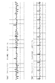
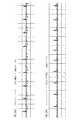
図6〜8を参照すると、電極パッチ34の原型に関する試験ECG結果が示される。試験は、Philips 3.0T Achieva(登録商標)MRIスキャナにおいて実行された。複数の高いdB/dTスキャンシーケンスが、既存の市販電極パッチ(即ち「現在の電極」)対電極パッチ34(即ち「開示された電極」)を用いて評価された。パフォーマンスを評価するために用いられる基準は、R波対T波振幅比率(比率が大きければより好適である。なぜなら、それは、MRIへの誤ったトリガリング/同期を生みだすR波としてT波が検出されることを防ぐからである)、及び基線(下に行くほど好適である。なぜなら、それは、R波検出の間R波が邪魔されることを防ぐからである)における変動(又はRMSノイズ)を含む。図6は、拡散加重撮像(DWI)スキャンに関する結果を示す。図7は、フィールドエコー、エコープラナ撮像(FE−EPI)スキャンに関する結果を示す。図8は、サーベイスキャンに関する結果を示す。
6-8, test ECG results for the
本発明が、好ましい実施形態を参照して説明されてきた。もちろん、上記の詳細な説明を読み、理解すれば、他者は修正及び変更を思いつくであろう。それらの修正及び変更が添付の特許請求の範囲又はその均等物の範囲内にある限り、本発明は、すべての斯かる修正及び変更を含むものとして構築されることが意図される。 The invention has been described with reference to the preferred embodiments. Of course, other modifications and variations will occur to others upon reading and understanding the above detailed description. It is intended that the present invention be constructed to include all such modifications and changes as long as those modifications and changes fall within the scope of the appended claims or their equivalents.
Claims (19)
プラスチック又はポリマーシートと、
前記プラスチック又はポリマーシートに配置され、1ohm/square又はこれより高いシート抵抗を持つ導電性トレースと、
前記導電性トレースに配置され、人間の皮膚に取付けられるよう構成される電極とを有する電極パッチ。 An electrode patch used for biopotential measurement in a magnetic resonance environment,
A plastic or polymer sheet;
A conductive trace disposed on the plastic or polymer sheet and having a sheet resistance of 1 ohm / square or higher;
An electrode patch having an electrode disposed on the conductive trace and configured to be attached to human skin.
プラスチック又はポリマーシートと、
前記プラスチック又はポリマーシートに配置される炭素ベースの導電性トレースと、
前記炭素ベースの導電性トレースに配置され、人間の皮膚に取付けられるよう構成される電極とを有する電極パッチ。 An electrode patch used for biopotential measurement in a magnetic resonance environment,
A plastic or polymer sheet;
Carbon-based conductive traces disposed on the plastic or polymer sheet;
An electrode patch having electrodes disposed on the carbon-based conductive trace and configured to be attached to human skin.
前記電気絶縁保護層が、前記電極をカバーしない、請求項1乃至11のいずれか一項に記載の電極パッチ。 Further comprising an electrically insulating protective layer disposed over the conductive trace and the plastic or polymer sheet;
The electrode patch according to claim 1, wherein the electrically insulating protective layer does not cover the electrode.
請求項1乃至15のいずれか一項に記載の電極パッチと、
生体電位測定を受信するよう構成されるモニタ又はレシーバユニットと、
前記モニタ又はレシーバユニットと前記電極パッチの前記電極とを電気的に接続するケーブルとを有する、生体電位測定装置。 A biopotential measuring device comprising:
The electrode patch according to any one of claims 1 to 15,
A monitor or receiver unit configured to receive a biopotential measurement;
A biopotential measurement apparatus comprising a cable for electrically connecting the monitor or receiver unit and the electrode of the electrode patch.
請求項16乃至18の任意の一項に記載の生体電位測定装置とを有するシステムであって、
前記電極パッチが、前記磁気共鳴スキャナの検査領域に配置される、システム。 A magnetic resonance scanner;
A system comprising the bioelectric potential measuring device according to any one of claims 16 to 18,
The system, wherein the electrode patch is disposed in an examination area of the magnetic resonance scanner.
Applications Claiming Priority (5)
| Application Number | Priority Date | Filing Date | Title |
|---|---|---|---|
| US201261651838P | 2012-05-25 | 2012-05-25 | |
| US61/651,838 | 2012-05-25 | ||
| US201261739751P | 2012-12-20 | 2012-12-20 | |
| US61/739,751 | 2012-12-20 | ||
| PCT/IB2013/053887 WO2013175343A1 (en) | 2012-05-25 | 2013-05-13 | Magnetic resonance safe electrode for biopotential measurements |
Publications (2)
| Publication Number | Publication Date |
|---|---|
| JP2015517373A true JP2015517373A (en) | 2015-06-22 |
| JP2015517373A5 JP2015517373A5 (en) | 2016-07-07 |
Family
ID=48771664
Family Applications (1)
| Application Number | Title | Priority Date | Filing Date |
|---|---|---|---|
| JP2015513310A Pending JP2015517373A (en) | 2012-05-25 | 2013-05-13 | Magnetic resonance safe electrode for biopotential measurement |
Country Status (6)
| Country | Link |
|---|---|
| US (1) | US20150141791A1 (en) |
| EP (1) | EP2854629A1 (en) |
| JP (1) | JP2015517373A (en) |
| CN (1) | CN104394763B (en) |
| BR (1) | BR112014029065A2 (en) |
| WO (1) | WO2013175343A1 (en) |
Families Citing this family (8)
| Publication number | Priority date | Publication date | Assignee | Title |
|---|---|---|---|---|
| CN105361865B (en) * | 2014-08-18 | 2021-06-08 | 三星电子株式会社 | Wearable biological characteristic information measuring device |
| US10918296B1 (en) * | 2015-07-13 | 2021-02-16 | Vital Connect, Inc. | Flexible electrocardiogram (ECG) pads |
| US9891301B2 (en) * | 2015-09-18 | 2018-02-13 | University Of Iowa Research Foundation | Apparatus and methods for dynamical tracking of mechanical activity within cell populations |
| US20170079543A1 (en) * | 2015-09-18 | 2017-03-23 | Neurorex Inc | Imaging compatible electrode-set for measurement of body electrical signals and methods for fabricating the same using ink-jet printing |
| AT519280B1 (en) * | 2016-10-21 | 2019-08-15 | Leonh Lang | Electrode for attachment to human skin |
| CN107811633A (en) * | 2017-10-24 | 2018-03-20 | 海南聚能科技创新研究院有限公司 | A kind of portable cardiac electrode slice |
| US20210186403A1 (en) * | 2019-12-23 | 2021-06-24 | Nikomed USA, Inc. | Printed Electrocardiogram Leads for Medical Applications |
| US11883176B2 (en) | 2020-05-29 | 2024-01-30 | The Research Foundation For The State University Of New York | Low-power wearable smart ECG patch with on-board analytics |
Citations (6)
| Publication number | Priority date | Publication date | Assignee | Title |
|---|---|---|---|---|
| JPH0523399A (en) * | 1991-07-22 | 1993-02-02 | Nippon Zeon Co Ltd | Medical appliance fitted with electrode |
| JPH09276240A (en) * | 1995-12-08 | 1997-10-28 | R Keith Ferrari | Radiolucency percutaneously stimulating electrode |
| JP2006509528A (en) * | 2001-11-02 | 2006-03-23 | ザ ヘンリー エム ジャクソン ファウンデーション | Cardiac gating method and system |
| JP2008539041A (en) * | 2005-04-28 | 2008-11-13 | アイビー バイオメディカル システムズ, インコーポレイテッド | ECG cable for use in MRI |
| JP2011528578A (en) * | 2008-07-18 | 2011-11-24 | フレクスコン カンパニー インク | High impedance signal detection system and method for use in an electrocardiograph system |
| JP2012035131A (en) * | 2005-04-15 | 2012-02-23 | Ivy Biomedical Systems Inc | Wireless transmitter |
Family Cites Families (16)
| Publication number | Priority date | Publication date | Assignee | Title |
|---|---|---|---|---|
| US2388913A (en) * | 1944-05-22 | 1945-11-13 | Standard Oil Dev Co | Separating acetylenes from light hydrocarbons |
| US5505200A (en) * | 1994-01-28 | 1996-04-09 | Minnesota Mining And Manufacturing | Biomedical conductor containing inorganic oxides and biomedical electrodes prepared therefrom |
| US5935082A (en) * | 1995-01-26 | 1999-08-10 | Cambridge Heart, Inc. | Assessing cardiac electrical stability |
| US5571165A (en) * | 1995-12-08 | 1996-11-05 | Ferrari; R. Keith | X-ray transmissive transcutaneous stimulating electrode |
| US6073039A (en) * | 1997-11-07 | 2000-06-06 | The United States Of America As Represented By The Department Of Health And Human Services | Device and method for real-time monitoring of an electrocardiogram during magnetic resonance imaging |
| US7844347B2 (en) * | 2002-12-06 | 2010-11-30 | Medtronic, Inc. | Medical devices incorporating carbon nanotube material and methods of fabricating same |
| EP1488738A1 (en) * | 2003-06-19 | 2004-12-22 | Instrumentarium Corporation | Patient cable for medical measurements |
| WO2006044868A1 (en) * | 2004-10-20 | 2006-04-27 | Nervonix, Inc. | An active electrode, bio-impedance based, tissue discrimination system and methods and use |
| DE102005004859A1 (en) * | 2005-02-02 | 2006-08-17 | Siemens Ag | ECG electrode assembly for MR applications |
| US10327701B2 (en) * | 2005-05-06 | 2019-06-25 | The General Hospital Corporation | Apparatuses and methods for electrophysiological signal delivery and recording during MRI |
| WO2009055397A2 (en) * | 2007-10-24 | 2009-04-30 | Hmicro, Inc. | Multi-electrode sensing patch for long-term physiological monitoring with swappable electronics, radio, and battery, and methods of use |
| WO2010030373A2 (en) * | 2008-09-12 | 2010-03-18 | Surgivision, Inc. | Intrabody mri stacked flat loop antennas and related systems |
| WO2010088325A2 (en) * | 2009-01-29 | 2010-08-05 | Cornell Research Foundation, Inc. | Electrocardiogram monitor |
| US20100261991A1 (en) * | 2009-04-11 | 2010-10-14 | Chen Guangren | Apparatus for wire or wireless ECG machine with only two leads |
| US8248183B2 (en) * | 2009-07-30 | 2012-08-21 | Sierra Wireless, Inc. | Circuit board pad having impedance matched to a transmission line and method for providing same |
| US9061134B2 (en) * | 2009-09-23 | 2015-06-23 | Ripple Llc | Systems and methods for flexible electrodes |
-
2013
- 2013-05-13 JP JP2015513310A patent/JP2015517373A/en active Pending
- 2013-05-13 US US14/400,065 patent/US20150141791A1/en not_active Abandoned
- 2013-05-13 CN CN201380033779.0A patent/CN104394763B/en not_active Expired - Fee Related
- 2013-05-13 EP EP13735070.8A patent/EP2854629A1/en not_active Withdrawn
- 2013-05-13 WO PCT/IB2013/053887 patent/WO2013175343A1/en active Application Filing
- 2013-05-13 BR BR112014029065A patent/BR112014029065A2/en not_active Application Discontinuation
Patent Citations (6)
| Publication number | Priority date | Publication date | Assignee | Title |
|---|---|---|---|---|
| JPH0523399A (en) * | 1991-07-22 | 1993-02-02 | Nippon Zeon Co Ltd | Medical appliance fitted with electrode |
| JPH09276240A (en) * | 1995-12-08 | 1997-10-28 | R Keith Ferrari | Radiolucency percutaneously stimulating electrode |
| JP2006509528A (en) * | 2001-11-02 | 2006-03-23 | ザ ヘンリー エム ジャクソン ファウンデーション | Cardiac gating method and system |
| JP2012035131A (en) * | 2005-04-15 | 2012-02-23 | Ivy Biomedical Systems Inc | Wireless transmitter |
| JP2008539041A (en) * | 2005-04-28 | 2008-11-13 | アイビー バイオメディカル システムズ, インコーポレイテッド | ECG cable for use in MRI |
| JP2011528578A (en) * | 2008-07-18 | 2011-11-24 | フレクスコン カンパニー インク | High impedance signal detection system and method for use in an electrocardiograph system |
Also Published As
| Publication number | Publication date |
|---|---|
| CN104394763A (en) | 2015-03-04 |
| US20150141791A1 (en) | 2015-05-21 |
| BR112014029065A2 (en) | 2017-06-27 |
| EP2854629A1 (en) | 2015-04-08 |
| CN104394763B (en) | 2019-08-27 |
| WO2013175343A1 (en) | 2013-11-28 |
Similar Documents
| Publication | Publication Date | Title |
|---|---|---|
| JP6255010B2 (en) | Magnetic resonance safe cable for biopotential measurement | |
| JP2015517373A (en) | Magnetic resonance safe electrode for biopotential measurement | |
| Krakow et al. | EEG recording during fMRI experiments: image quality | |
| EP1903935B1 (en) | Apparatuses for electrophysiological signal delivery and recording during mri | |
| US8494620B2 (en) | Electrocardiograph for magnetic resonance imaging and electrode patch for same | |
| US7294785B2 (en) | Patient cable for medical measurements | |
| AU2002363426A1 (en) | Cardiac gating method and system | |
| EP1450667A2 (en) | Cardiac gating method and system | |
| US20040225210A1 (en) | Electrode lead-set for use with bioelectric signal detection/acquisition devices | |
| JP6073921B2 (en) | ECG sensor mat | |
| US11986282B2 (en) | System and methods for detecting electromagnetic interference in patients during magnetic resonance imaging | |
| CN105813556B (en) | Planar magnetic resonance safety cable for biopotential measurements | |
| JP5666818B2 (en) | Biological monitoring device for magnetic resonance experiments | |
| EP4081111B1 (en) | Rf coil with integrated vital signs detector | |
| US10271736B2 (en) | Low cost magnetic resonance safe probe for temperature measurement | |
| GB2272567A (en) | Electric lead assembly for use in MR or other electro-magnetic environment |
Legal Events
| Date | Code | Title | Description |
|---|---|---|---|
| A521 | Request for written amendment filed |
Free format text: JAPANESE INTERMEDIATE CODE: A523 Effective date: 20160511 |
|
| A621 | Written request for application examination |
Free format text: JAPANESE INTERMEDIATE CODE: A621 Effective date: 20160511 |
|
| RD04 | Notification of resignation of power of attorney |
Free format text: JAPANESE INTERMEDIATE CODE: A7424 Effective date: 20170214 |
|
| A131 | Notification of reasons for refusal |
Free format text: JAPANESE INTERMEDIATE CODE: A131 Effective date: 20170221 |
|
| A977 | Report on retrieval |
Free format text: JAPANESE INTERMEDIATE CODE: A971007 Effective date: 20170222 |
|
| A601 | Written request for extension of time |
Free format text: JAPANESE INTERMEDIATE CODE: A601 Effective date: 20170512 |
|
| A02 | Decision of refusal |
Free format text: JAPANESE INTERMEDIATE CODE: A02 Effective date: 20180111 |
|
| A521 | Request for written amendment filed |
Free format text: JAPANESE INTERMEDIATE CODE: A523 Effective date: 20180413 |
|
| A911 | Transfer to examiner for re-examination before appeal (zenchi) |
Free format text: JAPANESE INTERMEDIATE CODE: A911 Effective date: 20180423 |
|
| A912 | Re-examination (zenchi) completed and case transferred to appeal board |
Free format text: JAPANESE INTERMEDIATE CODE: A912 Effective date: 20180518 |