JP2015509823A - Polymer microfiltration device, manufacturing method thereof and use of microfiltration device - Google Patents
Polymer microfiltration device, manufacturing method thereof and use of microfiltration device Download PDFInfo
- Publication number
- JP2015509823A JP2015509823A JP2014543582A JP2014543582A JP2015509823A JP 2015509823 A JP2015509823 A JP 2015509823A JP 2014543582 A JP2014543582 A JP 2014543582A JP 2014543582 A JP2014543582 A JP 2014543582A JP 2015509823 A JP2015509823 A JP 2015509823A
- Authority
- JP
- Japan
- Prior art keywords
- microfilter
- opening
- filter
- layer
- filter holder
- Prior art date
- Legal status (The legal status is an assumption and is not a legal conclusion. Google has not performed a legal analysis and makes no representation as to the accuracy of the status listed.)
- Pending
Links
- 229920000642 polymer Polymers 0.000 title claims abstract description 69
- 238000004519 manufacturing process Methods 0.000 title description 53
- 238000001471 micro-filtration Methods 0.000 title description 24
- 238000000034 method Methods 0.000 claims abstract description 154
- 239000004593 Epoxy Substances 0.000 claims abstract description 92
- 238000004458 analytical method Methods 0.000 claims abstract description 58
- 210000001124 body fluid Anatomy 0.000 claims abstract description 37
- 239000010410 layer Substances 0.000 claims description 189
- 239000000758 substrate Substances 0.000 claims description 96
- 239000000463 material Substances 0.000 claims description 77
- 239000007788 liquid Substances 0.000 claims description 62
- 239000000523 sample Substances 0.000 claims description 62
- 210000004369 blood Anatomy 0.000 claims description 46
- 239000008280 blood Substances 0.000 claims description 46
- 238000001914 filtration Methods 0.000 claims description 45
- 238000000576 coating method Methods 0.000 claims description 43
- 239000011248 coating agent Substances 0.000 claims description 42
- 238000009826 distribution Methods 0.000 claims description 22
- 239000011148 porous material Substances 0.000 claims description 19
- 239000012491 analyte Substances 0.000 claims description 18
- 239000007769 metal material Substances 0.000 claims description 16
- 238000012360 testing method Methods 0.000 claims description 13
- 230000003287 optical effect Effects 0.000 claims description 11
- 239000003153 chemical reaction reagent Substances 0.000 claims description 10
- 230000015572 biosynthetic process Effects 0.000 claims description 8
- 239000012530 fluid Substances 0.000 claims description 8
- 229920000647 polyepoxide Polymers 0.000 claims description 7
- 239000003822 epoxy resin Substances 0.000 claims description 6
- 230000006835 compression Effects 0.000 claims description 2
- 238000007906 compression Methods 0.000 claims description 2
- 229920002521 macromolecule Polymers 0.000 claims description 2
- 239000013047 polymeric layer Substances 0.000 claims 5
- 239000010839 body fluid Substances 0.000 abstract description 24
- 238000013461 design Methods 0.000 abstract description 4
- 238000011160 research Methods 0.000 abstract description 4
- 239000010408 film Substances 0.000 description 233
- 210000004027 cell Anatomy 0.000 description 134
- 230000008569 process Effects 0.000 description 78
- 208000005443 Circulating Neoplastic Cells Diseases 0.000 description 36
- 210000005266 circulating tumour cell Anatomy 0.000 description 24
- 229920002120 photoresistant polymer Polymers 0.000 description 21
- 239000012528 membrane Substances 0.000 description 18
- 206010028980 Neoplasm Diseases 0.000 description 16
- 229920001721 polyimide Polymers 0.000 description 16
- 210000000265 leukocyte Anatomy 0.000 description 15
- 201000011510 cancer Diseases 0.000 description 14
- 108090000623 proteins and genes Proteins 0.000 description 12
- 230000001605 fetal effect Effects 0.000 description 11
- 238000010186 staining Methods 0.000 description 11
- 239000011534 wash buffer Substances 0.000 description 11
- 210000003743 erythrocyte Anatomy 0.000 description 10
- RYGMFSIKBFXOCR-UHFFFAOYSA-N Copper Chemical compound [Cu] RYGMFSIKBFXOCR-UHFFFAOYSA-N 0.000 description 9
- 238000007901 in situ hybridization Methods 0.000 description 9
- 210000004881 tumor cell Anatomy 0.000 description 9
- 108020004414 DNA Proteins 0.000 description 8
- 239000000090 biomarker Substances 0.000 description 8
- 229910052751 metal Inorganic materials 0.000 description 8
- 239000002184 metal Substances 0.000 description 8
- 239000000126 substance Substances 0.000 description 8
- 229910052802 copper Inorganic materials 0.000 description 7
- 239000010949 copper Substances 0.000 description 7
- 239000011888 foil Substances 0.000 description 7
- 239000003550 marker Substances 0.000 description 7
- 108091023037 Aptamer Proteins 0.000 description 6
- 150000001875 compounds Chemical class 0.000 description 6
- 108020004999 messenger RNA Proteins 0.000 description 6
- 108020004707 nucleic acids Proteins 0.000 description 6
- 102000039446 nucleic acids Human genes 0.000 description 6
- 150000007523 nucleic acids Chemical class 0.000 description 6
- 239000004642 Polyimide Substances 0.000 description 5
- 210000000601 blood cell Anatomy 0.000 description 5
- 229940079593 drug Drugs 0.000 description 5
- 239000003814 drug Substances 0.000 description 5
- 238000002509 fluorescent in situ hybridization Methods 0.000 description 5
- 230000014509 gene expression Effects 0.000 description 5
- PCHJSUWPFVWCPO-UHFFFAOYSA-N gold Chemical compound [Au] PCHJSUWPFVWCPO-UHFFFAOYSA-N 0.000 description 5
- 229910052737 gold Inorganic materials 0.000 description 5
- 239000010931 gold Substances 0.000 description 5
- 239000011368 organic material Substances 0.000 description 5
- 210000005259 peripheral blood Anatomy 0.000 description 5
- 239000011886 peripheral blood Substances 0.000 description 5
- 229920003229 poly(methyl methacrylate) Polymers 0.000 description 5
- 238000012545 processing Methods 0.000 description 5
- 230000000717 retained effect Effects 0.000 description 5
- 238000000926 separation method Methods 0.000 description 5
- 238000012163 sequencing technique Methods 0.000 description 5
- 239000002699 waste material Substances 0.000 description 5
- XUIMIQQOPSSXEZ-UHFFFAOYSA-N Silicon Chemical compound [Si] XUIMIQQOPSSXEZ-UHFFFAOYSA-N 0.000 description 4
- 239000000872 buffer Substances 0.000 description 4
- 238000012512 characterization method Methods 0.000 description 4
- 238000012258 culturing Methods 0.000 description 4
- 201000010099 disease Diseases 0.000 description 4
- 208000037265 diseases, disorders, signs and symptoms Diseases 0.000 description 4
- 230000000694 effects Effects 0.000 description 4
- 210000002919 epithelial cell Anatomy 0.000 description 4
- 239000007850 fluorescent dye Substances 0.000 description 4
- 238000011223 gene expression profiling Methods 0.000 description 4
- 238000003125 immunofluorescent labeling Methods 0.000 description 4
- 238000001459 lithography Methods 0.000 description 4
- -1 polyethylene terephthalate Polymers 0.000 description 4
- 239000004926 polymethyl methacrylate Substances 0.000 description 4
- 102000004169 proteins and genes Human genes 0.000 description 4
- 229910052710 silicon Inorganic materials 0.000 description 4
- 239000010703 silicon Substances 0.000 description 4
- 230000001225 therapeutic effect Effects 0.000 description 4
- 210000001519 tissue Anatomy 0.000 description 4
- 238000005406 washing Methods 0.000 description 4
- XLYOFNOQVPJJNP-UHFFFAOYSA-N water Substances O XLYOFNOQVPJJNP-UHFFFAOYSA-N 0.000 description 4
- FWBHETKCLVMNFS-UHFFFAOYSA-N 4',6-Diamino-2-phenylindol Chemical compound C1=CC(C(=N)N)=CC=C1C1=CC2=CC=C(C(N)=N)C=C2N1 FWBHETKCLVMNFS-UHFFFAOYSA-N 0.000 description 3
- 102000004190 Enzymes Human genes 0.000 description 3
- 108090000790 Enzymes Proteins 0.000 description 3
- 101000738771 Homo sapiens Receptor-type tyrosine-protein phosphatase C Proteins 0.000 description 3
- 108700011259 MicroRNAs Proteins 0.000 description 3
- 102100034256 Mucin-1 Human genes 0.000 description 3
- 108010008707 Mucin-1 Proteins 0.000 description 3
- 102100037422 Receptor-type tyrosine-protein phosphatase C Human genes 0.000 description 3
- 108090000184 Selectins Proteins 0.000 description 3
- 102000003800 Selectins Human genes 0.000 description 3
- 210000001175 cerebrospinal fluid Anatomy 0.000 description 3
- 210000002358 circulating endothelial cell Anatomy 0.000 description 3
- 238000003745 diagnosis Methods 0.000 description 3
- 239000011521 glass Substances 0.000 description 3
- 238000010191 image analysis Methods 0.000 description 3
- 238000003384 imaging method Methods 0.000 description 3
- 239000012212 insulator Substances 0.000 description 3
- 239000002679 microRNA Substances 0.000 description 3
- 238000012986 modification Methods 0.000 description 3
- 230000004048 modification Effects 0.000 description 3
- 230000035772 mutation Effects 0.000 description 3
- 239000007787 solid Substances 0.000 description 3
- 239000000243 solution Substances 0.000 description 3
- 210000000130 stem cell Anatomy 0.000 description 3
- 238000002560 therapeutic procedure Methods 0.000 description 3
- 239000010409 thin film Substances 0.000 description 3
- YBJHBAHKTGYVGT-ZKWXMUAHSA-N (+)-Biotin Chemical compound N1C(=O)N[C@@H]2[C@H](CCCCC(=O)O)SC[C@@H]21 YBJHBAHKTGYVGT-ZKWXMUAHSA-N 0.000 description 2
- 108010017384 Blood Proteins Proteins 0.000 description 2
- 102000004506 Blood Proteins Human genes 0.000 description 2
- 108091003079 Bovine Serum Albumin Proteins 0.000 description 2
- 102100032912 CD44 antigen Human genes 0.000 description 2
- OKTJSMMVPCPJKN-UHFFFAOYSA-N Carbon Chemical compound [C] OKTJSMMVPCPJKN-UHFFFAOYSA-N 0.000 description 2
- VYZAMTAEIAYCRO-UHFFFAOYSA-N Chromium Chemical compound [Cr] VYZAMTAEIAYCRO-UHFFFAOYSA-N 0.000 description 2
- 102000018651 Epithelial Cell Adhesion Molecule Human genes 0.000 description 2
- 108010066687 Epithelial Cell Adhesion Molecule Proteins 0.000 description 2
- 239000004812 Fluorinated ethylene propylene Substances 0.000 description 2
- 206010064571 Gene mutation Diseases 0.000 description 2
- 101000868273 Homo sapiens CD44 antigen Proteins 0.000 description 2
- 101001012157 Homo sapiens Receptor tyrosine-protein kinase erbB-2 Proteins 0.000 description 2
- 206010061218 Inflammation Diseases 0.000 description 2
- VVQNEPGJFQJSBK-UHFFFAOYSA-N Methyl methacrylate Chemical compound COC(=O)C(C)=C VVQNEPGJFQJSBK-UHFFFAOYSA-N 0.000 description 2
- 241000699666 Mus <mouse, genus> Species 0.000 description 2
- PXHVJJICTQNCMI-UHFFFAOYSA-N Nickel Chemical compound [Ni] PXHVJJICTQNCMI-UHFFFAOYSA-N 0.000 description 2
- 108010035766 P-Selectin Proteins 0.000 description 2
- 102100023472 P-selectin Human genes 0.000 description 2
- 229920001774 Perfluoroether Polymers 0.000 description 2
- 102100030086 Receptor tyrosine-protein kinase erbB-2 Human genes 0.000 description 2
- 238000001015 X-ray lithography Methods 0.000 description 2
- 229910052782 aluminium Inorganic materials 0.000 description 2
- XAGFODPZIPBFFR-UHFFFAOYSA-N aluminium Chemical compound [Al] XAGFODPZIPBFFR-UHFFFAOYSA-N 0.000 description 2
- 239000000427 antigen Substances 0.000 description 2
- 108091007433 antigens Proteins 0.000 description 2
- 102000036639 antigens Human genes 0.000 description 2
- 238000003556 assay Methods 0.000 description 2
- 238000011001 backwashing Methods 0.000 description 2
- 239000011324 bead Substances 0.000 description 2
- 230000027455 binding Effects 0.000 description 2
- 230000005540 biological transmission Effects 0.000 description 2
- 230000000903 blocking effect Effects 0.000 description 2
- 210000001185 bone marrow Anatomy 0.000 description 2
- 238000004113 cell culture Methods 0.000 description 2
- 238000004140 cleaning Methods 0.000 description 2
- 239000011247 coating layer Substances 0.000 description 2
- 239000011889 copper foil Substances 0.000 description 2
- 230000002950 deficient Effects 0.000 description 2
- LOKCTEFSRHRXRJ-UHFFFAOYSA-I dipotassium trisodium dihydrogen phosphate hydrogen phosphate dichloride Chemical group P(=O)(O)(O)[O-].[K+].P(=O)(O)([O-])[O-].[Na+].[Na+].[Cl-].[K+].[Cl-].[Na+] LOKCTEFSRHRXRJ-UHFFFAOYSA-I 0.000 description 2
- 238000011143 downstream manufacturing Methods 0.000 description 2
- 210000002889 endothelial cell Anatomy 0.000 description 2
- 238000009585 enzyme analysis Methods 0.000 description 2
- 239000012091 fetal bovine serum Substances 0.000 description 2
- 238000000684 flow cytometry Methods 0.000 description 2
- 239000012634 fragment Substances 0.000 description 2
- 230000002068 genetic effect Effects 0.000 description 2
- 239000001963 growth medium Substances 0.000 description 2
- LNEPOXFFQSENCJ-UHFFFAOYSA-N haloperidol Chemical compound C1CC(O)(C=2C=CC(Cl)=CC=2)CCN1CCCC(=O)C1=CC=C(F)C=C1 LNEPOXFFQSENCJ-UHFFFAOYSA-N 0.000 description 2
- 238000003365 immunocytochemistry Methods 0.000 description 2
- 238000010166 immunofluorescence Methods 0.000 description 2
- 238000011534 incubation Methods 0.000 description 2
- 230000004054 inflammatory process Effects 0.000 description 2
- 238000002347 injection Methods 0.000 description 2
- 239000007924 injection Substances 0.000 description 2
- 239000003446 ligand Substances 0.000 description 2
- 230000007246 mechanism Effects 0.000 description 2
- 239000011859 microparticle Substances 0.000 description 2
- 239000002105 nanoparticle Substances 0.000 description 2
- 230000002018 overexpression Effects 0.000 description 2
- 239000002245 particle Substances 0.000 description 2
- 230000001717 pathogenic effect Effects 0.000 description 2
- 229920009441 perflouroethylene propylene Polymers 0.000 description 2
- 239000002953 phosphate buffered saline Substances 0.000 description 2
- 229920003223 poly(pyromellitimide-1,4-diphenyl ether) Polymers 0.000 description 2
- 229920001223 polyethylene glycol Polymers 0.000 description 2
- 229920000139 polyethylene terephthalate Polymers 0.000 description 2
- 239000005020 polyethylene terephthalate Substances 0.000 description 2
- 229920006254 polymer film Polymers 0.000 description 2
- 229920001343 polytetrafluoroethylene Polymers 0.000 description 2
- 239000004810 polytetrafluoroethylene Substances 0.000 description 2
- 108090000765 processed proteins & peptides Proteins 0.000 description 2
- 102000004196 processed proteins & peptides Human genes 0.000 description 2
- 210000002307 prostate Anatomy 0.000 description 2
- 102000005962 receptors Human genes 0.000 description 2
- 108020003175 receptors Proteins 0.000 description 2
- 238000011084 recovery Methods 0.000 description 2
- 239000012723 sample buffer Substances 0.000 description 2
- 238000004528 spin coating Methods 0.000 description 2
- 229920001059 synthetic polymer Polymers 0.000 description 2
- 230000005945 translocation Effects 0.000 description 2
- 210000003462 vein Anatomy 0.000 description 2
- 230000035899 viability Effects 0.000 description 2
- 108091032973 (ribonucleotides)n+m Proteins 0.000 description 1
- QTBSBXVTEAMEQO-UHFFFAOYSA-M Acetate Chemical compound CC([O-])=O QTBSBXVTEAMEQO-UHFFFAOYSA-M 0.000 description 1
- 108090001008 Avidin Proteins 0.000 description 1
- 229920002799 BoPET Polymers 0.000 description 1
- 206010006187 Breast cancer Diseases 0.000 description 1
- 208000026310 Breast neoplasm Diseases 0.000 description 1
- 208000024172 Cardiovascular disease Diseases 0.000 description 1
- 102000053642 Catalytic RNA Human genes 0.000 description 1
- 108090000994 Catalytic RNA Proteins 0.000 description 1
- 230000004544 DNA amplification Effects 0.000 description 1
- 108010024212 E-Selectin Proteins 0.000 description 1
- 102100023471 E-selectin Human genes 0.000 description 1
- 102100030708 GTPase KRas Human genes 0.000 description 1
- 241000282412 Homo Species 0.000 description 1
- 101000584612 Homo sapiens GTPase KRas Proteins 0.000 description 1
- 101000998011 Homo sapiens Keratin, type I cytoskeletal 19 Proteins 0.000 description 1
- 208000026350 Inborn Genetic disease Diseases 0.000 description 1
- 102100033420 Keratin, type I cytoskeletal 19 Human genes 0.000 description 1
- 102000011782 Keratins Human genes 0.000 description 1
- 108010076876 Keratins Proteins 0.000 description 1
- 108010092694 L-Selectin Proteins 0.000 description 1
- 102100033467 L-selectin Human genes 0.000 description 1
- 208000024556 Mendelian disease Diseases 0.000 description 1
- 241001465754 Metazoa Species 0.000 description 1
- 102100025311 Monocarboxylate transporter 7 Human genes 0.000 description 1
- 241000699670 Mus sp. Species 0.000 description 1
- 108010021466 Mutant Proteins Proteins 0.000 description 1
- 102000008300 Mutant Proteins Human genes 0.000 description 1
- 239000005041 Mylar™ Substances 0.000 description 1
- GRYLNZFGIOXLOG-UHFFFAOYSA-N Nitric acid Chemical compound O[N+]([O-])=O GRYLNZFGIOXLOG-UHFFFAOYSA-N 0.000 description 1
- CTQNGGLPUBDAKN-UHFFFAOYSA-N O-Xylene Chemical compound CC1=CC=CC=C1C CTQNGGLPUBDAKN-UHFFFAOYSA-N 0.000 description 1
- 108091034117 Oligonucleotide Proteins 0.000 description 1
- 238000010222 PCR analysis Methods 0.000 description 1
- 229930040373 Paraformaldehyde Natural products 0.000 description 1
- 239000002202 Polyethylene glycol Substances 0.000 description 1
- 108091006603 SLC16A6 Proteins 0.000 description 1
- 206010040047 Sepsis Diseases 0.000 description 1
- BLRPTPMANUNPDV-UHFFFAOYSA-N Silane Chemical compound [SiH4] BLRPTPMANUNPDV-UHFFFAOYSA-N 0.000 description 1
- 101710120037 Toxin CcdB Proteins 0.000 description 1
- GLNADSQYFUSGOU-GPTZEZBUSA-J Trypan blue Chemical compound [Na+].[Na+].[Na+].[Na+].C1=C(S([O-])(=O)=O)C=C2C=C(S([O-])(=O)=O)C(/N=N/C3=CC=C(C=C3C)C=3C=C(C(=CC=3)\N=N\C=3C(=CC4=CC(=CC(N)=C4C=3O)S([O-])(=O)=O)S([O-])(=O)=O)C)=C(O)C2=C1N GLNADSQYFUSGOU-GPTZEZBUSA-J 0.000 description 1
- 102000013127 Vimentin Human genes 0.000 description 1
- 108010065472 Vimentin Proteins 0.000 description 1
- 241000700605 Viruses Species 0.000 description 1
- JLCPHMBAVCMARE-UHFFFAOYSA-N [3-[[3-[[3-[[3-[[3-[[3-[[3-[[3-[[3-[[3-[[3-[[5-(2-amino-6-oxo-1H-purin-9-yl)-3-[[3-[[3-[[3-[[3-[[3-[[5-(2-amino-6-oxo-1H-purin-9-yl)-3-[[5-(2-amino-6-oxo-1H-purin-9-yl)-3-hydroxyoxolan-2-yl]methoxy-hydroxyphosphoryl]oxyoxolan-2-yl]methoxy-hydroxyphosphoryl]oxy-5-(5-methyl-2,4-dioxopyrimidin-1-yl)oxolan-2-yl]methoxy-hydroxyphosphoryl]oxy-5-(6-aminopurin-9-yl)oxolan-2-yl]methoxy-hydroxyphosphoryl]oxy-5-(6-aminopurin-9-yl)oxolan-2-yl]methoxy-hydroxyphosphoryl]oxy-5-(6-aminopurin-9-yl)oxolan-2-yl]methoxy-hydroxyphosphoryl]oxy-5-(6-aminopurin-9-yl)oxolan-2-yl]methoxy-hydroxyphosphoryl]oxyoxolan-2-yl]methoxy-hydroxyphosphoryl]oxy-5-(5-methyl-2,4-dioxopyrimidin-1-yl)oxolan-2-yl]methoxy-hydroxyphosphoryl]oxy-5-(4-amino-2-oxopyrimidin-1-yl)oxolan-2-yl]methoxy-hydroxyphosphoryl]oxy-5-(5-methyl-2,4-dioxopyrimidin-1-yl)oxolan-2-yl]methoxy-hydroxyphosphoryl]oxy-5-(5-methyl-2,4-dioxopyrimidin-1-yl)oxolan-2-yl]methoxy-hydroxyphosphoryl]oxy-5-(6-aminopurin-9-yl)oxolan-2-yl]methoxy-hydroxyphosphoryl]oxy-5-(6-aminopurin-9-yl)oxolan-2-yl]methoxy-hydroxyphosphoryl]oxy-5-(4-amino-2-oxopyrimidin-1-yl)oxolan-2-yl]methoxy-hydroxyphosphoryl]oxy-5-(4-amino-2-oxopyrimidin-1-yl)oxolan-2-yl]methoxy-hydroxyphosphoryl]oxy-5-(4-amino-2-oxopyrimidin-1-yl)oxolan-2-yl]methoxy-hydroxyphosphoryl]oxy-5-(6-aminopurin-9-yl)oxolan-2-yl]methoxy-hydroxyphosphoryl]oxy-5-(4-amino-2-oxopyrimidin-1-yl)oxolan-2-yl]methyl [5-(6-aminopurin-9-yl)-2-(hydroxymethyl)oxolan-3-yl] hydrogen phosphate Polymers Cc1cn(C2CC(OP(O)(=O)OCC3OC(CC3OP(O)(=O)OCC3OC(CC3O)n3cnc4c3nc(N)[nH]c4=O)n3cnc4c3nc(N)[nH]c4=O)C(COP(O)(=O)OC3CC(OC3COP(O)(=O)OC3CC(OC3COP(O)(=O)OC3CC(OC3COP(O)(=O)OC3CC(OC3COP(O)(=O)OC3CC(OC3COP(O)(=O)OC3CC(OC3COP(O)(=O)OC3CC(OC3COP(O)(=O)OC3CC(OC3COP(O)(=O)OC3CC(OC3COP(O)(=O)OC3CC(OC3COP(O)(=O)OC3CC(OC3COP(O)(=O)OC3CC(OC3COP(O)(=O)OC3CC(OC3COP(O)(=O)OC3CC(OC3COP(O)(=O)OC3CC(OC3COP(O)(=O)OC3CC(OC3COP(O)(=O)OC3CC(OC3CO)n3cnc4c(N)ncnc34)n3ccc(N)nc3=O)n3cnc4c(N)ncnc34)n3ccc(N)nc3=O)n3ccc(N)nc3=O)n3ccc(N)nc3=O)n3cnc4c(N)ncnc34)n3cnc4c(N)ncnc34)n3cc(C)c(=O)[nH]c3=O)n3cc(C)c(=O)[nH]c3=O)n3ccc(N)nc3=O)n3cc(C)c(=O)[nH]c3=O)n3cnc4c3nc(N)[nH]c4=O)n3cnc4c(N)ncnc34)n3cnc4c(N)ncnc34)n3cnc4c(N)ncnc34)n3cnc4c(N)ncnc34)O2)c(=O)[nH]c1=O JLCPHMBAVCMARE-UHFFFAOYSA-N 0.000 description 1
- 229920006397 acrylic thermoplastic Polymers 0.000 description 1
- 239000000853 adhesive Substances 0.000 description 1
- 230000001070 adhesive effect Effects 0.000 description 1
- 150000001299 aldehydes Chemical class 0.000 description 1
- HPTYUNKZVDYXLP-UHFFFAOYSA-N aluminum;trihydroxy(trihydroxysilyloxy)silane;hydrate Chemical compound O.[Al].[Al].O[Si](O)(O)O[Si](O)(O)O HPTYUNKZVDYXLP-UHFFFAOYSA-N 0.000 description 1
- 150000001412 amines Chemical class 0.000 description 1
- 230000003321 amplification Effects 0.000 description 1
- 239000003242 anti bacterial agent Substances 0.000 description 1
- 229940088710 antibiotic agent Drugs 0.000 description 1
- 239000007864 aqueous solution Substances 0.000 description 1
- 238000003491 array Methods 0.000 description 1
- 230000004888 barrier function Effects 0.000 description 1
- 235000013405 beer Nutrition 0.000 description 1
- 230000009286 beneficial effect Effects 0.000 description 1
- 102000023732 binding proteins Human genes 0.000 description 1
- 108091008324 binding proteins Proteins 0.000 description 1
- 239000012472 biological sample Substances 0.000 description 1
- 229960002685 biotin Drugs 0.000 description 1
- 235000020958 biotin Nutrition 0.000 description 1
- 239000011616 biotin Substances 0.000 description 1
- 239000004841 bisphenol A epoxy resin Substances 0.000 description 1
- 210000000988 bone and bone Anatomy 0.000 description 1
- 210000004556 brain Anatomy 0.000 description 1
- 210000000481 breast Anatomy 0.000 description 1
- 239000007853 buffer solution Substances 0.000 description 1
- 150000001720 carbohydrates Chemical class 0.000 description 1
- 235000014633 carbohydrates Nutrition 0.000 description 1
- 239000002041 carbon nanotube Substances 0.000 description 1
- 229910021393 carbon nanotube Inorganic materials 0.000 description 1
- 125000003178 carboxy group Chemical group [H]OC(*)=O 0.000 description 1
- 231100000504 carcinogenesis Toxicity 0.000 description 1
- 239000002771 cell marker Substances 0.000 description 1
- 230000008859 change Effects 0.000 description 1
- 238000006243 chemical reaction Methods 0.000 description 1
- 239000003795 chemical substances by application Substances 0.000 description 1
- 230000035605 chemotaxis Effects 0.000 description 1
- 229910052804 chromium Inorganic materials 0.000 description 1
- 239000011651 chromium Substances 0.000 description 1
- 210000001072 colon Anatomy 0.000 description 1
- 239000002299 complementary DNA Substances 0.000 description 1
- 238000010276 construction Methods 0.000 description 1
- 239000000356 contaminant Substances 0.000 description 1
- 238000001816 cooling Methods 0.000 description 1
- 101150082482 ctc gene Proteins 0.000 description 1
- 230000006378 damage Effects 0.000 description 1
- 239000000412 dendrimer Substances 0.000 description 1
- 229920000736 dendritic polymer Polymers 0.000 description 1
- 238000001514 detection method Methods 0.000 description 1
- 238000011161 development Methods 0.000 description 1
- 206010012601 diabetes mellitus Diseases 0.000 description 1
- 238000010586 diagram Methods 0.000 description 1
- 238000000502 dialysis Methods 0.000 description 1
- 230000002255 enzymatic effect Effects 0.000 description 1
- 102000052116 epidermal growth factor receptor activity proteins Human genes 0.000 description 1
- 108700015053 epidermal growth factor receptor activity proteins Proteins 0.000 description 1
- 125000003700 epoxy group Chemical group 0.000 description 1
- 238000005530 etching Methods 0.000 description 1
- HQQADJVZYDDRJT-UHFFFAOYSA-N ethene;prop-1-ene Chemical group C=C.CC=C HQQADJVZYDDRJT-UHFFFAOYSA-N 0.000 description 1
- 230000007717 exclusion Effects 0.000 description 1
- 230000001747 exhibiting effect Effects 0.000 description 1
- 238000002474 experimental method Methods 0.000 description 1
- 210000004700 fetal blood Anatomy 0.000 description 1
- 238000000799 fluorescence microscopy Methods 0.000 description 1
- 239000006260 foam Substances 0.000 description 1
- UNKQPEQSAGXBEV-UHFFFAOYSA-N formaldehyde;4-[2-(4-hydroxyphenyl)propan-2-yl]phenol Chemical compound O=C.C=1C=C(O)C=CC=1C(C)(C)C1=CC=C(O)C=C1 UNKQPEQSAGXBEV-UHFFFAOYSA-N 0.000 description 1
- 150000002270 gangliosides Chemical class 0.000 description 1
- 238000012252 genetic analysis Methods 0.000 description 1
- 239000010439 graphite Substances 0.000 description 1
- 229910002804 graphite Inorganic materials 0.000 description 1
- 229910052621 halloysite Inorganic materials 0.000 description 1
- 238000003306 harvesting Methods 0.000 description 1
- 238000007490 hematoxylin and eosin (H&E) staining Methods 0.000 description 1
- 230000005660 hydrophilic surface Effects 0.000 description 1
- 230000002209 hydrophobic effect Effects 0.000 description 1
- 125000002887 hydroxy group Chemical group [H]O* 0.000 description 1
- 238000007654 immersion Methods 0.000 description 1
- 230000036039 immunity Effects 0.000 description 1
- 238000003364 immunohistochemistry Methods 0.000 description 1
- 238000012744 immunostaining Methods 0.000 description 1
- 230000015788 innate immune response Effects 0.000 description 1
- 238000009434 installation Methods 0.000 description 1
- FBAFATDZDUQKNH-UHFFFAOYSA-M iron chloride Chemical compound [Cl-].[Fe] FBAFATDZDUQKNH-UHFFFAOYSA-M 0.000 description 1
- 210000003734 kidney Anatomy 0.000 description 1
- 238000010030 laminating Methods 0.000 description 1
- 238000011031 large-scale manufacturing process Methods 0.000 description 1
- 239000004816 latex Substances 0.000 description 1
- 229920000126 latex Polymers 0.000 description 1
- 150000002632 lipids Chemical class 0.000 description 1
- 210000004185 liver Anatomy 0.000 description 1
- 210000004072 lung Anatomy 0.000 description 1
- 239000012139 lysis buffer Substances 0.000 description 1
- 230000008774 maternal effect Effects 0.000 description 1
- 238000002844 melting Methods 0.000 description 1
- 230000008018 melting Effects 0.000 description 1
- 208000037819 metastatic cancer Diseases 0.000 description 1
- 208000011575 metastatic malignant neoplasm Diseases 0.000 description 1
- YOHYSYJDKVYCJI-UHFFFAOYSA-N n-[3-[[6-[3-(trifluoromethyl)anilino]pyrimidin-4-yl]amino]phenyl]cyclopropanecarboxamide Chemical compound FC(F)(F)C1=CC=CC(NC=2N=CN=C(NC=3C=C(NC(=O)C4CC4)C=CC=3)C=2)=C1 YOHYSYJDKVYCJI-UHFFFAOYSA-N 0.000 description 1
- 239000002071 nanotube Substances 0.000 description 1
- 229910052759 nickel Inorganic materials 0.000 description 1
- 229910017604 nitric acid Inorganic materials 0.000 description 1
- 210000004967 non-hematopoietic stem cell Anatomy 0.000 description 1
- 230000009871 nonspecific binding Effects 0.000 description 1
- 229920003986 novolac Polymers 0.000 description 1
- 238000003199 nucleic acid amplification method Methods 0.000 description 1
- 229920002866 paraformaldehyde Polymers 0.000 description 1
- 244000052769 pathogen Species 0.000 description 1
- 238000001020 plasma etching Methods 0.000 description 1
- 238000009832 plasma treatment Methods 0.000 description 1
- 229920000052 poly(p-xylylene) Polymers 0.000 description 1
- 229920000728 polyester Polymers 0.000 description 1
- 238000006116 polymerization reaction Methods 0.000 description 1
- 108091033319 polynucleotide Proteins 0.000 description 1
- 102000040430 polynucleotide Human genes 0.000 description 1
- 239000002157 polynucleotide Substances 0.000 description 1
- 229920001184 polypeptide Polymers 0.000 description 1
- 230000035935 pregnancy Effects 0.000 description 1
- 238000003793 prenatal diagnosis Methods 0.000 description 1
- 238000002360 preparation method Methods 0.000 description 1
- 238000003825 pressing Methods 0.000 description 1
- 230000001105 regulatory effect Effects 0.000 description 1
- 230000010076 replication Effects 0.000 description 1
- 230000004044 response Effects 0.000 description 1
- 108091092562 ribozyme Proteins 0.000 description 1
- 238000012216 screening Methods 0.000 description 1
- 239000002094 self assembled monolayer Substances 0.000 description 1
- 239000013545 self-assembled monolayer Substances 0.000 description 1
- 208000007056 sickle cell anemia Diseases 0.000 description 1
- 229910000077 silane Inorganic materials 0.000 description 1
- 230000000087 stabilizing effect Effects 0.000 description 1
- 238000007447 staining method Methods 0.000 description 1
- 210000002536 stromal cell Anatomy 0.000 description 1
- 238000006557 surface reaction Methods 0.000 description 1
- 208000024891 symptom Diseases 0.000 description 1
- ISXSCDLOGDJUNJ-UHFFFAOYSA-N tert-butyl prop-2-enoate Chemical compound CC(C)(C)OC(=O)C=C ISXSCDLOGDJUNJ-UHFFFAOYSA-N 0.000 description 1
- 239000003053 toxin Substances 0.000 description 1
- 231100000765 toxin Toxicity 0.000 description 1
- 108700012359 toxins Proteins 0.000 description 1
- 210000002993 trophoblast Anatomy 0.000 description 1
- 230000000381 tumorigenic effect Effects 0.000 description 1
- 241001515965 unidentified phage Species 0.000 description 1
- 210000002700 urine Anatomy 0.000 description 1
- 229960005486 vaccine Drugs 0.000 description 1
- 238000007740 vapor deposition Methods 0.000 description 1
- 210000005048 vimentin Anatomy 0.000 description 1
- 230000000007 visual effect Effects 0.000 description 1
- 238000012800 visualization Methods 0.000 description 1
- 239000008096 xylene Substances 0.000 description 1
Images


Classifications
-
- G—PHYSICS
- G01—MEASURING; TESTING
- G01N—INVESTIGATING OR ANALYSING MATERIALS BY DETERMINING THEIR CHEMICAL OR PHYSICAL PROPERTIES
- G01N33/00—Investigating or analysing materials by specific methods not covered by groups G01N1/00 - G01N31/00
- G01N33/48—Biological material, e.g. blood, urine; Haemocytometers
- G01N33/50—Chemical analysis of biological material, e.g. blood, urine; Testing involving biospecific ligand binding methods; Immunological testing
- G01N33/5005—Chemical analysis of biological material, e.g. blood, urine; Testing involving biospecific ligand binding methods; Immunological testing involving human or animal cells
-
- A—HUMAN NECESSITIES
- A61—MEDICAL OR VETERINARY SCIENCE; HYGIENE
- A61P—SPECIFIC THERAPEUTIC ACTIVITY OF CHEMICAL COMPOUNDS OR MEDICINAL PREPARATIONS
- A61P35/00—Antineoplastic agents
- A61P35/04—Antineoplastic agents specific for metastasis
-
- A—HUMAN NECESSITIES
- A61—MEDICAL OR VETERINARY SCIENCE; HYGIENE
- A61P—SPECIFIC THERAPEUTIC ACTIVITY OF CHEMICAL COMPOUNDS OR MEDICINAL PREPARATIONS
- A61P7/00—Drugs for disorders of the blood or the extracellular fluid
- A61P7/08—Plasma substitutes; Perfusion solutions; Dialytics or haemodialytics; Drugs for electrolytic or acid-base disorders, e.g. hypovolemic shock
-
- B—PERFORMING OPERATIONS; TRANSPORTING
- B01—PHYSICAL OR CHEMICAL PROCESSES OR APPARATUS IN GENERAL
- B01D—SEPARATION
- B01D29/00—Filters with filtering elements stationary during filtration, e.g. pressure or suction filters, not covered by groups B01D24/00 - B01D27/00; Filtering elements therefor
-
- B—PERFORMING OPERATIONS; TRANSPORTING
- B01—PHYSICAL OR CHEMICAL PROCESSES OR APPARATUS IN GENERAL
- B01D—SEPARATION
- B01D39/00—Filtering material for liquid or gaseous fluids
- B01D39/14—Other self-supporting filtering material ; Other filtering material
- B01D39/16—Other self-supporting filtering material ; Other filtering material of organic material, e.g. synthetic fibres
- B01D39/1692—Other shaped material, e.g. perforated or porous sheets
-
- B—PERFORMING OPERATIONS; TRANSPORTING
- B01—PHYSICAL OR CHEMICAL PROCESSES OR APPARATUS IN GENERAL
- B01D—SEPARATION
- B01D61/00—Processes of separation using semi-permeable membranes, e.g. dialysis, osmosis or ultrafiltration; Apparatus, accessories or auxiliary operations specially adapted therefor
- B01D61/14—Ultrafiltration; Microfiltration
- B01D61/18—Apparatus therefor
-
- B—PERFORMING OPERATIONS; TRANSPORTING
- B01—PHYSICAL OR CHEMICAL PROCESSES OR APPARATUS IN GENERAL
- B01D—SEPARATION
- B01D63/00—Apparatus in general for separation processes using semi-permeable membranes
- B01D63/08—Flat membrane modules
- B01D63/088—Microfluidic devices comprising semi-permeable flat membranes
-
- B—PERFORMING OPERATIONS; TRANSPORTING
- B01—PHYSICAL OR CHEMICAL PROCESSES OR APPARATUS IN GENERAL
- B01L—CHEMICAL OR PHYSICAL LABORATORY APPARATUS FOR GENERAL USE
- B01L3/00—Containers or dishes for laboratory use, e.g. laboratory glassware; Droppers
- B01L3/50—Containers for the purpose of retaining a material to be analysed, e.g. test tubes
-
- B—PERFORMING OPERATIONS; TRANSPORTING
- B01—PHYSICAL OR CHEMICAL PROCESSES OR APPARATUS IN GENERAL
- B01L—CHEMICAL OR PHYSICAL LABORATORY APPARATUS FOR GENERAL USE
- B01L3/00—Containers or dishes for laboratory use, e.g. laboratory glassware; Droppers
- B01L3/56—Labware specially adapted for transferring fluids
- B01L3/563—Joints or fittings ; Separable fluid transfer means to transfer fluids between at least two containers, e.g. connectors
- B01L3/5635—Joints or fittings ; Separable fluid transfer means to transfer fluids between at least two containers, e.g. connectors connecting two containers face to face, e.g. comprising a filter
-
- G—PHYSICS
- G01—MEASURING; TESTING
- G01N—INVESTIGATING OR ANALYSING MATERIALS BY DETERMINING THEIR CHEMICAL OR PHYSICAL PROPERTIES
- G01N1/00—Sampling; Preparing specimens for investigation
- G01N1/28—Preparing specimens for investigation including physical details of (bio-)chemical methods covered elsewhere, e.g. G01N33/50, C12Q
- G01N1/40—Concentrating samples
- G01N1/4005—Concentrating samples by transferring a selected component through a membrane
-
- G—PHYSICS
- G01—MEASURING; TESTING
- G01N—INVESTIGATING OR ANALYSING MATERIALS BY DETERMINING THEIR CHEMICAL OR PHYSICAL PROPERTIES
- G01N1/00—Sampling; Preparing specimens for investigation
- G01N1/28—Preparing specimens for investigation including physical details of (bio-)chemical methods covered elsewhere, e.g. G01N33/50, C12Q
- G01N1/40—Concentrating samples
- G01N1/4077—Concentrating samples by other techniques involving separation of suspended solids
-
- B—PERFORMING OPERATIONS; TRANSPORTING
- B01—PHYSICAL OR CHEMICAL PROCESSES OR APPARATUS IN GENERAL
- B01L—CHEMICAL OR PHYSICAL LABORATORY APPARATUS FOR GENERAL USE
- B01L2300/00—Additional constructional details
- B01L2300/06—Auxiliary integrated devices, integrated components
- B01L2300/0681—Filter
-
- B—PERFORMING OPERATIONS; TRANSPORTING
- B01—PHYSICAL OR CHEMICAL PROCESSES OR APPARATUS IN GENERAL
- B01L—CHEMICAL OR PHYSICAL LABORATORY APPARATUS FOR GENERAL USE
- B01L3/00—Containers or dishes for laboratory use, e.g. laboratory glassware; Droppers
- B01L3/50—Containers for the purpose of retaining a material to be analysed, e.g. test tubes
- B01L3/502—Containers for the purpose of retaining a material to be analysed, e.g. test tubes with fluid transport, e.g. in multi-compartment structures
-
- G—PHYSICS
- G01—MEASURING; TESTING
- G01N—INVESTIGATING OR ANALYSING MATERIALS BY DETERMINING THEIR CHEMICAL OR PHYSICAL PROPERTIES
- G01N1/00—Sampling; Preparing specimens for investigation
- G01N1/28—Preparing specimens for investigation including physical details of (bio-)chemical methods covered elsewhere, e.g. G01N33/50, C12Q
- G01N1/40—Concentrating samples
- G01N1/4077—Concentrating samples by other techniques involving separation of suspended solids
- G01N2001/4088—Concentrating samples by other techniques involving separation of suspended solids filtration
-
- Y—GENERAL TAGGING OF NEW TECHNOLOGICAL DEVELOPMENTS; GENERAL TAGGING OF CROSS-SECTIONAL TECHNOLOGIES SPANNING OVER SEVERAL SECTIONS OF THE IPC; TECHNICAL SUBJECTS COVERED BY FORMER USPC CROSS-REFERENCE ART COLLECTIONS [XRACs] AND DIGESTS
- Y10—TECHNICAL SUBJECTS COVERED BY FORMER USPC
- Y10T—TECHNICAL SUBJECTS COVERED BY FORMER US CLASSIFICATION
- Y10T29/00—Metal working
- Y10T29/49—Method of mechanical manufacture
- Y10T29/49826—Assembling or joining
- Y10T29/49947—Assembling or joining by applying separate fastener
- Y10T29/49963—Threaded fastener
Landscapes
- Chemical & Material Sciences (AREA)
- Health & Medical Sciences (AREA)
- Chemical Kinetics & Catalysis (AREA)
- Life Sciences & Earth Sciences (AREA)
- Engineering & Computer Science (AREA)
- General Health & Medical Sciences (AREA)
- Immunology (AREA)
- Analytical Chemistry (AREA)
- Hematology (AREA)
- Pathology (AREA)
- General Physics & Mathematics (AREA)
- Biochemistry (AREA)
- Physics & Mathematics (AREA)
- Water Supply & Treatment (AREA)
- Clinical Laboratory Science (AREA)
- Medicinal Chemistry (AREA)
- Urology & Nephrology (AREA)
- Biomedical Technology (AREA)
- Molecular Biology (AREA)
- Public Health (AREA)
- Animal Behavior & Ethology (AREA)
- Pharmacology & Pharmacy (AREA)
- Organic Chemistry (AREA)
- Nuclear Medicine, Radiotherapy & Molecular Imaging (AREA)
- General Chemical & Material Sciences (AREA)
- Veterinary Medicine (AREA)
- Biotechnology (AREA)
- Cell Biology (AREA)
- Microbiology (AREA)
- Food Science & Technology (AREA)
- Tropical Medicine & Parasitology (AREA)
- Dispersion Chemistry (AREA)
- Oncology (AREA)
- Diabetes (AREA)
- Bioinformatics & Cheminformatics (AREA)
- Apparatus Associated With Microorganisms And Enzymes (AREA)
- Infusion, Injection, And Reservoir Apparatuses (AREA)
- Sampling And Sample Adjustment (AREA)
- Separation Using Semi-Permeable Membranes (AREA)
- Polyesters Or Polycarbonates (AREA)
Abstract
マイクロフィルタは、エポキシ系の光画定可能な乾燥膜から形成された高分子層と、高分子層を介してそれぞれ延在する複数のアパーチャと、を含む。ユニークなフィルタホルダの設計および希少細胞を収集し、フィルタホルダ内分析を実施可能にするためにマイクロフィルタを保持するのに適切な構成と方法が提供される。本発明はまた、体液から希少細胞を採取し、分析を実施するためのマイクロフィルタおよびフィルタホルダの使用を記載している。本発明の実施形態によるマイクロフィルタ上に収集された希少細胞は、医学および生物学研究用途に使用することができる。The microfilter includes a polymer layer formed from an epoxy-based photodefinable dry film, and a plurality of apertures each extending through the polymer layer. Appropriate configurations and methods are provided to hold the microfilter to allow unique filter holder designs and rare cells to be collected and analyzed in the filter holder. The present invention also describes the use of microfilters and filter holders to collect rare cells from body fluids and perform analysis. Rare cells collected on microfilters according to embodiments of the invention can be used for medical and biological research applications.
Description
本発明は、一般に、高分子マイクロフィルタを含む精密濾過装置、その製造方法、精密濾過装置の使用方法、及びその装置のアプリケーションに関する。 The present invention generally relates to a microfiltration device including a polymer microfilter, a method for manufacturing the same, a method for using the microfiltration device, and an application of the device.
いくつかの病状は、体液中の細胞の特定の種類の存在を検出することによって診断することができる。特に、特定の病状の特徴または示す細胞は、ある種の体液に見出される他の細胞よりも大きく、および/またはより柔軟性が低いかもしれない。したがって、体液のような液体サンプルから大きく、および/またはより柔軟性が低い細胞を収集することにより、収集された細胞に基づいて、病状を診断することも可能である。 Some medical conditions can be diagnosed by detecting the presence of certain types of cells in body fluids. In particular, a particular disease state characteristic or exhibiting cell may be larger and / or less flexible than other cells found in certain body fluids. Thus, it is also possible to diagnose a disease state based on the collected cells by collecting large and / or less flexible cells from a fluid sample such as a body fluid.
体液中に存在する他の細胞よりも大きく、及び/または柔軟性の低い細胞は、体液を濾過することによって収集することができる。例えば、状態を示す標的細胞は、標的細胞が通過するには小さすぎるが他の細胞が通過するのに十分なサイズの開口部を有するフィルタを介して体液を通すことによって収集することができる。収集されると、標的細胞の任意の数の分析を実行することができる。このような分析は、例えば、識別し、計数し、特性評価し、および/または収集された細胞を培養することを含むことができる。 Cells that are larger and / or less flexible than other cells present in the body fluid can be collected by filtering the body fluid. For example, target cells that indicate a condition can be collected by passing bodily fluid through a filter that has openings that are too small for the target cells to pass but are large enough for other cells to pass. Once collected, any number of analyzes of target cells can be performed. Such analysis can include, for example, identifying, counting, characterizing, and / or culturing the collected cells.
マイクロフィルタは、正確な孔の寸法を有し、使用中に破損せず、蛍光顕微鏡イメージングのために自動蛍光できないことが望ましい。従来、マイクロフィルタは、マイクロフィルタ上のサイズに基づいて細胞を回収するために、精密濾過装置と処理される液体サンプルにインストールされる。 Desirably, the microfilter has the correct pore size, does not break during use, and cannot be autofluorescent for fluorescence microscopy imaging. Traditionally, microfilters are installed on microfilters and processed liquid samples to collect cells based on the size on the microfilter.
<関連出願の相互参照>
本出願は、2011年4月1日に出願された特許出願PCT/US第11/30996号「高分子マイクロフィルタとその製造方法」の一部継続出願である。
<Cross-reference of related applications>
This application is a continuation-in-part of patent application PCT / US11 / 30996 “Polymer microfilter and manufacturing method thereof” filed on April 1, 2011.
本出願はまた、2011年11月21日に出願された米国仮特許出願第61/562404号「高分子精密濾過装置、その製造方法及び精密濾過装置の使用」の優先権を主張し、同出願の内容全体は、本明細書に参照によりここに取り入れられる。 This application also claims priority from US Provisional Patent Application No. 61 / 562,404, “Polymer Microfiltration Device, Method for Producing the Same, and Use of Microfiltration Device” filed on November 21, 2011. Is incorporated herein by reference in its entirety.
本出願はまた、2012年3月30日に出願された米国仮特許出願第61/618,641号「高分子精密濾過装置、その製造方法及び精密濾過装置の使用」の優先権を主張し、同出願の内容全体は、本明細書に参照によりここに取り入れられる。 This application also claims the priority of US Provisional Patent Application No. 61 / 618,641, “Polymer Microfiltration Device, Method for Producing the Same, and Use of the Microfiltration Device,” filed on March 30, 2012, The entire contents of that application are incorporated herein by reference.
本出願はまた、2012年6月1日に出願された米国仮特許出願第61/654,636号「高分子精密濾過装置、その製造方法及び精密濾過装置の使用」の優先権を主張し、同出願の内容全体は、本明細書に参照によりここに取り入れられる。 This application also claims the priority of US Provisional Patent Application No. 61 / 654,636, “Polymer Microfiltration Device, Method for Producing the Same, and Use of the Microfiltration Device,” filed on June 1, 2012, The entire contents of that application are incorporated herein by reference.
本発明の第1の面は、マイクロフィルタが開示される。実施態様によれば、マイクロフィルタは、エポキシ系の光画定可能な材料から形成された高分子層と、高分子層を介してそれぞれ延在する複数のアパーチャと、を含む。 According to a first aspect of the present invention, a microfilter is disclosed. According to an embodiment, the microfilter includes a polymer layer formed from an epoxy-based photodefinable material and a plurality of apertures each extending through the polymer layer.
本発明の別の面は、多層マイクロフィルタが開示される。実施態様によれば、マイクロフィルタは、エポキシ系の光画定可能な材料から形成され、貫通して延在する第1のアパーチャを有する第1の高分子層と、エポキシ系の光画定可能な材料から形成され貫通して延在する第2のアパーチャを有する第2の高分子層と、を備え、第1および第2のアパーチャは、第1および第2の層を貫通して延在する非線形通路を少なくとも部分的に規定する。 Another aspect of the invention discloses a multilayer microfilter. According to an embodiment, the microfilter is formed from an epoxy-based photodefinable material and has a first polymer layer having a first aperture extending therethrough and an epoxy-based photodefinable material. And a second polymer layer having a second aperture extending therethrough, the first and second apertures extending non-linearly through the first and second layers The passage is at least partially defined.
本発明のさらに別の面は、マイクロフィルタ形成方法が開示される。実施態様によれば、方法は、基板上に配された光画定可能な材料の第1の層を準備するステップと、乾燥膜の第1の層で、マスクによって規定されたパターンを形成するため、マスクを通るエネルギーに第1の層を露光するステップと、露光された乾燥膜の第1の層から、当該層を貫通して延在する複数のアパーチャを有する高分子層を形成するステップであって、複数のアパーチャの分布はパターンにより規定される、ステップと、基板から高分子層を除去するステップと、を含む。 In yet another aspect of the present invention, a method for forming a microfilter is disclosed. According to an embodiment, the method comprises the steps of providing a first layer of photodefinable material disposed on a substrate and forming a pattern defined by a mask with the first layer of dry film. Exposing the first layer to energy through the mask and forming a polymer layer having a plurality of apertures extending through the layer from the exposed first layer of the dried film. The distribution of the plurality of apertures includes a step defined by a pattern and a step of removing the polymer layer from the substrate.
本発明のさらに別の面は、多層マイクロフィルタ形成方法が開示される。実施態様によれば、方法は、基板上に配されたエポキシ系の光画定可能な乾燥膜の第1の層から、複数の第1のアパーチャを含む第1の高分子層を形成するステップと、第1の高分子層上にエポキシ系の光画定可能な乾燥膜の第2の層を被せるステップと、乾燥膜の第2の層から、複数の第2のアパーチャを含む第2の高分子層を形成するステップと、を含む。 In yet another aspect of the invention, a method for forming a multilayer microfilter is disclosed. According to an embodiment, the method includes forming a first polymer layer including a plurality of first apertures from a first layer of an epoxy-based photodefinable dry film disposed on a substrate; Applying a second layer of an epoxy-based photodefinable dry film on the first polymer layer, and a second polymer comprising a plurality of second apertures from the second layer of the dry film Forming a layer.
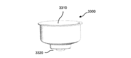
本発明のさらに別の面は、マイクロフィルタを保持するためのフィルタホルダが開示される。実施態様によれば、フィルタホルダは、フィルタを平らに保ち、所定の位置に固定し、簡単に様々な分析ステップが実施されるように設計される。 Yet another aspect of the invention discloses a filter holder for holding a microfilter. According to an embodiment, the filter holder is designed to keep the filter flat and fixed in place, so that various analysis steps can be easily performed.
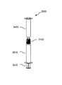
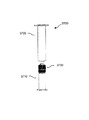
本発明のさらに別の面は、マイクロフィルタの使用方法が開示される。実施態様によれば、方法は、エポキシ系の光画定可能な乾燥膜から形成されたマイクロフィルタの複数のアパーチャを介して液体を通すステップを有し、マイクロフィルタは液体を濾過するのに十分な強度と柔軟性を有し、アパーチャは第1のタイプの体液細胞の通し、第2のタイプの体液細胞は通さないサイズで構成される。実施態様は、手動、シリンジポンプを用いて半手動、または自動で実行することができる注射器に接続する、フィルタホルダまたは真空を用いた負圧の適用を含む。 In yet another aspect of the invention, a method of using a microfilter is disclosed. According to an embodiment, the method comprises the step of passing a liquid through a plurality of apertures of a microfilter formed from an epoxy-based photodefinable dry film, the microfilter being sufficient to filter the liquid. It has strength and flexibility, and the aperture has a size that allows the passage of the first type of body fluid cells and does not pass the second type of body fluid cells. Embodiments include the application of negative pressure using a filter holder or vacuum that connects to a syringe that can be performed manually, semi-manually using a syringe pump, or automatically.
本発明のさらに別の面は、フィルタは、体液から対象の細胞を捕獲するための分析物認識要素でコーティングされている。 In yet another aspect of the invention, the filter is coated with an analyte recognition element for capturing cells of interest from bodily fluids.
本発明のさらに別の面は、液体サンプルを収集し、フィルタホルダの内部のマイクロフィルタを使用して濾過された液体サンプルを移送する、方法が開示される。 Yet another aspect of the invention discloses a method for collecting a liquid sample and transferring the filtered liquid sample using a microfilter inside the filter holder.
本発明のさらに別の面は、分析を実行するためにマイクロフィルタを使用する方法が開示される。実施態様は、細胞を分離する方法と、フィルタホルダを使用して逆洗することによりマイクロフィルタから細胞を回収する方法と、フィルタホルダ内の分析を実行する方法を提供する。 Yet another aspect of the invention discloses a method of using a microfilter to perform an analysis. Embodiments provide a method for separating cells, a method for recovering cells from a microfilter by backwashing using a filter holder, and a method for performing an analysis in the filter holder.
本発明のさらに別の面は、医療用途の分析が開示される。 Yet another aspect of the invention discloses an analysis of medical applications.
本発明および付随する多くの利点のより完全な理解は、添付の図面に関連して考慮される場合に、以下の詳細な説明を参照することによって、より良く理解されるようになることを容易に得られるであろう。 A more complete understanding of the present invention and many of the attendant advantages will become better understood by reference to the following detailed description when considered in conjunction with the accompanying drawings. Would be obtained.
今回の図面を参照すると、そこでは同様の参照番号がいくつかの図を通して同一または相当する部分を指定するように、本発明の実施の形態が模式的に詳細に開示される。 Referring now to the drawings, embodiments of the invention are schematically disclosed in detail, wherein like reference numerals designate identical or corresponding parts throughout the several views.
詳細な構成および要素などの説明で定義された事項は、本発明の包括的な理解を助けるために設けたものに過ぎない。従って、当業者は、種々の変更及び本明細書に記載の実施形態の変形が本発明の範囲および趣旨から逸脱することなくされ得ることを認識するであろう。また、周知の機能または構造は、明瞭性と簡潔性のために省略されている。本発明のいくつかの例示的な実施形態は、商業的用途の文脈で以下に記載される。このような例示的な実装形態は、添付の特許請求の範囲で定義される本発明の範囲を限定するものではない。 Matters defined in the description of detailed configurations and elements are merely provided to assist in a comprehensive understanding of the present invention. Accordingly, those skilled in the art will recognize that various modifications and variations of the embodiments described herein can be made without departing from the scope and spirit of the invention. In other instances, well-known functions or constructions have been omitted for clarity and brevity. Some exemplary embodiments of the invention are described below in the context of commercial applications. Such exemplary implementations are not intended to limit the scope of the invention as defined in the appended claims.
本発明の態様は、一般に、エポキシ系の光画定可能な乾燥膜から形成された高分子層を含むマイクロフィルタに関する。本マイクロフィルタは、高分子層をそれぞれ貫通して延在する複数のアパーチャ(開口)を含んでいる。ある実施形態において、マイクロフィルタは、マスクを通るエネルギーにより乾燥膜を露光し、露光された乾燥膜を現像することによって形成されてもよい。いくつかの実施形態において、乾燥膜は、紫外線(UV)光の形態のエネルギーにより露光されてもよい。他の実施形態において、乾燥膜は、X線の形態のエネルギーにより露光されてもよい。ある実施形態において、高分子層は、液体を濾過するのに十分な強度および柔軟性を有する。いくつかの実施形態において、アパーチャは、第1のタイプの体液細胞を通し、第2のタイプの体液細胞は通さないサイズに形成される。 Aspects of the present invention generally relate to a microfilter that includes a polymer layer formed from an epoxy-based photodefinable dry film. The microfilter includes a plurality of apertures (openings) each extending through the polymer layer. In some embodiments, the microfilter may be formed by exposing the dry film with energy through the mask and developing the exposed dry film. In some embodiments, the dry film may be exposed with energy in the form of ultraviolet (UV) light. In other embodiments, the dry film may be exposed with energy in the form of X-rays. In certain embodiments, the polymer layer has sufficient strength and flexibility to filter liquids. In some embodiments, the aperture is sized to pass a first type of fluid cell and not a second type of fluid cell.
詳細には、ある実施形態において、マイクロフィルタは、体液にアッセイ(分析、assay)を実行するために使用されてもよい。いくつかの実施形態において、マイクロフィルタは、体液から希少細胞を分離および検出するために使用されてもよい。特定の実施形態において、マイクロフィルタは、マイクロフィルタを通過した癌患者からの末梢血から循環腫瘍細胞(CTC)を収集するために使用されてもよい。特定の実施形態では、マイクロフィルタは、循環内皮細胞、胎児細胞、血液および体液からの他の大きな細胞を収集するために使用することができる。特定の実施形態では、マイクロフィルタは、例えば骨髄のような、処理された組織サンプルから大きな細胞を収集するために使用されてもよい。いくつかの実施形態において、マイクロフィルタを使用して収集された細胞が、細胞の同定、計数、特性調査、培養などの下流プロセスにおいて使用されてもよい。 Specifically, in certain embodiments, microfilters may be used to perform assays on body fluids. In some embodiments, microfilters may be used to separate and detect rare cells from body fluids. In certain embodiments, the microfilter may be used to collect circulating tumor cells (CTC) from peripheral blood from cancer patients that have passed through the microfilter. In certain embodiments, microfilters can be used to collect circulating endothelial cells, fetal cells, blood and other large cells from body fluids. In certain embodiments, microfilters may be used to collect large cells from processed tissue samples, such as bone marrow. In some embodiments, cells collected using microfilters may be used in downstream processes such as cell identification, counting, characterization, culture, and the like.
さらに詳細には、特定の実施形態において、エポキシ系の光画定可能な乾燥膜の複数の層は、マイクロフィルタの大規模生産のため、エネルギーにより同時により露光されてもよい。いくつかの実施形態では、エポキシ系の光画定可能な乾燥膜層の積層体が形成され、当該積層体の乾燥膜層のすべてが、エネルギーにより同時により露光される。いくつかの実施形態では、基板上に形成されたエポキシ系の光画定可能な乾燥膜を含む乾燥膜構造体が、ロールの形態で準備される。このような実施形態では、乾燥膜をエネルギーにより露光するため、構造体の一部分がロールから展開されてもよい。ある実施形態では、複数のロールの複数部分がエネルギーにより同時に露光されてもよい。 More particularly, in certain embodiments, multiple layers of an epoxy-based photodefinable dry film may be more exposed simultaneously with energy for large scale production of microfilters. In some embodiments, a stack of epoxy-based photodefinable dry film layers is formed, and all of the dry film layers of the stack are more exposed simultaneously with energy. In some embodiments, a dry film structure comprising an epoxy-based photodefinable dry film formed on a substrate is provided in the form of a roll. In such an embodiment, a portion of the structure may be developed from the roll to expose the dry film with energy. In some embodiments, multiple portions of multiple rolls may be exposed simultaneously with energy.
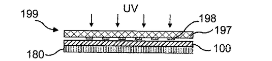
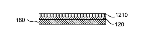
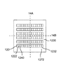
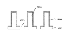
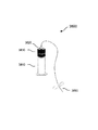
図1A〜図1Eは、本発明の実施形態に係るマイクロフィルタ120の製造プロセスにおける複数の段階を示す断面図である。図2Aは、本発明の実施形態に係るマイクロフィルタの製造プロセス200を示すフローチャートである。以下、図1A〜図1Eを参照しながら、図2Aの例示的なプロセスについて説明する。また、図3A〜図8Bを参照しながら、図2Aに示すプロセスの他の実施形態について後述する。
1A to 1E are cross-sectional views illustrating a plurality of stages in the manufacturing process of the
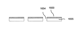
図2Aのブロック220において、基板180上に配されたエポキシ系の光画定可能な乾燥膜100(本明細書では「乾燥膜100」と呼ぶこともある)の層が準備される。いくつかの実施形態では、ブロック220において、基板180上に乾燥膜100が被せ(laminate)られる。ある実施形態では、ブロック220において、シリコンウェハに銅のような薄い金属材料層がコーティングされ、金属材料上に乾燥膜100が被せられる。他の実施形態では、ブロック220において、基板180にすでに付着された乾燥膜100が取得され、準備されてもよい。本明細書では、「エポキシ系の光画定可能な」物質とは、多機能性のエポキシ樹脂、ビスフェノールAエポキシ樹脂、エポキシ化された多官能ビスフェノールAホルムアルデヒドノボラック樹脂などの光画定可能なエポキシ樹脂を含むか、またはこのようなエポキシ樹脂から形成された、物質をさす。米国特許第7,449,280号明細書、同第6,716,568号明細書、同第6,391,523号明細書および同第6,558,868号明細書に、光画定可能なエポキシ樹脂の例が示されており、同文献の内容全体は、本明細書に参照により援用されたものとする。また、米国特許出願公開第2010/0068648号明細書および同第2010/0068649号明細書にも、光画定可能なエポキシ樹脂の例が示されており、同文献の内容全体は、本明細書に参照により援用されたものとする。本明細書では、「エポキシ系の光画定可能な乾燥膜」とは、エポキシ系の光画定可能な物質を含むか、またはこのような物質から形成された、乾燥膜である。米国特許第7,449,280号明細書、同第6,391,523号明細書および同第6,558,868号明細書、ならびに米国特許出願公開第2010/0068648号明細書および同第2010/0068649号明細書に、本発明の実施形態により使用されてもよいエポキシ系の光画定可能な乾燥膜の例が示されている。エポキシ系の光画定可能な乾燥膜は、ここで説明したものに限定されない。
In
基板上に塗布される前のエポキシ系の光画定可能な乾燥膜の液状レジストフォームは、基板上にスピンコートされ、基板上に乾燥膜を得るために乾燥されることができる。 The epoxy-based photodefinable dry film liquid resist foam before being applied onto the substrate can be spin coated onto the substrate and dried to obtain a dry film on the substrate.
特定の実施形態において、基板180は薄い銅箔である。いくつかの実施形態において、乾燥膜が被せられる基板表面の不規則性は、乾燥膜表面に転写されてしまうため、基板は滑らかであることが好ましい。いくつかの実施形態において、比較的短い時間で基板が除去されうるように、基板として薄い銅膜が好ましい。他の実施形態において、基板180は、シリコンウェハ、Kaptonなどのポリイミド膜または任意の他の適切な材料であってもよい。
In certain embodiments, the
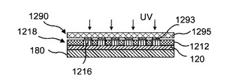
図1Bおよび図1Cに示されているように、ブロック240において、乾燥膜100が、マスク199を通してエネルギーにより露光され、露光済み乾燥膜110を形成する。図1Bおよび図1Cに示す実施形態において、UV光に対して透明なマスク部分197と、UV光に対して不透明な材料の薄膜で形成されたマスクパターン198と、を有する光学マスク199を通る紫外線(UV)光の形態のエネルギーにより、乾燥膜100が露光される。別の実施形態では、乾燥膜100は、ブロック240において、光学マスク199を通るUV光により露光される代わりに、X線マスクを通るX線により露光されてもよい。
As shown in FIGS. 1B and 1C, at
図1A〜図1Eに示す実施形態において、エポキシ系の光画定可能な乾燥膜100はネガ型レジストである。「ネガ型レジスト」とは、本明細書では、UV光やX線などのある種のエネルギーにより露光されると重合状態になる光画定可能な物質である。本発明の実施形態により使用されてもよいネガ型レジストエポキシ系の光画定可能な乾燥膜の例は、本発明の実施形態に従って使用され得る。
In the embodiment shown in FIGS. 1A-1E, the epoxy-based photodefinable
図1Cに示されているように、マスク199を通してUV光により露光された露光済み乾燥膜110の部分は重合状態になるが、部分116は非重合状態のままである。露光済み乾燥膜100の重合化部分および非重合化部分は、光学マスク199によって画定されたパターン118を形成する。特に、露光済み乾燥膜110のパターン118は、光学マスク199のパターン198によって画定され、パターン198は、UV光に対して不透明な材料によって形成される。ある実施形態において、パターン198は、クロム薄膜など、UV光に対して不透明な材料の薄膜によって形成されてもよい。
As shown in FIG. 1C, the portion of the exposed
別の実施形態において、ネガ型乾燥膜の代わりに、ポジ型のエポキシ系の光画定可能な乾燥膜が使用されてもよい。このような実施形態において、ポジ型乾燥膜からマイクロフィルタを形成するプロセスは、図4A〜図4Dに関連して以下に記載されているように、異なるマスクが使用されてもよい点を除いて、図1A〜図2Aに関連して記載したマイクロフィルタの形成プロセスと同様である。本明細書では、「ポジ型レジスト」とは、UV光やX線などのある種のエネルギーにより物質が露光されると、重合結合が破壊される光画定可能な物質である。ある実施形態において、ポジ型レジストは、ポリジメチルグルタルイミド(MicroChemから入手可能なPMGI、LORなど)、アセテートおよびキシレンフリーのレジスト(Shipley Corp.から入手可能なS1800(登録商標)シリーズのレジストなど)または別のタイプのポジ型レジストをベースにしたレジストであってもよい。厚さが数ミクロンを超えるレジスト層の場合、ネガ型レジストは、一般に、ポジ型レジストより感応性が高い。ほとんどの高分子レジストは、ポジ型レジスト膜のカテゴリーに属する。使用されてもよい乾燥膜ポジ型レジストの例は、ポリメチルメタクリレート(PMMA)、メチルメタクリレートの合成高分子を含む。ポジ型レジストの他の例は、アクリル類、ポリイミド、ポリエチレンテレフタレート(PET)(MYLAR(商標))などのポリエステル類がある。ある実施形態では、本発明の実施形態に従って、エポキシ系でない光画定可能な乾燥膜からマイクロフィルタが形成されてもよい。このような実施形態において、乾燥膜は、ポジ型またはネガ型のレジストであってもよい。他の実施形態において、マイクロフィルタは、乾燥膜ではなく光画定可能な液体から形成されてもよい。このような実施形態において、光画定可能な液体は、ポジ型レジストまたはネガ型レジストであってもよい。ある実施形態において、光画定可能な液体は、液状ポリイミドであってもよい。このような実施形態において、光画定可能な液状ポリイミドは、ポジ型レジストまたはネガ型レジストであってもよい。液体レジストは、基板上にスピンコーティングされ、基板上に乾燥膜を形成するように乾燥される。 In another embodiment, a positive epoxy based photodefinable dry film may be used instead of a negative dry film. In such an embodiment, the process of forming a microfilter from a positive dry film, except that different masks may be used, as described below in connection with FIGS. 4A-4D. , Similar to the process of forming the microfilter described in connection with FIGS. 1A-2A. As used herein, a “positive resist” is a photodefinable material that breaks the polymer bond when the material is exposed to some type of energy, such as UV light or X-rays. In some embodiments, the positive resist is polydimethylglutarimide (such as PMGI, LOR available from MicroChem), acetate and xylene free resist (such as the S1800® series resist available from Shipley Corp.). Alternatively, a resist based on another type of positive resist may be used. For resist layers with thicknesses greater than a few microns, negative resists are generally more sensitive than positive resists. Most polymer resists belong to the positive resist film category. Examples of dry film positive resists that may be used include polymethyl methacrylate (PMMA), a synthetic polymer of methyl methacrylate. Other examples of positive resists include acrylics, polyimides, and polyesters such as polyethylene terephthalate (PET) (MYLAR ™). In certain embodiments, the microfilter may be formed from a photodefinable dry film that is not epoxy-based, according to embodiments of the present invention. In such an embodiment, the dry film may be a positive or negative resist. In other embodiments, the microfilter may be formed from a photodefinable liquid rather than a dry film. In such embodiments, the photodefinable liquid may be a positive resist or a negative resist. In certain embodiments, the photodefinable liquid may be a liquid polyimide. In such an embodiment, the photodefinable liquid polyimide may be a positive resist or a negative resist. The liquid resist is spin-coated on the substrate and dried to form a dry film on the substrate.
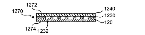
ブロック260において、マイクロフィルタを貫通して延在する複数のアパーチャ122を有するマイクロフィルタ120が、露光済み乾燥膜110から形成される。ある実施形態において、マイクロフィルタ120は、エポキシ系の光画定可能な乾燥膜から形成された高分子層と、高分子層を貫通して延在する複数のアパーチャとを含む。本明細書に記載する本発明の実施形態の各々において、マイクロフィルタは、1つ以上の高分子層と、1つ以上の高分子層の各々を貫通して延在する1つ以上のアパーチャとを含む。また、本明細書では、「アパーチャ」とは、層または他の構造体の外面間を延在する任意のタイプの通路、孔、トレンチ、ギャップ、穴などをさす。図1A〜図1Eに示す実施形態において、アパーチャ122は孔122である。
At
図1A〜図1Eに示す実施形態において、非重合化部分116を除去して、孔122を有するマイクロフィルタ120を形成するために、露光済み乾燥膜110が現像される。ある実施形態において、露光済み乾燥膜110は、乾燥膜100に現像剤を適用して非重合化部分116を溶解することによって現像される。いくつかの実施形態において、現像剤は、露光済み乾燥膜110が現像剤に浸漬されると、非重合化部分116を溶解する水溶液である。ブロック280において、孔122を有するマイクロフィルタ120は、図1Eに示すように、自立したマイクロフィルタ120を形成するように基板180から除去される。いくつかの実施形態において、マイクロフィルタは、構造体の外面間を延在する1つ以上のアパーチャを含む1つ以上の高分子層の構造体であり、この構造体は、1つ以上のアパーチャを通過する液体を濾過するのに十分な強度および柔軟性を有する。ある実施形態において、マイクロフィルタは、体液または体液を含む液体がフィルタを通過するとき、体液細胞の1つ以上のタイプがアパーチャを通過できないような小さな寸法を有するアパーチャを含んでいてもよく、アパーチャの寸法はまた、体液細胞の1つ以上の他のタイプがフィルタを通過できないほど小さいものである。本明細書では、「体液細胞」とは、赤血球や白血球、あるいはCTCや胎児細胞などの大きく希少細胞、循環内皮細胞等を含む、患者の体液中に見られる任意の細胞をさす。1つは、骨片を除去し液体の形をもたらすプロセスのあと、骨髄から腫瘍細胞を得ることができる。いくつかの実施形態において、マイクロフィルタは、多数の赤血球を通過させ、多数のCTCを通過させないサイズのアパーチャを含む。ある実施形態において、エポキシ系の光画定可能な乾燥膜の1つ以上の層から形成されたマイクロフィルタは、高分子マイクロフィルタであってもよい。
In the embodiment shown in FIGS. 1A-1E, the exposed
以下、図2B〜図8Bとの関係において、図2Aに示すプロセスのさまざまな実施形態について説明する。上述したように、ある実施形態では、基板180は銅箔であってもよい。このような実施形態では、ブロック280の1つの変形例として、硝酸、塩化鉄または別の既知の試薬を用いて、マイクロフィルタ120から銅基板180が除去されてもよい。ある実施形態において、試薬は、銅基板180をマイクロフィルタ120から除去する目的で、銅基板180をエッチング除去するために使用されてもよい。他の実施形態において、基板180は、アルミニウムなどの別のタイプの金属箔であってもよく、ブロック280において、既知の方法で除去されてもよい。
In the following, various embodiments of the process shown in FIG. 2A will be described in relation to FIGS. 2B-8B. As described above, in some embodiments, the
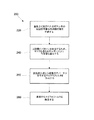
図2Bは、本発明の実施形態に係る、図2Aに示すブロック260において露光済み乾燥膜からマイクロフィルタを形成するプロセスを示すフローチャートである。ある実施形態において、マイクロフィルタの形成プロセス260は、露光済み乾燥膜から、複数のアパーチャを含む高分子層を形成するステップを含む。図2Bの実施形態では、ブロック262において、基板180上に配された露光済み乾燥膜110に、ポストベークプロセスが実行される。ある実施形態において、ポストベークプロセスは、乾燥膜110をポストベークするために、乾燥膜110を比較的高い温度にさらすステップを含む。ブロック264において、乾燥膜110は、図1A〜図1Eに対して上述した如く、現像剤を乾燥膜110に適用することによって現像される。ブロック266において、現像済み乾燥膜110に、ハードベークプロセスが実行される。ある実施形態において、ハードベークプロセスは、乾燥膜110を比較的高い温度にさらすステップを含む。図2Bに示すプロセスのいくつかの実施形態において、ブロック266のハードベークプロセスは省略されてもよい。このような実施形態では、ブロック262において露光済み乾燥膜110をポストベークし、ブロック264において乾燥膜110を現像することにより、マイクロフィルタ120が形成される。図2Bに関連して説明した上記プロセスは、本明細書に記載した任意の実施形態について使用することができる。さらに、本明細書に記載した本発明の任意の実施形態において、エポキシ系の光画定可能な乾燥膜からマイクロフィルタの高分子層を形成するプロセスは、上述したように、乾燥膜をエネルギーにより露光するステップ、ポストベークプロセスを実行するステップ、露光済み乾燥膜を現像するステップ、および/または、露光済み乾燥膜をポストベークするステップを含むことができる。
FIG. 2B is a flowchart illustrating a process for forming a microfilter from an exposed dry film in
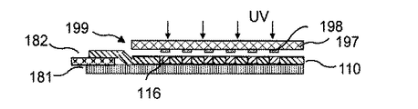
図3A〜図3Eは、本発明の実施形態に係る、マイクロフィルタ120の製造プロセスにおける複数の段階を示す断面図である。図3A〜図3Eに示す実施形態において、基板はポリイミド膜181である。ブロック220において、ポリイミド膜181上に配されたエポキシ系の光画定可能な乾燥膜100の層には、乾燥膜100の部分とポリイミド膜181との間に配置されたセパレータ182が設けられる。図3Aに示す実施形態では、乾燥膜100の縁に沿って、乾燥膜100の部分とポリイミド膜181との間にセパレータ182が形成されている。ある実施形態では、セパレータ182は、乾燥膜100の1つ以上の縁に沿って、または乾燥膜100とポリイミド膜181との間の他の場所に、設けられるものとしてもよい。セパレータ182は、ポリイミド膜(KAPTON膜など)により形成することもできるし、あるいは乾燥膜100に積層できてハードベークプロセスの温度に耐えられる他の任意の適切な材料により形成することもできる。
3A to 3E are cross-sectional views illustrating a plurality of stages in the manufacturing process of the
図3B〜図3Cに示すように、図1B〜図1Dに関連して上述した如く、ブロック240および260において、乾燥膜100がエネルギーにより露光され、マイクロフィルタ120が露光済み乾燥膜110から形成される。ある実施形態においては、マイクロフィルタ120は、複数のアパーチャが貫通した高分子層を含む。図3A〜図3Eに示す実施形態では、セパレータ182の露出端部を把持し、セパレータ182を用いてマイクロフィルタ120をポリイミド膜181から引き剥がすことにより、マイクロフィルタ120をポリイミド膜181から除去する。図3Dに示すようにポリイミド層181から乾燥膜100を除去した後、図3Eに示すように、セパレータ182を乾燥膜100から除去して、自立したマイクロフィルタ120を得る。層181からマイクロフィルタ120を除去するステップ、およびマイクロフィルタ120からセパレータ182を除去するステップは、本発明の実施形態に係るブロック280の、1つの変形例において実行される2つのステップである。
As shown in FIGS. 3B-3C, the
図2Aに示すプロセスの別の実施形態において、乾燥膜100の代わりに、液体レジストが使用されてもよい。このような実施形態では、ブロック210の1つの変形例として、金属物質の薄い層で基板をコーティングし、当該金属物質にエポキシ系液体フォトレジストをスピンコーティングして、基板上に配されたエポキシ系の光画定可能な物質の層を準備する。ある実施形態では、基板はシリコンウェハであってもよく、金属物質は銅であってもよく、液体フォトレジストはエポキシ系の光画定可能な液体であってもよい。いくつかの実施形態において、エポキシ系の光画定可能な液体は、SU−8などの液体ネガ型レジストである。図1B〜図1Dに対して上述したように、ブロック240および260において、エポキシ系の光画定可能な物質の層は、エネルギーにより露光され、露光済み層からマイクロフィルタ120が形成される。上述したように、ブロック280の1つの変形例として、従来のプロセスを用いて金属物質をエッチング除去することにより、基板からマイクロフィルタ120が剥離される。ある実施形態において、液体レジストは、SU−8またはMicroChem Corp.から入手可能なKMPR(登録商標)などの、液体ネガ型レジストであってもよい。
In another embodiment of the process shown in FIG. 2A, a liquid resist may be used instead of the
図2Aに示すプロセスの他の代替的な実施形態では、乾燥膜100の代わりに液体ネガ型レジストが使用されてもよく、剥離層としてネガ型レジストと基板との間にポジ型レジストが使用されてもよい。このような実施形態では、ブロック210の1つの変形例として、基板上にエポキシ系の光画定可能な物質の層を形成するため、基板上に液体ポジ型レジストがスピンコーティングされ、当該ポジ型レジストがコーティングの厚さに応じた適切な照射量のエネルギー(UV光など)により露光され、次に当該ポジ型レジスト上に液体エポキシ系ネガ型レジストがスピンコーティングされる。ある実施形態において、ポジ型レジストは、マスクを使用することなくエネルギーにより露光されてもよい。エポキシ系の光画定可能な物質の層は、エネルギーにより露光され、図1B〜図1Dに対して上述したように、マイクロフィルタ120が、ブロック240および260において露光済み層から形成される。このような実施形態では、ブロック280の1つの変形例として、ポジ型レジストを現像することによって、基板からマイクロフィルタ120が剥離される。ある実施形態において、同じ現像剤が、ポジ型レジストとネガ型レジストの両方を現像するために使用されてもよい。他の実施形態において、1つの現像剤が、マイクロフィルタ120に孔を形成するために使用され、別の現像剤が、基板からマイクロフィルタを剥離するために使用されてもよい。別の実施形態において、液体ポジ型レジストの代わりに、剥離層として乾燥膜ポジ型レジストが使用されてもよい。使用されてもよい乾燥膜ポジ型レジストの例として、ポリメチルメタクリレート(PMMA)およびメチルメタクリレートの合成高分子がある。
In another alternative embodiment of the process shown in FIG. 2A, a liquid negative resist may be used in place of the
他の実施形態において、ポジ型レジスト剥離層と組み合わせて、ネガ型エポキシ系の光画定可能な乾燥膜100が使用されてもよい。このような実施形態は、ブロック210において液体ネガ型レジストのスピンコーティングをするのではなくスピンコーティングされたポジ型レジスト上にネガ型乾燥膜100の層を被せてもよい点を除き、ポジ型レジスト剥離層を利用した上述の実施形態と同様である。
In other embodiments, a negative epoxy based photodefinable
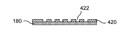
図4A〜図4Dは、本発明の実施形態に係る、マイクロフィルタ420の製造プロセスにおける複数の段階を示す断面図である。図4A〜図4Dに示す実施形態では、ブロック220において、基板180上に配されたポジ型エポキシ系の光画定可能な乾燥膜400(本明細書において「乾燥膜400」と呼ぶこともある)の層が準備される。ある実施形態では、ブロック220において、基板180上にポジ型乾燥膜400が被せられる。図4Bに示すように、図1Bおよび図1Cに対して上述した如く、ブロック240において、ポジ型乾燥膜400がエネルギーにより露光される。ただし、乾燥膜400の露光された部分が重合状態になるのではなく、マスク499を通過したエネルギー(例えば、UV光)により露光される部分416において乾燥膜400の重合結合が破壊される点が異なる。露光済み部分416と非露光部分とで構成されるパターン418が、露光済み乾燥膜410に形成される。図4Bに示すように、マスク499は、透明部分497と、不透明部分498とを含む。上述したように、図1Bのマスク199は、ネガ型レジストとともに使用され、乾燥膜100のうち孔が形成されることとなる部分を覆うように構成されている。図4A〜図4Dに示す実施形態では、マスク499の不透明部分498は、ポジ型乾燥膜400の、アパーチャが形成されることとなる場所を除く全ての部分を覆うように構成されており、これにより、UV光は、ポジ型乾燥膜400のうちアパーチャが形成されるべき部分へとマスク499を通過することができる。
4A to 4D are cross-sectional views illustrating a plurality of stages in the manufacturing process of the
図4A〜図4Dに示す実施形態におけるブロック260の1つの変形例として、重合結合が破壊された乾燥膜400の部分416を溶解する現像剤を使用して乾燥膜410を現像することによって、露光済み乾燥膜410からマイクロフィルタ420が形成される。図4Dに示すように、ブロック280において、独立した高分子マイクロフィルタ420を形成するため、アパーチャ422を有するマイクロフィルタ420が基板180から除去される。いくつかの実施形態では、マイクロフィルタ420は、エポキシ系の光画定可能な乾燥膜から形成された高分子層を含み、高分子層を貫通して延在する複数のアパーチャを含む。ある実施形態では、アパーチャ422は孔422である。いくつかの実施形態では、ブロック280において、上述したようにポジ型レジストを現像することによりマイクロフィルタ420が基板から剥離されてもよい。
As a variation of
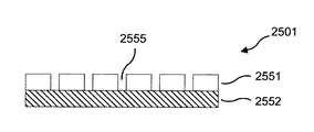
図5A〜図5Dは、本発明の実施形態に係る、エポキシ系の光画定可能な乾燥膜の複数の層から複数のマイクロフィルタを製造するプロセスにおける複数の段階を示す断面図である。図2Aに示すプロセスについてのある実施形態では、ブロック220において、基板580上に配されたエポキシ系の光画定可能な乾燥膜500(本明細書において「乾燥膜500」と呼ぶこともある)の層をそれぞれ含む、複数の乾燥膜構造体501が準備される。図5A〜図5Dに示す実施形態では、図5Aに示すように、支持体590上に構造体501を積層することにより、ブロック220において基板580上に配された乾燥膜500が準備される。
5A-5D are cross-sectional views illustrating multiple stages in a process for manufacturing a plurality of microfilters from a plurality of layers of an epoxy-based photodefinable dry film, according to an embodiment of the present invention. In one embodiment for the process shown in FIG. 2A, at
ある実施形態では、図5Aに示すように、構造体501の積層体に含まれる複数の乾燥膜500が、図2Aのブロック240において、X線マスク599を通るX線の形態のエネルギーにより同時に露光される。いくつかの実施形態では、X線はUV光よりかなり深く浸透する。X線は、UV光とは異なり、5mm未満の厚さを有する材料内であれば1ミクロンより著しく小さい形状に対しても発散しない。いくつかの実施形態では、典型的に、シンクロトロンのビームライン上でX線リソグラフィが実行されてもよい。また、X線リソグラフィは、ネガ型およびポジ型の両方のレジストに対しても使用されうる。図5A〜図5Dに示す実施形態において、乾燥膜500はそれぞれネガ型レジストである。他の実施形態において、乾燥膜500は、ポジ型レジストであってもよい。このような実施形態では、図4Bのマスク499に関して上述したのと同様に、ポジ型レジストにアパーチャを形成するよう構成されたマスクを使用することができる。さらに、乾燥膜500がポジ型レジストである実施形態では、乾燥膜500は、そのそれぞれを各基板上に配するのではなく、支持体590上に付着させて互いに直接積層することができる。
In some embodiments, as shown in FIG. 5A, a plurality of
図5Bに示すように、各乾燥膜500のうちマスク599を通してX線に露光される部分は重合状態になり、乾燥膜500の部分516は重合されないまま残る。各乾燥膜500の重合化部分および非重合化部分は、光学マスク599のパターン598によって規定されたパターン518を形成する。いくつかの実施形態では、マスク599は、X線に対し透明な部分597と、X線を実質的にブロックするよう構成されたパターン598とを含む。ある実施形態において、パターン598は金により形成される。また、いくつかの実施形態において、X線に対し透明部分597は、薄いグラファイトシートまたはシリコンウェハであってもよい。図5A〜図5Dに示す実施形態において、基板580は、それぞれ、当該基板に入射されたX線エネルギーのほとんどを透過する。ある実施形態では、基板580は金属箔により形成される。このような実施形態では、金属箔が十分に薄い場合、基板580は、それぞれ、当該基板に入射されたX線エネルギーのほとんどを透過する。いくつかの実施形態では、積層され、同時に露光されてもよい構造体501の数は、金属箔を通過するX線に生じるX線の照射量の減衰に基づいて定められる。
As shown in FIG. 5B, a portion of each
ある実施形態では、ブロック260の1つの変形例として、複数の露光済みの乾燥膜510は、図1A〜図1Eに関連して上述したのと同様の方法で、各々がアパーチャ522を有する複数のマイクロフィルタ520を形成するように現像される。ある実施形態では、アパーチャ522は孔522である。いくつかの実施形態では、図5Bおよび図5Cに示すプロセスは、ブロック260の1つの変形例において実行されてもよい。このような実施形態では、構造体501は、図5Bに示すように互いから分離され、ブロック262の1つの変形例において、それぞれの基板580上に配された露光済み乾燥膜510に対しポストベーク処理が実行される。ある実施形態では、露光済み乾燥膜510の各々は、図5Cに示すように、乾燥膜500の各々に孔522を形成するために、ブロック264の1つの変形例において、上述したように現像される。いくつかの実施形態では、孔522を有するマイクロフィルタ520を形成するために、ブロック266の1つの変形例において、それぞれの基板580上に配された乾燥膜510に対しハードベーク処理が実行される。他の実施形態において、ハードベーク処理は省略されてもよい。ある実施形態では、ブロック280の1つの変形例において、図5に示す如く、孔522を有する独立したマイクロフィルタ520を得るため、上述したようにマイクロフィルタ520から基板580が化学的に除去される。ある実施形態では、マイクロフィルタ520はそれぞれ、アパーチャ522を含む高分子層である。
In one embodiment, as one variation of
上述したように、ある実施形態では、基板580の各々は、金属箔から形成されてもよい。別の実施形態において、基板580は、基板に適用されるX線のほとんどを透過し、かつ、乾燥膜500のポストベーク温度より高い融点を有する、高分子系の基板であってもよい。例えば、ある実施形態において、基板580は、ポジ型レジストから形成されてもよい。このような実施形態では、基板580は、図2Aのブロック280において、現像液により基板580が化学的に除去されるように、ポジ型レジストの重合結合を破壊するのに十分なエネルギー、例えば、UV光やX線などにより露光されてもよい。他の実施形態において、基板580はポリイミド膜であってもよく、当該基板は、ブロック280においてマイクロフィルタ520からポリイミド基板580を剥離することによって、除去されてもよい。
As described above, in some embodiments, each of the
別の実施形態では、エポキシ系の光画定可能な乾燥膜500(本明細書において「乾燥膜500」と呼ぶこともある)の複数の層は、各層がそれぞれの基板上に配され積層されることなく、同時に露光されてもよい。このような実施形態では、乾燥膜500は、ブロック220の1つの変形例において、隣接する乾燥膜500間に基板を配置せずに支持体590上に積層される。積層された乾燥膜500は、ブロック240の1つの変形例において露光される。いくつかの実施形態において、図2Bに示すプロセスは、ブロック260において実行されてもよい。このような実施形態では、露光済み乾燥膜510は分離されて個別の基板上に置かれ、ブロック262の1つの変形例において、これら個別の基板上の露光済み乾燥膜510に対してポストベークプロセスが実行される。このような実施形態では、使用される基板は、ポストベーク温度に耐えることができ、かつ、水または1つ以上の化学物質によって溶解できるものとする。露光済み乾燥膜510は、それぞれの基板に付着された状態で、ブロック264において現像され、ブロック266においてハードベーク処理されるものとしてもよい。ブロック280において、基板580は、露光済み乾燥膜510から形成されたマイクロフィルタ520から除去される。
In another embodiment, a plurality of layers of epoxy-based photodefinable dry film 500 (sometimes referred to herein as “
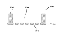
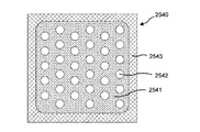
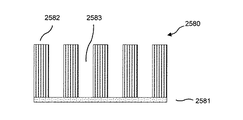
ある実施形態において、構造体501は、接着剤、クランプまたは任意の他の適切な機構や方法を用いて、支持体590に付着されてもよい。いくつかの実施形態において、構造体501は、静電チャックによって支持体に保持される。図6Aおよび図6Bは、本発明の実施形態に係るマイクロフィルタの形成プロセスにおける、静電チャック装置600を使用して支持体に乾燥膜構造体501を付着するプロセスの複数の段階を示す断面図である。図6Aおよび図6Bに示す実施形態において、複数の乾燥膜構造体501は、その各々が基板580上に配されたエポキシ系の光画定可能な乾燥膜500の層を含んでおり、図6Aに示すように、支持体690上に積層されて準備される。図6Aに示すように、支持体690は、ダクト693を有する水冷フレーム692と、フレーム692上に配された絶縁体664と、絶縁体664上に配された導電層662とを含む。また、図6Aに示すように、構造体501の積層体上に透明導電層660が配され、導電層660と662との間に構造体501の積層体が配される。また、図6Aに示すように、導電層間を接続する回路は開状態であり、導電層に印加される電圧665はゼロとなっている。
In certain embodiments, the
図6Bに示すように、導電層間の回路を閉じ、ゼロでない電圧665が導電層660と662との間に印加されると、装置600は、導電層660と662との間で構造体501を押圧することとなる。装置600によって構造体501が押圧された状態において、図5A〜図5Dに関連して上述した如く、X線マスク599を介して乾燥膜500にX線を照射してもよい。ある実施形態では、図6Aおよび図6Bに関連して上述した如く、装置600上で構造体501を積層し、装置600を使用して構造体501を一緒に押圧することは、図2Aのブロック220の1つの変形例において実行されてもよい。各基板上に配された乾燥膜からマイクロフィルタを形成することに関連して静電チャック装置の使用について上述したが、別の実施形態では、静電チャックを同様に用いて、各基板上に配されていない自立した乾燥膜のような、自立した高分子膜の積層体を押圧してもよい。このような自立した複数の乾燥膜は、複数の乾燥膜から複数のマイクロフィルタを形成するプロセス中において、互いに積層され一緒に押圧されてもよい。
As shown in FIG. 6B, when the circuit between the conductive layers is closed and a
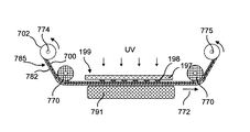
図7Aおよび図7Bは、本発明の実施形態に係る、乾燥膜構造体のロールからマイクロフィルタを製造するプロセスにおける複数の段階を示す断面図である。図7Aおよび図7Bに示す実施形態では、乾燥膜構造体785は、当該乾燥膜構造体785のロール702の形態で準備される。乾燥膜構造体785は、除去可能な基板782上に配されたエポキシ系の光画定可能な乾燥膜700(本明細書において「乾燥膜700」と呼ぶこともある)の層を含む。いくつかの実施形態において、基板782は、化学的に溶解可能な金属箔であってもよい。ある実施形態において、金属箔は、アルミニウムまたは銅を含んでもよく、上述したようにエッチング除去されてもよい。図7Aおよび図7Bに示す実施形態において、ローラ774にロール702の一方が配置され、ローラ775に他方が配置される。乾燥膜構造体785の作業部分787は、ローラ774と775との間で延伸され、ローラ770によって実質的に平坦に保持されて、マスク199を通るエネルギーにより露光される。
7A and 7B are cross-sectional views illustrating multiple stages in a process for manufacturing a microfilter from a roll of dry film structure, according to an embodiment of the present invention. In the embodiment shown in FIGS. 7A and 7B, the
図2Aに示すプロセスのある実施形態では、ブロック220の1つの変形例において、ロール702から乾燥膜構造体785の一部分を展開して矢印772の方向に構造体785の当該部分を前進させ、支持体791とマスク199との間に構造体785の作業部分787を設けることにより、基板782上に配されたエポキシ系の光画定可能な乾燥膜700の層が準備される。いくつかの実施形態において、ブロック220において設けられる作業部分787は、マスクを介したエネルギーの露光によるパターン化が行われていない乾燥膜700の部分を含んでいる。ある実施形態において、支持体791およびマスク199は、構造体785が前進されるときは、構造体785から離れる方向に移動される。
In one embodiment of the process shown in FIG. 2A, in one variation of
図7Aおよび図7Bに示す実施形態では、図2Aのブロック240の1つの変形例において、図7Bに示すように、マスク199および支持体791は、構造体785に隣接した位置に移動され、乾燥膜700は、マスク199を介してエネルギーにより露光される。図7Aおよび図7Bに示す実施形態において、マスク199は光学マスクであり、エネルギーはUV光であるが、上述したように、異なるマスクとともに、異なるタイプのエネルギーが使用されてもよい。図7Aおよび図7Bに示す実施形態において、乾燥膜700はネガ型レジストである。他の実施形態において、乾燥膜700はポジ型レジストであってもよい。このような実施形態では、図4Bのマスク499に関連して上述した如く、ポジ型レジストに孔を形成するように構成されたマスクが使用されてもよい。他の実施形態に関連して上述したように、マスクを介してエネルギーにより乾燥膜700を露光すると、乾燥膜700にパターンが形成される。ある実施形態において、支持体791は、図7Bに示すように、構造体785を押圧し、露光プロセスに備えて乾燥膜700を引き伸ばし、これにより乾燥膜700に対し露光プロセス中にさらなる張力と安定性を与える。いくつかの実施形態では、乾燥膜700を露光した後、構造体785は、ブロック220において露光されていない新しい作業部分787を準備するように、上述した如く再び前進されてもよく、新しい作業部分787は、上述した如くブロック240において露光されてもよい。ある実施形態において、構造体785を前進させて乾燥膜700を露光するこのプロセスは、継続的に繰り返されてもよい。いくつかの実施形態において、本プロセスは、乾燥膜700のほとんどまたはすべての部分が露光プロセスを受けるまで、繰り返されてもよい。
In the embodiment shown in FIGS. 7A and 7B, in one variation of
いくつかの実施形態では、ブロック260の1つの変形例において、他の実施形態に関連して上述した如く、露光部分を現像することにより乾燥膜700の露光部分からアパーチャを有するマイクロフィルタが形成される。このような実施形態では、乾燥膜700の露光部分は、ローラ775に巻かれる前に現像されてもよく、または乾燥膜700のすべての所望の部分が露光された後に現像されてもよい。いくつかの実施形態において、図2Bに示すプロセスは、ブロック260において実行されてもよい。このような実施形態では、乾燥膜700の露光部分は、ブロック262においてポストベーク処理用の炉を通って前進されてもよく、乾燥膜700の露光部分は、ブロック264において現像された後、ブロック266においてハードベーク処理を受けてもよい。他の実施形態において、ブロック262、264、および266での処理は、乾燥膜700のすべての所望の部分が露光された後に実行されてもよい。ある実施形態において、ハードベーク処理は省略されてもよい。
In some embodiments, in one variation of
いくつかの実施形態において、露光済み乾燥膜700を現像した後、基板782は、他の実施形態に関連して上述した如く、ブロック280において除去される。ある実施形態では、基板782を除去した後、マイクロフィルタを形成した乾燥膜のロールから、個々のマイクロフィルタが切り出される。ある実施形態では、ロールとして準備された乾燥膜からマイクロフィルタを形成することで、本発明の実施形態に係るマイクロフィルタの製造が単純化され、製造プロセスの自動化が可能になりうる。
In some embodiments, after developing the exposed
図8Aおよび図8Bは、本発明の実施形態に係る、乾燥膜構造体の複数のロールからマイクロフィルタを製造するプロセスにおける複数の段階を示す断面図である。図8Aおよび図8Bに示す実施形態は、複数のロール702のエポキシ系の光画定可能な乾燥膜700の層がエネルギーにより同時に露光される点以外、図7Aおよび図7Bに示す実施形態と同様である。このような実施形態では、矢印772の方向に各ロール702の構造体785を前進させて支持体891とマスク899との間に構造体785の積層体887を供給することにより、ブロック220の1つの変形例において、各基板782上にそれぞれ配されたエポキシ系の光画定可能な乾燥膜700の複数の層が準備される。図8Aおよび図8Bに示す実施形態において、マスク899および支持体891は、積層体887に隣接する位置へ移動され、マスク899と支持体891との間に配された積層体887の乾燥膜700の部分は、図2Aのブロック240の1つの変形例において、図8Bに示すように、マスク899を通してエネルギーにより同時に露光される。図8Aおよび図8Bに示す実施形態において、乾燥膜700の各々はネガ型レジストである。他の実施形態において、乾燥膜700はポジ型レジストであってもよい。このような実施形態では、図4Bのマスク499に関連して上述した如く、ポジ型レジストにアパーチャを形成するように構成されたマスクが使用されてもよい。乾燥膜700からマイクロフィルタを形成するさらなるプロセスは、図7Aおよび図7Bに示す実施形態に関連して上述したプロセスと同様である。
8A and 8B are cross-sectional views illustrating multiple stages in a process of manufacturing a microfilter from multiple rolls of a dry membrane structure, according to an embodiment of the present invention. The embodiment shown in FIGS. 8A and 8B is similar to the embodiment shown in FIGS. 7A and 7B, except that the layers of the epoxy-based photodefinable
図8Aおよび図8Bに示す実施形態において、ダクト693を含む水冷フレーム692上に支持体891が配される。また、図8Bに示すように、構造体785の作業部分887は、クランプ860によって支持体891とマスク899との間の適所に確実に保持されてもよい。別の実施形態において、積層体887は、他の実施形態に関連して上述した如く、静電チャックを使用して確実に保持されてもよい。いくつかの実施形態において、同時に露光される乾燥膜700の数は、特定の数の膜の積層体を露光するときに生じる精度に基づいて決定されてもよい。ある実施形態では、上述したように複数のロールとして準備された複数の乾燥膜からマイクロフィルタを形成することで、マイクロフィルタの製造が単純化され、および/または、マイクロフィルタの大量生産が容易になりうる。
In the embodiment shown in FIGS. 8A and 8B, a
非エポキシ系乾燥膜が使用される実施形態においては、乾燥膜は、基板がないロールの形態で準備されてもよい。このような実施形態では、各ロール702は、乾燥膜のみを含み、基板を含まない。エポキシ系乾燥膜が使用される実施形態では、各ロール702は、乾燥膜700上にさらなる被覆層を含んでもよい。このような実施形態では、基板782は、乾燥膜700の第1の面に配され、被覆層は、乾燥膜700の反対側の面に配される。ある実施形態では、本発明の実施形態に係るリソグラフィをベースにした微細加工により、高度に均一な精度のマイクロフィルタの効率的な大量生産が可能になりうる。ある実施形態では、本発明の実施形態に従ってマイクロフィルタを作製することにより、生産されるマイクロフィルタの多孔性および孔の均一性が高まりうる。
In embodiments where a non-epoxy dry film is used, the dry film may be provided in the form of a roll without a substrate. In such an embodiment, each
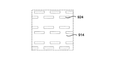
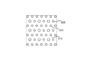
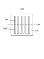
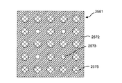
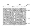
図9A〜図9Dは、本発明の実施形態に係る種々のマイクロフィルタの、アパーチャの分布を示す部分平面図である。ある実施形態において、異なるサイズ、形状、および分布を有するアパーチャを備えたマイクロフィルタが作製されてもよい。いくつかの実施形態では、マイクロフィルタの特定の応用に関しては、アパーチャのサイズ、形状、および分布の或る組み合わせが、他の組み合わせより有益なものとなりうる。例えば、血中の循環腫瘍細胞や胎児細胞などの希少細胞を精密濾過するために、ある実施形態では、各々の直径が7〜8ミクロンの円形孔を有するマイクロフィルタが好ましい場合がある。いくつかの応用においては、各々の直径が7〜8ミクロンの円形孔を有するマイクロフィルタが、非常にわずかな比率の血球を保持しながら、希少細胞を捕獲しうる。 9A to 9D are partial plan views showing the aperture distribution of various microfilters according to the embodiment of the present invention. In certain embodiments, microfilters with apertures having different sizes, shapes, and distributions may be made. In some embodiments, for certain applications of microfilters, certain combinations of aperture sizes, shapes, and distributions may be more beneficial than others. For example, in order to microfilter rare cells such as circulating tumor cells and fetal cells in the blood, in certain embodiments, a microfilter having a circular hole with a diameter of 7-8 microns each may be preferred. In some applications, microfilters with circular pores, each 7-8 microns in diameter, can capture rare cells while retaining a very small proportion of blood cells.
図9Aおよび図9Bに示す実施形態では、マイクロフィルタ910および912は、均一な分布の孔920および922を、それぞれ有する。また、孔920は、孔922と同様に、サイズが均一である。図9Cに示す実施形態では、マイクロフィルタ914は均一な孔924を含み、孔924はいくつかの群に分かれてマイクロフィルタ914内に分布している。図9Dに示す実施形態において、マイクロフィルタ916は、第1のサイズの複数の孔926と、第2のサイズの複数の孔928とを含む。他の実施形態では、孔920、922、924、926、および928のいずれか任意のものが、任意の他のタイプのアパーチャであってもよい。マイクロフィルタ910、912、914、および916のいずれか任意のものは、本発明の実施形態に係る上述したマイクロフィルタ製造プロセスの任意のものを使用して製造されてもよい。また、本発明の実施形態に係る上述したマイクロフィルタ製造プロセスの任意のものは、複数の異なる断面形状のアパーチャを形成するために使用されてもよい。例えば、ある実施形態においては、円形、三角形、正方形、長方形、長円形、楕円形、台形、平行四辺形などの断面形状を有するアパーチャが形成されてもよい。
In the embodiment shown in FIGS. 9A and 9B, the
さまざまな厚さを有し、かつ、さまざまな形状、サイズ、および分布のアパーチャを有するマイクロフィルタは、本明細書に記載する本発明の実施形態により製造されてもよい。図10A〜図10Dは、本発明の実施形態に係る、さまざまな厚さを有し、かつ、さまざまな形状、サイズ、および分布をもつアパーチャを備えた、マイクロフィルタの断面図である。図10Aおよび図10Bは、それぞれ本発明の実施形態に係る上述したプロセスの1つにより形成されたマイクロフィルタ1010および1012を示している。マイクロフィルタ1010は、各々が幅1040を有する複数の孔1020を含む。マイクロフィルタは、孔1020の幅1040に対してほぼ垂直な厚さ1030を有する。図10Aに示す実施形態において、厚さ1030は、幅1040より著しく大きいものではない。ある実施形態において、マイクロフィルタの厚さは、サンプルが孔を通過するのに必要な圧力を低減するために、マイクロフィルタの1つ又は複数の孔の幅とほぼ同じものであることが好ましい。いくつかの用途では、マイクロフィルタの厚さがいくつかの孔の幅または全ての孔の幅より著しく大きいと、マイクロフィルタの厚さがいくつかの又は全ての孔の幅とほぼ同じである場合に比べ、サンプルを、マイクロフィルタを通過させるため、当該マイクロフィルタに非常に大きな圧力をかけることとなる場合がある。比較的大きな圧力でサンプルをフィルタに押し通すと、1つ以上の孔の形状を変形させたり、マイクロフィルタを破損させる危険が生じ得る。
Microfilters having various thicknesses and apertures of various shapes, sizes, and distributions may be manufactured according to the embodiments of the invention described herein. 10A-10D are cross-sectional views of microfilters with apertures having various thicknesses and having various shapes, sizes, and distributions, according to embodiments of the present invention. 10A and
例えば、血中のCTCや胎児細胞などの希少細胞を精密濾過するために、ある実施形態では、厚さが8〜14ミクロンのマイクロフィルタが好ましい場合がある。ある実施形態では、このような用途のためのマイクロフィルタは、直径が7〜8ミクロンで厚さが8〜14ミクロンの孔を有してもよい。他の実施形態において、このような用途のためのマイクロフィルタは、5〜7ミクロンの幅および7ミクロンを超える長さを有する長方形のアパーチャを含んでもよい。ここで、アパーチャの長さおよび幅は、共にマイクロフィルタの厚さに対してほぼ垂直に測った長さである。ある実施形態において、長方形のアパーチャは細長いトレンチ(溝、trench)であってもよい。ある実施形態では、マイクロフィルタに設けられたアパーチャの幅は、そのサイズがマイクロフィルタの厚さに近いことが好ましい場合がある。いくつかの実施形態において、マイクロフィルタの厚さは、一部又は全部の孔の幅の10倍未満である。他の実施形態において、マイクロフィルタの厚さは、孔の一部またはすべての幅である10ミクロンの範囲内である。本発明の実施形態に従って形成されたマイクロフィルタは、血液から循環腫瘍細胞を捕獲する以外の応用において使用されてもよい。いくつかの実施形態において、所望のアパーチャの幾何学的形状、アパーチャ寸法、アパーチャ分布、マイクロフィルタの材料、マイクロフィルタの厚さ、マイクロフィルタのサイズなどは、用途に応じて異なるものであってもよい。いくつかの実施形態において、アパーチャについての所望の幾何学的形状、寸法、および分布は、光学マスクまたはX線マスクなどの適切なマスクを用いることで実現することができる。ある実施形態では、フィルタ材料の破損またはアパーチャ形状の変形を防ぐため、マイクロフィルタの素材強度が重要となり得る。 For example, in some embodiments, a microfilter with a thickness of 8-14 microns may be preferred to microfilter rare cells such as CTCs and fetal cells in the blood. In certain embodiments, microfilters for such applications may have pores that are 7-8 microns in diameter and 8-14 microns in thickness. In other embodiments, the microfilter for such applications may include a rectangular aperture having a width of 5-7 microns and a length greater than 7 microns. Here, the length and width of the aperture are both lengths measured substantially perpendicular to the thickness of the microfilter. In some embodiments, the rectangular aperture may be an elongated trench. In some embodiments, the width of the aperture provided in the microfilter may be preferably close in size to the thickness of the microfilter. In some embodiments, the thickness of the microfilter is less than 10 times the width of some or all of the holes. In other embodiments, the thickness of the microfilter is in the range of 10 microns, which is the width of some or all of the holes. Microfilters formed in accordance with embodiments of the present invention may be used in applications other than capturing circulating tumor cells from blood. In some embodiments, the desired aperture geometry, aperture dimensions, aperture distribution, microfilter material, microfilter thickness, microfilter size, etc. may vary depending on the application. Good. In some embodiments, the desired geometry, dimensions, and distribution for the aperture can be achieved by using an appropriate mask, such as an optical mask or an x-ray mask. In some embodiments, the material strength of the microfilter can be important to prevent breakage of the filter material or deformation of the aperture shape.
図10Bに示すように、マイクロフィルタ1012は、各々が幅1042を有する複数の孔1022を有する。マイクロフィルタ1012は、また、孔1022の幅1042に対してほぼ垂直な厚さ1032を有する。マイクロフィルタ1012の厚さ1032は、マイクロフィルタ1010の厚さより大きい。図10Bに示す実施形態において、孔1022は、サイズが均一であり、各々が、マイクロフィルタ1012の第1の表面1050および第2の表面1052に対してほぼ垂直である。図10Cに示す実施形態では、マイクロフィルタ1014は、第1の幅1044を有する孔1024と、第1の幅1044より小さい第2の幅1046を有する孔1026とを有する。また、マイクロフィルタ1014は、厚さ1034を有する。図10Dに示す実施形態では、マイクロフィルタ1016は、不均一の断面形状を有する孔1028を有する。各孔1028は、マイクロフィルタ1016の第1の表面1054にある第1の開口部と、マイクロフィルタ1016の第2の表面1056にある第2の開口部とを有する。図10Dに示すように、第1の表面1054にある孔1028の幅1048は、第2の表面1056にある孔1028の幅1049より大きい。また、マイクロフィルタ1016は、厚さ1036を有する。図10Eに示した実施形態では、マイクロフィルタ1018は、不均一な断面形状を有する孔1029を有する。各孔1029は、マイクロフィルタ1018の第1の表面1053における第1の開口部1045とマイクロフィルタ1018の第2の表面1057における第2の開口部1047を有する。図10Eに示すように、第1の表面1053における孔1029の幅1045は、第2の表面1057における孔1029の幅1047よりも小さい。マイクロフィルタ1018は厚さ1038も有する。
As shown in FIG. 10B, the
図12A〜図12Kは、本発明の実施形態に係る多層マイクロフィルタ1270の製造プロセスにおける複数の段階を示す断面図である。図12Lは、本発明の実施形態に係る多層マイクロフィルタ1270の平面図である。図11は、本発明の実施形態に係る多層マイクロフィルタ1420の製造プロセス1100を示すフローチャートである。図14Aおよび図14Bは、本発明の実施形態に係る多層マイクロフィルタ1420の断面図である。図14Cは、図14Aおよび図14Bに示す多層マイクロフィルタ1420の平面図である。以下、図12A〜図12Fおよび図14A〜図14Cを参照しながら、図11の例示的なプロセスについて説明する。図13Aおよび図13Bは、図11に示すプロセスにおける複数の段階を示す平面図である。
12A to 12K are cross-sectional views illustrating a plurality of stages in the manufacturing process of the
図11のブロック1120において、エポキシ系の光画定可能な乾燥膜の層から、基板180上に第1のマイクロフィルタ120が形成される。図12A〜図12Lに示す実施形態において、第1のマイクロフィルタ120は、ブロック280における基板180からのマイクロフィルタ120の除去を省略する上述の図2Aのプロセス200と同様のプロセスによって、基板180上に形成されてもよい。ある実施形態において、マイクロフィルタ120は、複数のアパーチャを含む高分子層で構成される。プロセス1100のある実施形態において、乾燥膜100に複数の孔を形成するよう構成されたパターン198を有するマスク199の代わりに、乾燥膜100に複数の細長いトレンチを形成するよう構成されたパターンを有するマスクが使用されてもよい。このような実施形態では、マスクは、細長い金属ストリップを含むパターンを有するものとすることができ、これにより、乾燥膜100が当該マスクを通して露光されると、対応する細長いトレンチが乾燥膜100に形成される。
In
図13Aは、本発明の実施形態に係る、ブロック1120において形成されたマイクロフィルタ120の平面図である。図13Aに示すように、マイクロフィルタ120は、複数の細長いトレンチ1222を含み、トレンチ1222を通して露光される基板180上に配される。図12Aは、図13Aの線12Aに沿って切り取ったマイクロフィルタ120の断面図であり、図12Bは、図13Aの線12Bに沿って切り取ったマイクロフィルタ120の断面図である。図示のように、線12Bは、線12Aに対して垂直である。
FIG. 13A is a plan view of the
図11のブロック1140において、図12Cに示すように、エポキシ系の光画定可能な乾燥膜1210(本明細書において「乾燥膜1210」と呼ぶこともある)の層をマイクロフィルタ120上に被せる。ある実施形態において、乾燥膜1210は、その下の表面に形成された構造物をつなぐ(bridging)ことができる。このような実施形態では、乾燥膜1210は、マイクロフィルタ120上に被せられる際には、トレンチ1222にほとんど入り込まない。後述するように、ブロック1160において、エポキシ系の光画定可能な乾燥膜1210の層から第2のマイクロフィルタ1230が形成される。ある実施形態において、マイクロフィルタ1230は、複数のアパーチャを含む高分子層により構成される。図12Dに示すように、図2Aのブロック240に関連して上述した如く、乾燥膜1210は、マスク1290を通してエネルギーにより露光され、重合化されたパターン1218と重合化されていない部分1216を有する露光済み乾燥膜1212を形成する。図12A〜図12Lに示す実施形態において、乾燥膜1210はネガ型レジストである。他の実施形態では、乾燥膜1210は、ポジ型レジストであってもよく、ポジ型レジストとともに使用するように構成された異なるマスクが使用されてもよい。図12A〜図12Lに示す実施形態において、乾燥膜1210は、UV光に対して透明なマスク部分1295とUV光に対して不透明な複数の細長いストリップとを含むマスクパターン1293を有した光学マスク1290を通して、紫外線(UV)光の形態のエネルギーにより露光される。別の実施形態において、乾燥膜1210は、光学マスク1290を通してUV光により露光される代わりに、X線マスクを通してX線により露光されてもよい。
In
図12A〜図12Lに示す実施形態では、図2Aおよび図2Bのブロック260に関連して上述した如く、ブロック1160の1つの変形例において、露光済み乾燥膜1212から、複数のトレンチ1232を有する高分子マイクロフィルタ1230が形成される。ここで、上記複数のトレンチ1232は、高分子マイクロフィルタ1230を通って延在している。図13Bは、本発明の実施形態に係る第1および第2のマイクロフィルタ120および1230の平面図である。図13Bに示すように、マイクロフィルタ1230は、複数の細長いトレンチ1232を含み、トレンチ1232を通って露光される第1のマイクロフィルタ120上に配される。図13Bに示すように、マイクロフィルタ1230のトレンチ1232は、マイクロフィルタ120のトレンチ1222に対してほぼ垂直に形成される。図12Eは、図13Bの線12Eに沿って切り取られたマイクロフィルタ120および1230の断面図であり、図12Fは、図13Bの線12Fに沿って切り取ったマイクロフィルタ120および1230の断面図である。図示のように、線12Fは、線12Eに対して垂直である。各層の厚さは異なっていてもよい。
In the embodiment shown in FIGS. 12A-12L, in one variation of
ある実施形態では、第2のマイクロフィルタ1230を形成した後、図2Aのブロック280に関連して上述した如く、基板180がマイクロフィルタ120から除去されて、図14A〜図14Cに示す多層マイクロフィルタ1420が形成されるものとしてもよい。図14A〜図14Cに示す実施形態において、多層マイクロフィルタ1420は、第1のマイクロフィルタ120上に形成された第2のマイクロフィルタ1230を含む。図14Cに示すように、多層マイクロフィルタ1420は、アパーチャ1240を含む。このアパーチャ1240は、多層マイクロフィルタ1420の、トレンチ1222および1232が交差する部分に延在する。ある実施形態において、マイクロフィルタ1240は、複数のアパーチャを含む高分子層により構成される。図14Aは、図14Cの線14Aに沿って切り取られたマイクロフィルタ1420の断面図であり、図14Bは、図14Cの線14Bに沿って切り取られたマイクロフィルタ1420の断面図である。図示するように、線14Bは、線14Aに対して垂直である。各層の厚さは異なっていてもよい。
In some embodiments, after forming the
ある実施形態では、マイクロフィルタ1420が形成される代わりに、図12G〜図12Lに示す如く、非線形通路1280を有するマイクロフィルタ1270が形成されてもよい。このような実施形態では、図12Lに示す多層マイクロフィルタ1270は、第1および第2のマイクロフィルタ120および1230上に第3のマイクロフィルタ1240を形成し、基板180を除去することによって形成される。また、このような実施形態では、図12Fに示すように、第1のマイクロフィルタ120および基板180の上に第2のマイクロフィルタ1230を形成した後、図12Gに示すように、第2のマイクロフィルタ1230上に、エポキシ系の光画定可能な乾燥膜1215の層が被せられる。続いて、第2のマイクロフィルタ1230の形成ならびに図2Aおよび図2Bのブロック240および260のプロセスに関連して上述した如く、乾燥膜1215から第3のマイクロフィルタ1240が形成される。図12Hに示すように、第3のマイクロフィルタ1240は、トレンチ1232に対してほぼ垂直でトレンチ1222とほぼ平行な複数の細長いトレンチ1242を含んでいる。また、ある実施形態において、トレンチ1242は、図12Hに示すように、トレンチ1242がトレンチ1222の真上に配されないように、トレンチ1222の位置からずらして形成される。
In some embodiments, instead of forming the
ある実施形態では、第3のマイクロフィルタ1240を形成した後、図2Aのブロック280に関連して上述した如く、マイクロフィルタ120から基板180を除去して多層マイクロフィルタ1270を形成してもよい。図12Lは、多層マイクロフィルタ1270の平面図である。図12Jは、図12Lの線12Jに沿って切り取られた多層マイクロフィルタ1270の断面図であり、図12Kは、図12Lの線12Kに沿って切り取られた多層マイクロフィルタ1270の断面図である。図示するように、線12Kは、線12Jに対して垂直である。
In some embodiments, after forming the
図12Lに示すように、多層マイクロフィルタ1270は、マイクロフィルタ1240、1230および120の各々を通って延在する非線形通路1280を含む。この非線形通路1280は、多層マイクロフィルタ1270の第1の表面1272から第2の表面1274(図12Jを参照)まで延在している。ある実施形態では、各非線形通路1280は、トレンチ1242および1232の交点にある第1のアパーチャ1282と、トレンチ1232および1222の交点にある第2のアパーチャ1284と、第1および第2のアパーチャを接続するトレンチ1232の部分と、によって規定される。多層マイクロフィルタ1270が1つ又は複数の非線形通路1280を有する実施形態では、濾過経路は、多層マイクロフィルタ1270が線形アパーチャのみを含んでいる場合よりも長い。明確にするために、図12Lには、選択されたトレンチ1232及び1222と選択された非線形通路のみが示されている。いくつかの実施形態では、各非線形アパーチャ1280は、トレンチ1232を介して多くの他の非線形通路1280と相互接続される。
As shown in FIG. 12L,
多層マイクロフィルタ1270のある実施形態では、マイクロフィルタ120、1230および1240のそれぞれの厚さは、同じであってもよいし、異なっていてもよい。また、マイクロフィルタのトレンチは、すべて同じサイズおよび/または形状を有していなくてもよく、多層マイクロフィルタの異なるマイクロフィルタのトレンチがすべて、同じサイズおよび/または形状を有していなくてもよい。いくつかの実施形態において、細長いトレンチ1242は、5〜7ミクロンの幅と、7ミクロンより大きい長さとを有してもよい。ここで、長さおよび幅は、マイクロフィルタの厚さに対して垂直であるものとする。代替的に、又は更に、マイクロフィルタの厚さのトレンチは非線形であってもよく、隣接するマイクロフィルタのトレンチは、互いに対して90度以外の角度方向に配されてもよい。代替的に、又は更に、マイクロフィルタ120、1230および1240の1つ以上は、トレンチの代わりに、図9A〜図9Dに示すいずれかの孔と同様の孔を含んでもよく、いくつかの実施形態において、多層マイクロフィルタ1270は、互いの上に形成された4つ以上のマイクロフィルタを含んでもよい。また、ある実施形態において、マイクロフィルタ120、1230、および1240の各々は、同じタイプのエポキシ系の光画定可能な乾燥膜から形成されてもよい。
In certain embodiments of the
図15は、本発明の実施形態に係る、マイクロフィルタおよび支持構造体を含む精密濾過構造体の断面図である。図15に示す実施形態において、精密濾過構造体1510は、孔1522を有するマイクロフィルタ1520を有し、マイクロフィルタ1520は、当該マイクロフィルタに構造的強度を与えるよう構成された支持構造体1530上に配されている。ある実施形態において、支持構造体1530は、マイクロフィルタ1520と一体化されていてもよい。いくつかの実施形態において、支持構造体1530は、グリッド状の支持構造体である。ある実施形態において、精密濾過構造体1510は、図12A〜図12Fおよび図14A〜図14Cに関連して上述したプロセスと同様のプロセスによって形成されてもよい。このような実施形態では、マイクロフィルタ1520および支持構造体1530の各々は、エポキシ系の光画定可能な乾燥膜の層から形成され、適切なマスクを用いて形状が決定される。このような実施形態では、マイクロフィルタ1520が支持構造体1530上に形成されるか、又は支持構造体1530がマイクロフィルタ1520上に形成される。
FIG. 15 is a cross-sectional view of a microfiltration structure including a microfilter and a support structure according to an embodiment of the present invention. In the embodiment shown in FIG. 15, the
マイクロフィルタは、多くの濾過装置を形成するために、孔を形成する層の上または下の他の構造要素と、孔との組合せとすることができる。孔を有する、または有しない、2層または3層構造のいくつかの例は、図16A−16Jに示される。これらの装置は、体液から細胞を分離するため、および生物学的分析のための用途を有する。 Microfilters can be a combination of pores with other structural elements above or below the pore-forming layer to form many filtration devices. Some examples of two-layer or three-layer structures with or without holes are shown in FIGS. 16A-16J. These devices have applications for separating cells from body fluids and for biological analysis.
図16Aは、孔2573と共にマイクロフィルタベース2572の上のポスト2575を含むマイクロフィルタ2561の側面図を示す、2層のマイクロフィルタの代表的な実施形態である。図16Bは、孔2573と共にマイクロフィルタベース2572の上のポスト2575の平面図を示す。孔は、円形、正方形、長方形などであることができる。ポストは、円形、正方形、長方形などの様々な形状であることもできる。ポストの配置および密度は、規則的であったり、ポスト間が30μmより近くなく、ポストが孔を覆わない限り、空間的に変化があったり、ランダムであったりしてもよい。孔は、様々な形状、サイズ及び分布を有することができる。ポストも様々な形状、サイズ及び分布を有することができる。
FIG. 16A is an exemplary embodiment of a two-layer microfilter showing a side view of a
図16Cは、2層のマイクロフィルタの別の例示的な実施形態であり、孔が長方形2573に形成されているがベース支持体2572上のどこにでも分布しているのではなく、ポスト2575もどこにでも分布しているのではない場合の、マイクロフィルタ2563の平面図を示す。孔は、様々な形状、サイズ及び分布を有することができる。ポストも様々な形状、サイズ及び分布を有することができる。
FIG. 16C is another exemplary embodiment of a two-layer microfilter where the holes are formed in a
図16Iは、2層の装置2580の例示的な実施形態であり、孔なしの底層2581の側面図を示す。最上層2582は、井戸(well)2583を形成する。図16Jは平面図を示す。この井戸構造は、図1Bのマスクが不要であることを除き、図12A−12Fに記載した手順に続く図1A−1Dに記載した同じ手順を用いて製造することができる。
FIG. 16I is an exemplary embodiment of a two
孔の寸法は、特定のアプリケーションの必要性によって異なる。例えば直径7−8ミクロンの孔はヒトの血液から循環腫瘍細胞のために一般的に好ましいが、マウスに由来する循環腫瘍細胞はヒトのよりも小さいので、より小さい孔がマウスの研究のために好ましい。長方形孔の場合、5−7μmの幅は、ヒト血液から循環腫瘍細胞を回収するために好ましく、長さは濾過中にフィルタが変形しない限り重要ではない。 The hole dimensions will depend on the needs of the particular application. For example, pores with a diameter of 7-8 microns are generally preferred for circulating tumor cells from human blood, but since circulating tumor cells derived from mice are smaller than humans, smaller pores are useful for mouse studies. preferable. For rectangular holes, a width of 5-7 μm is preferred for recovering circulating tumor cells from human blood, and the length is not critical as long as the filter does not deform during filtration.
図16D−16Fは、例示的な実施形態による、材料の各層において異なるパターンを有する2層マイクロフィルタの別の例示的な実施形態である。図16Dは、最上層2551と底層2552を有する2層マイクロフィルタの第1の側面図2501を示す。最上層はスロット開口部2555を有するストリップである。図16Eは、90度回転された2層マイクロフィルタの第2の側面図2502である。底層2552は、空きスロット2553を有する。図16Fは、マイクロフィルタ2500の平面図を示す。クロスストリップが長方形の孔2554を効果的に形成する。
16D-16F are another exemplary embodiment of a two-layer microfilter having a different pattern in each layer of material, according to an exemplary embodiment. FIG. 16D shows a
有利な例示的な実施形態では、2つの上部ストリップ2551間の上部チャネル2555の寸法は、腫瘍細胞の分離のために5−7μmである。2551のための10−20μmの小さな幅は、高い濾過度を可能にするが、2551のための広い範囲は機能的であろう。2552の幅は変えられるが、高い濾過度のために、幅は5−20μmであることができる。孔2553を構成する2552の2つのストリップの間のギャップも変えることができる。高い濾過度のためには、ギャップは10−60μmであることができる。約10μmの2551の厚さが好ましいことがある。例示的な実施形態では、底層2552の厚さは、2552の2つのストリップ間のギャップとほぼ同じであることが有利にできる。
In an advantageous exemplary embodiment, the size of the
図16G−16Hは、井戸2544の底部に孔2542を有するマイクロフィルタ2541からなる例示的な装置2540の側面図及び平面図である。図16Hに示す構造は、マイクロフィルタ全体領域にわたって繰り返される。-装置2540の適用は、細胞をフィルタリングし、続いて井戸2544中の細胞の培養をする。再び、孔は、様々な形状およびサイズを有することができる。井戸2544のサイズ、形状及び深さは、異なる用途に適するように変えることができる。井戸2583の密度も変えることができる。
FIGS. 16G-16H are side and plan views of an
装置2500、2540、2561、および2563の例示的なアプリケーションは、細胞の分離のメカニズムがサイズに基づく場合で希少細胞の分離を含む。
Exemplary applications of the
図16I−16Jは固体底部2581を有する2582によって形成された井戸2583からなる例示的な装置2580の側面図と平面図である。これらは、種々の生物学的分析のために使用されることができる。井戸2583のサイズ、形状及び深さは変えることができる。井戸2583の密度も変えることができる。
FIGS. 16I-16J are side and plan views of an
上述の図16A−16Jで説明した装置を形成するための様々な材料は、エポキシ系の光画定可能な乾燥膜と、他のタイプの光画定可能な乾燥膜を含むことができる。光画定可能な乾燥膜を用いてこれらの構造を製作する方法は、前述され、および、例えば、PCT/米国特許出願11/20966に記載されている。
<マイクロフィルタのコーティング>
Various materials for forming the devices described above in FIGS. 16A-16J can include epoxy-based photodefinable dry films and other types of photodefinable dry films. Methods of fabricating these structures using photodefinable dry films are described above and described, for example, in PCT / US Patent Application No. 11/20966.
<Micro filter coating>
特定の実施形態では、高分子マイクロフィルタの表面機能化は、マイクロフィルタの特定の用途のために要望される表面特性を有するマイクロフィルタの表面を提供することができる。いくつかの材料はマイクロフィルタ表面上に直接配置することができる。他の場合には、マイクロフィルタ表面は、処理される必要がある。一実施形態では、高分子マイクロフィルタの表面は、表面に化学化合物及び/又は有機材料を付着できるようにするために表面を活性化するために、マイクロフィルタの表面にプラズマ処理を行うことにより機能化することができる。いくつかの実施形態では、別の表面改質技術は、金属物質の薄い層でマイクロフィルタをコーティングすることである。 In certain embodiments, the surface functionalization of the polymeric microfilter can provide a surface of the microfilter that has the desired surface properties for the particular application of the microfilter. Some materials can be placed directly on the microfilter surface. In other cases, the microfilter surface needs to be treated. In one embodiment, the surface of the polymer microfilter functions by performing a plasma treatment on the surface of the microfilter to activate the surface to allow chemical compounds and / or organic materials to adhere to the surface. Can be In some embodiments, another surface modification technique is to coat the microfilter with a thin layer of metallic material.
図17及び図18は、本発明の実施形態による、コーティングされたマイクロフィルタの断面図である。図17に示される実施形態では、マイクロフィルタ1655はマイクロフィルタ1655の1つの層の表面のコーティング1600を含む。コーティング1600はまた、多層マイクロフィルタの上に配置することができる。コーティング1600はまた、他の方法により及び他の材料により製造されたマイクロフィルタの上に配置することができる。図18では、図16A−16Jに関連して上述したように、多層装置は、エポキシ系の光画定可能な乾燥膜から形成される。図18に示される実施形態では、、マイクロフィルタ1672は、上部構造体の表面の上のコーティング1600と、マイクロフィルタ1672の平坦な部分を含む。コーティング1600はまた、他の方法により及び他の材料により製造されるマイクロフィルタ構造体上に配置することができる。コーティング1600は、孔なしであっても図16I−16Jに示す構造体の表面上に配置することができる。
17 and 18 are cross-sectional views of coated microfilters according to embodiments of the present invention. In the embodiment shown in FIG. 17, the
特定の実施形態において、コーティング1600は金属物質、ナノ粒子コロイド物質、化学物質、又は有機物質から形成することができる。このような実施形態では、これらの表面コーティングは、分析物認識要素、DNA、アプタマー(aptamer)、表面ブロッキング試薬などを取り付けるために使用することができる。他の実施形態において、コーティング1600は、分析物認識要素、DNA、アプタマー、表面ブロッキング試薬などを含んでもよい。特定の実施形態では、表面コーティングは、例えばペプチド、核酸、炭水化物および脂質のような高分子を付着させるために使用することができる。分析物認識要素として使用され得るポリペプチドの例としては、例えば、抗体、抗体分析物に対する抗原標的、受容体(細胞受容体を含む)、結合タンパク質、リガンド、又は標的分析物に対する他の親和性試薬を含む。分析物認識要素として使用され得る核酸の例としては、例えば、十分な結合特異性を可能にする任意の長さのRNA、DNA、またはcDNAを含む。このような実施形態では、両方のポリヌクレオチドおよびオリゴヌクレオチドは、分析物認識要素として使用することができる。他の実施形態では、ガングリオシド、アプタマー、リボザイム、酵素、抗生物質または他の化学化合物は、分析物認識要素として使用することができる。特定の実施形態では、検体認識コーティングまたは要素は、例えば、細胞、細胞断片、ウイルス、バクテリオファージまたは組織などの生物学的粒子を含む。いくつかの実施形態では、検体認識コーティングまたは要素は、BSA、ウシ胎仔血清(FBS)、P−セレクチンとE−セレクチンとL−セレクチンとを含むセレクチン、ナノ粒子、ナノチューブ、ハロイサイト、デンドリマー、化学的リンカーまたは他の化学的部分を含むことができ、それはマイクロフィルタに取り付けられ、標的検体に向かって選択的結合活性を示すことができる。
In certain embodiments, the
いくつかの実施形態において、コーティング1600は、金、ニッケルなどの金属物質から形成することができる。特定の実施形態では、クロム上にコーティングされた金を含む。いくつかの実施形態では、金に容易に付着する特定の化学化合物及び有機材料として、金からのコーティング1600を形成することが好ましいことがある。他の実施形態では、コーティング1600は、カーボンナノチューブから形成することができる。図17−18に示される実施形態では、コーティング1600は、マイクロフィルタの1つの面に配置される。他の実施形態では、マイクロフィルタの1つ以上の表面は、コーティング1600でコーティングすることができる。いくつかの実施形態では、マイクロフィルタをコーティング1600で完全にコーティングすることができる。コーティング1600は、多層マイクロフィルタを含む、本発明の実施形態に記載の任意のマイクロフィルタの1つ以上の表面上に配置することができる。特定の実施形態において、コーティング1600は、多層マイクロフィルタ1620の1つ以上の表面上に配置することができる。
In some embodiments, the
いくつかの実施形態では、マイクロフィルタの表面に堆積されたときに分析するために有用であり得る化学化合物及び有機材料の例としては、アミン、カルボキシル、ヒドロキシル、エポキシ、アルデヒド、およびポリエチレングリコール(PEG)のグループを含む機能性の範囲を有する自己組織化単分子膜である。これらの化合物および材料は、溶液浸漬または蒸着法でシラン化学を用いて、マイクロフィルタの表面上に堆積されてもよい。特定の実施形態では、例えば、酸化された高分子にPEG−トリエトキシシランをグラフト化することは、制御された方法で親水性表面をレンダリングする。他の実施形態において、高分子マイクロフィルタの表面は、アビジン、ビオチン、プロテインA、プロテインG、抗体などで機能化することができる。 In some embodiments, examples of chemical compounds and organic materials that may be useful for analysis when deposited on the surface of a microfilter include amines, carboxyls, hydroxyls, epoxies, aldehydes, and polyethylene glycol (PEG ) A self-assembled monolayer having a functional range including a group of These compounds and materials may be deposited on the surface of the microfilter using silane chemistry with solution immersion or vapor deposition. In certain embodiments, for example, grafting PEG-triethoxysilane to the oxidized polymer renders the hydrophilic surface in a controlled manner. In other embodiments, the surface of the polymeric microfilter can be functionalized with avidin, biotin, protein A, protein G, antibodies, and the like.
特定の実施形態では、金属物質でマイクロフィルタの表面をコーティングすることは、化学化合物及び/又は有機材料の付着を容易にすることに加えて、他の利点を提供することができる。いくつかの実施形態では、例えば、適切な厚さを有する金属物質の層が、マイクロフィルタを通る光の透過を遮断することができる。特定の実施形態では、光の透過を遮断するのに十分な厚さは約40nmである。他の実施形態では、この厚さは、使用する物質に依存して変化し得る。さらに、金属物質は、一般に導電性である。金属物質が導電性である場合にいくつかの実施形態では、コーティングは、マイクロフィルタの表面の帯電を低減又は除去することができる。代替の実施形態では、マイクロフィルタはPARYLENEの薄層で被覆してもよい。他の実施形態では、マイクロフィルタは、フッ素化エチレンプロピレン(FEP)の薄層、ポリテトラフルオロエチレン(PTFE)、ペルフルオロアルコキシ(PFA)、または他の同様の材料でコーティングすることができる。このような実施形態では、これらの材料の1つでマイクロフィルタをコーティングすることは、非特異的結合を低減することができる:しかしながら、マイクロフィルタは、顕微鏡イメージングにより分析される場合、これらの材料の蛍光性質は、それらを不利にすることができる。 In certain embodiments, coating the surface of the microfilter with a metallic material can provide other advantages in addition to facilitating the attachment of chemical compounds and / or organic materials. In some embodiments, for example, a layer of metallic material having an appropriate thickness can block the transmission of light through the microfilter. In certain embodiments, the thickness sufficient to block light transmission is about 40 nm. In other embodiments, the thickness may vary depending on the material used. In addition, metallic materials are generally conductive. In some embodiments, where the metallic material is conductive, the coating can reduce or eliminate the surface charge of the microfilter. In an alternative embodiment, the microfilter may be coated with a thin layer of PARYLENE. In other embodiments, the microfilter can be coated with a thin layer of fluorinated ethylene propylene (FEP), polytetrafluoroethylene (PTFE), perfluoroalkoxy (PFA), or other similar materials. In such embodiments, coating the microfilter with one of these materials can reduce non-specific binding: However, when the microfilter is analyzed by microscopic imaging, these materials The fluorescent nature of can make them disadvantageous.
特定の実施形態では、単層または多層の精密濾過装置は、生きたCTCの回収をさらに改善するために、CTC上の表面マーカーに対する抗体でコーティングすることができる。このような実施形態では、生きたCTCの捕獲効率を向上させることができる。いくつかの実施形態では、有用な表面マーカーはEpCAM、HER2、EGFR、KRAS、ビメンチン、およびMUC−1に対する抗体を含むことができるが、これらの表面マーカーに限定されず、P−セレクチン、E−セレクチン、他のセレクチン、ligends、アプタマーなどを含む。マイクロフィルタが細胞表面認識要素で被覆した実施形態では、精密濾過は、同時に、サイズ排除および表面マーカーを介したCTCを捕獲することができる。
<フィルタホルダと濾過装置>
In certain embodiments, single or multilayer microfiltration devices can be coated with antibodies against surface markers on CTCs to further improve the recovery of live CTCs. In such an embodiment, the capture efficiency of live CTCs can be improved. In some embodiments, useful surface markers can include antibodies to EpCAM, HER2, EGFR, KRAS, vimentin, and MUC-1, but are not limited to these surface markers and include P-selectin, E- Selectins, other selectins, legends, aptamers and the like. In embodiments where the microfilter is coated with a cell surface recognition element, microfiltration can simultaneously capture CTC via size exclusion and surface markers.
<Filter holder and filtration device>
マイクロフィルタが精密濾過装置にインストールすることができる場合は、マイクロフィルタの上または低減された汚染物質で低減された量で濃縮された体液から、大きな希少細胞の濾過工程は、最小限の人間の介在で行うことができる。本発明は、フィルタホルダを使用してマイクロフィルタを使用する方法を説明する。 If the microfilter can be installed in a microfiltration device, the filtration process of large rare cells from the bodily fluid concentrated on the microfilter or in reduced amounts with reduced contaminants is a minimal human Can be done with intervention. The present invention describes a method of using a microfilter using a filter holder.
図19に示すように、エポキシ系の光画定可能な乾燥膜から作られたマイクロフィルタは、体液からのCTCのような希少細胞を分析する様々な方法で使用することができる。希少細胞は、エポキシ系の光画定可能な乾燥膜マイクロフィルタやその他の精密マイクロフィルタ上に収集することができる。希少細胞の収集に続いて、希少細胞は、以下の方法を用いて分析することができる。
・生存率および酵素活性を評価するために、テストすることができる、CTCのような希少細胞内の酵素分析;
・細胞の形態を見るための病理組織学的染色;
・癌サブタイプを同定するためのバイオマーカーの発現について調べるため、またはバイオマーカー変異または細胞タイプを決定するための、免疫蛍光染色;これらの情報は、癌治療を決定し、治療をモニターするために使用することができる;免疫蛍光染色は、DAPI(ポジティブ)、サイトケラチン(CKs)(ポジティブ)、例えばCK8、18、19等、およびCD45(ネガティブ)細胞に基づいて、CTCの列挙を実行し、がん治療と再発を監視するために血液のミリリットル当たりの数を数えるために、使用することができる;
・治療を決定し、治療を監視するために、癌のサブタイプを同定するために、遺伝子増幅、バイオマーカー遺伝子の複製や遺伝子転座の数を同定するための蛍光in−situハイブリダイゼーション(FISH);mRNA_FISHはまた、マーカーが過剰発現しているかを決定するために行うことができる。
・mRNA、マイクロRNAおよびゲノムDNAバイオマーカー、治療を決定し、治療を監視するために、癌のサブタイプを同定するための遺伝子変異、のための核酸分析;
・治療を決定し、治療を監視するために、癌のサブタイプを同定するために、遺伝子変異、増幅、転座を同定するための遺伝子の配列決定;
・細胞の数を増加させるためのCTCなどの希少細胞の培養。これらの細胞は、次いで、上記の箇条書きに記載の分析を実行するために使用することができる。加えて、生存細胞は、治療を決定するために、癌細胞に対する薬剤の効果を決定するために使用することができる。
・ CTCによって分泌させることができる検体/マーカーのための、検体/マーカーの認識要素でコーティングされたマイクロフィルタでの希少細胞の培養。EPISPOTと同様の分析は、マイクロフィルタを使用して行うことができる。
As shown in FIG. 19, microfilters made from epoxy-based photodefinable dry membranes can be used in a variety of ways to analyze rare cells such as CTCs from body fluids. Rare cells can be collected on epoxy-based photodefinable dry membrane microfilters and other precision microfilters. Following collection of rare cells, the rare cells can be analyzed using the following method.
• Enzymatic analysis in rare cells, such as CTC, that can be tested to assess viability and enzyme activity;
-Histopathological staining to see cell morphology;
Immunofluorescent staining to examine the expression of biomarkers to identify cancer subtypes, or to determine biomarker mutations or cell types; these information are used to determine cancer treatment and monitor treatment Immunofluorescent staining performs CTC enumeration based on DAPI (positive), cytokeratin (CKs) (positive), eg CK8, 18, 19, etc., and CD45 (negative) cells. Can be used to count the number per milliliter of blood to monitor cancer treatment and recurrence;
Fluorescence in-situ hybridization (FISH) to identify the number of gene amplification, biomarker gene replication and gene translocation to identify cancer subtypes to determine treatment and monitor treatment ); MRNA_FISH can also be performed to determine if the marker is overexpressed.
Nucleic acid analysis for mRNA, microRNA and genomic DNA biomarkers, genetic mutations to identify cancer subtypes to determine therapy and monitor therapy;
Sequencing of genes to identify gene mutations, amplifications, translocations to identify cancer subtypes to determine treatment and to monitor treatment;
-Cultivation of rare cells such as CTC to increase the number of cells. These cells can then be used to perform the analysis described in the bullets above. In addition, viable cells can be used to determine the effect of an agent on cancer cells to determine treatment.
Cultivation of rare cells on microfilters coated with analyte / marker recognition elements for analyte / markers that can be secreted by CTC. Analysis similar to EPISPOT can be performed using a microfilter.
これらの分析法のいくつかは、組み合わせるか、またはエポキシ系の光画定可能な乾燥膜上に収集された希少細胞に対して順次実行することができる。例えば、エポキシ系の光画定可能な乾燥膜上に収集された希少細胞は、同じ細胞から異なる情報を得るために順次に実行することができる。いくつかの例は、(1)FISH分析と最終的な組織病理学的染色に続いて、癌表面バイオマーカーのために列挙を実行する、(2)組織病理学的染色に続いて、希少細胞の数をカウントし、同時にバイオマーカーの過剰発現、突然変異したバイオマーカー、細胞の型、および/または他の情報を決定するための免疫蛍光染色を実行する、(3)病理組織学的染色に続いて、マーカーを同定するためのFISHを実行する。 Some of these analytical methods can be combined or performed sequentially on rare cells collected on epoxy-based photodefinable dry membranes. For example, rare cells collected on an epoxy-based photodefinable dry membrane can be run sequentially to obtain different information from the same cell. Some examples are (1) Perform enumeration for cancer surface biomarkers following FISH analysis and final histopathological staining, (2) Rare cells following histopathological staining And simultaneously performing immunofluorescent staining to determine biomarker overexpression, mutated biomarker, cell type, and / or other information, (3) on histopathological staining Subsequently, FISH for identifying the marker is performed.
本発明の例示的な実施形態によれば、フィルタを保持し、濾過を実行するための濾過装置は、以下の特徴を有するように設計される。
・ねじれを生じさせることなく、平らにフィルタを保持するためのフィルタホルダ。
・このフィルタホルダは、入口ユニットに大きな開口部を有する。これは、細胞が収集された場合、マイクロフィルタ表面への試薬の容易なアクセスとマイクロフィルタへの視覚的にアクセスを可能にし、上方からフィルタの可視化を可能にする。
・フィルタホルダは、フィルタホルダでの分析の少なくともいくつかの種類の性能を可能にする。
・フィルタホルダは、フィルタホルダの上に入力サンプルホルダ、下に真空ポンプやバキュテナーホルダに接続されたフィルタフラスコのストッパ、注射器の異なる取り付けができる。
According to an exemplary embodiment of the present invention, a filtration device for holding a filter and performing filtration is designed to have the following characteristics.
-A filter holder for holding the filter flat without causing twisting.
-This filter holder has a large opening in the inlet unit. This allows easy access of reagents to the microfilter surface and visual access to the microfilter when cells are collected, allowing visualization of the filter from above.
The filter holder allows at least some kind of performance of the analysis with the filter holder.
-The filter holder can be mounted differently with the input sample holder on the filter holder, the stopper of the filter flask connected to the vacuum pump or vacutainer holder, and the syringe.
本発明の一実施形態によれば、フィルタホルダは以下のためにできる。(i)マイクロフィルタを通して液体サンプルを濾過、(ii)ホルダ内のマイクロフィルタで分析を実行する能力、(iii)フィルタホルダ内でマイクロフィルタへの容易なアクセス、(iV)マイクロフィルタをフィルタホルダの中への簡単設置、(V)フィルタホルダからのマイクロフィルタの簡単除去、(Vi)分析に必要な許容温度が可能なフィルタホルダ材料、(Vii)分析に使用される許容化学物質が可能なフィルタホルダ材料。 According to one embodiment of the invention, the filter holder can be for: (I) filtering a liquid sample through a microfilter, (ii) the ability to perform an analysis on the microfilter in the holder, (iii) easy access to the microfilter in the filter holder, (iV) the microfilter on the filter holder Easy installation, (V) Easy removal of microfilter from filter holder, (Vi) Filter holder material capable of allowable temperature required for analysis, (Vii) Filter capable of acceptable chemicals used for analysis Holder material.
図20A−20Cには、本発明の一実施形態に係るフィルタホルダ3000を形成する3つの部品が示される。それは入口ユニット3010、ナット3020、出口ユニット3030(上面図の図20C及び底面図の図20D )を含む。例示的な実施形態では、注射器またはルアーロック付きバキュテナーホルダは、フィルタホルダの出口ユニットに取り付けることができる。例示的な実施形態では、出口ユニットは、フィルタホルダからマイクロフィルタの容易な除去を可能にするためにマイクロフィルタへのアクセスを可能にするために、例えば、上部リング上の切り欠きを含むことができる。
20A-20C show three parts that form a
図21A−21Eは、図21Aに示すようにガスケット3110が出口ユニットの内側に配置される、本発明の一実施形態に係るフィルタホルダ3100の組立体を示す。フィルタホルダのための適切な直径を有する円形のマイクロフィルタ3120は、図21Bに示すようにガスケットの上に配置される。第2のガスケット3130は、図21Cに示すようにマイクロフィルタ3120の上に配置される。入口ユニット3010は、図21Dに示すように、2つの部分を適切に合わせて(align)出口ユニット3030内に配置される。最後に、ナット3020は、ホルダ内のマイクロフィルタの周囲に液体サンプルの漏れを防止するためにフィルタホルダシステムを締め付けるために設置される。1つのガスケットで十分であり得るが、必要に応じて、たとえば漏れを防止するために、複数のガスケットを使用することができる。ガスケットは、異なる材料または設計とすることができる。例示的なフィルタホルダの設計においては、フィルタホルダシステムに設置されたマイクロフィルタは、平らなままであり、密封を形成するために圧縮を経験し、任意のねじり力を経験しないように、保つであろう。
21A-21E show an assembly of
本発明の例示的な実施形態の範囲に保つのにフィルタホルダの潜在的な変形がたくさんある。限定するものではないが、以下を含む。
・フィルタホルダは、異なるサイズのマイクロフィルタを収容するために異なるサイズを有することができる。一般的なマイクロフィルタのサイズは、直径0.5インチ(13mm)と1インチであるが、これらの寸法に限定されるものではない。
・フィルタ出口ユニットは、1つ以上の開口部を有することができる。開口部は、フィルタホルダからマイクロフィルタの容易な除去を可能にし、挿入された入口ユニットを固定することによりねじられることからマイクロフィルタを防止する。
・フィルタホルダの異なる部品の形状および寸法は変えることができる。本発明の一実施形態に係るフィルタホルダの概念の特徴の1つは、漏れを防ぐために入口ユニットを押し下げている。例示的な実施形態では、ナットは、入口ユニットを押したままにするために使用される。
・入口ユニットは、スナップ式部分にナットを変更することによって押したままにすることができる。
・出口3030は、メスコネクタまたはオスコネクタを有することができる。
・フィルタホルダは、マイクロフィルタの下に1つのガスケット、または2つのガスケット、1つはマイクロフィルタの上および1つはマイクロフィルタの下に、収容するように設計することができる。
・フィルタ支持構造体は、フィルタホルダの出力ユニットの内部に追加することができる。材料は十分に強いので、支持構造体は、エポキシ系の光画定可能な乾燥膜のマイクロフィルタのために必要とされなくてもよい。
・入口ユニット3010は、図23の入口アダプタ3050と組み合わせて1つにすることができる。
There are many potential variations of the filter holder to keep within the scope of exemplary embodiments of the present invention. Including but not limited to:
The filter holder can have different sizes to accommodate different sized microfilters. Common microfilter sizes are 0.5 inches (13 mm) and 1 inch in diameter, but are not limited to these dimensions.
The filter outlet unit can have one or more openings. The opening allows easy removal of the microfilter from the filter holder and prevents the microfilter from being twisted by securing the inserted inlet unit.
The shape and dimensions of different parts of the filter holder can be changed. One of the conceptual features of the filter holder according to one embodiment of the present invention is to push down the inlet unit to prevent leakage. In the exemplary embodiment, the nut is used to hold down the inlet unit.
• The inlet unit can be kept pressed by changing the nut to the snap-in part.
The
The filter holder can be designed to accommodate one gasket under the microfilter, or two gaskets, one above the microfilter and one below the microfilter.
The filter support structure can be added inside the output unit of the filter holder. Since the material is strong enough, a support structure may not be required for epoxy-based photodefinable dry film microfilters.
The
本出願に記載のフィルタホルダの例示的な実施形態は、ほとんどのフィルタ及びマイクロフィルタに適用可能である。特定の例示的な実施形態は、例えば、エポキシ系の光画定可能な乾燥膜マイクロフィルタのような非常に薄く、強いマイクロフィルタに特に好適である。 The exemplary embodiments of the filter holder described in this application are applicable to most filters and microfilters. Certain exemplary embodiments are particularly suitable for very thin and strong microfilters, such as, for example, epoxy-based photodefinable dry film microfilters.
図22A−22Bは、液体サンプルと洗浄緩衝液(wash buffer)を保持するためのサンプル入力容器の例を示す。図22Aは、サンプル入口開口部3210を有する注射器と同様の形状と、フィルタホルダ3220との接続を有する入口容器(inlet container)3200を示す。図22Bは、より広い開口部3310と、マイクロフィルタに簡単にアクセスできるようにするフィルタホルダ3320との接続を有する入口容器3300を示す。図22A−22Bは、一体になったサンプル入力容器の例を示す。
22A-22B show examples of sample input containers for holding a liquid sample and a wash buffer. FIG. 22A shows an
図23は、プランジャおよびオスのルアーロックを有する入口アダプタ3050なしの、市販の注射器3410から構築することができるサンプル入力容器3420の例を示す。入口アダプタは、漏れないし、容易にフィルタホルダから除去することができる限り、様々な設計を有することができる。同じサンプル入力容器3200、3300の底部の形状と、入口アダプタ3050は、図21Eで組み立てられたフィルタホルダ3100の上に入口ユニット3010の中に堅いフィットを容易にするための形状を有するべきである。代替的に、または組み合わせて、O(オー)リングは、入口ユニット3010に堅いフィットを容易にするために提供することができる。
FIG. 23 shows an example of a
濾過システム3500は、図24に示した構成をとることができる。この図の例では、図23に示すように構成された入力容器3420は、図21Eから組み立てられたフィルタホルダ3100の上部に接続し、図21Eに示す組み立てられたフィルタホルダ3100の底部は、プランジャ3520を有する廃棄物の注射器3510に接続される。
The
図25はまさにフィルタホルダ3100と廃棄物の注射器3510との濾過システムを示す。開口部3140は、直接マイクロフィルタ上の多くの分析工程の性能を可能にする。
FIG. 25 shows exactly a filtration system with
濾過は、手動でプランジャを引くことにより実行することができるが、手動操作は一貫した速度を提供できないかもしれない。図26のシリンジポンプ3610を使用した濾過システム3600は、プッシャブロック3620によりプランジャ3520を引くための、より一貫した速度を提供することができる。シリンジポンプは単なる注入、または注入および回収の両方の機能を有することができる。
Filtration can be performed by manually pulling the plunger, but manual operation may not provide a consistent speed. The
図27Aは、フィルタホルダ3730の出口にバキュテナー(vacutainer)ホルダ3710を接続することにより、マイクロフィルタを通して血液を引き込むための、別の例示的な方法を示す。図27Bに示すように、バキュテナー3740がバキュテナーホルダ3710に挿入された場合、バキュテナー中の真空は液体サンプルをバキュテナーの中に引き込み、マイクロフィルタは希少細胞を収集するであろう。
FIG. 27A shows another exemplary method for drawing blood through the microfilter by connecting a
図28Aは、採血を得ることの時点で濾過を行うことができる濾過装置3800を示す。濾過装置は、入口アダプタ3820を有するフィルタホルダ3830とバキュテナーホルダ3810とを組み合わせる。メスのルアーロックを有する針3850は、入口アダプタ3820に付着させることができる。図28Bは、バキュテナーホルダ3810に挿入されたバキュテナー3840を示す。
<濾過装置を使用したサンプル収集と分析の実行>
FIG. 28A shows a
<Execution of sample collection and analysis using filtration device>
本発明の一実施形態に係る、サンプルを採取し、希少細胞分析を実行するために臨床検査室にサンプルを送る物流を、図29A−29Cを参照して以下に説明する。 The logistics of collecting a sample and sending the sample to a clinical laboratory to perform a rare cell analysis according to one embodiment of the present invention are described below with reference to FIGS. 29A-29C.
図29Aは、サンプルを取得し、試験のために臨床検査室にサンプルを得て送るための方法の一例を示す。 その試験は次を含む。:(i)体液の採取、(ii)サンプルを試験室へ送る、(iii)体液から希少細胞を濾過、(iV)分析を実行。 FIG. 29A shows an example of a method for obtaining a sample and obtaining and sending the sample to a clinical laboratory for testing. The test includes: : (I) Collection of body fluid, (ii) Send sample to the laboratory, (iii) Filter rare cells from body fluid, (iV) Perform analysis.
細胞は品質低下する可能性があり、血液が凝固し、出荷のために必要な時間が24−48時間を形成する可能性があるため、図29Bは、サンプルを取得し、臨床検査室での試験するための代替方法を記載する。それは次を含む:(i)体液の採取、(ii)収集室で体液から希少細胞を濾過、(iii)マイクロフィルタと共にフィルタホルダを、または捕獲した希少細胞と共にフィルタホルダだけを試験室へ送ること、(iV)試験室で分析を実行。 Since cells can be of reduced quality and blood can clot and the time required for shipping can form 24-48 hours, FIG. An alternative method for testing is described. It includes: (i) collection of bodily fluids, (ii) filtering rare cells from bodily fluids in the collection chamber, (iii) sending the filter holder with the microfilter or only the filter holder with the captured rare cells to the test chamber (IV) Perform analysis in the laboratory.
血液サンプルについては、図29Cに示した濾過装置3800を用いて、採血時の血液から希少細胞を濾過することも可能である。洗浄工程を行った後、マイクロフィルタと共にフィルタホルダを、または捕獲した希少細胞と共にフィルタホルダだけを、試験室に送ることができる。分析は試験室で行われるであろう。
<マイクロフィルタの用途>
For blood samples, it is also possible to filter rare cells from blood at the time of blood collection using the
<Applications of microfilters>
上述した本発明の実施形態において、マイクロフィルタは、1〜500μmの厚さを有するエポキシ系の光画定可能な乾燥膜から形成されうる。ある実施形態において、このようなマイクロフィルタは、乾燥膜を露光するためのUV光を用いて(すなわち、UVリソグラフィを用いて)形成されうる。いくつかの実施形態では、比較的厚い乾燥膜の露光や、複数の積層乾燥膜の同時露光、あるいは比較的高い照射量を必要とするレジストへの露光の場合には、X線(すなわち、X線リソグラフィ)が好ましいことがある。ある実施形態では、比較的厚いマイクロフィルタは、より薄いマイクロフィルタよりも高い構造的強度を有し得るが、濾過の際に、より高い圧力を用いなければならない場合もあり得る。 In the embodiment of the present invention described above, the microfilter may be formed from an epoxy-based photodefinable dry film having a thickness of 1 to 500 μm. In certain embodiments, such microfilters can be formed using UV light to expose a dry film (ie, using UV lithography). In some embodiments, X-rays (ie, X-rays) are used for exposure of relatively thick dry films, simultaneous exposure of multiple laminated dry films, or exposure of resists that require relatively high doses. Line lithography) may be preferred. In certain embodiments, relatively thick microfilters may have a higher structural strength than thinner microfilters, but higher pressures may have to be used during filtration.
上述したように、ある実施形態では、エポキシ系の光画定可能な乾燥膜は、本発明の実施形態に係るマイクロフィルタを形成するための好ましい材料である。いくつかの実施形態において、医療診断用途のマイクロフィルタを形成するのに適切な材料となるエポキシ系の光画定可能な乾燥膜の特性として、UV光による光画定が可能なこと、クリアなこと、75Mpaの高い引張強度をもつこと、貼り合わせ可能なこと、基板上に直接コーティングが可能なこと、可視光波長で自家蛍光がないこと、が挙げられる。また、本発明の実施形態に係る上述したプロセスは、マイクロフィルタの形成に用いることができる一方、他の種類の、独立した、パターンニングされた高分子膜を製造するのにも使用することもできる。 As mentioned above, in certain embodiments, an epoxy-based photodefinable dry film is a preferred material for forming a microfilter according to embodiments of the present invention. In some embodiments, the properties of an epoxy-based photodefinable dry film that is a suitable material for forming microfilters for medical diagnostic applications can be photodefinable with UV light, clear, It has a high tensile strength of 75 Mpa, can be bonded, can be directly coated on a substrate, and has no autofluorescence at a visible light wavelength. The process described above according to embodiments of the present invention can also be used to form microfilters, but can also be used to produce other types of independent, patterned polymer films. it can.
本発明の実施形態により形成されたマイクロフィルタは、多くの用途に用いることができる。いくつかの実施形態では、このようなマイクロフィルタの用途の例として、医療用途、水の濾過用途、ビールやワインの濾過用途、病原体検出への応用などが含まれる。 Microfilters formed according to embodiments of the present invention can be used for many applications. In some embodiments, examples of such microfilter applications include medical applications, water filtration applications, beer and wine filtration applications, pathogen detection applications, and the like.
図30Aは、本発明の実施形態に係る、マイクロフィルタを使用する濾過プロセス1700を示すフローチャートである。図30Aのブロック1720において、上述した実施形態のいずれかに従ってエポキシ系の光画定可能な乾燥膜の層から形成された複数のアパーチャを有するマイクロフィルタに、液体が流されてもよい。ある実施形態において、液体は、マイクロフィルタに押し通されてもよい。他の実施形態において、液体は、マイクロフィルタを通して引き込まれてもよい。引き込みは、注射器によって、または真空によって生じさせることができる。いくつかの実施形態において、液体は、マイクロフィルタを1回以上前後に(行き来して)通過するように流されてもよい。いくつかの実施形態では、マイクロフィルタ上に保持された微粒子は、適切な液体を用いて逆洗することができる。
FIG. 30A is a flowchart illustrating a
ある実施形態において、図30Aに示すプロセスは、マイクロフィルタを使用する分析を実行するために使用されてもよい。ある実施形態において、このプロセスは、患者の体液を含む溶液から、CTCなどの細胞を濾過するために使用されてもよい。これは、図28A−28Bに示すように、バキュテナーを用いて、または真空ポンプの上の支持体上にフィルタを配置することによって、達成することができる。 In certain embodiments, the process shown in FIG. 30A may be used to perform an analysis using a microfilter. In certain embodiments, this process may be used to filter cells, such as CTC, from a solution containing patient body fluids. This can be accomplished using a vacutainer, as shown in FIGS. 28A-28B, or by placing a filter on a support above the vacuum pump.
図30Bは、本発明の実施形態に係る、マイクロフィルタを使用する濾過プロセス1701を示すフローチャートである。図30Bのブロック1830において、上述した実施形態のいずれかに従ってエポキシ系の光画定可能な乾燥膜の層から形成されたマイクロフィルタが、フィルタホルダに位置決めされる。ある実施形態において、フィルタホルダは、入口、出口を含み、フィルタの外周でマイクロフィルタを確実に保持する。いくつかの実施形態において、液体は、出口を通してフィルタホルダ内に投入されてもよい。ブロック1850において、液体は、マイクロフィルタを通して流される。ある実施形態において、液体は、体液または体液を含む溶液である。ある実施形態において、液体のすべてまたはほぼすべてがマイクロフィルタの孔を通して引き込まれるように、当該液体は、フィルタホルダの出口に負の圧力をかけることによりマイクロフィルタを通して引き込まれる。他の実施形態において、液体は、マイクロフィルタに押し通されてもよい。ブロック1870において、フィルタホルダからマイクロフィルタが除去される。顕微鏡イメージングのために、マイクロフィルタは、ガラススライド上に配置してもよい。
FIG. 30B is a flowchart illustrating a filtration process 1701 using a microfilter, according to an embodiment of the present invention. In
図30Cは、フィルタホルダ1910の分析のいくつかのタイプを実行するための一例を示すフローチャート1900である。分析の後、フィルタは分析のためのフィルタホルダ1920から除去することができる。
FIG. 30C is a
酵素活性分析と、組織病理染色(比色染色)と、および、バイオマーカー発現、EPISPOT、および列挙の決定などの用途のための免疫蛍光染色とは、図30Bで示したステップの後で図30Cのフローチャートの手順に続くことができる。記載されるようにこれらの分析は、フィルタホルダで行うことができる。これらの分析はまた、図30Aまたは30Bに示すフローチャートに従って、フィルタホルダからマイクロフィルタを除去した後、スライドガラス、又はプレート上で行うことができる。 Enzyme activity analysis, histopathological staining (colorimetric staining), and immunofluorescent staining for applications such as biomarker expression, EPISPOT, and enumeration determination are performed after the steps shown in FIG. 30B. The flow chart procedure can be followed. These analyzes can be performed with a filter holder as described. These analyzes can also be performed on a glass slide or plate after removing the microfilter from the filter holder according to the flowchart shown in FIG. 30A or 30B.
核酸分析、配列決定、蛍光in−situハイブリダイゼーション(FISH)、mRNAin−situハイブリダイゼーション、及び培養は、捕獲した希少細胞と共にマイクロフィルタをフィルタホルダから除去することを必要とし、図30Aまたは30Bに示すフローチャートに示すように、それぞれの分析の適切な方法において分析を行う。 Nucleic acid analysis, sequencing, fluorescent in-situ hybridization (FISH), mRNA in-situ hybridization, and culture require removal of the microfilter from the filter holder along with the captured rare cells and is shown in FIG. 30A or 30B As shown in the flowchart, the analysis is performed in an appropriate manner for each analysis.
図30Bの例示的なフローチャートでは、細胞を分離するためのプロトコルはシリンジポンプを用いて以下のようである。
1.図21−21Eに示すように、フィルタホルダにマイクロフィルタを組み立てる。
2.シリンジポンプ3610への廃棄物の注射器3510をマウントする。
3.廃棄物の注射器3510上に組み立てられたフィルタホルダ3100を取り付ける。
4.フィルタホルダ3100の上に入口容器3420(図22A、22B、または23)を取り付けて、完全な図26のように組み立てる。
5.入口容器3420に液体サンプルを置く。
6.負圧を使用して、廃棄物注射器の中へマイクロフィルタを介して液体サンプルを吸引する。
7.洗浄工程を実行するために、洗浄緩衝液を入口容器3420の中へ設置し、出口注射器の中へマイクロフィルタを介して洗浄緩衝液を吸引する。数回洗浄を行う。
8.入口容器3420を除去し、濾過システムは図25のようになる。
9.マイクロフィルタを回収するために、フィルタホルダを開く。
In the exemplary flowchart of FIG. 30B, the protocol for separating cells is as follows using a syringe pump.
1. As shown in FIGS. 21-21E, the microfilter is assembled to the filter holder.
2. Mount the
3. Install the assembled
4). An inlet vessel 3420 (FIG. 22A, 22B, or 23) is mounted on the
5. Place liquid sample in
6). Aspirate the liquid sample through the microfilter into the waste syringe using negative pressure.
7). To perform the washing step, wash buffer is placed into the
8). The
9. Open the filter holder to collect the microfilter.
シリンジポンプは、手動で操作することができ、または自動化することができる。 The syringe pump can be operated manually or it can be automated.
濾過は、手動で実行することができる。手動で分析を実行するには、ステップ2をスキップする。開始時には、完成した組み立てシステムは、図24のようになる。
Filtration can be performed manually. To perform the analysis manually, skip
フィルタホルダ3100は、入口容器3420を備えた真空ポンプに接続し、フィルタフラスコのストッパ上に配置することができる。液体サンプル及び洗浄緩衝液は、入口容器3420内に配置することができる。フィルタを通して液体を引き込むために、真空ポンプはオンにされる。入口容器を使用しない場合は、真空がオンの間、液体サンプル及び洗浄緩衝液は、反応井戸3010の中へピペットで取られてもよい。
The
濾過は、図27Aに示すように、バキュテナーシステム3700を用いて行うことができる。その手順は次のとおりである。
1.図21A−21Eに示すように、フィルタホルダ内にマイクロフィルタを組み立てる。
2.図27Aに示すように、フィルタホルダ3730の出口にバキュテナーホルダを取り付ける。
3.フィルタホルダ3730の上に入力容器3720(図22A、22Bまたは23)を取り付けて、完成組み立ては図27Aのようになる。
4.入力容器3720に液体サンプルを置く。
5.図27Bに示すように、バキュテナーホルダ3710の中へバキュテナー3740を挿入する。
6.洗浄ステップを行って、入力容器3720に洗浄緩衝液を配置する。
7.洗浄を行うためにバキュテナーホルダ3710の中へ新鮮なバキュテナー3740をインストールする。
8.細胞のさらなる処理は、必要に応じて、マイクロフィルタの上に収集し、またはマイクロフィルタを回収するためにフィルタホルダを開く。
Filtration can be performed using a
1. As shown in FIGS. 21A-21E, the microfilter is assembled in the filter holder.
2. As shown in FIG. 27A, a vacutainer holder is attached to the outlet of the
3. An input container 3720 (FIG. 22A, 22B or 23) is mounted on the
4). A liquid sample is placed in the
5. As shown in FIG. 27B,
6). A wash step is performed to place a wash buffer in the
7). Install
8). Further processing of the cells is collected on the microfilter as needed, or the filter holder is opened to recover the microfilter.
濾過は、図28Aに示すようにバキュテナーシステム3800を使用して、血液採取時に行うことができる。手順は次のとおりである。
1.図21A−21Eに示すように、フィルタホルダにマイクロフィルタを組み立てる。2.図28Aに示すように、フィルタホルダの出口にバキュテナーホルダを取り付ける。
3.入口アダプタ3820にメスのルアーロックで針3850を取り付ける。
4.患者の静脈に針を挿入する。
5.図28Bに示すように、バキュテナーホルダ3810にバキュテナー3840を挿入する。
6.引き込み後、バキュテナー3840を除去する。
7.患者の静脈から針を除去する。
8.フィルタホルダから針を除去し、図27に示すように、入力容器3720をインストールする。
9.洗浄工程を行って、入力容器3720に洗浄緩衝液を配置する。
10.図27Bに示すように、洗浄を行うためにバキュテナーホルダ3710に新鮮なバキュテナー3740をインストールする。図23に示すように、フィルタホルダの出口に注射器を挿入する。
11.細胞のさらなる処理は、必要に応じてマイクロフィルタを収集し、またはマイクロフィルタを回収するためにフィルタホルダを開く。
Filtration can be performed during blood collection using a
1. As shown in FIGS. 21A-21E, the microfilter is assembled to the filter holder. 2. As shown in FIG. 28A, a vacutainer holder is attached to the outlet of the filter holder.
3. Attach
4). Insert a needle into the patient's vein.
5. As shown in FIG. 28B, the
6). After drawing,
7). Remove the needle from the patient's vein.
8). Remove the needle from the filter holder and install the
9. A washing step is performed to place a washing buffer in the
10. As shown in FIG. 27B, a
11. Further processing of the cells collects the microfilter as needed, or opens the filter holder to recover the microfilter.
付着した細胞を有するフィルタは、種々の試験および分析のために使用することができる。 Filters with attached cells can be used for various tests and analyses.
図30Cは、多数の分析工程は、図30A−30Bのフローチャートの各ステップの後にフィルタホルダで行うことができることを示す。分析工程の詳細は、分析に依存して変化し得る。これは、図25に示す構成を用いて行われる。ステップは、分析に依存して変化するであろう。一般的な手順を以下に説明する。
1.培養:フィルタ上のリザーバ3140に試薬を置き、培養する。エポキシ系の光画定可能な乾燥膜マイクロフィルタが疎水性であるため、フィルタホルダ内のマイクロフィルタ上の試薬との培養が可能である。試薬は、マイクロフィルタを通して漏れることはない。
2.洗浄:培養後に少量の洗浄緩衝液のために、洗浄緩衝液はリザーバ3140の中に直接置き、負圧によって吸い出すことができる。これは繰り返すことができる。より多量の洗浄緩衝液が必要な場合に、図24に示すシステムを形成するために、フィルタホルダの上に入口容器を置き戻し、入口容器の中に置かれた洗浄緩衝液を吸引して洗浄工程を行う。
3.出口注射器がいっぱいになればいつでも、新しい出口注射器と交換する。
4.分析が完了すると、フィルタホルダの組み立てをはずし、マイクロフィルタを取り出し、それをガラススライド、プレートリーダーまたは画像解析のためのその他の適切な装置の上に置く。
FIG. 30C shows that a number of analysis steps can be performed on the filter holder after each step of the flowchart of FIGS. 30A-30B. The details of the analysis process can vary depending on the analysis. This is done using the configuration shown in FIG. The steps will vary depending on the analysis. The general procedure is described below.
1. Incubation: Place reagent in
2. Wash: For small amounts of wash buffer after incubation, wash buffer can be placed directly in
3. Whenever the exit syringe is full, replace it with a new exit syringe.
4). When the analysis is complete, unassemble the filter holder, remove the microfilter and place it on a glass slide, plate reader or other suitable device for image analysis.
核酸分析および配列決定は、溶解した細胞からの分析を行うのに適する。概念的なプロトコルは、マイクロフィルタ上の細胞を収集する手順に従う。フィルタホルダからマイクロフィルタを取った後、溶解緩衝液を有するAppendorf遠心チューブと希少細胞i6とを含むマイクロフィルタを配置する。核酸分析のための残りの手順は一般的なサンプルと同じである。 Nucleic acid analysis and sequencing are suitable for performing analysis from lysed cells. The conceptual protocol follows the procedure of collecting cells on the microfilter. After removing the microfilter from the filter holder, a microfilter containing an Appendorf centrifuge tube with lysis buffer and rare cells i6 is placed. The rest of the procedure for nucleic acid analysis is the same as a general sample.
希少細胞を培養するために、概念的なプロトコルは、マイクロフィルタ上で細胞を採取する工程に続く。フィルタホルダからマイクロフィルタを取った後、培養媒体の希少細胞を含むマイクロフィルタを配置する。細胞はまた、培養媒体の中へフィルタから逆洗することができる。いくつかの状況では希少細胞は、マイクロフィルタから除去される必要があり、マウスのような動物に注射する。
<濾過された細胞の分析>
To culture rare cells, a conceptual protocol follows the process of harvesting cells on a microfilter. After removing the microfilter from the filter holder, a microfilter containing rare cells of the culture medium is placed. The cells can also be backwashed from the filter into the culture medium. In some situations, rare cells need to be removed from the microfilter and injected into an animal such as a mouse.
<Analysis of filtered cells>
いくつかの実施形態では、その後マイクロフィルタ上に保持された微粒子は処理の対象や、マイクロフィルタによって収集された、任意の細胞または他の材料、物質などを分析するための分析の対象となることがある。分析は、フィルタホルダ装置又は精密濾過チップで行うことができる。マイクロフィルタがフィルタホルダから除去された後、分析はまた、フィルタホルダの外部で行われてもよい。本発明の実施形態によるこのプロセスの例示の用途について以下に説明する。 In some embodiments, the microparticles subsequently retained on the microfilter are subject to processing or analysis to analyze any cell or other material, substance, etc. collected by the microfilter. There is. The analysis can be performed with a filter holder device or a microfiltration tip. After the microfilter is removed from the filter holder, the analysis may also be performed outside the filter holder. An exemplary application of this process according to an embodiment of the invention is described below.
ある実施形態において、上述した実施形態のいずれかに従ってエポキシ系の光画定可能な乾燥膜の層から形成されたマイクロフィルタが、医療診断および/または予測診断(prognostics)に使用されてもよい。ある実施形態において、マイクロフィルタは、細胞のサイズに基づいて体液からあるタイプの細胞を収集するために使用されてもよい。いくつかの実施形態において、マイクロフィルタは、他のタイプの細胞を含む生体サンプルから希少細胞を分離および検出するために使用されうる。いくつかの実施形態において、マイクロフィルタは、流体サンプルを濾過するために使用でき、収集された細胞は、細胞の同定、計数(細胞の数を数えること)、収集細胞の特性調査、収集細胞の培養、個々の細胞もしくは細胞群への分離、または他の方法での細胞の使用などの下流プロセスにおいて使用されうる。最終的にその濃度が高められた標的細胞は、染色や免疫蛍光によるマーカー、細胞計数、DNA解析、mRNA解析、マイクロRNA解析、蛍光in−situハイブリダイゼーション(FISH)、免疫組織化学、フローサイトメトリー法、免疫細胞化学、画像解析、酵素分析、遺伝子発現プロファイリング解析、シークエンシング、治療効果試験、濃厚細胞の培養および濃厚希少細胞の治療使用など、種々の特性調査および操作を受けうる。また、欠乏した血漿タンパク質および白血球は、随意的に回収され、炎症研究、遺伝子発現プロファイリングなどの他の解析を受けうることができる。 In certain embodiments, a microfilter formed from a layer of an epoxy-based photodefinable dry film according to any of the embodiments described above may be used for medical diagnosis and / or prognostics. In certain embodiments, microfilters may be used to collect certain types of cells from body fluids based on cell size. In some embodiments, microfilters can be used to separate and detect rare cells from biological samples containing other types of cells. In some embodiments, the microfilter can be used to filter a fluid sample and the collected cells can be identified, counted (counting the number of cells), collected cell characterization, collected cell It can be used in downstream processes such as culturing, separation into individual cells or groups of cells, or use of cells in other ways. Target cells whose concentration is finally increased are markers by staining and immunofluorescence, cell counting, DNA analysis, mRNA analysis, microRNA analysis, fluorescence in-situ hybridization (FISH), immunohistochemistry, flow cytometry Various characterization studies and manipulations can be performed, such as methods, immunocytochemistry, image analysis, enzyme analysis, gene expression profiling analysis, sequencing, therapeutic efficacy testing, concentrated cell culture and concentrated rare cell therapeutic use. In addition, deficient plasma proteins and leukocytes can optionally be collected and subjected to other analyzes such as inflammation studies, gene expression profiling.
ある実施形態において、マイクロフィルタは、医療診断および/または予測診断のためにフィルタホルダに保持されうる。いくつかの実施形態において、フィルタホルダは、マイクロフィルタのための組み込み支持体を含んでもよい。ある実施形態において、フィルタホルダは、フィルタの上方及び下方にガスケットを有してもよい。いくつかの実施形態において、マイクロフィルタは、血中の循環腫瘍細胞(CTC)を収集するために使用されてもよい。このような実施形態では、典型的に、1〜10mlの範囲の血液サンプルが患者から採取される。その後、血液サンプルは、吸引力などの負の圧力をかけることで、マイクロフィルタを通して引き込まれる。ある実施形態において、血液は、出口を介してマイクロフィルタに引き込まれる。いくつかの実施形態では、血液をフィルタへ押し込んで通過させると、非常に低圧または低速で行う場合を除き、細胞破壊を生じさせてしまう場合がある。 In certain embodiments, the microfilter can be held in a filter holder for medical and / or predictive diagnosis. In some embodiments, the filter holder may include a built-in support for the microfilter. In certain embodiments, the filter holder may have gaskets above and below the filter. In some embodiments, the microfilter may be used to collect circulating tumor cells (CTC) in the blood. In such an embodiment, typically a blood sample in the range of 1-10 ml is taken from the patient. The blood sample is then drawn through the microfilter by applying a negative pressure, such as a suction force. In certain embodiments, blood is drawn into the microfilter via the outlet. In some embodiments, pushing blood through a filter may cause cell destruction, except when performed at very low pressure or low speed.
ある実施形態において、マイクロフィルタの1つ以上の孔の幅より大きな寸法を有するほとんどの細胞は、保持される。ほとんどの白血球は、変形することができ、白血球の寸法より狭い幅の孔を通過してしまう。ある実施形態では、赤血球はマイクロフィルタ上にほとんど保持されない。いくつかの実施形態において、マイクロフィルタは、循環腫瘍細胞および胎児細胞の濃度を高めるため7〜8μmの直径の孔を含むものとすることができるが、これらの用途に応じて、マイクロフィルタの孔のサイズおよび形状も変更することができる。 In certain embodiments, most cells having dimensions that are larger than the width of one or more pores of the microfilter are retained. Most white blood cells can deform and pass through pores that are narrower than the size of the white blood cells. In certain embodiments, little red blood cells are retained on the microfilter. In some embodiments, the microfilter can include 7-8 μm diameter pores to increase the concentration of circulating tumor cells and fetal cells, although depending on these applications, the size of the microfilter pores And the shape can also be changed.
いくつかの実施形態において、マイクロフィルタによって収集されたCTCは、マイクロフィルタ上で計数することができる。マイクロフィルタの捕獲効率を決定するために行われる1つの実験では、腫瘍細胞株が用いられた。濾過効率の実証に用いられたマイクロフィルタは、20ミクロンの間隔で直径9mmの範囲内に配置された直径7〜8ミクロンの孔を有するマイクロフィルタである。このマイクロフィルタは、フィルタホルダ内に設置された。着色MCF−7細胞株を、7.5mlの全血に加えた。生CTCを捕獲するため、血液を緩衝(バッファ)液で1:1に希釈した。1つの例示的な緩衝液は、リン酸緩衝生理食塩水(PBS)である。別の代表的な緩衝液は、CTCがわずかにより剛性にする緩やかな固定緩衝液である。液体サンプルは、負の圧力を使用して約10ml/分でマイクロフィルタに引き込まれた。その後、フィルタは、緩衝液内で2回洗浄された。マイクロフィルタは、ホルダから除去され顕微鏡スライドに載せられて、計数が行われた。生MCF−7細胞の回収率は、85%±3%であった。血液をパラホルムアルデヒドにより軽く固定すると、MCT−7細胞の捕獲効率は98%±2%に増加する。 In some embodiments, the CTC collected by the microfilter can be counted on the microfilter. In one experiment conducted to determine the capture efficiency of the microfilter, a tumor cell line was used. The microfilter used to demonstrate the filtration efficiency is a microfilter having 7-8 micron diameter holes arranged in a 9 mm diameter range at 20 micron intervals. This microfilter was placed in a filter holder. The colored MCF-7 cell line was added to 7.5 ml whole blood. To capture raw CTCs, blood was diluted 1: 1 with buffer solution. One exemplary buffer is phosphate buffered saline (PBS). Another exemplary buffer is a mild fixed buffer that makes the CTC slightly more rigid. The liquid sample was drawn into the microfilter at about 10 ml / min using negative pressure. The filter was then washed twice in buffer. The microfilter was removed from the holder and placed on a microscope slide for counting. The recovery rate of live MCF-7 cells was 85% ± 3%. When blood is lightly fixed with paraformaldehyde, the capture efficiency of MCT-7 cells increases to 98% ± 2%.
ある実施形態において、収集されたCTCは、免疫蛍光法、遺伝的特徴付け及び分子表現型、蛍光in‐situハイブリダイゼーション(FISH)法、mRNA_FISH、in−situハイブリダイゼーション(ISH)、mRNA_FISH、免疫組織化学(IHC)、フローサイトメトリー法、免疫細胞化学、比色染色、病理組織学的染色(例えば、ヘマトキシリン及びエオシン染色)、画像解析、上皮イムノ(EPISPOT)、酵素分析、遺伝子発現プロファイリング解析、治療効果試験、濃厚細胞の培養、および濃厚希少細胞の治療使用など、種々の解析および操作を受けうる。また、いくつかの実施形態において、欠乏した血漿タンパク質および白血球は、随意的に回収され、炎症研究、遺伝子発現プロファイリングなどの他の解析を受けうる。 In certain embodiments, the collected CTCs are immunofluorescence, genetic characterization and molecular phenotype, fluorescence in-situ hybridization (FISH) method, mRNA_FISH, in-situ hybridization (ISH), mRNA_FISH, immune tissue Chemistry (IHC), flow cytometry, immunocytochemistry, colorimetric staining, histopathological staining (eg, hematoxylin and eosin staining), image analysis, epithelial immunology (EPISPOT), enzyme analysis, gene expression profiling analysis, treatment Various analyzes and manipulations are available, such as efficacy testing, concentrated cell culture, and therapeutic use of concentrated rare cells. Also, in some embodiments, the deficient plasma proteins and leukocytes can optionally be collected and subjected to other analyzes such as inflammation studies, gene expression profiling.
特定の実施形態では、血液から採取したCTCは、血液細胞ではなく、潜在的な腫瘍細胞としてそれらを識別するために染色することができる。これは、比色染色を用い形態によってCTCを識別することが可能である。他の方法は、蛍光染色に基づいている。腫瘍細胞として細胞を同定するためのいくつかの典型的な蛍光染色方法は、核を識別するためにDAPIを使用し、上皮細胞としてそれらを識別するための蛍光色素と共役なサイトケラチン8、18、19を使用する。正常な上皮細胞は血液中に見られないので、血液中に見出される上皮細胞は腫瘍細胞として受け入れられる。CD45抗体は、CTCのようなマイクロフィルタ上に保持された血液細胞を除去して、白血球を識別することに使用される。DAPIがポジティブ、CK8、18および19がポジティブ、およびCD45がネガティブである血液からの細胞は、CTCとして一般的に認められている。EpCAM、MUC−1、および他のような他のマーカーは、特異性および蛍光シグナルの増加をさらに提供するために含まれる。 In certain embodiments, CTCs taken from blood can be stained to identify them as potential tumor cells rather than blood cells. It is possible to identify CTCs by morphology using colorimetric staining. Other methods are based on fluorescent staining. Some typical fluorescent staining methods for identifying cells as tumor cells use DAPI to identify nuclei and cytokeratins 8, 18 conjugated with fluorescent dyes to identify them as epithelial cells. , 19 is used. Since normal epithelial cells are not found in the blood, epithelial cells found in the blood are accepted as tumor cells. CD45 antibodies are used to identify white blood cells by removing blood cells retained on a microfilter such as CTC. Cells from blood with DAPI positive, CK8, 18 and 19 positive, and CD45 negative are generally accepted as CTCs. Other markers such as EpCAM, MUC-1, and others are included to further provide increased specificity and fluorescent signal.
特定の実施形態では、捕獲したCTCは、胸、前立腺、結腸などのような腫瘍細胞の起源を具体的に同定するために染色される。例えば、細胞上のマーカーPSAは、前立腺としてその起源を同定するであろう。それぞれの癌について、特定のマーカーは、表面上又は細胞内のいずれか見出すことができる。 In certain embodiments, captured CTCs are stained to specifically identify the origin of tumor cells such as breast, prostate, colon, and the like. For example, the marker PSA on a cell will identify its origin as the prostate. For each cancer, specific markers can be found either on the surface or intracellularly.
特定の実施形態では、捕獲したCTCは、DNAの特異的突然変異が含まれるか決定することを特徴とすることができる。これは、DNA、mRNA、PCRによりマイクロRNA発現のより、配列決定により、または、抗体、ligends、アプタマー、および変異タンパク質を認識する他の物により同定することができる。 In certain embodiments, the captured CTC can be characterized as determining if it contains a specific mutation of DNA. This can be identified by DNA, mRNA, by microRNA expression by PCR, by sequencing, or by antibodies, ligands, aptamers, and others that recognize mutant proteins.
特定の実施形態では、捕獲したCTCは、過剰発現遺伝子を決定することを特徴とすることができる。時には、遺伝子のコピー数は、各セルに対して必要以上である。より多くの遺伝子のコピーが存在する場合、mRNAのより多くのコピーを生成し、順にそれはタンパク質のより多くのコピーを生成する。遺伝子のコピー数は、FISHにより、またはISHによって決定することができ、産生されたmRNAの量は、PCR、mRNA_FISH、およびmRNA_ISHによって得ることができる。産生されたタンパク質の量は、そのタンパク質のための免疫染色によって決定することができる。マーカーによる過剰発現細胞は、正常組織よりも、そのマーカーのために明るく染色するであろう。過剰発現の一例は、乳癌のいくつかのサブタイプにおけるHER−2である。 In certain embodiments, the captured CTC can be characterized as determining overexpressed genes. Sometimes the gene copy number is more than necessary for each cell. If there are more copies of the gene, it produces more copies of the mRNA, which in turn produces more copies of the protein. The gene copy number can be determined by FISH or by ISH, and the amount of mRNA produced can be obtained by PCR, mRNA_FISH, and mRNA_ISH. The amount of protein produced can be determined by immunostaining for that protein. Cells overexpressed by the marker will stain brighter for that marker than for normal tissue. An example of overexpression is HER-2 in several subtypes of breast cancer.
特定の実施形態では、捕獲したCTCは、それらが生細胞であるかどうかを決定するために特徴づけることができる。 In certain embodiments, the captured CTCs can be characterized to determine whether they are live cells.
特定の実施形態では、捕獲したCTCは、それらは生存可能である場合に決定されることができる。生存率は、トリパンブルー染色、または培養によって決定することができる。 In certain embodiments, captured CTCs can be determined if they are viable. Viability can be determined by trypan blue staining or culture.
特定の実施形態では、捕獲したCTCは、それらは幹細胞である場合に決定されることができる。それらは、幹細胞マーカー表現型(CD44+/CD44−/flowまたはCK19+/MUC−1−)のために染色することができる。 In certain embodiments, captured CTCs can be determined when they are stem cells. They can be stained for a stem cell marker phenotype (CD44 + / CD44 − / flow or CK19 + / MUC-1 − ).
特定の実施形態では、生きたCTCは、抗体、ligends、アプタマーなどのような分析物認識要素によってコーティングされたマイクロフィルタによって捕獲されてもよい。関心のある検体は、CTCによって分泌される。分析物がCTCによって製造される場合、二次的な分析物認識要素は、検出可能なシグナルを生成するために使用することができる。そのシグナルは蛍光色素によって生成され得る。概念はEPISPOTに似ている。 In certain embodiments, live CTCs may be captured by microfilters coated with analyte recognition elements such as antibodies, legends, aptamers, and the like. The analyte of interest is secreted by CTC. If the analyte is produced by CTC, a secondary analyte recognition element can be used to generate a detectable signal. The signal can be generated by a fluorescent dye. The concept is similar to EPISPOT.
特定の実施形態では、生きたCTCは、CTCの数を増やすためと、CTCの特性を評価するために、マイクロフィルタ上で直接培養することができる。他の実施形態では、CTCは、培養又は選別の前にマイクロフィルタから逆洗されることができる。 In certain embodiments, live CTCs can be cultured directly on microfilters to increase the number of CTCs and to characterize CTC characteristics. In other embodiments, the CTC can be backwashed from the microfilter prior to culturing or sorting.
他の実施形態において、本発明の実施形態によるエポキシ系の光画定可能な乾燥膜の層から形成されたマイクロフィルタは、循環腫瘍細胞が癌患者の血液から除去される治療用途において使用することができる。循環腫瘍細胞は、元のサイトから脳、肺および肝臓のような他の場所に広がる癌の原因である。ほとんどの癌の癌患者は、転移性癌で死亡する。特定の実施形態において、本発明の実施形態に従って形成されたマイクロフィルタを用いた精密濾過は、血液を濾過するために使用した場合に、濾過速度が速く、マイクロフィルタは白血球を保持せず、ほとんど赤血球がないので、患者の血流から循環腫瘍細胞を除去するための好適な方法である In other embodiments, microfilters formed from layers of epoxy-based photodefinable dry membranes according to embodiments of the present invention may be used in therapeutic applications where circulating tumor cells are removed from the blood of cancer patients. it can. Circulating tumor cells are the cause of cancer that spreads from the original site to other places such as the brain, lungs, and liver. Most cancer patients die from metastatic cancer. In certain embodiments, microfiltration using microfilters formed in accordance with embodiments of the present invention has a high filtration rate when used to filter blood, and the microfilter does not retain white blood cells and is rarely The absence of red blood cells is a preferred method for removing circulating tumor cells from the patient's bloodstream
血液中の循環腫瘍細胞のための精密濾過は、診断、予測診断および研究アプリケーションの大規模な配列を提供することができる。循環腫瘍細胞を採取するため、これまでの研究報告書は、いくつか重なった孔でまっすぐでない孔を有するランダムな孔の場所を有するトラックエッチ・フィルタと、および反応性イオンエッチングによって生成され整然と配置された孔を有するマイクロフィルタとを利用した。本発明の特定の実施形態では、エポキシ系の光画定可能な乾燥膜から形成され、正確に孔を配したマイクロフィルタは、血液中の循環腫瘍細胞を収集するために使用される。 Microfiltration for circulating tumor cells in the blood can provide a large array of diagnostic, predictive diagnostic and research applications. In order to collect circulating tumor cells, previous research reports have been arranged by a track etch filter with random hole locations with several overlapping holes and non-straight holes, and an orderly arrangement produced by reactive ion etching. And a microfilter having a hole formed therein. In a particular embodiment of the invention, a microfilter formed from an epoxy-based photodefinable dry membrane and precisely perforated is used to collect circulating tumor cells in the blood.
本発明の実施形態に従って形成されたマイクロフィルタの1つの例示的な用途は、血液中に収集したCTCの数をカウントすることによって治療の有効性を監視することである。血液のミリリットル当たりのCTCの多い数は、短い寿命を示すことができる。血液のミリリットル当たりのCTCの変化は、治療が作用しているか否かを示すことができる。CTCの数が減少している場合には、治療は効果を有することを示す。CTCの数が増加している場合は対照的に、治療は効果がないことを示す。 One exemplary application of a microfilter formed in accordance with an embodiment of the present invention is to monitor the effectiveness of treatment by counting the number of CTCs collected in the blood. A high number of CTCs per milliliter of blood can indicate a short lifetime. The change in CTC per milliliter of blood can indicate whether the treatment is working. A decrease in the number of CTCs indicates that the treatment has an effect. In contrast to an increase in the number of CTCs, the treatment is ineffective.
本発明の実施形態に従って形成されたマイクロフィルタの1つの例示的な用途は、細胞を捕捉し、続いてフィルタホルダ中で細胞を培養するため、またはマイクロフィルタから細胞を逆洗した後に細胞を培養するために、マイクロフィルタを使用する。培養したCTCを適用することができる、種々の薬物は、患者にとって最良の治療を決定するために、薬物の有効性を評価するために使用することができる。 One exemplary application of a microfilter formed in accordance with an embodiment of the present invention is to capture cells and subsequently culture the cells for culturing the cells in a filter holder or after backwashing the cells from the microfilter To do so, use a microfilter. Various drugs, to which cultured CTCs can be applied, can be used to assess drug efficacy in order to determine the best treatment for the patient.
本発明の実施形態に従って形成されたマイクロフィルタの1つの例示的な用途は、適切な薬物を決定するために、CTCの遺伝子変異を決定することである。 One exemplary use of microfilters formed in accordance with embodiments of the present invention is to determine CTC gene mutations to determine the appropriate drug.
本発明の実施形態に従って形成されたマイクロフィルタの1つの例示的な用途は、発現で腫瘍を治療するための薬物が存在する場合に、マーカーの発現を決定することである。 One exemplary use of a microfilter formed in accordance with an embodiment of the present invention is to determine the expression of a marker when a drug is present to treat the tumor with expression.
本発明の実施形態に従って形成されたマイクロフィルタの1つの例示的な用途は、癌が軽減後戻っているかどうかを判断することである。CTCの数が7.5mlの血液から5より大きくなり、CTCカウントが時間的に増加している場合、その癌が戻っている。 One exemplary use of microfilters formed in accordance with embodiments of the present invention is to determine whether cancer has returned after it has been alleviated. If the number of CTCs is greater than 5 from 7.5 ml of blood and the CTC count is increasing in time, the cancer has returned.
本発明の実施形態に従って製造されたマイクロフィルタの別の例示的な用途は、循環内皮細胞捕捉することである。末梢血中の内皮細胞は、様々な病状に関する情報を提供する。 Another exemplary use of microfilters manufactured according to embodiments of the present invention is to capture circulating endothelial cells. Endothelial cells in peripheral blood provide information on various disease states.
本発明の実施形態により製造されるマイクロフィルタの別の例示的な応用は、妊娠11〜12週の間に母体の血液中にある循環胎児細胞を捕獲することである。このような胎児細胞は、未熟な胎児有核赤血球を含むことがある。妊婦の末梢血に循環する胎児細胞は、非侵襲性の遺伝解析における標的として用いることができる。胎児細胞は、末梢血白血球より大きな、直径14〜60μmの上皮(栄養膜)細胞を含む。DNA標的のPCR解析または遺伝子の蛍光in‐situハイブリダイゼーション(FISH)解析を用いた、遺伝性疾患についての非侵襲性の出生前診断では、遺伝子診断を行う前に循環胎児細胞の高濃度化が行われうる。 Another exemplary application of microfilters manufactured according to embodiments of the present invention is to capture circulating fetal cells in maternal blood during weeks 11-12 of gestation. Such fetal cells may contain immature fetal nucleated red blood cells. Fetal cells circulating in the peripheral blood of pregnant women can be used as targets in noninvasive genetic analysis. Fetal cells include epithelial (trophoblast) cells having a diameter of 14 to 60 μm that are larger than peripheral blood leukocytes. Non-invasive prenatal diagnosis for hereditary diseases using PCR analysis of DNA targets or fluorescence in-situ hybridization (FISH) analysis of genes involves increasing the concentration of circulating fetal cells prior to genetic diagnosis. Can be done.
本発明の実施形態に従って製造されるマイクロフィルタの他の例示的な用途は、間質細胞、間葉細胞、内皮細胞、上皮細胞、幹細胞、非造血細胞などを血液サンプルから収集しまたは高濃度化し、尿中の腫瘍または病原性細胞を収集して、髄液および脳脊髄液中の腫瘍細胞を収集することである。他の例示的な用途は、本マイクロフィルタを用いて髄液の腫瘍細胞を収集することである。他の例示的な用途は、ラテックスビーズと結合する検体または粒子凝集物起因の抗原を、本マイクロフィルタを用いて捕獲して、ビーズにコーティングされた検体または凝集クラスタが膜表面上に捕獲されることである。 Other exemplary uses of microfilters manufactured according to embodiments of the invention include collecting or enriching stromal cells, mesenchymal cells, endothelial cells, epithelial cells, stem cells, non-hematopoietic cells, etc. from blood samples. Collecting tumor or pathogenic cells in urine and collecting tumor cells in cerebrospinal fluid and cerebrospinal fluid. Another exemplary use is to collect cerebrospinal fluid tumor cells using the present microfilter. Another exemplary application is to capture analytes or particle aggregate-derived antigens that bind to latex beads using the present microfilters to capture bead-coated analytes or aggregated clusters on the membrane surface. That is.
本発明の実施形態に従って形成されたマイクロフィルタの他の例示的な用途は、赤血球変形能試験である。赤血球は、柔軟性の高い細胞であり、その形状を容易に変形して孔を通過してしまう。鎌状赤血球貧血、糖尿病、敗血症、何らかの心血管の病気などの病気によっては、当該細胞は堅くなり、小さな孔をもはや通過できなくなる。健康な赤血球は、典型的に、7.5μmであり、3μm孔の膜を容易に通過するのに対して、これらのいずれかの症状を持つ細胞は通過しない。変形能試験では、5μmのアパーチャを有するマイクロフィルタが、スクリーニング障壁として使用される。血液サンプルが注入され、一定の減圧がかかるように膜が配置される。次に、細胞の濾過率が測定され、濾過率の低下が変形能の低下を示唆する。 Another exemplary application of microfilters formed in accordance with embodiments of the present invention is the red blood cell deformability test. Red blood cells are highly flexible cells that easily deform their shape and pass through the pores. Depending on the disease, such as sickle cell anemia, diabetes, sepsis, or any cardiovascular disease, the cells become stiff and can no longer pass through small pores. Healthy erythrocytes are typically 7.5 μm and pass easily through 3 μm pore membranes, whereas cells with any of these symptoms do not pass. In the deformability test, a microfilter with a 5 μm aperture is used as a screening barrier. A blood sample is injected and the membrane is placed so that a constant vacuum is applied. Next, the filtration rate of the cells is measured, and a decrease in the filtration rate suggests a decrease in deformability.
本発明の実施形態に従って形成されたマイクロフィルタの他の例示的な用途は、白血球/赤血球の分離である。白血球(白血球細胞)の濃度が高い血球個体群は、研究や治療での使用に望ましい場合が多い。典型的な白血球源は、全末梢血、白血球除去療法、又は成分除法の生成物を含み、臍帯血などの他の一般的ではない発生源をも含む。血中の赤血球は溶解されうる。その後に、血液は、白血球を保持すべく小さな孔を有するマイクロフィルタに流される。他の例示的な応用は、走化性に関する用途にマイクロフィルタを用いることである。膜を用いて毒素に対する白血球の反応が調査され、全血の自然免疫性が特定される。免疫性は移行することができるので、この分析法は、白血球に関するワクチンや薬剤の開発に使用される。他の例示的な用途は、血液濾過および/または輸血用に、マイクロフィルタを使用することである。このような用途では、マイクロフィルタを用いて大きな塞栓、血小板凝集物、およびその他の破片を除去することができる。 Another exemplary use of microfilters formed in accordance with embodiments of the present invention is leukocyte / red blood cell separation. Blood cell populations with a high concentration of white blood cells (white blood cells) are often desirable for use in research and therapy. Typical leukocyte sources include the products of whole peripheral blood, leukapheresis, or component removal, and also include other uncommon sources such as cord blood. Red blood cells in the blood can be lysed. Thereafter, the blood is flowed through a microfilter with small holes to retain white blood cells. Another exemplary application is the use of microfilters for applications related to chemotaxis. Membranes are used to investigate leukocyte responses to toxins and to identify innate immunity of whole blood. Since immunity can be transferred, this assay is used to develop vaccines and drugs for leukocytes. Another exemplary application is the use of microfilters for blood filtration and / or transfusion. In such applications, the microfilter can be used to remove large emboli, platelet aggregates, and other debris.
さらに、上述した本発明の実施形態に従い、高分子レジストのロールに高精度の微細孔のアレイを作製することができる。このようなアレイは、ウェハサイズのマイクロフィルタが適さない用途に用いることができる。このような用途の例として、水濾過、腎臓透析などがある。 Furthermore, in accordance with the above-described embodiment of the present invention, a highly accurate array of micropores can be produced in a roll of polymer resist. Such arrays can be used in applications where wafer-sized microfilters are not suitable. Examples of such applications include water filtration and kidney dialysis.
以上、さまざまな実施形態について説明したが、これらの実施形態は例として示したものであり、発明を限定するものではないことを理解すべきである。当業者にとり、本発明の趣旨および範囲から逸脱することなく、その形態および詳細についてのさまざまな変更が可能であることは明らかであろう。このように、本発明の幅および範囲は、上述した例示的な実施形態のいずれによっても限定されるべきではなく、以下の請求項およびその均等物によってのみ規定されるできである。したがって、本発明の実施形態は、例示的であり、限定的ではないとあらゆる点で考慮されるべきである。さらに、異なる例示的な実施形態に関して上述した任意の特徴、コンポーネント、要素などが共に実現されてもよいことが理解されるであろう。 While various embodiments have been described above, it should be understood that these embodiments are given as examples and do not limit the invention. It will be apparent to those skilled in the art that various modifications can be made in form and detail without departing from the spirit and scope of the invention. Thus, the breadth and scope of the present invention should not be limited by any of the above-described exemplary embodiments, but can only be defined by the following claims and their equivalents. Accordingly, the embodiments of the invention are to be considered in all respects as illustrative and not restrictive. Further, it will be understood that any feature, component, element, etc. described above with respect to different exemplary embodiments may be implemented together.
100、400、500、700 乾燥膜
110、410 露光済み乾燥膜
120、420、520 マイクロフィルタ
116 非重合化部分
118、418、518 パターン
122 アパーチャ
180、580 基板
181 ポリイミド膜
182 セパレータ
197 マスク部分
198 マスクパターン
199、499、599、899 マスク
416 露光済み部分
422、522 孔
497 透明部分
498 不透明部分
501 構造体
516 部分
590、690 支持体
597 透明部分
598 パターン
660、662 導電層
664 絶縁体
665 電圧
692 水冷フレーム
693 ダクト
702 ロール
770、774、775 ローラ
772 矢印
782 基板
785 構造体
787 作業部分
791、891 支持体
860 クランプ
887 積層体
910、912、914、916、1010、1012、1014、1016、1018 マイクロフィルタ
920、922、924、926、928、1020、1022、1024、1028、1029 孔
1030、1032、1034、1036、1038 厚さ
1040、1042、1044、1045、1046、1047、1048、1049 幅
1050、1053、1054 第1の表面
1052、1056、1057 第2の表面
1210、1212 乾燥膜
1218 パターン
1222、1232、1242 トレンチ
1230、1240 マイクロフィルタ
1270、1420 多層マイクロフィルタ
1272 第1の表面
1274 第2の表面
1280 非線形通路
1282 第1のアパーチャ
1284 第2のアパーチャ
1290 マスク
1293 マスクパターン
1295 マスク部分
1510 精密濾過構造体
1520 マイクロフィルタ
1522 孔
1530 支持構造体
1600 コーティング
1655、1672 マイクロフィルタ
2500、2540、2561、2563、2580 装置
2501、2502 側面図
2541 マイクロフィルタ
2542 孔
2544 井戸
2551 上部ストリップ
2552 底層
2553 スロット
2554 孔
2555 上部チャネル
2572 ベース支持体
2573 孔
2575 ポスト
2581 底層
2582 最上層
2583 井戸
3000 フィルタホルダ
3010 入口ユニット
3020 ナット
3030 出口ユニット
3050 入口アダプタ
3100、3220 フィルタホルダ
3110 ガスケット
3120、3320 マイクロフィルタ
3200、3300 入口容器
3210、3310 開口部
3410、3510 注射器
3420 入力容器
3500、3600 濾過システム
3520 プランジャ
3610 シリンジポンプ
3620 プッシャブロック
3710、3810 バキュテナーホルダ
3720 入力容器
3730、3830 フィルタホルダ
3740、3840 バキュテナー
3800 濾過装置
3820 入口アダプタ
3850 針
100, 400, 500, 700 Dry film 110, 410 Exposed dry film 120, 420, 520 Microfilter 116 Non-polymerized portion 118, 418, 518 Pattern 122 Aperture 180, 580 Substrate 181 Polyimide film 182 Separator 197 Mask portion 198 Mask Pattern 199, 499, 599, 899 Mask 416 Exposed part 422, 522 Hole 497 Transparent part 498 Opaque part 501 Structure 516 Part 590, 690 Support 597 Transparent part 598 Pattern 660, 662 Conductive layer 664 Insulator 665 Voltage 692 Water cooling Frame 693 Duct 702 Roll 770, 774, 775 Roller 772 Arrow 782 Substrate 785 Structure 787 Working portion 791, 891 Support 860 Clamp 887 Laminate 910, 912 914, 916, 1010, 1012, 1014, 1016, 1018 Microfilter 920, 922, 924, 926, 928, 1020, 1022, 1024, 1028, 1029 Hole 1030, 1032, 1034, 1036, 1038 Thickness 1040, 1042, 1044, 1045, 1046, 1047, 1048, 1049 Width 1050, 1053, 1054 First surface 1052, 1056, 1057 Second surface 1210, 1212 Dry film 1218 Pattern 1222, 1232, 1242 Trench 1230, 1240 Microfilter 1270, 1420 Multi-layer microfilter 1272 First surface 1274 Second surface 1280 Nonlinear path 1282 First aperture 1284 Second aperture 1290 Mask 1293 Mass Pattern 1295 Mask portion 1510 Microfiltration structure 1520 Microfilter 1522 Hole 1530 Support structure 1600 Coating 1655, 1672 Microfilter 2500, 2540, 2561, 2563, 2580 Device 2501, 2502 Side view 2541 Microfilter 2542 Hole 2544 Well 2551 Upper Strip 2552 Bottom layer 2553 Slot 2554 Hole 2555 Upper channel 2572 Base support 2573 Hole 2575 Post 2581 Bottom layer 2582 Top layer 2583 Well 3000 Filter holder 3010 Inlet unit 3020 Nut 3030 Outlet unit 3050 Inlet adapter 3100, 3220 Filter holder 3110 Gasket 3120, 3320 Micro Filter 3200, 3300 Entrance volume 3210,3310 openings 3410,3510 syringe 3420 input container 3500, 3600 filtration system 3520 plunger 3610 syringe pump 3620 the pusher block 3710,3810 vacutainer holder 3720 input container 3730,3830 filter holder 3740,3840 vacutainer 3800 filtration system 3820 inlet adapter 3850 needle
Claims (85)
フィルタ構造体を収容するための第2の容積と、前記第2の容積への第2の開口部と、を含む出口ユニットと、を含み、
前記入口ユニットが前記出口ユニットに固定された場合、前記第1の開口部と第2の開口部は正反対であり、前記フィルタ構造体は、前記第1の開口部を通して前記第2の容積の中で、観察または操作のために露出する、
フィルタホルダ。 An inlet unit including a first volume and a first opening to the first volume;
An outlet unit including a second volume for containing a filter structure and a second opening to the second volume;
When the inlet unit is secured to the outlet unit, the first opening and the second opening are diametrically opposite, and the filter structure is located in the second volume through the first opening. And exposed for observation or manipulation,
Filter holder.
前記第1の開口部は前記ナットを介して露出する、
請求項1に記載のフィルタホルダ。 A nut that removably attaches to the outlet unit and removably secures the inlet unit to the outlet unit;
The first opening is exposed through the nut;
The filter holder according to claim 1.
請求項1または2に記載のフィルタホルダ。 The first volume is configured to accommodate a reagent;
The filter holder according to claim 1 or 2.
前記ガスケットは、前記第1の開口部および前記第2の開口部と合わせた第3の開口部を含む、
請求項1または2に記載のフィルタホルダ。 A first gasket disposed in the second volume with respect to the filter structure;
The gasket includes a third opening combined with the first opening and the second opening;
The filter holder according to claim 1 or 2.
前記フィルタ構造体の直径は、前記ガスケットの外側の直径および前記座部の内側の直径と本質的に同じであり、
前記入口ユニットと、前記ガスケットと、前記フィルタ構造体とは、前記ナットにより前記出口ユニットに除去可能に固定されており、
前記フィルタ構造体は平らなままであり、ねじり力を経験することなく、前記入口ユニットと前記出口ユニットにと密封を形成するために圧縮を経験する、
請求項4に記載のフィルタホルダ。 The second volume includes a substantially circular seat for receiving the gasket;
The diameter of the filter structure is essentially the same as the outer diameter of the gasket and the inner diameter of the seat;
The inlet unit, the gasket, and the filter structure are removably fixed to the outlet unit by the nut,
The filter structure remains flat and experiences compression to form a seal with the inlet unit and the outlet unit without experiencing torsional forces;
The filter holder according to claim 4.
前記複数のガスケットのそれぞれが、前記第1の開口部および前記第2の開口部と合わせたガスケット開口部を含む、
請求項1または2に記載のフィルタホルダ。 A plurality of gaskets disposed in the second volume with respect to the filter structure;
Each of the plurality of gaskets includes a gasket opening combined with the first opening and the second opening;
The filter holder according to claim 1 or 2.
請求項6に記載のフィルタホルダ。 At least one of the plurality of gaskets is configured between the inlet unit and the filter structure or between the filter structure and the outlet unit;
The filter holder according to claim 6.
請求項6に記載のフィルタホルダ。 The filter structure is configured between at least two of the gaskets;
The filter holder according to claim 6.
請求項6に記載のフィルタホルダ。 The filter structure includes one or more essentially flat layers;
The filter holder according to claim 6.
請求項1または2に記載のフィルタホルダ。 The outlet unit is configured to facilitate attachment of an outlet container at the second opening;
The filter holder according to claim 1 or 2.
前記第2の開口部は、前記バキュテナーホルダまたは前記注射器の前記オスまたはメスの入力接続の付着のための出口出力を含む、
請求項10に記載のフィルタホルダ。 The outlet container comprises a vacutainer holder or syringe with male or female input connections;
The second opening includes an outlet output for attachment of the male or female input connection of the vacutainer holder or the syringe,
The filter holder according to claim 10.
請求項1または2に記載のフィルタホルダ。 The inlet unit is in communication with an adapter input for attachment of a sample input container and the first volume that allows at least a portion of sample material to flow from the sample input container to the first volume. Further including an inlet adapter,
The filter holder according to claim 1 or 2.
前記アダプタ入力は、前記第1の開口部が前記ナットを介して露出するように、前記ナットを介して延在する、
請求項2に記載のフィルタホルダ。 The inlet unit is in communication with an adapter input for attachment of a sample input container and the first volume that allows at least a portion of sample material to flow from the sample input container to the first volume. Further including an inlet adapter,
The adapter input extends through the nut such that the first opening is exposed through the nut;
The filter holder according to claim 2.
請求項12または13に記載のフィルタホルダ。 The sample input container includes a syringe having a male or female input connection, and the adapter input is configured for attachment of the male or female input connection of the syringe;
The filter holder according to claim 12 or 13.
前記出口ユニットは、前記第2の容積と直径で異なり、前記第2の開口部と合わせた第5の開口部を含み、
前記入口ユニットと前記出口ユニットとが固定された場合、前記第4の開口部は前記第5の開口部と本質的に重なり合う、
請求項1から14のいずれかに記載のフィルタホルダ。 The inlet unit is different in the first volume and diameter and includes a fourth opening combined with the first opening;
The outlet unit differs in the second volume and diameter and includes a fifth opening combined with the second opening;
When the inlet unit and the outlet unit are fixed, the fourth opening essentially overlaps the fifth opening;
The filter holder according to any one of claims 1 to 14.
前記入口ユニットと前記出口ユニットとが固定された場合、前記フィルタ構造体は、前記第1の開口部、前記第4の開口部、前記第5の開口部を介して分析を行うためまたは観察のために露出される、
請求項15に記載のフィルタホルダ。 When the inlet unit and the outlet unit are not attached, the filter structure is exposed through the fifth opening,
When the inlet unit and the outlet unit are fixed, the filter structure performs analysis through the first opening, the fourth opening, the fifth opening, or for observation. Exposed for,
The filter holder according to claim 15.
請求項15に記載のフィルタホルダ。 The filter structure is removably positioned in the second volume through the fifth opening;
The filter holder according to claim 15.
前記出口ユニットは、本質的に円筒状の第2の内部表面と第2の外部表面とを含む、
請求項1から17のいずれかに記載のフィルタホルダ。 The inlet unit includes an essentially cylindrical first inner surface and a first outer surface;
The outlet unit includes an essentially cylindrical second inner surface and a second outer surface.
The filter holder according to any one of claims 1 to 17.
前記第2の内部表面と前記第2の外部表面とは同心である、
請求項18に記載のフィルタホルダ。 The first inner surface and the first outer surface are concentric;
The second inner surface and the second outer surface are concentric;
The filter holder according to claim 18.
前記入口ユニットと前記出口ユニットとが固定された場合、前記第1の外部表面と前記第2の外部表面とは同心であるか、
の少なくともいずれか一方である、
請求項18に記載のフィルタホルダ。 When the inlet unit and the outlet unit are fixed, the first inner surface and the second inner surface are concentric,
When the inlet unit and the outlet unit are fixed, the first outer surface and the second outer surface are concentric,
At least one of the
The filter holder according to claim 18.
前記第1の外部表面と前記第2の外部表面とは本質的に等しい断面直径の少なくとも1つを含む、
請求項18に記載のフィルタホルダ。 The first inner surface and the second inner surface comprise at least one of essentially equal cross-sectional diameters;
The first outer surface and the second outer surface comprise at least one of essentially equal cross-sectional diameters;
The filter holder according to claim 18.
エポキシ系の光画定可能な材料から形成された高分子層と、
前記高分子層を介してそれぞれ延在する複数のアパーチャと、をさらに含む、
請求項1から21のいずれかに記載のフィルタホルダ。 The filter structure is
A polymer layer formed from an epoxy-based photodefinable material;
A plurality of apertures each extending through the polymer layer, and
The filter holder according to any one of claims 1 to 21.
前記ガスケットを前記フィルタの上へまたは下に設置するステップであって、前記フィルタの直径は、前記ガスケットの外部直径および前記座部の内部直径と本質的に等しい、ステップと、
前記ガスケットを前記フィルタの下に設置された場合に入口ユニットを前記フィルタの上へ設置する、または前記ガスケットを前記フィルタの上に設置された場合に前記入口ユニットを前記ガスケットの上へ設置する、ステップであって、前記入口ユニットは前記第2の開口部と逆の第1の開口部を含む、ステップと、
ナットを前記出口ユニットの上へ、前記入口ユニットと、前記フィルタと、前記出口ユニットと前記ナットで前記ガスケットと、を除去可能に固定するために組み込むステップであって、前記第1の開口部は前記ナットを介して露出される、ステップと、
前記入口ユニットが前記出口ユニットと固定された場合、前記第1と第2の開口部は直径で異なり、前記フィルタの構造体は、前記第1の開口部を介して観察または操作のために露出される、
フィルタホルダの組立方法。 Installing a filter into the outlet unit, the outlet unit including a seat for receiving the filter or gasket and a second opening to facilitate attachment of the output container; ,
Placing the gasket above or below the filter, wherein the diameter of the filter is essentially equal to the outer diameter of the gasket and the inner diameter of the seat;
Installing an inlet unit on the filter when the gasket is installed under the filter, or installing the inlet unit on the gasket when the gasket is installed on the filter; A step, wherein the inlet unit includes a first opening opposite the second opening;
Incorporating a nut onto the outlet unit to removably secure the inlet unit, the filter, the outlet unit and the gasket with the nut, wherein the first opening is Exposed through the nut, and
When the inlet unit is fixed with the outlet unit, the first and second openings are different in diameter, and the structure of the filter is exposed for observation or manipulation through the first opening. To be
Assembling method of filter holder.
前記マイクロフィルタを介してサンプルを通過させるステップと、
前記フィルタホルダから前記マイクロフィルタを除去することなしで前記マイクロフィルタ上に収集された材料の分析を実行するステップと、を含む、
分析の実行方法。 Positioning the microfilter into the filter holder according to any one of claims 1 to 21;
Passing the sample through the microfilter;
Performing an analysis of the material collected on the microfilter without removing the microfilter from the filter holder.
How to perform the analysis.
前記容積の内部への入口開口部と、
請求項1から21のいずれかに記載のフィルタホルダとの接続を収容する出口開口部と、を含み、
前記出口開口部は、前記フィルタホルダの前記第1の開口部へ接続する、
容器。 A volume for containing the liquid;
An inlet opening into the interior of the volume;
An outlet opening for accommodating a connection with the filter holder according to any of claims 1 to 21,
The outlet opening connects to the first opening of the filter holder;
container.
請求項25に記載の容器。 An inlet adapter that communicates and connects the outlet opening to the first opening of the filter holder;
The container according to claim 25.
入力容器であり、
液体を収容するための入力容器容積と、
前記入力容器容積の内へサンプルを配置するための、前記入口容器容積の内部への第1の入力容器開口部と、
前記入口ユニットの前記第1の開口部への接続を収容する第2の入力容器開口部と、を含む、前記入力容器と、
出口容器であり、
液体を収容するための出力容器容積と、
前記出力容器容積の内部への第1の出力容器開口部であり、前記出口ユニットの前記第2の開口部への接続を収容する前記第1の出力容器開口部と、
前記サンプルを選択的に解放するために前記出力容器容積の内部への第2の出力容器開口部と、を含む、前記出口容器と、を含み、
前記第2の出力容器開口部に吸引力が適用された場合、前記サンプルは、前記フィルタ構造体を介して前記フィルタホルダの前記第1および第2の開口部を通って、前記入力容器から前記出力容器へ、通過する
システム。 A filter holder according to any one of claims 1 to 21,
An input container,
An input container volume for containing the liquid;
A first input container opening to the interior of the inlet container volume for placing a sample within the input container volume;
A second input container opening that accommodates a connection to the first opening of the inlet unit; and the input container;
Outlet container,
An output container volume for containing the liquid;
The first output container opening that is a first output container opening into the output container volume and accommodates the connection of the outlet unit to the second opening;
A second output container opening into the output container volume to selectively release the sample, and the outlet container;
When a suction force is applied to the second output container opening, the sample passes from the input container through the first and second openings of the filter holder via the filter structure. A system that passes to the output vessel.
前記入力容器の中へサンプルを配置するステップと、
前記フィルタ構造体を介して前記出力容器の中へ前記サンプルを通過させるステップと、
前記フィルタホルダを除去するステップと、
(1)現場で、前記マイクロフィルタの上で収集された材料の解析を行う、(2)現場外試験のために、前記マイクロフィルタと共に前記フィルタホルダを移送する、の少なくとも1つを行うステップと、を含む、
方法。 A method for collecting a sample by the system of claim 27, comprising:
Placing a sample in the input container;
Passing the sample through the filter structure and into the output vessel;
Removing the filter holder;
Performing at least one of (1) analyzing the material collected on the microfilter in the field, (2) transferring the filter holder with the microfilter for off-site testing; ,including,
Method.
前記フィルタホルダの前記第1の開口部を針状アダプタに付着するステップと、
前記針状アダプタに針を付着するステップと、
前記フィルタホルダの前記第2の開口部をバキュテナーホルダに付着するステップと、
血液を引き込むために前記針を挿入するステップと、
バキュテナーを前記バキュテナーホルダに付着するステップであって、前記血液は前記マイクロフィルタを介して前記バキュテナーを通る、ステップと、
前記フィルタホルダを除去するステップと、
(1)現場で、前記マイクロフィルタの上で収集された材料の試験を行う、(2)現場外試験のために、前記マイクロフィルタと共に前記フィルタホルダを移送する、の少なくとも1つを行うステップと、を含む、
血液サンプルを濾過し収集する方法。 Positioning the filter structure constituting the microfilter into the filter holder according to any one of claims 1 to 21;
Attaching the first opening of the filter holder to a needle adapter;
Attaching a needle to the needle adapter;
Attaching the second opening of the filter holder to a vacutainer holder;
Inserting the needle to draw blood;
Attaching a vacutainer to the vacutainer holder, wherein the blood passes through the vacutainer via the microfilter;
Removing the filter holder;
Performing at least one of: (1) testing the material collected on the microfilter in the field; (2) transferring the filter holder with the microfilter for off-site testing; ,including,
A method of filtering and collecting a blood sample.
請求項27に記載のシステム。 The output container is configured as any one of a vacutainer and a syringe pump,
28. The system of claim 27.
細胞を含むサンプルを前記フィルタに通過させるステップと、
前記フィルタの前記孔より大きい前記細胞を収集するステップと、を含む、
細胞収集方法。 Positioning a filter comprising a layer having holes into the filter holder according to any of claims 1 to 21;
Passing a sample containing cells through the filter;
Collecting the cells larger than the pores of the filter.
Cell collection method.
前記高分子層を介してそれぞれ延在する複数のアパーチャと、を含む、
マイクロフィルタ。 A polymer layer formed from an epoxy-based photodefinable material;
A plurality of apertures each extending through the polymer layer,
Microfilter.
請求項32に記載のマイクロフィルタ。 The epoxy-based photodefinable material includes a photodefinable dry film,
The microfilter according to claim 32.
前記アパーチャは第1のタイプの体液細胞の通し、第2のタイプの体液細胞は通さないサイズで構成される、
請求項32に記載のマイクロフィルタ。 The polymer layer has sufficient strength and flexibility to filter liquid;
The aperture is configured to pass a first type of fluid cell and not pass a second type of fluid cell;
The microfilter according to claim 32.
請求項34に記載のマイクロフィルタ。 The width of the aperture is substantially the same as the thickness of the polymer layer.
35. The microfilter according to claim 34.
請求項32に記載のマイクロフィルタ。 Further comprising a coating of a metallic material on at least one surface of the polymer layer;
The microfilter according to claim 32.
請求項36に記載のマイクロフィルタ。 Further comprising an element disposed on the coating;
The microfilter according to claim 36.
請求項37に記載のマイクロフィルタ。 The element includes a surface recognition element configured to capture a component in the bodily fluid.
The microfilter according to claim 37.
請求項32に記載のマイクロフィルタ。 Further comprising a coating of one or more elements on at least one surface of the polymer layer;
The microfilter according to claim 32.
請求項39に記載のマイクロフィルタ。 The element includes a surface recognition element configured to capture a component in the bodily fluid.
40. The microfilter according to claim 39.
請求項32に記載のマイクロフィルタ。 The dry film contains a multifunctional epoxy resin,
The microfilter according to claim 32.
エポキシ系の光画定可能な材料から形成され、貫通して延在する第2のアパーチャを有する、第2の高分子層と、
を備え、
前記第1および第2のアパーチャは、前記第1および第2の層を貫通して延在する非線形通路を少なくとも部分的に規定する、
多層マイクロフィルタ。 A first polymeric layer formed from an epoxy-based photodefinable material and having a first aperture extending therethrough;
A second polymeric layer formed from an epoxy-based photodefinable material and having a second aperture extending therethrough;
With
The first and second apertures at least partially define a non-linear path extending through the first and second layers;
Multilayer microfilter.
前記第1、第2、および第3のアパーチャが前記第1、第2、および第3の層を通る非線形通路を規定するように、前記第3の層が前記第1および第2の高分子層間に配置される、
請求項42に記載の多層マイクロフィルタ。 A third polymeric layer formed from an epoxy-based photodefinable material and having a third aperture extending therethrough;
The third layer is the first and second macromolecules such that the first, second, and third apertures define a nonlinear path through the first, second, and third layers. Placed between the layers,
The multilayer microfilter according to claim 42.
前記第1および第3のトレンチは、互いに対して実質的に平行である、
請求項43に記載の多層マイクロフィルタ。 The first and third apertures are first and third elongated trenches, respectively;
The first and third trenches are substantially parallel to each other;
44. The multilayer microfilter according to claim 43.
請求項44に記載の多層マイクロフィルタ。 The second opening is a second elongated trench substantially perpendicular to the first trench;
45. A multilayer microfilter according to claim 44.
請求項43に記載の多層マイクロフィルタ。 Each of the first, second, and third polymer layers includes a plurality of apertures that form a plurality of non-linear passages that extend through the first, second, and third layers, respectively. ,
44. The multilayer microfilter according to claim 43.
請求項42に記載の多層マイクロフィルタ。 Further comprising a coating of a metallic material on at least one surface of the first polymer layer;
The multilayer microfilter according to claim 42.
請求項47に記載の多層マイクロフィルタ。 Further comprising an element disposed on the coating;
48. The multilayer microfilter of claim 47.
請求項48に記載の多層マイクロフィルタ。 The element includes a surface recognition element configured to capture a component in the bodily fluid.
49. The multilayer microfilter according to claim 48.
請求項42に記載の多層マイクロフィルタ。 Further comprising a coating of one or more elements on at least one surface of the first polymeric layer;
The multilayer microfilter according to claim 42.
請求項50に記載の多層マイクロフィルタ。 The element includes a surface recognition element configured to capture a component in the bodily fluid.
51. The multilayer microfilter according to claim 50.
前記材料の第1の層で、マスクによって規定されたパターンを形成するため、前記マスクを通るエネルギーに前記第1の層を露光するステップと、
前記材料の前記露光された第1の層から、当該層を貫通して延在する複数のアパーチャを有する高分子層を形成するステップであって、前記複数のアパーチャの分布は前記パターンにより規定されるものである、ステップと、
前記基板から前記高分子層を除去するステップと、を含む、
マイクロフィルタ形成方法。 Providing a first layer of photodefinable material disposed on a substrate;
Exposing the first layer to energy through the mask to form a pattern defined by a mask with the first layer of material;
Forming a polymer layer having a plurality of apertures extending through the exposed first layer of the material, the distribution of the plurality of apertures being defined by the pattern. Is a step,
Removing the polymer layer from the substrate.
Microfilter forming method.
請求項52に記載のマイクロフィルタ形成方法。 The epoxy-based photodefinable material includes a photodefinable dry film,
53. The microfilter forming method according to claim 52.
請求項52に記載のマイクロフィルタ形成方法。 Exposing the first layer with energy through the mask includes exposing the first layer with ultraviolet (UV) light through an optical mask defining the pattern;
53. The microfilter forming method according to claim 52.
請求項52に記載のマイクロフィルタ形成方法。 Exposing the first layer with energy through the mask includes exposing the first layer with x-rays through an x-ray mask defining the pattern;
53. The microfilter forming method according to claim 52.
請求項52に記載のマイクロフィルタ形成方法。 Forming the polymer layer from the exposed first layer comprises developing the exposed first layer;
53. The microfilter forming method according to claim 52.
請求項52に記載のマイクロフィルタ形成方法。 Coating at least one surface of the polymer layer with a metallic material;
53. The microfilter forming method according to claim 52.
請求項57に記載のマイクロフィルタ形成方法。 Further comprising attaching an analyte recognition element to the coating.
The method for forming a microfilter according to claim 57.
請求項52に記載のマイクロフィルタ形成方法。 Coating at least one surface of the polymer layer with an analyte recognition element;
53. The microfilter forming method according to claim 52.
前記基板上に配された前記第1の層を含む材料構造体の一部分を前記材料構造体のロールから展開するステップと、
前記マスクと支持体との間の位置に前記エポキシ系の光画定可能な材料の前記一部分を前進させるステップと、を含む、
請求項52に記載のマイクロフィルタ形成方法。 Providing the first layer of epoxy-based photodefinable material comprises:
Unfolding a portion of the material structure comprising the first layer disposed on the substrate from a roll of the material structure;
Advancing the portion of the epoxy-based photodefinable material to a position between the mask and a support;
53. The microfilter forming method according to claim 52.
エポキシ系の光画定可能な材料の複数の層を互いに積層させて設けるステップを含み、材料の各層は、それぞれの基板に配される、
請求項52に記載のマイクロフィルタ形成方法。 Providing the first layer of the epoxy-based photodefinable material comprises:
Providing a plurality of layers of epoxy-based photodefinable material laminated together, each layer of material being disposed on a respective substrate,
53. The microfilter forming method according to claim 52.
マスクを通るエネルギーにより前記複数の層の各層を同時に露光して、前記マスクによって規定されたパターンを、前記層の各々に形成するステップを含む、
請求項61に記載のマイクロフィルタ形成方法。 Exposing the first layer with energy;
Exposing each layer of the plurality of layers simultaneously with energy through a mask to form a pattern defined by the mask in each of the layers;
62. The microfilter forming method according to claim 61.
基板上に配されたエポキシ系の光画定可能な材料の層を各々が含む複数の材料構造体の各々についての材料構造体のロールから、前記材料構造体の一部分を展開するステップと、
前記マスクと支持体との間の位置にエポキシ系の光画定可能な前記材料構造体の各々の前記部分を前進させるステップと、を含む、
請求項61に記載のマイクロフィルタ形成方法。 The step of providing a plurality of layers comprises:
Deploying a portion of the material structure from a roll of material structure for each of a plurality of material structures each including a layer of epoxy-based photodefinable material disposed on the substrate;
Advancing the portion of each of the epoxy-based photodefinable material structures to a position between the mask and a support;
62. The microfilter forming method according to claim 61.
請求項52に記載のマイクロフィルタ形成方法。 Further comprising the step of creating a high precision array of micropores in a roll of polymer resist.
53. The microfilter forming method according to claim 52.
マイクロフィルタ。 Use a method according to any one of claims 52 to 64,
Microfilter.
前記第1の高分子層上にエポキシ系の光画定可能な材料の第2の層を被せるステップと、
エポキシ系の光画定可能な材料の前記第2の層から、複数の第2のアパーチャを含む第2の高分子層を形成するステップと、を含む、
多層マイクロフィルタ形成方法。 Forming a first polymer layer comprising a plurality of first apertures from a first layer of epoxy-based photodefinable material disposed on a substrate;
Covering a second layer of epoxy-based photodefinable material on the first polymer layer;
Forming a second polymeric layer comprising a plurality of second apertures from the second layer of epoxy-based photodefinable material.
Multilayer microfilter formation method.
前記材料の第3の層から、複数の第3のアパーチャを含む第3の高分子層を形成するステップと、をさらに含む、
請求項66に記載の多層マイクロフィルタ形成方法。 Applying a third layer of epoxy-based photodefinable material over the second microfilter;
Forming a third polymer layer comprising a plurality of third apertures from a third layer of the material;
The method for forming a multilayer microfilter according to claim 66.
請求項67に記載の多層マイクロフィルタ形成方法。 A non-linear path extending through the multilayer microfilter is defined at least in part by one of the first aperture and one of the second aperture;
68. The method of forming a multilayer microfilter according to claim 67.
請求項67に記載の多層マイクロフィルタ形成方法。 A non-linear path extending through the multilayer microfilter is defined at least in part by one of the first aperture, one of the second aperture, and one of the third aperture;
68. The method of forming a multilayer microfilter according to claim 67.
請求項66に記載の多層マイクロフィルタ形成方法。 At least one of the first apertures is a first elongated trench and at least one of the second apertures is a second elongated trench that is substantially perpendicular to the first elongated trench. is there,
The method for forming a multilayer microfilter according to claim 66.
請求項66に記載の多層マイクロフィルタ形成方法。 Further comprising coating at least one surface of the polymer layer with an element;
The method for forming a multilayer microfilter according to claim 66.
請求項71に記載の多層マイクロフィルタ形成方法。 Further comprising an element to the coating,
The method for forming a multilayer microfilter according to claim 71.
請求項72に記載の多層マイクロフィルタ形成方法マイクロフィルタ。 The element includes a surface recognition element configured to capture a component in the bodily fluid.
The multilayer microfilter forming method microfilter according to claim 72.
請求項66に記載の多層マイクロフィルタ形成方法。 Further comprising coating at least one surface of the polymer layer with an element;
The method for forming a multilayer microfilter according to claim 66.
請求項74に記載の多層マイクロフィルタ形成方法マイクロフィルタ。 The element includes a surface recognition element configured to capture a component in the bodily fluid.
The multilayer microfilter forming method microfilter according to claim 74.
請求項67に記載の多層マイクロフィルタ形成方法。 Further comprising coating at least one surface of the polymer layer with an element;
68. The method of forming a multilayer microfilter according to claim 67.
請求項76に記載の多層マイクロフィルタ形成方法。 Further comprising attaching the element to the coating;
77. The method of forming a multilayer microfilter according to claim 76.
請求項77に記載の多層マイクロフィルタ形成方法。 The element includes a surface recognition element configured to capture a component in the bodily fluid.
78. The method of forming a multilayer microfilter according to claim 77.
請求項67に記載の多層マイクロフィルタ形成方法。 Further comprising coating at least one surface of the polymer layer with an element;
68. The method of forming a multilayer microfilter according to claim 67.
請求項79に記載の多層マイクロフィルタ形成方法。 The element includes a surface recognition element configured to capture a component in the bodily fluid.
The method for forming a multilayer microfilter according to claim 79.
請求項66に記載の多層マイクロフィルタ形成方法。 Further comprising the step of creating a high precision array of micropores in a roll of polymer resist.
The method for forming a multilayer microfilter according to claim 66.
多層マイクロフィルタ。 Formed using the multilayer microfilter formation method of claim 66,
Multi-layer microfilter.
多層マイクロフィルタ。 Formed using the multilayer microfilter formation method of claim 67,
Multilayer microfilter.
請求項66に記載の多層マイクロフィルタ形成方法。 At least one of the first apertures is a first elongated trench and at least one of the second apertures is a second elongated trench substantially perpendicular to the first elongated trench;
The method for forming a multilayer microfilter according to claim 66.
請求項67に記載の多層マイクロフィルタ形成方法。 At least one of the first apertures is a first elongated trench and at least one of the second apertures is a second elongated trench substantially perpendicular to the first elongated trench; At least one of the third apertures is a third elongated trench substantially parallel to the first elongated trench;
68. The method of forming a multilayer microfilter according to claim 67.
Applications Claiming Priority (7)
| Application Number | Priority Date | Filing Date | Title |
|---|---|---|---|
| US201161562404P | 2011-11-21 | 2011-11-21 | |
| US61/562,404 | 2011-11-21 | ||
| US201261618641P | 2012-03-30 | 2012-03-30 | |
| US61/618,641 | 2012-03-30 | ||
| US201261654636P | 2012-06-01 | 2012-06-01 | |
| US61/654,636 | 2012-06-01 | ||
| PCT/US2012/066390 WO2013078409A2 (en) | 2011-11-21 | 2012-11-21 | Polymer microfiltration devices, methods of manufacturing the same and the uses of the microfiltration devices |
Related Child Applications (1)
| Application Number | Title | Priority Date | Filing Date |
|---|---|---|---|
| JP2017227252A Division JP2018079327A (en) | 2011-11-21 | 2017-11-27 | Polymer microfiltration devices, methods of manufacturing the same, and uses of microfiltration devices |
Publications (2)
| Publication Number | Publication Date |
|---|---|
| JP2015509823A true JP2015509823A (en) | 2015-04-02 |
| JP2015509823A5 JP2015509823A5 (en) | 2016-01-21 |
Family
ID=48470422
Family Applications (3)
| Application Number | Title | Priority Date | Filing Date |
|---|---|---|---|
| JP2014543582A Pending JP2015509823A (en) | 2011-11-21 | 2012-11-21 | Polymer microfiltration device, manufacturing method thereof and use of microfiltration device |
| JP2017227252A Pending JP2018079327A (en) | 2011-11-21 | 2017-11-27 | Polymer microfiltration devices, methods of manufacturing the same, and uses of microfiltration devices |
| JP2020198459A Pending JP2021041217A (en) | 2011-11-21 | 2020-11-30 | Polymer microfiltration devices, methods of manufacturing the same and the uses of the microfiltration devices |
Family Applications After (2)
| Application Number | Title | Priority Date | Filing Date |
|---|---|---|---|
| JP2017227252A Pending JP2018079327A (en) | 2011-11-21 | 2017-11-27 | Polymer microfiltration devices, methods of manufacturing the same, and uses of microfiltration devices |
| JP2020198459A Pending JP2021041217A (en) | 2011-11-21 | 2020-11-30 | Polymer microfiltration devices, methods of manufacturing the same and the uses of the microfiltration devices |
Country Status (6)
| Country | Link |
|---|---|
| US (3) | US9658207B2 (en) |
| EP (2) | EP2782653A4 (en) |
| JP (3) | JP2015509823A (en) |
| AU (5) | AU2012340576A1 (en) |
| CA (2) | CA2856405C (en) |
| WO (1) | WO2013078409A2 (en) |
Cited By (9)
| Publication number | Priority date | Publication date | Assignee | Title |
|---|---|---|---|---|
| WO2017022810A1 (en) * | 2015-08-06 | 2017-02-09 | 株式会社オプトニクス精密 | Cell separation filter and cell culture container |
| JP2017083265A (en) * | 2015-10-27 | 2017-05-18 | 国立大学法人 熊本大学 | Target cell capturing device |
| JP2017083266A (en) * | 2015-10-27 | 2017-05-18 | 国立大学法人 熊本大学 | Target cell capturing device |
| JP2017079635A (en) * | 2015-10-27 | 2017-05-18 | 国立大学法人 熊本大学 | Carrier for capturing tumor cell |
| KR20170096811A (en) * | 2016-02-17 | 2017-08-25 | 삼성전자주식회사 | Filter and device including the filter |
| CN110193213A (en) * | 2019-06-25 | 2019-09-03 | 青岛理工大学 | A kind of anti-clogging tower tray |
| JP2020112452A (en) * | 2019-01-11 | 2020-07-27 | 公益財団法人がん研究会 | Peripheral circulating tumor cell and rare cell concentration device |
| JP2020529023A (en) * | 2017-08-18 | 2020-10-01 | サイトジェン インコーポレーテッドCytogen, Inc. | Androgen receptor mutant-based screening method for prostate cancer patients |
| WO2020241365A1 (en) * | 2019-05-24 | 2020-12-03 | 株式会社オジックテクノロジーズ | Target cell capture filter and target cell capture method |
Families Citing this family (22)
| Publication number | Priority date | Publication date | Assignee | Title |
|---|---|---|---|---|
| US8986944B2 (en) | 2001-10-11 | 2015-03-24 | Aviva Biosciences Corporation | Methods and compositions for separating rare cells from fluid samples |
| US8980568B2 (en) | 2001-10-11 | 2015-03-17 | Aviva Biosciences Corporation | Methods and compositions for detecting non-hematopoietic cells from a blood sample |
| EP2041299A4 (en) | 2006-07-14 | 2010-01-13 | Aviva Biosciences Corp | Methods and compositions for detecting rare cells from a biological sample |
| JP6425250B2 (en) | 2012-06-01 | 2018-11-21 | クリエイティブ マイクロテック インコーポレイテッドCreatv Microtech, Inc. | Capture, identification and use of new biomarkers of solid tumors in body fluids |
| CN104520420B (en) * | 2013-07-24 | 2016-09-07 | 株式会社奥普特尼克斯精密 | Peripheral circulation tumour cell or rare cells separation device and peripheral circulation tumour cell or rare cells separation method |
| JP6453592B2 (en) * | 2013-09-25 | 2019-01-16 | アークレイ株式会社 | Blood sample processing method |
| EP3066189B1 (en) | 2013-11-04 | 2019-09-18 | Charles River Laboratories, Inc. | Filtration system and use thereof |
| US20170067807A1 (en) * | 2014-02-28 | 2017-03-09 | Lockheed Martin Corporation | Separation and assay of target entities using filtration membranes comprising a perforated two-dimensional material |
| CA2975726C (en) * | 2015-01-21 | 2022-03-15 | Agency For Science, Technology And Research | An isolated population of cell clusters and uses thereof |
| SG10201906653YA (en) | 2015-01-21 | 2019-09-27 | Agency Science Tech & Res | Single cell rna and mutational analysis pcr (scrm-pcr): a method for simultaneous analysis of dna and rna at the single-cell level |
| JP6179682B2 (en) * | 2015-01-22 | 2017-08-16 | 株式会社村田製作所 | Void arrangement structure and manufacturing method thereof |
| US10702647B2 (en) * | 2015-03-10 | 2020-07-07 | Viatar LLC | Systems, methods, and devices for removing circulating tumor cells from blood |
| GB2554218A (en) * | 2015-03-17 | 2018-03-28 | Harvard College | Automated membrane fabrication system |
| US10927347B2 (en) * | 2015-05-15 | 2021-02-23 | Black Tie Medical Inc. | Device and method for breaking down and sizing harvested fat |
| CA3020880A1 (en) | 2016-04-14 | 2017-10-19 | Lockheed Martin Corporation | Selective interfacial mitigation of graphene defects |
| WO2018020897A1 (en) * | 2016-07-25 | 2018-02-01 | 株式会社オプトニクス精密 | Cell slide glass specimen production apparatus, cell slide glass specimen production method, and dna or rna extraction method |
| EP3583426B1 (en) | 2017-02-16 | 2023-06-28 | Creatv Microtech, Inc. | Methods for predicting overall and progression free survival in subjects having cancer using circulating cancer associated macrophage-like cells (camls) |
| EP3602051A1 (en) | 2017-03-31 | 2020-02-05 | Creatv Microtech, Inc. | Methods of using giant cell nucleic acid characterization in cancer screening, diagnostics, treatment and recurrence |
| CN107754433B (en) * | 2017-11-23 | 2023-09-01 | 昌微系统科技(上海)有限公司 | Filtering device for micro device |
| CN112074742A (en) | 2018-03-13 | 2020-12-11 | 创微技术公司 | Methods for monitoring subject treatment response and disease progression using circulating cells |
| CN110596107B (en) * | 2019-09-23 | 2020-12-11 | 中国人民解放军陆军军医大学第一附属医院 | Reusable high-flux terahertz metamaterial rapid detection method |
| KR102167104B1 (en) * | 2020-01-30 | 2020-10-16 | 주식회사 에스티원 | Permeable membrane support with a detachable permeable membrane |
Citations (14)
| Publication number | Priority date | Publication date | Assignee | Title |
|---|---|---|---|---|
| JPS5423139U (en) * | 1977-07-19 | 1979-02-15 | ||
| JPS5868899U (en) * | 1981-11-02 | 1983-05-10 | オリンパス光学工業株式会社 | Filter head for measuring air pollution particles |
| JPS60132803U (en) * | 1984-02-14 | 1985-09-05 | 株式会社石川製作所 | liquid filter |
| JPS62121331A (en) * | 1985-11-21 | 1987-06-02 | Johoku Ika Kiki Seisakusho:Kk | Sample for microscope observation and its preparing tool |
| JPH03500003A (en) * | 1987-08-27 | 1991-01-10 | ポリフィルトロニクス・リミテッド | filter unit |
| JPH06500403A (en) * | 1991-04-08 | 1994-01-13 | ラ マイナ リミテッド | Biological sample collection test device and collection test method |
| JPH06507375A (en) * | 1990-06-29 | 1994-08-25 | クールター コーポレイション | Method and apparatus for removing DNA and viruses |
| JPH10508699A (en) * | 1994-11-04 | 1998-08-25 | ラ マイナ インコーポレイテッド | Method and apparatus for preparing an object for optical analysis |
| JP2000237553A (en) * | 1999-02-22 | 2000-09-05 | Nalge Nunc Internatl Corp | Filter device and filtering method |
| JP2001299730A (en) * | 2000-04-21 | 2001-10-30 | Fuji Photo Film Co Ltd | Plasma collecting instrument |
| JP2001324500A (en) * | 2000-05-18 | 2001-11-22 | Nikkiso Co Ltd | Body fluid filtering unit and body fluid filtering device |
| JP2003194806A (en) * | 2001-12-27 | 2003-07-09 | Minolta Co Ltd | Chip for separation of blood cell |
| JP2004212250A (en) * | 2003-01-06 | 2004-07-29 | Sekisui Chem Co Ltd | Specimen collection tool |
| JP2008000038A (en) * | 2006-06-21 | 2008-01-10 | Fuji Electric Holdings Co Ltd | Filter apparatus for detection of microorganism |
Family Cites Families (27)
| Publication number | Priority date | Publication date | Assignee | Title |
|---|---|---|---|---|
| US1564499A (en) * | 1923-07-09 | 1925-12-08 | William Brody & Co | Hypodermic needle |
| US3010583A (en) * | 1959-10-23 | 1961-11-28 | Millipore Filter Corp | Fluid sampling device |
| JPS5423139A (en) | 1977-07-19 | 1979-02-21 | Kanebo Ltd | Production of instant vegetable tempra |
| FR2491215A1 (en) * | 1980-09-26 | 1982-04-02 | Prolabo Sa | DEVICE FOR ASSOCIATING A PRECOLONNE AND COLUMN IN CHROMATOGRAPHY, USE OF SAID DEVICE FOR PRODUCING AN INDUSTRIAL AUTOMATIC CHROMATOGRAPH |
| US4783318A (en) * | 1987-10-02 | 1988-11-08 | The State Of Minnesota | Apparatus for environmental leaching testing |
| US5049268A (en) * | 1987-10-02 | 1991-09-17 | Kopf Henry B | Filter plate, filter plate element, and filter comprising same |
| US5221483A (en) * | 1990-06-29 | 1993-06-22 | Coulter Corporation | Process and apparatus for removal of DNA, viruses and endotoxins |
| CA2178523C (en) | 1995-06-09 | 2001-08-28 | Tomohiro Kitagawa | Plasma separation filter, plasma separation method using the same and plasma separation apparatus |
| US5782820A (en) * | 1996-02-12 | 1998-07-21 | Roland; Patricia D. | Disposable seal for vacutainer holder |
| US6346192B2 (en) * | 1999-05-14 | 2002-02-12 | Therox, Inc. | Apparatus for high pressure fluid filtration |
| ATE452692T1 (en) * | 2000-05-12 | 2010-01-15 | Pall Corp | FILTRATION SYSTEMS |
| US6391523B1 (en) | 2000-09-15 | 2002-05-21 | Microchem Corp. | Fast drying thick film negative photoresist |
| US6716568B1 (en) | 2000-09-15 | 2004-04-06 | Microchem Corp. | Epoxy photoresist composition with improved cracking resistance |
| US6558868B2 (en) | 2001-02-16 | 2003-05-06 | Brookhaven Science Associates, Llc | Method of fabricating a high aspect ratio microstructure |
| EP1247558A1 (en) * | 2001-04-07 | 2002-10-09 | 3M Innovative Properties Company | A combination filter for filtering fluids |
| US6919046B2 (en) * | 2001-06-07 | 2005-07-19 | Nanostream, Inc. | Microfluidic analytical devices and methods |
| US6905612B2 (en) | 2003-03-21 | 2005-06-14 | Hanuman Llc | Plasma concentrate apparatus and method |
| GB2392854A (en) * | 2002-09-14 | 2004-03-17 | Secr Defence | Apparatus for isolating a filtrate from a sample |
| US7449280B2 (en) | 2004-05-26 | 2008-11-11 | Microchem Corp. | Photoimageable coating composition and composite article thereof |
| US8123942B2 (en) * | 2004-08-18 | 2012-02-28 | Assion Norbert M | Liquid filter assembly |
| WO2008016301A1 (en) * | 2006-08-04 | 2008-02-07 | Fujifilm Manufacturing Europe B.V. | Porous membranes and recording media comprising same |
| US8288078B2 (en) | 2007-01-24 | 2012-10-16 | Tokyo Ohka Kogyo Co., Ltd. | Photosensitive resin composition, and pattern formation method using the same |
| JP2008180879A (en) | 2007-01-24 | 2008-08-07 | Tokyo Ohka Kogyo Co Ltd | Photosensitive resin composition and resist pattern forming method using the same |
| US9968931B2 (en) | 2007-12-12 | 2018-05-15 | Nan Zhang | Rapid and efficient filtering whole blood in capillary flow device |
| US8978897B2 (en) * | 2008-08-14 | 2015-03-17 | Chemrus Inc. | Disposable polymer-structured filtering kit |
| JP2010115624A (en) * | 2008-11-14 | 2010-05-27 | Fuji Xerox Co Ltd | Microchannel device, separation device, and separation method |
| WO2011139445A1 (en) * | 2010-05-03 | 2011-11-10 | Creatv Microtech, Inc. | Polymer microfilters and methods of manufacturing the same |
-
2012
- 2012-11-21 JP JP2014543582A patent/JP2015509823A/en active Pending
- 2012-11-21 AU AU2012340576A patent/AU2012340576A1/en not_active Abandoned
- 2012-11-21 US US14/359,467 patent/US9658207B2/en active Active
- 2012-11-21 WO PCT/US2012/066390 patent/WO2013078409A2/en active Application Filing
- 2012-11-21 CA CA2856405A patent/CA2856405C/en active Active
- 2012-11-21 EP EP12851440.3A patent/EP2782653A4/en not_active Ceased
- 2012-11-21 CA CA3164569A patent/CA3164569A1/en active Pending
- 2012-11-21 EP EP22188426.5A patent/EP4101517A1/en active Pending
-
2013
- 2013-03-29 US US13/854,003 patent/US20130330721A1/en not_active Abandoned
-
2017
- 2017-11-27 JP JP2017227252A patent/JP2018079327A/en active Pending
- 2017-12-01 AU AU2017268660A patent/AU2017268660A1/en not_active Abandoned
-
2019
- 2019-05-01 US US16/400,600 patent/US20190324014A1/en active Pending
- 2019-11-27 AU AU2019271979A patent/AU2019271979A1/en not_active Abandoned
-
2020
- 2020-11-30 JP JP2020198459A patent/JP2021041217A/en active Pending
-
2021
- 2021-11-25 AU AU2021273606A patent/AU2021273606A1/en not_active Abandoned
-
2023
- 2023-12-19 AU AU2023285752A patent/AU2023285752A1/en active Pending
Patent Citations (14)
| Publication number | Priority date | Publication date | Assignee | Title |
|---|---|---|---|---|
| JPS5423139U (en) * | 1977-07-19 | 1979-02-15 | ||
| JPS5868899U (en) * | 1981-11-02 | 1983-05-10 | オリンパス光学工業株式会社 | Filter head for measuring air pollution particles |
| JPS60132803U (en) * | 1984-02-14 | 1985-09-05 | 株式会社石川製作所 | liquid filter |
| JPS62121331A (en) * | 1985-11-21 | 1987-06-02 | Johoku Ika Kiki Seisakusho:Kk | Sample for microscope observation and its preparing tool |
| JPH03500003A (en) * | 1987-08-27 | 1991-01-10 | ポリフィルトロニクス・リミテッド | filter unit |
| JPH06507375A (en) * | 1990-06-29 | 1994-08-25 | クールター コーポレイション | Method and apparatus for removing DNA and viruses |
| JPH06500403A (en) * | 1991-04-08 | 1994-01-13 | ラ マイナ リミテッド | Biological sample collection test device and collection test method |
| JPH10508699A (en) * | 1994-11-04 | 1998-08-25 | ラ マイナ インコーポレイテッド | Method and apparatus for preparing an object for optical analysis |
| JP2000237553A (en) * | 1999-02-22 | 2000-09-05 | Nalge Nunc Internatl Corp | Filter device and filtering method |
| JP2001299730A (en) * | 2000-04-21 | 2001-10-30 | Fuji Photo Film Co Ltd | Plasma collecting instrument |
| JP2001324500A (en) * | 2000-05-18 | 2001-11-22 | Nikkiso Co Ltd | Body fluid filtering unit and body fluid filtering device |
| JP2003194806A (en) * | 2001-12-27 | 2003-07-09 | Minolta Co Ltd | Chip for separation of blood cell |
| JP2004212250A (en) * | 2003-01-06 | 2004-07-29 | Sekisui Chem Co Ltd | Specimen collection tool |
| JP2008000038A (en) * | 2006-06-21 | 2008-01-10 | Fuji Electric Holdings Co Ltd | Filter apparatus for detection of microorganism |
Cited By (17)
| Publication number | Priority date | Publication date | Assignee | Title |
|---|---|---|---|---|
| WO2017022810A1 (en) * | 2015-08-06 | 2017-02-09 | 株式会社オプトニクス精密 | Cell separation filter and cell culture container |
| JPWO2017022810A1 (en) * | 2015-08-06 | 2017-08-10 | 株式会社オプトニクス精密 | Cell separation filter and cell culture container |
| JP2017083265A (en) * | 2015-10-27 | 2017-05-18 | 国立大学法人 熊本大学 | Target cell capturing device |
| JP2017083266A (en) * | 2015-10-27 | 2017-05-18 | 国立大学法人 熊本大学 | Target cell capturing device |
| JP2017079635A (en) * | 2015-10-27 | 2017-05-18 | 国立大学法人 熊本大学 | Carrier for capturing tumor cell |
| KR20170096811A (en) * | 2016-02-17 | 2017-08-25 | 삼성전자주식회사 | Filter and device including the filter |
| KR102558002B1 (en) * | 2016-02-17 | 2023-07-20 | 삼성전자주식회사 | Filter and device including the filter |
| US11596724B2 (en) | 2016-02-17 | 2023-03-07 | Samsung Electronics Co., Ltd. | Filter and device including the same |
| JP2020529023A (en) * | 2017-08-18 | 2020-10-01 | サイトジェン インコーポレーテッドCytogen, Inc. | Androgen receptor mutant-based screening method for prostate cancer patients |
| JP7040816B2 (en) | 2017-08-18 | 2022-03-23 | サイトジェン インコーポレーテッド | Androgen receptor mutant-based screening method for prostate cancer patients |
| US11789023B2 (en) | 2017-08-18 | 2023-10-17 | Cytogen, Inc. | Androgen receptor variant-based prostate cancer patient screening method |
| JP7198452B2 (en) | 2019-01-11 | 2023-01-04 | 公益財団法人がん研究会 | Peripheral circulating tumor cells and rare cell enrichment device |
| JP2020112452A (en) * | 2019-01-11 | 2020-07-27 | 公益財団法人がん研究会 | Peripheral circulating tumor cell and rare cell concentration device |
| WO2020241365A1 (en) * | 2019-05-24 | 2020-12-03 | 株式会社オジックテクノロジーズ | Target cell capture filter and target cell capture method |
| CN113841037A (en) * | 2019-05-24 | 2021-12-24 | 株式会社奥极科技 | Target cell capturing filter and target cell capturing method |
| JP7207785B2 (en) | 2019-05-24 | 2023-01-18 | 株式会社オジックテクノロジーズ | TARGET CELL CAPTURE FILTER AND TARGET CELL CAPTURE METHOD |
| CN110193213A (en) * | 2019-06-25 | 2019-09-03 | 青岛理工大学 | A kind of anti-clogging tower tray |
Also Published As
| Publication number | Publication date |
|---|---|
| AU2021273606A1 (en) | 2021-12-16 |
| CA2856405C (en) | 2021-05-25 |
| EP2782653A2 (en) | 2014-10-01 |
| EP4101517A1 (en) | 2022-12-14 |
| JP2021041217A (en) | 2021-03-18 |
| AU2012340576A1 (en) | 2015-04-30 |
| US20130330721A1 (en) | 2013-12-12 |
| CA2856405A1 (en) | 2013-05-30 |
| US9658207B2 (en) | 2017-05-23 |
| AU2017268660A1 (en) | 2017-12-21 |
| US20140322743A1 (en) | 2014-10-30 |
| WO2013078409A3 (en) | 2014-12-18 |
| JP2018079327A (en) | 2018-05-24 |
| US20190324014A1 (en) | 2019-10-24 |
| AU2023285752A1 (en) | 2024-01-18 |
| WO2013078409A2 (en) | 2013-05-30 |
| CA3164569A1 (en) | 2013-05-30 |
| AU2019271979A1 (en) | 2019-12-19 |
| EP2782653A4 (en) | 2016-01-20 |
Similar Documents
| Publication | Publication Date | Title |
|---|---|---|
| JP2018079327A (en) | Polymer microfiltration devices, methods of manufacturing the same, and uses of microfiltration devices | |
| AU2011248929B2 (en) | Polymer microfilters and methods of manufacturing the same | |
| US9733250B2 (en) | Device for capturing circulating cells | |
| US10018632B2 (en) | Microfluidic devices for the capture of biological sample components | |
| US20150118728A1 (en) | Apparatus and method for separating a biological entity from a sample volume | |
| TW201516412A (en) | Methods, compositions and systems for microfluidic assays | |
| WO2013142963A1 (en) | Methods and devices for multi-dimensional separation, isolation and characterization of circulating tumour cells | |
| US20150076049A1 (en) | Microfilter and apparatus for separating a biological entity from a sample volume | |
| KR20170022687A (en) | Bio-chip for seperating and detecting cells |
Legal Events
| Date | Code | Title | Description |
|---|---|---|---|
| A521 | Request for written amendment filed |
Free format text: JAPANESE INTERMEDIATE CODE: A523 Effective date: 20151120 |
|
| A621 | Written request for application examination |
Free format text: JAPANESE INTERMEDIATE CODE: A621 Effective date: 20151120 |
|
| A977 | Report on retrieval |
Free format text: JAPANESE INTERMEDIATE CODE: A971007 Effective date: 20161017 |
|
| A131 | Notification of reasons for refusal |
Free format text: JAPANESE INTERMEDIATE CODE: A131 Effective date: 20161026 |
|
| A521 | Request for written amendment filed |
Free format text: JAPANESE INTERMEDIATE CODE: A523 Effective date: 20170126 |
|
| A02 | Decision of refusal |
Free format text: JAPANESE INTERMEDIATE CODE: A02 Effective date: 20170726 |
|
| RD04 | Notification of resignation of power of attorney |
Free format text: JAPANESE INTERMEDIATE CODE: A7424 Effective date: 20170726 |