JP2015226935A - Ceramic casting core made by additive manufacturing - Google Patents
Ceramic casting core made by additive manufacturing Download PDFInfo
- Publication number
- JP2015226935A JP2015226935A JP2015084080A JP2015084080A JP2015226935A JP 2015226935 A JP2015226935 A JP 2015226935A JP 2015084080 A JP2015084080 A JP 2015084080A JP 2015084080 A JP2015084080 A JP 2015084080A JP 2015226935 A JP2015226935 A JP 2015226935A
- Authority
- JP
- Japan
- Prior art keywords
- ceramic
- core
- casting
- core body
- outer layer
- Prior art date
- Legal status (The legal status is an assumption and is not a legal conclusion. Google has not performed a legal analysis and makes no representation as to the accuracy of the status listed.)
- Pending
Links
Images


Classifications
-
- B—PERFORMING OPERATIONS; TRANSPORTING
- B22—CASTING; POWDER METALLURGY
- B22C—FOUNDRY MOULDING
- B22C1/00—Compositions of refractory mould or core materials; Grain structures thereof; Chemical or physical features in the formation or manufacture of moulds
- B22C1/02—Compositions of refractory mould or core materials; Grain structures thereof; Chemical or physical features in the formation or manufacture of moulds characterised by additives for special purposes, e.g. indicators, breakdown additives
- B22C1/04—Compositions of refractory mould or core materials; Grain structures thereof; Chemical or physical features in the formation or manufacture of moulds characterised by additives for special purposes, e.g. indicators, breakdown additives for protection of the casting, e.g. against decarbonisation
-
- B—PERFORMING OPERATIONS; TRANSPORTING
- B22—CASTING; POWDER METALLURGY
- B22C—FOUNDRY MOULDING
- B22C3/00—Selection of compositions for coating the surfaces of moulds, cores, or patterns
-
- B—PERFORMING OPERATIONS; TRANSPORTING
- B22—CASTING; POWDER METALLURGY
- B22C—FOUNDRY MOULDING
- B22C1/00—Compositions of refractory mould or core materials; Grain structures thereof; Chemical or physical features in the formation or manufacture of moulds
- B22C1/16—Compositions of refractory mould or core materials; Grain structures thereof; Chemical or physical features in the formation or manufacture of moulds characterised by the use of binding agents; Mixtures of binding agents
- B22C1/20—Compositions of refractory mould or core materials; Grain structures thereof; Chemical or physical features in the formation or manufacture of moulds characterised by the use of binding agents; Mixtures of binding agents of organic agents
- B22C1/22—Compositions of refractory mould or core materials; Grain structures thereof; Chemical or physical features in the formation or manufacture of moulds characterised by the use of binding agents; Mixtures of binding agents of organic agents of resins or rosins
-
- B—PERFORMING OPERATIONS; TRANSPORTING
- B22—CASTING; POWDER METALLURGY
- B22C—FOUNDRY MOULDING
- B22C23/00—Tools; Devices not mentioned before for moulding
-
- B—PERFORMING OPERATIONS; TRANSPORTING
- B22—CASTING; POWDER METALLURGY
- B22C—FOUNDRY MOULDING
- B22C9/00—Moulds or cores; Moulding processes
- B22C9/10—Cores; Manufacture or installation of cores
-
- B—PERFORMING OPERATIONS; TRANSPORTING
- B22—CASTING; POWDER METALLURGY
- B22C—FOUNDRY MOULDING
- B22C9/00—Moulds or cores; Moulding processes
- B22C9/22—Moulds for peculiarly-shaped castings
- B22C9/24—Moulds for peculiarly-shaped castings for hollow articles
-
- B—PERFORMING OPERATIONS; TRANSPORTING
- B28—WORKING CEMENT, CLAY, OR STONE
- B28B—SHAPING CLAY OR OTHER CERAMIC COMPOSITIONS; SHAPING SLAG; SHAPING MIXTURES CONTAINING CEMENTITIOUS MATERIAL, e.g. PLASTER
- B28B1/00—Producing shaped prefabricated articles from the material
- B28B1/001—Rapid manufacturing of 3D objects by additive depositing, agglomerating or laminating of material
-
- B—PERFORMING OPERATIONS; TRANSPORTING
- B28—WORKING CEMENT, CLAY, OR STONE
- B28B—SHAPING CLAY OR OTHER CERAMIC COMPOSITIONS; SHAPING SLAG; SHAPING MIXTURES CONTAINING CEMENTITIOUS MATERIAL, e.g. PLASTER
- B28B7/00—Moulds; Cores; Mandrels
- B28B7/34—Moulds, cores, or mandrels of special material, e.g. destructible materials
- B28B7/346—Manufacture of moulds
-
- C—CHEMISTRY; METALLURGY
- C04—CEMENTS; CONCRETE; ARTIFICIAL STONE; CERAMICS; REFRACTORIES
- C04B—LIME, MAGNESIA; SLAG; CEMENTS; COMPOSITIONS THEREOF, e.g. MORTARS, CONCRETE OR LIKE BUILDING MATERIALS; ARTIFICIAL STONE; CERAMICS; REFRACTORIES; TREATMENT OF NATURAL STONE
- C04B35/00—Shaped ceramic products characterised by their composition; Ceramics compositions; Processing powders of inorganic compounds preparatory to the manufacturing of ceramic products
- C04B35/01—Shaped ceramic products characterised by their composition; Ceramics compositions; Processing powders of inorganic compounds preparatory to the manufacturing of ceramic products based on oxide ceramics
- C04B35/10—Shaped ceramic products characterised by their composition; Ceramics compositions; Processing powders of inorganic compounds preparatory to the manufacturing of ceramic products based on oxide ceramics based on aluminium oxide
-
- C—CHEMISTRY; METALLURGY
- C04—CEMENTS; CONCRETE; ARTIFICIAL STONE; CERAMICS; REFRACTORIES
- C04B—LIME, MAGNESIA; SLAG; CEMENTS; COMPOSITIONS THEREOF, e.g. MORTARS, CONCRETE OR LIKE BUILDING MATERIALS; ARTIFICIAL STONE; CERAMICS; REFRACTORIES; TREATMENT OF NATURAL STONE
- C04B35/00—Shaped ceramic products characterised by their composition; Ceramics compositions; Processing powders of inorganic compounds preparatory to the manufacturing of ceramic products
- C04B35/01—Shaped ceramic products characterised by their composition; Ceramics compositions; Processing powders of inorganic compounds preparatory to the manufacturing of ceramic products based on oxide ceramics
- C04B35/14—Shaped ceramic products characterised by their composition; Ceramics compositions; Processing powders of inorganic compounds preparatory to the manufacturing of ceramic products based on oxide ceramics based on silica
-
- C—CHEMISTRY; METALLURGY
- C04—CEMENTS; CONCRETE; ARTIFICIAL STONE; CERAMICS; REFRACTORIES
- C04B—LIME, MAGNESIA; SLAG; CEMENTS; COMPOSITIONS THEREOF, e.g. MORTARS, CONCRETE OR LIKE BUILDING MATERIALS; ARTIFICIAL STONE; CERAMICS; REFRACTORIES; TREATMENT OF NATURAL STONE
- C04B35/00—Shaped ceramic products characterised by their composition; Ceramics compositions; Processing powders of inorganic compounds preparatory to the manufacturing of ceramic products
- C04B35/01—Shaped ceramic products characterised by their composition; Ceramics compositions; Processing powders of inorganic compounds preparatory to the manufacturing of ceramic products based on oxide ceramics
- C04B35/16—Shaped ceramic products characterised by their composition; Ceramics compositions; Processing powders of inorganic compounds preparatory to the manufacturing of ceramic products based on oxide ceramics based on silicates other than clay
- C04B35/18—Shaped ceramic products characterised by their composition; Ceramics compositions; Processing powders of inorganic compounds preparatory to the manufacturing of ceramic products based on oxide ceramics based on silicates other than clay rich in aluminium oxide
- C04B35/185—Mullite 3Al2O3-2SiO2
-
- C—CHEMISTRY; METALLURGY
- C04—CEMENTS; CONCRETE; ARTIFICIAL STONE; CERAMICS; REFRACTORIES
- C04B—LIME, MAGNESIA; SLAG; CEMENTS; COMPOSITIONS THEREOF, e.g. MORTARS, CONCRETE OR LIKE BUILDING MATERIALS; ARTIFICIAL STONE; CERAMICS; REFRACTORIES; TREATMENT OF NATURAL STONE
- C04B35/00—Shaped ceramic products characterised by their composition; Ceramics compositions; Processing powders of inorganic compounds preparatory to the manufacturing of ceramic products
- C04B35/01—Shaped ceramic products characterised by their composition; Ceramics compositions; Processing powders of inorganic compounds preparatory to the manufacturing of ceramic products based on oxide ceramics
- C04B35/48—Shaped ceramic products characterised by their composition; Ceramics compositions; Processing powders of inorganic compounds preparatory to the manufacturing of ceramic products based on oxide ceramics based on zirconium or hafnium oxides, zirconates, zircon or hafnates
-
- C—CHEMISTRY; METALLURGY
- C04—CEMENTS; CONCRETE; ARTIFICIAL STONE; CERAMICS; REFRACTORIES
- C04B—LIME, MAGNESIA; SLAG; CEMENTS; COMPOSITIONS THEREOF, e.g. MORTARS, CONCRETE OR LIKE BUILDING MATERIALS; ARTIFICIAL STONE; CERAMICS; REFRACTORIES; TREATMENT OF NATURAL STONE
- C04B35/00—Shaped ceramic products characterised by their composition; Ceramics compositions; Processing powders of inorganic compounds preparatory to the manufacturing of ceramic products
- C04B35/50—Shaped ceramic products characterised by their composition; Ceramics compositions; Processing powders of inorganic compounds preparatory to the manufacturing of ceramic products based on rare-earth compounds
- C04B35/505—Shaped ceramic products characterised by their composition; Ceramics compositions; Processing powders of inorganic compounds preparatory to the manufacturing of ceramic products based on rare-earth compounds based on yttrium oxide
-
- B—PERFORMING OPERATIONS; TRANSPORTING
- B33—ADDITIVE MANUFACTURING TECHNOLOGY
- B33Y—ADDITIVE MANUFACTURING, i.e. MANUFACTURING OF THREE-DIMENSIONAL [3-D] OBJECTS BY ADDITIVE DEPOSITION, ADDITIVE AGGLOMERATION OR ADDITIVE LAYERING, e.g. BY 3-D PRINTING, STEREOLITHOGRAPHY OR SELECTIVE LASER SINTERING
- B33Y10/00—Processes of additive manufacturing
-
- B—PERFORMING OPERATIONS; TRANSPORTING
- B33—ADDITIVE MANUFACTURING TECHNOLOGY
- B33Y—ADDITIVE MANUFACTURING, i.e. MANUFACTURING OF THREE-DIMENSIONAL [3-D] OBJECTS BY ADDITIVE DEPOSITION, ADDITIVE AGGLOMERATION OR ADDITIVE LAYERING, e.g. BY 3-D PRINTING, STEREOLITHOGRAPHY OR SELECTIVE LASER SINTERING
- B33Y80/00—Products made by additive manufacturing
-
- Y—GENERAL TAGGING OF NEW TECHNOLOGICAL DEVELOPMENTS; GENERAL TAGGING OF CROSS-SECTIONAL TECHNOLOGIES SPANNING OVER SEVERAL SECTIONS OF THE IPC; TECHNICAL SUBJECTS COVERED BY FORMER USPC CROSS-REFERENCE ART COLLECTIONS [XRACs] AND DIGESTS
- Y02—TECHNOLOGIES OR APPLICATIONS FOR MITIGATION OR ADAPTATION AGAINST CLIMATE CHANGE
- Y02P—CLIMATE CHANGE MITIGATION TECHNOLOGIES IN THE PRODUCTION OR PROCESSING OF GOODS
- Y02P10/00—Technologies related to metal processing
- Y02P10/25—Process efficiency
Landscapes
- Engineering & Computer Science (AREA)
- Chemical & Material Sciences (AREA)
- Ceramic Engineering (AREA)
- Mechanical Engineering (AREA)
- Manufacturing & Machinery (AREA)
- Materials Engineering (AREA)
- Structural Engineering (AREA)
- Organic Chemistry (AREA)
- Composite Materials (AREA)
- Molds, Cores, And Manufacturing Methods Thereof (AREA)
- Mold Materials And Core Materials (AREA)
Abstract
Description
本発明は、例えば、内部が冷却されたガスタービンエンジンのエアフォイル部品(airfoil components)又は他の部品等の中空物品を製造するための金属又は合金の鋳造に関するもので、アディティブマニュファクチャリング(additive manufacturing(AM))によって作られ、コア外部層が鋳造される溶融金属又は合金との化学反応性が低い鋳造用セラミックコアを用いて鋳造を行なうものである。 The present invention relates to the casting of metals or alloys to produce hollow articles such as, for example, airfoil components or other parts of internally cooled gas turbine engines. casting (AM)), and casting is performed using a casting ceramic core having low chemical reactivity with the molten metal or alloy on which the core outer layer is cast.
多くのインベストメント鋳造合金に含まれる元素は、シリカ基セラミックコア材料とまでいかなくても少なくともアルミナ基セラミックコア材料の鋳造温度では、熱化学的に反応する傾向がある。これらの元素として、限定するものではないが、Ti、Hf、Al、Y、La、Cr、Mgが挙げられる。 The elements contained in many investment casting alloys tend to react thermochemically at least at the casting temperature of the alumina-based ceramic core material, if not at least with the silica-based ceramic core material. These elements include, but are not limited to, Ti, Hf, Al, Y, La, Cr, Mg.
コア/金属の熱化学反応は、何十年も前に超合金に反応性元素を添加することが行われて以来、そして、チタン及びチタン合金の鋳造が行われて以来ずっと、インベストメント鋳造産業にとって厄介な問題であった。コア/金属の界面で反応が皆無か又は殆んど起こらずに鋳造部品(cast components)を作り出す能力は、顧客の部品計画を達成する上で重要である。この熱化学反応を軽減することにより、部品の使用中における部品寿命が拡大し、及び/又は、生産品の不良発生可能性が最少にできるので、鋳造の全体品質が向上する。 The core / metal thermochemical reaction has been for the investment casting industry since decades ago when reactive elements were added to superalloys and since the casting of titanium and titanium alloys. It was a troublesome problem. The ability to create cast components with little or no reaction at the core / metal interface is important in achieving customer part planning. By reducing this thermochemical reaction, the life of the part during use of the part is extended and / or the possibility of product failure is minimized, thereby improving the overall quality of the casting.
従来の方法では、コアの外面に適当な厚さ及び適当な付着力を有する「非反応性(non-reactive)」のセラミック酸化物材料を設けることによって反応を最小限に抑えていた。これにより、鋳造部品は、元の設備製造者の設計及び金属学的意図に適合させることができる。歴史的にみると、最も効果的な非反応性セラミックバリアコーティングは、希土類酸化物(又はその化合物)に基づいている。よく使用されている希土類材料の一例として、「酸化イットリウム(イットリア)」がある。しかしながら、溶融イットリアの市場価格は1ポンド当たり100USドルであり、シリカが1ポンド当たり0.50USドルであるのと比べると、イットリアから一体コアを製造することはコストが非常に高い。また、どんな希土類酸化物材料又はその酸化物系化合物であっても、生成されたコアに認識可能な濃度で含まれると、浸出特性(leachability characteristics)が劣るから、インベストメント鋳造で一般的に用いられている腐食性浸出溶液に曝されると、鋳造製品から除去することが困難であった。セラミックコアに反応バリアコーティングを施すための処理技術として、限定するものではないが、例えば、ハウメット社の米国特許第4703806号に記載されているスラリーディップ法、スラリースプレー法、物理気相成長法(PVD)及び化学気相成長法(CVD)がある。これらの堆積技術は、視線(line-of-sight)の制限及びその他の処理ファクターによって阻害されることがあり、この場合、コーティング堆積厚さが不均一になり、反応軽減に矛盾する結果となる。 Conventional methods have minimized reaction by providing a “non-reactive” ceramic oxide material with an appropriate thickness and appropriate adhesion on the outer surface of the core. This allows the cast part to be adapted to the original equipment manufacturer's design and metallurgical intent. Historically, the most effective non-reactive ceramic barrier coatings are based on rare earth oxides (or compounds thereof). An example of a rare earth material that is often used is “yttrium oxide (yttria)”. However, the market price of melted yttria is US $ 100 per pound, and making a monolithic core from yttria is very expensive compared to silica of US $ 0.50 per pound. In addition, any rare earth oxide material or its oxide-based compound is commonly used in investment casting because its leachability characteristics are poor if it is included in a recognizable concentration in the resulting core. When exposed to a corrosive leaching solution, it was difficult to remove from the cast product. As a processing technique for applying a reaction barrier coating to a ceramic core, for example, but not limited to, a slurry dipping method, a slurry spray method, a physical vapor deposition method described in U.S. Pat. PVD) and chemical vapor deposition (CVD). These deposition techniques can be hampered by line-of-sight limitations and other processing factors, resulting in non-uniform coating deposition thickness and inconsistent reaction mitigation .
従来のセラミックコア成形技術として、限定するものではないが、射出成形、トランスファー成形、注湯(poured process)(スラリーベース)法がある。ラピッドプロトタイピングの分野で比較的最近に開発された技術として、アディティブマニュファクチャリング技術があり、コンピュータベースの電子モデルから最終的に三次元物体に到るまで、物品は逐次的層(sequential layers)に作られることができる。このアディティブマニュファクチャリングは、米国試験材料協会(ASTM)において、「従来の機械加工や鋳造等のサブトラクティブマニュファクチャリング(subtractive manufacturing)法とは異なり、3Dモデルデータから通常は層の上に層を重ねて物体を作製するための材料接合方法」と定義されている。アディティブマニュファクチャリングプロセスでは、作られる部品のモデル(例えば、設計電子モデル)は、あらゆる適当な方法で画定されることができる。例えば、モデルは、コンピュータ支援設計(CAD)ソフトウエアを用いて設計されることができる。外表面及び内表面を含む部品のモデルはその全体構成の3D数値座標を含むことができる。モデルは、3D部品を形成する複数の二次元スライスを含むこともできる。アディティブマニュファクチャリングの例として、限定するものではないが、3Dプリンティング、直接堆積(direct deposition)、ステレオリソグラフィー(SLA)、液体媒体が精密ペンチップで分配される直接書込み(マイクロペン堆積)、レーザーを用いて粉末媒体を正確に制御された位置に焼結する選択的レーザー焼結(SLS)が挙げられる。3Dプリンティングは、固体自由形状マニュファクチャリング、自由形状マニュファクチャリング及びラピッドマニュファクチャリングとしても定義される。アディティブマニュファクチャリングは、製造のフレキシビリティを大きく拡大し、従来の製造プロセスと比べて、スタートアップの全体費用を大いに低減し(面倒な工具の段取りが必要でない)、市場に出るまでの時間(time to market)を大いに低減することができる。 Conventional ceramic core molding techniques include, but are not limited to, injection molding, transfer molding, and poured process (slurry based) methods. A relatively recently developed technology in the field of rapid prototyping is additive manufacturing technology, where articles are sequentially layered from computer-based electronic models to final three-dimensional objects. Can be made. This additive manufacturing is done by the American Society for Testing and Materials (ASTM), "Unlike conventional subtractive manufacturing methods such as machining and casting, it is usually layered on top of the layer from 3D model data. Are defined as “material joining method for producing an object by stacking layers”. In the additive manufacturing process, the model of the part being created (eg, a design electronic model) can be defined in any suitable manner. For example, the model can be designed using computer aided design (CAD) software. The model of the part including the outer surface and the inner surface can include 3D numerical coordinates of its overall configuration. The model can also include a plurality of two-dimensional slices that form a 3D part. Examples of additive manufacturing include, but are not limited to, 3D printing, direct deposition, stereolithography (SLA), direct writing where the liquid medium is distributed with a precision pen tip (micropen deposition), laser One example is selective laser sintering (SLS), which is used to sinter powder media into precisely controlled locations. 3D printing is also defined as solid freeform manufacturing, freeform manufacturing, and rapid manufacturing. Additive manufacturing greatly expands manufacturing flexibility, greatly reduces the overall cost of startup compared to traditional manufacturing processes (no need for cumbersome tool setup), and time to market (time to market) can be greatly reduced.
<発明の要旨>
本発明は、アディティブマニュファクチャリング法により鋳造用セラミックコアを作製する方法を提供するものである。作製された鋳造用セラミックコアは、鋳造される溶融金属又は合金との化学反応性が低減されたコア本体外側層を含み、アディティブマニュファクチャリングプロセスにより作製されたセラミック本体及びコア本体外側層の各々は、鋳造用セラミックコアの造形方向に、粒子層が重ねられた構造を有している。本発明の例示的実施態様において、3Dプリンターで作製された傾斜機能(functionally graded)を有する鋳造用セラミックコアを提供するもので、該セラミックコアは、セラミック粒子のコア本体(core body)と、鋳造される溶融金属又は合金に対する反応性を低減するために前記コア本体の上に形成され、コア本体とは異なるセラミック粒子材料からなるコア本体外側層(outer core body layer)とを有している。コア本体とコア本体外側層は両方とも、3Dプリンティング等のアディティブマニュファクチャリング法により作製され、コアの造形方向(build direction)に夫々のセラミック粒子が積層された構造(layer-on-layer structure)が形成される。ここで、造形方向とは、アディティブマニュファクチャリング工程中に、セラミック粒子材料の層が順次重ねられていく方向のことである。
<Summary of the invention>
The present invention provides a method for producing a ceramic core for casting by an additive manufacturing method. The produced casting ceramic core includes a core body outer layer having reduced chemical reactivity with the molten metal or alloy to be cast, and each of the ceramic body and the core body outer layer produced by an additive manufacturing process. Has a structure in which particle layers are stacked in the molding direction of the casting ceramic core. In an exemplary embodiment of the present invention, a casting ceramic core having a functionally graded made with a 3D printer is provided, the ceramic core comprising a core body of ceramic particles and a casting The core body has an outer core body layer formed on the core body and made of a ceramic particle material different from the core body in order to reduce the reactivity with the molten metal or alloy. Both the core body and the outer layer of the core body are made by additive manufacturing methods such as 3D printing, and each ceramic particle is layered in the core build direction (layer-on-layer structure) Is formed. Here, the modeling direction is a direction in which layers of ceramic particle material are sequentially stacked during the additive manufacturing process.
本発明はアディティブマニュファクチャリング技術を用いて実施され、コア本体外側層(外周)はバルクコア本体から独立してセラミック粒子(例えばセラミック粉末)材料から正確に形成されることができる。例えば、セラミックコア本体の外側層は、バルクコア本体の化学的性質及び/又は粒子サイズに対して選択的に非反応性である酸化物基粒子状材料から構成されることができる。コア本体外側層は、例えば、溶融又は焼成されたイットリア粉末から構成されることができる。一方、内側のコア本体は、より安価で、浸出性の大きい粉末材料(シリカ、アルミナ、ムライト、ジルコンの他、インベストメント鋳造分野で一般的に用いられている他の酸化物粉末)から構成されることができる。コア本体外側層及び内側コア本体の多孔性(porosity)についても、消失性粒子材料(fugitive particulate material)をセラミック粒子材料に加えることにより、独立して決定及び制御されることができる。非反応性のコア本体外側層は、用いる合金の厚さ又は時間温度鋳造条件の変動に対応して、具体的なセラミックコアの設計範囲内で様々な厚さに作られることができるし、また、セラミックコアの形状に対応する厚さに作られることもできる。さらに、アディティブマニュファクチャリングは、セラミックコアの内部に浸出性を高めるチャンネル又は空間を設けることができ、その設ける位置は、浸出性の小さい周囲層の厚肉領域に隣接する位置である。 The present invention is implemented using additive manufacturing techniques, and the core body outer layer (periphery) can be accurately formed from a ceramic particle (eg, ceramic powder) material independent of the bulk core body. For example, the outer layer of the ceramic core body can be composed of an oxide-based particulate material that is selectively non-reactive with the bulk core body chemistry and / or particle size. The core body outer layer can be composed of, for example, melted or fired yttria powder. On the other hand, the inner core body is composed of a cheaper and more leachable powder material (silica, alumina, mullite, zircon and other oxide powders commonly used in the investment casting field). be able to. The porosity of the core body outer layer and inner core body can also be determined and controlled independently by adding fugitive particulate material to the ceramic particle material. The non-reactive core body outer layer can be made to a variety of thicknesses within the specific ceramic core design range to accommodate variations in alloy thickness or time temperature casting conditions used, and It can also be made to a thickness corresponding to the shape of the ceramic core. Furthermore, additive manufacturing can be provided with a channel or space that enhances leachability inside the ceramic core, the position of which is adjacent to the thick region of the surrounding layer with low leachability.
本発明の実施により、セラミックコアの製作中にコアの横断面内に、異なる化学的及び/又は物理的形態(例えば、多孔性/浸出性付与用アクセスチャンネル)の「ゾーン」を正確な位置に優先的に作成することができる。本発明に係る鋳造用セラミックコアは、非反応性の外部層がセラミックコアに設けられており、反応が最小限に抑えられるか又は全く起こることなく金属又は合金の鋳造部品を作るのに用いられることができる。この層は、鋳造工程中に最も反応を受け易いセラミックコアの必要な周囲領域の正確な位置に必要な厚さに作られるだけでよい。 In accordance with the practice of the present invention, during fabrication of the ceramic core, "zones" of different chemical and / or physical forms (eg, porous / leachability imparting access channels) are accurately positioned within the core cross-section. Can be created with priority. The casting ceramic core according to the present invention has a non-reactive outer layer provided on the ceramic core and is used to make a cast part of metal or alloy with minimal or no reaction. be able to. This layer need only be made to the required thickness at the exact location of the required surrounding area of the ceramic core that is most susceptible to reaction during the casting process.
本発明の他の利点は、添付の図面及び以下の詳細な説明から容易に理解されるであろう。 Other advantages of the present invention will be readily appreciated from the accompanying drawings and the following detailed description.
<発明の詳細な説明>
本発明の幾つかの実施態様を参照して本発明を以下に説明するが、実施態様は本発明の例示であって限定するものではない。実施態様の1つは、例えば、冷却空気用の1又は複数の内部通路を有するベーンブレードのような中空のガスタービンエンジンエアフォイル部品を作製することである。そのようなエアフォイル部品は、典型的には、インベストメント鋳造によって形成され、鋳造用セラミックコアがインベストメント鋳造用セラミックシェルモールドの中に配置され、溶融した金属又は合金がモールドに導入され、所望される内部通路を画定するセラミックコアの周りで凝固する。インベストメント鋳造で製造されるニッケル又はコバルト系超合金エアフォイル部品に「反応性」の成分(例えば、Ti、Hf、Al、Y、La、Cr、Mg等)が含まれるとき、コア本体の外側層は、用いられる特定の鋳造条件(例えば、金属又は合金の化学反応、モールドに導入されたときの溶融金属又は合金の過熱、凝固時間等)の下で鋳造される金属又は合金との反応を低減するために又は実質的に無くすことができるようにするために、生成するギブズ自由エネルギー(酸素1モルあたり)が比較的高い酸化物系材料を含むことが好ましい。米国特許第4703806号に記載されているように、コア/金属の「酸化物ベース」の反応をできるだけ少なく抑えるために、一例として、好ましくはイットリア(Y2O3)等の希土類系酸化物のコア層が有利である。また、鋳造部品に比較的脆いアルファケース(alpha case)が生成されることが問題となるチタン金属及びチタン合金のインベストメント鋳造に対しても同様に有利である。アルファケースの厚さは約0.005インチ〜0.050インチであり、この厚さは、具体的な鋳造工程及び鋳造される部品の具体的形状に依存する。アルファケースは、化学研削(chemical milling)により除去されるが、これは製造コスト及びリードタイムを増加し、寸法精度の点でも大きな問題を含んでいる。化学研削を行なう場合、寸法的に正確な鋳造を達成するために、各鋳造部品に合わせて面倒な工具の段取り(hard tooling)を考慮せねばならない。アルファケースの厚さは、鋳造条件及び鋳造形状に応じて、通常は鋳造の表面に沿って変動するので、寸法変化に関して大きな問題を生じる。
<Detailed Description of the Invention>
The invention is described below with reference to several embodiments of the invention, which are illustrative of the invention and not limiting. One embodiment is to create a hollow gas turbine engine airfoil component, such as a vane blade having one or more internal passages for cooling air, for example. Such airfoil parts are typically formed by investment casting, a casting ceramic core is placed in an investment casting ceramic shell mold, and a molten metal or alloy is introduced into the mold, as desired. It solidifies around a ceramic core that defines an internal passage. When a nickel or cobalt superalloy airfoil component manufactured by investment casting contains a “reactive” component (eg, Ti, Hf, Al, Y, La, Cr, Mg, etc.), the outer layer of the core body Reduces the reaction with the metal or alloy being cast under the specific casting conditions used (e.g. chemical reaction of the metal or alloy, overheating of the molten metal or alloy when introduced into the mold, solidification time, etc.) In order to achieve or substantially eliminate it, it is preferable to include an oxide-based material that produces a relatively high Gibbs free energy (per mole of oxygen). As described in US Pat. No. 4,703,806, in order to minimize core / metal “oxide-based” reactions, as an example, preferably a rare earth oxide such as yttria (Y 2 O 3 ) is used. A core layer is advantageous. It is equally advantageous for investment casting of titanium metal and titanium alloys, where the production of relatively brittle alpha cases in cast parts is a problem. The thickness of the alpha case is about 0.005 inches to 0.050 inches, depending on the specific casting process and the specific shape of the part being cast. The alpha case is removed by chemical milling, which increases manufacturing costs and lead time, and has significant problems in terms of dimensional accuracy. When chemical grinding is performed, troublesome hard tooling must be considered for each cast part in order to achieve dimensionally accurate casting. The alpha case thickness usually varies along the surface of the casting, depending on the casting conditions and shape, creating a major problem with respect to dimensional changes.
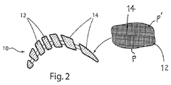
図1〜図5を参照すると、アディティブマニュファクチャリング法を用いて傾斜機能を有する鋳造用セラミックコアを作製する本発明の方法を示しており、鋳造用セラミックコア(10)は、セラミック粒子材料Pからなる内側コア本体(12)と、セラミックインベストメントシェルモールドMの中で鋳造される溶融金属又は合金との化学反応性が低減されるように前記コア本体(12)とは異なるセラミック粒子材料P’から作られたコア本体外側層(14)とを含んでいる。コア本体(12)とコア本体外側層(14)は両方とも、3Dプリンティング等のアディティブマニュファクチャリング法により、夫々のセラミック粒子(例えば、セラミック粉末)が、作製されるコア(10)の造形方向に積層して形成される。ここで、造形方向とは、アディティブマニュファクチャリング工程中に、セラミック粒子材料の層が重ねられていく方向のことである(図5の矢印Zを参照)。コア本体外側層(14)は、コア本体の上に実質的に均一な厚さを有することができるし、又は用いられる金属又は合金の厚さ変化、即ち、鋳造部品(例えば、図3を参照)の位置及び/又は鋳造用セラミックコアの位置によって長時間高温になる鋳造の時間温度条件を考慮して厚さを変化させることもできる。 Referring to FIGS. 1-5, there is shown a method of the present invention for producing a casting ceramic core having a gradient function using an additive manufacturing method, wherein the casting ceramic core (10) is made of a ceramic particle material P. The ceramic particle material P ′ different from the core body (12) so that the chemical reactivity between the inner core body (12) made of and the molten metal or alloy cast in the ceramic investment shell mold M is reduced. A core body outer layer (14) made from Both the core body (12) and the core body outer layer (14) are formed in the direction in which the core (10) is produced by the respective ceramic particles (for example, ceramic powder) by an additive manufacturing method such as 3D printing. It is formed by laminating. Here, the modeling direction is a direction in which the layers of the ceramic particle material are stacked during the additive manufacturing process (see arrow Z in FIG. 5). The core body outer layer (14) can have a substantially uniform thickness on the core body or the thickness change of the metal or alloy used, i.e. the cast part (see e.g. FIG. 3) ) And / or the position of the ceramic core for casting, the thickness can be changed in consideration of the time temperature condition of casting which becomes high temperature for a long time.
図1、2及び2Aに示された本発明の例示的実施態様において、3Dプリンティングされた鋳造用セラミックコア(10)は、例えば、冷却空気用の1又は複数の内部通路を有するベーンブレードのような中空のガスタービンエンジンエアフォイル部品の鋳造に用いられ、鋳造用セラミックコア(10)は、当該分野で広く知られているように、鋳造された超合金部品から選択的に除去されると、内部冷却空気通路を形成する。セラミックコア(10)は、鋳造部品(10)の中に所望の冷却空気通路を形成するために選択される形状を含んでいる。鋳造用セラミックコア(10)は、当該分野で広く知られているように、鋳造部品の中に複数の内壁、ペデスタル又は他の金属若しくは合金の内側構造を形成するために、細長いスロット又は開口(20)を含むことができる。例えば、スルースロット又は開口(20)には、図2Aに示されるように、溶融された超合金が鋳造中に充填され、鋳造されたエアフォイル部品Cに内壁Wが形成される。内壁は、コアが鋳造エアフォイル部品から除去されると、隣接するコア領域によって形成された冷却空気通路を分離する。このようにして、複数壁を有し、内部が冷却されるガスタービンのエアフォイル部品が生成される。
In the exemplary embodiment of the present invention shown in FIGS. 1, 2 and 2A, the 3D-printed casting
鋳造用セラミックコア(10)は、セラミックコア本体(12)と、鋳造される超合金溶湯との化学反応性が低減されるように前記コア本体(12)とは異なるセラミック材料から作られ、前記コア本体(12)の上に形成されたコア本体外側層(14)とを含んでいる。コア本体(12)とコア本体外側層(14)は両方ともアディティブマニュファクチャリング法により作製され、夫々のセラミック粒子が、作製されるコアの造形方向に積層して形成される。図2Aは、内部に焼成されたセラミックコア(10)を有するインベストメント鋳造用セラミックシェルモールドMの中で鋳造され凝固した超合金エアフォイル部品Cを示しており、これについては後で説明する。
The casting ceramic core (10) is made of a ceramic material different from the core body (12) so as to reduce chemical reactivity between the ceramic core body (12) and the molten superalloy to be cast, A core body outer layer (14) formed on the core body (12). Both the core body (12) and the core body outer layer (14) are produced by the additive manufacturing method, and the respective ceramic particles are laminated in the forming direction of the produced core. FIG. 2A shows a superalloy airfoil part C cast and solidified in an investment casting ceramic shell mold M having a fired
コア本体外側層(14)は、例えば、図4に示されるようにコア本体外側層(14)とコア本体(12)との間に配備された中間層(15)の如き副層を1又は複数層含むことができる。この副層を設けるのは、コア本体外側層からコア本体との間の焼結特性を向上させることと、コアの焼成サイクルからの冷却中又は合金鋳造工程中に、コア本体(12)とコア本体外側層(14)との熱膨張差のミスマッチに起因して外側層(14)がコア本体(12)から分離/破砕するのを防止するために前記熱膨張差を調整するためである。この目的を達成するために、中間層(15)は、コア本体外側層(14)を形成するのに用いられるセラミック粒子材料とコア本体(12)を形成するのに用いられるセラミック粒子材料との混合物から形成することができる。層間の適当な焼結性を促進し、コア本体から外側層の層分離/破砕に到る熱膨張差の発生を最小限にするために、成分が傾斜した2以上の副層を設けることもできる。 The core body outer layer (14) includes, for example, one or more sublayers such as an intermediate layer (15) disposed between the core body outer layer (14) and the core body (12) as shown in FIG. Multiple layers can be included. This sub-layer is provided to improve the sintering characteristics between the core body outer layer and the core body, and during cooling from the core firing cycle or during the alloy casting process, the core body (12) and the core This is to adjust the difference in thermal expansion in order to prevent the outer layer (14) from separating / crushing from the core body (12) due to mismatch in thermal expansion difference with the outer body layer (14). To achieve this objective, the intermediate layer (15) is composed of a ceramic particulate material used to form the core body outer layer (14) and a ceramic particulate material used to form the core body (12). It can be formed from a mixture. In order to promote appropriate sinterability between layers and minimize the occurrence of differential thermal expansion from the core body to the layer separation / crushing of the outer layer, two or more sublayers with inclined components may be provided. it can.
さらに、コア本体(12)及び/又は中間の副層(15)の多孔性を、コアの焼成サイクル後のコア本体外側層(14)よりも増大させるために、コア本体(12)及び/又は中間の副層(15)は、消失性粒子材料(図4に黒点として示されている)を含むことができる。消失性粒子材料(例えば、グラファイト粒子)(18)は、熱分解によって選択的に除去され、これによって、コア本体(12)及び/又は副層(15)の多孔性は残される。傾斜層間の適当な焼結性を促進し、層分離/破砕に到る層間の熱膨張の不均一を軽減するために、2以上の副層を設けることもできる。 Furthermore, in order to increase the porosity of the core body (12) and / or the intermediate sublayer (15) over the core body outer layer (14) after the core firing cycle, the core body (12) and / or The intermediate sublayer (15) can include a vanishing particle material (shown as black dots in FIG. 4). The vanishing particle material (eg, graphite particles) (18) is selectively removed by pyrolysis, thereby leaving the porosity of the core body (12) and / or sublayer (15). Two or more sublayers can be provided to promote appropriate sinterability between the graded layers and reduce non-uniform thermal expansion between layers leading to layer separation / crushing.
本発明はまた、セラミックコア(10)を鋳造部品から容易に除去できるようにするために、上にあるコア本体外側層(14)よりも剛性が小さくなるするための構造、多孔性及び/又は組成を有する1又は複数の副層(15)を設けることができる。例えば、中間層(15)は、セラミックコア(10)が鋳造金属又は合金部品から容易に除去できるように、より容易く破砕可能となるように作られることができる。 The present invention also provides a structure, porosity and / or porosity that is less stiff than the overlying core body outer layer (14) so that the ceramic core (10) can be easily removed from the cast part. One or more sublayers (15) having a composition can be provided. For example, the intermediate layer (15) can be made to be more easily crushed so that the ceramic core (10) can be easily removed from the cast metal or alloy part.
図3は、本発明に係る鋳造用セラミックコア(10)の他の例示的実施態様を示しており、本発明は、金属又は合金部品がコアを用いて鋳造され凝固した後、浸出剤がセラミックコア(10)の内側に容易に達することができるように、浸出剤が通るチャンネル(23a)(23b)をコア本体(12)に設けるものである。浸出剤が通るこれらのチャンネルは、コア本体(12)の位置によって異なるコア本体(12)の厚さに適合させるために、様々な形態で設けられることができる。例えば、図3において、浸出剤の主通路(23a)はコア本体の中を軸方向に延在し、浸出剤の径方向通路(23b)は、コア本体外側層(14)の厚肉部にて径方向外向きに延在している。図示の径方向通路(23b)は、主通路に沿った異なる軸方向の位置にて、主通路(23a)の周方向に、間隔をあけて設けられているが、本発明の実施に際しては他のあらゆる形態を用いることもできる。 FIG. 3 shows another exemplary embodiment of a casting ceramic core (10) according to the present invention wherein the leaching agent is ceramic after a metal or alloy part is cast and solidified using the core. The core body (12) is provided with channels (23a) and (23b) through which the leaching agent passes so that the inside of the core (10) can be easily reached. These channels through which the exudate passes can be provided in various forms to adapt to the thickness of the core body (12), which depends on the position of the core body (12). For example, in FIG. 3, the main passage (23a) of the leaching agent extends axially through the core body, and the radial passage (23b) of the leaching agent passes through the thick part of the core body outer layer (14). Extending radially outward. The illustrated radial passage (23b) is provided at intervals in the circumferential direction of the main passage (23a) at different axial positions along the main passage. Any form of can also be used.
図3において、コア本体外側層(14)は、例えばコア領域R等のように、セラミックコア(10)の異なる位置で異なる厚さを有している。例えば、図示のコア本体外側層(14)のコア領域Rでの厚さは、コア(10)に隣接する鋳造部品Cの異なる位置CRにおける金属又は合金の厚肉部に対応して変化する。さらにまた、セラミックコアの鋳造が長時間に亘って高温のより過酷な時間温度条件で行われる位置では、コア本体外側層(14)の肉厚を厚くすることもできる。コア本体外側層(14)の厚さは、例えば約0.005インチ〜0.100インチであり、この厚さは、鋳造される金属又は合金部品の肉厚変化によって生じる局部的熱負荷に依存する。 In FIG. 3, the core body outer layer (14) has different thicknesses at different positions of the ceramic core (10), such as the core region R, for example. For example, the thickness of the core body outer layer (14) shown in the figure in the core region R changes corresponding to the thick part of the metal or alloy at different positions CR of the cast part C adjacent to the core (10). Furthermore, the thickness of the core body outer layer (14) can be increased at a position where the casting of the ceramic core is performed under a severer temperature condition of a high temperature for a long time. The thickness of the core body outer layer (14) is, for example, about 0.005 inch to 0.100 inch, and this thickness depends on the local heat load caused by the thickness change of the cast metal or alloy part. To do.
セラミックコア(10)を、図5を参照して以下に説明する3Dプリンティング等のアディティブマニュファクチャリングによって作製する際、用いられるセラミック粒子材料は、典型的には粉末形態である。好ましい粒子形態は、略球状のセラミック粉末である。例示であって限定するものでないが、例えばエアフォイル部品の如きニッケル又はコバルト基超合金部品の鋳造において、コア本体外側層(14)を形成するのに希土類含有粉末(酸化物又は他の化合物)を本発明の実施に用いられることができるが、本発明の実施は、「プリント」されることができる粒子サイズの球状又は非球状粒子であればどんなセラミック粒子材料でも用いることができる。好ましい希土類酸化物はイットリアである。イットリアは、あらゆる酸化物材料の中で酸素1モル当たりのギブズ自由エネルギーが最も大きい。焼成若しくは溶融グレードの希土類酸化物(イットリア等)又は希土類酸化物含有化合物(非酸化物)のどちらでも用いられることができる。コア本体外側層(14)を形成するセラミック粉末の一般的な粒子サイズ(例えば、直径)は約1〜約75ミクロンである。セラミック粒子材料の粒子サイズは、通常、鋳造用セラミックコア(10)を形成するために堆積される追加層の厚さに応じて選択される。例えば、セラミック粒子は、主要寸法(例えば、直径)が堆積される各追加層の厚さよりも一般的に小さくなるように選択される。小さなセラミック粒子を用いることにより、小寸法で精度の良いセラミックコアが、アディティブマニュファクチャリング工程によって堆積され積層されることができる。
When the
コア本体外側層(14)は化学的反応性が小さくなるように選択されるのに対し、内側のコア本体(12)は、低コストで、容易に浸出可能なバルクコア本体セラミック粒子材料を用いて、3Dプリンティングによって形成されることができる。例示であって限定するものでないが、例えば、中空エアフォイル部品の如きニッケル又はコバルト基超合金部品の鋳造に際しては、シリカ粉末、アルミナ粉末、ジルコン粉末、ムライト粉末、及びこれら2種以上の複合粉末を3Dプリンティングすることによりコア本体(12)を形成することができる。球状コア本体粉末の粒子サイズ(直径)は典型的には約1〜約75ミクロンであるが、本発明の実施に際しては、「プリント」されることができる粒子サイズの球状又は非球状粒子であれば、適当なあらゆるセラミック粒子材料を用いて行なうことができる。前述したように、セラミック粒子材料の粒子サイズは、鋳造用セラミックコア(10)を形成するために堆積される追加層の厚さに応じて選択される。例えば、セラミック粒子の主要寸法(例えば、直径)は、堆積される各追加層の厚さよりも一般的に小さいものが選択される。小さいセラミック粒子をアディティブマニュファクチャリングすることにより、小寸法で精度の良いセラミックコアの堆積及び積層が可能となる。 The core body outer layer (14) is selected to be less chemically reactive, while the inner core body (12) is made of a low-cost, easily leachable bulk core body ceramic particulate material. It can be formed by 3D printing. For example and not limitation, for example, when casting nickel or cobalt-base superalloy parts such as hollow airfoil parts, silica powder, alumina powder, zircon powder, mullite powder, and composite powders of these two or more types The core body (12) can be formed by 3D printing. The particle size (diameter) of the spherical core body powder is typically from about 1 to about 75 microns, but in the practice of the invention, any spherical or non-spherical particle size that can be “printed”. Any suitable ceramic particulate material can be used. As described above, the particle size of the ceramic particulate material is selected according to the thickness of the additional layer deposited to form the casting ceramic core (10). For example, the major dimensions (eg, diameter) of the ceramic particles are generally selected to be smaller than the thickness of each additional layer that is deposited. By additive manufacturing of small ceramic particles, it is possible to deposit and laminate ceramic cores with small dimensions and high accuracy.
鋳造用セラミックコア(10)がアディティブマニュファクチャリング法によって形成された後、硬化性バインダー(例えば、フォトポリマーバインダー)がセラミック粉末材料と共に用いられ、アディティブマニュファクチャリング工程中に硬化していなかった場合、形成されたセラミックコア(10)は硬化プロセスに付すことができる。しかしながら、好ましくは、コア本体(12)及び外側層(14)のセラミック粒子材料は、UV硬化性(フォトポリマー)流動性バインダーとの混合物の中に堆積され、アディティブマニュファクチャリング工程中に硬化されることが好ましい。 After the casting ceramic core (10) has been formed by additive manufacturing method, a curable binder (e.g. photopolymer binder) is used with the ceramic powder material and has not been cured during the additive manufacturing process The formed ceramic core (10) can be subjected to a curing process. Preferably, however, the ceramic particulate material of the core body (12) and outer layer (14) is deposited in a mixture with a UV curable (photopolymer) flowable binder and cured during the additive manufacturing process. It is preferable.
セラミックコア(10)は、次に、焼成又は焼結ステップが行われ、コア本体(12)及びコア本体外側層(14)を作るのに用いられたセラミック粒子材料によって決められる高温及び時間の条件で加熱されて、バインダーが除去される。そして、インベストメント鋳造用シェルモールドMの中の焼成鋳造用セラミックコアの周りに溶融金属又は合金が導入される鋳造作業に耐えられるように高められたコア強度並びにその他の焼成された物理的及び化学的特性が付与される。例えば、コア本体(12)がシリカ基セラミック粉末を含み、コア外側層(14)が前述したイットリアを含むセラミックコアを用いてニッケル又はコバルト基超合金の鋳造を行なう場合、適当なコア強度並びにその他の焼成された物理的及び化学的特性を確保するための焼結温度は2000〜2800°F、加熱時間は約80時間以下である。 The ceramic core (10) is then subjected to a firing or sintering step, with high temperature and time conditions determined by the ceramic particulate material used to make the core body (12) and core body outer layer (14). And the binder is removed. And increased core strength and other fired physical and chemical strength to withstand casting operations in which molten metal or alloy is introduced around the fired casting ceramic core in investment casting shell mold M. Properties are added. For example, when casting a nickel or cobalt base superalloy using a ceramic core in which the core body (12) includes silica-based ceramic powder and the core outer layer (14) includes yttria as described above, suitable core strength and other The sintering temperature for securing the calcined physical and chemical properties is 2000-2800 ° F., and the heating time is about 80 hours or less.
例示であって限定するものではないが、図2Aは、鋳造エアフォイル超合金部品Cの断面を示しており、前記部品Cは、セラミック鋳造用シェルモールドMの中にあり、焼成された鋳造用セラミックコア(10)は前記モールドの中にある。エアフォイル超合金部品Cが鋳造され凝固した後、インベストメント鋳造シェルモールドM及び焼成された鋳造用セラミックコア(10)は、当業者に広く知られている方法で除去される。これは、本発明の一部を構成しない。
By way of example and not limitation, FIG. 2A shows a cross-section of a cast airfoil superalloy part C, which is in a ceramic casting shell mold M and fired for casting. The ceramic core (10) is in the mold. After the airfoil superalloy part C is cast and solidified, the investment casting shell mold M and the fired casting
前述した鋳造用セラミックコア(10)は、デザイン電子モデル等のセラミックコアのモデルを用いて、あらゆる適当なアディティブマニュファクチャリングプロセスにより、あらゆる適当な方法に基づいて形成されることができる。アディティブマニュファクチャリング法では、異なるセラミック粒子材料の層を堆積することにより、コア本体(12)及びコア本体外側層(14)を形成することができる。部品のモデルは、コンピュータ支援設計(CAD)ソフトウエアを用いて設計されることができる。モデルは、外表面及び内表面の両表面を含む部品の全体構成である3D数値座標を含んでいる。モデルは、3D部品を形成する複数の二次元スライスを含むこともできる。 The above-described casting ceramic core (10) can be formed in any suitable manner by any suitable additive manufacturing process using a ceramic core model such as a design electronic model. In the additive manufacturing method, the core body (12) and the core body outer layer (14) can be formed by depositing layers of different ceramic particulate materials. The part model can be designed using computer aided design (CAD) software. The model includes 3D numerical coordinates that are the overall configuration of the part including both the outer and inner surfaces. The model can also include a plurality of two-dimensional slices that form a 3D part.
図5は、本発明を実施するのに用いられる望ましいアディティブマニュファクチャリング法の例として、直接書込み(3Dプリンティング)を示しており、異なるセラミック粒子の層が支持体又はトレイ(50)の上に堆積され、低コストで、容易に浸出可能なセラミック粒子材料を含むコア本体(12)と、略非反応性のセラミックバリア層(14)を含むコア本体外側層(14)とが形成される。コア本体(12)及びコア本体外側層(14)のセラミック粒子材料は、アディティブマニュファクチャリング工程中に硬化する、低密度で低表面張力のUV硬化性(フォトポリマー)流動性バインダーと混合された状態で堆積される。セラミック粉末と硬化性バインダーとの混合は様々な混合技術を用いて行なうことができる。その混合技術として、限定するものではないが、例えばプラネタリー混合(例えば、Charles Ross & Son, Hauppauge, NY 製造によるDPMミキサー)により、3Dプリントが可能な流動性組成物が得られる。例えば、この直接書込み工程では、複数のノズル(例えば、2以上のノズル)を有するカセット(52)が配備される。鋳造用セラミックコア(10)を作製するために、ノズル(54)の1つはコントローラ(62)を通じてコンピュータ制御され、高浸出性及び低コストのセラミック粒子材料と低粘度及び低表面張力のUV硬化性バインダーとの混合物が、コア本体(12)の所望される2D形状の層として堆積(スプレー)される。また、他方のノズルは、コントローラ(62)を通じてコンピュータ制御されており、カセット(52)がキャリッジ(60)(一部が図示されている)上を、スタート位置(例えば、トレイ(50)の左側の位置)から最終位置(例えば、トレイ(50)の右側の位置)へ横方向移動すると、実質的に非反応性のセラミック粒子材料(例えば、イットリア粉末)と低粘度及び低表面張力のUV硬化性バインダーとの混合物が、コア本体外側層(14)の所望される2D形状の層として堆積される。セラミック粉末とUV硬化性バインダーとの混合物は、カセット(52)上のコンパートメントS1、S2から供給されることができるし、或いは外部混合物貯蔵タンクから供給導管を通じて直接供給されることもできる。図5において、トレイ(50)上に示された堆積されたばかりの粉末/バインダー層は、カセット(52)が横方向に移動してスタート位置に戻ると、キャリッジ(60)に配備されたUVランプLによって硬化される。UVランプの具体的波長は、用いられるUV硬化性バインダーに基づいて選択される。トレイ(50)は所定寸法ずつ垂直造形方向Zに下降できるようになっており、トレイ(50)を所定寸法下降させて、コア本体及び外側層の堆積/硬化されたばかりの粉末/バインダー層の上面に、次の粉末/バインダー層が堆積される。このように層の上に層を重ねるプロセスが繰り返され、トレイ(50)の上に前述した鋳造用セラミックコアが形成される。直接書込みプリンティング法は、例えば、Pro-Jet(登録商標) Model 5500X プリンター(3D Systems, Rock Hill, South Carolina)又はStratasys model Connex 350プリンター(Stratasys, Ltd, Eden Prairie, Minnesota)等の直接書込3Dプリンターを用いて行なうことができるが、これらは例示であって、限定するものではない。Pro-Jet Model 5500X プリンターに適したUV硬化性フォトポリマーバインダーとして、3D Systemsが販売しているVisiJet CR-CL、VisiJet CR-WT及びVisiJet CF-BKを挙げることができるが、これらに限定されない。Stratasys model Connex 350プリンターに適したUV硬化性フォトポリマーバインダーとして、Stratasys, Ltdが販売しているRGD450及びRGD525を挙げることができるが、これらに限定されない。 FIG. 5 shows direct writing (3D printing) as an example of a desirable additive manufacturing method used to implement the present invention, where different layers of ceramic particles are placed on a support or tray (50). A core body (12) comprising a deposited, low-cost, easily leachable ceramic particulate material and a core body outer layer (14) comprising a substantially non-reactive ceramic barrier layer (14) are formed. The ceramic particle material of the core body (12) and core body outer layer (14) was mixed with a low density, low surface tension UV curable (photopolymer) flowable binder that hardens during the additive manufacturing process. Deposited in a state. The mixing of the ceramic powder and the curable binder can be performed using various mixing techniques. The mixing technique includes, but is not limited to, a flowable composition capable of 3D printing, for example, by planetary mixing (eg, DPM mixer manufactured by Charles Ross & Son, Hauppauge, NY). For example, in the direct writing process, a cassette (52) having a plurality of nozzles (for example, two or more nozzles) is provided. To make the casting ceramic core (10), one of the nozzles (54) is computer controlled through the controller (62) to provide high leachability and low cost ceramic particulate material and low viscosity and low surface tension UV curing. The mixture with the functional binder is deposited (sprayed) as a desired 2D shaped layer of the core body (12). The other nozzle is computer-controlled through the controller (62), and the cassette (52) moves over the carriage (60) (partially shown) to the start position (for example, to the left of the tray (50)). Position) to the final position (e.g., the position to the right of the tray (50)) and substantially non-reactive ceramic particulate material (e.g., yttria powder) and low viscosity and low surface tension UV curing. The mixture with the functional binder is deposited as a desired 2D shaped layer of the core body outer layer (14). The mixture of ceramic powder and UV curable binder can be supplied from the compartments S1, S2 on the cassette (52) or directly from an external mixture storage tank through a supply conduit. In FIG. 5, the freshly deposited powder / binder layer shown on the tray (50) is a UV lamp deployed in the carriage (60) when the cassette (52) moves laterally and returns to the start position. Cured by L. The specific wavelength of the UV lamp is selected based on the UV curable binder used. The tray (50) can be lowered in the vertical forming direction Z by a predetermined dimension, and the upper surface of the powder / binder layer just deposited / cured on the core body and the outer layer by lowering the tray (50) by a predetermined dimension. The next powder / binder layer is deposited. Thus, the process of stacking the layers on the layers is repeated, and the above-described casting ceramic core is formed on the tray (50). The direct write printing method is, for example, a direct write 3D such as a Pro-Jet® Model 5500X printer (3D Systems, Rock Hill, South Carolina) or a Stratasys model Connex 350 printer (Stratasys, Ltd, Eden Prairie, Minnesota). Although it can be performed using a printer, these are examples and are not limited. Suitable UV curable photopolymer binders for Pro-Jet Model 5500X printers include, but are not limited to, VisiJet CR-CL, VisiJet CR-WT and VisiJet CF-BK sold by 3D Systems. UV curable photopolymer binders suitable for Stratasys model Connex 350 printers include, but are not limited to, RGD450 and RGD525 sold by Stratasys, Ltd.
本発明は、アディティブマニュファクチャリング技術を用いることに利点があり、セラミック粒子材料からコア本体外側層をバルクコア本体から独立して正確に形成することができる。例えば、コア本体外側層は、バルクコア本体の化学的性質及び/又は粒子サイズに対して選択的に非反応性であるセラミック粒子状材料から構成されることができる。コア本体外側層及び内側コア本体について得られる多孔性は、消失性粒子材料をセラミック粒子材料に加えることにより、独立して決定され制御されることができる。非反応性のコア本体外側層は、用いる合金の厚さ又は時間温度鋳造条件の変動に対応して、特定の単一セラミックコアの設計範囲内で様々な厚さに作られることができるし、また、セラミックコアの形状に対応する厚さに作られることもできる。さらに、アディティブマニュファクチャリングは、セラミックコアの内部で浸出性の少ない周囲層の厚肉領域に隣接する位置に浸出性を向上させるためのチャンネル又は空間を設けることができる。 The present invention has the advantage of using additive manufacturing techniques, and the core body outer layer can be accurately formed independently of the bulk core body from ceramic particulate material. For example, the core body outer layer can be composed of a ceramic particulate material that is selectively non-reactive with the bulk core body chemistry and / or particle size. The porosity obtained for the core body outer layer and the inner core body can be independently determined and controlled by adding the vanishing particle material to the ceramic particle material. The non-reactive core body outer layer can be made to various thicknesses within the design range of a particular single ceramic core, corresponding to variations in the alloy thickness or time temperature casting conditions used, It can also be made to a thickness corresponding to the shape of the ceramic core. Furthermore, additive manufacturing can provide a channel or space for improving leachability at a position adjacent to the thick region of the surrounding layer having less leachability within the ceramic core.
本発明はまた、アディティブマニュファクチャリングを、セラミックコアに非反応性の外部層を設けることによって反応が最小限に抑えられるか又は全く起こることなく金属又は合金の鋳造部品を作ることができる手段として提供することに利点がある。この層は、鋳造工程中に最も反応を受け易いセラミックコアの周囲領域の正確な位置に必要な厚さに作られさえすればよく、鋳造エアフォイル部品等の鋳造ガスタービンエンジン部品又は他のあらゆる鋳造部品を、少ない反応で又は反応が全く起こることなく製造することができる。 The present invention also provides additive manufacturing as a means by which a non-reactive outer layer on the ceramic core can be used to make a cast part of a metal or alloy with minimal or no reaction. There are advantages to providing. This layer need only be made to the required thickness at the exact location in the surrounding area of the ceramic core that is most susceptible to reaction during the casting process, and can be any cast gas turbine engine component such as a cast airfoil component or any other Cast parts can be produced with little or no reaction.
本発明について、特定の実施形態に基づいて説明したが、当業者であれば、特許請求の範囲に記載された発明の範囲内で変形及び改変を行なうことができることは認識されるであろう。 Although the invention has been described with reference to particular embodiments, those skilled in the art will recognize that variations and modifications can be made within the scope of the claimed invention.
Claims (28)
Applications Claiming Priority (2)
| Application Number | Priority Date | Filing Date | Title |
|---|---|---|---|
| US201461995901P | 2014-04-24 | 2014-04-24 | |
| US61/995901 | 2014-04-24 |
Publications (2)
| Publication Number | Publication Date |
|---|---|
| JP2015226935A true JP2015226935A (en) | 2015-12-17 |
| JP2015226935A5 JP2015226935A5 (en) | 2019-01-17 |
Family
ID=52946425
Family Applications (1)
| Application Number | Title | Priority Date | Filing Date |
|---|---|---|---|
| JP2015084080A Pending JP2015226935A (en) | 2014-04-24 | 2015-04-16 | Ceramic casting core made by additive manufacturing |
Country Status (5)
| Country | Link |
|---|---|
| US (1) | US20150306657A1 (en) |
| EP (1) | EP2937161A1 (en) |
| JP (1) | JP2015226935A (en) |
| CA (1) | CA2885074A1 (en) |
| HK (1) | HK1210094A1 (en) |
Cited By (8)
| Publication number | Priority date | Publication date | Assignee | Title |
|---|---|---|---|---|
| JP2017094397A (en) * | 2015-11-19 | 2017-06-01 | ゼネラル・エレクトリック・カンパニイ | Compositions for cores used in investment casting |
| KR101827265B1 (en) * | 2016-08-03 | 2018-02-09 | 한국세라믹기술원 | Dual ceramic mold using 3d printing and method for manufacturing metal product using the same |
| DE102017119319A1 (en) | 2016-08-24 | 2018-03-01 | Noritake Co., Limited | LAYERED BUILT-BURNED BODY, METHOD FOR PRODUCING A LAYERED BURNTED BODY, AND KIT FOR PRODUCING A LAYERED BURNTIED BODY |
| KR20180066295A (en) * | 2016-12-07 | 2018-06-19 | 한국세라믹기술원 | Dual ceramic mold and method for manufacturing metal product having nanopores |
| KR20180100493A (en) * | 2017-03-01 | 2018-09-11 | 에스에이에스 쓰리디세람-신토 | Method for manufacturing pieces by the technique of additive manufacturing by pasty process with an improved supply of paste and manufacturing machine for implementing the method |
| KR20190041567A (en) * | 2017-10-13 | 2019-04-23 | 엠에이치기술개발 주식회사 | Ring-shaped structure for enhancing strength of pipe used in die casting and method using the same |
| KR20190063918A (en) | 2017-11-30 | 2019-06-10 | 서울대학교산학협력단 | Manufacturing method of multi-scale porous three-dimensional suspended structures using super or sub critical fluid and three-dimensional suspended structures thereof |
| CN112500143A (en) * | 2020-11-25 | 2021-03-16 | 西安国宏中天增材技术有限公司 | Silicon-based ceramic core slurry and application thereof |
Families Citing this family (45)
| Publication number | Priority date | Publication date | Assignee | Title |
|---|---|---|---|---|
| WO2015112885A1 (en) * | 2014-01-23 | 2015-07-30 | United Technologies Corporation | An additive manufactured mold, a method of manufacturing the mold, and a workpiece casted from the mold |
| US10137499B2 (en) * | 2015-12-17 | 2018-11-27 | General Electric Company | Method and assembly for forming components having an internal passage defined therein |
| US9968991B2 (en) | 2015-12-17 | 2018-05-15 | General Electric Company | Method and assembly for forming components having internal passages using a lattice structure |
| US10150158B2 (en) | 2015-12-17 | 2018-12-11 | General Electric Company | Method and assembly for forming components having internal passages using a jacketed core |
| US10046389B2 (en) | 2015-12-17 | 2018-08-14 | General Electric Company | Method and assembly for forming components having internal passages using a jacketed core |
| US9987677B2 (en) | 2015-12-17 | 2018-06-05 | General Electric Company | Method and assembly for forming components having internal passages using a jacketed core |
| US10118217B2 (en) | 2015-12-17 | 2018-11-06 | General Electric Company | Method and assembly for forming components having internal passages using a jacketed core |
| US10099284B2 (en) | 2015-12-17 | 2018-10-16 | General Electric Company | Method and assembly for forming components having a catalyzed internal passage defined therein |
| US10099276B2 (en) * | 2015-12-17 | 2018-10-16 | General Electric Company | Method and assembly for forming components having an internal passage defined therein |
| US10099283B2 (en) | 2015-12-17 | 2018-10-16 | General Electric Company | Method and assembly for forming components having an internal passage defined therein |
| US9579714B1 (en) | 2015-12-17 | 2017-02-28 | General Electric Company | Method and assembly for forming components having internal passages using a lattice structure |
| US10226812B2 (en) * | 2015-12-21 | 2019-03-12 | United Technologies Corporation | Additively manufactured core for use in casting an internal cooling circuit of a gas turbine engine component |
| US20170246679A1 (en) * | 2016-02-29 | 2017-08-31 | General Electric Company | Casting with graded core components |
| US20170246678A1 (en) * | 2016-02-29 | 2017-08-31 | General Electric Company | Casting with first metal components and second metal components |
| CN105665620B (en) * | 2016-04-08 | 2018-03-16 | 宁夏共享模具有限公司 | A kind of preparation method of the water base Flow Coating of 3D printing sand mold |
| US10286450B2 (en) | 2016-04-27 | 2019-05-14 | General Electric Company | Method and assembly for forming components using a jacketed core |
| US10335853B2 (en) | 2016-04-27 | 2019-07-02 | General Electric Company | Method and assembly for forming components using a jacketed core |
| US10344599B2 (en) * | 2016-05-24 | 2019-07-09 | General Electric Company | Cooling passage for gas turbine rotor blade |
| US10179362B2 (en) | 2016-07-20 | 2019-01-15 | United Technologies Corporation | System and process to provide self-supporting additive manufactured ceramic core |
| US10279388B2 (en) | 2016-08-03 | 2019-05-07 | General Electric Company | Methods for forming components using a jacketed mold pattern |
| US11813669B2 (en) | 2016-12-13 | 2023-11-14 | General Electric Company | Method for making an integrated core-shell structure |
| US20180161866A1 (en) | 2016-12-13 | 2018-06-14 | General Electric Company | Multi-piece integrated core-shell structure for making cast component |
| US10022794B1 (en) | 2017-01-13 | 2018-07-17 | General Electric Company | Additive manufacturing using a mobile build volume |
| US10478893B1 (en) | 2017-01-13 | 2019-11-19 | General Electric Company | Additive manufacturing using a selective recoater |
| US11154956B2 (en) | 2017-02-22 | 2021-10-26 | General Electric Company | Method of repairing turbine component using ultra-thin plate |
| US10702958B2 (en) | 2017-02-22 | 2020-07-07 | General Electric Company | Method of manufacturing turbine airfoil and tip component thereof using ceramic core with witness feature |
| US10610933B2 (en) * | 2017-02-22 | 2020-04-07 | General Electric Company | Method of manufacturing turbine airfoil with open tip casting and tip component thereof |
| US10717130B2 (en) | 2017-02-22 | 2020-07-21 | General Electric Company | Method of manufacturing turbine airfoil and tip component thereof |
| CN107127306B (en) * | 2017-06-07 | 2024-01-19 | 第一拖拉机股份有限公司 | Device for 3D printing precision casting mold shell and use method |
| US10391549B2 (en) | 2017-06-28 | 2019-08-27 | General Electric Company | Additively manufactured casting core-shell hybrid mold and ceramic shell |
| US11173542B2 (en) * | 2017-06-28 | 2021-11-16 | General Electric Company | Additively manufactured casting core-shell mold and ceramic shell with variable thermal properties |
| US10974312B2 (en) | 2017-06-28 | 2021-04-13 | General Electric Company | Additively manufactured casting core-shell mold with integrated filter and ceramic shell |
| US11192172B2 (en) * | 2017-06-28 | 2021-12-07 | General Electric Company | Additively manufactured interlocking casting core structure with ceramic shell |
| US10391670B2 (en) * | 2017-06-28 | 2019-08-27 | General Electric Company | Additively manufactured integrated casting core structure with ceramic shell |
| US11033955B2 (en) | 2017-10-03 | 2021-06-15 | Raytheon Technologies Corporation | Printing-enhanced casting cores |
| US10538460B2 (en) | 2018-03-15 | 2020-01-21 | General Electric Company | Ceramic slurries for additive manufacturing techniques |
| CN108543935B (en) * | 2018-04-12 | 2020-09-18 | 北京科技大学 | Method for preparing metal-based SHS (super thin-layer high-resolution) wear-resistant coating by combining 3D (three-dimensional) printing with vacuum lost foam |
| US11198640B2 (en) * | 2018-06-10 | 2021-12-14 | Dylan Kelley | Systems, devices, and/or methods for images |
| DE102018215957A1 (en) * | 2018-09-19 | 2020-03-19 | Fraunhofer-Gesellschaft zur Förderung der angewandten Forschung e.V. | Casting core for casting molds and process for its production |
| DE102018215962A1 (en) * | 2018-09-19 | 2020-03-19 | Fraunhofer-Gesellschaft zur Förderung der angewandten Forschung e.V. | Casting core for casting molds and process for its production |
| CN110734278A (en) * | 2019-10-22 | 2020-01-31 | 康硕(德阳)智能制造有限公司 | Hollow blade ceramic core material, preparation method thereof and method for manufacturing hollow blade ceramic core by using material |
| WO2021086373A1 (en) * | 2019-10-31 | 2021-05-06 | Siemens Energy Global GmbH & Co. KG | Effective leaching of alumina-based casting cores |
| CN112250473B (en) * | 2020-10-20 | 2022-06-14 | 西安工程大学 | Gradient porous ceramic core and preparation method thereof |
| CN116102364B (en) * | 2022-12-29 | 2024-04-05 | 江苏华钛瑞翔科技有限公司 | Anti-cracking inert ceramic core and preparation method thereof |
| CN116444272A (en) * | 2023-03-13 | 2023-07-18 | 成都先进金属材料产业技术研究院股份有限公司 | Preparation method of rotating disc, rotating disc and application of rotating disc |
Citations (8)
| Publication number | Priority date | Publication date | Assignee | Title |
|---|---|---|---|---|
| JPS62143864A (en) * | 1985-06-06 | 1987-06-27 | レメツト コ−ポレ−シヨン | Refractory composition |
| JPH08509666A (en) * | 1994-05-27 | 1996-10-15 | イーオーエス ゲゼルシャフト ミット ベシュレンクテル ハフツング イレクトロ オプティカル システムズ | Method used in casting technology |
| JPH08276241A (en) * | 1986-07-11 | 1996-10-22 | Howmet Corp | Reactive metal casting |
| JP2004330280A (en) * | 2003-05-12 | 2004-11-25 | Ishikawajima Harima Heavy Ind Co Ltd | Heat-resistant ceramic core having three-dimensional shape and method for producing cast product using this core |
| JP2005144870A (en) * | 2003-11-14 | 2005-06-09 | Noritake Co Ltd | Method and apparatus for manufacturing three-dimensional molding |
| JP2006123006A (en) * | 2004-10-26 | 2006-05-18 | United Technol Corp <Utc> | Investment casting core having non-oxidizable coating |
| JP2013071169A (en) * | 2011-09-29 | 2013-04-22 | Hitachi Ltd | Ceramic core for precision casting, and method for manufacturing the same |
| JP2013215805A (en) * | 2012-04-09 | 2013-10-24 | General Electric Co <Ge> | Composite core for casting process, and process of making and using the same |
Family Cites Families (9)
| Publication number | Priority date | Publication date | Assignee | Title |
|---|---|---|---|---|
| US4191720A (en) * | 1977-10-06 | 1980-03-04 | General Electric Company | Method for making porous, crushable core having an integral outer barrier layer |
| US5690759A (en) * | 1996-06-24 | 1997-11-25 | General Motors Corporation | Coated permanent mold having textured undersurface |
| DE19948591A1 (en) * | 1999-10-08 | 2001-04-19 | Generis Gmbh | Rapid prototyping method and device |
| US7575042B2 (en) * | 2006-03-30 | 2009-08-18 | General Electric Company | Methods for the formation of refractory metal intermetallic composites, and related articles and compositions |
| US8393381B2 (en) * | 2011-05-18 | 2013-03-12 | Pcc Airfoils, Inc. | Method of forming a cast metal article |
| US9551228B2 (en) * | 2013-01-09 | 2017-01-24 | United Technologies Corporation | Airfoil and method of making |
| US10525525B2 (en) * | 2013-07-19 | 2020-01-07 | United Technologies Corporation | Additively manufactured core |
| WO2015112885A1 (en) * | 2014-01-23 | 2015-07-30 | United Technologies Corporation | An additive manufactured mold, a method of manufacturing the mold, and a workpiece casted from the mold |
| CN104028713B (en) * | 2014-05-28 | 2016-03-30 | 宁夏共享模具有限公司 | A kind of multi-functional pair of printhead 3D printing device based on 3DP technique |
-
2015
- 2015-03-12 CA CA2885074A patent/CA2885074A1/en not_active Abandoned
- 2015-04-16 US US14/545,283 patent/US20150306657A1/en not_active Abandoned
- 2015-04-16 JP JP2015084080A patent/JP2015226935A/en active Pending
- 2015-04-17 EP EP15163992.9A patent/EP2937161A1/en not_active Withdrawn
- 2015-11-06 HK HK15110976.0A patent/HK1210094A1/en unknown
Patent Citations (8)
| Publication number | Priority date | Publication date | Assignee | Title |
|---|---|---|---|---|
| JPS62143864A (en) * | 1985-06-06 | 1987-06-27 | レメツト コ−ポレ−シヨン | Refractory composition |
| JPH08276241A (en) * | 1986-07-11 | 1996-10-22 | Howmet Corp | Reactive metal casting |
| JPH08509666A (en) * | 1994-05-27 | 1996-10-15 | イーオーエス ゲゼルシャフト ミット ベシュレンクテル ハフツング イレクトロ オプティカル システムズ | Method used in casting technology |
| JP2004330280A (en) * | 2003-05-12 | 2004-11-25 | Ishikawajima Harima Heavy Ind Co Ltd | Heat-resistant ceramic core having three-dimensional shape and method for producing cast product using this core |
| JP2005144870A (en) * | 2003-11-14 | 2005-06-09 | Noritake Co Ltd | Method and apparatus for manufacturing three-dimensional molding |
| JP2006123006A (en) * | 2004-10-26 | 2006-05-18 | United Technol Corp <Utc> | Investment casting core having non-oxidizable coating |
| JP2013071169A (en) * | 2011-09-29 | 2013-04-22 | Hitachi Ltd | Ceramic core for precision casting, and method for manufacturing the same |
| JP2013215805A (en) * | 2012-04-09 | 2013-10-24 | General Electric Co <Ge> | Composite core for casting process, and process of making and using the same |
Cited By (13)
| Publication number | Priority date | Publication date | Assignee | Title |
|---|---|---|---|---|
| JP2017094397A (en) * | 2015-11-19 | 2017-06-01 | ゼネラル・エレクトリック・カンパニイ | Compositions for cores used in investment casting |
| KR101827265B1 (en) * | 2016-08-03 | 2018-02-09 | 한국세라믹기술원 | Dual ceramic mold using 3d printing and method for manufacturing metal product using the same |
| DE102017119319A1 (en) | 2016-08-24 | 2018-03-01 | Noritake Co., Limited | LAYERED BUILT-BURNED BODY, METHOD FOR PRODUCING A LAYERED BURNTED BODY, AND KIT FOR PRODUCING A LAYERED BURNTIED BODY |
| KR20180066295A (en) * | 2016-12-07 | 2018-06-19 | 한국세라믹기술원 | Dual ceramic mold and method for manufacturing metal product having nanopores |
| KR101907888B1 (en) * | 2016-12-07 | 2018-10-16 | 한국세라믹기술원 | Metal product having nanopores and method for manufacturing the same |
| JP2018144486A (en) * | 2017-03-01 | 2018-09-20 | トゥロワデセラム | Method for producing piece with additive manufacturing technology by processing of paste with improved supply of paste and production machine for conducting said method |
| CN108527603A (en) * | 2017-03-01 | 2018-09-14 | 三维陶瓷公司 | Method and machine for manufacturing blank by increases material manufacturing technology |
| KR20180100493A (en) * | 2017-03-01 | 2018-09-11 | 에스에이에스 쓰리디세람-신토 | Method for manufacturing pieces by the technique of additive manufacturing by pasty process with an improved supply of paste and manufacturing machine for implementing the method |
| KR102039061B1 (en) * | 2017-03-01 | 2019-10-31 | 에스에이에스 쓰리디세람-신토 | Method for manufacturing pieces by the technique of additive manufacturing by pasty process with an improved supply of paste and manufacturing machine for implementing the method |
| KR20190041567A (en) * | 2017-10-13 | 2019-04-23 | 엠에이치기술개발 주식회사 | Ring-shaped structure for enhancing strength of pipe used in die casting and method using the same |
| KR101984802B1 (en) * | 2017-10-13 | 2019-06-03 | 엠에이치기술개발 주식회사 | Ring-shaped structure for enhancing strength of pipe used in die casting |
| KR20190063918A (en) | 2017-11-30 | 2019-06-10 | 서울대학교산학협력단 | Manufacturing method of multi-scale porous three-dimensional suspended structures using super or sub critical fluid and three-dimensional suspended structures thereof |
| CN112500143A (en) * | 2020-11-25 | 2021-03-16 | 西安国宏中天增材技术有限公司 | Silicon-based ceramic core slurry and application thereof |
Also Published As
| Publication number | Publication date |
|---|---|
| US20150306657A1 (en) | 2015-10-29 |
| HK1210094A1 (en) | 2016-04-15 |
| EP2937161A1 (en) | 2015-10-28 |
| CA2885074A1 (en) | 2015-10-24 |
Similar Documents
| Publication | Publication Date | Title |
|---|---|---|
| JP2015226935A (en) | Ceramic casting core made by additive manufacturing | |
| EP2986760B1 (en) | Regenerating an additively manufactured component to cure defects and alter microstructure | |
| US9079803B2 (en) | Additive manufacturing hybrid core | |
| EP1930098B1 (en) | Ceramic cores, methods of manufacture thereof and articles manufactured from the same | |
| EP1534451B1 (en) | Casting process | |
| US9901977B2 (en) | Patternless sand mold and core formation for rapid casting | |
| US20050156361A1 (en) | Methods for producing complex ceramic articles | |
| JP6937587B2 (en) | Casting method including step-by-step core parts | |
| EP3281730B1 (en) | System and method for forming directionally solidified part from additively manufactured article | |
| US20220098119A1 (en) | Resin for production of porous ceramic stereolithography and methods of its use | |
| US20220126365A1 (en) | System and method for forming part from rapidly manufactured article |
Legal Events
| Date | Code | Title | Description |
|---|---|---|---|
| A621 | Written request for application examination |
Free format text: JAPANESE INTERMEDIATE CODE: A621 Effective date: 20180222 |
|
| A521 | Request for written amendment filed |
Free format text: JAPANESE INTERMEDIATE CODE: A523 Effective date: 20181203 |
|
| A977 | Report on retrieval |
Free format text: JAPANESE INTERMEDIATE CODE: A971007 Effective date: 20181225 |
|
| A131 | Notification of reasons for refusal |
Free format text: JAPANESE INTERMEDIATE CODE: A131 Effective date: 20190205 |
|
| A02 | Decision of refusal |
Free format text: JAPANESE INTERMEDIATE CODE: A02 Effective date: 20190910 |