JP2015201729A - Mixer circuit, audio signal processing circuit, audio signal mixing method, on-vehicle audio device using the method, audio component device, and electronic apparatus - Google Patents
Mixer circuit, audio signal processing circuit, audio signal mixing method, on-vehicle audio device using the method, audio component device, and electronic apparatus Download PDFInfo
- Publication number
- JP2015201729A JP2015201729A JP2014078825A JP2014078825A JP2015201729A JP 2015201729 A JP2015201729 A JP 2015201729A JP 2014078825 A JP2014078825 A JP 2014078825A JP 2014078825 A JP2014078825 A JP 2014078825A JP 2015201729 A JP2015201729 A JP 2015201729A
- Authority
- JP
- Japan
- Prior art keywords
- audio signal
- analog audio
- analog
- digital
- circuit
- Prior art date
- Legal status (The legal status is an assumption and is not a legal conclusion. Google has not performed a legal analysis and makes no representation as to the accuracy of the status listed.)
- Pending
Links
Images


Classifications
-
- H—ELECTRICITY
- H04—ELECTRIC COMMUNICATION TECHNIQUE
- H04R—LOUDSPEAKERS, MICROPHONES, GRAMOPHONE PICK-UPS OR LIKE ACOUSTIC ELECTROMECHANICAL TRANSDUCERS; DEAF-AID SETS; PUBLIC ADDRESS SYSTEMS
- H04R3/00—Circuits for transducers, loudspeakers or microphones
-
- H—ELECTRICITY
- H04—ELECTRIC COMMUNICATION TECHNIQUE
- H04R—LOUDSPEAKERS, MICROPHONES, GRAMOPHONE PICK-UPS OR LIKE ACOUSTIC ELECTROMECHANICAL TRANSDUCERS; DEAF-AID SETS; PUBLIC ADDRESS SYSTEMS
- H04R2420/00—Details of connection covered by H04R, not provided for in its groups
- H04R2420/01—Input selection or mixing for amplifiers or loudspeakers
-
- H—ELECTRICITY
- H04—ELECTRIC COMMUNICATION TECHNIQUE
- H04R—LOUDSPEAKERS, MICROPHONES, GRAMOPHONE PICK-UPS OR LIKE ACOUSTIC ELECTROMECHANICAL TRANSDUCERS; DEAF-AID SETS; PUBLIC ADDRESS SYSTEMS
- H04R2499/00—Aspects covered by H04R or H04S not otherwise provided for in their subgroups
- H04R2499/10—General applications
- H04R2499/13—Acoustic transducers and sound field adaptation in vehicles
-
- H—ELECTRICITY
- H04—ELECTRIC COMMUNICATION TECHNIQUE
- H04R—LOUDSPEAKERS, MICROPHONES, GRAMOPHONE PICK-UPS OR LIKE ACOUSTIC ELECTROMECHANICAL TRANSDUCERS; DEAF-AID SETS; PUBLIC ADDRESS SYSTEMS
- H04R5/00—Stereophonic arrangements
- H04R5/04—Circuit arrangements, e.g. for selective connection of amplifier inputs/outputs to loudspeakers, for loudspeaker detection, or for adaptation of settings to personal preferences or hearing impairments
Landscapes
- Physics & Mathematics (AREA)
- Engineering & Computer Science (AREA)
- Acoustics & Sound (AREA)
- Signal Processing (AREA)
- Amplifiers (AREA)
Abstract
Description
本発明は、2つのオーディオ信号をミキシングするミキサー回路に関する。 The present invention relates to a mixer circuit that mixes two audio signals.
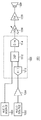
CDプレイヤ、オーディオアンプ、カーステレオあるいは携帯型ラジオや携帯型のオーディオプレイヤに例示されるように、オーディオ信号を再生する機能を備えたオーディオシステムが広く普及している。図1は、一般的なオーディオシステムの構成を示すブロック図である。 As exemplified by CD players, audio amplifiers, car stereos, portable radios, and portable audio players, audio systems having a function of reproducing audio signals are widely used. FIG. 1 is a block diagram showing a configuration of a general audio system.
オーディオシステム1001は、音源1002、1003、アナログアンプ1004、A/Dコンバータ1010、DSP(Digital Signal ProcessorあるいはDigital Sound Processor)1012、D/Aコンバータ1014、アナログアンプ1006、パワーアンプ1008、電気音響変換素子1009を備える。
The
アナログ音源1002は、CDプレイヤ、シリコンオーディオプレイヤ、携帯電話端末などであり、アナログオーディオ信号を出力する。アナログアンプ1004は、アナログ音源1002からのアナログオーディオ信号を増幅し、後段のA/Dコンバータ1010の入力レンジにマッチさせる。またデジタル音源1003はCDプレイヤ、シリコンオーディオプレイヤ、携帯電話端末であり、デジタル形式のオーディオ信号を出力する。DSP1012は、前段のA/Dコンバータ1010からのデジタルオーディオ信号、またはデジタル音源1003からのデジタルオーディオ信号を受け、所定のデジタル信号処理を施す。DSP1012による信号処理としては、イコライジング、バスブースト、トレブルブースト、ステレオ−モノラル変換、デジタルボリウム制御などが例示される。
The
D/Aコンバータ1014は、DSP1012による処理を受けたデジタルオーディオ信号をアナログオーディオ信号に変換する。アナログアンプ1006はたとえばアナログボリウム回路であり、D/Aコンバータ1014の出力信号をボリウム値に応じた利得で増幅する。パワーアンプ1008は、アナログアンプ1006の出力を増幅し、電気音響変換素子1009であるスピーカやヘッドホンを駆動する。
The D /
こうしたオーディオシステム1001において、異なる複数の音源1002、1003からのオーディオ信号をミキシングして再生する場合がある。たとえば車載用オーディオシステムでは、メインとなる音源(たとえばCDプレイヤやテレビ)からのオーディオ信号を再生中に、カーナビの案内音声をミキシングして再生する場合がある。
In such an
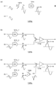
図2(a)〜(c)は、本発明者が検討したミキサー回路のブロック図である。
図2(a)のミキサー回路1200aは、デジタル加算器1202によってデジタル領域で2つのオーディオ信号D1、D2をミキシングし、ミキシング後のオーディオ信号D3をD/Aコンバータ1014によりアナログオーディオ信号に変換する。
FIGS. 2A to 2C are block diagrams of mixer circuits studied by the present inventors.
The
図2(b)のミキサー回路1200bは、アナログ領域で2つのオーディオ信号をミキシングする。D/Aコンバータ1014_1、1014_2は、デジタルオーディオ信号D1、D2をアナログオーディオ信号S1、S2に変換する。加算アンプ1204は、2つのアナログオーディオ信号S1、S2を加算する。
The
図2(c)のミキサー回路1200cも、図2(b)と同様に、アナログ領域で2つのオーディオ信号をミキシングする。反転アンプ1206は、D/Aコンバータ1014_2の出力信号S2を反転する。減算アンプ1208は、オーディオ信号S1から反転アンプ1206の出力信号S3を減算する。
Similarly to FIG. 2B, the
本発明者は、図1(a)〜(c)のミキサー回路について検討した結果、以下の課題を認識するに至った。図1に示すオーディオシステムでは、電源ラインやグランドライン、基準電圧ラインに発生するノイズが、D/Aコンバータ1014のS/N比を低下させる。図2(a)〜(c)には、各信号の波形が模式的に示される。各D/Aコンバータ1014においてノイズNが発生するものとする。
As a result of studying the mixer circuit shown in FIGS. 1A to 1C, the present inventor has come to recognize the following problems. In the audio system shown in FIG. 1, noise generated in the power supply line, the ground line, and the reference voltage line reduces the S / N ratio of the D /
図2(a)のミキサー回路1200aでは、D/Aコンバータ1014で発生したノイズNがそのまま出力される。図2(b)、(c)のミキサー回路1200b、1200cにおいて、2つのD/Aコンバータ1014_1、1014_2に同相のノイズNが混入したとする。この場合、それらが最終的に同相で加算されることになるため、ノイズNの振幅は図2(a)の2倍となる。
In the
このように、図2(a)〜(c)のミキサー回路1200には、S/N比に改善の余地がある。 As described above, the mixer circuit 1200 shown in FIGS. 2A to 2C has room for improvement in the S / N ratio.
本発明は係る課題に鑑みてなされたものであり、そのある態様の例示的な目的のひとつは、ノイズ成分を低減することが可能なミキサー回路の提供にある。 SUMMARY An advantage of some aspects of the invention is to provide a mixer circuit capable of reducing noise components.
本発明のある態様は、2つのオーディオ信号をミキシングするミキサー回路に関する。ミキサー回路は、第1デジタルオーディオ信号を第1アナログオーディオ信号に変換する第1D/Aコンバータと、第2デジタルオーディオ信号の極性を反転し、第3デジタルオーディオ信号を生成する反転器と、第3デジタルオーディオ信号を第2アナログオーディオ信号に変換する第2D/Aコンバータと、第1アナログオーディオ信号と第2アナログオーディオ信号を逆極性で加算する出力段と、を備える。 One embodiment of the present invention relates to a mixer circuit that mixes two audio signals. The mixer circuit includes a first D / A converter that converts the first digital audio signal into a first analog audio signal, an inverter that inverts the polarity of the second digital audio signal and generates a third digital audio signal, and a third A second D / A converter that converts the digital audio signal into a second analog audio signal; and an output stage that adds the first analog audio signal and the second analog audio signal in reverse polarity.
この態様によると、第1D/Aコンバータの出力と第2D/Aコンバータの出力とに同相ノイズが混入した場合に、それらを逆相で重ね合わせることによりキャンセルすることができ、S/N比を改善することができる。 According to this aspect, when in-phase noise is mixed in the output of the first D / A converter and the output of the second D / A converter, they can be canceled by superimposing them in opposite phases, and the S / N ratio can be reduced. Can be improved.
減算回路は、非反転型の減算回路であってもよい。 The subtraction circuit may be a non-inverting type subtraction circuit.
減算回路は、第1演算増幅器と、直列に接続された第1抵抗および第2抵抗を含み、その一端に第1アナログオーディオ信号と第2アナログオーディオ信号の一方を受け、その他端に基準電圧を受け、第1抵抗と第2抵抗の接続点が第1演算増幅器の非反転入力端子と接続される分圧回路と、第1演算増幅器の出力端子とその反転入力端子の間に設けられた第3抵抗と、一端に第1アナログオーディオ信号と第2アナログオーディオ信号の他方が入力され、他端が第1演算増幅器の反転入力端子と接続された第4抵抗と、を含んでもよい。 The subtracting circuit includes a first operational amplifier, a first resistor and a second resistor connected in series, and receives one of the first analog audio signal and the second analog audio signal at one end thereof and a reference voltage at the other end. And a voltage dividing circuit in which a connection point between the first resistor and the second resistor is connected to the non-inverting input terminal of the first operational amplifier, and a first voltage amplifier provided between the output terminal of the first operational amplifier and the inverting input terminal thereof. 3 resistors and a fourth resistor in which the other one of the first analog audio signal and the second analog audio signal is input to one end and the other end is connected to the inverting input terminal of the first operational amplifier.
出力段は、第1アナログオーディオ信号と第2アナログオーディオ信号の一方を反転し、第3アナログオーディオ信号を生成する反転アンプと、第1アナログオーディオ信号と第2アナログオーディオ信号の他方と第3アナログオーディオ信号を加算する加算回路と、を含んでもよい。 The output stage inverts one of the first analog audio signal and the second analog audio signal to generate a third analog audio signal, the other of the first analog audio signal and the second analog audio signal, and the third analog. And an adder circuit for adding the audio signals.
加算回路は、反転型の加算回路であってもよい。 The adder circuit may be an inverting adder circuit.
加算回路は、非反転入力端子に基準電圧が入力された第2演算増幅器と、一端に第1アナログオーディオ信号および第2アナログオーディオ信号の他方が入力され、他端が第2演算増幅器の反転入力端子と接続された第5抵抗と、一端に第3アナログオーディオ信号が入力され、他端が第2演算増幅器の反転入力端子と接続された第6抵抗と、第2演算増幅器の出力端子とその反転入力端子の間に設けられた第7抵抗と、を含んでもよい。 The adder circuit has a second operational amplifier in which a reference voltage is input to a non-inverting input terminal, the other of the first analog audio signal and the second analog audio signal is input to one end, and the other end is an inverting input of the second operational amplifier. A fifth resistor connected to the terminal, a third analog audio signal input to one end, a sixth resistor connected to the inverting input terminal of the second operational amplifier at the other end, an output terminal of the second operational amplifier, and And a seventh resistor provided between the inverting input terminals.
反転アンプは、非反転入力端子に基準電圧が入力された第3演算増幅器と、一端に第1アナログオーディオ信号と第2アナログオーディオ信号の一方が入力され、他端が第3演算増幅器の反転入力端子と接続された第8抵抗と、第3演算増幅器の出力端子とその反転入力端子の間に設けられた第9抵抗と、を含んでもよい。 The inverting amplifier has a third operational amplifier in which a reference voltage is input to a non-inverting input terminal, one of the first analog audio signal and the second analog audio signal is input to one end, and the other input is an inverting input of the third operational amplifier. An eighth resistor connected to the terminal and a ninth resistor provided between the output terminal of the third operational amplifier and its inverting input terminal may be included.
本発明のさらに別の態様は、第1オーディオ信号と第2オーディオ信号をミキシングするミキサー回路に関する。このミキサー回路は、第1デジタルオーディオ信号を第1アナログオーディオ信号に変換する第1D/Aコンバータと、第2デジタルオーディオ信号を第2アナログオーディオ信号に変換する第2D/Aコンバータと、第1アナログオーディオ信号および第2アナログオーディオ信号を加算もしくは減算する出力段と、を備える。第1D/Aコンバータにおいて、第1アナログオーディオ信号に第1ノイズ成分が重畳され、第2D/Aコンバータにおいて、第2アナログオーディオ信号に第1ノイズ成分と同相の第2ノイズ成分が重畳され、ミキサー回路は、(i)出力段の出力信号に含まれる第1オーディオ信号と第2オーディオ信号が同一極性となり、(ii)出力段の出力信号に含まれる第1ノイズ成分と第2ノイズ成分が逆極性となるように構成される。 Yet another embodiment of the present invention relates to a mixer circuit that mixes a first audio signal and a second audio signal. The mixer circuit includes a first D / A converter that converts a first digital audio signal into a first analog audio signal, a second D / A converter that converts a second digital audio signal into a second analog audio signal, and a first analog And an output stage for adding or subtracting the audio signal and the second analog audio signal. A first noise component is superimposed on the first analog audio signal in the first D / A converter, and a second noise component in phase with the first noise component is superimposed on the second analog audio signal in the second D / A converter, and the mixer In the circuit, (i) the first audio signal and the second audio signal included in the output signal of the output stage have the same polarity, and (ii) the first noise component and the second noise component included in the output signal of the output stage are reversed. Configured to be polar.
この態様によると、第1D/Aコンバータの出力と第2D/Aコンバータの出力と混入する同相の第1ノイズ成分および第2ノイズ成分を逆相で重ね合わせることによりキャンセルすることができ、S/N比を改善することができる。 According to this aspect, the output of the first D / A converter and the output of the second D / A converter can be canceled by superimposing the in-phase first noise component and the second noise component mixed in opposite phases, and the S / The N ratio can be improved.
本発明の別の態様は、オーディオ信号処理回路に関する。オーディオ信号処理回路は、上述のいずれかの態様のミキサー回路を備える。 Another aspect of the present invention relates to an audio signal processing circuit. The audio signal processing circuit includes the mixer circuit according to any one of the above-described aspects.
オーディオ信号処理回路は、入力された複数のデジタルオーディオ信号それぞれに、デジタル信号処理を施し、第1デジタルオーディオ信号、第2デジタルオーディオ信号としてミキサー回路に出力するデジタルシグナルプロセッサをさらに備えてもよい。 The audio signal processing circuit may further include a digital signal processor that performs digital signal processing on each of the plurality of input digital audio signals and outputs the first digital audio signal and the second digital audio signal to the mixer circuit.
ある態様のオーディオ信号処理回路は、ミキサー回路の第1D/Aコンバータの後段に設けられ、第1アナログオーディオ信号にボリウム設定値に応じたゲインを乗算する第1アナログボリウム回路と、ミキサー回路の第2D/Aコンバータの後段に設けられ、第2アナログオーディオ信号にボリウム設定値に応じたゲインを乗算する第2アナログボリウム回路と、をさらに備えてもよい。 An audio signal processing circuit according to an aspect is provided at a stage subsequent to the first D / A converter of the mixer circuit, and multiplies the first analog audio signal by a gain corresponding to a volume setting value; And a second analog volume circuit that is provided at a subsequent stage of the 2D / A converter and multiplies the second analog audio signal by a gain corresponding to a volume setting value.
オーディオ信号処理回路は、ひとつの半導体基板に一体集積化されてもよい。
「一体集積化」とは、回路の構成要素のすべてが半導体基板上に形成される場合や、回路の主要構成要素が一体集積化される場合が含まれ、回路定数の調節用に一部の抵抗やキャパシタなどが半導体基板の外部に設けられていてもよい。
回路を1つのICとして集積化することにより、回路面積を削減することができるとともに、回路素子の特性を均一に保つことができる。
The audio signal processing circuit may be integrated on a single semiconductor substrate.
“Integrated integration” includes the case where all of the circuit components are formed on a semiconductor substrate and the case where the main components of the circuit are integrated. A resistor, a capacitor, or the like may be provided outside the semiconductor substrate.
By integrating the circuit as one IC, the circuit area can be reduced and the characteristics of the circuit elements can be kept uniform.
本発明の別の態様は車載用オーディオ装置に関する。車載用オーディオ装置は上述のいずれかのオーディオ信号処理回路を備える。 Another aspect of the present invention relates to an in-vehicle audio apparatus. The in-vehicle audio apparatus includes any one of the above audio signal processing circuits.
本発明の別の態様はオーディオコンポーネント装置に関する。オーディオコンポーネント装置は上述のいずれかのオーディオ信号処理回路を備える。 Another aspect of the invention relates to an audio component device. The audio component device includes any one of the above-described audio signal processing circuits.
本発明の別の態様は電子機器に関する。電子機器は上述のいずれかのオーディオ信号処理回路を備える。 Another embodiment of the present invention relates to an electronic device. The electronic device includes any one of the above-described audio signal processing circuits.
なお、以上の構成要素の任意の組み合わせや本発明の構成要素や表現を、方法、装置、システムなどの間で相互に置換したものもまた、本発明の態様として有効である。 Note that any combination of the above-described constituent elements and the constituent elements and expressions of the present invention replaced with each other among methods, apparatuses, systems, and the like are also effective as an aspect of the present invention.
本発明に係るオーディオ信号処理回路によれば、アナログアンプを、デジタル信号処理部と一体集積化しつつ、音質の劣化を抑制することができる。 According to the audio signal processing circuit of the present invention, it is possible to suppress deterioration in sound quality while integrating the analog amplifier with the digital signal processing unit.
以下、本発明を好適な実施の形態をもとに図面を参照しながら説明する。各図面に示される同一または同等の構成要素、部材、処理には、同一の符号を付するものとし、適宜重複した説明は省略する。また、実施の形態は、発明を限定するものではなく例示であって、実施の形態に記述されるすべての特徴やその組み合わせは、必ずしも発明の本質的なものであるとは限らない。 The present invention will be described below based on preferred embodiments with reference to the drawings. The same or equivalent components, members, and processes shown in the drawings are denoted by the same reference numerals, and repeated descriptions are omitted as appropriate. The embodiments do not limit the invention but are exemplifications, and all features and combinations thereof described in the embodiments are not necessarily essential to the invention.
本明細書において、「部材Aが、部材Bと接続された状態」とは、部材Aと部材Bが物理的に直接的に接続される場合のほか、部材Aと部材Bが、電気的な接続状態に影響を及ぼさない他の部材を介して間接的に接続される場合も含む。
同様に、「部材Cが、部材Aと部材Bの間に設けられた状態」とは、部材Aと部材C、あるいは部材Bと部材Cが直接的に接続される場合のほか、電気的な接続状態に影響を及ぼさない他の部材を介して間接的に接続される場合も含む。
In this specification, “the state in which the member A is connected to the member B” means that the member A and the member B are electrically connected in addition to the case where the member A and the member B are physically directly connected. It includes the case of being indirectly connected through another member that does not affect the connection state.
Similarly, “the state in which the member C is provided between the member A and the member B” refers to the case where the member A and the member C or the member B and the member C are directly connected, as well as an electrical condition. It includes the case of being indirectly connected through another member that does not affect the connection state.
(第1の実施の形態)
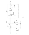
図3は、第1の実施の形態に係るミキサー回路200のブロック図である。
ミキサー回路200は、2つのオーディオ信号をミキシングする。ミキサー回路200は、第1D/Aコンバータ14m、第2D/Aコンバータ14s、反転器201、出力段202を備える。
(First embodiment)
FIG. 3 is a block diagram of the
The
第1D/Aコンバータ14mは、第1デジタルオーディオ信号D1を第1アナログオーディオ信号S1に変換する。反転器201は、第2デジタルオーディオ信号D2の極性を反転し、第3デジタルオーディオ信号D3を生成する。第2D/Aコンバータ14sは、第3デジタルオーディオ信号D3を第2アナログオーディオ信号S2に変換する。
The first D /
出力段202は、第1アナログオーディオ信号S1と第2アナログオーディオ信号S2を逆極性で加算する。本実施の形態において出力段202は、第1アナログオーディオ信号S1と第2アナログオーディオ信号S2の一方(本実施の形態ではS1)から他方(本実施の形態ではS2)を減算する減算回路である。
The
出力段202は、非反転型の減算回路であり、第1演算増幅器OA1、第1抵抗R1〜第4抵抗R4を含む。
分圧回路204は、直列に接続された第1抵抗R1および第2抵抗R2を含む。分圧回路204の一端には、第1アナログオーディオ信号S1と第2アナログオーディオ信号S2の一方(本実施の形態ではS1)が入力され、その他端には基準電圧VREFが入力される。第1抵抗R1と第2抵抗R2の接続点は、第1演算増幅器OA1の非反転入力端子(+)と接続される。第3抵抗R3は、第1演算増幅器OA1の出力端子OUTとその反転入力端子(−)の間に設けられる。第4抵抗R4の一端には、第1アナログオーディオ信号S1と第2アナログオーディオ信号S2の他方(本実施の形態ではS2)が入力され、他端は第1演算増幅器OA1の反転入力端子(−)と接続される。
The
この出力段202によって、第1アナログオーディオ信号S1から第2アナログオーディオ信号S2が減算される。
The
以上がミキサー回路200の構成である。続いてその動作を説明する。
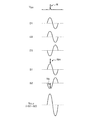
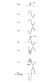
図4は、図3のミキサー回路200の動作波形図である。図4には上から順に、電源電圧VDD、第1デジタルオーディオ信号D1、第2デジタルオーディオ信号D2、第3デジタルオーディオ信号D3、第1アナログオーディオ信号S1、第2アナログオーディオ信号S2、出力信号SOUTが示される。ここでは理解の容易と説明の簡潔化のため、第1デジタルオーディオ信号D1と第2デジタルオーディオ信号D2が同じ波形を有するものとする。
The above is the configuration of the
FIG. 4 is an operation waveform diagram of the
たとえば電源電圧VDDにノイズNが発生したとする。このノイズNが第1D/Aコンバータ14m、第2D/Aコンバータ14sに混入すると、それぞれの出力である第1アナログオーディオ信号S1、第2アナログオーディオ信号S2に、同相ノイズNm、Nsとして現れる。
For example, it is assumed that noise N occurs in the power supply voltage V DD . When this noise N enters the first D /
出力段202によって、第1アナログオーディオ信号S1から第2アナログオーディオ信号S2が減算される。これにより、もとの第1デジタルオーディオ信号D1と第2デジタルオーディオ信号D2が同相で加算されることになる。このとき、ノイズ成分Nm、Nsは逆相で加算されるため、キャンセルすることができる。これにより、ミキサー回路200のS/N比を改善することができる。
The
(第2の実施の形態)
図5は、第2の実施の形態に係るミキサー回路200aのブロック図である。ミキサー回路200aは、図3のミキサー回路200と同様に、2つのオーディオ信号をミキシングする。ミキサー回路200aは、第1D/Aコンバータ14m、第2D/Aコンバータ14s、反転器201、出力段202aを備える。
第1D/Aコンバータ14m、第2D/Aコンバータ14s、反転器201については第1の実施の形態と同様である。
(Second Embodiment)
FIG. 5 is a block diagram of a
The first D /
出力段202aは、反転アンプ210および加算回路220を含む。反転アンプ210は、第1アナログオーディオ信号S1と第2アナログオーディオ信号S2の一方(本実施の形態ではS2)を反転し、第3アナログオーディオ信号S3を生成する。加算回路220は、第1アナログオーディオ信号S1と第2アナログオーディオ信号S2の他方(本実施の形態ではS1)と第3アナログオーディオ信号S3を加算する。
The
加算回路220は、反転型の加算回路220である。加算回路220は、第2演算増幅器OA2、第5抵抗R5〜第7抵抗R7を備える。第2演算増幅器OA2の非反転入力端子(+)には基準電圧VREFが入力される。第5抵抗R5の一端には第1アナログオーディオ信号S1が入力され、他端は第2演算増幅器OA2の反転入力端子(−)と接続される。第6抵抗R6の一端には第3アナログオーディオ信号S3が入力され、他端は第2演算増幅器OA2の反転入力端子(−)と接続される。第7抵抗R7は、第2演算増幅器OA2の出力端子OUTとその反転入力端子(−)の間に設けられる。
The
この加算回路220によって、第1アナログオーディオ信号S1と第2アナログオーディオ信号S2を加算できる。
The adding
反転アンプ210は、第3演算増幅器OA3、第8抵抗R8、第9抵抗R9を備える。第3演算増幅器OA3の非反転入力端子(+)には基準電圧VREFが入力される。第8抵抗R8の一端には第2アナログオーディオ信号S2が入力され、他端は第3演算増幅器OA3の反転入力端子(−)と接続される。第9抵抗R9は、第3演算増幅器OA3の出力端子OUTとその反転入力端子(−)の間に設けられる。
The inverting
以上がミキサー回路200aの構成である。続いてその動作を説明する。
図6は、図5のミキサー回路200aの動作波形図である。図6には上から順に、電源電圧VDD、第1デジタルオーディオ信号D1、第2デジタルオーディオ信号D2、第3デジタルオーディオ信号D3、第1アナログオーディオ信号S1、第2アナログオーディオ信号S2、第3アナログオーディオ信号S3、出力信号SOUTが示される。ここでは理解の容易と説明の簡潔化のため、第1デジタルオーディオ信号D1と第2デジタルオーディオ信号D2が同じ波形を有するものとする。
The above is the configuration of the
FIG. 6 is an operation waveform diagram of the
電源電圧VDDにノイズNが発生したとする。このノイズNが第1D/Aコンバータ14m、第2D/Aコンバータ14sに混入すると、それぞれの出力である第1アナログオーディオ信号S1、第2アナログオーディオ信号S2に、同相ノイズNm、Nsとして現れる。第3アナログオーディオ信号S3に含まれるノイズ成分#Nsは、ノイズNmと逆相になる。
It is assumed that noise N occurs in the power supply voltage V DD . When this noise N enters the first D /
出力段202aによって、第1アナログオーディオ信号S1と第3アナログオーディオ信号S3が加算され、反転増幅される。これにより、もとの第1デジタルオーディオ信号D1と第2デジタルオーディオ信号D2が同相で加算されることになる。このとき、逆相のノイズ成分Nmと#Nsが加算されるため、キャンセルすることができる。これにより、ミキサー回路200aのS/N比を改善することができる。
By the
(技術的思想)
第1の実施の形態および第2の実施の形態から、ミキサー回路のS/N比を改善可能な以下の技術的思想を導くことができる。ミキサー回路200は、少なくとも、第1D/Aコンバータ14mと、第2D/Aコンバータ14sと、出力段202を備える。第1D/Aコンバータ14mにおいて、第1アナログオーディオ信号S1に第1ノイズ成分Nmが重畳され、第2D/Aコンバータ14sにおいて、第2アナログオーディオ信号S2に第1ノイズ成分Nmと同相の第2ノイズ成分Nsが重畳される。ミキサー回路200は、(i)出力段202の出力信号SOUTに含まれる第1オーディオ信号と第2オーディオ信号が同一極性となり、(ii)出力段202の出力信号に含まれる第1ノイズ成分Nsと第2ノイズ成分Nmが逆極性となるように構成される。
(Technical thought)
From the first embodiment and the second embodiment, the following technical idea capable of improving the S / N ratio of the mixer circuit can be derived. The
以上、本発明について、実施の形態をもとに説明した。この実施の形態は例示であり、それらの各構成要素や各処理プロセスの組み合わせにいろいろな変形例が可能なこと、またそうした変形例も本発明の範囲にあることは当業者に理解されるところである。以下、こうした変形例について説明する。 The present invention has been described based on the embodiments. This embodiment is an exemplification, and it will be understood by those skilled in the art that various modifications can be made to combinations of the respective constituent elements and processing processes, and such modifications are within the scope of the present invention. is there. Hereinafter, such modifications will be described.
(第1変形例)
第1の実施の形態(図3)のミキサー回路200において、第1抵抗R1側に第2アナログオーディオ信号S2を入力し、第4抵抗R4側に第1アナログオーディオ信号S1を入力してもよい。言い換えれば、出力段202は、第1アナログオーディオ信号S1と第2アナログオーディオ信号S2の一方S2から他方S1を減算するよう構成されてもよい。
(First modification)
In the
(第2変形例)
また第2の実施の形態(図5)のミキサー回路200aにおいて反転アンプ210は、第1アナログオーディオ信号S1を反転して、第3アナログオーディオ信号S3を生成してもよい。この場合、加算回路220は、第2アナログオーディオ信号S2と第3アナログオーディオ信号S3を加算すればよい。
(Second modification)
In the
(第3変形例)
実施の形態では、ミキシングされる2つのオーディオ信号が、いずれも音声情報を含む場合を説明したが本発明はそれには限定されない。すなわち、ひとつのデジタルオーディオ信号のみを再生する場合であっても、ミキシング機能を有効にしておき、一方の経路に再生したいデジタルオーディオ信号を、もう一方の経路に、情報を含まないつまり無音のデジタルオーディオ信号を入力することで、D/Aコンバータ14で生ずるノイズ成分を好適にキャンセルすることができる。
(Third Modification)
In the embodiment, the case has been described in which both of the two audio signals to be mixed include audio information, but the present invention is not limited to this. That is, even when only one digital audio signal is played, the mixing function is enabled, and the digital audio signal that is to be played back on one path is sent to the other path. By inputting the audio signal, the noise component generated in the D / A converter 14 can be preferably canceled.
(第4変形例)
実施の形態では、オーディオ信号がシングルエンド形式であるものとして説明したが、本発明は差動形式のオーディオ信号にも適用可能である。
(Fourth modification)
In the embodiment, the audio signal has been described as having a single-ended format, but the present invention can also be applied to a differential format audio signal.
(用途)
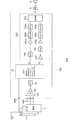
続いてミキサー回路200の具体的な用途を説明する。図7は、ミキサー回路200を備えるオーディオシステム500のブロック図である。図7では、理解の容易化のため、オーディオ信号をモノラルとして示すが、実際には各オーディオ信号はステレオであり、あるいはマルチチャンネルでありうる。また各オーディオ信号は、シングルエンド信号であってもよいし差動信号であってもよい。オーディオシステム500は、音源2、オーディオ信号処理回路100、パワーアンプ8、電気音響変換素子9を備える。
(Use)
Next, a specific application of the
音源2は、CDプレイヤ、ラジオチューナ、ポータブルオーディオデバイスなどであり、アナログまたはデジタルのオーディオ信号を生成する。
The
オーディオ信号処理回路100は、音源2からのオーディオ信号を受け、さまざまな信号処理を行う。パワーアンプ8は、オーディオ信号処理回路100の出力信号を増幅し、電気音響変換素子9を駆動する。電気音響変換素子9はスピーカやヘッドホンである。
The audio
オーディオ信号処理回路100は、ひとつの半導体基板に一体集積化された機能IC(Integrated Circuit)であり、複数の入力端子を有する。デジタル入力端子DINには、CDプレイヤやDVDプレイヤからのデジタルオーディオ信号が入力される。アナログ入力端子AINには、アナログオーディオ信号が入力される。
The audio
オーディオ信号処理回路100は、A/Dコンバータ10、入力セレクタ102、アンプ104、デジタルシグナルプロセッサ12、ミキサー回路200、アンプ106、ポストフィルタ108、アナログボリウム回路110を備える。
The audio
入力セレクタ102は、複数のアナログオーディオ信号からひとつを選択する。アンプ104は、入力セレクタ102の出力信号を、A/Dコンバータ10の入力電圧レンジに適合するように増幅する。
The
A/Dコンバータ10は、入力セレクタ102の出力信号をデジタルオーディオ信号に変換し、デジタルシグナルプロセッサ12に出力する。デジタル入力端子DINに入力されるデジタルオーディオ信号はデジタルシグナルプロセッサ12に直接入力される。
The A /
デジタルシグナルプロセッサ12は、入力されたデジタルのオーディオ信号にさまざまな信号処理を施す。デジタルシグナルプロセッサ12の信号処理は特に限定されないが、たとえば、デジタルボリウム回路、マルチバンドイコライザ、ラウドネス回路、ハイパスフィルタ、ローパスフィルタ、バスブースト回路等を備えてもよい。
The
デジタルシグナルプロセッサ12は、メインのデジタルオーディオ信号D1に加えて、サブのデジタルオーディオ信号D2を出力する。たとえばメインのデジタルオーディオ信号D1は、CDプレイヤやテレビの音声であり、サブのデジタルオーディオ信号D2は、ナビゲーションの音声案内である。ミキサー回路200の構成および動作は上述した通りである。
The
なおミキサー回路200のD/Aコンバータ14と出力段202の間には、アンプ106、ポストフィルタ108、アナログボリウム回路110が挿入される。アンプ106mは、D/Aコンバータ14の出力信号を増幅する。ポストフィルタ108はD/Aコンバータ14の出力をフィルタリングするローパスフィルタである。アナログボリウム回路110は、ポストフィルタ108の出力信号に、ボリウム設定値に応じたゲインを乗ずる。
An amplifier 106, a post filter 108, and an analog volume circuit 110 are inserted between the D / A converter 14 and the
出力段202は、アナログボリウム回路110m、110sの出力を受け、それらを加算もしくは減算する。
The
このオーディオシステム500において、アナログボリウム回路110m、110sのボリウム設定値、つまりゲインは個別に設定可能である。ゲインに大きな差が存在すると、ノイズの効果は低下しうるが、現実的に使用されるボリウム設定値においては、十分な効果が得られる。
In the
図8は、車載用オーディオ装置の斜視図である。オーディオ信号処理回路100およびパワーアンプ8は、オーディオヘッドユニット300としてひとつの筐体に内蔵される。スピーカ9は、フロントドア、リアドアなどに埋め込まれる。オーディオヘッドユニット300には、CDプレイヤやDVDプレイヤからのオーディオ信号が入力される。
FIG. 8 is a perspective view of the in-vehicle audio apparatus. The audio
オーディオシステム500は、車載用オーディオ装置のみでなく、家庭用のホームオーディオシステムのオーディオコンポーネント装置に利用することもできる。あるいはオーディオシステム500は、テレビ、デスクトップPC、ノートPC、タブレットPC、携帯電話端末、デジタルカメラ、ポータブルオーディオプレイヤなどの電子機器に搭載することもできる。
The
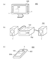
図9(a)〜(c)は、電子機器、オーディオコンポーネント装置の外観図である。図9(a)は電子機器の一例であるディスプレイ装置600である。ディスプレイ装置600は、筐体602、スピーカ9を備える。オーディオ信号処理回路100は筐体に内蔵され、スピーカ9を駆動する。
9A to 9C are external views of an electronic device and an audio component device. FIG. 9A illustrates a
図9(b)はオーディオコンポ700である。オーディオコンポ700は、筐体702、スピーカ9を備える。オーディオ信号処理回路100は筐体702に内蔵され、スピーカ9を駆動する。
FIG. 9B shows an
図9(c)は電子機器の一例である小型情報端末800である。小型情報端末800は、携帯電話、PHS(Personal Handy-phone System)、PDA(Personal Digital Assistant)、タブレットPC(Personal Computer)、オーディオプレイヤなどである。小型情報端末800は、筐体802、スピーカ9、ディスプレイ804を備える。オーディオ信号処理回路100は筐体802に内蔵され、スピーカ9を駆動する。
FIG. 9C illustrates a
実施の形態にもとづき、具体的な語句を用いて本発明を説明したが、実施の形態は、本発明の原理、応用を示しているにすぎず、実施の形態には、請求の範囲に規定された本発明の思想を逸脱しない範囲において、多くの変形例や配置の変更が認められる。 Although the present invention has been described using specific terms based on the embodiments, the embodiments only illustrate the principles and applications of the present invention, and the embodiments are defined in the claims. Many variations and modifications of the arrangement are permitted without departing from the spirit of the present invention.
1…オーディオシステム、2…音源、8…パワーアンプ、9…電気音響変換素子、100…オーディオ信号処理回路、10…A/Dコンバータ、12…デジタルシグナルプロセッサ、14…D/Aコンバータ、200…ミキサー回路、14m…第1D/Aコンバータ、14s…第2D/Aコンバータ、201…反転器、202…出力段、204…分圧回路、210…反転アンプ、220…加算回路、500…オーディオシステム、102…入力セレクタ、104,106…アンプ、108…ポストフィルタ、110…アナログボリウム回路、OA1…第1演算増幅器、OA2…第2演算増幅器、OA3…第3演算増幅器、R1…第1抵抗、R2…第2抵抗、R3…第3抵抗、R4…第4抵抗、R5…第5抵抗、R6…第6抵抗、R7…第7抵抗、R8…第8抵抗、R9…第9抵抗、S1…第1アナログオーディオ信号、S2…第2アナログオーディオ信号、S3…第3アナログオーディオ信号、D1…第1デジタルオーディオ信号、D2…第2デジタルオーディオ信号、D3…第3デジタルオーディオ信号。
DESCRIPTION OF
Claims (19)
第1デジタルオーディオ信号を第1アナログオーディオ信号に変換する第1D/Aコンバータと、
第2デジタルオーディオ信号の極性を反転し、第3デジタルオーディオ信号を生成する反転器と、
前記第3デジタルオーディオ信号を第2アナログオーディオ信号に変換する第2D/Aコンバータと、
前記第1アナログオーディオ信号と前記第2アナログオーディオ信号を逆極性で加算する出力段と、
を備えることを特徴とするミキサー回路。 A mixer circuit for mixing two audio signals,
A first D / A converter for converting a first digital audio signal into a first analog audio signal;
An inverter for inverting the polarity of the second digital audio signal to generate a third digital audio signal;
A second D / A converter for converting the third digital audio signal into a second analog audio signal;
An output stage for adding the first analog audio signal and the second analog audio signal in reverse polarity;
A mixer circuit comprising:
第1演算増幅器と、
直列に接続された第1抵抗および第2抵抗を含み、その一端に前記第1アナログオーディオ信号と前記第2アナログオーディオ信号の一方を受け、その他端に基準電圧を受け、前記第1抵抗と前記第2抵抗の接続点が前記第1演算増幅器の非反転入力端子と接続される分圧回路と、
前記第1演算増幅器の出力端子とその反転入力端子の間に設けられた第3抵抗と、
一端に前記第1アナログオーディオ信号と前記第2アナログオーディオ信号の他方が入力され、他端が前記第1演算増幅器の反転入力端子と接続された第4抵抗と、
を含むことを特徴とする請求項2または3に記載のミキサー回路。 The subtraction circuit
A first operational amplifier;
A first resistor and a second resistor connected in series; one end of which receives one of the first analog audio signal and the second analog audio signal; the other end receives a reference voltage; and the first resistor and the second resistor A voltage dividing circuit in which a connection point of a second resistor is connected to a non-inverting input terminal of the first operational amplifier;
A third resistor provided between the output terminal of the first operational amplifier and its inverting input terminal;
A fourth resistor having one end to which the other of the first analog audio signal and the second analog audio signal is input and the other end connected to an inverting input terminal of the first operational amplifier;
The mixer circuit according to claim 2, wherein the mixer circuit is included.
前記第1アナログオーディオ信号と前記第2アナログオーディオ信号の一方を反転し、第3アナログオーディオ信号を生成する反転アンプと、
前記第1アナログオーディオ信号と前記第2アナログオーディオ信号の他方と前記第3アナログオーディオ信号を加算する加算回路と、
を含むことを特徴とする請求項1に記載のミキサー回路。 The output stage is
An inverting amplifier for inverting one of the first analog audio signal and the second analog audio signal to generate a third analog audio signal;
An addition circuit for adding the other one of the first analog audio signal, the second analog audio signal, and the third analog audio signal;
The mixer circuit according to claim 1, comprising:
非反転入力端子に基準電圧が入力された第2演算増幅器と、
一端に前記第1アナログオーディオ信号と前記第2アナログオーディオ信号の前記他方が入力され、他端が前記第2演算増幅器の反転入力端子と接続された第5抵抗と、
一端に前記第3アナログオーディオ信号が入力され、他端が前記第2演算増幅器の反転入力端子と接続された第6抵抗と、
前記第2演算増幅器の出力端子とその反転入力端子の間に設けられた第7抵抗と、
を含むことを特徴とする請求項5または6に記載のミキサー回路。 The adder circuit
A second operational amplifier in which a reference voltage is input to a non-inverting input terminal;
A fifth resistor having one end to which the other of the first analog audio signal and the second analog audio signal is input and the other end connected to an inverting input terminal of the second operational amplifier;
A sixth resistor in which the third analog audio signal is input to one end and the other end is connected to an inverting input terminal of the second operational amplifier;
A seventh resistor provided between the output terminal of the second operational amplifier and its inverting input terminal;
The mixer circuit according to claim 5, wherein the mixer circuit is included.
非反転入力端子に前記基準電圧が入力された第3演算増幅器と、
一端に前記第1アナログオーディオ信号と前記第2アナログオーディオ信号の前記一方が入力され、他端が前記第3演算増幅器の反転入力端子と接続された第8抵抗と、
前記第3演算増幅器の出力端子とその反転入力端子の間に設けられた第9抵抗と、
を含むことを特徴とする請求項7に記載のミキサー回路。 The inverting amplifier is
A third operational amplifier in which the reference voltage is input to a non-inverting input terminal;
An eighth resistor having one end to which the one of the first analog audio signal and the second analog audio signal is input and the other end connected to the inverting input terminal of the third operational amplifier;
A ninth resistor provided between the output terminal of the third operational amplifier and its inverting input terminal;
The mixer circuit according to claim 7, comprising:
第1デジタルオーディオ信号を第1アナログオーディオ信号に変換する第1D/Aコンバータと、
第2デジタルオーディオ信号を第2アナログオーディオ信号に変換する第2D/Aコンバータと、
前記第1アナログオーディオ信号および前記第2アナログオーディオ信号を加算もしくは減算する出力段と、
を備え、
前記第1D/Aコンバータにおいて、前記第1アナログオーディオ信号に第1ノイズ成分が重畳され、前記第2D/Aコンバータにおいて、前記第2アナログオーディオ信号に前記第1ノイズ成分と同相の第2ノイズ成分が重畳され、
前記ミキサー回路は、(i)前記出力段の出力信号に含まれる第1オーディオ信号と第2オーディオ信号が同一極性となり、(ii)前記出力段の出力信号に含まれる第1ノイズ成分と第2ノイズ成分が逆極性となるように構成されることを特徴とするミキサー回路。 A mixer circuit for mixing two audio signals,
A first D / A converter for converting a first digital audio signal into a first analog audio signal;
A second D / A converter for converting the second digital audio signal into a second analog audio signal;
An output stage for adding or subtracting the first analog audio signal and the second analog audio signal;
With
In the first D / A converter, a first noise component is superimposed on the first analog audio signal, and in the second D / A converter, a second noise component in phase with the first noise component is added to the second analog audio signal. Is superimposed,
In the mixer circuit, (i) the first audio signal and the second audio signal included in the output signal of the output stage have the same polarity, and (ii) the first noise component and the second audio signal included in the output signal of the output stage A mixer circuit configured so that a noise component has a reverse polarity.
をさらに備えることを特徴とする請求項10に記載のオーディオ信号処理回路。 The digital signal processor further comprising: a digital signal processor that performs digital signal processing on each of the plurality of input digital audio signals and outputs the first digital audio signal and the second digital audio signal to the mixer circuit. The audio signal processing circuit according to 1.
前記ミキサー回路の前記第2D/Aコンバータの後段に設けられ、前記第2アナログオーディオ信号にボリウム設定値に応じたゲインを乗算する第2アナログボリウム回路と、
をさらに備えることを特徴とする請求項10または11に記載のオーディオ信号処理回路。 A first analog volume circuit that is provided at a subsequent stage of the first D / A converter of the mixer circuit and multiplies the first analog audio signal by a gain according to a volume setting value;
A second analog volume circuit provided at a stage subsequent to the second D / A converter of the mixer circuit, for multiplying the second analog audio signal by a gain according to a volume setting value;
The audio signal processing circuit according to claim 10, further comprising:
第1D/Aコンバータが第1デジタルオーディオ信号を第1アナログオーディオ信号に変換するステップと、
第2デジタルオーディオ信号の極性を反転し、第3デジタルオーディオ信号を生成するステップと、
第2D/Aコンバータが前記第3デジタルオーディオ信号を第2アナログオーディオ信号に変換するステップと、
前記第1アナログオーディオ信号と前記第2アナログオーディオ信号を逆極性で加算するステップと、
を備えることを特徴とする方法。 A method of mixing two audio signals,
A first D / A converter converting the first digital audio signal to a first analog audio signal;
Inverting the polarity of the second digital audio signal to generate a third digital audio signal;
A second D / A converter converting the third digital audio signal into a second analog audio signal;
Adding the first analog audio signal and the second analog audio signal with opposite polarities;
A method comprising the steps of:
前記第1アナログオーディオ信号と前記第2アナログオーディオ信号の一方を反転し、第3アナログオーディオ信号を生成するステップと、
前記第1アナログオーディオ信号と前記第2アナログオーディオ信号の他方と前記第3アナログオーディオ信号を加算するステップと、
を含むことを特徴とする請求項17に記載の方法。 The step of adding the first analog audio signal and the second analog audio signal with opposite polarities includes:
Inverting one of the first analog audio signal and the second analog audio signal to generate a third analog audio signal;
Adding the other of the first analog audio signal, the second analog audio signal, and the third analog audio signal;
The method of claim 17, comprising:
Priority Applications (2)
| Application Number | Priority Date | Filing Date | Title |
|---|---|---|---|
| JP2014078825A JP2015201729A (en) | 2014-04-07 | 2014-04-07 | Mixer circuit, audio signal processing circuit, audio signal mixing method, on-vehicle audio device using the method, audio component device, and electronic apparatus |
| US14/678,214 US20150289054A1 (en) | 2014-04-07 | 2015-04-03 | Mixer circuit, audio signal processing circuit, method for mixing audio signals, and audio device for a vehicle, audio component device and electronic device using the same |
Applications Claiming Priority (1)
| Application Number | Priority Date | Filing Date | Title |
|---|---|---|---|
| JP2014078825A JP2015201729A (en) | 2014-04-07 | 2014-04-07 | Mixer circuit, audio signal processing circuit, audio signal mixing method, on-vehicle audio device using the method, audio component device, and electronic apparatus |
Related Child Applications (1)
| Application Number | Title | Priority Date | Filing Date |
|---|---|---|---|
| JP2019038359A Division JP6748247B2 (en) | 2019-03-04 | 2019-03-04 | Audio signal processing circuit, vehicle-mounted audio device using the same, audio component device, electronic device |
Publications (1)
| Publication Number | Publication Date |
|---|---|
| JP2015201729A true JP2015201729A (en) | 2015-11-12 |
Family
ID=54210916
Family Applications (1)
| Application Number | Title | Priority Date | Filing Date |
|---|---|---|---|
| JP2014078825A Pending JP2015201729A (en) | 2014-04-07 | 2014-04-07 | Mixer circuit, audio signal processing circuit, audio signal mixing method, on-vehicle audio device using the method, audio component device, and electronic apparatus |
Country Status (2)
| Country | Link |
|---|---|
| US (1) | US20150289054A1 (en) |
| JP (1) | JP2015201729A (en) |
Cited By (2)
| Publication number | Priority date | Publication date | Assignee | Title |
|---|---|---|---|---|
| JP2017126830A (en) * | 2016-01-12 | 2017-07-20 | ローム株式会社 | Audio digital signal processing device, on-vehicle audio device using the same, and electronic equipment |
| KR20220082837A (en) | 2019-10-18 | 2022-06-17 | 로무 가부시키가이샤 | audio circuit |
Families Citing this family (3)
| Publication number | Priority date | Publication date | Assignee | Title |
|---|---|---|---|---|
| GB2563296B (en) * | 2017-06-06 | 2022-01-12 | Cirrus Logic Int Semiconductor Ltd | Systems, apparatus and methods for dynamic range enhancement of audio signals |
| US11070183B1 (en) | 2020-03-31 | 2021-07-20 | Cirrus Logic, Inc. | Systems, apparatus and methods for dynamic range enhancement of audio signals |
| CN114007167B (en) * | 2021-10-29 | 2023-08-25 | 中电科航空电子有限公司 | Analog audio two-way communication system and communication method |
Citations (3)
| Publication number | Priority date | Publication date | Assignee | Title |
|---|---|---|---|---|
| JPS63256020A (en) * | 1987-04-13 | 1988-10-24 | Matsushita Electric Ind Co Ltd | Digital/analog converter |
| JPH05308286A (en) * | 1992-05-06 | 1993-11-19 | Nec Eng Ltd | D/a converter |
| JP2008244721A (en) * | 2007-03-27 | 2008-10-09 | Clarion Co Ltd | Voice mixing circuit |
Family Cites Families (2)
| Publication number | Priority date | Publication date | Assignee | Title |
|---|---|---|---|---|
| US6150970A (en) * | 1999-03-01 | 2000-11-21 | Sony Corporation | Method and system for digital to analog conversion |
| GB2366709A (en) * | 2000-06-30 | 2002-03-13 | Graeme Roy Smith | Modular software definable pre-amplifier |
-
2014
- 2014-04-07 JP JP2014078825A patent/JP2015201729A/en active Pending
-
2015
- 2015-04-03 US US14/678,214 patent/US20150289054A1/en not_active Abandoned
Patent Citations (3)
| Publication number | Priority date | Publication date | Assignee | Title |
|---|---|---|---|---|
| JPS63256020A (en) * | 1987-04-13 | 1988-10-24 | Matsushita Electric Ind Co Ltd | Digital/analog converter |
| JPH05308286A (en) * | 1992-05-06 | 1993-11-19 | Nec Eng Ltd | D/a converter |
| JP2008244721A (en) * | 2007-03-27 | 2008-10-09 | Clarion Co Ltd | Voice mixing circuit |
Cited By (3)
| Publication number | Priority date | Publication date | Assignee | Title |
|---|---|---|---|---|
| JP2017126830A (en) * | 2016-01-12 | 2017-07-20 | ローム株式会社 | Audio digital signal processing device, on-vehicle audio device using the same, and electronic equipment |
| KR20220082837A (en) | 2019-10-18 | 2022-06-17 | 로무 가부시키가이샤 | audio circuit |
| DE112020004969T5 (en) | 2019-10-18 | 2022-06-30 | Rohm Co. Ltd. | AUDIO CIRCUIT |
Also Published As
| Publication number | Publication date |
|---|---|
| US20150289054A1 (en) | 2015-10-08 |
Similar Documents
| Publication | Publication Date | Title |
|---|---|---|
| US9143104B2 (en) | Audio signal processing circuit, car audio apparatus using the same, audio component apparatus, electronic device and output audio signal generating method | |
| JP2015201729A (en) | Mixer circuit, audio signal processing circuit, audio signal mixing method, on-vehicle audio device using the method, audio component device, and electronic apparatus | |
| US9380388B2 (en) | Channel crosstalk removal | |
| JP6510199B2 (en) | Switching circuit, audio amplifier integrated circuit, electronic device, driving method of electroacoustic transducer | |
| JPWO2007029737A1 (en) | Balanced amplifier and electronic circuit | |
| KR102181830B1 (en) | Stereo audio system and method | |
| JP2016208361A (en) | Audio circuit, on-vehicle audio device using the same, audio component device, and electronic equipment | |
| CN109120269B (en) | Digital-analog converter | |
| JP6748247B2 (en) | Audio signal processing circuit, vehicle-mounted audio device using the same, audio component device, electronic device | |
| JP6090395B1 (en) | Music player | |
| US20190131947A1 (en) | Audio circuit | |
| JP6018491B2 (en) | D / A conversion circuit, zero cross point detection method, in-vehicle audio apparatus, audio component apparatus, and electronic apparatus using the same | |
| JP6385529B2 (en) | Audio signal processing circuit, audio signal processing method, in-vehicle audio device using the same, audio component device, and electronic device | |
| JP5032367B2 (en) | Audio signal processing circuit | |
| JP6310317B2 (en) | Microphone bias circuit, audio interface circuit, electronic equipment | |
| US20050152556A1 (en) | Passive surround sound adapter | |
| JP6027444B2 (en) | Audio signal processing circuit and in-vehicle audio apparatus, audio component apparatus, and electronic device using the same | |
| US11830523B2 (en) | Audio mixing device and audio mixing method | |
| CN116055950B (en) | Speaker driving circuit and electronic device | |
| US10542345B2 (en) | Virtual bass generating circuit and method | |
| JP2012501560A (en) | Reducing disturbance in the output signal of the multiport connector | |
| JP6474246B2 (en) | Audio signal processing circuit, in-vehicle audio device, audio component device, electronic equipment | |
| US9941848B1 (en) | Transconductance with capacitances feedback compensation amplifier | |
| JPH04115799A (en) | Speaker changeover circuit | |
| CN115967358A (en) | Audio power amplifier and electronic equipment |
Legal Events
| Date | Code | Title | Description |
|---|---|---|---|
| A621 | Written request for application examination |
Free format text: JAPANESE INTERMEDIATE CODE: A621 Effective date: 20170317 |
|
| A977 | Report on retrieval |
Free format text: JAPANESE INTERMEDIATE CODE: A971007 Effective date: 20180302 |
|
| A131 | Notification of reasons for refusal |
Free format text: JAPANESE INTERMEDIATE CODE: A131 Effective date: 20180417 |
|
| A521 | Request for written amendment filed |
Free format text: JAPANESE INTERMEDIATE CODE: A523 Effective date: 20180615 |
|
| A02 | Decision of refusal |
Free format text: JAPANESE INTERMEDIATE CODE: A02 Effective date: 20181204 |