JP2015200401A - Handle operation device and valve device - Google Patents
Handle operation device and valve device Download PDFInfo
- Publication number
- JP2015200401A JP2015200401A JP2014089608A JP2014089608A JP2015200401A JP 2015200401 A JP2015200401 A JP 2015200401A JP 2014089608 A JP2014089608 A JP 2014089608A JP 2014089608 A JP2014089608 A JP 2014089608A JP 2015200401 A JP2015200401 A JP 2015200401A
- Authority
- JP
- Japan
- Prior art keywords
- opening
- valve
- closing operation
- handle
- operation body
- Prior art date
- Legal status (The legal status is an assumption and is not a legal conclusion. Google has not performed a legal analysis and makes no representation as to the accuracy of the status listed.)
- Pending
Links
Images

Abstract
Description
この発明は、ハンドル操作装置及びバルブ装置に関する。 The present invention relates to a handle operating device and a valve device.
農業用の配水管においては、所定の時期、時刻において配水用バルブが開かれて田畑に水が供給される。このバルブは戸外に設置されており、いたずらによって、また誤って操作ハンドルが操作され開かれて配水が行われると、田畑に大きな被害が発生する。逆に配水用バルブが開かれ継続的に水が供給されなければならない際に、同様にして閉じられ配水が停止されてもやはり被害が生じる。また、工場内では製造ラインにおいて液体や気体が配管を通して供給されるが、バルブが誤って開かれると製造に支障をきたすとともに、大きな事故となる恐れもある。 In an agricultural water distribution pipe, a water distribution valve is opened at a predetermined time and time to supply water to the field. This valve is installed outdoors, and if the control handle is accidentally operated and opened to distribute water by mischief, water damage will occur. Conversely, when the water distribution valve is opened and water must be continuously supplied, even if the water distribution is stopped in the same manner and the water distribution is stopped, damage is still caused. In addition, liquids and gases are supplied through pipes in the production line in the factory, but if the valve is opened by mistake, the production may be hindered and a serious accident may occur.
上記の問題に対応すべく、例えば、バルブの操作ハンドルにチェーンを巻き付ける等して固定することが行われている。しかしながら、その取り付け固定、取り外しに手間がかかり、見栄えも悪い。また、故意にチェーンを切断して操作ハンドルを操作することも可能である。 In order to cope with the above problem, for example, a chain is wound around the operation handle of the valve and fixed. However, it takes time and effort to fix and remove it, and the appearance is poor. It is also possible to intentionally cut the chain and operate the operation handle.
この発明は上記の点に鑑みて行ったもので、バルブを必要時のみにおいて開閉操作できるようして、バルブの安全性を高めること等を目的としてなしたものである。 The present invention has been made in view of the above points, and is intended to increase the safety of the valve so that the valve can be opened and closed only when necessary.
請求項1の発明では、操作ハンドルの操作に連動して回転軸を回転させるハンドル操作装置において、施錠手段と、前記施錠手段の施錠時において前記操作ハンドルから前記回転軸部を離脱させて前記回転軸を空転させる空転手段とを設けてなることを特徴とするハンドル操作装置を提供する。 According to the first aspect of the present invention, in the handle operating device that rotates the rotating shaft in conjunction with the operation of the operating handle, the rotating means is detached from the operating handle when the locking means is locked and the rotation is performed. Provided is a handle operating device characterized by comprising an idling means for idling a shaft.
上記構成によれば、施錠手段による施錠時により操作ハンドルから回転軸が離脱し、回転軸は空転する。これにより操作ハンドルを回転操作しても回転軸端に備えられる各種の機能を持つ作動体の作動が行われない。ハンドル操作装置は回転軸端に適宜の作動体を備える構成とすることで各種の装置、機器、機構に一体に組み込まれて使用される。例えば、作動体として弁体を使用することでバルブ装置に使用され、作動体としてロック片を使用することで各種装置のロック機構に使用される。 According to the above configuration, the rotating shaft is detached from the operation handle when the locking means is locked, and the rotating shaft is idled. Thereby, even if the operation handle is rotated, the operation body having various functions provided at the end of the rotation shaft is not operated. The handle operating device is used by being incorporated in various devices, devices, and mechanisms by providing an appropriate operating body at the end of the rotating shaft. For example, it is used for a valve device by using a valve body as an operating body, and is used for a locking mechanism of various devices by using a lock piece as an operating body.
請求項2の発明では、管内流路を開閉する弁体と、前記弁体を開閉作動させる開閉作動体と、前記開閉作動体を作動させる開閉操作体とを備えるバルブ装置において、施錠手段と、前記施錠手段の施錠に連動して前記開閉作動体と開閉操作体とを離脱させて、前記開閉操作体による前記開閉作動体の作動を阻止する作動阻止手段とを備えることを特徴とするバルブ装置を提供する。 According to a second aspect of the present invention, in a valve device comprising: a valve body that opens and closes a flow path in a pipe; an opening and closing operation body that opens and closes the valve body; and an opening and closing operation body that operates the opening and closing operation body. A valve device comprising: an operation blocking means for detaching the opening / closing operation body and the opening / closing operation body in conjunction with locking of the locking means to block the operation of the opening / closing operation body by the opening / closing operation body. I will provide a.
上記構成によれば、施錠手段の施錠に連動して開閉作動体と開閉操作体とが離脱され、開閉操作体による開閉作動体の作動が阻止され、弁体が開閉作動されることがない。すなわち、開閉操作体が操作されても開閉作動体は作動せず、弁体が開閉作動されない。鍵が使用されて施錠手段が開錠された場合のみ、開閉操作体を操作することで開閉作動体が作動され、弁体の開閉が可能となる。 According to the above configuration, the opening / closing operation body and the opening / closing operation body are detached in conjunction with the locking of the locking means, the operation of the opening / closing operation body by the opening / closing operation body is prevented, and the valve body is not opened / closed. That is, even when the opening / closing operation body is operated, the opening / closing operation body does not operate, and the valve body does not open / close. Only when the key is used and the locking means is unlocked, the opening / closing operation body is operated by operating the opening / closing operation body, and the valve body can be opened / closed.
この発明によれば、ハンドル操作を行っての各種装置の作動が、鍵を使用して開錠した場合のみ安全に行えるようになる。また、鍵を使用して開錠した場合のみ開閉操作体を使用しての弁体の開閉が行え、安全性の高いバルブ装置が得られる。 According to the present invention, the operation of various devices by operating the handle can be performed safely only when unlocked using the key. Moreover, the valve body can be opened and closed using the opening / closing operation body only when unlocked using the key, and a highly safe valve device can be obtained.
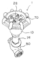
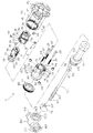
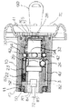
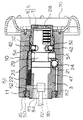
図1はこの発明のバルブ装置の外観斜視図、図2は同分解図、図3は同施錠時の部分拡大断面構成図、図4は同開錠時の部分拡大断面構成図である。 1 is an external perspective view of the valve device of the present invention, FIG. 2 is an exploded view thereof, FIG. 3 is a partially enlarged cross-sectional configuration diagram at the time of locking, and FIG. 4 is a partially enlarged cross-sectional configuration diagram at the time of unlocking.
バルブ装置1は全体が金属製で、操作ハンドル(開閉操作体)70、操作ハンドル70が前面に固定される筒状外嵌部材10、内筒部材7と外筒部材8とからなり筒状外嵌部材10内の前部に配置されるシリンダー錠(施錠手段)5、筒状外嵌部材10内の後部に配置される作動筒部材3、作動筒部材3に上端が固定され筒状外嵌部材10から後方に突出する作動ロッド(回転軸または開閉作動体)72、作動ロッド72に外嵌される外嵌筒材74、作動ロッド72の下端に取り付けられる弁体76、弁体76が内部に配置される管体80とから構成される。上記筒状外嵌部材10と作動筒部材3とにより空転手段または作動阻止手段が構成される。 The valve device 1 is entirely made of metal, and includes an operation handle (opening / closing operation body) 70, a cylindrical
作動筒部材3は後部側の円孔15の前部に連続して円形の凹部17が形成されて構成されている。円孔15の側部81には相対する位置にピン固定穴82のそれぞれが設けられ、ピン固定穴82それぞれに固定ピン83が圧入固定され、固定ピン83に前端部84の固定ピン係止孔85が挿通されることで作動ロッド72が取り付けられている。円形凹部17の側部16には前後方向に前面が開口する細径の装着穴19が3本形成され、さらに、それら装着穴19の間位置には装着孔21が3個形成され、装着穴19のそれぞれにはコイルバネ22と作動ピン23とのそれぞれが、装着孔21のそれぞれにはラッチボール24のそれぞれが装着される。 The actuating
シリンダー錠5の内筒部材7は、錠本体部26の後面に柱状部27が一体に突出して設けられ、柱状部27の周囲には納め溝29が環状に設けられている。錠本体部26は前面に鍵差し入れ穴28を備えるとともに、外周面には外筒部材8側に係合する凸条30が設けられ、さらに柱状部27に近い側には相対する2カ所の位置に納め溝32のそれぞれが周方向に沿って設けられている。 In the inner cylinder member 7 of the cylinder lock 5, a
シリンダー錠5の外筒部材8は前部の細径部36と後部の太径部37とからなり、細径部36の前面に錠の操作開口35を備え、後部の太径部37はその周囲の互いに相対する位置に2個の装着穴38を備え、さらに互い相対する位置に2個のピン固定穴39を備えるとともに、細径部36と太径部37との連続する内周面には軸方向に係合溝41が設けられている。 The outer
シリンダー錠5は、図3に示す施錠時においては、ラッチボール42のそれぞれが内筒部材7の納め溝32のそれぞれから外方に外れ、外筒部材8のピン固定穴39から嵌合挿入された固定ピン44の先端部それぞれが納め溝32内に位置し、さらに、外筒部材8の係合溝41に内筒部材7の凸条30が係合する状態において一体となっている。内筒部材7と外筒部材8とは互いに係合しないので別途回転が可能とされ、固定ピン44が納め溝32内に位置していることで前後へのスライド移動は一体に行われ、かつ、内筒部材7が外筒部材8から抜け出ることがないようになっている。 In the locking shown in FIG. 3, each of the
筒状外嵌部材10は後面が開放するとともに前面に操作ハンドル70が取り付けられ、後部周縁の内側にネジ部45が設けられ、後部側の内周面には軸方向に3本の係合溝47が設けられている。 The tubular
作動ロッド72は、上記したように固定ピン係止孔85が設けられた太い径の前端部84を備えるとともに、その後部側にネジ部90を備え、後端には弁体76の係止部93を備えている。 The
外嵌筒材74は作動ロッド72が挿通される連通穴92を備え、その連通穴92の内面には作動ロッド72のネジ部90と螺合するネジ部96(図5参照)を備え、後部には周面にネジ部94を備える連結管部95が突出して設けられている。 The
弁体76は円形で、その周面の一部に作動ロッド72の係止部93が係止される係止凹所97を備えている。 The
管体80は前面中央に弁体76が差し入れられる開口100を備え、両端に流路配管の接続開口101のそれぞれを備え、それぞれの開口100、101内周面には連結用のネジ部103、104のそれぞれが設けられている。 The
バルブ装置1の組み立ては、筒状外嵌部材10の後面からシリンダー錠5と作動ロッド72が取り付けられた作動筒部材3とが順次所定の位置関係において差し入れられ、ネジ部45とネジ部50とが螺着されて抜け止め部材11が装着され、抜け止め部材11に作動筒部材3の角部52が当たることで作動筒部材3及びシリンダー錠5が筒状外嵌部材10内から抜け出ることがないようになっている。図5に示すように、筒状外嵌部材10から突出する作動ロッド72は外嵌筒材74の挿通穴92内に挿入され、作動ロッド72に対して外嵌筒材74が相対的に回転されることでネジ部90とネジ部96とが螺合し、さらに回転されることで作動ロッド72後端の係止部93が外嵌筒材74の連結管部95から突出し、その係止部93に係止凹所97が係止されることで弁体76が取り付けられる。外嵌筒材74はその連結管部95のネジ部94がネジ部103に螺着されることで開口100に差し入れられて管体80に連結され、その連結された状態において弁体76が管体80内の流路Rを開閉可能に位置する。 The valve device 1 is assembled by inserting the cylinder lock 5 and the
以下、動作説明を行う。図3に示す施錠時においては、内筒部材7の納め溝32から外方に外れて位置するラッチボール42のそれぞれが筒錠カバー部材10の内面の係合面54に係止する位置にあり、シリンダー錠5は作動筒部材3のコイルバネ22で付勢される作動ピン23の先端に外筒部材8の後面が押されることで前方側に付勢されている。また、この状態においては、装着穴21内に位置するラッチボール24のそれぞれはシリンダー錠5の内筒部7の納め溝29に相対する位置にある。ラッチボール24のそれぞれは納め溝29内に入り込むことで筒状外嵌部材10の係合溝47のそれぞれに係合せず、これにより筒状外嵌部材10はその回転方向において作動筒部材3と離脱している。したがって、施錠状態においては操作ハンドル70を回転操作しても筒状外嵌部材10が「空回り」して作動筒部材3が回転せず、これにより作動ロッド72も回転しないことで水平に移動することはなく、それに一体の弁体76が管体80内の流路を開閉することはない。 The operation will be described below. At the time of locking shown in FIG. 3, each of the
図3に示す施錠状態において、鍵60をシリンダー錠5の内筒部材7の鍵差し入れ穴28から差し入れて回転させると、凸条30が外筒部材8の係合溝41から外れて内筒部材7が回転し、これにより、図4に示すように、ラッチボール42のそれぞれは相対して位置する内筒部材7の納め溝32それぞれに入り込むことが可能となる。その状態において作動ピン23で外筒部材8が押されると、納め溝32それぞれに入り込むことでラッチボール42それぞれの筒状外嵌部材10の係合面54への係合が解除されてシリンダー部材5は全体が前方に移動する。この移動に伴って内筒部材7の納め溝29も前方に移動することでそこにあったラッチボール24はともに押し出されて装着穴21内から外方に突出し、筒状外嵌部材10の内面の係合溝47に係合する状態となる。 In the locked state shown in FIG. 3, when the key 60 is inserted through the
このように作動筒部材3の装着孔21内それぞれに位置する3個のラッチボール24のそれぞれが係合溝47のそれぞれに係合することで、筒状外嵌部材10は作動筒部材3に回転方向において固定されて「空回り」できなくなる。この状態において、操作ハンドル70を回転操作すると筒状外嵌部材10とともに作動筒部材3が回転し、これにより作動ロッド72が回転してネジ部90とネジ部96が螺合していることで作動ロッド72は水平に移動し、それに一体の弁体76も管体80内で水平に移動して流路の開閉を行う。 As described above, the three
図5において、実線が、弁体76が管体80内の流路Rを閉じる状態で、この状態で、開錠により図4に示す筒状外嵌部材10と作動筒部材3とが固定された状態とされ、操作ハンドル70が一方の方向に回転操作されることで作動ロッド72は右側に移動してその右側部分が外嵌筒材74から突出し、これにより点線で示すように弁体76も移動して管体80内の流路Rを開く状態となる。流路Rが開かれた状態において、操作ハンドル70が他方の方向に回転操作されることで上記と逆の動作が行われて、流路Rは閉じられる。 In FIG. 5, the solid line indicates a state in which the
3 作動筒部材(空転手段または作動阻止手段)
5 シリンダー錠(施錠手段)
10 筒状外嵌部材(空転手段または作動阻止手段)
70 操作ハンドル(開閉操作体)
72 作動ロッド(回転軸または開閉作動体)
R 管内流路3 Actuating cylinder member (idling means or action preventing means)
5 Cylinder lock (locking means)
10 Cylindrical outer fitting member (idling means or operation preventing means)
70 Operation handle (open / close operation body)
72 Actuating rod (rotating shaft or opening / closing actuator)
R Pipe flow path
Claims (2)
施錠手段と、
前記施錠手段の施錠時において前記操作ハンドルから前記回転軸部を離脱させて前記回転軸を空転させる空転手段と、
を設けてなることを特徴とするハンドル操作装置。In the handle operating device that rotates the rotating shaft in conjunction with the operation of the operation handle,
Locking means;
Idle rotation means for causing the rotation shaft to idle by detaching the rotation shaft portion from the operation handle at the time of locking the locking means;
A handle operating device comprising:
施錠手段と、
前記施錠手段の施錠に連動して前記開閉作動体と開閉操作体とを離脱させて、前記開閉操作体による前記開閉作動体の作動を阻止する作動阻止手段と、
を備えることを特徴とするバルブ装置。In a valve device comprising: a valve body that opens and closes a flow path in a pipe; an opening and closing operation body that opens and closes the valve body; and an opening and closing operation body that operates the opening and closing operation body.
Locking means;
An operation blocking means for detaching the opening / closing operation body and the opening / closing operation body in conjunction with locking of the locking means and blocking the operation of the opening / closing operation body by the opening / closing operation body;
A valve device comprising:
Priority Applications (1)
| Application Number | Priority Date | Filing Date | Title |
|---|---|---|---|
| JP2014089608A JP2015200401A (en) | 2014-04-07 | 2014-04-07 | Handle operation device and valve device |
Applications Claiming Priority (1)
| Application Number | Priority Date | Filing Date | Title |
|---|---|---|---|
| JP2014089608A JP2015200401A (en) | 2014-04-07 | 2014-04-07 | Handle operation device and valve device |
Related Child Applications (1)
| Application Number | Title | Priority Date | Filing Date |
|---|---|---|---|
| JP2018002452U Continuation JP3219255U (en) | 2018-06-11 | 2018-06-11 | Valve device |
Publications (1)
| Publication Number | Publication Date |
|---|---|
| JP2015200401A true JP2015200401A (en) | 2015-11-12 |
Family
ID=54551831
Family Applications (1)
| Application Number | Title | Priority Date | Filing Date |
|---|---|---|---|
| JP2014089608A Pending JP2015200401A (en) | 2014-04-07 | 2014-04-07 | Handle operation device and valve device |
Country Status (1)
| Country | Link |
|---|---|
| JP (1) | JP2015200401A (en) |
Cited By (2)
| Publication number | Priority date | Publication date | Assignee | Title |
|---|---|---|---|---|
| JP2018204667A (en) * | 2017-06-01 | 2018-12-27 | 株式会社ガードロック | Handle for valve with lock mechanism |
| JP7304052B2 (en) | 2019-02-01 | 2023-07-06 | 株式会社ガードロック | Handle for valve with locking mechanism |
Citations (5)
| Publication number | Priority date | Publication date | Assignee | Title |
|---|---|---|---|---|
| JPS63132183U (en) * | 1987-02-23 | 1988-08-30 | ||
| JPS6444977U (en) * | 1987-09-12 | 1989-03-17 | ||
| JPH02285411A (en) * | 1989-03-30 | 1990-11-22 | Vickers Syst Ltd | Lockable controller |
| JPH05231562A (en) * | 1992-02-20 | 1993-09-07 | Kiyohara Masako | Handle for valve operation |
| JP3181718U (en) * | 2012-11-20 | 2013-02-21 | 株式会社ガードロック | Nut member removal prevention device |
-
2014
- 2014-04-07 JP JP2014089608A patent/JP2015200401A/en active Pending
Patent Citations (5)
| Publication number | Priority date | Publication date | Assignee | Title |
|---|---|---|---|---|
| JPS63132183U (en) * | 1987-02-23 | 1988-08-30 | ||
| JPS6444977U (en) * | 1987-09-12 | 1989-03-17 | ||
| JPH02285411A (en) * | 1989-03-30 | 1990-11-22 | Vickers Syst Ltd | Lockable controller |
| JPH05231562A (en) * | 1992-02-20 | 1993-09-07 | Kiyohara Masako | Handle for valve operation |
| JP3181718U (en) * | 2012-11-20 | 2013-02-21 | 株式会社ガードロック | Nut member removal prevention device |
Cited By (2)
| Publication number | Priority date | Publication date | Assignee | Title |
|---|---|---|---|---|
| JP2018204667A (en) * | 2017-06-01 | 2018-12-27 | 株式会社ガードロック | Handle for valve with lock mechanism |
| JP7304052B2 (en) | 2019-02-01 | 2023-07-06 | 株式会社ガードロック | Handle for valve with locking mechanism |
Similar Documents
| Publication | Publication Date | Title |
|---|---|---|
| WO2016021612A1 (en) | Lock mechanism for tubular body | |
| US9926064B1 (en) | Latching apparatuses for cowls on outboard marine engines | |
| JP2015200401A (en) | Handle operation device and valve device | |
| JP3219255U (en) | Valve device | |
| KR101876258B1 (en) | Cap for rotating steering wheel | |
| JP5979787B2 (en) | Cylinder lock | |
| JP3229603U (en) | Valve device | |
| HK1074069A1 (en) | A connection device for an end of a control cable | |
| ITMI20140212U1 (en) | LOCK FOR FIELD GENERATORS | |
| JP6931147B2 (en) | Handle for valve with lock mechanism | |
| JP6095602B2 (en) | Anti-theft faucet | |
| JP6999278B2 (en) | Faucet with handle and handle | |
| US10876320B2 (en) | Locking device with lockable spindle follower linkage | |
| GB2504451A (en) | Door handle structure with two handles having independent idle functions | |
| JP2009204053A (en) | Lock device for rotary valve lever handle | |
| TW201610282A (en) | Pop-out type lock handle device for door | |
| JP6663794B2 (en) | Purge structure in gas tap | |
| KR20010049957A (en) | Double locking device | |
| JP7402472B2 (en) | Opening position fixer | |
| JP2014163396A (en) | Emergency cutoff valve | |
| KR200342572Y1 (en) | Ball valve lock | |
| JP2009036228A (en) | Gas cock | |
| JP4272509B2 (en) | Locking device for valve operating member | |
| CN104595567A (en) | Lock valve cover and corresponding lock valve | |
| GB2511397A (en) | Lock device |
Legal Events
| Date | Code | Title | Description |
|---|---|---|---|
| A621 | Written request for application examination |
Free format text: JAPANESE INTERMEDIATE CODE: A621 Effective date: 20170406 |
|
| A977 | Report on retrieval |
Free format text: JAPANESE INTERMEDIATE CODE: A971007 Effective date: 20180226 |
|
| A131 | Notification of reasons for refusal |
Free format text: JAPANESE INTERMEDIATE CODE: A131 Effective date: 20180306 |