JP2015197329A - Data transmission system, data transmission apparatus, data transmission method and data transmission program - Google Patents
Data transmission system, data transmission apparatus, data transmission method and data transmission program Download PDFInfo
- Publication number
- JP2015197329A JP2015197329A JP2014074378A JP2014074378A JP2015197329A JP 2015197329 A JP2015197329 A JP 2015197329A JP 2014074378 A JP2014074378 A JP 2014074378A JP 2014074378 A JP2014074378 A JP 2014074378A JP 2015197329 A JP2015197329 A JP 2015197329A
- Authority
- JP
- Japan
- Prior art keywords
- data
- point cloud
- data transmission
- cloud data
- area
- Prior art date
- Legal status (The legal status is an assumption and is not a legal conclusion. Google has not performed a legal analysis and makes no representation as to the accuracy of the status listed.)
- Pending
Links
Images


Classifications
-
- G—PHYSICS
- G05—CONTROLLING; REGULATING
- G05B—CONTROL OR REGULATING SYSTEMS IN GENERAL; FUNCTIONAL ELEMENTS OF SUCH SYSTEMS; MONITORING OR TESTING ARRANGEMENTS FOR SUCH SYSTEMS OR ELEMENTS
- G05B19/00—Programme-control systems
- G05B19/02—Programme-control systems electric
- G05B19/04—Programme control other than numerical control, i.e. in sequence controllers or logic controllers
- G05B19/048—Monitoring; Safety
-
- G—PHYSICS
- G08—SIGNALLING
- G08C—TRANSMISSION SYSTEMS FOR MEASURED VALUES, CONTROL OR SIMILAR SIGNALS
- G08C17/00—Arrangements for transmitting signals characterised by the use of a wireless electrical link
-
- B—PERFORMING OPERATIONS; TRANSPORTING
- B25—HAND TOOLS; PORTABLE POWER-DRIVEN TOOLS; MANIPULATORS
- B25J—MANIPULATORS; CHAMBERS PROVIDED WITH MANIPULATION DEVICES
- B25J9/00—Programme-controlled manipulators
- B25J9/16—Programme controls
- B25J9/1679—Programme controls characterised by the tasks executed
- B25J9/1689—Teleoperation
-
- G—PHYSICS
- G01—MEASURING; TESTING
- G01S—RADIO DIRECTION-FINDING; RADIO NAVIGATION; DETERMINING DISTANCE OR VELOCITY BY USE OF RADIO WAVES; LOCATING OR PRESENCE-DETECTING BY USE OF THE REFLECTION OR RERADIATION OF RADIO WAVES; ANALOGOUS ARRANGEMENTS USING OTHER WAVES
- G01S17/00—Systems using the reflection or reradiation of electromagnetic waves other than radio waves, e.g. lidar systems
- G01S17/02—Systems using the reflection of electromagnetic waves other than radio waves
- G01S17/06—Systems determining position data of a target
- G01S17/42—Simultaneous measurement of distance and other co-ordinates
-
- G—PHYSICS
- G01—MEASURING; TESTING
- G01S—RADIO DIRECTION-FINDING; RADIO NAVIGATION; DETERMINING DISTANCE OR VELOCITY BY USE OF RADIO WAVES; LOCATING OR PRESENCE-DETECTING BY USE OF THE REFLECTION OR RERADIATION OF RADIO WAVES; ANALOGOUS ARRANGEMENTS USING OTHER WAVES
- G01S17/00—Systems using the reflection or reradiation of electromagnetic waves other than radio waves, e.g. lidar systems
- G01S17/88—Lidar systems specially adapted for specific applications
- G01S17/89—Lidar systems specially adapted for specific applications for mapping or imaging
-
- G—PHYSICS
- G01—MEASURING; TESTING
- G01S—RADIO DIRECTION-FINDING; RADIO NAVIGATION; DETERMINING DISTANCE OR VELOCITY BY USE OF RADIO WAVES; LOCATING OR PRESENCE-DETECTING BY USE OF THE REFLECTION OR RERADIATION OF RADIO WAVES; ANALOGOUS ARRANGEMENTS USING OTHER WAVES
- G01S7/00—Details of systems according to groups G01S13/00, G01S15/00, G01S17/00
- G01S7/003—Transmission of data between radar, sonar or lidar systems and remote stations
-
- G—PHYSICS
- G01—MEASURING; TESTING
- G01S—RADIO DIRECTION-FINDING; RADIO NAVIGATION; DETERMINING DISTANCE OR VELOCITY BY USE OF RADIO WAVES; LOCATING OR PRESENCE-DETECTING BY USE OF THE REFLECTION OR RERADIATION OF RADIO WAVES; ANALOGOUS ARRANGEMENTS USING OTHER WAVES
- G01S7/00—Details of systems according to groups G01S13/00, G01S15/00, G01S17/00
- G01S7/48—Details of systems according to groups G01S13/00, G01S15/00, G01S17/00 of systems according to group G01S17/00
- G01S7/4808—Evaluating distance, position or velocity data
-
- G—PHYSICS
- G05—CONTROLLING; REGULATING
- G05B—CONTROL OR REGULATING SYSTEMS IN GENERAL; FUNCTIONAL ELEMENTS OF SUCH SYSTEMS; MONITORING OR TESTING ARRANGEMENTS FOR SUCH SYSTEMS OR ELEMENTS
- G05B2219/00—Program-control systems
- G05B2219/20—Pc systems
- G05B2219/23—Pc programming
- G05B2219/23098—Manual control, via microprocessor instead of direct connection to actuators
-
- G—PHYSICS
- G05—CONTROLLING; REGULATING
- G05B—CONTROL OR REGULATING SYSTEMS IN GENERAL; FUNCTIONAL ELEMENTS OF SUCH SYSTEMS; MONITORING OR TESTING ARRANGEMENTS FOR SUCH SYSTEMS OR ELEMENTS
- G05B2219/00—Program-control systems
- G05B2219/30—Nc systems
- G05B2219/37—Measurements
- G05B2219/37567—3-D vision, stereo vision, with two cameras
-
- G—PHYSICS
- G05—CONTROLLING; REGULATING
- G05B—CONTROL OR REGULATING SYSTEMS IN GENERAL; FUNCTIONAL ELEMENTS OF SUCH SYSTEMS; MONITORING OR TESTING ARRANGEMENTS FOR SUCH SYSTEMS OR ELEMENTS
- G05B2219/00—Program-control systems
- G05B2219/30—Nc systems
- G05B2219/40—Robotics, robotics mapping to robotics vision
- G05B2219/40169—Display of actual situation at the remote site
-
- G—PHYSICS
- G08—SIGNALLING
- G08C—TRANSMISSION SYSTEMS FOR MEASURED VALUES, CONTROL OR SIMILAR SIGNALS
- G08C2201/00—Transmission systems of control signals via wireless link
- G08C2201/50—Receiving or transmitting feedback, e.g. replies, status updates, acknowledgements, from the controlled devices
- G08C2201/51—Remote controlling of devices based on replies, status thereof
-
- G—PHYSICS
- G08—SIGNALLING
- G08C—TRANSMISSION SYSTEMS FOR MEASURED VALUES, CONTROL OR SIMILAR SIGNALS
- G08C2201/00—Transmission systems of control signals via wireless link
- G08C2201/90—Additional features
- G08C2201/91—Remote control based on location and proximity
Landscapes
- Engineering & Computer Science (AREA)
- Physics & Mathematics (AREA)
- Computer Networks & Wireless Communication (AREA)
- General Physics & Mathematics (AREA)
- Radar, Positioning & Navigation (AREA)
- Remote Sensing (AREA)
- Electromagnetism (AREA)
- Mechanical Engineering (AREA)
- Robotics (AREA)
- Automation & Control Theory (AREA)
- Manipulator (AREA)
- Length Measuring Devices With Unspecified Measuring Means (AREA)
- Arrangements For Transmission Of Measured Signals (AREA)
Abstract
Description
本発明は、データ伝送システム、データ伝送装置、データ伝送方法、及びデータ伝送プログラムに関し、特に、3次元点群データを遠隔装置に伝送するデータ伝送装置、データ伝送方法、及びデータ伝送プログラムに関する。 The present invention relates to a data transmission system, a data transmission device, a data transmission method, and a data transmission program, and more particularly to a data transmission device, a data transmission method, and a data transmission program for transmitting three-dimensional point cloud data to a remote device.
3次元センサにより3次元形状を計測し、3次元座標を示す点群データ(ポイントクラウドとも称す)を取得する技術が知られている。点群データを取得する3次元センサとしてレーザスキャナやステレオカメラが例示される。例えば、レーザスキャナは、レーザの照射光と反射光により、計測対象物の表面の3次元位置座標(点群データ)を測定する。具体的には、レーザスキャナは、計測対象物とセンサとの間におけるレーザ光の往復時間及びレーザ光の照射角度から計測対象物の表面の3次元位置座標を取得する。この際、レーザスキャナとは別に設けられたカメラ等によって取得した色情報を点群データと合成することで、計測対象物の3次元形状を視認し易くすることができる。 A technique for measuring a three-dimensional shape with a three-dimensional sensor and acquiring point cloud data (also referred to as a point cloud) indicating three-dimensional coordinates is known. A laser scanner or a stereo camera is exemplified as a three-dimensional sensor that acquires point cloud data. For example, the laser scanner measures the three-dimensional position coordinates (point group data) of the surface of the measurement object using laser irradiation light and reflected light. Specifically, the laser scanner acquires the three-dimensional position coordinates of the surface of the measurement object from the reciprocation time of the laser light between the measurement object and the sensor and the irradiation angle of the laser light. At this time, the color information acquired by a camera or the like provided separately from the laser scanner is combined with the point cloud data, thereby making it easy to visually recognize the three-dimensional shape of the measurement object.
通常、3次元センサによって取得された点群データのデータ量は多いことから、点群データを解析して3次元形状をモデリングする場合、計算量を低減するために点群データのデータ量を削減する処理が行われる。例えば、スキャナ位置を変更して点群データを取得し、各位置における点群データを合成して広範囲の領域の形状を得ようとする場合、取得した点群データの位置合わせ(マッチング処理)を行う必要がある。この場合、マッチング処理における計算量を低減するため、点群データのデータ量を削減することが知られている。マッチング処理のために点群データのデータ量を削減する技術が、例えば、「Fast range−independent spherical subsampling of 3D laser scanner points and data reduction performance evaluation for scene registration」に記載されている(非特許文献1参照)。
Usually, the amount of point cloud data acquired by a 3D sensor is large, so when modeling 3D shapes by analyzing the point cloud data, the amount of point cloud data is reduced to reduce the amount of calculation. Processing is performed. For example, when the point position data is acquired by changing the scanner position and the point point data at each position is synthesized to obtain the shape of a wide area, the obtained point group data is aligned (matching process). There is a need to do. In this case, it is known to reduce the amount of point cloud data in order to reduce the amount of calculation in the matching process. A technique for reducing the data amount of point cloud data for matching processing is described in, for example, “Fast range-independent spherical subsampling of 3D laser scanner points and data
非特許文献1には、球面座標系においてデータ間隔が一定になるように点群データを削減する技術が記載されている。マッチング処理を行うためには、物体の形状情報が保持されたままで点群データを削減する必要がある。このため、非特許文献1に記載の方法では、データ計測範囲全体に対して削減後の点群データの間隔が、できるだけ一定になるように点群データの数を削減している。
Non-Patent
又、点群データのデータ量が多いことから、計測された全ての点群データを他の装置に転送する場合も、多くの時間が必要となる。例えば、遠隔操作端末によって制御される移動型ロボットに3次元スキャナを搭載した場合、移動型ロボット周辺の形状(例えば周辺地形)が点群データとして遠隔操作端末に転送される。遠隔操作端末を操作するユーザは、転送された点群データを加工して生成された形状画像(例えば地形画像)により、移動型ロボットの周辺状況を把握し、移動型ロボットの次の動作を指示することができる。このとき、点群データの転送時間が多くかかる場合、移動型ロボットの次の動作を指示するまでに要する時間が長くなり、ロボットのミッション遂行時間の長大化につながる。このため、遠隔操作される移動型ロボットから操作端末に対して点群データを転送する場合、点群データのデータ量を削減して点群データの転送時間を短縮化することが求められている。特に、移動型ロボットと遠隔操作端末間のデータ伝送路の伝搬環境が悪い場合(例えば伝送容量が小さい場合)、転送する点群データのデータ量を削減することが強く求められている。 In addition, since the amount of point cloud data is large, it takes a lot of time to transfer all measured point cloud data to another device. For example, when a three-dimensional scanner is mounted on a mobile robot controlled by a remote operation terminal, the shape around the mobile robot (for example, peripheral terrain) is transferred to the remote operation terminal as point cloud data. The user who operates the remote control terminal grasps the surrounding situation of the mobile robot from the shape image (for example, terrain image) generated by processing the transferred point cloud data, and instructs the next operation of the mobile robot can do. At this time, if it takes a long time to transfer the point cloud data, the time required to instruct the next operation of the mobile robot becomes long, leading to an increase in the mission performance time of the robot. For this reason, when transferring point cloud data from a remotely operated mobile robot to an operation terminal, it is required to reduce the amount of point cloud data to shorten the point cloud data transfer time. . In particular, when the propagation environment of the data transmission path between the mobile robot and the remote control terminal is poor (for example, when the transmission capacity is small), it is strongly required to reduce the amount of point cloud data to be transferred.
更に、遠隔操作を行う際、ロボットの周辺形状に対する視認性を確保する必要がある。このため、視認性を維持しながら、転送する点群データを削減することが求められている。 Furthermore, when performing remote operation, it is necessary to ensure the visibility with respect to the surrounding shape of a robot. For this reason, it is required to reduce the point cloud data to be transferred while maintaining the visibility.
本発明の目的は、遠隔操作端末側において点群データによる画像に対する視認性を確保しながら、当該遠隔操作端末側に転送される点群データのデータ量を削減するデータ伝送システム、データ伝送装置、データ伝送方法、及びデータ伝送プログラムを提供することにある。 An object of the present invention is to provide a data transmission system, a data transmission device, and a data transmission device that reduce the amount of point cloud data transferred to the remote operation terminal side while ensuring the visibility of the image by the point cloud data on the remote operation terminal side. A data transmission method and a data transmission program are provided.
上記の課題を解決するために、本発明は、以下に述べられる手段を採用する。その手段を構成する技術的事項の記述には、[特許請求の範囲]の記載と[発明を実施するための最良の形態]の記載との対応関係を明らかにするために、[発明を実施するための最良の形態]で使用される番号・符号が付加されている。但し、付加された番号・符号は、[特許請求の範囲]に記載されている発明の技術的範囲を限定的に解釈するために用いてはならない。 In order to solve the above problems, the present invention employs the means described below. In the description of technical matters constituting the means, in order to clarify the correspondence between the description of [Claims] and the description of [Best Mode for Carrying Out the Invention] Number / symbol used in the best mode for doing this is added. However, the added number / symbol should not be used to limit the technical scope of the invention described in [Claims].
本発明によるデータ伝送装置(100)は、アクチュエータ(16)、3次元センサ(2)と、データ選定部(12)、及び通信部(14)を具備する。アクチュエータ(16)は、遠隔操作装置(101)からの制御信号に応じて動作が制御される。3次元センサ(2)は、3次元座標を含む点群データ(20)を計測する。データ選定部(12)は、計測された点群データ(20)に基づいて転送対象データを選定する。通信部(14)は、選定された転送対象データを遠隔操作端末(101)に送信する。ここで、データ選定部(12)は、所定の範囲の領域における転送対象データのデータ量の上限を決める。 A data transmission device (100) according to the present invention includes an actuator (16), a three-dimensional sensor (2), a data selection unit (12), and a communication unit (14). The operation of the actuator (16) is controlled in accordance with a control signal from the remote control device (101). The three-dimensional sensor (2) measures point group data (20) including three-dimensional coordinates. The data selection unit (12) selects transfer target data based on the measured point cloud data (20). The communication unit (14) transmits the selected transfer target data to the remote operation terminal (101). Here, the data selection unit (12) determines the upper limit of the data amount of the transfer target data in a predetermined range area.
本発明によるデータ伝送方法は、遠隔操作装置(101)からの制御信号に応じて動作が制御されるアクチュエータ(16)を備える装置よるデータ伝送方法であって、以下のステップを具備する。すなわち、本発明によるデータ伝送方法は、3次元在表を含む点群データを計測するステップと、点群データ(20)に基づいて、転送対象データを選定するステップと、転送対象データを遠隔操作装置に送信するステップを具備する。ここで、所定の範囲の領域における転送対象データのデータ量の上限が決められる。 A data transmission method according to the present invention is a data transmission method by an apparatus including an actuator (16) whose operation is controlled in accordance with a control signal from a remote control device (101), and includes the following steps. That is, the data transmission method according to the present invention includes a step of measuring point cloud data including a three-dimensional presence table, a step of selecting transfer target data based on the point cloud data (20), and remote control of the transfer target data. Transmitting to the device. Here, the upper limit of the data amount of the transfer target data in a predetermined range area is determined.
本発明によるデータ伝送方法は、記憶媒体に記録されたプログラムをコンピュータによって実行することで実現されることが好ましい。 The data transmission method according to the present invention is preferably realized by executing a program recorded in a storage medium by a computer.
本発明によれば、遠隔操作端末側において点群データによる画像に対する視認性を確保しながら、当該遠隔操作端末側に転送される点群データのデータ量を削減することができる。 ADVANTAGE OF THE INVENTION According to this invention, the data amount of the point cloud data transferred to the said remote operation terminal side can be reduced, ensuring the visibility with respect to the image by point cloud data on the remote operation terminal side.
以下、添付図面を参照しながら本発明の実施の形態を説明する。図面において同一、又は類似の参照符号は、同一、類似、又は等価な構成要素を示している。同一の構成を個別に示す場合は参照符号に追番を付して説明する。 Hereinafter, embodiments of the present invention will be described with reference to the accompanying drawings. In the drawings, the same or similar reference numerals indicate the same, similar, or equivalent components. In the case where the same configuration is indicated individually, a reference number is added to the reference numeral for explanation.
(概要)
本発明によるデータ伝送システムは、遠隔操作されるロボットによって取得された点群データを、所定の範囲の領域における点群データに基づいて、当該領域に対応する転送対象データのデータ量の上限を決める。これにより、転送データの粗密を制御することができるため、通信量を削減しながら、計測対象の形状の粗密を任意に選択することができる。例えば、3次元グリッドによって仮想的に覆い、グリッド内の点群データを所定のアルゴリズムに従って削減する。ロボットはデータ量が削減された点群データを遠隔操作端末に送信する。遠隔操作端末は、点群データに基づいてロボットの周辺形状画像を作成し、視認可能に出力する。ユーザは、出力された周辺形状画像を見ながら、遠隔操作端末を操作することでロボットの動作を制御する。
(Overview)
The data transmission system according to the present invention determines the upper limit of the data amount of the transfer target data corresponding to an area based on the point cloud data acquired by the remotely operated robot based on the point cloud data in the area of a predetermined range. . Thereby, since the density of the transfer data can be controlled, it is possible to arbitrarily select the density of the shape to be measured while reducing the communication amount. For example, it is virtually covered with a three-dimensional grid, and point cloud data in the grid is reduced according to a predetermined algorithm. The robot transmits point cloud data with a reduced amount of data to the remote control terminal. The remote operation terminal creates a peripheral shape image of the robot based on the point cloud data and outputs the image so as to be visible. The user controls the operation of the robot by operating the remote operation terminal while viewing the output peripheral shape image.
(構成)
図1及び図2を参照して、本発明によるデータ伝送システム100の構成の一例を説明する。図1は、本発明によるデータ伝送システム100の構成の一例を示す図である。図2は、本発明によるデータ伝送システム100の構成の詳細の一例を示す図である。
(Constitution)
An example of the configuration of the
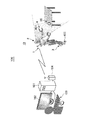
図1を参照して、本発明によるデータ伝送システム100は、遠隔操作端末101及びロボット10を具備する。ロボット10は、遠隔操作端末101からの指示(制御信号)に応じて移動、又は、後述する腕部4(マニピュレータ)の動作が制御される。例えば、ロボット10は、遠隔操作端末101からの指示により、「目標物90近傍まで移動し、目標物90を現在位置から他の位置に移動する」というオペレーションを実行する。この際、ロボット10は、3次元センサ2によって取得した周辺領域の点群データ20を遠隔操作端末101に送信する。ユーザは、点群データ20に基づいて作成されたロボット10の周辺における表面形状画像を確認しながら、遠隔操作端末101を操作することにより、ロボット10に次の動作を指示する。
Referring to FIG. 1, a
以下、図1及び図2を参照して、データ伝送システム100の構成の詳細を説明する。
Hereinafter, the configuration of the
遠隔操作端末101は、出力装置102、入力装置103、伝送装置104に接続される。遠隔操作端末101はコンピュータ装置に例示され、図示しないCPU及び記憶装置を具備する。遠隔操作端末101は、ロボット10の動作を制御するとともに、ロボット10から送信される点群データ20に基づいて計測対象の表面形状を画像化し、出力装置102に視認可能に出力する。遠隔操作端末101の構成の詳細は後述する。出力装置102は、モニタやプリンタに例示され、遠隔操作端末101から出力される画像情報を視認可能に出力する。入力装置103は、キーボード、タッチパネル、マウス、又はジョイスティック等に例示され、ユーザによって操作されることで各種情報を遠隔操作端末101に入力するインタフェース装置である。伝送装置104は、遠隔操作端末101とロボット10(伝送装置1)との間のデータや信号の伝送を制御する通信インタフェース装置である。詳細には、伝送装置104は、無線回線又は有線回線のいずれか、又は両方の回線により、ロボット10に搭載された伝送装置1との間に伝送路を構築し、遠隔操作端末101とロボット10との間のデータ伝送を制御する。
The
尚、遠隔操作端末101、出力装置102、入力装置103、伝送装置104は、図1に示すように、それぞれ個別の装置として設けられてもよいが、全て又はいずれかが一体として設けられてもよい。例えば、出力装置102及び入力装置103を一体とした形態は、タッチパネルにより実現できる。又、遠隔操作端末101と伝送装置104を一体とした形態は、通信機能付きのコンピュータ装置によって実現できる。更に、遠隔操作端末101、出力装置102、入力装置103、伝送装置104の全てが搭載された形態として、タッチパネル式の携帯電話(俗にスマートフォンと称す)や通信機能付きのPDA(Personal Digital Assistants)によって実現できる。
The
ロボット10は、伝送装置1、3次元センサ2、脚部3、腕部4を備える。ロボット10は、3次元センサ2によって計測した点群データ20のデータ量を所定のアルゴリズムに従って削減してから遠隔操作端末101に転送するデータ伝送装置として機能する。
The
伝送装置1は、ロボット10と遠隔操作端末101との間のデータや信号の伝送を制御するインタフェース装置である。詳細には、伝送装置1は、無線回線又は有線回線のいずれか、又は両方の回線により、遠隔操作端末101に接続された伝送装置104との間に伝送路を構築し、ロボット10と遠隔操作端末101との間のデータ伝送を制御する。
The
3次元センサ2は、レーザスキャナやステレオカメラに例示され、ロボット10周辺における計測対象物の表面の3次元位置座標を点群データ20(ポイントクラウドとも称す)として取得する。例えば、3次元センサ2として利用し得るレーザスキャナは、三角法方式、タイム・オブ・フライト方式、位相差方式(フェイズ・シフト)のいずれかの方式によって点群データ20を計測する。
The three-
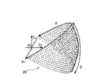
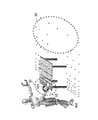
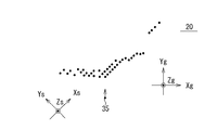
図2を参照して、3次元センサ2による点群データ20の計測範囲(走査範囲)の一例を説明する。ここで、3次元センサ2の計測位置を原点Osとし、計測した点群データ20の座標系を(Xs,Ys,Zs)とする。3次元センサ2は、レーザを、その照射角が原点Osを中心に方位角θ、仰俯角φの範囲で走査し、この範囲内の計測対象物からの反射光に基づいて、当該対象物の表面の3次元座標を点群データ20として計測する。ロボット10は、脚部3によって移動し複数の位置において点群データ20の計測を行い、計測した点群データ20をマッチング合成することで、所望の範囲の点群データ20を取得することができる。
An example of the measurement range (scanning range) of the
図1を参照して、脚部3は、後述するアクチュエータ16によって駆動され、ロボット10を任意の位置に移動させる移動手段である。本実施例では脚部3として関節及びリンクを有する脚を一例に説明するが、モータやエンジンによって回転する回転体(例えば車輪)が脚部3としてロボット10に搭載されてもよい。脚部3における脚の数、形状、関節数(リンク数)は、図示した数や形状に限定されず任意に設定できる。腕部4は、後述するアクチュエータ16によって駆動され、関節、リンク及びエンドエフェクタ401を有するマニピュレータ(アームとも称す)に例示される。エンドエフェクタ401は、通常、腕部4の先端に設けられ、対象物に対し物理的な作用(力学的作用、電磁気的作用、熱力学的作用)を与える機構を有することが好ましい。具体的には、エンドエフェクタ401は、対象物を把持、塗装、溶接、電磁気的センサ、各種計測機器等に例示される。本一例における腕部4には、対象物を把持(ハンドリング)するロボットハンドがエンドエフェクタ401として設けられている。腕部4における腕の数、形状、関節数(リンク数)、エンドエフェクタ401の構造は、図示した数や形状に限定されず任意に設定できる。
With reference to FIG. 1, the
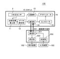
図3を参照して、本発明による遠隔操作端末101及びロボット10の構成の詳細を説明する。遠隔操作端末101では、図示しない記憶装置に格納されたプログラムをCPUが実行することにより、通信部201、表示部202、及び制御部203の各機能が実現される。通信部201、表示部202、及び制御部203の各機能は、ハードウェアのみ、又はソフトウェアとハードウェアの連携によって実現されても構わない。
With reference to FIG. 3, the details of the configuration of the
通信部201は、図1に示す伝送装置104を制御してロボット10における伝送装置1との間の通信を制御する。詳細には、通信部201は、制御部203からの制御信号を、伝送装置104を介してロボット10における伝送装置1に転送する。あるいは、ロボット10から転送された点群データ20を表示部202に出力する。表示部202は、出力装置102に表示させる画像情報を生成する。詳細には、表示部202は、通信部201から入力された点群データ20を利用して、計測対象物の表面形状を表示するための画像情報を作成し、出力装置102に出力する。例えば、表示部202は、点群データ20に対してエッジ検出、ノイズ除去による平滑化、法線抽出等の処理を経て、計測対象物の表面形状を表示するための画像情報を算出する。制御部203は、入力装置103からの入力信号に応じた制御信号を生成し、通信部201に出力する。ロボット10は、制御部203から出力された制御信号に応じて、例えば、脚部3や腕部4の運動や、点群データ20の取得動作が制御される。
The
ロボット10は、図示しないCPUや記憶装置を具備する。ロボット10では、図示しない記憶装置に格納されたプログラムをCPUが実行することにより、点群座標算出部11、データ選定部12、認識部13、通信部14、及びコントローラ15の各機能が実現される。点群座標算出部11、データ選定部12、認識部13、通信部14、及びコントローラ15の各機能は、ハードウェアのみ、又はソフトウェアとハードウェアの連携によって実現されても構わない。
The
点群座標算出部11は、3次元センサ2によって測定された、計測対象物と当該センサとの間の時間及び照射角度(反射角度)を用いて、測定点の3次元位置座標(X,Y,Z)を点群データ20として算出する。又、点群座標算出部11は、複数の位置において3次元センサ2よって得られた点群データ20をそれぞれの位置座標に応じてマッチングし、計測領域全体の点群データ20として抽出することが好ましい。点群座標算出部11によって算出された点群データ20は、データ選定部12に出力される。ここで、ロボット10は、3次元センサ2の他に、ロボット周辺の地形や対象物の形状の視認性を高めるための色情報(RGB)を取得するCCDカメラを搭載しても構わない。この場合、点群座標算出部11は、点群データ20と色情報とを合成(カラーマッチング)しても構わない。しかし、遠隔操作端末101へのデータ伝送量を低減するため、あるいは、ロボット10における計算量を低減するため、点群データ20と色情報は異なるタイミングで遠隔操作端末101に送信され、遠隔操作端末101においてカラーマッチングされてもよい。
The point group coordinate
データ選定部12は、点群座標算出部11によって得られた点群データ20から、遠隔操作端末101に転送する点群データ20の選定を行う。この際、データ選定部12は、所定の領域を設定し、当該領域における転送データのデータ量の上限を決めることが好ましい。
The
データ選定部12は、点群座標算出部11から取得した点群データ20が分布する仮想空間上にグリッド30を配置し、グリッド30内に登録される点群データ20の数を所定のアルゴリズムに従って削減する(選定処理)。データ選定部12は、グリッド30内に登録された点群データ20を転送対象の点群データ20として通信部14に出力する。データ選定部12は、グリッド30に登録した転送対象の点群データ20を、他の点群データ20に優先して先に転送する点群データ20として選定してもよい。この場合、選定処理において選定されなかった点群データ20を転送の優先度が低いデータとして通信部14に出力してもよい。データ選定部12によって選定された点群データ20や、選定される前の点群データ20は、図示しない記憶装置に記録されることが好ましい。データ選定部12におけるデータ選定処理動作の詳細は後述する。
The
又、データ選定部12は、所定の領域内の点群データ20を解析し、解析結果に応じたデータを転送対象データとして選定してもよい。点群データ20の解析結果に応じた転送対象データの選定方法の詳細は後述する。
Further, the
データ選定部12は、点群座標算出部11から取得した点群データ20の全て(選定前の点群データ20)を、認識部13に出力することが好ましい。ただし、データ選定部12は、転送対象データとして選定した点群データ20を認識部13に出力しても構わない。
The
認識部13は、点群データ20を解析し、3次元センサ2によって計測された領域(解析対象の点群データ20が分布する領域)における計測対象物の表面形状を割出し、計測対象物の表面形状をコントローラ15が認識可能な情報として出力する。この情報は、図示しない記憶装置に記録されることが好ましい。ここで得られる表面形状の情報は、例えば、計測領域内の周辺地形や目標物90の詳細な位置座標を示す情報を含む。
The recognizing
コントローラ15は、通信部14を介して遠隔操作端末101から入力された制御信号に基づいた動作指令信号によりアクチュエータ16の動作を制御する。詳細には、コントローラ15は、脚部3や腕部4を所望の位置に移動させるための制御信号(例えば、目標位置や目標姿勢に関する情報)を遠隔操作端末101から受信する。コントローラ15は、制御信号に基づき、脚部3や腕部4が遠隔操作端末101から指示された位置及び姿勢となるようにアクチュエータ16を制御する。この際、認識部13から出力された計測対象物の表面座標や、脚部3や腕部4におけるリンクやエンドエフェクタ401、402の位置座標を利用して、アクチュエータ16の動作量や動作方向を補正することが好ましい。
The
コントローラ15は、認識部13から出力された計測対象物の表面座標や、脚部3や腕部4におけるリンクやエンドエフェクタ401、402の位置座標を利用して、自律的にアクチュエータ16の動作量や動作方向を決定し、ロボット10の動作を制御してもよい。この際、コントローラ15は、動作精度の向上や移動経路の詳細な解析を行うため、転送対象として選定された点群データ20ではなく、認識部13において算出された詳細な表面形状の情報を利用することが好ましい。
The
アクチュエータ16は、サーボモータ、動力シリンダ、リニアアクチュエータ、ラバーアクチュエータ等に例示され、コントローラ15からの動作指令信号に応じて脚部3や腕部4の機械的挙動を制御する。アクチュエータ16は、脚部3や腕部4に対して間接的に駆動してもよいし、直接的に駆動してもよい。すなわち、アクチュエータ16と脚部3又は腕部4は異なる構成でもよいが、脚部3や腕部4の一部(例えば関節部)に搭載されてもよい。又、脚部3が車輪に例示される回転体である場合、アクチュエータ16としてモータやエンジンが適用される。
The actuator 16 is exemplified by a servo motor, a power cylinder, a linear actuator, a rubber actuator, and the like, and controls the mechanical behavior of the
(転送データ量削減方法)
図4から図17を参照して、本発明によるデータ伝送システム100における転送データ量の削減方法の詳細を説明する。先ず図4から図6を参照して、本発明によるデータ量削減方法の基本形態を説明する。
(Transfer data volume reduction method)
The details of the method for reducing the amount of transferred data in the
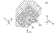
図4は、本発明に係るロボット10によって取得される点群データ20と計測対象物の概念図である。図4を参照して、本願発明に係るロボット10は、3次元センサ2によって計測対象物の点群データ20を取得する。計測対象物は、3次元センサ2による走査範囲にあるレーザ光を反射する要素であり、走査範囲内における周辺地形や目標物90を含む。複数の位置において計測された点群データ20を合成して広範囲の点群データ20を取得する場合、点群データ20は直交座標系(Xs,Ys,Zs)で示されることが好ましい。例えば、図2に示すように測定点Osにおいて計測された点群データ20が極座標で示される場合、直交座標系(Xs,Ys,Zs)に変更されることが好ましい。又、点群データ20が属するスキャン座標系(Xs,Ys,Zs)は、ロボット10、脚部3及び腕部4の位置座標と同じ絶対座標系であることが好ましい。
FIG. 4 is a conceptual diagram of the
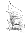
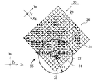
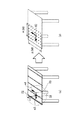
図5は、本発明に係るロボット10によって取得される点群データ20に対して配置されるグリッド30の一例を示す図である。図5を参照して、グリッド30は、仮想視線の方向Yg(以下、視線方向Ygと称す)、及び視線方向Ygに直交する方向Xg、Zgに延びる直線によって囲まれた複数のセル31(1,1,1)〜(Xl,Ym,Zn)によって形成される(l、m、nは2以上の自然数)。グリッド30の視線方向Ygは、点群データ20のスキャン座標系(Xs、Ys、Zs)とは独立して任意に設定し得る。又、グリッド30の向き(視線方向Yg)や、セル31の大きさ、数、位置、あるいはグリッド30全体の大きさは、遠隔操作端末101によって設定されることが好ましいが、ロボット10に予め設定されていても構わない。
FIG. 5 is a diagram showing an example of the
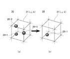
本発明によるロボット10は、グリッド30を利用したフィルタリングによって転送対象となる点群データ20のデータ量を削減し、削減後の点群データ20を遠隔操作端末101に転送する。例えば、ロボット10(データ選定部12)は、セル31内の点群データの数を所定の値に制限し、所定数を越える点群データ20を転送対象から除外、又は転送順の優先度を低くする。これにより、近接した複数の点群データ20の転送を所定数以内に制限できる。図6は、本発明によるグリッド30を利用した転送データの削減方法の一例を示す図である。図6を参照して、セル31内に転送データとして登録される点群データ数の上限を1つとしたときの転送データの削減方法について説明する。図6(a)に示されるように、仮想的に配置されたセル31(i,j,k)内に3つの点群データ20−1、20−2、20−3が含まれている場合、データ選定部12は、図6(b)に示すように、点群データ20−1のみを転送対象の点群データとしてセル31(i,j,k)内に登録し、他の点群データ20−2、20−3を転送対象から除外する(登録しない)(ただし、1≦i≦l(エル)、1≦j≦m、1≦k≦m)。ここで、セル31のサイズが1cmである場合、1cm四方に複数の点群データの1つを転送対象とし、他の点群データを転送対象から除外することができる。
The
尚、転送対象から除外された点群データ20−2、20−3は、先に選定された点群データ20−1の転送後に遠隔操作端末101に転送されるデータとして選定(登録)されても構わない。この場合、データ量の多い点群データ20を所定のデータ量毎に分割して遠隔操作端末101に転送することが可能となる。
The point cloud data 20-2 and 20-3 excluded from the transfer target are selected (registered) as data to be transferred to the
セル31内において転送対象として選定(登録)される順番は、任意に設定し得る。例えば、3次元センサ2の走査順に選定される。この場合、セル31内において3次元センサ2の走査方向の上流側の点群データ20が優先して転送対象として選定される。具体的には、点群データ20−1、20−2、20―3の順で計測され、転送対象の上限が2の場合、点群データ20−1、20−2が転送対象として選定される。
The order selected (registered) as a transfer target in the
以上のように、本発明によるデータ伝送システム100では、視線方向Ygを基準としたグリッド30を利用して、遠隔操作端末101へ転送されるデータ量を削減することができる。尚、グリッド30(セル31)の形状は立方体や直方体に限らず多面体でも構わない。又、セル31の大きさは、グリッド30内で均一ではなく場所に応じて異なる大きさでも構わない。セル31のサイズは、所定の領域内のセル31に対し八分木法を適用することで変更できる。この場合、計測対象のエッジ付近のセルサイズは小さく、エッジから離れた領域のセルサイズは大きく設定することができる。あるいは、後述するように、指定した領域や、重要点の近傍領域におけるセル31のサイズを他のセル31よりも小さくしてもよい。更に、グリッド30は視線方向Ygを基準として配置されることが好ましいが、他の方向を基準に配置されても構わない。
As described above, in the
第1の実施の形態
図7から図14を参照して、データ伝送システム100における転送データの削減方法の第1の実施の形態について説明する。第1実施の形態では、セル31内における点群データの転送率を、セル31の位置によって変化させている。すなわち、セル31の位置によって、点群データ20が大きく間引かれる領域と、小さく間引かれるセル領域が設定される。この結果、データ転送量を削減しながら、遠隔操作に影響する重要な領域を詳細に表示させることが可能となる。ここで、セル31における点群データ20の転送率とは、セル31内の点群データの数を等しくしたときの、セル31内における全ての点群データのデータ量に対する、転送対象として選定されたデータ(点群データとは限らない)のデータ量の割合を示す。すなわち、転送率とは、セル31内の点群データの総データ量に対する、転送データのデータ量の割合をセル毎に規格化した値を示す。
First Embodiment A first embodiment of a method for reducing transfer data in the
図7は、第1の実施の形態における転送データの削減方法の一例を示す図である。図7を参照して、本実施の形態では、重要点32から所定の距離の範囲によって示される領域33(第1領域とも称す)内における転送データの転送率が他の領域34(第2領域とも称す)に比べて大きくなるように設定される。転送データの転送率が大きい領域33を決める重要点32は、オペレーション精度を向上させるため、エンドエフェクタ401(手先)やエンドエフェクタ402(足先)における任意の点(又はその近傍の点)が設定されることが好ましい。例えば、腕部4のエンドエフェクタ401における所定の位置座標を重要点32に設定することで、ロボット10が把持している、あるいは把持を予定している目標物90やエンドエフェクタ401の周辺の領域についての詳細な状況を遠隔操作端末101に送信可能となる。あるいは、脚部3のエンドエフェクタ402における所定の座標を重要点32に設定することで、ロボット10に対する歩行制御を詳細に指示することが可能となる。又、他の領域については、転送率を小さくすることで転送データの総量を低減することが可能となる。
FIG. 7 is a diagram illustrating an example of a transfer data reduction method according to the first embodiment. Referring to FIG. 7, in the present embodiment, the transfer rate of transfer data in an area 33 (also referred to as a first area) indicated by a predetermined distance from
領域33は、重要点32を基準に決められれば、どのような形状でもよく、例えば重要点32からの距離が一定の範囲が好適である。転送データの転送率を小さくする領域34は、点群データ20が分布する領域において領域33以外の領域が好適に設定される。又、領域34は、重要点32からの距離に応じて段階的に転送データの転送率が小さくなってもよい。例えば、点群データ20が分布する領域を複数の領域に分割し、それぞれ重要点32からの距離に応じて(例えば比例して)転送データの転送率を小さくしてもよい。更に、領域33、34は複数設定されても構わない。この場合、それぞれが包含するセル31に対して転送データとして登録される上限や、転送率は任意に設定され得る。又、領域33、34を決める条件は上述の方法に限らず任意に設定できる。例えば、所定の座標条件の複数のセル31を領域33、他の座標条件の複数のセル31を領域34としてもよい。重要点32、領域33、領域34のそれぞれは、遠隔操作端末101から指定することができる。又、ロボット10が、遠隔操作端末101によって指定された重要点32に基づいて、領域33、領域34を自動計算してもよい。この場合、領域33、34を決めるための重要点32からの距離等のパラメータは、予めロボット10に設定されていることが好ましい。
The
領域33、34毎に設定される点群データ20の転送率は、セル31のサイズを変更することや、セル31内に転送対象として登録される点群データの上限を変更することで可能となる。図8から図14を参照して、グリッド30を利用した転送データの転送率の変更例を説明する。実際には3次元座標である点群データ20が転送対象から除外されるが、以下では、説明の簡単化のため点群データ20及びグリッド30を2次元的に表示して説明する。図8は、本発明に係るロボット10によって計測された点群データ20の一例を示す図である。
The transfer rate of the
先ず、図9に示すように、点群データ20が分布している仮想空間上に、グリッド30が配置される。この際、仮想視点35、グリッド30の配置位置や形状、視線方向Yg、セル31の大きさ(グリッド間隔)は、遠隔操作端末101によって指定されることが好ましい。尚、仮想視点35、グリッド30の配置位置や形状、視線方向Yg、セル31の大きさ(グリッド間隔)、数、配置のいずれかは、予めロボット10に設定され、これを利用してグリッド30が配置されても構わない。
First, as shown in FIG. 9, a
図10に示す一例では、図9に示すグリッド30において、重要点32周辺の領域33のグリッドサイズ(セル31のサイズ)が他の領域34よりも小さくなるように設定される。例えば、重要点32を中心に半径r1の領域33におけるセル31−1のサイズが、他の領域34のセル31−2のサイズの半分に設定される。ここで、全てのセル31内の点群データ20の上限を等しい値(例えば1つ)に制限した場合、セルサイズの小さな領域33における点群データ20の転送率は、他の領域34よりも大きくなる。換言すると、セルサイズの大きな領域34において転送対象として除外される点群データ20は、領域33よりも多くなる。これにより、領域33において転送対象となる点群データ20のデータ密度は、他の領域34における転送対象データのデータ密度よりも高くなる。
In the example shown in FIG. 10, in the
又、図11に示すように、領域33と領域34のセル31のサイズを変更せず(等しくし)、セル31内のデータ数の上限を領域(場所)に応じて変更することで、点群データの転送率を変更してもよい。図11に示す一例では、重要点32を中心に半径r1の領域33におけるセル31−1における点群データ20の転送率を100%(転送対象となる点群データ数の上限なし)とし、他の領域34のセル31−2の上限を1としている。このような方法によっても、領域33における点群データ20の転送率を他の領域34よりも大きくすることができ、領域33において転送対象となる点群データ20のデータ密度を、他の領域34における転送対象データのデータ密度よりも高くすることができる。
Also, as shown in FIG. 11, the size of the
尚、図10及び図11に示すように、グリッド30が配置されていない領域における点群データ20は、全て転送対象から除外(又は送信順の優先度が低く設定)されることが好ましい。
As shown in FIGS. 10 and 11, it is preferable that all
以上のように、本実施の形態におけるデータ伝送システム100では、領域33、34毎にセル31内の点群データの上限が決められるため、所定の位置における点群データ20の粗密を任意に変更しながら、データ通信量を低減することができる。
As described above, in the
図12は、図10又は図11に示す方法により転送対象として選定された点群データ20を示す図である。図12に示すように、領域33、34における転送データに密度差が生じるため、遠隔操作端末101は、エンドエフェクタ401周辺の領域については詳細に、その他の領域は簡略化された画像を得ることが可能となる。
FIG. 12 is a diagram showing the
図10から図12に示す一例では、重要点32によって決まる領域33のデータ転送率を大きくする方法について説明したが、これに限らず、仮想視点35や視線方向Ygに応じて、セル31において転送対象とする点群データの上限や、転送率を決めてもよい。
In the example shown in FIGS. 10 to 12, the method of increasing the data transfer rate of the
以下、図9、図13及び図14を参照して、仮想視点35や視線方向Ygに応じて転送対象データを選定する方法について具体例を説明する。
Hereinafter, a specific example of a method of selecting transfer target data according to the
先ず、図9に示すように、点群データ20が分布している仮想空間上に、グリッド30が配置される。この際、仮想視点35、グリッド30の配置位置や形状、視線方向Yg、セル31の大きさ(グリッド間隔)、数、又は位置が、遠隔操作端末101によって指定される。
First, as shown in FIG. 9, a
図13を参照して、仮想視点35側から視線方向Ygに見える点群データ20が位置するセル31−3(第1領域とも称す)内の点群データ20のみが転送対象として登録され、他のセル31−4(第2領域とも称す)内の点群データが転送対象から除外される。詳細には、視線方向Ygのセル列(セル31(i、1、k)〜セル31(i、Ym、k))において、点群データ20を包含するセル31のうち、仮想視点35側に最も近いセル31が、視線方向Ygについてh番目のセル31−3(i、h、k)である場合、セル31−3(i、h、k)の点群データ20が転送対象として登録され、他のセル31−4(i、h+1、k)〜セル31−4(i、h+Ym、k)の点群データ20は、転送対象から除外される(ただし、1≦h≦Ym−1)。又、点群データ20を包含するセル31のうち仮想視点35側に最も近いセル31−3が、視線方向Ygのセル列(セル31(i、1、k)〜セル31(i、Ym、k))においてYm番目のセル31である場合、セル31−3(i、Ym、k)の点群データ20が転送対象として登録される。
Referring to FIG. 13, only the
図14は、図13に示す方法により転送データ量が削減され、転送対象として選定された点群データ20を示す図である。図14に示すように、仮想視点35から視線方向Ygを見たときの表面形状のみが遠隔操作端末101への転送対象となり、その視線方向Yg奥側の点群データ20は転送対象から除外される。
FIG. 14 is a diagram showing the
本実施例では、仮想視点35側から視線方向Ygを見たときの表面形状のみが、遠隔操作端末101に転送されるため、遠隔操作端末101は、図14に示すように奥行方向に重なる点群データ20を省いた見易い画像を表示することができる。又、転送データから奥行き方向に重なる点群データ20の全てが除外されるため、図10や図11に示す方法に比べてデータ通信量を更に削減することができる。本実施例では、仮想視点35側から見た奥側のセル31−4の点群データ20の全てが転送対象から除外されたが、これに限らず、セル31−4内の点群データ20のうち、所定の数の点群データ20は、転送対象として登録されても構わない。換言すると、本一例では、所定の領域(セル31−4)の上限が0に設定されているが、この上限は任意に設定し得る。この場合、上述の方法によって転送データが選定されることが好ましい。更に、転送データを更に削減するため、セル31−3に対し、上述の方法により転送データが選定されても構わない。ただし、セル31−3内の点群データ20の上限は、セル31−2の上限よりも多くなるように設定される。
In this embodiment, since only the surface shape when viewing the line-of-sight direction Yg from the
点群データの転送率を小さくする領域34やセル31−4、転送率を大きくする(削減しない場合も含む)領域33やセル31−3の設定方法は、上述の例に限らず、セル位置を規定する所定の条件に応じて決めてもよい。例えば、視線方向Ygにおいて仮想視点35から所定の距離よりも遠方の領域を領域34に設定し、近い領域を領域33に設定してもよい。あるいは、セル位置(座標)を指定する条件に応じて転送率の大きなセル31と転送率の小さなセル31が設定されてもよい。一例として、Xg座標、Yg座標、Zg座標が偶数のセル31を転送率の大きなセル31、奇数のセル31を転送率の小さなセル31として設定される。ここで、領域33、34を決定する所定の距離やセル位置を指定する座標条件は、ロボット10に予め設定されていてもよいし、遠隔操作端末101から指定されてもよい。
The setting method of the
第2の実施の形態
第2の実施の形態におけるロボット10は、点群データ20から予測された計測対象物の形状に応じて遠隔操作端末101に転送するデータを決定する。第2の実施の形態における遠隔操作端末101の表示部202は、ロボット10から転送されたデータに基づいて点群データを生成し、これを用いて計測対象物の表面形状を表示する。以下、データ伝送システム100における転送データの削減方法の第2の実施の形態について説明する。
Second Embodiment The
本実施の形態におけるデータ伝送システム100は、「計測対象物の局所的な形状」に応じて転送データの削減率を変更する。ここで、「計測対象物の局所的な形状」とは、所定の範囲内における点群データに対する主成分分析によって得られる3つの固有値の大きさによって分類できる。ここで固有値を大きい順にd1、d2、d3とすると、計測対象物の局所的な形状を、下記のパタン1からパタン5のように分類できる。
The
d1≒d2≒d3≒0 : 0次元的な広がりを持つ点構造・・・パタン1
d1>>d2≒d3≒0 : 1次元的な広がりを持つ線状構造・・・パタン2
d1>d2>>d3≒0 : 2次元的な広がりを持つ平面構造・・・パタン3
d1>d2>d3>>0 : 3次元的な広がりを持つ立体構造・・・パタン4
その他:パタン5
d1≈d2≈d3≈0: Point structure having a zero-dimensional spread:
d1 >> d2≈d3≈0: linear structure having a one-
d1> d2 >> d3≈0: planar structure having a two-dimensional extent:
d1>d2> d3 >> 0: Three-dimensional structure having a three-dimensional spread:
Other: Pattern 5
図15から図17を参照して、計測対象物の局所的な形状の分類方法及び転送データ量の削減方法について、詳細に説明する。 With reference to FIGS. 15 to 17, a method for classifying a local shape of a measurement object and a method for reducing the amount of transferred data will be described in detail.
図15(a)、図16(a)、図17を参照して、ロボット10のデータ選定部12は、計測された点群データ20の1つを基準点51として設定し、基準点51に応じた範囲を解析領域52として設定する。解析領域52は、例えば基準点51を中心とした半径r2の球形領域が好適に設定される。基準点51は少なくとも1つランダムに決めてよい。又、解析領域52を決める基準点51からの距離(例えば半径r2)は、固定値が設定されることが好ましい。基準点51が複数設定される場合、隣接する基準点51の間隔は、解析領域52が重ならない長さ(例えば半径r2以上)であることが好ましい。
With reference to FIGS. 15A, 16 A, and 17, the
データ選定部12は、解析領域52内における点群データ20(位置座標)に対して主成分分析し、固有値d1、d2、d3及びこれらに対応する固有ベクトルe1、e2、e3を求める。詳細には、解析領域52内の点群データ20が示す位置座標から求められた共分散行列を固有値分解し、固有値d1、d2、d3及びこれらに対応する固有ベクトルe1、e2、e3が求められる。ここで、データ選定部12は、固有値d1、d2、d3の大きさに応じて解析領域52内の形状をパタン1〜パタン5のいずれかに分類する。データ選定部12は、分類したパタンに応じて転送するデータを選定する。このとき、パタン2、3に分類された場合、データ選定部12は、解析領域52内の点群データ20に替えて、解析領域52に対する解析結果を形状再現データとして遠隔操作端末101に送信する。遠隔操作端末101は、形状再現データに基づいた範囲内に所定の間隔で分布する点群データを配置し、計測対象形状画像を生成、表示する。
The
点群データ20がほぼ1点に集まっている場合、すなわち点群データ20が0次元的な広がりを持つ構造を示す場合、固有値は、d1≒d2≒d3≒0となりパタン1に分類される。すなわち、固有値d1、d2、d3の全てが所定の第1の値より小さく0に近似する場合(0も含む)、パタン1に分類される。例えば、点状の物体や点数が1点しかない場合、パタン1に分類される。データ選定部12は、パタン1に分類された解析領域52内の点群データ20の全てを転送対象から除外する(転送率は0%)。すなわち、パタン1に分類された解析領域52内の点群データ20は全て遠隔操作端末101に転送されない。この領域については、ロボット10の行動に影響する地形や障害物がないと判断できるため、遠隔操作端末101に点群データ20を送信する必要はない。
When the
点群データ20が図15(a)に示されるように1次元的な広がりを持つ構造を示す場合、固有値は、d1>>d2≒d3≒0となりパタン2に分類される。すなわち、固有値d2、d3が所定の第2の値より小さく0に近似し(0も含む)、固有値d1の値が、d2及びd3に比べて所定の第3の値よりも大きい場合、パタン2に分類される。データ選定部12は、パタン2として分類された解析領域52内の点群データ20に替えて、形状再現データを遠隔操作端末101に対する転送対象として選定する。例えば、図15(a)を参照して、パタン2として分類された解析領域52内における点群データ20(3次元座標A1〜Ai)の平均座標60(3次元座標Aa)と、固有値d1に対応した固有ベクトルe1と、固有値d1が、形状再現データとして遠隔操作端末101に送信される。ここで平均座標60は、点群データ20の分布領域の中心座標を意味する。又、固有ベクトルe1は、点群データ20の分布範囲の広がる方向を意味し、固有値d1は、固有ベクトルe1方向における点群データ20の分布範囲の大きさを意味する。パタン2に分類された領域については、点群データの替わりにデータ量の小さな形状再現データが送信されるため、データ通信量を大きく削減することができる(転送率小)。
When the
図15(b)を参照して、遠隔操作端末101の表示部202は、平均座標60を中心に、固有ベクトルe1の方向に対し固有値d1に基づいた大きさだけ広がる領域を点群データの分布領域として設定し、当該分布領域に所定の間隔で配置した点群データを生成して表示する。例えば、表示部202は、固有ベクトルe1の方向に、平均座標60から固有値d1の±3倍の範囲(±3d1×固有ベクトルe1)の線状領域を点群データの分布領域とし、当該領域に所定の間隔で点群データを配置して表示する。ここで、再現される点群データの間隔は、予め設定されても、ユーザが操作する入力装置103によって指定されてもどちらでもよい。又、表示部202は、生成した点群データに基づいて、計測対象物の表面形状を生成して表示してもよい。
Referring to FIG. 15B, the
点群データ20が図16(a)に示されるように2次元的な広がりを持つ構造を示す場合、固有値は、d1>d2>>d3≒0となりパタン3に分類される。すなわち、固有値d3のみが所定の第4の値より小さく0に近似し(0も含む)、固有値d1、d2の値が、d3に比べて所定の第5の値よりも大きく、固有値d1の値がd2よりも大きい場合、パタン3に分類される。データ選定部12は、パタン3として分類された解析領域52内の点群データ20に替えて形状再現データを遠隔操作端末101に送信する。例えば、図16(a)を参照して、パタン3として分類された解析領域52内における点群データ20(3次元座標A1〜Ai)の平均座標60(3次元座標Aa)、固有値d1に対応した固有ベクトルe1、固有値d2に対応した固有ベクトルe2、固有値d1、d2が、形状再現データとして遠隔操作端末101に送信される。ここで平均座標60は、点群データ20の分布領域の中心座標を意味する。又、固有ベクトルe1、e2は、点群データ20の分布範囲の広がる方向を意味し、固有値d1は、固有ベクトルe1方向における点群データ20の分布範囲の大きさを意味し、固有値d2は、固有ベクトルe2方向における点群データ20の分布範囲の大きさを意味する。パタン3に分類された領域については、点群データの替わりにデータ量の小さな形状再現データが送信されるため、データ通信量を大きく削減することができる(転送率小)。
When the
図16(b)を参照して、遠隔操作端末101の表示部202は、平均座標60を中心に、固有ベクトルe1の方向に対し固有値d1に基づいた大きさだけ広がるとともに、固有ベクトルe2の方向に対し固有値d2に基づいた大きさだけ広がる領域を点群データの分布領域として設定し、当該分布領域に所定の間隔で配置した点群データを生成して表示する。例えば、表示部202は、固有ベクトルe1の方向に、平均座標60から固有値d1の±3倍の範囲(±3d1×固有ベクトルe1)と、固有ベクトルe2の方向に、平均座標60から固有値d1の±3倍の範囲(±3d1×固有ベクトルe1)に囲まれた平面領域を点群データの分布領域とし、当該領域に所定の間隔で点群データを配置して表示する。ここで、点群データの間隔は、予め設定されても、ユーザが操作する入力装置103によって指定されてもどちらでもよい。又、表示部202は、生成した点群データに基づいて、計測対象物の表面形状を生成して表示してもよい。
Referring to FIG. 16 (b), the
図17を参照して、点群データ20が3次元的な広がりを持つ構造を示す場合、固有値は、d1>d2>d3>>0となりパタン4に分類される。すなわち、固有値d1、d2、d3の全てが0に比べて所定の第6の値よりも大きく、固有値d3よりもd2、固有値d2よりもd1が大きい場合、パタン3に分類される。遠隔操作端末101を操作するユーザにとって、立体的な形状を詳細に確認する要求が高いため、パタン4に分類された解析領域52内の点群データ20については、全て転送対象として選定されることが好ましい(転送率100%)。あるいは、パタン4に分類された解析領域52内の点群データ20については、上述のグリッド30を利用したデータ選定方法が採用されてもよい。
Referring to FIG. 17, when the
固有値d1、d2、d3が、パタン1〜パタン4のいずれにも該当しない値を示す場合、パタン5に分類される。パタン5に分類された領域(図示なし)内の点群データ20は、上述のグリッド30を利用したデータ選定方法によって転送データの選定が行われること
が好ましい。あるいは、パタン5に分類された領域内の点群データ20は、全て転送対象から除外されてもよい(転送率0%)。
When the eigenvalues d1, d2, and d3 indicate values that do not correspond to any of the
尚、パタン判定において固有値の大きさを比較するための基準値である第1〜第6の値は、点群データを取得する用途やセンサの測定精度に応じて任意に設定し得る。例えば、センサの測定精度に応じて、パタン判定に利用される第1〜第6の値を任意に設定される。具体的には、測定ばらつきが±1cmである場合、標準偏差3σが±1cm、固有値d3(σの2乗)が1/9cm2となる。この場合、測定ばらつきを考慮して平面上の凹凸を検出する場合、固有値d3が0に近似するか否かの判定基準(第4の値)は、1/9cm2よりも大きな値に設定する必要がある。例えば、測定ばらつきが±1cmのセンサにおいて、第4の値を1/5cm2とすることで、固有値d3が1/5cm2よりも小さい場合を0に近似と判定し、平面形状と判定できる。又、パタン判定に利用される第1〜第6の値を任意に設定することで任意の測定精度を実現することができる。例えば、固有値が0に近似するか否かを決める基準値(例えば第4の値)は、平面上の凹凸(立体物)をmm単位で計測する場合(精密測定)に比べ、m単位で計測する場合(非精密測定)の方が大きく設定される。 Note that the first to sixth values, which are reference values for comparing the magnitudes of the eigenvalues in the pattern determination, can be arbitrarily set according to the application for acquiring the point cloud data and the measurement accuracy of the sensor. For example, the first to sixth values used for pattern determination are arbitrarily set according to the measurement accuracy of the sensor. Specifically, when the measurement variation is ± 1 cm, the standard deviation 3σ is ± 1 cm, and the eigenvalue d3 (σ squared) is 1/9 cm 2 . In this case, when unevenness on a plane is detected in consideration of measurement variations, a criterion (fourth value) for determining whether or not the eigenvalue d3 is close to 0 is set to a value larger than 1/9 cm 2. There is a need. For example, in a sensor with a measurement variation of ± 1 cm, by setting the fourth value to 1/5 cm 2 , the case where the eigenvalue d3 is smaller than 1/5 cm 2 is determined to be approximate to 0, and the planar shape can be determined. Further, arbitrary measurement accuracy can be realized by arbitrarily setting the first to sixth values used for pattern determination. For example, the reference value (for example, the fourth value) that determines whether or not the eigenvalue approximates 0 is measured in units of m compared to the case of measuring unevenness on a plane (three-dimensional object) in units of mm (precision measurement). In the case of (non-precision measurement), it is set larger.
パタン2、パタン3と判定された場合、遠隔操作端末101において1次元又は2次元形状が再現できれば、形状再現データの形式は上述のものに限らない。例えば、パタン2と判定された場合(1次元形状として判定された場合)、線形状を定義できる少なくとも2つの点群データ20(例えば、固有ベクトルe1方向において固有値d1だけ離れた2点)が、転送対象として選定される。あるいは、パタン3と判定された場合(2次元形状として判定された場合)、平面形状を定義できる少なくとも3つの点群データ20(例えば、固有ベクトルe1方向において固有値d1だけ離れた2点、及び、当該2点の少なくとも一方について、固有ベクトルe2方向において固有値d2だけ離れた1点)が、転送対象として選定される。この場合も、ロボット10と遠隔操作端末101との間の通信量を大きく削減することができる。
If it is determined as
本実施の形態では、領域毎に分類されたパタンに応じて、当該領域における転送データが選定されるとともに、そのデータ量の上限も決まる。例えば、ある領域に対して形状再現データが転送対象データとして設定された場合、当該領域に対するデータ量は、形状再現データのデータ量によって決まる。 In the present embodiment, the transfer data in the area is selected and the upper limit of the data amount is determined according to the pattern classified for each area. For example, when the shape reproduction data is set as transfer target data for a certain area, the data amount for the area is determined by the data amount of the shape reproduction data.
以上のように、第2の実施の形態におけるデータ転送方法によれば、遠隔操作端末101において計測対象物の表面形状を再現可能な形状再現データを、当該計測対象物の予想形状に応じて選定して遠隔操作端末101に送信する。形状再現データは、点群データ20よりも少ないデータ量であるため、点群データ20を送信する場合に比べデータ通信量を低減することができる。又、計測対象物の表面形状に応じたデータに基づいて点群データの分布及び対象物の形状を再現しているため、ロボット10に対する操作性に影響のない範囲内で当該ロボット10周辺の状況を把握することが可能となる。
As described above, according to the data transfer method in the second embodiment, the shape reproduction data capable of reproducing the surface shape of the measurement object in the
次に、ロボット10から、点群データ20又は計測対象物の表面形状を再現するためのデータを遠隔操作端末101に転送する方法について説明する。
Next, a method for transferring the
ロボット10は、上述した選定方法によって転送対象として選定されたデータのみならず、選定対象から除外したデータも遠隔操作端末101に送信してもよい。この場合、ロボット10は、転送対象として選定したデータを、選定対象から除外したデータよりも前に送信することが好ましい。すなわち、上述した転送対象を選定した方法によって遠隔操作端末101に送信するデータの送信順が設定されることが好ましい。詳細には、最初に計測された点群データ20から転送対象として選定されたデータを最優先に転送し、他のデータ(転送対象から除外されたデータ)については、その後に転送するように送信順が付与される。又、転送対象から除外された点群データに対して、更に上述の選定処理が行われ、送信順が決められてもよい。これにより、遠隔操作端末101に対して、重要度の高い点群データ20又は形状再現データが先に送信され、重要度の低いデータが順次送信されることとなる。遠隔操作端末101を操作するユーザは、ロボット10からデータ転送が開始されてから早い段階で、ロボット10を操作するために重要な情報(例えば手先周辺の状況)を得ることができるとともに、その後、重要度の低い情報により計測対象物の全体像を把握することができる。
The
又、ロボット10は、点群データ20の転送率の大きな領域33やセル31−3における転送対象の点群データ20を最優先に送信し、他の領域34やセル31−4における転送対象の点群データ20を、その後に送信してもよい。すなわち、点群データ20の転送率に応じて遠隔操作端末101に対する送信順が設定されることが好ましい。この際、転送対象から除外された点群データ20は、領域33、34やセル31−3、セル31−4において転送対象に設定された点群データ20よりも後に転送される。この場合も、遠隔操作端末101のユーザは、早い段階で重要な領域(例えば手先や、視線方向の手前側)における表面形状画像を視認することが可能となり、その後、計測対象物の全体像を把握することができる。尚、領域33、領域34内における点群データ20の送信順が設定できれば、領域33、34内の全ての点群データ20を送信しても構わない。
The
更に、ロボット10は、セル位置(座標)を指定する条件に応じて点群データ20の送信順を設定してもよい。例えば、Xg座標、Yg座標、Zg座標が4の倍数のセル31内の点群データ20を最優先に送信し、2の倍数で4の倍数を除くセル31内の点群データ20を次に送信し、奇数のセル31を最後に送信する。この場合、最初に空間分解能の粗い点群データ20(セル間隔が長いセル31内の点群データ)が送信され、その間に位置する細かい点群データ20(送信済みのセル31とセル31の間のセル内の点群データ20)が順次送信されることとなる。遠隔操作端末101のユーザは、空間分解能の粗いデータを受け取った段階で、計測対象物の大まかな形状を確認でき、時間の経過(逐次送信されるデータの受信)に伴い、詳細な状況を把握することができる。
Furthermore, the
以上のように、本発明によるデータ伝送システム100によれば、ロボット10の操作に必要最小限のデータを優先して送信し、遠隔操作端末101において画像化可能なため、ユーザは、通信環境が悪い場合や通信容量が小さい伝送路を使用した場合でも、ロボット周辺の状況を短時間で把握することができる。これにより、ロボット操作に要する時間を短縮化できる。又、段階的に送信されるデータにより、時間経過とともにより詳細な状況も把握することができる。
As described above, according to the
ロボット10は、転送用に選定した低密度の点群データ20(以下、低密度データと称す)の他、自律動作のため、3次元センサ2によって計測した高密度の点群データ20(以下、高密度データと称す)を利用できることが好ましい。すなわち、ロボット10は、用途に応じて低密度データと高密度の点群データ20の複数のデータを使い分けることが好ましい。人間は、低密度データ(例えば、点群データの最低間隔が1cm程度)によって作成された地図情報や表面形状を参照することでロボット10を操作することが可能である。一方、ロボット10の自律動作(例えば自律移動)のためには、衝突や転倒を防止するため、精度の高い地図情報や表面形状が必要となる。このため、ロボット10は、遠隔操作のためには低密度データを送信し、自律移動のためには、高密度データに基づいて生成した地図情報を利用することが好ましい。このように粗密データを使い分けることで、ロボット10の自律制御の精度を維持したまま、データ転送量を低減することが可能となる。
In addition to the low-density
又、人間は、形状の違いだけでなく、色の違いを用いた認識能力が高いため、遠隔操作用に利用される点群データには色情報が付加されていることが好ましい。このため、ロボット10は、色情報(RGB)を付加した点群データ20(Xs、Ys、Zs、R、G、B)、又は色情報(RGB)と点群データ(Xs、Ts、Zs)を遠隔操作端末101に送信することが好ましい。一方、座標データのみで制御精度を維持できることから、ロボット10の自律移動等の制御には色情報(RGB)を付加しない点群データ(Xs、Ys、Zs)が利用されることが好ましい。すなわち、ロボット10は、遠隔操作のためには色つきのデータを送信し、自律移動のためには、色なしのデータに基づいて生成した地図情報を利用することが好ましい。このように色情報の有無を使い分けることで、ロボット10の自律制御の精度を維持したまま、データ転送量を低減することが可能となる。
In addition, since human beings have high recognition ability using not only differences in shape but also differences in color, it is preferable that color information is added to point cloud data used for remote operation. For this reason, the
更に、ロボット10は、遠隔操作端末101との間の通信品質や通信容量に応じて、転送データの削減率を制御することが好ましい。例えば、ロボット10は、通信速度が低い場合は、転送データの削減量を大きく設定し、通信速度が高い場合は削減量を小さくする。あるいは、ロボット10と遠隔操作端末101間の通信量が、予め設定された通信容量を超える場合、転送データの削減量が大きくなるように設定される。ここで、通信品質は、ロボット10と遠隔操作端末101との間の伝送路における通信速度や伝搬環境(例えば受信強度)を示し、ロボット10又は遠隔操作端末101において測定される。ロボット10自身が通信品質の測定を行いこれに応じて転送率の設定・変更を行ってもよい。しかし、ロボット10の処理負荷の軽減や軽量化の観点から、通信品質の測定及びロボット10に対する転送率の設定・変更の制御は、遠隔操作端末101によって行われることが好ましい。
Furthermore, it is preferable that the
以上のように、本発明によれば、計測対象物の表面形状に関する情報を効率よく選定し、遠隔操作端末101に転送できる。このため、通信速度が低い、通信容量の上限が小さい、あるいは通信品質が劣悪な状況においても、少ないデータ通信量で、ロボット10を遠隔操作するが可能となる。又、遠隔操作に重要な影響を与える形状に関するデータを選択して早期に送信しているため、ユーザは迅速な判断が可能となり、ロボット10を使ったオペレーションを短時間で完遂することが可能となる。
As described above, according to the present invention, information related to the surface shape of the measurement target can be efficiently selected and transferred to the
以上、本発明の実施の形態を詳述してきたが、具体的な構成は上記実施の形態に限られるものではなく、本発明の要旨を逸脱しない範囲の変更があっても本発明に含まれる。上述した実施例及び実施の形態は、技術的な矛盾がない範囲内で組み合わせて実行できる。 The embodiment of the present invention has been described in detail above, but the specific configuration is not limited to the above-described embodiment, and changes within a scope not departing from the gist of the present invention are included in the present invention. . The above-described examples and embodiments can be combined and executed within a range where there is no technical contradiction.
1 :伝送装置
2 :3次元センサ
3 :脚部
4 :腕部
10 :ロボット
11 :点群座標算出部
12 :データ選定部
13 :認識部
14 :通信部
15 :コントローラ
16 :アクチュエータ
20 :点群データ
30 :グリッド
31 :セル
32 :重要点
100 :データ伝送システム
101 :遠隔操作端末
102 :出力装置
103 :入力装置
104 :伝送装置
201 :通信部
202 :表示部
203 :制御部
401、402 :エンドエフェクタ
DESCRIPTION OF SYMBOLS 1: Transmission apparatus 2: Three-dimensional sensor 3: Leg part 4: Arm part 10: Robot 11: Point group coordinate calculation part 12: Data selection part 13: Recognition part 14: Communication part 15: Controller 16: Actuator 20: Point group Data 30: Grid 31: Cell 32: Important point 100: Data transmission system 101: Remote operation terminal 102: Output device 103: Input device 104: Transmission device 201: Communication unit 202: Display unit 203:
Claims (35)
3次元座標を含む点群データを計測する3次元センサと、
前記点群データに基づいて転送対象データを選定するデータ選定部と、
前記転送対象データを前記遠隔操作端末に送信する通信部と
を具備し、
前記データ選定部は、所定の範囲の領域における転送対象データのデータ量の上限を決める
データ伝送装置。 An actuator whose operation is controlled according to a control signal from a remote operation terminal;
A three-dimensional sensor for measuring point cloud data including three-dimensional coordinates;
A data selection unit for selecting data to be transferred based on the point cloud data;
A communication unit for transmitting the transfer target data to the remote control terminal,
The data selection unit is a data transmission device that determines an upper limit of a data amount of data to be transferred in an area of a predetermined range.
前記データ選定部は、複数のセルを有する3次元グリッドを、計測された前記点群データの分布する領域に仮想的に配置し、前記複数のセルの各々に設定された上限以下の点群データを当該セル内の転送対象データとして選定する
データ伝送装置。 The data transmission device according to claim 1,
The data selection unit virtually arranges a three-dimensional grid having a plurality of cells in an area where the measured point cloud data is distributed, and the point cloud data below the upper limit set for each of the plurality of cells. A data transmission device that selects as data to be transferred in the cell.
前記データ選定部は、所定の範囲の第1領域内の点群データの転送率を、他の第2領域内の点群データの転送率よりも多く設定し、
前記転送率は、セル内の点群データのデータ量に対する、転送対象データのデータ量の割合を規格化した値を示す
データ伝送装置。 The data transmission device according to claim 2,
The data selection unit sets the transfer rate of point cloud data in the first area within a predetermined range to be higher than the transfer rate of point cloud data in the other second area,
The data transfer apparatus, wherein the transfer rate indicates a value obtained by standardizing a ratio of a data amount of transfer target data to a data amount of point cloud data in a cell.
前記第1領域内のセルの大きさは前記第2領域内のセルと等しく、
前記第1領域内のセル内の点群データの数の上限は、前記第2領域のセル内の点群データの上限よりも多く設定され、
前記データ選定部は、セル内の前記上限以下の点群データを転送対象データとして選定する
データ伝送装置。 The data transmission device according to claim 3, wherein
The size of the cells in the first region is equal to the cells in the second region;
The upper limit of the number of point cloud data in the cells in the first area is set more than the upper limit of the point cloud data in the cells of the second area,
The data selection unit is a data transmission device that selects point group data in the cell that is equal to or lower than the upper limit as transfer target data.
前記第1領域内のセルの大きさは、前記第2領域内のセルよりも小さく、
前記第1領域内のセル内の点群データの数の上限と、前記第2領域のセル内の点群データの上限は等しく設定され、
前記データ選定部は、セル内の前記上限以下の点群データを転送対象データとして選定する
データ伝送装置。 The data transmission device according to claim 3, wherein
The size of the cell in the first region is smaller than the cell in the second region,
The upper limit of the number of point cloud data in the cell in the first area and the upper limit of the point cloud data in the cell of the second area are set equal,
The data selection unit is a data transmission device that selects point group data in the cell that is equal to or lower than the upper limit as transfer target data.
前記第1領域は、前記アクチュエータによって駆動される腕部に設けられたエンドエフェクタの周辺領域を含む
データ伝送装置。 In the data transmission device according to any one of claims 3 to 5,
The first area includes a peripheral area of an end effector provided on an arm portion driven by the actuator.
前記第1領域は、前記遠隔操作端末によって指定される
データ伝送装置。 In the data transmission device according to any one of claims 3 to 5,
The first area is a data transmission apparatus specified by the remote operation terminal.
前記複数のセルの各々は、仮想視線の方向、及び当該方向に直交する方向に延びる直線によって囲まれたセルであって、
仮想視点側から前記仮想視線の方向に見える点群データが位置するセルが前記第1領域として設定され、
他のセルが第2領域として設定される
データ伝送装置。 The data transmission device according to claim 3, wherein
Each of the plurality of cells is a cell surrounded by a direction of a virtual line of sight and a straight line extending in a direction orthogonal to the direction,
A cell in which point cloud data that can be seen from the virtual viewpoint side in the direction of the virtual line of sight is located is set as the first region,
A data transmission apparatus in which other cells are set as the second area.
前記第2領域内の点群データの全ては転送対象データから除外される
データ伝送装置。 The data transmission device according to claim 8, wherein
A data transmission apparatus in which all of the point cloud data in the second area is excluded from transfer target data.
前記データ選定部は、所定の領域内における前記点群データに対する主成分分析結果に応じた値を、前記所定の領域内における転送対象データとして選定する
データ伝送装置。 The data transmission device according to claim 1,
The data selection device, wherein the data selection unit selects a value according to a principal component analysis result for the point cloud data in a predetermined area as transfer target data in the predetermined area.
前記主成分分析によって得られた固有値d1、d2、d3の値が、d1>>d2≒d3≒0の場合、
前記データ選定部は、固有値d1に対応した固有ベクトルe1、及び固有値d1を、前記所定の領域内における転送対象データとして選定する
データ伝送装置。 The data transmission apparatus according to claim 10, wherein
When the values of the eigenvalues d1, d2, and d3 obtained by the principal component analysis are d1 >> d2≈d3≈0,
The data selection unit is a data transmission device that selects an eigenvector e1 and an eigenvalue d1 corresponding to the eigenvalue d1 as transfer target data in the predetermined area.
前記主成分分析によって得られた固有値d1、d2、d3の値が、d1>d2>>d3≒0の場合、
前記データ選定部は、固有値d1に対応した固有ベクトルe1、固有値d1、固有値d2に対応した固有ベクトルe2、及び固有値d2を、前記所定の領域内における転送対象データとして選定する
データ伝送装置。 The data transmission device according to claim 10 or 11,
When the values of the eigenvalues d1, d2, and d3 obtained by the principal component analysis are d1> d2 >> d3≈0,
The data selection unit selects an eigenvector e1, an eigenvalue d1, an eigenvector e2 corresponding to an eigenvalue d2, and an eigenvalue d2 corresponding to the eigenvalue d1 as transfer target data in the predetermined area.
前記主成分分析によって得られた固有値d1、d2、d3の値が、d1>d2>d3>>0の場合、
前記データ選定部は、前記所定の領域内における点群データを転送対象データとして選定する
データ伝送装置。 The data transmission device according to any one of claims 10 to 12,
When the values of eigenvalues d1, d2, and d3 obtained by the principal component analysis are d1>d2> d3 >> 0,
The data selection unit is a data transmission device that selects point cloud data in the predetermined area as transfer target data.
前記主成分分析によって得られた固有値d1、d2、d3の値が、d1≒d2≒d3≒0の場合、
前記データ選定部は、前記所定の領域内における全ての点群データを転送対象から除外する
データ伝送装置。 The data transmission device according to any one of claims 10 to 13,
When the values of the eigenvalues d1, d2, and d3 obtained by the principal component analysis are d1≈d2≈d3≈0,
The data selection unit is a data transmission device that excludes all point cloud data in the predetermined area from transfer targets.
前記通信部は、前記遠隔操作端末に対し、前記転送対象データを送信した後に、前記計測された点群データから前記転送対象データを除くデータの少なくとも一部を送信する
データ伝送装置。 The data transmission device according to any one of claims 1 to 14,
The communication unit transmits at least a part of data excluding the transfer target data from the measured point cloud data after transmitting the transfer target data to the remote operation terminal.
前記計測された全ての点群データを利用して、前記アクチュエータを自律制御するコントローラを更に具備する
データ伝送装置。 The data transmission device according to any one of claims 1 to 15,
A data transmission device further comprising a controller for autonomously controlling the actuator using all the measured point cloud data.
前記通信部は、前記転送対象データとともに、計測された色情報を前記遠隔操作端末に送信する
データ伝送装置。 The data transmission device according to any one of claims 1 to 16,
The data communication device, wherein the communication unit transmits measured color information to the remote operation terminal together with the transfer target data.
前記遠隔操作端末と
を具備し、
前記遠隔操作端末は、前記データ伝送装置から転送された前記転送対象データに基づいて前記3次元センサの計測対象形状の表示画像を生成する
データ伝送システム。 A data transmission device according to any one of claims 1 to 17,
Comprising the remote control terminal,
The remote operation terminal generates a display image of a measurement target shape of the three-dimensional sensor based on the transfer target data transferred from the data transmission device.
3次元座標を含む点群データを計測するステップと、
前記点群データに基づいて転送対象データを選定するステップと、
前記転送対象データを前記遠隔操作装置に送信するステップと
を具備し、
所定の範囲の領域における転送対象データのデータ量の上限が決められる
データ伝送方法。 In a data transmission method by an apparatus including an actuator whose operation is controlled according to a control signal from a remote control device,
Measuring point cloud data including three-dimensional coordinates;
Selecting transfer target data based on the point cloud data;
Transmitting the transfer target data to the remote control device, and
A data transmission method in which the upper limit of the amount of data to be transferred in a predetermined range is determined.
前記選定するステップは、
複数のセルを有する3次元グリッドを、計測された前記点群データの分布する領域に仮想的に配置し、前記複数のセルの各々に設定された上限以下の点群データを、当該セル内の転送対象データとして選定する
データ伝送方法。 The data transmission method according to claim 19, wherein
The step of selecting includes
A three-dimensional grid having a plurality of cells is virtually arranged in an area where the measured point cloud data is distributed, and point cloud data equal to or lower than the upper limit set in each of the plurality of cells is stored in the cell. Data transmission method to select as transfer target data.
前記選定するステップは、所定の範囲の第1領域内の点群データの削減率を、他の第2領域内の点群データの削減率よりも少なく設定するステップを備え
前記削減率は、セル内の点群データのデータ量に対する、転送対象から除外された点群データのデータ量の割合を規格化した値を示す
データ伝送方法。 The data transmission method according to claim 20,
The selecting step includes a step of setting a reduction rate of the point cloud data in the first area within a predetermined range to be smaller than a reduction rate of the point cloud data in the other second area. A data transmission method that shows the normalized value of the ratio of the amount of point cloud data excluded from the transfer target to the amount of point cloud data.
前記第1領域内のセルの大きさは前記第2領域内のセルと等しく、
前記第1領域内のセル内の点群データの数の上限は、前記第2領域のセル内の点群データの上限よりも多く設定され、
前記選定するステップは、セル内の前記上限以下の点群データを転送対象データとして選定するステップを備える
データ伝送方法。 The data transmission method according to claim 21, wherein
The size of the cells in the first region is equal to the cells in the second region;
The upper limit of the number of point cloud data in the cells in the first area is set more than the upper limit of the point cloud data in the cells of the second area,
The selecting step includes a step of selecting point cloud data equal to or lower than the upper limit in a cell as transfer target data.
前記第1領域内のセルの大きさは、前記第2領域内のセルよりも小さく、
前記第1領域内のセル内の点群データの数の上限と、前記第2領域のセル内の点群データの上限は等しく設定され、
前記選定するステップは、セル内の前記上限以下の点群データを転送対象データとして選定するステップを備える
データ伝送方法。 The data transmission method according to claim 22,
The size of the cell in the first region is smaller than the cell in the second region,
The upper limit of the number of point cloud data in the cell in the first area and the upper limit of the point cloud data in the cell of the second area are set equal,
The selecting step includes a step of selecting point cloud data equal to or lower than the upper limit in a cell as transfer target data.
前記第1領域は、前記アクチュエータによって駆動される腕部に設けられたエンドエフェクタの周辺領域を含む
データ伝送方法。 The data transmission method according to any one of claims 21 to 23,
The data transmission method according to claim 1, wherein the first area includes a peripheral area of an end effector provided on an arm portion driven by the actuator.
前記第1領域は、前記遠隔操作端末によって指定される
データ伝送方法。 The data transmission method according to any one of claims 21 to 24,
The first area is a data transmission method specified by the remote operation terminal.
前記複数のセルの各々は、仮想視線の方向、及び当該方向に直交する方向に延びる直線によって囲まれたセルであって、
仮想視点側から前記仮想視線の方向に見える点群データが位置するセルが前記第1領域として設定され、
他のセルが第2領域として設定される
データ伝送方法。 The data transmission method according to claim 21, wherein
Each of the plurality of cells is a cell surrounded by a direction of a virtual line of sight and a straight line extending in a direction orthogonal to the direction,
A cell in which point cloud data that can be seen from the virtual viewpoint side in the direction of the virtual line of sight is located is set as the first region,
A data transmission method in which another cell is set as the second region.
前記第2領域内の点群データの全ては転送対象データから除外される
データ伝送方法。 The data transmission method according to claim 26, wherein
A data transmission method in which all point cloud data in the second area is excluded from data to be transferred.
前記選定するステップは、所定の領域内における前記点群データに対する主成分分析結果に応じた値を、前記所定の領域内における転送対象データとして選定するステップを備える
データ伝送方法。 The data transmission method according to claim 19, wherein
The selecting step includes a step of selecting a value according to a principal component analysis result for the point cloud data in a predetermined area as transfer target data in the predetermined area.
前記主成分分析によって得られた固有値d1、d2、d3の値が、d1>>d2≒d3≒0の場合、
固有値d1に対応した固有ベクトルe1、及び固有値d1が、前記所定の領域内における転送対象データとして選定される
データ伝送方法。 The data transmission method according to claim 28, wherein
When the values of the eigenvalues d1, d2, and d3 obtained by the principal component analysis are d1 >> d2≈d3≈0,
A data transmission method in which an eigenvector e1 and an eigenvalue d1 corresponding to the eigenvalue d1 are selected as transfer target data in the predetermined area.
前記主成分分析によって得られた固有値d1、d2、d3の値が、d1≒d2>>d3≒0の場合、
固有値d1に対応した固有ベクトルe1、固有値d1、固有値d2に対応した固有ベクトルe2、及び固有値d2が、前記所定の領域内における転送対象データとして選定される
データ伝送方法。 The data transmission method according to claim 28 or 29,
When the values of the eigenvalues d1, d2, and d3 obtained by the principal component analysis are d1≈d2 >> d3≈0,
A data transmission method in which an eigenvector e1, an eigenvalue d1, an eigenvector e2 corresponding to an eigenvalue d1, and an eigenvalue d2 corresponding to the eigenvalue d1 are selected as transfer target data in the predetermined area.
前記主成分分析によって得られた固有値d1、d2、d3の値が、d1≒d2≒d3>>0の場合、
前記所定の領域内における点群データが転送対象データとして選定される
データ伝送方法。 The data transmission method according to any one of claims 28 to 30, wherein
When the values of the eigenvalues d1, d2, and d3 obtained by the principal component analysis are d1≈d2≈d3 >> 0,
A data transmission method in which point cloud data in the predetermined area is selected as transfer target data.
前記主成分分析によって得られた固有値d1、d2、d3の値が、d1≒d2≒d3≒0の場合、
前記所定の領域内における全ての点群データは転送対象から除外される
データ伝送方法。 The data transmission method according to any one of claims 28 to 31,
When the values of the eigenvalues d1, d2, and d3 obtained by the principal component analysis are d1≈d2≈d3≈0,
A data transmission method in which all point cloud data in the predetermined area is excluded from transfer targets.
転送対象データを送信するステップは、前記遠隔操作端末に対し、前記転送対象データを送信するステップと、前記転送対象データの送信後に、前記計測された点群データから前記転送対象データを除くデータの少なくとも一部を送信するステップを備える
データ伝送方法。 The data transmission method according to any one of claims 19 to 32,
The step of transmitting the transfer target data includes the step of transmitting the transfer target data to the remote operation terminal, and after the transmission of the transfer target data, the data of the data excluding the transfer target data from the measured point cloud data A data transmission method comprising a step of transmitting at least a part.
送信するステップは、前記転送対象データとともに、計測された色情報を前記遠隔操作端末に送信するステップを備える
データ伝送方法。 The data transmission method according to any one of claims 19 to 33,
The step of transmitting comprises the step of transmitting the measured color information to the remote operation terminal together with the transfer target data.
Priority Applications (3)
| Application Number | Priority Date | Filing Date | Title |
|---|---|---|---|
| JP2014074378A JP2015197329A (en) | 2014-03-31 | 2014-03-31 | Data transmission system, data transmission apparatus, data transmission method and data transmission program |
| US15/123,477 US20170075330A1 (en) | 2014-03-31 | 2015-02-27 | Data transmission system, data transmission apparatus and data transmission method |
| PCT/JP2015/055945 WO2015151685A1 (en) | 2014-03-31 | 2015-02-27 | Data transfer system, data transfer device, and data transfer method |
Applications Claiming Priority (1)
| Application Number | Priority Date | Filing Date | Title |
|---|---|---|---|
| JP2014074378A JP2015197329A (en) | 2014-03-31 | 2014-03-31 | Data transmission system, data transmission apparatus, data transmission method and data transmission program |
Publications (2)
| Publication Number | Publication Date |
|---|---|
| JP2015197329A true JP2015197329A (en) | 2015-11-09 |
| JP2015197329A5 JP2015197329A5 (en) | 2016-08-25 |
Family
ID=54240018
Family Applications (1)
| Application Number | Title | Priority Date | Filing Date |
|---|---|---|---|
| JP2014074378A Pending JP2015197329A (en) | 2014-03-31 | 2014-03-31 | Data transmission system, data transmission apparatus, data transmission method and data transmission program |
Country Status (3)
| Country | Link |
|---|---|
| US (1) | US20170075330A1 (en) |
| JP (1) | JP2015197329A (en) |
| WO (1) | WO2015151685A1 (en) |
Cited By (6)
| Publication number | Priority date | Publication date | Assignee | Title |
|---|---|---|---|---|
| JP2018032112A (en) * | 2016-08-22 | 2018-03-01 | 株式会社ソニー・インタラクティブエンタテインメント | Data processor, data processing method and computer program |
| WO2019131075A1 (en) * | 2017-12-25 | 2019-07-04 | 住友電気工業株式会社 | Transmission device, point group data collection system, and computer program |
| JP2019113553A (en) * | 2017-12-25 | 2019-07-11 | シナノケンシ株式会社 | Three-dimensional laser beam scanner |
| JP2020520308A (en) * | 2017-04-21 | 2020-07-09 | 深▲せん▼前海達闥雲端智能科技有限公司Cloudminds (Shenzhen) Robotics Systems Co., Ltd. | Robot control method, robot device, and robot device |
| WO2023032085A1 (en) * | 2021-09-01 | 2023-03-09 | 日本電気株式会社 | Video transmission system, terminal device, and video transmission method |
| US11604284B2 (en) | 2019-05-06 | 2023-03-14 | Waymo Llc | Methods and systems to determine a strategy for a drop process associated with a light detection and ranging (LIDAR) device |
Families Citing this family (3)
| Publication number | Priority date | Publication date | Assignee | Title |
|---|---|---|---|---|
| CN105291114A (en) * | 2015-12-04 | 2016-02-03 | 北京建筑大学 | Home service type robot system based on mobile internet |
| CN111033316B (en) * | 2017-08-18 | 2024-04-23 | 株式会社小糸制作所 | Identification sensor, control method therefor, automobile, vehicle lamp, object identification system, and object identification method |
| JP6647433B1 (en) | 2019-02-19 | 2020-02-14 | 株式会社メディア工房 | Point cloud data communication system, point cloud data transmission device, and point cloud data transmission method |
Citations (4)
| Publication number | Priority date | Publication date | Assignee | Title |
|---|---|---|---|---|
| WO2002040941A1 (en) * | 2000-11-15 | 2002-05-23 | National Institute Of Advanced Industrial Science And Technology | Footprint information distributing system |
| JP2011167815A (en) * | 2010-02-19 | 2011-09-01 | Ihi Corp | Object recognizing robot system |
| JP2012146262A (en) * | 2011-01-14 | 2012-08-02 | Toshiba Corp | Structure measurement system |
| US20130028482A1 (en) * | 2011-07-29 | 2013-01-31 | Raytheon Company | Method and System for Thinning a Point Cloud |
Family Cites Families (4)
| Publication number | Priority date | Publication date | Assignee | Title |
|---|---|---|---|---|
| WO2002048966A1 (en) * | 2000-12-14 | 2002-06-20 | Rtimage Inc. | Three-dimensional image streaming system and method for medical images |
| US8192501B2 (en) * | 2008-09-29 | 2012-06-05 | Shriners Hospital For Children | Prosthetic knee with gravity-activated lock |
| US20110310088A1 (en) * | 2010-06-17 | 2011-12-22 | Microsoft Corporation | Personalized navigation through virtual 3d environments |
| US9463574B2 (en) * | 2012-03-01 | 2016-10-11 | Irobot Corporation | Mobile inspection robot |
-
2014
- 2014-03-31 JP JP2014074378A patent/JP2015197329A/en active Pending
-
2015
- 2015-02-27 US US15/123,477 patent/US20170075330A1/en not_active Abandoned
- 2015-02-27 WO PCT/JP2015/055945 patent/WO2015151685A1/en active Application Filing
Patent Citations (4)
| Publication number | Priority date | Publication date | Assignee | Title |
|---|---|---|---|---|
| WO2002040941A1 (en) * | 2000-11-15 | 2002-05-23 | National Institute Of Advanced Industrial Science And Technology | Footprint information distributing system |
| JP2011167815A (en) * | 2010-02-19 | 2011-09-01 | Ihi Corp | Object recognizing robot system |
| JP2012146262A (en) * | 2011-01-14 | 2012-08-02 | Toshiba Corp | Structure measurement system |
| US20130028482A1 (en) * | 2011-07-29 | 2013-01-31 | Raytheon Company | Method and System for Thinning a Point Cloud |
Cited By (10)
| Publication number | Priority date | Publication date | Assignee | Title |
|---|---|---|---|---|
| JP2018032112A (en) * | 2016-08-22 | 2018-03-01 | 株式会社ソニー・インタラクティブエンタテインメント | Data processor, data processing method and computer program |
| WO2018037976A1 (en) * | 2016-08-22 | 2018-03-01 | 株式会社ソニー・インタラクティブエンタテインメント | Data processing device, data processing method, and computer program |
| US11227357B2 (en) | 2016-08-22 | 2022-01-18 | Sony Interactive Entertainment Inc. | Data processing apparatus, data processing method, and computer program |
| JP2020520308A (en) * | 2017-04-21 | 2020-07-09 | 深▲せん▼前海達闥雲端智能科技有限公司Cloudminds (Shenzhen) Robotics Systems Co., Ltd. | Robot control method, robot device, and robot device |
| US11325255B2 (en) | 2017-04-21 | 2022-05-10 | Cloudminds Robotics Co., Ltd. | Method for controlling robot and robot device |
| WO2019131075A1 (en) * | 2017-12-25 | 2019-07-04 | 住友電気工業株式会社 | Transmission device, point group data collection system, and computer program |
| JP2019113553A (en) * | 2017-12-25 | 2019-07-11 | シナノケンシ株式会社 | Three-dimensional laser beam scanner |
| US11604284B2 (en) | 2019-05-06 | 2023-03-14 | Waymo Llc | Methods and systems to determine a strategy for a drop process associated with a light detection and ranging (LIDAR) device |
| JP7386899B2 (en) | 2019-05-06 | 2023-11-27 | ウェイモ エルエルシー | Method and system for determining a strategy for a drop process associated with a light detection and ranging (LIDAR) device |
| WO2023032085A1 (en) * | 2021-09-01 | 2023-03-09 | 日本電気株式会社 | Video transmission system, terminal device, and video transmission method |
Also Published As
| Publication number | Publication date |
|---|---|
| US20170075330A1 (en) | 2017-03-16 |
| WO2015151685A1 (en) | 2015-10-08 |
Similar Documents
| Publication | Publication Date | Title |
|---|---|---|
| JP2015197329A (en) | Data transmission system, data transmission apparatus, data transmission method and data transmission program | |
| US8355816B2 (en) | Action teaching system and action teaching method | |
| JP5624394B2 (en) | Position / orientation measurement apparatus, measurement processing method thereof, and program | |
| KR100703692B1 (en) | System, apparatus and method for improving readability of a map representing objects in space | |
| JP6092530B2 (en) | Image processing apparatus and image processing method | |
| CN109313417A (en) | Help robot localization | |
| TW201722657A (en) | Localization of a robot in an environment using detected edges of a camera image from a camera of the robot and detected edges derived from a three-dimensional model of the environment | |
| CN106104198A (en) | Messaging device, information processing method and program | |
| JP2014013146A5 (en) | ||
| JP2011179910A (en) | Device and method for measuring position and attitude, and program | |
| CN111590593B (en) | Calibration method, device and system of mechanical arm and storage medium | |
| JP2015043488A (en) | Remote controller and remote construction method using the same | |
| US11729367B2 (en) | Wide viewing angle stereo camera apparatus and depth image processing method using the same | |
| KR20170017197A (en) | Mesurement apparatus and method | |
| US20200380727A1 (en) | Control method and device for mobile device, and storage device | |
| JP5198078B2 (en) | Measuring device and measuring method | |
| CN104976950A (en) | Object space information measuring device and method and image capturing path calculating method | |
| JPWO2017038659A1 (en) | Motion detection device and three-dimensional shape measurement device using the same | |
| US11250592B2 (en) | Information processing apparatus | |
| Ryden | Tech to the future: Making a" kinection" with haptic interaction | |
| US11926064B2 (en) | Remote control manipulator system and remote control assistance system | |
| Medeiros et al. | UAV target-selection: 3D pointing interface system for large-scale environment | |
| EP4266005A1 (en) | Information processing device, information processing system, method of controlling information processing device, and storage medium | |
| KR20180039202A (en) | 3-dimensional remote control system and method, control device thereof | |
| KR20190074466A (en) | 3-dimensional remote control device and method |
Legal Events
| Date | Code | Title | Description |
|---|---|---|---|
| A521 | Request for written amendment filed |
Free format text: JAPANESE INTERMEDIATE CODE: A523 Effective date: 20160711 |
|
| A621 | Written request for application examination |
Free format text: JAPANESE INTERMEDIATE CODE: A621 Effective date: 20160711 |
|
| A131 | Notification of reasons for refusal |
Free format text: JAPANESE INTERMEDIATE CODE: A131 Effective date: 20170705 |
|
| A02 | Decision of refusal |
Free format text: JAPANESE INTERMEDIATE CODE: A02 Effective date: 20180110 |