JP2015175762A - Encoder, electromechanical device, robot, and railway vehicle - Google Patents
Encoder, electromechanical device, robot, and railway vehicle Download PDFInfo
- Publication number
- JP2015175762A JP2015175762A JP2014053242A JP2014053242A JP2015175762A JP 2015175762 A JP2015175762 A JP 2015175762A JP 2014053242 A JP2014053242 A JP 2014053242A JP 2014053242 A JP2014053242 A JP 2014053242A JP 2015175762 A JP2015175762 A JP 2015175762A
- Authority
- JP
- Japan
- Prior art keywords
- axis
- magnetic
- magnetic sensor
- sensor circuit
- encoder
- Prior art date
- Legal status (The legal status is an assumption and is not a legal conclusion. Google has not performed a legal analysis and makes no representation as to the accuracy of the status listed.)
- Ceased
Links
- 230000005291 magnetic effect Effects 0.000 claims abstract description 339
- 230000007274 generation of a signal involved in cell-cell signaling Effects 0.000 claims abstract description 24
- 238000012545 processing Methods 0.000 claims description 9
- 230000005294 ferromagnetic effect Effects 0.000 claims description 5
- 239000010409 thin film Substances 0.000 claims description 5
- 238000001514 detection method Methods 0.000 abstract description 19
- 238000010586 diagram Methods 0.000 description 21
- 230000005415 magnetization Effects 0.000 description 14
- 230000008859 change Effects 0.000 description 12
- 238000012937 correction Methods 0.000 description 12
- 238000004364 calculation method Methods 0.000 description 9
- 230000000737 periodic effect Effects 0.000 description 9
- 238000005259 measurement Methods 0.000 description 8
- 238000000034 method Methods 0.000 description 7
- 238000009434 installation Methods 0.000 description 4
- 238000012986 modification Methods 0.000 description 4
- 230000004048 modification Effects 0.000 description 4
- 230000002093 peripheral effect Effects 0.000 description 4
- 239000000758 substrate Substances 0.000 description 4
- 230000001133 acceleration Effects 0.000 description 3
- 230000008901 benefit Effects 0.000 description 3
- 238000004590 computer program Methods 0.000 description 3
- 230000004907 flux Effects 0.000 description 3
- 239000000696 magnetic material Substances 0.000 description 3
- 238000004519 manufacturing process Methods 0.000 description 3
- 239000000463 material Substances 0.000 description 3
- 230000008569 process Effects 0.000 description 3
- 229910052782 aluminium Inorganic materials 0.000 description 2
- XAGFODPZIPBFFR-UHFFFAOYSA-N aluminium Chemical compound [Al] XAGFODPZIPBFFR-UHFFFAOYSA-N 0.000 description 2
- 238000004422 calculation algorithm Methods 0.000 description 2
- 238000006243 chemical reaction Methods 0.000 description 2
- 238000004891 communication Methods 0.000 description 2
- 230000006870 function Effects 0.000 description 2
- 230000003287 optical effect Effects 0.000 description 2
- 230000010363 phase shift Effects 0.000 description 2
- 230000008929 regeneration Effects 0.000 description 2
- 238000011069 regeneration method Methods 0.000 description 2
- 239000011347 resin Substances 0.000 description 2
- 229920005989 resin Polymers 0.000 description 2
- 229910000737 Duralumin Inorganic materials 0.000 description 1
- FYYHWMGAXLPEAU-UHFFFAOYSA-N Magnesium Chemical compound [Mg] FYYHWMGAXLPEAU-UHFFFAOYSA-N 0.000 description 1
- 230000003321 amplification Effects 0.000 description 1
- 230000005540 biological transmission Effects 0.000 description 1
- 239000011248 coating agent Substances 0.000 description 1
- 238000000576 coating method Methods 0.000 description 1
- 239000000805 composite resin Substances 0.000 description 1
- 238000006073 displacement reaction Methods 0.000 description 1
- 230000000694 effects Effects 0.000 description 1
- 238000002474 experimental method Methods 0.000 description 1
- 230000012447 hatching Effects 0.000 description 1
- 229910052749 magnesium Inorganic materials 0.000 description 1
- 239000011777 magnesium Substances 0.000 description 1
- 230000005389 magnetism Effects 0.000 description 1
- 238000003199 nucleic acid amplification method Methods 0.000 description 1
- 230000001172 regenerating effect Effects 0.000 description 1
- 230000000630 rising effect Effects 0.000 description 1
- 230000001360 synchronised effect Effects 0.000 description 1
- 210000000707 wrist Anatomy 0.000 description 1
Images


Landscapes
- Transmission And Conversion Of Sensor Element Output (AREA)
- Control Of Motors That Do Not Use Commutators (AREA)
Abstract
Description
本発明は、磁気センサーを用いたエンコーダー、及び、それを用いた各種の装置に関するものである。 The present invention relates to an encoder using a magnetic sensor and various devices using the encoder.
磁気センサーを用いたエンコーダーとしては、特許文献1に記載されたロータリーエンコーダーが知られている。ロータリーエンコーダーの回転体には、その中心に第1マグネットが設けられ、外周側には環状の複数の第2マグネットが設けられている。また、回転体に対向する固定体には、第1マグネットの磁場を検出する第1感磁素子と、第2マグネットの磁場を検出する第2感磁素子とが設けられている。第1感磁素子と第2感磁素子のそれぞれは、互いに直交する方向に設けられた2つの磁気抵抗パターンで構成されている。磁気抵抗パターンで磁場を適切に検出するために、第1マグネット及び第2マグネットは、感磁素子に向かう方向(すなわち回転軸に平行な方向)に沿って着磁されており、その着磁面(着磁方向と直交する面)が感磁素子に対向するように配置されている。但し、これらの第1感磁素子と第2感磁素子では、絶対的な回転角度を検出することができない。そこで、絶対的な回転角度を検出するために、固定体の上に、90度の角度で配置された2つのホール素子が設けられている。
As an encoder using a magnetic sensor, a rotary encoder described in
しかし、上述した従来のエンコーダーでは、磁気抵抗パターンを用いて磁場を検出しているので、磁気抵抗パターンの抵抗の精度によって回転角度の検出精度が制限される。一般に、磁気抵抗パターンの抵抗の精度を高めることは困難である。そこで、より高精度に回転角度を検出することのできる技術が望まれていた。また、回転角度に限らず、一般に、高精度に位置を検出することのできるエンコーダーが望まれていた。更に、電気機械装置に関しても、エンコーダーを用いて高精度に位置検出を行うことを可能とする技術が望まれていた。 However, in the conventional encoder described above, since the magnetic field is detected using the magnetoresistive pattern, the detection accuracy of the rotation angle is limited by the accuracy of the resistance of the magnetoresistive pattern. In general, it is difficult to increase the accuracy of the resistance of the magnetoresistive pattern. Therefore, a technique capable of detecting the rotation angle with higher accuracy has been desired. Further, not only the rotation angle but generally an encoder capable of detecting a position with high accuracy has been desired. Furthermore, regarding an electromechanical device, a technique that enables highly accurate position detection using an encoder has been desired.
本発明は、上述の課題の少なくとも一部を解決するためになされたものであり、以下の形態として実現することが可能である。 SUMMARY An advantage of some aspects of the invention is to solve at least a part of the problems described above, and the invention can be implemented as the following forms.
(1)本発明の一形態によれば、第1部材に対して所定の移動方向に沿って移動する第2部材の位置を測定するエンコーダーが提供される。このエンコーダーは、前記第2部材に設けられた複数の第1小磁石を含むM1極(M1は4以上の偶数)の第1磁石体と;前記第2部材に設けられた複数の第2小磁石を含むM2極(M2は2以上の偶数)の第2磁石体と;前記第1磁石体の表面から一定のギャップを有して前記第1部材上に配置された第1の2軸磁気センサー回路と;前記第2磁石体の表面から一定のギャップを有して前記第1部材上に配置された第2の2軸磁気センサー回路と;前記第1の2軸磁気センサー回路と前記第2の2軸磁気センサー回路の出力信号を処理する位置信号生成部と、を備える。前記第1の2軸磁気センサー回路と前記第2の2軸磁気センサー回路は、それぞれ2つの感磁軸方向を有する。前記第1磁石体を構成する個々の第1小磁石は、前記第1の2軸磁気センサー回路の感磁面に交差する方向に磁化されており、前記第2磁石体を構成する個々の第2小磁石は、前記第2の2軸磁気センサー回路の感磁面に交差する方向に磁化されている。前記位置信号生成部は、前記第1の2軸磁気センサー回路の第1磁気角出力と、前記第2の2軸磁気センサー回路の第2磁気角出力とに応じて、前記第1部材に対する前記第2部材の位置を示す位置信号を生成する。
このエンコーダーによれば、2軸磁気センサー回路を用いているので、精度良く位置検出を行うことが可能である。また、位置信号生成部は、第1の2軸磁気センサー回路の第1磁気角出力と第2の2軸磁気センサー回路の第2磁気角出力とに応じて位置信号を生成するので、1つの2軸磁気センサー回路を用いる場合に比べて更に高精度に位置検出を行うことができる。更に、各磁石体を構成する個々の小磁石は、2軸磁気センサー回路の感磁面に交差する方向に磁化されているので、2軸磁気センサー回路によって小磁石の強い磁場を検出することができ、この結果、高精度な位置検出が可能である。
(1) According to one form of this invention, the encoder which measures the position of the 2nd member which moves along a predetermined | prescribed movement direction with respect to a 1st member is provided. The encoder includes a first magnet body having an M1 pole (M1 is an even number of 4 or more) including a plurality of first small magnets provided on the second member; and a plurality of second small magnets provided on the second member. A second magnet body having an M2 pole (M2 is an even number of 2 or more) including a magnet; a first biaxial magnet disposed on the first member with a certain gap from the surface of the first magnet body A sensor circuit; a second biaxial magnetic sensor circuit disposed on the first member with a certain gap from a surface of the second magnet body; the first biaxial magnetic sensor circuit and the first And a position signal generation unit that processes output signals of the two 2-axis magnetic sensor circuits. The first two-axis magnetic sensor circuit and the second two-axis magnetic sensor circuit each have two magnetosensitive axis directions. The individual first small magnets constituting the first magnet body are magnetized in a direction intersecting the magnetic sensitive surface of the first two-axis magnetic sensor circuit, and the individual first small magnets constituting the second magnet body are magnetized. The two small magnets are magnetized in a direction crossing the magnetic sensitive surface of the second two-axis magnetic sensor circuit. The position signal generator is configured to output the first member with respect to the first member according to a first magnetic angle output of the first two-axis magnetic sensor circuit and a second magnetic angle output of the second two-axis magnetic sensor circuit. A position signal indicating the position of the second member is generated.
According to this encoder, since a biaxial magnetic sensor circuit is used, position detection can be performed with high accuracy. The position signal generation unit generates a position signal according to the first magnetic angle output of the first two-axis magnetic sensor circuit and the second magnetic angle output of the second two-axis magnetic sensor circuit. Position detection can be performed with higher accuracy than in the case of using a biaxial magnetic sensor circuit. Furthermore, since the individual small magnets constituting each magnet body are magnetized in the direction intersecting the magnetic sensitive surface of the biaxial magnetic sensor circuit, the strong magnetic field of the small magnet can be detected by the biaxial magnetic sensor circuit. As a result, highly accurate position detection is possible.
(2)上記エンコーダーにおいて、前記第1の2軸磁気センサー回路と前記第2の2軸磁気センサー回路のそれぞれは、互いに直交するX軸とY軸のうちの前記X軸に沿った磁場を測定するための複数個のX軸センサー素子と、前記Y軸に沿った磁場を測定するための複数個のY軸センサ素子と、を含むものとしてもよい。
この構成によれば、2軸磁気センサー回路の複数のホール素子の出力として、磁気歪みの少ない正弦波状の出力を得ることができ、これらの磁気歪みの少ない正弦波状出力に基づいて精度良く位置検出を行うことが可能である。
(2) In the encoder, each of the first two-axis magnetic sensor circuit and the second two-axis magnetic sensor circuit measures a magnetic field along the X axis of the X axis and the Y axis orthogonal to each other. A plurality of X-axis sensor elements for measuring, and a plurality of Y-axis sensor elements for measuring a magnetic field along the Y-axis.
According to this configuration, it is possible to obtain a sine wave-like output with less magnetostriction as the output of a plurality of Hall elements of the two-axis magnetic sensor circuit, and accurately detect the position based on these sine wave-like outputs with little magnetostriction. Can be done.
(3)上記エンコーダーにおいて、前記整数M1,M2は、M1/2とM2/2が互いに素となる整数であり、前記位置信号生成部は、前記第1の2軸磁気センサーの第1磁気角出力と前記第2の2軸磁気センサーの第2磁気角出力から前記位置信号を生成するものとしてもよい。
この構成によれば、第1の2軸磁気センサーの第1磁気角出力と第2の2軸磁気センサーの第2磁気角出力から、第1部材に対する第2部材の位置を高精度に検出可能である。
(3) In the encoder, the integers M1 and M2 are integers in which M1 / 2 and M2 / 2 are prime, and the position signal generation unit is configured to output a first magnetic angle of the first biaxial magnetic sensor. The position signal may be generated from an output and a second magnetic angle output of the second two-axis magnetic sensor.
According to this configuration, the position of the second member relative to the first member can be detected with high accuracy from the first magnetic angle output of the first two-axis magnetic sensor and the second magnetic angle output of the second two-axis magnetic sensor. It is.
(4)上記エンコーダーにおいて、前記整数M1は、2Q+1(Qは1以上の整数)に等しく、前記整数M2は、2に等しく、前記第1の2軸磁気センサー回路の第1磁気角出力は、前記第1部材に対する前記第2部材の相対位置を示すN1ビット(N1は2以上の整数)のデジタル信号であり、前記第2の2軸磁気センサー回路の第2磁気角出力は、前記第1部材に対する前記第2部材の相対位置を示すN2ビット(N2は2以上の整数)のデジタル信号であり、前記位置信号生成部は、前記第2磁気角出力の最上位Qビットを最上位に配置するとともに、前記第1磁気角出力のN1ビットを前記第2磁気角出力の前記最上位Qビットの下に配置した(N1+Q)ビットの信号を前記位置信号として生成するものとしてもよい。
この構成によれば、第2磁気角出力の最上位Qビットと、第1磁気角出力のN1ビットとを組み合わせることによって位置信号のビット数を増加できるので、高精度(高分解能)の位置検出が可能である。
(4) In the encoder, the integer M1 is equal to 2 Q + 1 (Q is an integer of 1 or more), the integer M2 is equal to 2, and the first magnetic angle of the first two-axis magnetic sensor circuit The output is a digital signal of N1 bits (N1 is an integer of 2 or more) indicating the relative position of the second member with respect to the first member, and the second magnetic angle output of the second biaxial magnetic sensor circuit is: The digital signal of N2 bits (N2 is an integer of 2 or more) indicating the relative position of the second member with respect to the first member, and the position signal generation unit outputs the most significant Q bit of the second magnetic angle output It is also possible to generate a (N1 + Q) -bit signal as the position signal in which the N1 bit of the first magnetic angle output is arranged below the most significant Q bit of the second magnetic angle output. .
According to this configuration, since the number of bits of the position signal can be increased by combining the most significant Q bit of the second magnetic angle output and the N1 bit of the first magnetic angle output, position detection with high accuracy (high resolution) Is possible.
(5)上記エンコーダーにおいて、前記位置信号生成部は、前記第2の部材の移動に応じて前記第1の2軸磁気センサー回路の前記第1磁気角出力と前記第2の2軸磁気センサー回路の前記第2磁気角出力とがともに増加する際に、前記第1磁気角出力が前記第1磁気角出力の最大値から最小値に戻るタイミングと、前記第2磁気角出力の前記最上位Qビットがインクリメントするタイミングとが一致するように、前記第1磁気角出力に応じて前記第2磁気角出力の前記最上位Qビットを補正し、前記補正後の前記第2磁気角出力の前記最上位Qビットを用いて、前記(N1+Q)ビットの前記位置信号を生成するものとしてもよい。
この構成によれば、第2磁気角出力に無視できない程度の誤差が存在する場合にも、第2磁気角出力の最上位Qビットと第1磁気角出力のN1ビットとを組み合わせることによって、正しい位置信号を得ることが可能である。
(5) In the encoder, the position signal generation unit includes the first magnetic angle output of the first two-axis magnetic sensor circuit and the second two-axis magnetic sensor circuit according to the movement of the second member. When the first magnetic angle output of the second magnetic angle output increases, the timing at which the first magnetic angle output returns from the maximum value of the first magnetic angle output to the minimum value, and the highest Q of the second magnetic angle output. The most significant Q bit of the second magnetic angle output is corrected in accordance with the first magnetic angle output so that the timing at which the bit is incremented, and the highest magnetic bit output of the second magnetic angle output after the correction is corrected. The position signal of the (N1 + Q) bits may be generated using the upper Q bits.
According to this configuration, even when there is a non-negligible error in the second magnetic angle output, the combination of the most significant Q bit of the second magnetic angle output and the N1 bit of the first magnetic angle output is correct. A position signal can be obtained.
(6)上記エンコーダーにおいて、前記第2部材は、回転体であり、前記第1磁石体は、互いに逆方向に磁化された2つの第1小磁石によって構成された小磁石ペアを複数組含み、前記複数組の小磁石ペアは、前記回転体の回転軸廻りの円形の軌道に沿って配置されているものとしてもよい。
この構成によれば、エンコーダーの位置検出精度をより高めることができる。
(6) In the encoder, the second member is a rotating body, and the first magnet body includes a plurality of pairs of small magnets configured by two first small magnets magnetized in opposite directions to each other. The plurality of small magnet pairs may be arranged along a circular orbit around the rotation axis of the rotating body.
According to this configuration, the position detection accuracy of the encoder can be further increased.
(7)上記エンコーダーにおいて、個々の第1小磁石は、直方体形状を有し、各小磁石ペアは、2つの第1小磁石と、前記2つの第1小磁石の周囲の少なくとも一部を被覆することによって前記小磁石ペアの全体の形状を等辺台形柱形状とする被覆部材と、を有するものとしても良い。
この構成によれば、複数の小磁石ペアを用いた位置検出精度の高いエンコーダーを容易に作成することが可能である。
(7) In the encoder, each first small magnet has a rectangular parallelepiped shape, and each small magnet pair covers two first small magnets and at least a part of the periphery of the two first small magnets. By doing so, it is good also as what has the coating | coated member which makes the whole shape of the said small magnet pair the equilateral trapezoid column shape.
According to this configuration, an encoder with high position detection accuracy using a plurality of small magnet pairs can be easily created.
(8)上記エンコーダーにおいて、前記第1小磁石と前記第2小磁石の少なくとも一方は、強磁性薄膜によって形成されているものとしてもよい。
この構成によれば、小型で強力な小磁石を利用できるので、位置検出精度を高めつつ、エンコーダー全体をコンパクトにすることができる。
(8) In the encoder, at least one of the first small magnet and the second small magnet may be formed of a ferromagnetic thin film.
According to this configuration, since a small and powerful small magnet can be used, the entire encoder can be made compact while improving the position detection accuracy.
(9)本発明の他の形態によれば、電気機械装置が提供される。この電気機械装置は、前記電気機械装置のローターに接続されたエンコーダーと、前記電気機械装置の動作を制御する制御部と、を備える。
この電気機械装置によれば、高精度に電気機械装置のローターの位置検出を行うことが可能である。
(9) According to another aspect of the invention, an electromechanical device is provided. The electromechanical device includes an encoder connected to a rotor of the electromechanical device, and a control unit that controls the operation of the electromechanical device.
According to this electromechanical device, the position of the rotor of the electromechanical device can be detected with high accuracy.
(10)上記電気機械装置は、2相の電磁コイルを有するACブラシレスモーターであり、前記制御部は、前記エンコーダーの前記第1の2軸磁気センサー回路から出力される前記正弦波信号及び前記余弦波信号から、前記2相の電磁コイルの駆動信号を生成する駆動信号生成部を有する、ものとしてもよい。
この構成によれば、1つの2軸磁気センサー回路から出力される正弦波信号及び前記余弦波信号から2相の駆動信号を生成するので、磁気センサーの位置ズレなどに起因する駆動信号の位相ズレを防止することが可能である。
(10) The electromechanical device is an AC brushless motor having a two-phase electromagnetic coil, and the control unit is configured to output the sine wave signal and the cosine output from the first two-axis magnetic sensor circuit of the encoder. A drive signal generation unit that generates a drive signal for the two-phase electromagnetic coil from a wave signal may be provided.
According to this configuration, since the two-phase drive signal is generated from the sine wave signal and the cosine wave signal output from one two-axis magnetic sensor circuit, the phase shift of the drive signal due to the position shift of the magnetic sensor or the like. Can be prevented.
本発明は、装置以外の種々の形態で実現することも可能である。例えば、エンコーダー、ロータリーエンコーダー、位置検出方法、回転位置検出方法、エンコーダーを備えた電気機械装置、ロボット、鉄道車両、それらの方法又は装置の機能を実現するためのコンピュータープログラム、そのコンピュータープログラムを記録した一時的でない記録媒体(non-transitory storage medium)等の形態で実現することができる。 The present invention can be realized in various forms other than the apparatus. For example, an encoder, a rotary encoder, a position detection method, a rotational position detection method, an electromechanical device equipped with an encoder, a robot, a railway vehicle, a computer program for realizing the function of the method or device, and the computer program recorded It can be realized in the form of a non-transitory storage medium.
A.第1実施形態(ロータリーエンコーダー)
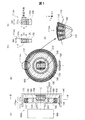
図1は、第1実施形態としてのロータリーエンコーダー100Aの構成と動作を示す説明図である。図1(A),(B)に示すように、このエンコーダー100Aは、環状の第1の磁石体110と、第1の磁石体110の内側に配置された第2の磁石体210とを有する。また、第1の磁石体110の外周に沿って第1の磁石体110の表面から一定のギャップを有して設けられた第1の2軸磁気センサー回路130と、第2の磁石体210の表面から一定のギャップを有して設けられた第2の2軸磁気センサー回路230と、を有する。2つの磁石体110,210は、支持部材150を含む略円板状の回転体400(図1(B))に設けられており、2つの2軸磁気センサー回路130,230は、基板140(図1(A))に設けられている。なお、2軸磁気センサー回路130,230は、ICパッケージの形状で描かれている。また、図1(B)では、第2の2軸磁気センサー回路230を透かして第2の磁石体210が見える状態を描いている。基板140は回転しない固定体(「第1部材」とも呼ぶ)を構成し、回転体400は回転軸Cの廻りに回転する回転体(「第2部材」とも呼ぶ)を構成している。回転体400の支持部材150は、慣性モーメントの少ない軽量剛性な非磁性材料で形成することが好ましく、例えば、アルミニウム、マグネシウム、ジュラルミン、樹脂、複合樹脂等で形成することが好ましい。第1の磁石体110の内周側には、環状の第1のヨーク部材120を設けられており、第2の磁石体210の裏側には、円板状の第2のヨーク部材220が設けられている。更に、2つの磁石体110,210の間の位置には、磁気遮蔽部材160が設けられている。これらの部材120,220,160は不要な磁束の漏れを低減するためのものであり、軟磁性体で形成することが好ましい。但し、これらの部材120,220,160の一部又は全部を省略することも可能である。このエンコーダー100Aは、任意の回転体の位置検出に適用可能であり、図1(A)の例では、モーター500の回転軸530に接続されている。
A. First embodiment (rotary encoder)
FIG. 1 is an explanatory diagram showing the configuration and operation of a
第1の磁石体110は、回転体400の外周の全周に亘って設けられた64組の小磁石ペア111psで構成された64極の磁石体である。1組の小磁石ペア111psは、第1の磁石体110の1つの磁極を構成している。個々の小磁石ペア111psは、回転体400の回転軸Cに平行な方向に沿って並んで配置された2つの小磁石111s(図1(A))で構成されている。図1(C)は、図1(B)と同様に正面方向から1組の小磁石ペア111psを見たときの断面の一部を拡大して示しており、図1(D)は、図1(A)と同様に側面方向から1組の小磁石ペア111psを見たときの断面の一部を拡大して示している。1組の小磁石ペア111psは、直方体形状を有する2つの小磁石111sと、被覆部材112とで構成されており、全体として等辺台形柱形状を有する。すなわち、正面視(図1(C))において等辺台形形状を有し、側面視(図1(D))において矩形形状を有している。平面視における等辺台形形状は、高さHと、外周の幅WDとを有する。また、側面視の矩形形状は、奥行きDP及び高さHを有する。外周の幅WDは、第1の磁石体110の直径の寸法と、第1の磁石体110の極数M1とに応じて決められる。例えば、第1の磁石体110の直径を30mmとし、その極数M1を64とし、小磁石ペア111psの高さHを5mmとした場合には、WD=1.47mmとなり、小磁石ペア111psのサイズが極めて小さなものとなる。仮に、このような微小サイズの等辺台形柱形状の全体をすべて磁石で製造しようとすると、そのためのテーパー加工が困難である。そこで、本実施形態では、直方体形状の2つの小磁石111sを被覆部材112で被覆することによって、全体として等辺台形柱形状の小磁石ペア111psを形成している。被覆部材112は、直方体形状の2つの小磁石111sの周囲の少なくとも一部を被覆し、かつ、小磁石ペア111psの全体の形状を等辺台形形状とするために設けられている部材である。被覆部材112の材料としては、加工のし易さ及び耐久性を考慮して、アルミ材や樹脂などの非磁性体材料を利用することが可能である。
The
図1(D)に拡大して示すように、個々の小磁石111sは、回転軸Cから個々の小磁石111sの中心を通る方向(すなわち径方向)に平行な方向に沿って平行着磁されている。また、各小磁石ペア111psを構成する2つの小磁石111s同士は、逆向きに磁化されている。図1(E)に示すように、多数の小磁石ペア111psを回転体400の外周に並べることによって、多極の第1の磁石体110を容易に作成することができる。例えば、64個の小磁石ペア111psを円環状に並べることによって、64極の第1の磁石体110を構成することが可能である。この構成では、小磁石ペア111psは、回転体400の回転軸C廻りの円形の軌道に沿って配置されていることが理解できる。なお、図1(A)に示すように、第1の2軸磁気センサー回路130の中心は、各小磁石ペア111psを構成する2つの小磁石111sの中間を通る直線(すなわち2つの小磁石111sの境界)が辿る軌跡の上に配置されることが好ましい。
As shown in an enlarged view in FIG. 1D, the individual
第2の磁石体210は、第1の磁石体110の内側において、エンコーダー100Aの回転軸Cの廻りに配置された2個の半円板状の小磁石211sで形成されており、全体として円板形状を有する2極の磁石体である。第2の磁石体210の個々の小磁石211sの着磁方向は、回転軸Cと平行な方向であり、2つの小磁石211sは逆方向に磁化されている。第2の磁石体210の中心は、回転体400の回転軸C上の位置に配置することが好ましい。また、第2の2軸磁気センサー回路230の中心は、回転体400の回転軸C上の位置に配置されている。
The
なお、小磁石111sを単に「磁石111s」と呼び、小磁石ペア111psを「磁石ペア111ps」と呼び、磁石体110を「磁石集合体110」と呼ぶことも可能である。小磁石211s、小磁石ペア211ps、及び磁石体210についても同様である。
The
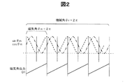
図2は、2軸磁気センサー回路130で得られる各種の検出信号sinθm,cosθm,D1を示すグラフである。なお、2つの2軸磁気センサー回路130,230の構成と動作は同一なので、以下では主として第1の2軸磁気センサー回路130を対象として説明を行う。図2のグラフの横軸は、エンコーダー100A(すなわち回転体)の回転角θrである。この回転角θrを、「機械角」とも呼ぶ。第1の磁石体110の周方向に沿った磁場は、隣接する2つの小磁石ペア111psを1周期とする正弦波状の変化を示す。この磁場の1周期毎の位置は、磁気角θmによって表される。図2の上部に示した信号sinθm,cosθmは、この磁気角θmに応じた正弦波信号及び余弦波信号である。但し、図2では、図示の便宜上、第1の磁石体110が8極の場合の例を示している。図2の下部に示した信号D1は、磁気角θmの各周期において0から最大値まで直線的に変化する信号であり、2軸磁気センサー回路130から外部回路に出力される磁気角出力D1である。磁気角出力D1は、例えば、正弦波信号sinθmと余弦波信号cosθmをデコードすることによって生成することができる。
FIG. 2 is a graph showing various detection signals sin θm, cos θm, D1 obtained by the biaxial
図3は、2軸磁気センサー回路130の内部に含まれる複数のホール素子の配列例と、それらの感磁方向を示す説明図である。ここでは、2軸磁気センサー回路130の表面に平行な方向として、互いに直交するX軸方向と、Y軸方向とを描いている。Z軸方向は、X軸方向及びY軸方向に直交しており、小磁石111s(又は211s)の着磁方向と平行な方向である。また、ホール素子の感磁方向(磁力線の検出方向)として、S極からN極に向かう方向を矢印で示している。内部に黒丸を含む白丸は、紙面の裏側から表側に向かう方向が感磁方向であることを示す。また、内部に「X」を含む白丸は、紙面の表側から裏側に向かう方向が感磁方向であることを示す。
FIG. 3 is an explanatory diagram showing an example of arrangement of a plurality of Hall elements included in the biaxial
図3(A)の2軸磁気センサー回路130は、X軸方向を感磁方向とする2つのX軸ホール素子X1,X2と、Y軸方向を感磁方向とする2つのY軸ホール素子Y1,Y2とを有している。なお、X軸ホール素子の個数は、複数とすることが好ましく、2個に限らず3個以上でも良い。これはY軸ホール素子も同様である。後述するように、複数のX軸ホール素子X1,X2から第1磁気角信号sinθmが生成され、複数のY軸ホール素子Y1,Y2から第2磁気角信号cosθmが生成される。この点はさらに後述する。
The two-axis
図3(B)の2軸磁気センサー回路130は、第1組のホール素子YX1,YX2と、第2組のホール素子XY1,XY2とを有している。これらの2組のホール素子は、X軸方向とY軸方向に対して45度傾いた方向を感磁方向としている。図3(C)の2軸磁気センサー回路130は、2つのY軸ホール素子Y1,Y2と、2つのX軸ホール素子X1,X2とを有している。図3(C)の回路は、2つのY軸ホール素子Y1,Y2と2つのX軸ホール素子X1,X2の感磁方向が互いに向き合っている点で、図3(A)の回路と異なっている。図3(D)の2軸磁気センサー回路130は、4つのY軸ホール素子Y1a,Y1b,Y2a,Y2bと、4つのZ軸ホール素子Z1a,Z1b,Z2a,Z2bとを有している。図3(D)の2軸磁気センサー回路130を用いる場合には、上方の2つのY軸ホール素子Y1a,Y1bの出力を加算し、下方の2つのY軸ホール素子Y2a,Y2bを加算すれば、図3(A)の2つのY軸ホール素子Y1,Y2の出力と等価な出力を得ることが可能である。Z軸ホール素子Z1a,Z1b,Z2a,Z2bについても同様である。図3(B)〜(D)の2軸磁気センサー回路130のいずれを使用しても、その複数のホール素子の出力を合成することによって、磁気角信号sinθm,cosθmを生成することが可能である。なお、これらの例から理解できるように、2軸磁気センサー回路130は、直交する2つの方向に沿った磁場を検出することが可能な回路である。また、2軸磁気センサー回路130において、複数個のX軸センサー素子が、X軸に沿って互いに離れた部位に配置された第1組のX軸ホール素子と第2組のX軸ホール素子とを含み、同様に、複数個のY軸センサー素子が、Y軸に沿って互いに離れた部位に配置された第1組のY軸ホール素子と第2組のY軸ホール素子とを含むように構成することが可能である。なお、2軸磁気センサー回路130の中心は、これらの複数のホール素子の間の中央位置に一致している。
The biaxial
図4は、2軸磁気センサー回路130の回路構成と動作を示す説明図である。ここでは、図3(A)に示したホール素子の構成を使用している。2軸磁気センサー回路130は、X軸ホール素子X1,X2及びY軸ホール素子Y1,Y2の他に、増幅回路131,132と、AD変換回路133,134と、信号処理回路135とを有している。第1の増幅回路131には2つのX軸ホール素子X1,X2の出力が入力され、第2の増幅回路132には2つのY軸ホール素子Y1,Y2の出力が入力されている。図4(B)に示すように、2つのX軸ホール素子X1,X2の出力は、それぞれ第1の正弦波状の信号である。また、2つのY軸ホール素子Y1,Y2の出力は、第1の正弦波から90度位相がずれた第2の正弦波状(余弦波状)の信号である。第1の増幅回路131は、2つのX軸ホール素子X1,X2の出力の差分(X1−X2)を取る差動増幅器として構成されている。この理由は、第1の増幅回路131に入力される2つのX軸ホール素子X1,X2の出力の正負の符号が逆となるように、ホール素子X1,X2の回路や配線が構成されているからである。図4(B)の例では、2つのX軸ホール素子X1,X2の出力は、符号が逆で絶対値が等しい信号として描かれている。但し、2軸磁気センサー回路130の設置位置や磁石の磁束歪みによる磁極位置によっては、これらの2つのX軸ホール素子X1,X2の出力の絶対値が互いに異なる場合もある。しかし、この場合にも、第1の増幅回路131で2つのX軸ホール素子X1,X2の出力の差分(X1−X2)を取ることによって、2軸磁気センサー回路130の設置位置や磁石の磁束歪みによる磁極位置のずれに関わらず、磁気角θmに応じた正しい正弦波出力を得ることが可能である。これらの点は、Y軸ホール素子Y1,Y2及び第2の増幅回路132に関しても同様である。このように、複数のX軸ホール素子の出力信号の差を取ることによって正弦波信号(X1−X2)を生成し、複数のY軸ホール素子の出力信号の差を取ることによって正弦波信号(X1−X2)とは位相が90度異なる余弦波信号(Y1−Y2)を生成することができる。また、正弦波信号(X1−X2)と余弦波信号(Y1−Y2)に基づいて、回転体の位置(回転位置)を示す磁気角出力D1を生成することができる。
FIG. 4 is an explanatory diagram showing the circuit configuration and operation of the biaxial
なお、第1の増幅回路131に入力される2つのX軸ホール素子X1,X2の出力は、正負符号が同一の信号としてもよい。この場合には、第1の増幅回路131は、加算増幅器として構成される。但し、第1の増幅回路131を差動増幅器として構成すれば、2つの出力信号X1,X2に共通のノイズ(例えば、電磁コイルのPWM制御に伴う高周波ノイズ)が含まれている場合にも、それらの差分(X−X2)を取ることによってノイズを軽減できる点で好ましい。これらの点は、第2の増幅回路132も同様である。
Note that the outputs of the two X-axis Hall elements X1 and X2 input to the
これらの増幅回路131,132の出力(X1−X2),(Y1−Y2)は、AD変換回路133,134でそれぞれデジタル信号に変換されて、磁気角信号sinθm,cosθmとなる。信号処理回路135は、これらの磁気角信号sinθm,cosθmに基づいたデコード演算を行うことによって、図2に示した磁気角出力D1を生成する。信号処理回路135は、更に、磁気角出力D1を利用して、図4(C)に示す2相パルス信号Pa,Pbと、周期信号Zとを生成する。
The outputs (X1-X2) and (Y1-Y2) of the
2相パルス信号Pa,Pbと、周期信号Zは、例えば以下のように生成される。磁気角出力D1は、磁気角θmを複数のビットで表した信号である。例えば、磁気角出力D1が12ビット信号として構成されている場合には、磁気角θmが0から2πまで変化する間に、磁気角出力D1の値は0から4095(=212−1)まで直線的に変化する。2相パルス信号Pa,Pbは、位相が互いに90度ずれた信号であり、光学式のインクリメンタルエンコーダーのA相出力及びB相出力に相当する信号である。周期信号Zは、磁気角θmが2π変化するたびに1パルス発生する信号であり、光学式のインクリメンタルエンコーダーのZ相信号に相当する信号である。例えば、A相パルス信号Paは、磁気角出力D1の最下位から2番目のビットの変化を示す信号として生成される。また、B相パルス信号Pbは、角度信号D1の最下位の2ビットの排他的論理和(XOR)を取った信号として生成される。周期信号Zは、角度信号D1の全ビットの否定論理和(NOR)を取った信号として生成される。角度信号D1が12ビットの信号の場合には、2相パルス信号Pa,Pbのパルスは、磁気角θmが2π変化する間に1024個発生する。 The two-phase pulse signals Pa and Pb and the periodic signal Z are generated as follows, for example. The magnetic angle output D1 is a signal representing the magnetic angle θm by a plurality of bits. For example, when the magnetic angle output D1 is configured as a 12-bit signal, the value of the magnetic angle output D1 is 0 to 4095 (= 2 12 −1) while the magnetic angle θm changes from 0 to 2π. It changes linearly. The two-phase pulse signals Pa and Pb are signals whose phases are shifted from each other by 90 degrees, and are signals corresponding to an A-phase output and a B-phase output of an optical incremental encoder. The periodic signal Z is a signal that generates one pulse every time the magnetic angle θm changes by 2π, and is a signal that corresponds to the Z-phase signal of the optical incremental encoder. For example, the A-phase pulse signal Pa is generated as a signal indicating a change in the second least significant bit of the magnetic angle output D1. The B-phase pulse signal Pb is generated as a signal obtained by taking an exclusive OR (XOR) of the least significant 2 bits of the angle signal D1. The periodic signal Z is generated as a signal obtained by taking a negative logical sum (NOR) of all bits of the angle signal D1. When the angle signal D1 is a 12-bit signal, 1024 pulses of the two-phase pulse signals Pa and Pb are generated while the magnetic angle θm changes by 2π.
信号処理回路135は、角度信号D1と、正弦波信号sinθmと、余弦波信号cosθmと、2相パルス信号Pa,Pbと、周期信号Zとを外部に出力することが可能である。ロータリーエンコーダー100Aを使用する装置は、これらの信号のうちのいくつかを用いて位置制御や速度制御を実行することが可能である。
The
ところで、図1でも述べたように、第1の磁石体110の個々の小磁石111sは、回転軸Cから個々の小磁石111sの中心を通る方向に平行な方向に磁化されており、第1の2軸磁気センサー回路130は、そのZ軸(図3)が小磁石111sの磁化方向と平行となるように配置されている。また、第2の磁石体210の個々の小磁石211sは、回転軸Cに平行な方向に磁化されており、第2の2軸磁気センサー回路230は、そのZ軸が小磁石211sの磁化方向と平行となるように配置されている。このような配置を採用した理由は、以下で説明する実験結果を考慮したものである。
By the way, as described in FIG. 1, the individual
図5は、小磁石に対する2軸磁気センサー回路の配置に応じた2軸磁気センサー回路の出力レベルを示す説明図である。図5(A)に示すように、ここでは、円板状の支持部材150の外周に多数の小磁石111sを設けている。但し、図5(A)では図示の便宜上、全体の1/8に相当する部分(中心角で45度の部分)のみを示しており、小磁石111sは8個設けられている。図5(B)は、図5(A)の断面図であり、1つの小磁石111sの断面が示されている。個々の小磁石111sの磁化方向は、回転軸Cから個々の小磁石111sの中心に向かう方向(すなわち径方向)に平行である。この実験では、第1の測定位置SP1と、第2の測定位置SP2に2軸磁気センサー回路130を配置し、それぞれの位置SP1,SP2において磁場をそれぞれ測定した。第1の測定位置SP1は、複数の小磁石111sの表面から上方に0.5mm離れた位置であり、2軸磁気センサー回路130の2つの感磁軸方向(図4のX,Y軸方向)で規定される平面が、小磁石111sの着磁方向と平行となるように2軸磁気センサー回路130を設置した。なお、「2つの感磁軸方向で規定される表面」は、2軸磁気センサー回路130の感磁面に相当する。なお、2軸磁気センサー回路130の感磁面は、2軸磁気センサー回路130内に設けられた磁性体の表面と平行な面として規定することも可能である。第2の測定位置SP2は、複数の小磁石111sの外周から0.5mm離れた位置であり、2軸磁気センサー回路130の感磁面が、小磁石111sの着磁方向と直交するように2軸磁気センサー回路130を設置した。図5(C)は、これらの2つの測定位置SP1,SP2における2軸磁気センサー回路130の出力レベルを示している。これから理解できるように、第2の測定位置SP2で検出される磁場の強度は、第1の測定位置SP1で検出される磁場の強度よりも極めて高い。従って、2軸磁気センサー回路130は、その感磁面が、小磁石111sの着磁方向と直交するように設置することが好ましい。換言すれば、小磁石111sは、2軸磁気センサー回路130の感磁面に直交する方向に磁化されていることが好ましい。こうすれば、2軸磁気センサー130の信号レベルがより大きくなるので、エンコーダーの測定精度をより高めることが可能である。なお、小磁石111sの磁化方向は、2軸磁気センサー回路130の感磁面に直交する必要は無いが、2軸磁気センサー回路130の感磁面に交差する方向であることが好ましく、感磁面に直交する方向であることが最も好ましい。
FIG. 5 is an explanatory diagram showing the output level of the biaxial magnetic sensor circuit according to the arrangement of the biaxial magnetic sensor circuit with respect to the small magnet. As shown in FIG. 5A, here, a large number of
図6は、第1の2軸磁気センサー回路130から出力される第1磁気角出力D1と、第2の2軸磁気センサー回路230から出力される第2磁気角出力D2と、の例を示す説明図である。図6の横軸は機械角θrであり、縦軸は2つの2軸磁気センサー回路130,230の磁気角出力D1,D2である。但し、図6では、図示の便宜上、第1の磁石体110が8極の例を示している。第1の磁石体110が8極の場合には、エンコーダー100Aの支持部材150の1回転(機械角で360度)の間に、第1の磁石体110の小周期区間が4つ発生する。ここで、「小周期区間」とは、第1の磁石体110の磁気角θmが360度(2π)変化する区間を意味する。図6(A)に示す小周期区間値Pxは、これらの4つの小周期区間を区別するための値であり、0〜3までの4つの値を取る。後述するように、この小周期区間値Pxは、第2の2軸磁気センサー回路230の磁気角出力から生成される。なお、第1の磁石体110が64極の場合には、エンコーダー100Aの支持部材150の1回転の間に、第1の磁石体110の小周期区間が32個発生する。但し、図6において、エンコーダー100Aの支持部材150の1回転の間に第1の磁石体110の小周期区間が32個発生する図を描くと過度に細かな図となるので、ここでは図示の便宜上、簡略化した図を用いている。
FIG. 6 shows an example of the first magnetic angle output D1 output from the first two-axis
図6の例では、2軸磁気センサー回路130,230の磁気角出力D1,D2は、いずれも12ビットで構成されており、磁気角出力D1,D2は0〜4095の間の値を取る。但し、一般には、第1の2軸磁気センサー回路130の第1磁気角出力D1をN1ビット(N1は2以上の整数)のデジタル信号とし、第2の2軸磁気センサー回路230の第2磁気角出力D2をN2ビット(N2は2以上の整数)のデジタル信号とすることができる。ここで、ビット数N1,N2は、同じ値としても良く、異なる値としても良い。
In the example of FIG. 6, the magnetic angle outputs D1 and D2 of the biaxial
図6(B)に示す第1磁気角出力D1は、第1の磁石体110の回転に伴う磁気角の変化を示しており、機械角θrが360度変化する間に、0から4095までの値が4回繰り返し発生する鋸刃状の変化を示す。すなわち、第1磁気角出力D1は、個々の小周期区間の間に、0から4095まで増加する直線的な変化を示す。一方、図6(A)に示す第2磁気角出力D2は、第2の磁石体210の回転に伴う磁気角の変化を示しており、機械角θrが360度変化する間に0から4095までの値が1回だけ発生する直線的な変化を示す。第2磁気角出力D2の最上位2ビットは、図6(A)に示す小周期区間値Pxとして使用可能である。
The first magnetic angle output D1 shown in FIG. 6B shows the change of the magnetic angle accompanying the rotation of the
小周期区間値Pxは、機械角θrの絶対位置を高精度に決定するために使用される。機械角θrは、第2磁気角出力D2のみから12ビットの精度で検出可能である。しかし、小周期区間値Pxと第1磁気角出力D1との両方を使用すれば、更に高精度(高分解能)に機械角θrの絶対位置を決定することができる。具体的には、図6の例において、小周期区間値Pxが2ビットであり、第1磁気角出力D1が12ビットなので、これらの両方を使用して14ビットの精度(分解能)で機械角θrを検出可能である。 The short period interval value Px is used to determine the absolute position of the mechanical angle θr with high accuracy. The mechanical angle θr can be detected with an accuracy of 12 bits only from the second magnetic angle output D2. However, if both the short period interval value Px and the first magnetic angle output D1 are used, the absolute position of the mechanical angle θr can be determined with higher accuracy (high resolution). Specifically, in the example of FIG. 6, since the short period interval value Px is 2 bits and the first magnetic angle output D1 is 12 bits, both of these are used to obtain a mechanical angle with a precision (resolution) of 14 bits. θr can be detected.
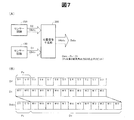
図7は、2つの2軸磁気センサー回路130,230の出力を用いて回転体の絶対位置(絶対角度)を決定する位置信号生成部300を示す説明図である。位置信号生成部300は、2つの2軸磁気センサー回路130,230の磁気角出力D1,D2を合成して、絶対位置出力Dabsを生成する。図7(B)は、位置信号生成部300の処理内容を示している。この例では、第1磁気角出力D1は、最下位ビットM0から最上位ビットM11までの12ビットの信号であり、第2磁気角出力D2も、最下位ビットS0から最上位ビットS11までの12ビットの信号である。第2磁気角出力D2の最上位2ビットS11,S10は、小周期区間値Pxとして使用される。絶対位置出力Dabsは、その最上位2ビットが小周期区間値Pxであり、下位12ビットが第1磁気角出力D1である。この絶対位置出力Dabsは、14ビットの精度で機械角θrの値を表す信号である。
FIG. 7 is an explanatory diagram showing a
なお、本実施形態において、2軸磁気センサー回路130,230のそれぞれは、複数のホール素子(図3の例参照)を用いている。従って、2軸磁気センサー回路130,230の電源がオンとなったときに、その時点における回転体の絶対位置(機械角θr)に応じて、図6に示した磁気角出力D1,D2を得ることができ、これらの磁気角出力D1,D2に応じて回転体の絶対位置(機械角θr)を決定することが可能である。従って、2軸磁気センサー回路130,230の電源オフ時に、その時点における回転体の絶対位置(機械角θrの値)を記憶しておく必要が無く、電源オン時に得られる2つの磁気角出力D1,D2のみから、電源オフ時の回転体の絶対位置を知ることができるという利点がある。
In the present embodiment, each of the biaxial
ところで、図6の例では、第1磁気角出力D1の小周期区間の境界と、第2磁気角出力D2から得られる小周期区間値Pxの値の変化位置とが一致している。しかしなら、実際の回路では、何らかの誤差によって両者が食い違う不具合が発生する可能性がある。このような不具合を防止するために、位置信号生成部300は、機械角θrの増大に応じて第1磁気角出力D1が最大値D1maxから最小値0に戻るタイミングと、小周期区間値Px(すなわち第2磁気角出力D2の最上位2ビット)がインクリメントするタイミングとが一致するように、小周期区間値Pxの補正を行うことが好ましい。
Incidentally, in the example of FIG. 6, the boundary of the short period interval of the first magnetic angle output D1 and the change position of the value of the short period interval value Px obtained from the second magnetic angle output D2 coincide. However, in an actual circuit, there is a possibility that a problem in which the two differ due to some error. In order to prevent such inconvenience, the position
図8は、位置信号生成部300によって行われる小周期区間値Pxの補正対象範囲を示す説明図である。図の下方には、第1磁気角出力D1の鋸刃状の変化が示されており、上方には第2磁気角出力D2の誤差の幅(上下方向の幅)がハッチングで示されている。第1磁気角出力D1は、その最小値0から最大値D1maxの範囲で変化しており、最大値D1maxに到達したあとに、最小値0に戻る。第1磁気角出力D1が最大値D1maxから最小値0に戻るタイミングと、第2磁気角出力D2の最上位2ビットがインクリメントするタイミングとが一致していれば、図7(B)で示したように、第2磁気角出力D2の最上位2ビットを小周期区間値Pxとしてそのまま使用できる。一方、両者のタイミングがずれている場合には、小周期区間値Pxの補正を行う。小周期区間値Pxの補正が必要となるのは、第1磁気角出力D1が最大値D1maxから最小値0に戻るタイミングの直後の範囲R1と、そのタイミングの直前の範囲R3である。これらの2つの範囲R1,R3の中間の範囲R2では、第2磁気角出力D2の最上位2ビットの値が、小周期区間値Pxとして正しい値を示すので、補正の必要は無い。
FIG. 8 is an explanatory diagram illustrating a correction target range of the short cycle interval value Px performed by the position
図9は、小周期区間値Pxの補正のアルゴリズムの一例を示すフローチャートである。この補正は、位置信号生成部300(図7)によって行われる。ステップS100では、第1磁気角出力D1のビット数N1と、第2磁気角出力D2のビット数N2と、小周期区間値Pxのビット数Nxと、が設定される。また、パラメータNss(=N2−Nx)、D1max(=2N1−1)も設定される。本実施形態では、N1=N2=12,Nx=2,Nss=10,D1max=4095である。 FIG. 9 is a flowchart illustrating an example of an algorithm for correcting the short cycle interval value Px. This correction is performed by the position signal generator 300 (FIG. 7). In step S100, the bit number N1 of the first magnetic angle output D1, the bit number N2 of the second magnetic angle output D2, and the bit number Nx of the short period interval value Px are set. Parameters Nss (= N2−Nx) and D1max (= 2 N1 −1) are also set. In this embodiment, N1 = N2 = 12, Nx = 2, Nss = 10, and D1max = 4095.
ステップS110では、位置信号生成部300が、2つの2軸磁気センサー回路130,230(図7)から磁気角出力D1,D2を受信する。ステップS120では、第1磁気角出力D1が、図8に示した3つの範囲R1,R2,R3のいずれにあるかが判定される。図9の例では、第1の範囲R1を0≦D1≦(D1max/4)とし、第2の範囲R2を(D1max/4)<D1<(D1max*3/4)とし、第3の範囲R3を(D1max*3/4)≦D1≦D1maxとしている。第1の範囲R1と第3の範囲R3では、小周期区間値Pxを補正するために、第2磁気角出力D2の補正を実行する。
In step S110, the
補正の実行工程であるステップS130〜S150は、以下の考えに基づいて実施される。
(1)第1磁気角出力D1が第1の範囲R1にある場合には、第2磁気角出力D2の上位2ビットで表される小周期区間値Pxが、誤って1つ小さな値になっている可能性がある。そこで、この可能性を排除するために、第2磁気角出力D2の下位Nssビットで表される最大値(=2Nss)の半分の値を第2磁気角出力D2に加算して、その上位Nxビットを小周期区間値Pxとして使用する(ステップS130,S150)。
(2)第1磁気角出力D1が第2の範囲R2にある場合には、第2磁気角出力D2の最上位2ビットをそのまま小周期区間値Pxとして使用する(ステップS150)。
(3)第1磁気角出力D1が第3の範囲R3にある場合には、第2磁気角出力D2の上位2ビットで表される小周期区間値Pxが、誤って1つ大きな値になっている可能性がある。そこで、この可能性を排除するため、第2磁気角出力D2の下位Nssビットで表される最大値(=2Nss)の半分の値を第2磁気角出力D2から減算して、その上位Nxビットを小周期区間値Pxとして使用する(ステップS140,S150)。
Steps S130 to S150, which are correction execution steps, are performed based on the following idea.
(1) When the first magnetic angle output D1 is in the first range R1, the short period interval value Px represented by the upper 2 bits of the second magnetic angle output D2 is erroneously reduced by one. There is a possibility. Therefore, in order to eliminate this possibility, a value half of the maximum value (= 2 Nss ) represented by the lower Nss bits of the second magnetic angle output D2 is added to the second magnetic angle output D2, and its upper Nx bits are used as the short cycle interval value Px (steps S130 and S150).
(2) When the first magnetic angle output D1 is in the second range R2, the most significant 2 bits of the second magnetic angle output D2 are used as they are as the short period interval value Px (step S150).
(3) When the first magnetic angle output D1 is in the third range R3, the short period interval value Px represented by the upper 2 bits of the second magnetic angle output D2 is erroneously increased by one. There is a possibility. Therefore, in order to eliminate this possibility, a value half of the maximum value (= 2 Nss ) represented by the lower Nss bits of the second magnetic angle output D2 is subtracted from the second magnetic angle output D2, and its upper Nx The bit is used as the short cycle interval value Px (steps S140 and S150).
このような補正を行うことによって、第1磁気角出力D1の小周期区間の境界と、小周期区間値Pxの変化時点とが常に一致するように、小周期区間値Pxを決定することが可能である。発明者の計算によれば、第2磁気角出力D2の磁気角誤差が±2N1-Nx-2以下であれば、上記の補正によって正しい小周期区間値Pxを得ることが可能である。例えば、N1=12,Nx=2の場合には、許容誤差は±28=±256である。この許容誤差はかなり大きいので、誤差に対する耐性が非常に大きく、実用上極めて有効な補正であることが理解できる。但し、磁気角出力D1,D2の誤差が無視できる程度のものであれば、小周期区間値Pxの補正は不要である。 By performing such correction, it is possible to determine the short cycle interval value Px so that the boundary of the short cycle interval of the first magnetic angle output D1 always coincides with the change point of the short cycle interval value Px. It is. According to the inventor's calculation, if the magnetic angle error of the second magnetic angle output D2 is ± 2 N1−Nx−2 or less, it is possible to obtain a correct small period interval value Px by the above correction. For example, if N1 = 12, Nx = 2, the tolerance is ± 2 8 = ± 256. Since this allowable error is quite large, it can be understood that the tolerance to the error is very large and that the correction is extremely effective in practice. However, if the error of the magnetic angle outputs D1 and D2 is negligible, the correction of the short period interval value Px is not necessary.
なお、補正を要する範囲R1,R3の最小幅は、磁気角出力D1,D2の誤差の大きさに応じて変わる。従って、これらの3つの範囲R1〜R3を、上述とは異なる所定の範囲にそれぞれ設定することが可能である。但し、3つの範囲R1〜R3のそれぞれは、幅がゼロでない範囲とすることが好ましい。また、小周期区間の境界の両側にある範囲R1,R3は、同じ幅とすることが好ましい。 Note that the minimum widths of the ranges R1 and R3 that require correction vary depending on the magnitude of the error in the magnetic angle outputs D1 and D2. Therefore, these three ranges R1 to R3 can be set to predetermined ranges different from those described above. However, each of the three ranges R1 to R3 is preferably set to a range in which the width is not zero. Moreover, it is preferable that the ranges R1 and R3 on both sides of the boundary of the short cycle section have the same width.
このように、位置信号生成部300は、第1の2軸磁気センサー回路130の第1磁気角出力D1と、第2の2軸磁気センサー回路230の第2磁気角出力D2とに応じて、回転体の絶対位置(機械角θr)を示す位置信号(絶対位置出力Dabs)を生成する。この位置信号Dabsを使用すれば、1つの2軸磁気センサー回路130(又は230)よりも高精度(高解像度)で位置を決定することが可能である。また、上述したように、本実施形態では、2軸磁気センサー回路130,230が複数のホール素子を用いているので、2軸磁気センサー回路130,230の電源オン時に得られる2つの磁気角出力D1,D2のみから、電源オフ時の回転体の絶対位置を直読で知ることができる。
As described above, the position
なお、第1の磁石体110の極数をM1とし、第2の磁石体210の極数をM2とした場合に、M1,M2をそれぞれ偶数とすることが好ましく、特に、M1を4以上の偶数とし、M2を2以上の偶数とすることが好ましい。こうすれば、1つの磁石体を用いる場合に比べて、より高精度に位置検出を行うことが可能である。
In addition, when the number of poles of the
また、第1の磁石体110の極数M1と、第2の磁石体210の極数M2は、M1/2とM2/2が互いに素である整数であることが好ましい。ここで、2つの整数が「互いに素」とは、両者が1以外の共通の約数を持たないことを意味する。M1/2とM2/2が互いに素となる整数であれば、第1の磁石体110の磁気角2πの区間(図6の小周期区間)の境界と、第2の磁石体210の磁気角2πの区間の境界とが一致する位置が、機械角θr=0の位置だけになるので、2つの磁気角出力D1,D2から機械角θrの絶対値を決定することができる。なお、図6及び図7の例では、M1=8=23,M2=2である。また、図1に示すエンコーダー100Aでは、M1=64=26,M2=2である。
The number of poles M1 of the
一般に、第2磁気角出力D2の最上位の数ビットを小周期区間値Pxとして利用するためには、第1の磁石体110の極数M1を2Q+1(Qは1以上の整数)に設定し、第2の磁石体210の極数M2を2に設定することが好ましい。このとき、位置信号生成部300は、第2磁気角出力D2の最上位Qビットを最上位に配置するとともに、その下に、第1磁気角出力D1の全ビット(N1ビット)を配置した(N1+Q)ビットの信号を、絶対位置出力Dabsとして生成することが好ましい。例えば、図6,図7の例では、N1=12,Q=2なので、絶対位置出力Dabsは14ビットの信号となる。
Generally, in order to use the most significant bits of the second magnetic angle output D2 as the short period interval value Px, the number of poles M1 of the
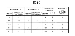
図10は、第1の磁石体110の極数M1を変更した場合の絶対位置出力Dabsのビット数を示す説明図である。この例では、2つの磁気角出力D1,D2のビット数はいずれも12ビットと仮定している。第1の磁石体110の極数M1が変わると、これに応じてエンコーダー100Aの回転体400の一回転当たりの小周期区間の発生個数が変化するので、小周期区間値Pxのビット数Qもこれに応じて変化する。絶対位置出力Dabsのビット数は、上述したように、第1磁気角出力D1のビット数N1と、小周期区間値Pxのビット数Qとを足した値(N1+Q)となる。
FIG. 10 is an explanatory diagram showing the number of bits of the absolute position output Dabs when the number of poles M1 of the
このように、第1実施形態のロータリーエンコーダー100Aは、第1の磁石体110に含まれる個々の小磁石111sが、2軸磁気センサー回路130の感磁面に交差する方向に磁化されているので、2軸磁気センサー回路130が強い磁場を検出することができ、この結果、解像度の高い磁気角出力D1を得ることが可能である。また、2軸磁気センサー回路130は、複数のX軸ホール素子X1,X2と複数のY軸ホール素子Y1,Y2とを有しており、それらのホール素子の出力信号に応じて磁気角出力D1を生成するので、第1の磁石体110に対して2軸磁気センサー回路130の設置位置が多少ずれた場合にも、正確な磁気角出力D1を得ることが可能である。これらの特徴点は、第2の磁石体210及び第2の2軸磁気センサー回路230についても同様である。
Thus, in the
更に、第1実施形態では、位置信号生成部300が、第1の2軸磁気センサー回路130の第1磁気角出力D1と第2の2軸磁気センサー回路230の第2磁気角出力D2とに応じて位置信号Dabsを生成するので、1つの2軸磁気センサー回路のみを用いる場合に比べて更に高精度に位置検出を行うことが可能である。
Furthermore, in the first embodiment, the position
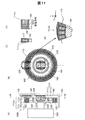
B.第2〜6実施形態(ロータリーエンコーダー)
図11は、第2実施形態としてのロータリーエンコーダー100Bの構成を示す説明図である。このロータリーエンコーダー100Bが第1実施形態のロータリーエンコーダー100A(図1)と異なる点は、第1の磁石体110が回転体400の外周では無く、回転体400の表面に設けられている点、及び、第1の2軸磁気センサー回路130の配置が第1の磁石体110の位置に応じて変更されている点である。すなわち、第2実施形態のエンコーダー100Bでは、第1の磁石体110の小磁石ペア111psを構成する2つの小磁石111sは、回転体400の径方向に沿って配列されている。また、個々の小磁石111sは、回転体400の回転軸Cに平行な方向に磁化されている。また、第1の2軸磁気センサー回路130は、そのZ軸方向が、これらの小磁石111sの磁化方向と一致するように配置されている。なお、第2実施形態は、複数組の小磁石ペア111psが、回転体400の回転軸C廻りの円形の軌道に沿って配置されている点で、第1実施形態と共通していることが理解できる。また、第1の2軸磁気センサー回路130の中心が、各小磁石ペア111psを構成する2つの小磁石111sの間の中間を通る直線が辿る軌跡の上に配置されている点でも第1実施形態と共通している。なお、第2の磁石体210と第2の2軸磁気センサー回路230の配置は第1実施形態と同じである。第2実施形態のロータリーエンコーダー100Bでは、2つの2軸磁気センサー回路130,230を同一平面上に並べて配置できるので、2軸磁気センサー回路130,230の設置や配線の引き回しが第1実施形態に比べて容易である。
B. Second to sixth embodiments (rotary encoder)
FIG. 11 is an explanatory diagram showing a configuration of a
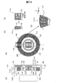
図12は、第3実施形態としてのロータリーエンコーダー100Cの構成を示す説明図である。このロータリーエンコーダー100Cが第2実施形態のロータリーエンコーダー100B(図11)と異なる点は、第2の磁石体210が円板状では無く、直方体状である点だけであり、第1の磁石体110を含む回転体400のその他の構成は第2実施形態と同じである。第3実施形態のロータリーエンコーダー100Cでは、第2の磁石体210が直方体状なので、その製造がより容易であるという利点がある。
FIG. 12 is an explanatory diagram showing a configuration of a
図13は、第4実施形態としてのロータリーエンコーダー100Dの構成を示す説明図である。このロータリーエンコーダー100Dが第2実施形態のロータリーエンコーダー100B(図11)と異なる点は、第1の磁石体110の小磁石ペア111psを構成する2つの小磁石111sが互いに密着(又は接触)しておらず、離間している点だけであり、第2の磁石体210を含む回転体400のその他の構成は第2実施形態と同じである。第4実施形態のロータリーエンコーダー100Dでは、2つの小磁石111sの間の距離と、2つの小磁石111sの間に設ける部材の材質と、の少なくとも一方を調整することによって、第1の2軸磁気センサー回路130の検出信号sinθm,cosθm(図2)の形状を、より正弦波に近いものに調整することが可能である。
FIG. 13 is an explanatory diagram showing a configuration of a
図14は、第5実施形態としてのロータリーエンコーダー100Eの構成を示す説明図である。このロータリーエンコーダー100Eが第2実施形態のロータリーエンコーダー100B(図11)と異なる点は、第2の磁石体210が、2組の小磁石ペア211psで構成されている点だけであり、第1の磁石体110を含む回転体400のその他の構成は第2実施形態と同じである。第2の磁石体210の全体は、中空円筒状であり、各組の小磁石ペア211psは半円筒状である。また、小磁石ペア211psを構成する2つの小磁石211sも、半円筒状である。個々の小磁石211sの磁化方向は、回転体400の回転軸Cに平行な方向であり、2つの小磁石211sは互いに逆向きに磁化されている。この第2の磁石体210の極数は2である。但し、小磁石ペア211psの円弧の角度をより小さくして、中空円筒状の第2の磁石体210を構成する小磁石ペア211psの数を増加すれば、第2の磁石体210の極数を任意に変更することが可能である。
FIG. 14 is an explanatory diagram showing a configuration of a
図15は、第6実施形態としてのロータリーエンコーダー100Fの構成を示す説明図である。このロータリーエンコーダー100Fは、中空円筒状の支持部材150の廻りに、同径の環状の2つの磁石体110,210が、回転軸Cに平行な方向に沿って並列に配置された構成を有している。2つの磁石体110,210の内周には、ヨーク部材120,220がそれぞれ設けられている。また、2つの磁石体110,210の間には、磁気遮蔽部材160が設けられている。基板140には、2つの磁石体110,210の外周面に対して所定のギャップを介した位置に2軸磁気センサー回路130,230が設けられている。
FIG. 15 is an explanatory diagram showing a configuration of a
第1の磁石体110は8組の小磁石ペア111psで構成されており、その極数M1は8である。第2の磁石体210は2組の小磁石ペア211psで構成されており、その極数M2は2である。但し、これらの極数M1,M2は、図10で説明したように、種々の整数に設定することが可能である。2つの磁石体110,210の個々の小磁石111s,211sの着磁方向は、回転軸Cから各小磁石111s,211sの中心を通る方向(径方向)に平行な方向である。この着磁方向は、2軸磁気センサー回路130,230のZ軸方向に平行である。他の構成や動作は、第1〜第5実施形態で説明したものと同様である。
The
第2〜第6実施形態のロータリーエンコーダー100B〜100Fも、第1実施形態と同様の効果を有する。第1〜第5実施形態のように円板状の回転体400に設けられた2つの磁石体110,210を使用するか、あるいは、第6実施形態のように円筒状の回転体(支持部材150)に設けられた同径の2つの磁石体110、210を使用するかは、エンコーダーの用途や空間的制約によって適宜選択可能である。例えば、より外径の小さな空間にエンコーダーを配置したい場合には、第6実施形態の方が第1〜第5実施形態よりも有利である。
The rotary encoders 100B to 100F of the second to sixth embodiments also have the same effect as that of the first embodiment. The two
C.第7実施形態(エンコーダーを備える電気機械装置)
図16は、本発明の実施形態としてのロータリーエンコーダーを備える電動モーター500の電気的構成を示すブロック図である。電動モーター500のモーター部として、ローター510と、2相分の電磁コイル522A,522Bが描かれている。電磁コイル522A,522Bは、図示しないステーターに設けられている。電動モーター500の回転軸530には、2つの2軸磁気センサー回路130,230を含むロータリーエンコーダー100が接続されている。このロータリーエンコーダー100としては、上述した第1〜第6実施形態のエンコーダーを利用可能である。制御部600は、主制御回路610と、2相分の駆動信号生成部620A,620Bと、2相分の駆動回路630A,630Bとを有している。主制御回路610には、第1の2軸磁気センサー回路130の出力信号D1,Pa,Pb,Z(図4参照)と、第2の2軸磁気センサー回路230の出力信号D2とが供給されており、これらの信号に基づいて、位置制御や速度制御を実行する。主制御回路610の内部構成については後述する。2相分の駆動信号生成部620A,620Bは、1つの2軸磁気センサー回路130から、正弦波と余弦波を示すデジタル信号sinθm,cosθmを受け取り、これらのデジタル信号sinθm,cosθmに基づくPWM制御を実行することによって2相分の駆動信号を生成する。これらの駆動信号は、駆動回路630A,630Bにそれぞれ供給される。駆動回路630A,630Bは、いわゆるブリッジドライバー回路である。正弦波状のデジタル信号sinθm,cosθmに基づくPWM制御によって2相分の駆動信号を生成する方法や、その回路構成については、例えば、本出願人により開示された特開2008−17678号公報の図10に示された回路(AD変換部を除く)を利用することが可能である。なお、本実施形態では、1つの2軸磁気センサー回路130から出力される正弦波信号sinθmと余弦波信号cosθmとを用いて2相分の駆動信号を生成するので、2つの磁気センサーを用いる場合に比べて、2つのセンサー位置相互のズレに起因する駆動信号の位相ズレが発生しない点で好ましい。この結果、モータの効率を高めることが可能である。
C. Seventh embodiment (electromechanical device including an encoder)
FIG. 16 is a block diagram showing an electrical configuration of an
図17は、主制御回路610の内部構成を示すブロック図である。主制御回路610の通信インターフェイス710は、第1の2軸磁気センサー回路130から第1磁気角出力D1を受信し、第2の2軸磁気センサー回路230から第2磁気角出力D2を受信する。受信された磁気角出力D1,D2は、データ受信部720を介して位置信号生成部730に供給される。この位置信号生成部730は、図7〜図9で説明した位置信号生成部300と同じ機能を有する。位置信号生成部730で得られた絶対位置出力Dabsは、角速度算出部740に供給され、ローター510の角速度(回転速度)が算出される。また、この角速度は、角加速度算出部750に供給され、ローター510の角加速度が算出される。第1の2軸磁気センサー回路130の出力信号Pa,Pb,Z(図4)は、回転数算出部760に供給される。
FIG. 17 is a block diagram showing the internal configuration of the
図18は、回転数算出部760の内部構成と動作を示す説明図である。B相パルス信号Pbは、Dフリップフロップ761のデータ入力端子に供給され、A相パルス信号Paはクロック端子に供給される。Dフリップフロップ761の出力であるアップダウン信号Ua/Daは、アップダウンカウンター762の入力端子に供給される。アップダウン信号Ua/Daのハイレベルは、ローター510の回転方向が正方向(順方向)であることを示し、ローレベルは逆方向であることを示す。アップダウンカウンター762のクロック端子には、周期信号Zが供給されており、周期信号の立ち上がりエッジに応じてカウント値を変更する。すなわち、アップダウン信号Ua/Daがハイレベルの場合にはカウント値が1つインクリメントされ、アップダウン信号Ua/Daがローレベルの場合にはカウント値が1つデクリメントされる。アップダウンカウンター762のカウント値は、ラッチ763に供給される。ラッチ763のクロック端子には、周期信号Zが供給されており、周期信号Zの立ち下がりエッジに応じてカウント値Dnがラッチ763に保持される。ラッチ763の出力は、ローター510の回転数Nrとして外部に出力される。この回転数Nrは、電動モーター500によって駆動される部材(例えばロボットの関節)に関して、その所定の基準位置からの電動モーター500の回転数を示している。この回転数Nrは、回転数記憶部770(図17)に供給されて記憶される。
FIG. 18 is an explanatory diagram showing the internal configuration and operation of the rotation
図17の主制御回路610は、更に、入出力インターフェイス780と、レジスター790と、MPU795とを有している。入出力インターフェイス780は、上述した回路730,740,750,760,790,795に接続されており、必要に応じてこれらの回路からの出力を外部に供給する。レジスター790は、第1の磁石体110の極数や、ローター510の絶対位置(機械角θr)等のデータを一次的に格納している。回転数記憶部770やレジスター790は、制御部600の電源オフ時においてそれぞれの記憶内容を保持するために、電池800でバックアップされていることが好ましい。こうすれば、例えば、電動モーターがロボットの関節の駆動源として使用されている場合に、ロボットの電源オフ時の関節の位置を回転数記憶部770やレジスター790内の記憶内容に基づいて、次の電源オンの際に、関節の位置を正しく認識して制御を行うことが可能となる。MPU(Micro Processing Unit)795は、電動モーター500に関する各種の制御(例えばサーボ制御)を実行する。なお、MPU795が実行する制御処理は、図示しないメモリー内に格納されたコンピュータープログラムをMPU795が実行することによって実現される。このように、上述した実施形態のエンコーダーを用いて電気機械装置を構成すれば、高精度に位置検出を行いつつ電気機械装置を制御することが可能である。
The
なお、エンコーダーは、駆動力を発生する電気機械装置に限らず、発電を行う(すなわち、回生を行う)電気機械装置や、駆動と回生の両方を行うことが可能な電気機械装置に適用可能である。このような電気機械装置としては、例えば、2相ACブラシレスモーター、3相ACブラシレスモーター、3相同期モーターなどの各種のモーターや、ジェネレーター、モーター/ジェネレーターが存在する。これらの電気機械装置に用いるエンコーダーとしては、上述した第1〜第6実施形態で説明した各種のエンコーダーを使用可能である。これらの各種のエンコーダーを利用した電気機械装置においても、電気機械装置における駆動又は回生用の磁石体を、エンコーダーの第1の磁石体としても利用することが好ましい。但し、磁石体を共用せずに、電気機械装置の外部にエンコーダーを接続するようにしてもよい。 The encoder is applicable not only to an electromechanical device that generates a driving force but also to an electromechanical device that generates power (that is, performs regeneration) and an electromechanical device that can perform both driving and regeneration. is there. Examples of such electromechanical devices include various motors such as a two-phase AC brushless motor, a three-phase AC brushless motor, and a three-phase synchronous motor, a generator, and a motor / generator. Various encoders described in the first to sixth embodiments can be used as encoders used in these electromechanical devices. Also in the electromechanical apparatus using these various encoders, it is preferable to use the driving or regenerating magnet body in the electromechanical apparatus as the first magnet body of the encoder. However, an encoder may be connected to the outside of the electromechanical device without sharing the magnet body.
D.エンコーダーを備える電気機械装置を利用した各種装置
図19は、上記実施形態の電気機械装置を利用した双腕7軸ロボットの一例を示す説明図である。双腕7軸ロボット3450は、関節モーター3460と、把持部モーター3470と、アーム3480と、把持部3490と、を備える。関節モーター3460は、肩、肘、手首等の各関節部に相当する位置に配置されている。関節モーター3460は、アーム3480と把持部3490とを、3次元的に動作させるため、各関節につき2つのモーターを備えている。また、把持部モーター3470は、把持部3490を開閉し、把持部3490に物を掴ませる。双腕7軸ロボット3450において、関節モーター3460あるいは把持部モーター3470としては、上述したエンコーダー付きの電気機械装置を用いても良い。
D. Various devices Figure utilizing an electromechanical device comprising an
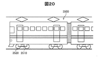
図20は、上記実施形態の電気機械装置を利用した鉄道車両を示す説明図である。この鉄道車両3500は、変速装置付モーター3510と、車輪3520とを有している。この変速装置付モーター3510は、車輪3520を駆動する。さらに、変速装置付モーター3510は、鉄道車両3500の制動時には発電機として利用され、電力が回生される。なお、変速装置付モーター3510としては、上述したエンコーダー付きの電気機械装置を用いても良い。
FIG. 20 is an explanatory diagram showing a railway vehicle using the electric machine device of the embodiment. The
図19及び図20の例から理解できるように、実施形態のエンコーダーを有する電気機械装置は、ロボットや、車両などの移動体を含む各種の装置に利用可能である。 As can be understood from the examples of FIGS. 19 and 20, the electromechanical device having the encoder of the embodiment can be used for various devices including a moving body such as a robot and a vehicle.
E.変形例:
なお、この発明は上記の実施例や実施形態に限られるものではなく、その要旨を逸脱しない範囲において種々の態様において実施することが可能であり、例えば次のような変形も可能である。
E. Variations:
The present invention is not limited to the above-described examples and embodiments, and can be implemented in various modes without departing from the gist thereof. For example, the following modifications are possible.
・変形例1:
上述した各種の実施形態では、エンコーダーに第1の磁石体と第2の磁石体の2つの磁石体を設けるものとしたが、いずれか一方の磁石体のみを設けるようにしてもよい。エンコーダーに1つの磁石体のみを設ける場合には、その磁石体の極数Mは偶数(2の倍数)とすることが好ましい。但し、2つの磁石体を設けるようにすれば、エンコーダーの回転体の絶対位置を検出できる点でより好ましい。
・ Modification 1:
In the various embodiments described above, the encoder is provided with the two magnet bodies of the first magnet body and the second magnet body. However, only one of the magnet bodies may be provided. When only one magnet body is provided in the encoder, the number M of poles of the magnet body is preferably an even number (a multiple of 2). However, it is more preferable that two magnet bodies are provided in that the absolute position of the rotary body of the encoder can be detected.
・変形例2:
上述した各種の実施形態では、直方体形状の小磁石111s,211sを利用していたが、この代わりに、強磁性薄膜を用いて小磁石111s,211sの少なくとも一方を形成してもよい。すなわち、強磁性薄膜をその厚みに磁化することによって、薄くて強力な磁石を形成することが可能である。強磁性薄膜を使用すれば、エンコーダーのサイズをよりコンパクトにすることが可能である。
In the various embodiments described above, the rectangular parallelepiped
・変形例3:
本願発明は、ロータリーエンコーダーのみに限らず、リニアエンコーダーにも適用可能である。
・ Modification 3:
The present invention can be applied not only to a rotary encoder but also to a linear encoder.
100A〜100F…ロータリーエンコーダー
110…第1の磁石体
111s…小磁石
111ps…小磁石ペア
112…被覆部材
120…第1のヨーク部材
130…第1の2軸磁気センサー回路
131,132…増幅回路
135…信号処理回路
140…基板
150…支持部材
160…磁気遮蔽部材
210…第2の磁石体
220…第2のヨーク部材
230…第2の2軸磁気センサー回路
300…位置信号生成部
400…回転体
500…電動モーター
522A,522B…電磁コイル
530…回転軸
600…制御部
610…主制御回路
620A,620B…駆動信号生成部
630A、630B…駆動回路
710…通信インターフェイス
720…データ受信部
730…位置信号生成部
740…角速度算出部
750…角加速度算出部
760…回転数算出部
762…アップダウンカウンター
763…ラッチ
770…回転数記憶部
780…入出力インターフェイス
790…レジスター
795…MPU
800…電池
3460…関節モーター
3470…把持部モーター
3480…アーム
3490…把持部
3500…鉄道車両
3510…変速装置付モーター
3520…車輪
DESCRIPTION OF
800 ...
Claims (12)
前記第2部材に設けられた複数の第1小磁石を含むM1極(M1は4以上の偶数)の第1磁石体と、
前記第2部材に設けられた複数の第2小磁石を含むM2極(M2は2以上の偶数)の第2磁石体と、
前記第1磁石体の表面から一定のギャップを有して前記第1部材上に配置された第1の2軸磁気センサー回路と、
前記第2磁石体の表面から一定のギャップを有して前記第1部材上に配置された第2の2軸磁気センサー回路と、
前記第1の2軸磁気センサー回路と前記第2の2軸磁気センサー回路の出力信号を処理する位置信号生成部と、
を備え、
前記第1の2軸磁気センサー回路と前記第2の2軸磁気センサー回路は、それぞれ2つの感磁軸方向を有し、
前記第1磁石体を構成する個々の第1小磁石は、前記第1の2軸磁気センサー回路の感磁面に交差する方向に磁化されており、
前記第2磁石体を構成する個々の第2小磁石は、前記第2の2軸磁気センサー回路の感磁面に交差する方向に磁化されており、
前記位置信号生成部は、前記第1の2軸磁気センサー回路の第1磁気角出力と、前記第2の2軸磁気センサー回路の第2磁気角出力とに応じて、前記第1部材に対する前記第2部材の位置を示す位置信号を生成する、エンコーダー。 An encoder that measures the position of a second member that moves along a predetermined direction of movement with respect to the first member,
A first magnet body having an M1 pole (M1 is an even number of 4 or more) including a plurality of first small magnets provided on the second member;
A second magnet body having M2 poles (M2 is an even number of 2 or more) including a plurality of second small magnets provided on the second member;
A first two-axis magnetic sensor circuit disposed on the first member with a certain gap from the surface of the first magnet body;
A second biaxial magnetic sensor circuit disposed on the first member with a certain gap from the surface of the second magnet body;
A position signal generator for processing output signals of the first two-axis magnetic sensor circuit and the second two-axis magnetic sensor circuit;
With
The first two-axis magnetic sensor circuit and the second two-axis magnetic sensor circuit each have two magnetosensitive axis directions,
Each of the first small magnets constituting the first magnet body is magnetized in a direction crossing the magnetic sensitive surface of the first two-axis magnetic sensor circuit,
Each of the second small magnets constituting the second magnet body is magnetized in a direction crossing the magnetic sensitive surface of the second biaxial magnetic sensor circuit,
The position signal generator is configured to output the first member with respect to the first member according to a first magnetic angle output of the first two-axis magnetic sensor circuit and a second magnetic angle output of the second two-axis magnetic sensor circuit. An encoder that generates a position signal indicating the position of the second member.
前記第1の2軸磁気センサー回路と前記第2の2軸磁気センサー回路のそれぞれは、互いに直交するX軸とY軸のうちの前記X軸に沿った磁場を測定するための複数個のX軸センサー素子と、前記Y軸に沿った磁場を測定するための複数個のY軸センサー素子と、を含む、エンコーダー。 The encoder according to claim 1,
Each of the first two-axis magnetic sensor circuit and the second two-axis magnetic sensor circuit includes a plurality of Xs for measuring a magnetic field along the X axis of the X axis and the Y axis orthogonal to each other. An encoder comprising an axis sensor element and a plurality of Y axis sensor elements for measuring a magnetic field along the Y axis.
前記整数M1,M2は、M1/2とM2/2が互いに素となる整数であり、
前記位置信号生成部は、前記第1の2軸磁気センサーの第1磁気角出力と前記第2の2軸磁気センサーの第2磁気角出力から前記位置信号を生成する、エンコーダー。 The encoder according to claim 1 or 2,
The integers M1 and M2 are integers in which M1 / 2 and M2 / 2 are relatively prime,
The position signal generation unit is an encoder that generates the position signal from a first magnetic angle output of the first two-axis magnetic sensor and a second magnetic angle output of the second two-axis magnetic sensor.
前記整数M1は、2Q+1(Qは1以上の整数)に等しく、
前記整数M2は、2に等しく、
前記第1の2軸磁気センサー回路の第1磁気角出力は、前記第1部材に対する前記第2部材の相対位置を示すN1ビット(N1は2以上の整数)のデジタル信号であり、
前記第2の2軸磁気センサー回路の第2磁気角出力は、前記第1部材に対する前記第2部材の相対位置を示すN2ビット(N2は2以上の整数)のデジタル信号であり、
前記位置信号生成部は、前記第2磁気角出力の最上位Qビットを最上位に配置するとともに、前記第1磁気角出力のN1ビットを前記第2磁気角出力の前記最上位Qビットの下に配置した(N1+Q)ビットの信号を前記位置信号として生成する、エンコーダー。 The encoder according to claim 3, wherein
The integer M1 is equal to 2 Q + 1 (Q is an integer of 1 or more),
The integer M2 is equal to 2,
The first magnetic angle output of the first two-axis magnetic sensor circuit is a digital signal of N1 bits (N1 is an integer of 2 or more) indicating a relative position of the second member with respect to the first member.
The second magnetic angle output of the second two-axis magnetic sensor circuit is a digital signal of N2 bits (N2 is an integer of 2 or more) indicating the relative position of the second member with respect to the first member,
The position signal generation unit arranges the most significant Q bit of the second magnetic angle output at the most significant position, and sets the N1 bit of the first magnetic angle output below the most significant Q bit of the second magnetic angle output. An encoder that generates a signal of (N1 + Q) bits arranged in the position signal as the position signal.
前記位置信号生成部は、
前記第2の部材の移動に応じて前記第1の2軸磁気センサー回路の前記第1磁気角出力と前記第2の2軸磁気センサー回路の前記第2磁気角出力とがともに増加する際に、前記第1磁気角出力が前記第1磁気角出力の最大値から最小値に戻るタイミングと、前記第2磁気角出力の前記最上位Qビットがインクリメントするタイミングとが一致するように、前記第1磁気角出力に応じて前記第2磁気角出力の前記最上位Qビットを補正し、
前記補正後の前記第2磁気角出力の前記最上位Qビットを用いて、前記(N1+Q)ビットの前記位置信号を生成する、
エンコーダー。 The encoder according to claim 4, wherein
The position signal generator is
When the first magnetic angle output of the first two-axis magnetic sensor circuit and the second magnetic angle output of the second two-axis magnetic sensor circuit both increase in accordance with the movement of the second member. The timing at which the first magnetic angle output returns from the maximum value of the first magnetic angle output to the minimum value coincides with the timing at which the most significant Q bit of the second magnetic angle output is incremented. Correcting the most significant Q bit of the second magnetic angle output according to one magnetic angle output;
Generating the position signal of the (N1 + Q) bits using the most significant Q bits of the corrected second magnetic angle output;
encoder.
前記第2部材は、回転体であり、
前記第1磁石体は、互いに逆方向に磁化された2つの第1小磁石によって構成された小磁石ペアを複数組含み、
前記複数組の小磁石ペアは、前記回転体の回転軸廻りの円形の軌道に沿って配置されている、エンコーダー。 The encoder according to any one of claims 1 to 5,
The second member is a rotating body,
The first magnet body includes a plurality of small magnet pairs configured by two first small magnets magnetized in opposite directions to each other,
The plurality of small magnet pairs are arranged along a circular orbit around a rotation axis of the rotating body.
個々の第1小磁石は、直方体形状を有し、
各小磁石ペアは、2つの第1小磁石と、前記2つの第1小磁石の周囲の少なくとも一部を被覆することによって前記小磁石ペアの全体の形状を等辺台形柱形状とする被覆部材と、を有する、エンコーダー。 The encoder according to claim 6, wherein
Each first small magnet has a rectangular parallelepiped shape,
Each small magnet pair includes two first small magnets and a covering member that covers at least a part of the periphery of the two first small magnets so that the entire shape of the small magnet pair is an isosceles trapezoidal columnar shape. , Having an encoder.
前記第1小磁石と前記第2小磁石の少なくとも一方は、強磁性薄膜によって形成されている、エンコーダー。 The encoder according to any one of claims 1 to 6,
An encoder in which at least one of the first small magnet and the second small magnet is formed of a ferromagnetic thin film.
前記電気機械装置のローターに接続された請求項1〜7のいずれか一項に記載のエンコーダーと、
前記電気機械装置の動作を制御する制御部と、
を備える、電気機械装置。 An electromechanical device,
The encoder according to any one of claims 1 to 7, connected to a rotor of the electromechanical device;
A control unit for controlling the operation of the electromechanical device;
An electromechanical device comprising:
前記電気機械装置は、2相の電磁コイルを有する2相ACブラシレスモーターであり、
前記制御部は、前記エンコーダーの前記第1の2軸磁気センサー回路から出力される前記正弦波信号及び前記余弦波信号から、前記2相の電磁コイルの駆動信号を生成する駆動信号生成部を有する、電気機械装置。 An electromechanical device according to claim 9,
The electromechanical device is a two-phase AC brushless motor having a two-phase electromagnetic coil;
The control unit includes a drive signal generation unit that generates a drive signal for the two-phase electromagnetic coil from the sine wave signal and the cosine wave signal output from the first two-axis magnetic sensor circuit of the encoder. , Electromechanical devices.
Priority Applications (3)
| Application Number | Priority Date | Filing Date | Title |
|---|---|---|---|
| JP2014053242A JP2015175762A (en) | 2014-03-17 | 2014-03-17 | Encoder, electromechanical device, robot, and railway vehicle |
| CN201510111581.0A CN104931075A (en) | 2014-03-17 | 2015-03-13 | Encoder, electromechanical device, robot and railway vehicle |
| CN201510119278.5A CN104931076A (en) | 2014-03-17 | 2015-03-13 | Encoder, electromechanical device, robot and railway vehicle |
Applications Claiming Priority (1)
| Application Number | Priority Date | Filing Date | Title |
|---|---|---|---|
| JP2014053242A JP2015175762A (en) | 2014-03-17 | 2014-03-17 | Encoder, electromechanical device, robot, and railway vehicle |
Publications (2)
| Publication Number | Publication Date |
|---|---|
| JP2015175762A true JP2015175762A (en) | 2015-10-05 |
| JP2015175762A5 JP2015175762A5 (en) | 2017-03-30 |
Family
ID=54255069
Family Applications (1)
| Application Number | Title | Priority Date | Filing Date |
|---|---|---|---|
| JP2014053242A Ceased JP2015175762A (en) | 2014-03-17 | 2014-03-17 | Encoder, electromechanical device, robot, and railway vehicle |
Country Status (1)
| Country | Link |
|---|---|
| JP (1) | JP2015175762A (en) |
Cited By (3)
| Publication number | Priority date | Publication date | Assignee | Title |
|---|---|---|---|---|
| JP2017090241A (en) * | 2015-11-10 | 2017-05-25 | 東洋電装株式会社 | Rotation angle detection sensor |
| JP2019521362A (en) * | 2016-07-22 | 2019-07-25 | シーエムアール サージカル リミテッドCmr Surgical Limited | Position detection device and assembling method thereof |
| JP2019143991A (en) * | 2018-02-16 | 2019-08-29 | Tdk株式会社 | Magnetic sensor system and magnetic scale |
Citations (11)
| Publication number | Priority date | Publication date | Assignee | Title |
|---|---|---|---|---|
| JPH01110085A (en) * | 1987-10-21 | 1989-04-26 | Canon Inc | Motor controller |
| JPH0295209A (en) * | 1988-09-30 | 1990-04-06 | Yokogawa Electric Corp | Multiple rotation absolute encoder |
| JPH06117874A (en) * | 1992-10-05 | 1994-04-28 | Tokin Corp | Pulse generator |
| JPH07134047A (en) * | 1993-11-11 | 1995-05-23 | Nikon Corp | Multiple-rotation encoder |
| JPH07243867A (en) * | 1994-03-07 | 1995-09-19 | Teijin Seiki Co Ltd | Magnetic scale, and magnet detector with the magnetic scale |
| JP2003086420A (en) * | 2001-09-11 | 2003-03-20 | Koyo Seiko Co Ltd | Pulser ring |
| JP2008128961A (en) * | 2006-11-24 | 2008-06-05 | Alps Electric Co Ltd | Absolute angle detector |
| JP2010233441A (en) * | 2009-03-05 | 2010-10-14 | Seiko Epson Corp | Energy conversion apparatus, and electro-mechanic apparatus |
| JP2012112707A (en) * | 2010-11-22 | 2012-06-14 | Nidec Sankyo Corp | Rotary encoder |
| JP2014044218A (en) * | 2008-08-26 | 2014-03-13 | Nikon Corp | Encoder system and signal processing method |
| JP2015004630A (en) * | 2013-06-24 | 2015-01-08 | 大同特殊鋼株式会社 | Magnetic type movement detection device |
-
2014
- 2014-03-17 JP JP2014053242A patent/JP2015175762A/en not_active Ceased
Patent Citations (11)
| Publication number | Priority date | Publication date | Assignee | Title |
|---|---|---|---|---|
| JPH01110085A (en) * | 1987-10-21 | 1989-04-26 | Canon Inc | Motor controller |
| JPH0295209A (en) * | 1988-09-30 | 1990-04-06 | Yokogawa Electric Corp | Multiple rotation absolute encoder |
| JPH06117874A (en) * | 1992-10-05 | 1994-04-28 | Tokin Corp | Pulse generator |
| JPH07134047A (en) * | 1993-11-11 | 1995-05-23 | Nikon Corp | Multiple-rotation encoder |
| JPH07243867A (en) * | 1994-03-07 | 1995-09-19 | Teijin Seiki Co Ltd | Magnetic scale, and magnet detector with the magnetic scale |
| JP2003086420A (en) * | 2001-09-11 | 2003-03-20 | Koyo Seiko Co Ltd | Pulser ring |
| JP2008128961A (en) * | 2006-11-24 | 2008-06-05 | Alps Electric Co Ltd | Absolute angle detector |
| JP2014044218A (en) * | 2008-08-26 | 2014-03-13 | Nikon Corp | Encoder system and signal processing method |
| JP2010233441A (en) * | 2009-03-05 | 2010-10-14 | Seiko Epson Corp | Energy conversion apparatus, and electro-mechanic apparatus |
| JP2012112707A (en) * | 2010-11-22 | 2012-06-14 | Nidec Sankyo Corp | Rotary encoder |
| JP2015004630A (en) * | 2013-06-24 | 2015-01-08 | 大同特殊鋼株式会社 | Magnetic type movement detection device |
Cited By (4)
| Publication number | Priority date | Publication date | Assignee | Title |
|---|---|---|---|---|
| JP2017090241A (en) * | 2015-11-10 | 2017-05-25 | 東洋電装株式会社 | Rotation angle detection sensor |
| JP2019521362A (en) * | 2016-07-22 | 2019-07-25 | シーエムアール サージカル リミテッドCmr Surgical Limited | Position detection device and assembling method thereof |
| JP6990231B2 (en) | 2016-07-22 | 2022-01-12 | シーエムアール サージカル リミテッド | Position detector and its assembly method |
| JP2019143991A (en) * | 2018-02-16 | 2019-08-29 | Tdk株式会社 | Magnetic sensor system and magnetic scale |
Similar Documents
| Publication | Publication Date | Title |
|---|---|---|
| JP2015114209A (en) | Encoder and electric machinery | |
| TWI579533B (en) | Absolute encoder devices and motors | |
| JP6477933B2 (en) | Rotation angle detection device and rotation angle detection method | |
| CN104931075A (en) | Encoder, electromechanical device, robot and railway vehicle | |
| JP6484008B2 (en) | Encoder and rotation angle position calculation method | |
| JP2015114209A5 (en) | ||
| JPWO2007055135A1 (en) | Magnetic encoder device | |
| JP2020153806A (en) | Rotation angle detector | |
| JP5545121B2 (en) | Rotation angle / torque sensor | |
| JP2012042352A (en) | Rotation angle and torque sensor | |
| JP5201493B2 (en) | Position detection device and linear drive device | |
| JP2015175762A (en) | Encoder, electromechanical device, robot, and railway vehicle | |
| JP5802297B2 (en) | Motion detection device | |
| JP2018197737A (en) | Angle detector, relative angle detector, torque sensor, electrically-driven power steering device, and vehicle | |
| JP5511748B2 (en) | Motion detection device | |
| JP4900838B2 (en) | Position detection device and linear drive device | |
| JP2015114208A (en) | Encoder and electric machinery | |
| JP2015061411A (en) | Linear/rotary actuator and method for controlling the same | |
| JP6791013B2 (en) | Two-axis integrated motor | |
| JP2015175760A (en) | Encoder, electromechanical device, robot, and railway vehicle | |
| JP2005315696A (en) | Apparatus for detecting rotation angle of rotating body | |
| JP2015175762A5 (en) | ||
| JP2018048870A (en) | Rotation angle detector | |
| JP6525846B2 (en) | Resolver | |
| WO2024090210A1 (en) | Multi-rotation angle detection device and segment counter for same |
Legal Events
| Date | Code | Title | Description |
|---|---|---|---|
| A711 | Notification of change in applicant |
Free format text: JAPANESE INTERMEDIATE CODE: A711 Effective date: 20160907 |
|
| RD03 | Notification of appointment of power of attorney |
Free format text: JAPANESE INTERMEDIATE CODE: A7423 Effective date: 20161028 |
|
| RD04 | Notification of resignation of power of attorney |
Free format text: JAPANESE INTERMEDIATE CODE: A7424 Effective date: 20161031 |
|
| A521 | Request for written amendment filed |
Free format text: JAPANESE INTERMEDIATE CODE: A523 Effective date: 20170223 |
|
| A621 | Written request for application examination |
Free format text: JAPANESE INTERMEDIATE CODE: A621 Effective date: 20170223 |
|
| A977 | Report on retrieval |
Free format text: JAPANESE INTERMEDIATE CODE: A971007 Effective date: 20171120 |
|
| A01 | Written decision to grant a patent or to grant a registration (utility model) |
Free format text: JAPANESE INTERMEDIATE CODE: A01 Effective date: 20171128 |
|
| A045 | Written measure of dismissal of application [lapsed due to lack of payment] |
Free format text: JAPANESE INTERMEDIATE CODE: A045 Effective date: 20180327 |