JP2015174648A - Operation input device, and operation input method - Google Patents
Operation input device, and operation input method Download PDFInfo
- Publication number
- JP2015174648A JP2015174648A JP2014055261A JP2014055261A JP2015174648A JP 2015174648 A JP2015174648 A JP 2015174648A JP 2014055261 A JP2014055261 A JP 2014055261A JP 2014055261 A JP2014055261 A JP 2014055261A JP 2015174648 A JP2015174648 A JP 2015174648A
- Authority
- JP
- Japan
- Prior art keywords
- frequency
- movement amount
- driver
- movement
- signal
- Prior art date
- Legal status (The legal status is an assumption and is not a legal conclusion. Google has not performed a legal analysis and makes no representation as to the accuracy of the status listed.)
- Pending
Links
- 238000000034 method Methods 0.000 title claims description 54
- 230000002238 attenuated effect Effects 0.000 claims abstract description 25
- 238000001514 detection method Methods 0.000 claims description 15
- 230000007274 generation of a signal involved in cell-cell signaling Effects 0.000 claims description 11
- 230000004048 modification Effects 0.000 description 24
- 238000012986 modification Methods 0.000 description 24
- 230000001133 acceleration Effects 0.000 description 3
- 230000005057 finger movement Effects 0.000 description 3
- 238000013016 damping Methods 0.000 description 2
- 230000006870 function Effects 0.000 description 2
- 241000145347 Balssiathelphusa cursor Species 0.000 description 1
- 239000012141 concentrate Substances 0.000 description 1
- 238000007796 conventional method Methods 0.000 description 1
- 230000003111 delayed effect Effects 0.000 description 1
- 238000010586 diagram Methods 0.000 description 1
- 238000009499 grossing Methods 0.000 description 1
- 239000004973 liquid crystal related substance Substances 0.000 description 1
- 230000004044 response Effects 0.000 description 1
Images


Classifications
-
- G—PHYSICS
- G06—COMPUTING; CALCULATING OR COUNTING
- G06F—ELECTRIC DIGITAL DATA PROCESSING
- G06F3/00—Input arrangements for transferring data to be processed into a form capable of being handled by the computer; Output arrangements for transferring data from processing unit to output unit, e.g. interface arrangements
- G06F3/01—Input arrangements or combined input and output arrangements for interaction between user and computer
- G06F3/03—Arrangements for converting the position or the displacement of a member into a coded form
- G06F3/033—Pointing devices displaced or positioned by the user, e.g. mice, trackballs, pens or joysticks; Accessories therefor
- G06F3/038—Control and interface arrangements therefor, e.g. drivers or device-embedded control circuitry
- G06F3/0383—Signal control means within the pointing device
-
- B—PERFORMING OPERATIONS; TRANSPORTING
- B60—VEHICLES IN GENERAL
- B60K—ARRANGEMENT OR MOUNTING OF PROPULSION UNITS OR OF TRANSMISSIONS IN VEHICLES; ARRANGEMENT OR MOUNTING OF PLURAL DIVERSE PRIME-MOVERS IN VEHICLES; AUXILIARY DRIVES FOR VEHICLES; INSTRUMENTATION OR DASHBOARDS FOR VEHICLES; ARRANGEMENTS IN CONNECTION WITH COOLING, AIR INTAKE, GAS EXHAUST OR FUEL SUPPLY OF PROPULSION UNITS IN VEHICLES
- B60K35/00—Instruments specially adapted for vehicles; Arrangement of instruments in or on vehicles
- B60K35/10—Input arrangements, i.e. from user to vehicle, associated with vehicle functions or specially adapted therefor
-
- B—PERFORMING OPERATIONS; TRANSPORTING
- B60—VEHICLES IN GENERAL
- B60K—ARRANGEMENT OR MOUNTING OF PROPULSION UNITS OR OF TRANSMISSIONS IN VEHICLES; ARRANGEMENT OR MOUNTING OF PLURAL DIVERSE PRIME-MOVERS IN VEHICLES; AUXILIARY DRIVES FOR VEHICLES; INSTRUMENTATION OR DASHBOARDS FOR VEHICLES; ARRANGEMENTS IN CONNECTION WITH COOLING, AIR INTAKE, GAS EXHAUST OR FUEL SUPPLY OF PROPULSION UNITS IN VEHICLES
- B60K35/00—Instruments specially adapted for vehicles; Arrangement of instruments in or on vehicles
- B60K35/80—Arrangements for controlling instruments
- B60K35/81—Arrangements for controlling instruments for controlling displays
-
- G—PHYSICS
- G06—COMPUTING; CALCULATING OR COUNTING
- G06F—ELECTRIC DIGITAL DATA PROCESSING
- G06F3/00—Input arrangements for transferring data to be processed into a form capable of being handled by the computer; Output arrangements for transferring data from processing unit to output unit, e.g. interface arrangements
- G06F3/01—Input arrangements or combined input and output arrangements for interaction between user and computer
- G06F3/03—Arrangements for converting the position or the displacement of a member into a coded form
- G06F3/033—Pointing devices displaced or positioned by the user, e.g. mice, trackballs, pens or joysticks; Accessories therefor
- G06F3/0354—Pointing devices displaced or positioned by the user, e.g. mice, trackballs, pens or joysticks; Accessories therefor with detection of 2D relative movements between the device, or an operating part thereof, and a plane or surface, e.g. 2D mice, trackballs, pens or pucks
- G06F3/03547—Touch pads, in which fingers can move on a surface
-
- B—PERFORMING OPERATIONS; TRANSPORTING
- B60—VEHICLES IN GENERAL
- B60K—ARRANGEMENT OR MOUNTING OF PROPULSION UNITS OR OF TRANSMISSIONS IN VEHICLES; ARRANGEMENT OR MOUNTING OF PLURAL DIVERSE PRIME-MOVERS IN VEHICLES; AUXILIARY DRIVES FOR VEHICLES; INSTRUMENTATION OR DASHBOARDS FOR VEHICLES; ARRANGEMENTS IN CONNECTION WITH COOLING, AIR INTAKE, GAS EXHAUST OR FUEL SUPPLY OF PROPULSION UNITS IN VEHICLES
- B60K2360/00—Indexing scheme associated with groups B60K35/00 or B60K37/00 relating to details of instruments or dashboards
- B60K2360/143—Touch sensitive instrument input devices
-
- B—PERFORMING OPERATIONS; TRANSPORTING
- B60—VEHICLES IN GENERAL
- B60K—ARRANGEMENT OR MOUNTING OF PROPULSION UNITS OR OF TRANSMISSIONS IN VEHICLES; ARRANGEMENT OR MOUNTING OF PLURAL DIVERSE PRIME-MOVERS IN VEHICLES; AUXILIARY DRIVES FOR VEHICLES; INSTRUMENTATION OR DASHBOARDS FOR VEHICLES; ARRANGEMENTS IN CONNECTION WITH COOLING, AIR INTAKE, GAS EXHAUST OR FUEL SUPPLY OF PROPULSION UNITS IN VEHICLES
- B60K2360/00—Indexing scheme associated with groups B60K35/00 or B60K37/00 relating to details of instruments or dashboards
- B60K2360/146—Instrument input by gesture
- B60K2360/1468—Touch gesture
Landscapes
- Engineering & Computer Science (AREA)
- Chemical & Material Sciences (AREA)
- Combustion & Propulsion (AREA)
- Transportation (AREA)
- Mechanical Engineering (AREA)
- General Engineering & Computer Science (AREA)
- Theoretical Computer Science (AREA)
- Human Computer Interaction (AREA)
- Physics & Mathematics (AREA)
- General Physics & Mathematics (AREA)
- User Interface Of Digital Computer (AREA)
- Position Input By Displaying (AREA)
Abstract
Description
本発明は、車両の運転者による操作を受け付けることで、所定の情報を入力する技術に関する。 The present invention relates to a technique for inputting predetermined information by receiving an operation by a vehicle driver.
近年の車両には、楽曲を再生するオーディオシステムや行き先を案内するナビゲーションシステム等の種々のシステムが搭載されており、これらのシステムの中には運転者の手または指の移動量を反映させて、目盛りの調節や画面上のカーソル移動を行うものがある。例えば、オーディオシステムであれば、ダイヤル式の操作部への回転操作が行われると該回転操作の操作量に応じた音量(目盛り)への調節が行われ、ナビゲーションシステムであれば、タッチパッド上で指のスライド操作が行われると該スライド操作の操作量に応じて表示画面上の行き先選択用のカーソルを移動させる。
もっとも、車両内では、運転者の手または指の動きは車両の振動などの外乱因子によってガタガタした動きとなることがあり、目盛りの調節や画面上のカーソル移動も不安定になってしまう場合がある。例えば、上述の回転操作の操作量が不安定であるために所望の音量に調節することが困難な場合や、上述のスライド操作の操作量が不安定であるためにカーソルの位置が定まらない場合等がある。
Recent vehicles are equipped with various systems such as an audio system that plays music and a navigation system that guides the destination, and these systems reflect the amount of movement of the driver's hands or fingers. , There are things that adjust the scale and move the cursor on the screen. For example, in the case of an audio system, when a rotary operation to a dial-type operation unit is performed, the volume (scale) is adjusted according to the operation amount of the rotation operation, and in the case of a navigation system, the volume on the touch pad is adjusted. When the finger slide operation is performed, the destination selection cursor on the display screen is moved according to the operation amount of the slide operation.
However, in the vehicle, the movement of the driver's hand or finger may be rattling due to disturbance factors such as vehicle vibration, and the adjustment of the scale and movement of the cursor on the screen may become unstable. is there. For example, when the operation amount of the rotation operation described above is unstable, it is difficult to adjust to a desired volume, or when the position of the cursor cannot be determined because the operation amount of the slide operation described above is unstable Etc.
そこで、目盛りの調節やカーソルの移動がガタガタした動きとなる原因の外乱成分を、ローパスフィルターを用いて除去することで、目盛りの調節やカーソル移動を滑らかにする技術が提案されている(特許文献1)。 In view of this, a technique has been proposed for smoothing the adjustment of the scale and the movement of the cursor by removing a disturbance component that causes the movement of the scale and the movement of the cursor to be rattling using a low-pass filter (Patent Document). 1).
しかし、提案の技術では、目盛りの調節やカーソルの移動が滑らかになるものの、運転者が手または指を動かしたときの反応が一瞬遅れるような違和感を与えるという問題があった。 However, the proposed technique has a problem that although the adjustment of the scale and the movement of the cursor are smooth, there is a sense of incongruity that the response when the driver moves the hand or finger is delayed for a moment.
この発明は、従来の技術が有する上述した課題に鑑みてなされたものであり、外乱因子の入力結果への影響を抑制すると共に、運転者の違和感を抑制する技術の提供を目的とする。 The present invention has been made in view of the above-described problems of conventional techniques, and an object of the present invention is to provide a technique that suppresses the influence of disturbance factors on the input result and suppresses the driver's uncomfortable feeling.
上述した課題を解決するために、本発明の操作入力装置は、運転者の手または指の移動量を検出して、該移動量の時系列信号を生成する。そして、時系列信号中に含まれる信号成分の中で、所定の第1周波数から該第1周波数よりも高い所定の第2周波数までの信号成分を減衰させて、この信号成分が減衰された時系列信号に基づいて運転者の入力操作を受け付ける。 In order to solve the above-described problem, the operation input device of the present invention detects the amount of movement of the driver's hand or finger and generates a time-series signal of the amount of movement. When a signal component from a predetermined first frequency to a predetermined second frequency higher than the first frequency is attenuated among the signal components included in the time series signal, the signal component is attenuated. A driver's input operation is received based on the series signal.
このような本発明の操作入力装置によると、車両の振動などの外乱因子(ガタガタした動き)に対応する「第1周波数から第2周波数までの信号成分」が減衰された時系列信号に基づいて入力操作を受け付けるので、外乱因子の影響が抑制された滑らかな入力を行わせることができる。また、「第2周波数より高い信号成分」が減衰されていない時系列信号に基づいて入力操作を受け付けるので、「帯域減衰フィルター通過前の移動量信号」に対する「帯域減衰フィルター通過後の移動量信号」の立ち上がりの遅延を小さく抑えることができる。このため、手または指の移動(動き)に情報の入力が追随するまでの時間を小さくすることができ、運転者の違和感を抑制することが可能となる。 According to such an operation input device of the present invention, based on a time-series signal in which “a signal component from the first frequency to the second frequency” corresponding to a disturbance factor such as vibration of the vehicle (a rattling motion) is attenuated. Since the input operation is accepted, it is possible to perform a smooth input in which the influence of the disturbance factor is suppressed. In addition, since the input operation is accepted based on the time series signal in which “the signal component higher than the second frequency” is not attenuated, the “movement amount signal after passing through the band attenuation filter” with respect to the “movement amount signal before passing through the band attenuation filter” ”Can be suppressed to a small delay. For this reason, it is possible to reduce the time until the input of information follows the movement (movement) of the hand or finger, and to suppress the driver's uncomfortable feeling.
以下では、上述した本願発明の内容を明確にするために操作入力装置の実施例について説明する。
A.装置構成 :
図1には、車両に設けられた操作入力装置10の構成が示されている。本実施例の操作入力装置10では、制御装置11が、タッチパッド12をなぞる(タッチパッド12上を移動する)運転者の指の移動量に基づいて、表示部13上のカーソルを移動させながら表示(移動表示)する。例えば、図2に示すように、ナビゲーションシステムにおいて表示部13に行き先選択画面(ここでは五十音の行)を表示している状態で、タッチパッド12をなぞる運転者の指の移動量に基づいて、カーソルを移動表示する。
図1に示す制御装置11は、CPUやメモリ、各種コントローラー等が搭載された基板を有しており、運転席前方のインストルメントパネルの奥側に設置されている。また、タッチパッド12は、運転席隣のセンターコンソールに設けられ、タッチパッド12上における指の座標位置を検出して該座標位置を示す指位置信号を制御装置11に出力する。また、表示部13は、インストルメントパネルに設けられた液晶表示器から構成され、制御装置11に指示された位置にカーソルを表示する。
尚、タッチパッド12としては、静電容量方式や感圧方式のもの等を採用することができる。また、表示部13としては、フロントガラス(ウインドシールド)に表示内容を投影するヘッドアップディスプレイ等を採用してもよい。
また、本実施例では、制御装置11への入力装置としてタッチパッド12が用いられた場合が示されているが、これに限られるものではなく、例えば、空中での指の動き(あるいは手の動きなど)を、カメラの画像を解析するなどの方法によって検出して、検出した動きを制御装置11に対する入力として用いることも可能である。
Hereinafter, embodiments of the operation input device will be described in order to clarify the contents of the present invention described above.
A. Device configuration :
FIG. 1 shows a configuration of an
The
As the
In the present embodiment, the case where the
制御装置11内部をそれぞれの機能を有する機能ブロックに分類すると、制御装置11は、タッチパッド12からの指位置信号に基づき運転者の指の移動量を検出し、該移動量の時系列信号(以下「移動量信号」という)を生成する移動量信号生成部14、移動量信号生成部14が生成した移動量信号の中周波成分(所定の第1周波数から所定の第2周波数までの信号成分)を減衰させる帯域減衰フィルター15、帯域減衰フィルター15を通過した移動量信号に基づいて運転者の入力操作を受け付けて表示部13上のカーソルの表示制御を行う表示制御部16を備えている。
When the inside of the
尚、移動量信号生成部14が本発明における「時系列信号生成手段」に対応し、帯域減衰フィルター15が本発明における「帯域減衰フィルター」に対応し、表示制御部16が本発明における「入力操作受付手段」に対応している。
The movement amount
以下では、上述したような操作入力装置10において行われる「カーソル表示処理」について説明する。このカーソル表示処理では、タッチパッド12をなぞる(タッチパッド12上を移動する)運転者の指の移動量に基づいて、表示部13にカーソルを表示する処理が行われる。
Hereinafter, the “cursor display process” performed in the
B.カーソル表示処理 :
図3には、本実施例の操作入力装置10において行われるカーソル表示処理のフローチャートが示されている。尚、このカーソル表示処理は、実際には、制御装置11内部のCPUがROMに記憶されたプログラムを実行することによって行われるが、以下では、制御装置11または上述した機能ブロック14〜16を実行主体として説明する。また、カーソル表示処理は、タイマ割り込み処理として一定の時間毎に(例えば4m秒毎に)行われる。
B. Cursor display processing:
FIG. 3 shows a flowchart of cursor display processing performed in the
図3に示すように、カーソル表示処理を開始すると先ず、制御装置11の移動量信号生成部14が、タッチパッド12のタッチ位置情報を検出する処理を行う(S100)。タッチ位置情報とは、タッチパッド12上における指の座標位置(X座標,Y座標)を示す情報である。S100の処理の結果、タッチ位置情報が検出されなければ(S102:no)、そのまま図2に示すカーソル表示処理を終了する。すなわち、タッチ位置情報が検出されないということは、タッチパッド12上に指が存在しない(置かれていない)ということであるので、この場合は、カーソルを移動させる処理は行わないまま、カーソル表示処理を終了する(カーソルは前回の表示位置に表示したままにする)。
As shown in FIG. 3, when the cursor display process is started, first, the movement amount
これに対して、タッチ位置情報が検出された場合、すなわち、タッチパッド12上に指が存在する(置かれている)場合は(S102:yes)、図2のカーソル表示処理を前回実行してからの(例えば4m秒前からの)指の移動量を算出する(S104)。この算出処理は、今回のS100の処理で検出されたタッチ位置情報が示す座標位置と、前回のS100の処理で検出されたタッチ位置情報が示す座標位置との差分(X方向,Y方向への差分)を算出することにより行う。例えば、前回のS100の処理で検出されたタッチ位置情報がX座標100,Y座標200を示す情報であり、今回のS100の処理で検出された位置情報がX座標110,Y座標215を示す情報であれば、X座標同士の差分「110−100=10」をX方向への移動量として算出し、Y座標同士の差分「215−200=15」をY方向への移動量として算出する。図3に示すカーソル表示処理がタイマ割り込みで実行されるたびに、S104の処理で移動量が算出されて該移動量が帯域減衰フィルター15に出力されることによって、移動量の時系列信号(移動量信号)が生成される。
尚、S104の処理では、前回のカーソル表示処理におけるS100の処理でタッチ位置情報が検出されてなければ移動量は「0(X方向への移動量0、Y方向への移動量0)」とする。すなわち、本実施例の操作入力装置10では、S104の処理で算出した移動量に基づいて表示部13上のカーソルを移動させるので、タッチパッド12上に指がおかれた瞬間にカーソルが移動するのを防止すべく、前回のカーソル表示処理におけるS100の処理でタッチ位置情報が検出されてなければ(タッチパッド12上に指がおかれた瞬間は)移動量は「0」とする。
On the other hand, when the touch position information is detected, that is, when a finger is present (placed) on the touch pad 12 (S102: yes), the cursor display process of FIG. The movement amount of the finger from (for example, 4 ms before) is calculated (S104). In this calculation process, the difference between the coordinate position indicated by the touch position information detected in the current process of S100 and the coordinate position indicated by the touch position information detected in the previous process of S100 (in the X direction and the Y direction). (Difference) is calculated. For example, the touch position information detected in the previous process of S100 is information indicating the X coordinate 100 and the Y coordinate 200, and the position information detected in the current process of S100 is information indicating the X coordinate 110 and the Y coordinate 215. If so, the difference “110−100 = 10” between the X coordinates is calculated as the movement amount in the X direction, and the difference “215−200 = 15” between the Y coordinates is calculated as the movement amount in the Y direction. Each time the cursor display process shown in FIG. 3 is executed by a timer interrupt, the movement amount is calculated in the process of S104, and the movement amount is output to the
In the process of S104, if the touch position information is not detected in the process of S100 in the previous cursor display process, the movement amount is “0 (
こうして、タッチパッド12上における指の移動量を算出したら(S104)、移動量信号生成部14は、該移動量を帯域減衰フィルター15に向けて出力することで、移動量信号を生成する。そして、帯域減衰フィルター15は、移動量信号にデジタルフィルター処理を施す(S106)。図4には、帯域減衰フィルター15のデジタルフィルター処理によって減衰される周波数帯域が例示されている。図4に示すように、帯域減衰フィルター15は、移動量信号にデジタルフィルター処理を施すことによって、移動量信号の10Hz(第1周波数)から30Hz(第2周波数)までの信号成分を減衰させる。すなわち、帯域減衰フィルター15は、移動量信号の10Hzより低い信号成分(低周波成分)および30Hzより高い信号成分(高周波成分)は減衰させずに通過させ、10Hzから30Hzまでの信号成分(中周波成分)は減衰させる。尚、移動量信号にデジタルフィルター処理を施す理由については後述する。
Thus, when the movement amount of the finger on the
こうして、移動量信号にデジタルフィルター処理を施したら(S106)、制御装置11の表示制御部16は、デジタルフィルター処理が施された移動量信号、すなわち、中周波成分が減衰された移動量信号(主に移動量信号の低周波成分および高周波成分)に基づいて表示部13上のカーソルを移動させて表示(移動表示)する。つまり、移動量信号は、運転者の指のタッチパッド12上における移動量に対応する信号であることから、この移動量に対応する画素数分だけ移動した位置にカーソルを表示する(S108)。こうして、カーソルを表示したら、図3に示すカーソル表示処理を終了する。当然ながら、このカーソル表示処理は、次のタイマ割り込みのタイミングで再び起動される。
Thus, when the digital filter processing is performed on the movement amount signal (S106), the
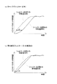
ここで、上述したS106の処理において、移動量信号にデジタルフィルター処理を施す理由について説明する。図5(a)には、デジタルフィルター処理が施される前の移動量信号(デジタルフィルター処理前の移動量信号)が破線で示され、従来のデジタルフィルター処理が施された後の移動量信号、すなわち、ローパスフィルターによって中周波成分および高周波成分が減衰された移動量信号(移動量信号の低周波成分)が実線で示されている。図5(a)に示すように、従来のデジタルフィルター処理が施された場合は、デジタルフィルター処理前の移動量信号から、車体の振動などの外乱因子によるガタガタした動き(外乱因子に対応する中周波成分)が減衰されて、滑らかな移動量信号となっている。従って、このような移動量信号に基づいてカーソルが表示された場合は、カーソルは外乱因子の影響を受けることなく(ふらつくことなく)滑らかに移動表示されることとなる。 Here, the reason for applying the digital filter process to the movement amount signal in the process of S106 described above will be described. In FIG. 5A, the movement amount signal before the digital filter processing (movement amount signal before the digital filter processing) is indicated by a broken line, and the movement amount signal after the conventional digital filter processing is performed. That is, the movement amount signal (low frequency component of the movement amount signal) in which the medium frequency component and the high frequency component are attenuated by the low-pass filter is indicated by a solid line. As shown in FIG. 5A, when the conventional digital filter processing is performed, the movement signal before the digital filter processing causes a rattling movement caused by a disturbance factor such as a vibration of the vehicle body (a medium corresponding to the disturbance factor). (Frequency component) is attenuated to form a smooth movement amount signal. Therefore, when the cursor is displayed based on such a movement amount signal, the cursor is smoothly displayed without being affected by the disturbance factor (without wobbling).
これに対して、図5(b)には、デジタルフィルター処理が施される前の移動量信号が破線で示され、本実施例のデジタルフィルター処理が施された後の移動量信号、すなわち、帯域減衰フィルター15によって中周波成分が減衰された移動量信号(移動量信号の低周波成分および高周波成分)が実線で示されている。図5(b)に示すように、本実施例のデジタルフィルター処理が施された場合も、デジタルフィルター処理前の移動量信号から、車体の振動などの外乱因子によるガタガタした動き(外乱因子に対応する中周波成分)が減衰されて、滑らかな移動量信号となっている。従って、このような移動量信号に基づいてカーソルが表示された場合も、カーソルは外乱因子の影響を受けることなく(ふらつくことなく)滑らかに移動表示されることとなる。
On the other hand, in FIG. 5B, the movement amount signal before the digital filter process is performed is indicated by a broken line, and the movement amount signal after the digital filter process of the present embodiment is performed, that is, A movement amount signal (a low frequency component and a high frequency component of the movement amount signal) in which the medium frequency component is attenuated by the
さらに、図5(a)と図5(b)とを比較すると明らかなように、帯域減衰フィルター15によってデジタルフィルター処理が施された場合は、ローパスフィルターによってデジタルフィルター処理が施された場合よりも、デジタルフィルター処理後の移動量信号(実線)の立ち上がりが早くなっている。すなわち、図5(a)に示すように、ローパスフィルターによってデジタルフィルター処理が施された場合は、デジタルフィルター処理後の移動量信号(実線)がデジタルフィルター処理前の移動量信号(破線)と同様の傾きとなるまでの遅延時間がt1であるのに対して、図5(b)に示すように、帯域減衰フィルター15によってデジタルフィルター処理が施された場合は、デジタルフィルター処理後の移動量信号(実線)がデジタルフィルター処理前の移動量信号(破線)と同様の傾きとなるまでの遅延時間がt1より小さいt2である。これは、帯域減衰フィルター15は高周波成分を減衰しないので、デジタルフィルター処理後も移動量信号の高周波成分が減衰されないまま残るためである。従って、ローパスフィルターによってデジタルフィルター処理を施す場合よりも、帯域減衰フィルター15によってデジタルフィルター処理を施す場合の方が、運転者がタッチパッド12で指を動かした後にカーソルの動きが追随するまでの時間を小さくすることができる。このため、運転者の違和感を抑制することが可能となる。
Further, as apparent from comparison between FIG. 5A and FIG. 5B, when the digital filter processing is performed by the
以上のように、本実施例の操作入力装置10では、帯域減衰フィルター15によって移動量信号の中周波成分は減衰させて高周波成分は減衰させずに通過させる。従って、外乱因子の影響を抑制してカーソルを滑らかに移動表示することができると共に、運転者の指の動きにカーソルの動きが追随するまでの時間を小さくすることができ、運転者の違和感を抑制することが可能となる。
As described above, in the
C.変形例 :
C−1.変形例1 :
次に上述した実施例の変形例1について説明する。変形例1の操作入力装置20は、図6に太枠で示すように、運転負荷を検出する運転負荷検出部21と、帯域減衰フィルター15による減衰帯域(第1周波数または第2周波数の少なくとも1つ)を決定する減衰帯域決定部22とを備える。本変形例1における運転負荷とは、運転者の指のタッチパッド12上での動きに影響を与える(指がふらつき易くなる)運転時の負荷である。運転負荷としては、例えば、車両の速度や、加速度、操舵角、アクセルの操作量、ブレーキの操作量、車両周辺の状況(車間距離や渋滞状況等)を挙げることができる。本変形例1の運転負荷検出部21は、これらのうち少なくとも1つを運転負荷として検出する。尚、当然ながら、各種の運転負荷は、それぞれに対応したセンサーの検出値に基づいて検出される。例えば、加速度は加速度センサーの検出値に基づいて検出される。また、運転負荷検出部21は、本発明における「運転負荷検出手段」に対応し、減衰帯域決定部22は、本発明における「第1決定手段」に対応している。
C. Modified example:
C-1. Modification 1
Next, a first modification of the above-described embodiment will be described. The
図7には、変形例1の制御装置11が実行するカーソル表示処理のフローチャートが示されている。変形例1の制御装置11は、カーソル表示処理を開始すると先ず、実施例(図3)のS100〜S104と同様の処理を実行する。すなわち、制御装置11の移動量信号生成部14が、タッチパッド12のタッチ位置情報を検出し(S200)、タッチ位置情報が検出されたら(S202:yes)、該タッチ位置情報に基づいてタッチパッド12における運転者の指の移動量を算出すると共に移動量信号を生成する(S204)。
続いて、制御装置11の運転負荷検出部21は、上述したような運転負荷を検出する(S206)。そして、制御装置11の減衰帯域決定部22は、検出した運転負荷が所定値より大きいか否かを判断する(S208)。例えば、運転負荷として速度を検出する場合は、該速度が75km/h以上(いわゆる高速運転中)であるか否かを検出する。または、該速度が0km/hより大きいか否か(走行中であるか停車中であるか)を検出してもよい。
FIG. 7 shows a flowchart of cursor display processing executed by the
Subsequently, the driving
S208の判断処理の結果、運転負荷が所定値以下であれば(S208:no)、減衰帯域決定部22は、帯域減衰フィルター15による減衰帯域を実施例と同様の値(10Hzから30Hzまで)に決定する。そして、帯域減衰フィルター15は、決定された減衰帯域(10Hzから30Hzまで)でデジタルフィルター処理(以下「第1デジタルフィルター処理」という)を移動量信号に施す(S210)。これに対して、運転負荷が所定値より大きければ(S208:yes)、減衰帯域決定部22は、帯域減衰フィルター15による減衰帯域を5Hzから30Hzまでに決定する。そして、帯域減衰フィルター15は、決定された減衰帯域(5Hzから30Hzまで)でデジタルフィルター処理(以下「第2デジタルフィルター処理」という)を移動量信号に施す(S212)。そして、制御装置11の表示制御部16は、第1デジタルフィルター処理または第2デジタルフィルター処理が施された移動量信号に基づいて表示部13上のカーソルを移動させて表示する(S214)。
As a result of the determination processing in S208, if the operating load is equal to or less than the predetermined value (S208: no), the attenuation band determination unit 22 sets the attenuation band by the
ここで、運転負荷が所定値より大きい場合に(S208:yes)移動量信号に施される第2デジタルフィルター処理(S212)について説明する。図8(a)には、帯域減衰フィルター15の第1デジタルフィルター処理によって減衰される周波数帯域が例示されており(図4と同図)、図8(b)には、帯域減衰フィルター15の第2デジタルフィルター処理によって減衰される周波数帯域が例示されている。図8(a)と図8(b)を比較すると明らかなように、第2デジタルフィルター処理では、第1デジタルフィルター処理よりも、低周波側に広い帯域の周波数成分を減衰させる。これは次の理由による。運転負荷が大きい場合は、運転者はカーソルの移動(操作入力)に集中することができないので、タッチパッド12上の指の動きは運転負荷が小さい場合よりもふらつき易いことが推定される。そこで、このように運転負荷が大きいことから指の動きがふらつき易い場合は、このふらつきに対応する成分を更に減衰させるべく、低周波側に広い帯域の周波数成分を移動量信号から減衰させる。この結果、運転負荷が大きくても(運転負荷に応じて)カーソルがふらつくことを抑制することができ、カーソルを滑らかに移動表示することができる。
Here, the second digital filter process (S212) performed on the movement amount signal when the driving load is larger than the predetermined value (S208: yes) will be described. FIG. 8A illustrates the frequency band attenuated by the first digital filter processing of the band attenuation filter 15 (same as FIG. 4), and FIG. 8B illustrates the
尚、上述した変形例1では、運転負荷が小さい場合は第1デジタルフィルター処理を移動量信号に施し、運転負荷が大きい場合は第2デジタルフィルター処理を移動量信号に施すこととしたが、これに限らず、次のようにしてもよい。例えば、運転負荷の大きさを3以上の段階に分けて、各段階に対応するデジタルフィルター処理(運転負荷が大きな段階ほど低周波側に広い帯域の周波数成分を減衰させるデジタルフィルター処理)を移動量信号に施すこととしてもよいし、運転負荷を検出するたびに該運転負荷に対応する減衰帯域(減衰させる周波数成分)を算出して、該減衰帯域の周波数成分を減衰させるデジタルフィルター処理を移動量信号に施すこととしてもよい。 In the first modification described above, the first digital filter process is performed on the movement amount signal when the driving load is small, and the second digital filter process is performed on the movement amount signal when the driving load is large. The present invention is not limited to the following. For example, the amount of driving load is divided into three or more steps, and digital filter processing corresponding to each step (digital filter processing that attenuates frequency components in a wide band on the low frequency side as the driving load increases) is the amount of movement It may be applied to the signal, or each time an operating load is detected, an attenuation band (a frequency component to be attenuated) corresponding to the operating load is calculated, and a digital filter process for attenuating the frequency component of the attenuation band is performed. It may be applied to the signal.
C−2.変形例2 :
次に上述した実施例の変形例2について説明する。変形例2の操作入力装置30は、図9に太枠で示すように、車両の振動数を検出する振動数検出部31と、帯域減衰フィルター15による減衰帯域(第1周波数または第2周波数の少なくとも1つ)を決定する減衰帯域決定部32とを備える。このうち振動数検出部31は、タッチパッド12周辺(センターコンソールや運転座席など)に設けられた振動数検出センサーによって車両の振動数を検出する。つまり、車両の振動のうち運転者の指に伝播すると推定される振動の周波数を検出する。尚、振動数検出部31は、本発明における「振動数検出手段」に対応し、減衰帯域決定部32は、本発明における「第2決定手段」に対応している。
C-2. Modification 2
Next, a second modification of the above-described embodiment will be described. As shown by a thick frame in FIG. 9, the
図10には、変形例2の制御装置11が実行するカーソル表示処理のフローチャートが示されている。変形例2の制御装置11は、カーソル表示処理を開始すると先ず、実施例(図3)のS100〜S104と同様の処理を実行する。すなわち、制御装置11の移動量信号生成部14が、タッチパッド12のタッチ位置情報を検出し(S300)、タッチ位置情報が検出されたら(S302:yes)、該タッチ位置情報に基づいてタッチパッド12における運転者の指の移動量を算出すると共に移動量信号を生成する(S304)。
続いて、制御装置11の振動数検出部31は、車両の振動数、すなわち、運転者の指に伝播すると推定される振動の周波数を検出する(S306)。そして、車両の振動数を検出したら(S306)、制御装置11の減衰帯域決定部32は、車両の振動数に基づいて減衰する周波数の帯域を決定する。例えば、検出された車両の振動数が15Hz〜20Hzであれば、そのまま15Hz〜20Hzの帯域を、あるいは、該帯域を含む少し広めの帯域(例えば、13Hz〜22Hz)を、減衰させる周波数の帯域として決定する(S308)。
こうして、減衰させる周波数の帯域を決定したら(S308)、帯域減衰フィルター15は、該帯域を減衰させるデジタルフィルター処理を移動量信号に施す(S310)。そして、制御装置11の表示制御部16は、デジタルフィルター処理が施された移動量信号に基づいて表示部13上のカーソルを移動させて表示する(S312)。
FIG. 10 shows a flowchart of cursor display processing executed by the
Subsequently, the
Thus, when the frequency band to be attenuated is determined (S308), the
以上のように、変形例3の操作入力装置30では、車両の振動数、すなわち、運転者の指に伝播すると推定される振動の周波数を検出して、該周波数に基づいて該周波数を含む周波数帯域(減衰させる周波数帯域)を決定する。そして、この決定した周波数帯域を減衰させるデジタルフィルター処理を移動量信号に施す。このため、移動量信号から外乱因子(ここでは車両の振動)に起因する周波数成分を効率よく減衰させ、移動量信号のその他の周波数成分を生かす(残す)ことができる。この結果、外乱因子の影響を抑制してカーソルを更に滑らかに移動表示することができると共に、運転者の指の動きにカーソルの動きが追随するまでの時間を更に小さくすることができ、運転者の違和感を抑制することが可能となる。
As described above, in the
以上、実施例および変形例の操作入力装置について説明したが、本発明は上記の実施例および変形例に限られるものではなく、その要旨を逸脱しない範囲において種々の態様で実施することができる。 The operation input device according to the embodiment and the modification has been described above, but the present invention is not limited to the above embodiment and the modification, and can be implemented in various modes without departing from the gist thereof.
例えば、上述した実施例および変形例では、タッチパッド12上の指の移動量に対応する移動量信号にフィルター処理を施す例について説明したが、これに代えて、ダイヤル式の操作部への回転操作量に対応する移動量信号にフィルター処理を施してもよいし、空間における運転者の手または指の移動量に対応する移動量信号にフィルター処理を施してもよいし、運転者の視線位置の移動量に対応する移動量信号にフィルター処理を施してもよい。
For example, in the above-described embodiments and modification examples, the example in which the filter processing is performed on the movement amount signal corresponding to the movement amount of the finger on the
また、上述した実施例および変形例では、移動量信号に基づいてカーソルを移動表示させる例について説明したが、移動量信号に基づいて音量を調節してもよいし、移動量信号に基づいて手または指の移動の軌跡を表示してもよい。 Further, in the above-described embodiments and modifications, the example in which the cursor is moved and displayed based on the movement amount signal has been described. However, the volume may be adjusted based on the movement amount signal, or the hand may be adjusted based on the movement amount signal. Alternatively, the locus of finger movement may be displayed.
また、上述した実施例および変形例では、移動量信号にデジタルフィルター処理を施す例について説明したが、移動量信号がアナログ信号である場合は該移動量信号にアナログフィルター処理を施してもよい。 In the above-described embodiments and modifications, the example in which the digital filter processing is performed on the movement amount signal has been described. However, when the movement amount signal is an analog signal, the movement amount signal may be subjected to analog filter processing.
10…操作入力装置、 11…制御装置、 12…タッチパッド、
13…表示部、 14…移動量信号生成部、 15…帯域減衰フィルター、
16…表示制御部、 20…操作入力装置、 21…運転負荷検出部、
22…減衰帯域決定部、 30…操作入力装置、 31…振動数検出部、
32…減衰帯域決定部
10 ... Operation input device, 11 ... Control device, 12 ... Touchpad,
13 ... Display unit, 14 ... Movement amount signal generation unit, 15 ... Band attenuation filter,
16 ... Display control unit, 20 ... Operation input device, 21 ... Driving load detection unit,
22 ... Attenuation band determination unit, 30 ... Operation input device, 31 ... Frequency detection unit,
32. Attenuation band determination unit
Claims (4)
前記移動量を検出して、該移動量の時系列信号を生成する時系列信号生成手段(14)と、
前記時系列信号に基づいて、前記運転者の入力操作を受け付ける入力操作受付手段(16)と、
前記時系列信号生成手段と前記入力操作受付手段との間に介在して、前記時系列信号中に含まれる信号成分の中で、所定の第1周波数から該第1周波数よりも高い所定の第2周波数までの信号成分を減衰させる帯域減衰フィルター(15)と
を備える操作入力装置。 An operation input device that is provided in a vehicle and performs input according to the amount of movement of the driver's hand or finger by the driver operating with the hand or finger,
Time series signal generation means (14) for detecting the amount of movement and generating a time series signal of the amount of movement;
An input operation accepting means (16) for accepting the driver's input operation based on the time-series signal;
Among the signal components included in the time-series signal that are interposed between the time-series signal generation unit and the input operation reception unit, a predetermined first frequency higher than the first frequency from the predetermined first frequency is included. A band attenuating filter (15) for attenuating signal components up to two frequencies.
運転者の運転負荷を検出する運転負荷検出手段(21)と、
前記第1周波数および前記第2周波数のうち少なくとも1つを前記運転負荷に基づいて決定する第1決定手段(22)と
を備える操作入力装置。 The operation input device according to claim 1,
Driving load detecting means (21) for detecting the driving load of the driver;
An operation input device comprising: first determination means (22) for determining at least one of the first frequency and the second frequency based on the driving load.
前記車両の振動数を検出する振動数検出手段(31)と、
前記第1周波数および前記第2周波数のうち少なくとも1つを前記振動数に基づいて決定する第2決定手段(32)と
を備える操作入力装置。 The operation input device according to claim 1 or 2, wherein
A frequency detection means (31) for detecting the frequency of the vehicle;
An operation input device comprising: second determination means (32) for determining at least one of the first frequency and the second frequency based on the frequency.
前記移動量を検出して、該移動量の時系列信号を生成する工程(S104、S204、S304)と、
前記時系列信号中に含まれる信号成分の中で、所定の第1周波数から該第1周波数よりも高い所定の第2周波数までの信号成分を減衰させる工程(S106、S210、S212、S310)と、
前記第1周波数から前記第2周波数までの信号成分が減衰された前記時系列信号に基づいて、前記運転者の入力操作を受け付ける工程(S108、S214、S312)と
を備える操作入力方法。 An operation input method that is provided in a vehicle and that makes an input according to the amount of movement of the driver's hand or finger when the driver operates using the hand or finger,
Detecting the movement amount and generating a time-series signal of the movement amount (S104, S204, S304);
Attenuating signal components from a predetermined first frequency to a predetermined second frequency higher than the first frequency among the signal components included in the time-series signal (S106, S210, S212, S310); ,
An operation input method comprising: receiving an input operation of the driver based on the time-series signal in which signal components from the first frequency to the second frequency are attenuated (S108, S214, S312).
Priority Applications (5)
| Application Number | Priority Date | Filing Date | Title |
|---|---|---|---|
| JP2014055261A JP2015174648A (en) | 2014-03-18 | 2014-03-18 | Operation input device, and operation input method |
| CN201580013874.3A CN106103199B (en) | 2014-03-18 | 2015-03-09 | Operate input unit and method of operation input |
| DE112015001323.7T DE112015001323T5 (en) | 2014-03-18 | 2015-03-09 | Operating input device and operating input method |
| PCT/JP2015/001275 WO2015141175A1 (en) | 2014-03-18 | 2015-03-09 | Operation input device and operation input method |
| US15/122,859 US10088923B2 (en) | 2014-03-18 | 2015-03-09 | Operation input device and operation input method |
Applications Claiming Priority (1)
| Application Number | Priority Date | Filing Date | Title |
|---|---|---|---|
| JP2014055261A JP2015174648A (en) | 2014-03-18 | 2014-03-18 | Operation input device, and operation input method |
Publications (2)
| Publication Number | Publication Date |
|---|---|
| JP2015174648A true JP2015174648A (en) | 2015-10-05 |
| JP2015174648A5 JP2015174648A5 (en) | 2016-05-19 |
Family
ID=54144161
Family Applications (1)
| Application Number | Title | Priority Date | Filing Date |
|---|---|---|---|
| JP2014055261A Pending JP2015174648A (en) | 2014-03-18 | 2014-03-18 | Operation input device, and operation input method |
Country Status (5)
| Country | Link |
|---|---|
| US (1) | US10088923B2 (en) |
| JP (1) | JP2015174648A (en) |
| CN (1) | CN106103199B (en) |
| DE (1) | DE112015001323T5 (en) |
| WO (1) | WO2015141175A1 (en) |
Cited By (1)
| Publication number | Priority date | Publication date | Assignee | Title |
|---|---|---|---|---|
| US10788904B2 (en) | 2016-04-05 | 2020-09-29 | Calsonic Kansei Corporation | In-vehicle information processing system |
Families Citing this family (3)
| Publication number | Priority date | Publication date | Assignee | Title |
|---|---|---|---|---|
| JP6724885B2 (en) * | 2017-11-28 | 2020-07-15 | 株式会社デンソー | Virtual image display |
| JP6890306B2 (en) | 2018-03-20 | 2021-06-18 | パナソニックIpマネジメント株式会社 | Image formation system, image correction system, image display system, moving object, image formation method, and program |
| US20190361521A1 (en) * | 2018-05-22 | 2019-11-28 | Microsoft Technology Licensing, Llc | Accelerated gaze-supported manual cursor control |
Citations (4)
| Publication number | Priority date | Publication date | Assignee | Title |
|---|---|---|---|---|
| WO2010064389A1 (en) * | 2008-12-04 | 2010-06-10 | 三菱電機株式会社 | Display input device |
| JP2010202162A (en) * | 2009-03-06 | 2010-09-16 | Nissan Motor Co Ltd | Active vibration and noise control device |
| JP2012181703A (en) * | 2011-03-01 | 2012-09-20 | Fujitsu Ten Ltd | Display device |
| JP2013069349A (en) * | 2007-09-14 | 2013-04-18 | Sony Corp | Input apparatus, control apparatus, control system, control method, and handheld apparatus |
Family Cites Families (11)
| Publication number | Priority date | Publication date | Assignee | Title |
|---|---|---|---|---|
| US5598187A (en) * | 1993-05-13 | 1997-01-28 | Kabushiki Kaisha Toshiba | Spatial motion pattern input system and input method |
| JPH0728591A (en) * | 1993-05-13 | 1995-01-31 | Toshiba Corp | Space manipulation mouse system and space operation pattern input method |
| JPH08137608A (en) | 1994-11-07 | 1996-05-31 | Matsushita Electric Ind Co Ltd | Three-dimension coordinate input device |
| JP2000148351A (en) * | 1998-09-09 | 2000-05-26 | Matsushita Electric Ind Co Ltd | Operation instruction output device giving operation instruction in accordance with kind of user's action and computer-readable recording medium |
| JP2000148379A (en) * | 1998-11-12 | 2000-05-26 | Murata Mfg Co Ltd | Computer pointing device |
| JP4552429B2 (en) | 2003-02-04 | 2010-09-29 | 株式会社デンソー | In-vehicle device drive manual operation device |
| JP2005016975A (en) * | 2003-06-23 | 2005-01-20 | Denso Corp | Semiconductor acceleration sensor inspection method and semiconductor acceleration sensor |
| US7109850B2 (en) * | 2004-03-29 | 2006-09-19 | Nissan Technical Center North America, Inc. | Rumble strip responsive systems |
| JP2008137608A (en) * | 2006-12-05 | 2008-06-19 | Toyota Motor Corp | Vehicle body speed estimation device, estimation method for vehicle body speed and braking/drive force control unit |
| JP5326924B2 (en) | 2009-08-18 | 2013-10-30 | セイコーエプソン株式会社 | Fluid ejecting apparatus and fluid ejecting method |
| US20130085711A1 (en) * | 2011-09-30 | 2013-04-04 | Apple Inc. | Techniques for improved pedometer readings |
-
2014
- 2014-03-18 JP JP2014055261A patent/JP2015174648A/en active Pending
-
2015
- 2015-03-09 CN CN201580013874.3A patent/CN106103199B/en not_active Expired - Fee Related
- 2015-03-09 US US15/122,859 patent/US10088923B2/en not_active Expired - Fee Related
- 2015-03-09 WO PCT/JP2015/001275 patent/WO2015141175A1/en active Application Filing
- 2015-03-09 DE DE112015001323.7T patent/DE112015001323T5/en not_active Ceased
Patent Citations (4)
| Publication number | Priority date | Publication date | Assignee | Title |
|---|---|---|---|---|
| JP2013069349A (en) * | 2007-09-14 | 2013-04-18 | Sony Corp | Input apparatus, control apparatus, control system, control method, and handheld apparatus |
| WO2010064389A1 (en) * | 2008-12-04 | 2010-06-10 | 三菱電機株式会社 | Display input device |
| JP2010202162A (en) * | 2009-03-06 | 2010-09-16 | Nissan Motor Co Ltd | Active vibration and noise control device |
| JP2012181703A (en) * | 2011-03-01 | 2012-09-20 | Fujitsu Ten Ltd | Display device |
Cited By (1)
| Publication number | Priority date | Publication date | Assignee | Title |
|---|---|---|---|---|
| US10788904B2 (en) | 2016-04-05 | 2020-09-29 | Calsonic Kansei Corporation | In-vehicle information processing system |
Also Published As
| Publication number | Publication date |
|---|---|
| DE112015001323T5 (en) | 2016-12-15 |
| US10088923B2 (en) | 2018-10-02 |
| CN106103199B (en) | 2017-11-14 |
| WO2015141175A1 (en) | 2015-09-24 |
| US20170068338A1 (en) | 2017-03-09 |
| CN106103199A (en) | 2016-11-09 |
Similar Documents
| Publication | Publication Date | Title |
|---|---|---|
| US9760270B2 (en) | Vehicular electronic device | |
| US10162424B2 (en) | Operation apparatus for vehicle | |
| US20140025263A1 (en) | Method and Device for Providing a User Interface, in Particular in a Vehicle | |
| JP4918314B2 (en) | Input reception device with touch panel | |
| WO2015141175A1 (en) | Operation input device and operation input method | |
| JP5817695B2 (en) | Touch detection device and vehicle navigation device | |
| US9099002B2 (en) | Vehicle having a device for influencing the attentiveness of the driver and for determining the viewing direction of the driver | |
| JP2012221310A (en) | Operation device | |
| US10126871B2 (en) | Method and device operating an electronic device in a vehicle via a touchscreen through filtering | |
| US8355838B2 (en) | Vehicular input device and method for controlling the same | |
| GB2502178A (en) | Touch screen with means to compensate for the acceleration movements of the host device. | |
| JP6508173B2 (en) | Vehicle display device | |
| CN112776600A (en) | Vehicle input device, vehicle input method, and non-transitory storage medium | |
| JP2013125540A (en) | Method and apparatus for executing menu of vehicle | |
| JP2012176640A (en) | Input operation system for vehicle | |
| JP6221265B2 (en) | Touch panel operation device and operation event determination method in touch panel operation device | |
| KR20190068596A (en) | Methods and assemblies for interacting with proposed systems with automated operational behavior | |
| US10809823B2 (en) | Input system | |
| JP2004362429A (en) | Command input device using touch panel display | |
| WO2018025517A1 (en) | Display manipulation apparatus | |
| JP2007212342A (en) | Display device for vehicle | |
| US20210379995A1 (en) | Display control device, display control system, and display control method | |
| US20220308732A1 (en) | Operation input device, operation input method, and non-transitory computer-readable medium storing operation input program | |
| US20220197385A1 (en) | Input device | |
| JP6414288B2 (en) | Vehicle control device |
Legal Events
| Date | Code | Title | Description |
|---|---|---|---|
| A521 | Request for written amendment filed |
Free format text: JAPANESE INTERMEDIATE CODE: A523 Effective date: 20160325 |
|
| A621 | Written request for application examination |
Free format text: JAPANESE INTERMEDIATE CODE: A621 Effective date: 20161219 |
|
| A131 | Notification of reasons for refusal |
Free format text: JAPANESE INTERMEDIATE CODE: A131 Effective date: 20171107 |
|
| A521 | Request for written amendment filed |
Free format text: JAPANESE INTERMEDIATE CODE: A523 Effective date: 20171226 |
|
| A131 | Notification of reasons for refusal |
Free format text: JAPANESE INTERMEDIATE CODE: A131 Effective date: 20180508 |
|
| A521 | Request for written amendment filed |
Free format text: JAPANESE INTERMEDIATE CODE: A523 Effective date: 20180705 |
|
| A02 | Decision of refusal |
Free format text: JAPANESE INTERMEDIATE CODE: A02 Effective date: 20181106 |